

D-Link ANT24-0400, ANT24-0401, ANT24-0500, ANT24-0800, ANT24-0801 Quick Installation Manual
...Page 1

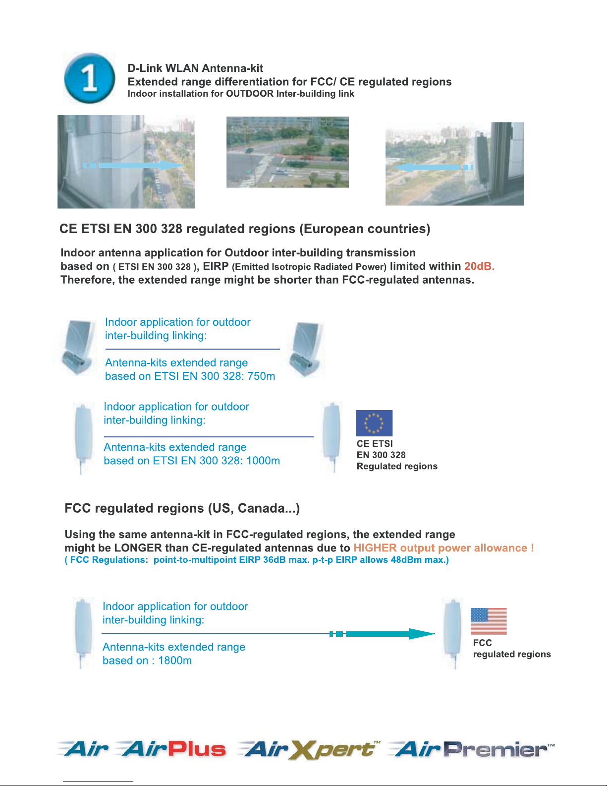
ANT24 Series
These products can be compliant with D-Link Air, Air Plus
products to make your wireless LAN have better linking quaulity.
D-Link Fast Antenna Kits
Page 2
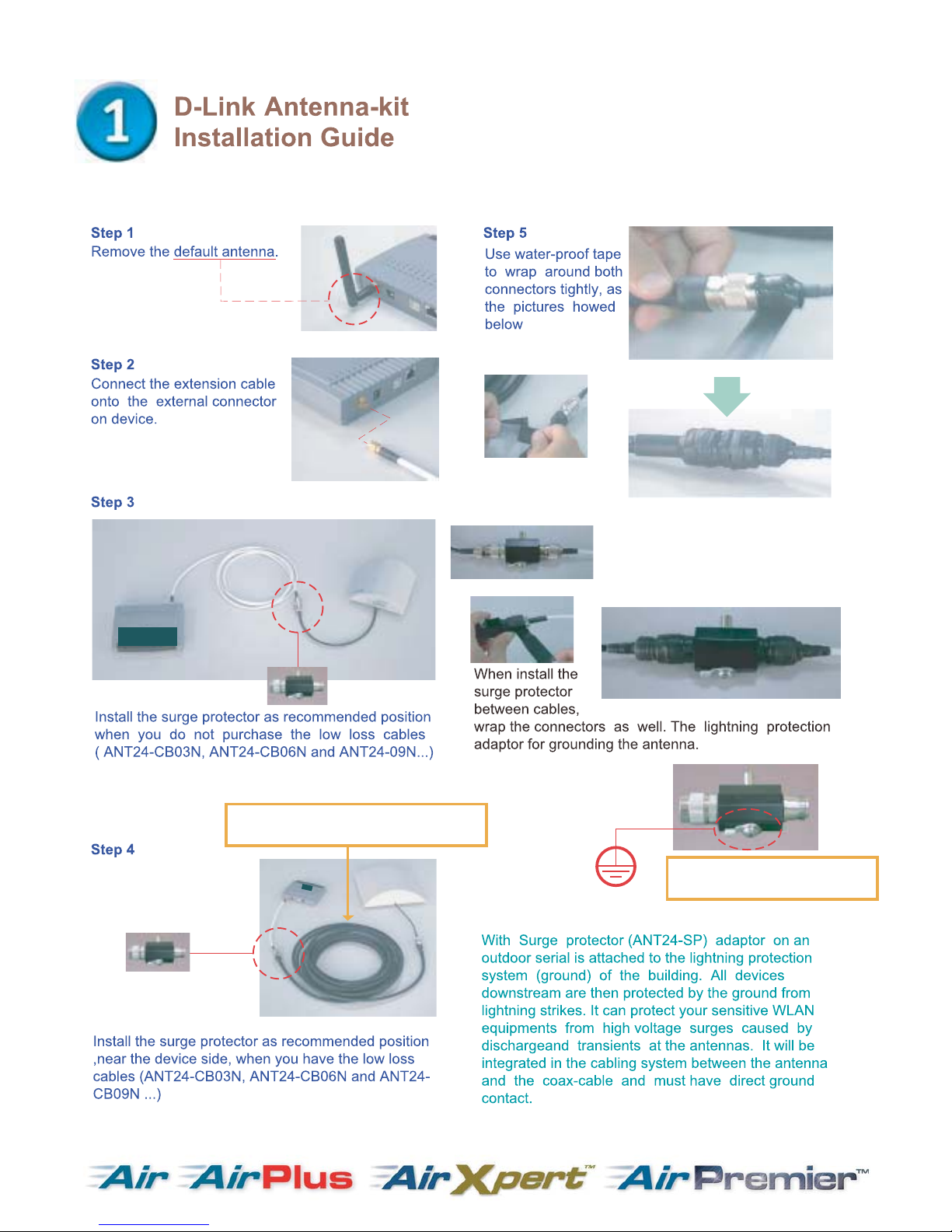
CAUTION!!
Please always put the surge protector
indoors and near the device
side, if you cannot keep it indoors,
use the tapes to wrap all the connectors
as pictures showed below.
Option: Ultra low-loss cable HDF-400
Length options: 3M/6M/9M
Option: Surge protector
Connectors: N-plug to N-jack
Page 3
Page 4
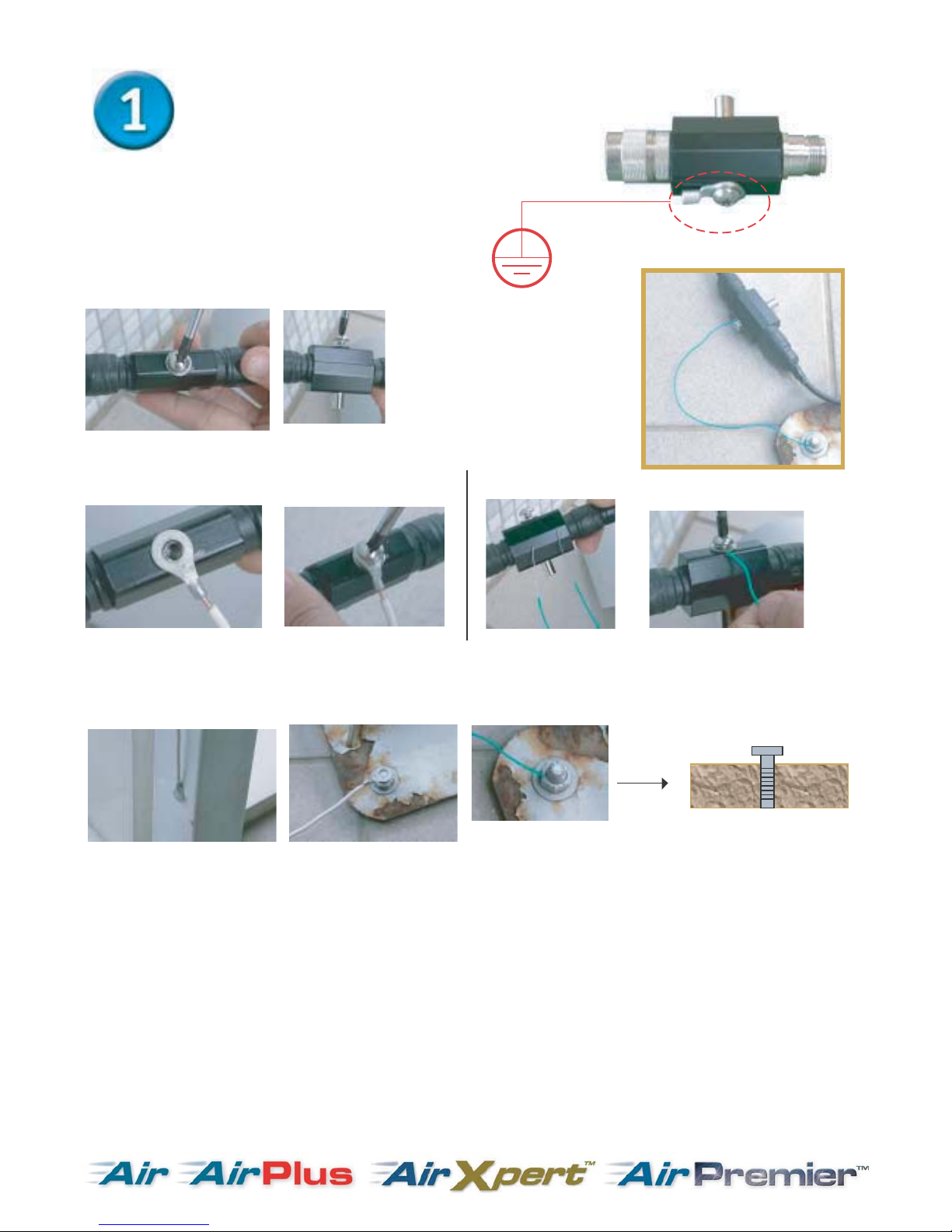
ANT24-SP Surge protector
Installation guide
for outdoor antenna-kit
Step 1
loosen the screw from the surge protector.
Step 2
get a normal conductive copper wire with 2 sides stripped long enough to be conductive,
these wires can lead high voltage surges into the grounding.
Remark:
(1) for the ground screw you use, we suggest the longer (deeper into ground) the better performance it has.
(2) please use a copper wire with diameter at least from 2.0mm, the thicker the diameter, the higher
voltage it can sustain.
Option (1)
Option (2)
Ground
Step 3
find a conductive material nearby the antenna installation sites, connect another end of the wire
into position, there are several options:
(1) Use a long screw to stick into the ground tightly, connect another wire onto.
(2) fix or solder another end of wire onto a steel material/ bar under steel construction,
such as wall for buildings, railings or other conductive materials which set up from
the ground.
Page 5

Optional ultra low attenuation cable for
ANT24-Outdoor high gain series
ANT24-0800
ANT24-120
1
Default extension cables
ANT24-1800
ANT24-1400
ANT24-0801
We have the following
length options to create
flexible antenna deployment:
P/N: ANT24-CB03N: 3meter @ 0.78dB attenuation
P/N: ANT24-CB06N: 6meter @ 1.56dB attenuation
P/N: ANT24-CB09N: 9meter @ 2.34dB attenuation
NOTE:
The longer cable you use, the more
attenuation it causes, therefoe,
the extended range might be shorten than a normal link with
default extension cables.
Page 6

Using ANT24-JC jumper cable to switch to smaller connector
which can be compliant with DWL-660 WLAN card.
ANT24-JC jumper cable
Page 7
Silver to Antenna
Golden to Device
To have correct connection of the attached
extension cable (Based on connector color management)
Page 8
Page 9

Page 10

Page 11

Silver to Antenna
Golden to Device
To have correct connection of the attached
extension cable (Based on connector color management)
Page 12

Page 13

Page 14

Pole mounting
method 1.
Pole mounting
method 2.
Page 15

Page 16

Page 17

50AT
Omni
D-Link's Omni Directional Antenna offers the most cost
effective solution for extending the wireless LAN coverage
area. The antenna is fully compatible with all products and
can be used with any 2.40 to 2.4835 GHz products.
5.0dBi Typical
2.0:1 Max.
Toroidal
60 degree
nominal
197 mm(length)
29.5gw
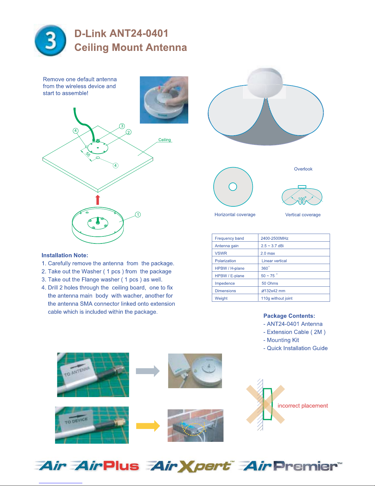
Installation:
1. Remove the original antenna from your
wireless device.
2. Screw the DWL-50AT RP- SMA connector
into your wireless device.
3. Adjust the antenna to the suitable direction
for extending the wireless coverage area.
Page 18

Page 19

R60AT
D-Link's Single Patch Flat Antenna offers the most cost
effective solution for extending the wireless LAN coverage
area. The antenna is fully compatible with all products and
can be used with any 2.40 to 2.4835 GHz products.
Installation:
1. Remove the original antenna from your
wireless device.
2. Screw the DWL-R60AT RP- SMA connector
into your wireless device.
3. Adjust the antenna to the suitable direction for
extending the wireless coverage area.
6.0dBi Typical
2.0:1 Max.
90
75
nominal
80x85x12.8 mm
75gw
- DWL-R60AT Antenna
Page 20

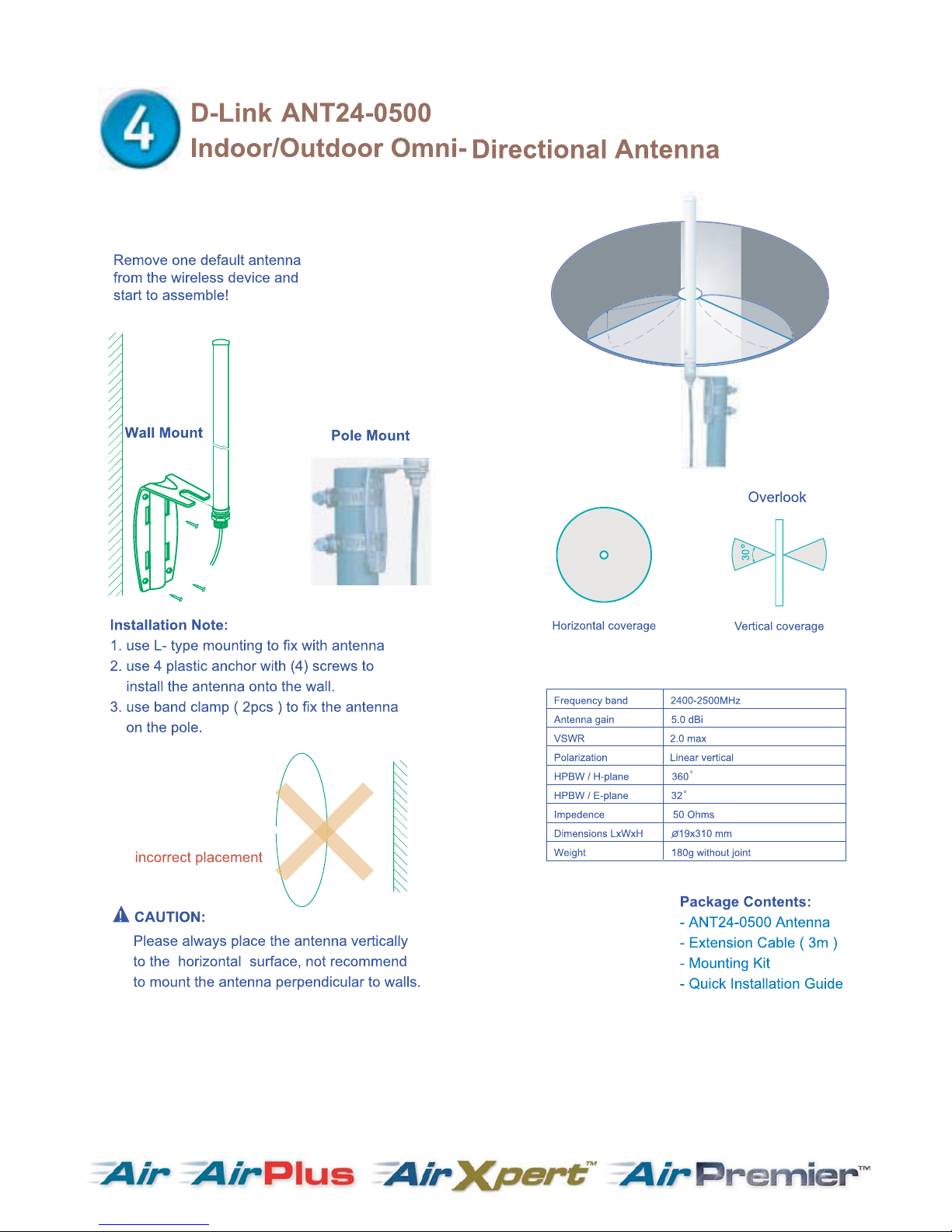
Outdoor Omni Antenna
Page 21
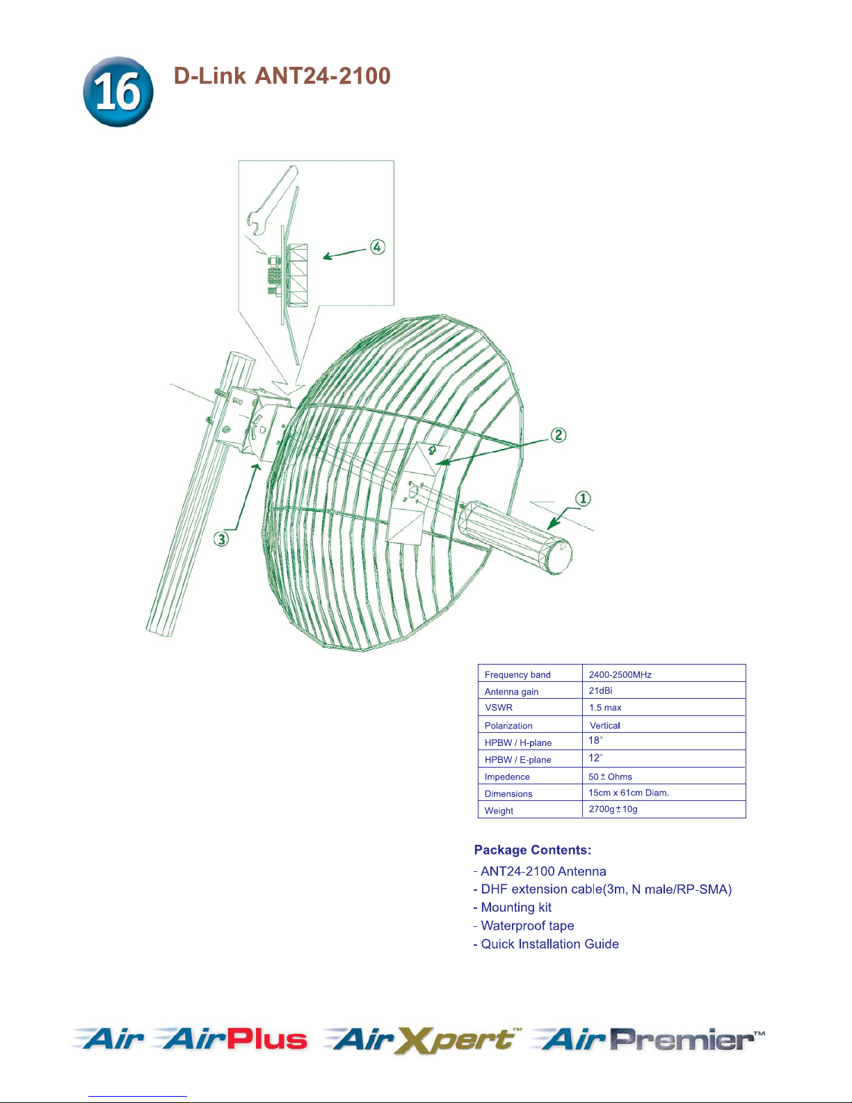
Outdoor Grid Antenna
Page 22

Indoor/ Outdoor Antenna Table:
Model Name
DWL-R60AT DWL-M60AT ANT24-0400 ANT24-0401 ANT24-0500
Signal directivity
Directional Antenna Directional Antenna Omni-directional Omni-directional Omni-directional
Application range
Indoor only Indoor only Indoor only Indoor ceiling only Indoor/ Outdoor
Gain (Without cable loss)
6dBi 6dBi 4dBi 3.5dBi 5dBi
Approximate Range at 1 Mbps *
60M 60M 40M 40M 40M
Approximate Range at 11 Mbps *
25M 25M 15M 15M 15M
Half power beam width **
H60 V90 H80 V80 H360 V40 H360 V120 H360 V30
Pigtail cable length
NA 150cm 150cm NA 30cm
Antenna fixed connector
RP-SMA plug RP-SMA plug RP-SMA plug SMA jack N-jack
Surge protector for outdoors
--- --- --- --- Optional
Default extension cable length
NA NA NA 2M 3M
Default mounting configuration
NA Wall/ desktop Wall/ desktop Ceiling Pole
Antenna-kit weight (Kg)
300g 330g 320g 310g 540g
Optional accessories
ANT24-JC
For DWL-660 links
ANT24-JC
For DWL-660 links
ANT24-JC
For DWL-660 links
ANT24-JC
For DWL-660 links
ANT24-JC
ANT24-SP
ANT24-CB series
*1.Extended range reference based on RF-Output Power 14dbm with default cable loss
*2.The transmission distance range might depend on the two same spec antennas with default cable loss
**HPBW: Half Power Beam Width. H : horizontal plane pattern, V : vertical plane pattern
The actual Indoor range will be effected by users’ physical environment. The above figures are reference.
Page 23

Indoor/ Outdoor Antenna Table:
Model Name
ANT24-0800 ANT24-0801 ANT24-1200 ANT24-1201 ANT24-1400
Signal directivity
Omni-directional Directional
Directional Directional Directional
Application range
Outdoor Outdoor
Indoor only
Outdoor Outdoor
Gain (Without cable loss)
8dBi 8.5dBi
12dBi 12dBi 14dBi
Approximate Range at 1 Mbps *
1Km under FCC
800M under ETSI
1.2Km under FCC
800M under ETSI
2Km under FCC
1Km under ETSI
2.5Km under FCC
1Km under ETSI
3Km under FCC
1.5Km under ETSI
Approximate Range at 11 Mbps *
300M under FCC
200M under ETSI
350M under FCC
200M under ETSI
600M under FCC
300M under ETSI
750M under FCC
300M under ETSI
900M under FCC
300M under ETSI
Half power Beam width **
H360 V15 H70 V70
H80 V23 H50 V50 H30 V30
Pigtail cable length
NA 30cm
NA 30cm 30cm
Antenna fixed connector
N-jack N-jack
SMA jack
N-jack N-jack
Surge protector for outdoors
Included Included
---
Included Included
Default Extension Cable Length
50cm 3M
3M 50cm 50cm
Default mounting configuration
Pole Wall/ pole
Window/ wall Wall/ pole Wall/ pole
Antenna-kit weight (kg)
1.4Kg 1.04Kg
530g 380g 2.35Kg
Optional accessories
Ultra low loss cable
For ANT24-CB series
Ultra low loss cable
For ANT24-CB series
Ultra low loss cable
For ANT24-CB series
Ultra low loss cable
For ANT24-CB series
Ultra low loss cable
For ANT24-CB series
*1.Extended range reference based on RF-Output Power 14dbm with default cable loss
*2.The transmission distance range might depend on the two same spec antennas with default cable loss
**HPBW: Half Power Beam Width. H : horizontal plane pattern, V : vertical plane pattern
The actual Indoor range will be effected by users’ physical environment. The above figures are reference.
Page 24

Indoor/ Outdoor Antenna Table:
Model Name
ANT24-1800 ANT24-1801 ANT24-1500 ANT24-2100
Signal directivity
Directional Directional
Omni-directional Directional
Application range
Outdoor Outdoor
Outdoor Outdoor
Gain (Without cable loss)
18dBi 18dBi
15dBi 21dBi
Approximate Range at 1 Mbps *
5Km under FCC
1.2Km under ETSI
5Km under FCC
1.2Km under ETSI
1Km 1Km
Approximate Range at 11 Mbps *
1.5Km under FCC
300M under ETSI
1.5Km under FCC
300M under ETSI
300M 300M
Half power Beam width **
H15 V15 H15 V15
H360 V5 H18 V12
Pigtail cable length
NA NA
NA NA
Antenna fixed connector
N-jack N-jack
N-jack N-jack
Surge protector for outdoors
Included Included
Included Included
Default Extension Cable Length
50cm 50cm
3M 3M
Default mounting configuration
Wall/ pole Pole
Pole Pole
Antenna-kit weight (Kg)
3.2Kg 4.22Kg
2.5Kg 4Kg
Optional accessories
Ultra low loss cable
For ANT24-CB series
Ultra low loss cable
For ANT24-CB series
Ultra low loss cable
For ANT24-CB series
Ultra low loss cable
For ANT24-CB series
*1.Extended range reference based on RF-Output Power 14dbm with default cable loss
*2.The transmission distance range might depend on the two same spec antennas with default cable loss
**HPBW: Half Power Beam Width. H : horizontal plane pattern, V : vertical plane pattern
The actual Indoor range will be effected by users’ physical environment. The above figures are reference.
 Loading...