

Page 1

TM
D-Link Air
DWL-700AP
2.4GHz
Wireless Access Point
Manual
Building Networks for People
Page 2

Content s
Package Contents ................................................................................3
Introduction............................................................................................4
Wireless Basics....................................................................................6
Getting Started......................................................................................8
Using the Configuration Utility................................................................9
Networking Basics ..............................................................................20
Troubleshooting...................................................................................33
T echnical S pecifications ......................................................................38
Contacting T echnical Support ..............................................................40
2
Page 3
Package Contents
Contents of Package:
D-Link Air DWL-700AP
!
2.4 GHz Wireless Access Point
Power Supply - 5V DC, 2.0A
!
Manual on CD
!
Quick Installation Guide
!
Ethernet Cable
!
If any of the above items are missing, please contact your reseller.
Note: Using a power supply with a different voltage rating than the one included
with the DWL-700AP will cause damage and void the warranty for this product.
System Requirements:
Computer with Windows, Macintosh, or Linux-based
!
operating system with an installed Ethernet adapter
Internet Explorer or Netscape Navigator version 6.0 or above,
!
with JavaScript enabled
3
Page 4

Introduction
The D-Link Air DWL-700AP Wireless Access Point is an 802.11b high-performance
wireless Access Point. It is an ideal way to extend the reach and number of computers
connected to your wireless network.
The DWL-700AP is compatible with existing 802.1 1b devices such as the D-Link Air and
AirPlus family of products including the DWL-650 and DWL-650+ Wireless Cardbus
Adapters, the DI-614+ Wireless Router, and the DWL-120 Wireless USB Adapter .
After completing the steps outlined in the Quick Installation Guide (included in your
package) you will have the ability to share information and resources, such as files
and printers, and enjoy the freedom that wireless networking delivers.
The DWL-700AP is compatible with most popular operating systems, including
Macintosh, Linux and Windows, and can be integrated into a large network. This
Manual is designed to help you connect the Access Point and the D-Link Wireless
Adapters into a network in Infrastructure mode. Please take a look at the Getting
Started section in this manual to see an example of an Infrastructure network using
the DWL-700AP .
The IEEE 802.11b Ethernet standard allows you to connect computers and 802.11b
compatible devices at speeds up to 11Mbps, dependent upon the distance between
wireless adapters, the configuration of your working environment, or the capabilities or
limitations of your computer systems.
4
Page 5
Features and Benefits
Fully 802.1 1b Compatible – Fully compatible with the IEEE 802.11b standard
!
and interoperable with all existing 802.1 1b compliant devices
! Stronger Network Security with up to 128-bit WEP Encryption – Supports 64/
128-bit WEP encryption for higher level of security for your data and wireless
communication than encryption found in existing 802.11b product s
! Built-in DHCP Server – If enabled, it will automatically assign IP addresses to
wireless clients on the local network.
! Web-based interface for Managing and Configuring – Easy-to-use interface
independent of the operating system
LEDS
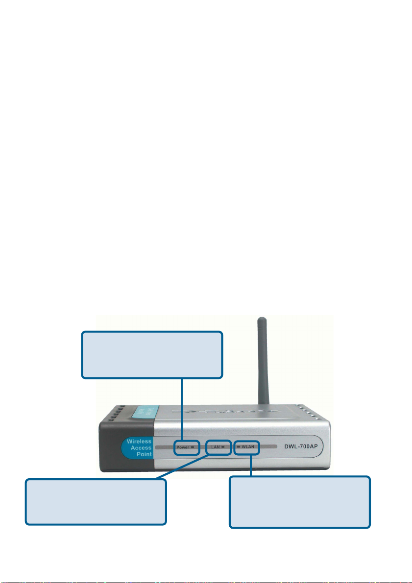
LED stands for Light-Emitting Diode. The DWL-700AP Wireless Access Point has 3
LEDs as shown below:
Power: solid green light
indicates connection to a
power source
LAN: blinking green light
indicates activity; solid green
light indicates connection
WLAN: blinking green light
indicates wireless activity;
solid green light indicates
connection
5
Page 6

Wireless Basics
D-Link wireless products are based on industry standards to provide easy-to-use and
compatible high-speed wireless connectivity within your home, business or public access
wireless networks. D-Link wireless products will allow you access to the data you want,
when and where you want it. Y ou will be able to enjoy the freedom that wireless networking
brings.
A Wireless Local Area Network (WLAN) is a cellular computer network that transmits
and receives data with radio signals instead of wires. WLANs are used increasingly in
both home and office environments, and public areas such as airports, coffee shops and
universities. Innovative ways to utilize WLAN technology are helping people to work and
communicate more efficiently . Increased mobility and the absence of cabling and other
fixed infrastructure have proven to be beneficial for many users.
Wireless users can use the same applications they use on a wired network. Wireless
adapter cards used on laptop and desktop systems support the same protocols as
Ethernet adapter cards.
People use WLAN technology for many different purposes:
Mobility - Productivity increases when people have access to data in any location
within the operating range of the WLAN. Management decisions based on real-time
information can significantly improve worker efficiency .
Low Implementation Costs – WLANs are easy to set up, manage, change and
relocate. Networks that frequently change can benefit from WLANs ease of
implementation. WLANs can operate in locations where installation of wiring may be
impractical.
Installation and Network Expansion - Installing a WLAN system can be fast
and easy and can eliminate the need to pull cable through walls and ceilings. Wireless
technology allows the network to go where wires cannot go - even outside the home or
office.
Scalability – WLANs can be configured in a variety of ways to meet the needs of
specific applications and installations. Configurations are easily changed and range
from peer-to-peer networks suitable for a small number of users to larger infrastructure
networks to accommodate hundreds or thousands of users, depending on the number
of wireless devices deployed.
Inexpensive Solution - Wireless network devices are as competitively priced as
conventional Ethernet network devices.
6
Page 7

Wireless Basics (continued)
Installation Considerations
Keep in mind, however, that the number, thickness and location of walls, ceilings, or
other objects that the wireless signals must pass through, may limit the range. Typical
ranges vary depending on the types of materials and background RF (radio frequency)
noise in your home or business. The key to maximizing wireless range is to follow these
basic guidelines:
11
1
11
Keep the number of walls and ceilings between the DWL-700AP and
other network devices to a minimum - each wall or ceiling can reduce
your D-Link Air Wireless product’s range from 3-90 feet (1-30 meters.)
Position your devices so that the number of walls or ceilings is minimized.
Be aware of the direct line between network devices. A wall that is 1.5 feet thick
22
2
22
(.5 meters), at a 45-degree angle appears to be almost 3 feet (1 meter) thick. At
a 2-degree angle it looks over 42 feet (14 meters) thick! Position devices so
that the signal will travel straight through a wall or ceiling (instead of at an angle)
for better reception.
33
3
33
4
Building Materials can impede the wireless signal - a solid metal door or aluminum
studs may have a negative effect on range. Try to position wireless devices and
computers with wireless adapters so that the signal passes through drywall or
open doorways and not other materials.
Keep your product away (at least 3-6 feet or 1-2 meters) from electrical
44
44
devices or appliances that generate RF noise.
7
Page 8
Getting Started
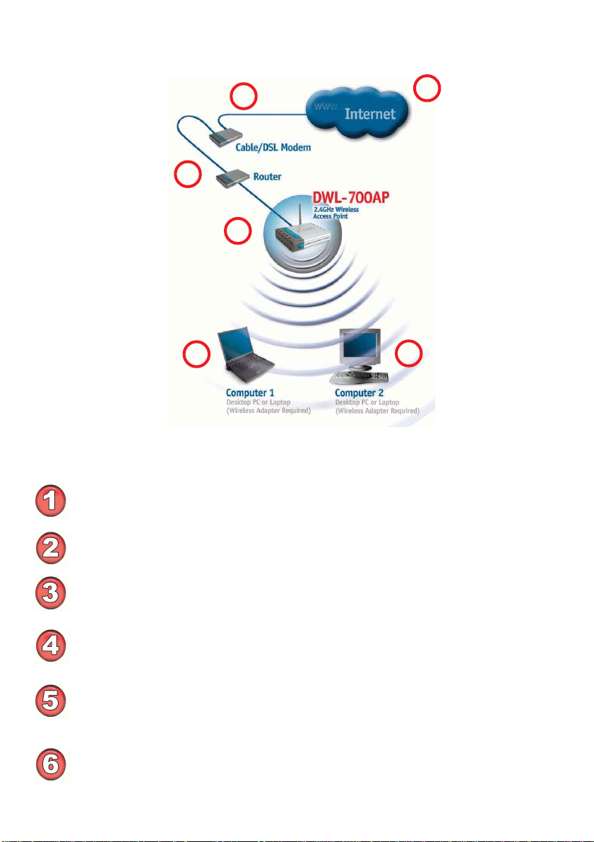
Setting up a Wireless
Infrastructure Network
3
2
4
1
5
Please remember that D-Link Air wireless devices are pre-configured to connect
together, right out of the box, with their default settings.
For a typical wireless setup at home (as shown above), please do the following:
You will need broadband Internet access (a Cable or DSL-subscriber line into
your home or office)
Consult with your Cable or DSL provider for proper installation of the modem
Connect the Cable or DSL modem to your broadband router (see the Quick
Installation Guide included with your router.)
Connect the router to the D-Link Air DWL-700AP.
(See the Quick Installation Guide included with the DWL-520.)
If you are connecting a desktop computer in your network, you can install the
D-Link Air DWL-520 wireless PCI adapter into an available PCI slot on your
desktop computer.
(See the Quick Installation Guide included with the DWL-520.)
Install the drivers for the wireless Cardbus adapter into a laptop computer .
(e.g, the DWL-650; See the Quick Installation Guide included with the DWL-
650.)
6
8
Page 9
Using the Configuration Utility
If you wish to change the default settings or optimize the performance of the
DWL-700AP , D-Link has included a configuration utility for this purpose.
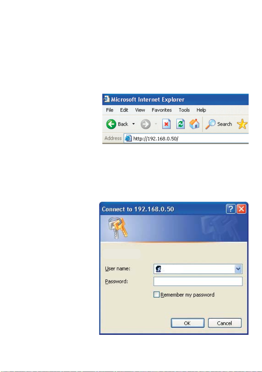
Whenever you want to configure your network or the DWL-700AP , you can access the
Configuration Utility by opening the web-browser and typing in the IP Address of the
DWL-700AP. The DWL-700AP’s default IP Address is shown below:
Open the web browser
!
Type in the IP Address
!
of the Access Point
(The IP Address shown in the example above is the default setting. Use this IP address
when connecting to a network consisting of other D-Link devices set to their default
settings. If you have changed the IP Address of the DWL-700AP to conform to a network other than one with D-Link devices, then input that IP Address in the web browser,
instead of the default IP Address shown.)
Type admin in the
!
User Name field
Leave the Password
!
blank
Click OK
!
admin
9
Page 10
Using the Configuration Utility (continued)
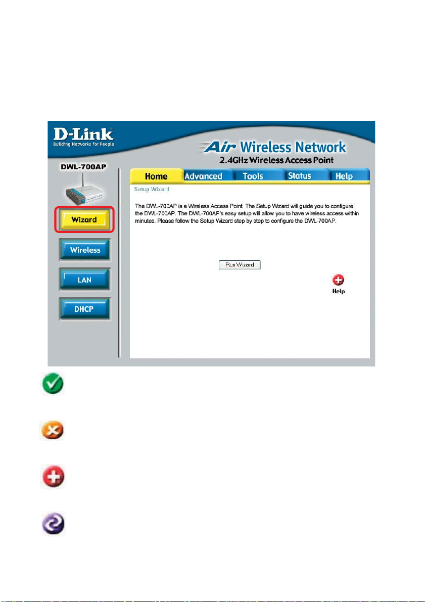
After logging in, the screen below will appear . Click on the tabs in the screen to
access different segments of the Configuration Utility . If you choose to use the webbased configuration menu, please configure the DWL-700AP from a computer with an
ethernet connection to the DWL-700AP .
Home > Wizard
Apply
Cancel
Help
Restart
Clicking Apply will save changes made to the page
Clicking Cancel will clear changes made to the page
Clicking Help will bring up helpful information regarding the page
Clicking Restart will restart the router . (Necessary for some changes.)
10
Page 11
Using the Configuration Utility (continued)
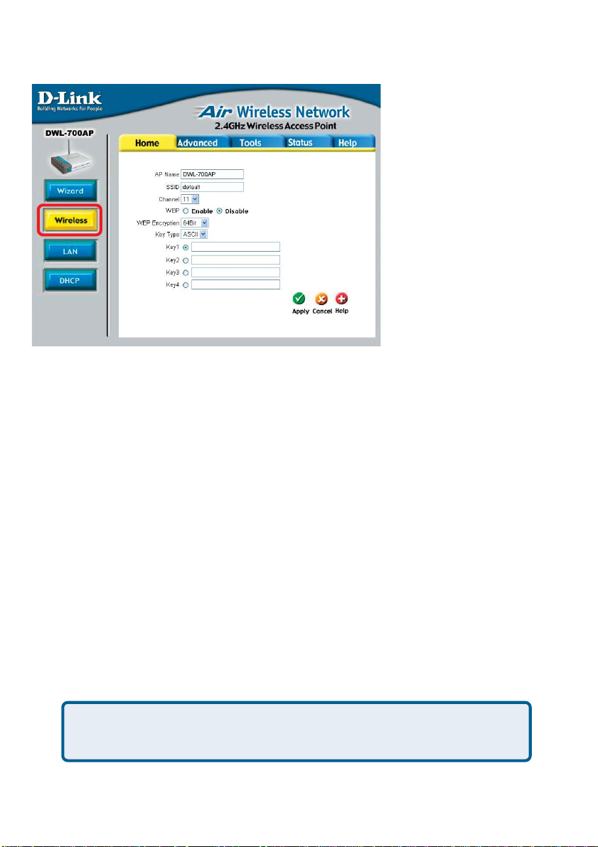
Home > Wireless
AP Name: You may choose to rename your Access Point, especially if you have
more than one Access Point on your network.
SSID: (Service Set Identifier) default is the default setting. The SSID is a unique
name that identifies a network. All devices on a network must share the same SSID
name in order to communicate on the network. If you choose to change the SSID from
the default setting, input your new SSID name in this field. The SSID can be up to 32
characters in length.
Channel: Channel 6 is the default channel. Input a new number if you want to change
the default setting. All devices on the network must be set to the same channel to
communicate on the network.
WEP Encryption: Select Enable Encryption to use WEP (Wired Equivalent Privacy)
on the network. All devices on the network, and the Access Point, must share the same
WEP selection – either Enable or Disable, and they must share the same WEP key.
The WEP key is generated from ASCII or Hexadecimal entries that are either 64, 128,
or 256 bit in length.
When enabling encryption, select the Key T yp e (ASCII or Hexadecimal) and then input
the appropriate digits or letters. You can create up to 4 keys. Select the key you wish
to use.
Hexadecimal digits consist of the numbers 0-9 and the letters A-F
ASCII (American Standard Code for Information Interchange) is a code for
representing English letters as numbers from 0-127
11
Page 12
Using the Configuration Utility (continued)
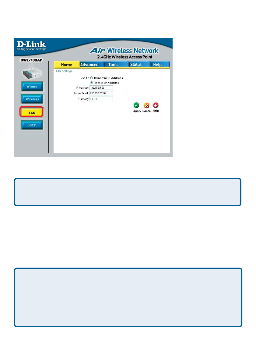
Home > LAN
Dynamic IP Address: Select this option if you would like to have an IP Address
automatically assigned to the DWL-700AP by a DHCP server in your network.
DHCP stands for Dynamic Host Configuration Protocol. It is a protocol for assigning dynamic IP addresses “automatically .” With a DHCP Server there is no need to
manually assign an IP Address.
Static IP Address: Select this option if you are manually assigning an IP Address.
IP Address: 192.168.0.50 is the default IP Address of the Access Point.
Subnet Mask: 255.255.255.0 is the default Subnet Mask. All devices on the
network must have the same subnet mask to communicate on the network
Gateway: Enter the IP Address of the gateway in your network
IP Address
If you need to assign St atic IP Addresses to the devices in your network, please
remember that the IP Address for each computer or device must be in the same IP
Address range as all the devices in the network. Each device must also have the
same Subnet Mask. For example: Assign the first computer an IP Address of
192.168.0.2 and a Subnet Mask of 255.255.255.0, the second device an IP Address of 192.168.0.3 and a Subnet Mask of 255.255.255.0, and so on. Devices that
are assigned the same IP Address may not be visible on the network.
12
Page 13
Using the Configuration Utility (continued)
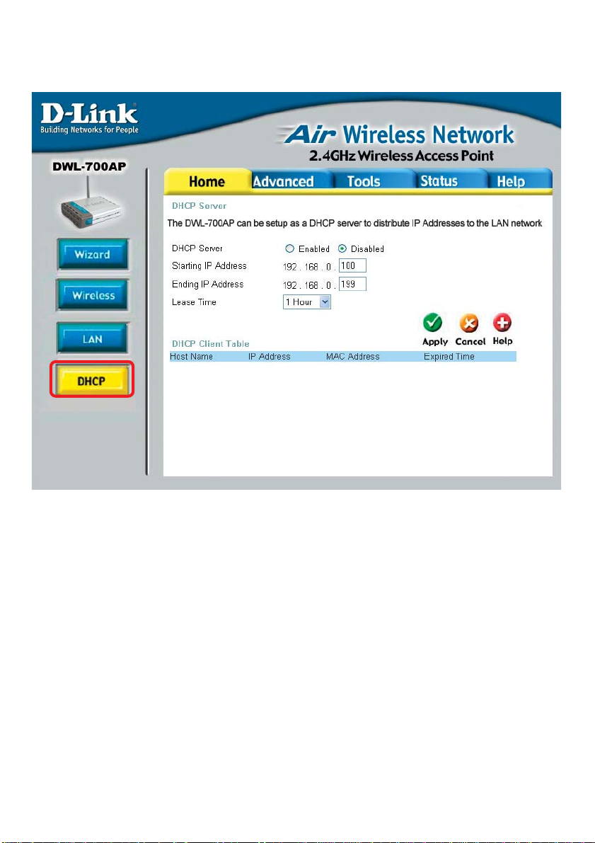
Home > DHCP
DHCP Server: Select Enabled or Disabled. Disabled is the default setting. If
you want to use the Access Point as a DHCP server to automatically assign Dynamic
IP Addresses on the network, you will select Enabled.
Starting IP Address: If you have enabled the DHCP server function, enter the
starting point of the IP Address range for your network
Ending IP Address: Enter the ending IP Address of your IP Address range, if you
have enabled the DHCP function of the Access Point
Lease Time: Choose the length of time at which the DHCP function of the
DWL-700AP automatically regenerates the IP Addresses to the devices in your
network
DHCP Client T able: Lists the devices on your network that are receiving dynamic
IP Addresses from the Access Point
13
Page 14

Using the Configuration Utility (continued)
The default Performance
settings are shown here.
Advanced > Performance
Beacon Interval: Beacons
are packets sent by an Access
Point to synchronize a wireless
network. Specify a Beacon
interval value. Default (100) is
recommended.
RTS Threshold: This value
should remain at its default
setting of 2,432. If you encounter inconsistent data flow, only
minor modifications to the value
range between 256 and 2,432
are recommended.
Fragmentation: This value should remain at its default setting of 2,346. If you expe-
rience a high packet error rate, you may slightly increase your Fragmentation Threshold
within the value range of 256 to 2,346. Setting the Fragmentation Threshold too low may
result in poor performance.
DTIM Interval (Beacon Rate): (Delivery Traffic Indication Message) Enter a value
between 1 and 255 (default is 3) for the Delivery Traf fic Indication Message (DTIM.) A
DTIM is a countdown informing clients of the next window for listening to broadcast and
multicast messages.
Basic Rates: Default is 1-2Mbps. We recommend that you keep the setting at default.
If you lose connection at the TX rate, you will regain connection at the basic rate. A lower
Basic Rate will make reconnection easier.
TX Rates: Select the transmission rate for the network. The default rate is 1-2-5.5-
1 1-22Mbp s.
Preamble: Long Preamble is the default setting. (High traffic networks should use the
shorter preamble type.) The preamble defines the length of the CRC block (Cyclic Redundancy Check is a common technique for detecting data transmission errors) used in
communication between the Access Point and the roaming wireless Network adapters.
Authentication:
Open System - communicates the key across the network
Shared Key - devices must have identical WEP settings to communicate
Auto - automatically adjusts to the Authentication mode of the wireless client
SSID Broadcast: (Service Set Identifier) Enable or Disable (default) the broadcast
of the SSID name across the network. SSID is a name that identifies a wireless
network. All devices on a network must use the same SSID to est ablish communication.
14
Page 15

Using the Configuration Utility (continued)
Advanced > Filters
Use MAC Filters to allow or deny computers by their MAC addresses from access-
ing the DWL-700AP. You can either manually add a MAC address or select the MAC
address from the list of clients that are currently connected to the Broadband Router
(Connected PCs). The default setting is Disabled MAC Filters.
MAC Filter List: This list will display the MAC addresses that are in the selected
filter
15
Page 16

Using the Configuration Utility (continued)
T ools > Admin
New Password: Enter the
new password
Confirm Password:
Re-enter the password to
confirm it
T ools > System
Save Settings: The current
system settings can be saved
as a file onto the local hard
drive.
Load Settings: The saved
file or any other saved setting
file can be loaded back on the
Access Point. To reload a system settings file, click on
Browse to browse the local
hard drive and locate the system file to be used. Click Load
when you have selected the file
to be loaded back onto the Ac-
cess Point.
Restore: You may also reset the Access Point back to factory settings by clicking on
Restore. Make sure to save the unit’s settings before clicking on Restore.
16
Page 17

Using the Configuration Utility (continued)
T ools > Firmware
Y ou can upgrade
the firmware of the
Access Point at
this page. Make
sure the firmware
you want to use is
on the local hard
drive of the
computer. Click on
Browse to browse
the local hard drive
and locate the
firmware to be used
for the update.
Please check the DLink support site for
firmware updates at
http://
support.dlink.com.
Once you have found the firmware to be used, click Apply.
D-Link Access Point
This screen displays
the current Wireless
and Ethernet settings
of the DWL-700AP .
Status > Device Info
17
Page 18

Using the Configuration Utility (continued)
Status > Log
View Log
The Access Point keep s a running log of events and activities occurring on the AP. If the
device is rebooted, the logs are automatically cleared. Y ou may save the log files under
Log Setting.
First Page - The first page of the log.
Last Page - The last page of the log.
Previous - Moves back one log page.
Next - Moves forward one log page.
Clear - Clears the logs completely .
Log Settings - Brings up the page to configure the logs.
Log Settings
Not only does the Access Point display the logs of activities and event s, it can be setup
to send these logs to another location. The logs can be sent via email to an email
account.
SMTP Server - The address of the SMTP server that will be used to send the logs.
Send to - The email address the logs will be sent to. Click on Email Log Now to send
the email.
18
Page 19

Using the Configuration Utility (continued)
Status> Stats
Traffic Statistics
The Access Point keep s statistics
of traffic that passes through it. You
are able to view the amount of
packets that passes through the
Router on both the Ethernet portion
of the network and the Wireless
portion of the network. The traffic
counter will reset if the device is
rebooted.
Status > Wireless
Connected
Wireless PCs LIst
This list displays the MAC
Addresses of connected PC’s and
the length of time that they have
been connected.
DWL-700AP
Menu
Select from this menu for extra
help.
Help
19
Page 20

Networking Basics
Using the Network Setup Wizard in Windows XP
In this section you will learn how to establish a network at home or work, using
Microsoft Windows XP.
Note: Please refer to websites such as
and http://www.microsoft.com/windows2000 for information about networking
computers using Windows 2000, ME or 98SE.
Go to Start>Control Panel>Network Connections
Select Set up a home or small office network
http://www.homenethelp.com
When this screen appears, click Next.
20
Page 21

Networking Basics
Please follow all the instructions in this window:
Click Next
In the following window, select the best description of your computer . If your
computer connects to the internet through a gateway/router, select the second option
as shown.
Click Next
21
Page 22

Networking Basics
Enter a Computer description and a Computer name (optional.)
Click Next
Enter a Workgroup name. All computers on your network should have the same
Workgroup name.
Click Next
22
Page 23

Networking Basics
Please wait while the Network Setup Wizard applies the changes.
When the changes are complete, click Next.
Please wait while the Network Setup Wizard configures the computer.
This may take a few minutes.
23
Page 24

Networking Basics
In the window below, select the option that fit s your needs. In this example, Create
a Network Setup Disk has been selected. You will run this disk on each of the
computers on your network. Click Next.
Insert a disk into the Floppy Disk Drive, in this case drive A.
24
Page 25

Networking Basics
Please read the information under Here’s how in the screen below. After you complete the Network Setup Wizard you will use the Network Setup Disk to run the
Network Setup Wizard once on each of the computers on your network. To continue
click Next.
25
Page 26

Networking Basics
Please read the information on this screen, then click Finish to complete the
Network Setup Wizard.
The new settings will take effect when you restart the computer . Click Yes to restart
the computer.
Y ou have completed configuring this computer. Next, you will need to run the Network
Setup Disk on all the other computers on your network. After running the Network
Setup Disk on all your computers, your new wireless network will be ready to use.
26
Page 27

Networking Basics
Naming your Computer
To name your computer, please follow these directions:In Windows XP:
Click Start (in the lower left corner of the screen)
!
Right-click on My Computer
!
Select Properties and click
!
Select the Computer
!
Name Tab in the System
Properties window.
!
You may enter a Computer Description if you
wish; this field is optional.
To rename the computer
!
and join a domain, Click
Change.
27
Page 28

Networking Basics
Naming your Computer
!
In this window, enter the
Computer name
Select Workgroup and enter
!
the name of the Workgroup
All computers on your network
!
must have the same
Workgroup name.
Click OK
!
Checking the IP Address in Windows XP
The wireless adapter-equipped computers in your network must be in the same IP
Address range (see Getting Started in this manual for a definition of IP Address Range.)
To check on the IP Address of the adapter, please do the following:
Right-click on the
!
Local Area
Connection icon
in the task bar
Click on Status
!
28
Page 29

Networking Basics
Checking the IP Address in
This window will appear.
Click the
!
Support tab
Click Close
!
Windows XP
Assigning a Static IP Address in Windows XP/2000
Note: Residential Gateways/Broadband Routers will automatically assign IP Addresses to the computers on the network, using DHCP (Dynamic Host Configuration Protocol) technology. If you are using a DHCP-capable Gateway/Router you
will not need to assign Static IP Addresses.
If you are not using a DHCP capable Gateway/Router , or you need to assign a S tatic IP
Address, please follow these instructions:
Go to Start
!
Double-click on
!
Control Panel
29
Page 30

Networking Basics
Assigning a Static IP Address in
Double-click on
!
Network
Connections
Windows XP/2000
Right-click on Local Area
!
Connections
Double-click on
!
Properties
30
Page 31

Networking Basics
Assigning a Static IP Address
in Windows XP/2000
Click on Internet Protocol
!
(TCP/IP)
Click Properties
!
In the window below, select Use the following IP address. Input your IP
!
!
address and subnet mask. (The IP Addresses on your network must be
within the same range. For example, if one computer has an IP Address of
192.168.0.2, the other computers should have IP Addresses that are
sequential, like 192.168.0.3 and 192.168.0.4. The subnet mask must be
the same for all the computers on the network.)
IP Address:
e.g., 192.168.0.2
Subnet Mask:
255.255.255.0
Default Gateway:
Enter the LAN IP address of
the wireless router. (D-Link
wireless routers have a LAN IP
address of 192.168.0.1)
Select Use the following
!
DNS server address. Enter
the LAN IP address of the
Wireless Router. (D-Link
wireless routers have a LAN
IP address of 192.168.0.1)
!
Click OK
You have completed the assignment of a S tatic IP Address. (Y ou do not need to assign
a Static IP Address if you have a DHCP-capable Gateway/Router.)
31
Page 32

Networking Basics
Checking the Wireless Connection by
Pinging in Windows XP and
2000
Go to Start > Run >
!
type cmd. A window
similar to this one
will appear. Type
ping
xxx.xxx.xxx.xxx,
where xxx is the IP
Address of the
Wireless Router or
Access Point. A
good wireless
connection will show
four replies from the
Wireless Router or
Acess Point, as
shown.
Checking the Wireless Connection by Pinging in Windows Me
and 98
Go to Start > Run
!
> type command.
A window similar to
this will appear.
Type ping
xxx.xxx.xxx.xxx
where xxx is the IP
Address of the
Wireless Router or
Access Point. A
good wireless
connection will
show four replies
from the wireless
router or access
point, as shown.
32
Page 33

Troubleshooting
This chapter provides solutions to problems that can occur during the installation and
operation of the DWL-700AP . W e cover various aspects of the network including network
adapters. (The examples below are illustrated in Windows XP. If you have another
operating system, these solutions will still apply although the appearance on your computer screen may differ.)
Note: It is recommended that you use an Ethernet connection to configure the
DWL-700AP Access Point.
1. The computer used to configure the DWL-700AP cannot access the
Configuration menu.
Check that the Ethernet LED on the DWL-700AP is ON. If the LED is
not ON, check that the cable for the Ethernet connection is securely
inserted.
Check that the Ethernet Adapter is working properly. Please see item
3 (Check that the drivers for the network adapters are installed
properly) in this Troubleshooting section to check that the drivers
are loaded properly .
Check that the IP Address is in the same range and subnet as the
DWL-700AP. Please see Checking the IP Address in Windows XP
in the Networking Basics section of this manual.
Note: The IP Address of the DWL-700AP is 192.168.0.50. All the computers on the
network must have a unique IP Address in the same range, e.g., 192.168.0.x. Any
computers that have identical IP Addresses will not be visible on the network.
They must all have the same subnet mask, e.g., 255.255.255.0
Do a Ping test to make sure that the DWL-700AP is responding. Go to
Start>Run>Type Command>Type ping 192.168.0.50. A successful
ping will show four replies.
33
Page 34

Troubleshooting (continued)
2. The wireless client cannot access the Internet in the Infrastructure
mode.
Make sure the wireless client is associated and joined with the correct Access
Point. To check this connection: Right-click on the Local Area Connection
icon in the taskbar> select View Available Wireless Networks. The Connect
to Wireless Network screen will appear. Please make sure you have selected
the correct available network, as shown in the illustrations below.
Note: Screen shots were taken
using Windows XP. Y our
screens may look similar.
default
default
Check that the IP Address assigned to the wireless adapter is within the same
IP Address range as the access point and gateway. Since the DWL-700AP
has an IP Address of 192.168.0.50, wireless adapters must have an IP Address
in the same range, e.g., 192.168.0.x. Each device must have a unique IP Address;
no two devices may have the same IP Address. The subnet mask must be the
same for all the computers on the network. To check the IP Address assigned
to the wireless adapter, double-click on the Local Area Connection icon in
the taskbar > select the Support tab and the IP Address will be displayed.
(Please refer to Checking the IP Address in the Networking Basics section of
this manual.)
If it is necessary to assign a Static IP Address to the wireless adapter, please
refer to the appropriate section in Networking Basics. If you are entering a
DNS Server address you must also enter the Default Gateway Address.
(Remember that if you have a DHCP-capable router , you will not need to assign
a Static IP Address. See Networking Basics: Assigning a Static IP
Address.)
34
Page 35

Troubleshooting (continued)
3. Check that the drivers for the network adapters are installed properly.
You may be using different network adapters than those illustrated here, but this
procedure will remain the same, regardless of the type of network adapters you are
using.
Go to Start
Right-click on My Computer
Click Properties
Select the Hardware Tab
Click Device Manager
35
Page 36

Troubleshooting (continued)
Double-click on Network
Adapters
Right-click on DLink Air DWL-650 Wireless
Cardbus Adapter
(or whatever network adapter
you are using)
Select Properties to check that
the drivers are installed properly
Look under Device Status to
check that the device is
working properly .
D-Link Air DWL-650 Wireless Cardbus Adapter
D-Link Air DWL-650 Wireless Cardbus Adapter
D-Link Air DWL-650 Wireless Cardbus Adapter
Cardbus
Click OK
36
Page 37

T roubleshooting (continued)
4. Resetting the DWL-700AP to Factory Default Settings
After you have tried other methods for troubleshooting your network, you may
choose to Reset the DWL-700AP to the factory default settings. Remember that DLink Air products network together , out of the box, at the factory default settings.
T o hard-reset the D-Link Air DWL-700AP to Factory Default Settings, please do the
following:
Locate the Reset button on the back of the DWL-700AP
Use a paper clip to press the Reset button
Hold for about 5 seconds and then release
After the DWL-700AP reboots (this may take a few minutes) it will be reset
to the factory default settings.
37
Page 38

Technical Specifications
Standards
IEEE 802.1 1
!
IEEE 802.1 1b
!
IEEE 802.3
!
IEEE 802.3u
!
Port:
10/100 Mbps Fast Ethernet
!
Data Rates:
1, 2, 5.5, 1 1Mbps (with Automatic Fallback)
!
Encryption:
Supports 64-bit,128,256-bit RC4
!
Media Access Controll:
CSMA/CA with ACK
!
Frequency Range:
2.4 – 2.462GHz
!
Operating Range:
Indoors - up to 328 feet (100 meters)*
!
Modulation Technology:
DSSS - Direct Sequence Spread Spectrum
!
11-chip Barker sequence
!
38
Page 39

T echnical Specifications (continued)
Modulation Techniques
Barker (1Mbps/0db)
!
Barker (2Mbps/3db)
!
CCK (5.5Mbps/5.5db)
!
CCK (11Mbps/8.5db)
!
Transmitter Output Power:
16dBm
!
External Antenna Type:
1.8dBi gain with reverse SMA
!
connector
Over-Driving Levels:
Tolerates up to +17dBm at
!
the Antenna
Device Management
Web-Based - Internet
!
Explorer v5 or later;
Netscape Navigator v4 or
later; or other Java-enabled
browsers.
Physical Dimensions:
L = 5.5 inches
!
(140mm)
W = 4.5 inches
!
(114mm)
H = 1 inches
!
(25.4mm)
LEDs:
Power (Green)
!
Link (Green)
!
TX/RX (Green)
!
Power Input:
External Power
!
Supply: DC 5V, 2.5A
Weight:
.11 lbs. (51g)
!
Warranty:
1 Y ear
!
Operating Temperature:
5ºC to 40ºC
!
Humidity:
5% - 95%, non-condensing
!
Safety & Emissions
FCC
!
!
CSA
39
Page 40

Federal Communication Commission Interference Statement
This equipment has been tested and found to comply with the limits for a Class B
digital device, pursuant to Part 15 of the FCC Rules. These limits are designed
to provide reasonable protection against harmful interference in a residential
installation. This equipment generates, uses and can radiate radio frequency
energy and, if not installed and used in accordance with the instructions, may
cause harmful interference to radio communications. However, there is no
guarantee that interference will not occur in a particular installation. If this
equipment does cause harmful interference to radio or television reception, which
can be determined by turning the equipment off and on, the user is encouraged to
try to correct the interference by one of the following measures:
- Reorient or relocate the receiving antenna.
- Increase the separation between the equipment and receiver.
- Connect the equipment into an outlet on a circuit different from that to which
the receiver is connected.
- Consult the dealer or an experienced radio/TV technician for help.
This device complies with Part 15 of the FCC Rules. Operation is subject to the
following two conditions: (1) This device may not cause harmful interference, and
(2) this device must accept any interference received, including interference that
may cause undesired operation.
FCC Caution: Any changes or modifications not expressly approved by the party
responsible for compliance could void the user's authority to operate this
equipment.
IMPORTANT NOTE:
FCC Radiation Exposure Statement:
This equipment complies with FCC radiation exposure limits set forth for an
uncontrolled environment. This equipment should be installed and operated with
minimum distance 20cm between the radiator & your body.
This transmitter must not be co-loc ated or operating in conjunction with any other
antenna or transmitter.
INFORMATION TO USER:
The users manual or instruction manual for an intentional or unintentional radiator
shall caution the user that changes or modifications not expressly approved by
the party responsible for compliance could void the user’s authority to operate the
equipment.
Page 41

T echnical Support
Y ou can find software updates and user documentation on the D-Link website.
D-Link provides free technical support for customers within the United St ates and
within Canada for the duration of the warranty period on this product.
U.S. and Canadian customers can contact D-Link technical support through our
website, or by phone.
Tech Support for customers within the United States:
D-Link Technical Support over the Telephone:
(877) 453-5465
24 hours a day, seven days a week.
D-Link Technical Support over the Internet:
http://support.dlink.com
email:support@dlink.com
Tech Support for customers within Canada:
D-Link Technical Support over the Telephone:
(800) 361-5265
Monday to Friday 8:30am to 9:00pm EST
D-Link Technical Support over the Internet:
http://support.dlink.ca
email:support@dlink.ca
061203
 Loading...