

Page 1

PHANTOM 2 VISION
User Manual V1.06
December 12, 2013 Revision
Congratulations on purchasing your new DJI product. Please thoroughly read the entire contents of this manual to
fully use and understand the product.
It is advised that you regularly check the PHANTOM 2 VISION’s product page at www.dji.com which is
updated on a regular basis. This will provide services such as product information, technical updates and manual
corrections. Due to any unforeseen changes or product upgrades, the information contained within this manual is
subject to change without notice.
If you have any questions or concerns regarding your product, please contact your dealer or DJI Customer Service.
©2013 DJI Innovations. All Rights Reserved.
Page 2

Index
INDEX ........................................................................................................................................................................................................ 2
IN THE BOX ............................................................................................................................................................................................ 4
REQUIRED ITEMS ................................................................................................................................................................................. 4
SYMBOL LEGEND ................................................................................................................................................................................. 5
WATCH THE QUICK START VIDEOS .............................................................................................................................................. 5
DOWNLOADING THE DJI VISION APP ......................................................................................................................................... 5
1 ATTACHING THE PROPELLERS ....................................................................................................................................................6
1.1 INTRODUCTION .............................................................................................................................................................................................. 6
1.2 ASSEMBLY ...................................................................................................................................................................................................... 6
1.3 REMOVING THE PROPELLERS..................................................................................................................................................................... 6
1.4 NOTES ............................................................................................................................................................................................................ 6
2 INSTALLING THE RANGE EXTENDER AND MOBILE DEVICE HOLDER .......................................................................... 7
2.1 INSTALLING THE RANGE EXTENDER ......................................................................................................................................................... 7
2.2 INSTALLING THE MOBILE DEVICE HOLDER ............................................................................................................................................ 7
3 PREPARING THE REMOTE CONTROLLER ............................................................................................................................... 8
3.1 THE REMOTE CONTROLLER ....................................................................................................................................................................... 8
3.2 POWER ON THE REMOTE CONTROLLER ................................................................................................................................................ 8
3.3 REMOTE CONTROLLER POWER INDICATOR STATUS INFORMATION ............................................................................................... 9
3.4 ANTENNA ORIENTATION ........................................................................................................................................................................... 9
3.5 REMOTE CONTROLLER OPERATION ..................................................................................................................................................... 10
3.6 LINK BETWEEN THE REMOTE CONTROLLER AND RECEIVER .............................................................................................................. 11
Link Procedures ......................................................................................................................................................................................... 12
Link Indicator .............................................................................................................................................................................................. 12
3.7 COMPLIANCE VERSION CONFIGURATION ............................................................................................................................................ 12
4 PREPARING THE RANGE EXTENDER ....................................................................................................................................... 14
4.1 THE RANGE EXTENDER .............................................................................................................................................................................. 14
4.2 FUNCTION DESCRIPTION .......................................................................................................................................................................... 14
4.3 POWERING ON THE RANGE EXTENDER ................................................................................................................................................. 15
4.4 HOW TO BIND THE CAMERA & RANGE EXTENDER ............................................................................................................................ 15
5 PREPARING THE CAMERA ........................................................................................................................................................... 18
5.1 THE BUILT-IN CAMERA ................................................................................................................................................................................ 18
5.2 MAIN FUNCTIONS ...................................................................................................................................................................................... 18
5.3 UPGRADING THE FIRMWARE OF CAMERA ........................................................................................................................................... 20
6 DOWNLOADING AND INSTALLING THE DJI VISION APP ................................................................................................ 21
6.1 DOWNLOAD AND INSTALL ......................................................................................................................................................................... 21
6.2 REGISTER & LOGIN .................................................................................................................................................................................... 21
7 PREPARING THE FLIGHT BATTERY ......................................................................................................................................... 23
7.1 INTELLIGENT BATTERY AND CHARGER INSTRUCTIONS ...................................................................................................................... 23
7.2 CHARGING PROCEDURES ........................................................................................................................................................................ 23
7.3 INSTALL THE BATTERY .............................................................................................................................................................................. 24
©2013 DJI Innovations. All Rights Reserved.
Page 3

7.4 BATTERY USAGE ........................................................................................................................................................................................ 24
Description of the Battery Level Indicator...................................................................................................................................... 25
7.5 CORRECT BATTERY USAGE NOTES ....................................................................................................................................................... 25
8 PHANTOM 2 AIRCRAFT ............................................................................................................................................................... 26
8.1 THE AIRCRAFT ............................................................................................................................................................................................ 26
8.2 BUILT-IN FLIGHT CONTROL SYSTEM INSTRUCTIONS ......................................................................................................................... 26
8.3 LED FLIGHT INDICATORS DESCRIPTION .............................................................................................................................................. 26
9 CONNECTING TO THE CAMERA ............................................................................................................................................. 28
9.1 CAMERA CONNECTION PROCEDURES .................................................................................................................................................. 28
10 CALIBRATING THE COMPASS ................................................................................................................................................. 30
10.1 CALIBRATION WARNINGS ..................................................................................................................................................................... 30
10.2 CALIBRATION PROCEDURES ................................................................................................................................................................ 30
10.3 WHEN RECALIBRATION IS REQUIRED................................................................................................................................................. 30
11 FLIGHT ................................................................................................................................................................................................ 31
11.1 FLYING ENVIRONMENT REQUIREMENTS ................................................................................................................................................ 31
11.2 STARTING THE MOTORS ........................................................................................................................................................................... 31
11.3 TAKEOFF/LANDING PROCEDURES ......................................................................................................................................................... 31
11.4 FAILSAFE FUNCTION ................................................................................................................................................................................ 32
Home Point ................................................................................................................................................................................................. 33
Go Home Procedures ............................................................................................................................................................................. 33
Regaining Control During Failsafe Procedure .............................................................................................................................. 33
Failsafe on the DJI VISION App ......................................................................................................................................................... 33
11.5 LOW BATTERY CAPACITY WARNING FUNCTION ...............................................................................................................................34
DJI VISION App Low Battery Capacity Warning.........................................................................................................................34
12 DJI VISION APP USAGE .............................................................................................................................................................. 36
12.1 DJI VISION APP MAIN MENU .............................................................................................................................................................. 36
12.2 CAMERA PAGE ......................................................................................................................................................................................... 36
Basic Use ................................................................................................................................................................................................... 36
Camera Settings ...................................................................................................................................................................................... 40
12.3 ALBUM PAGE ............................................................................................................................................................................................43
Camera SD CARD Album ......................................................................................................................................................................43
Mobile Device Album ............................................................................................................................................................................. 44
12.4 NEWS PAGE ..............................................................................................................................................................................................45
12.5 SETTINGS PAGE ....................................................................................................................................................................................... 46
13 ASSISTANT SOFTWARE INSTALLATION AND CONFIGURATION ............................................................................... 50
13.1 INSTALLING THE DRIVER AND ASSISTANT SOFTWARE ...................................................................................................................... 50
13.2 USING THE PHANTOM 2 VISION ASSISTANT SOFTWARE ON A PC ........................................................................................ 50
13.3 FIRMWARE UPGRADE OF THE PHANTOM 2 VISION ..................................................................................................................... 51
13.4 PHANTOM RC ASSISTANT SOFTWARE DESCRIPTION .................................................................................................................. 52
14 TROUBLESHOOTING(FAQ) ................................................................................................................................................ 53
15 APPENDIX ........................................................................................................................................................................................ 56
LED FLIGHT INDICATOR STATUS .................................................................................................................................................................. 56
SPECIFICATIONS ............................................................................................................................................................................................... 57
©2013 DJI Innovations. All Rights Reserved. 3 |
Page 4
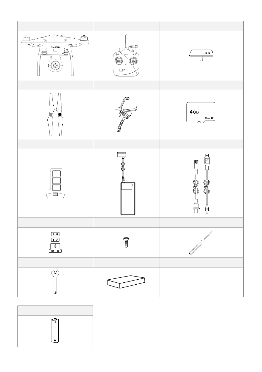
In the Box
PHANTOM 2 VISION X1
5.8GHz Remote Controller X1
Range Extender X1
Propeller Pair X4
Mobile Device Holder X1
Micro-SD Card X1
Intelligent Battery X1
Charger X1
Cables X1
Plug Set X1
Screw X12
Screwdriver X 1
Assistant Wrench X1
Accessories Box X1
AA Battery x4
Required Items
©2013 DJI Innovations. All Rights Reserved. 4 |
Page 5
Symbol Legend
Forbidden(Important)
Caution
Tip Reference
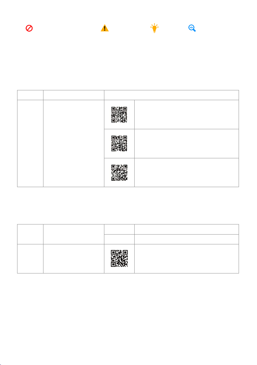
Approach 1
Direct link.
www.dji.com/phantom-2-vision/training
Approach 2
Scan the QR code to get the
quick start video link.
Preparing for flight.
How to connect to the DJI VISION App.
The basics of flying, recording and sharing.
Approach 1
Download from the App store
or Google Play.
iOS user
Search “DJI VISION” from App Store.
Android user
Search “DJI VISION” from Google Play.
Approach 2
Scan the QR code to get the
download link.
Scan and download.
Watch the Quick Start Videos
This user manual details installation and usage procedures of the product. In addition, we provide a range of quick
start videos. It is advised that you watch them fully before attempting to use the product.
Downloading the DJI VISION App
Before attempting to use the product, please download and install the DJI VISION App. Get the DJI VISION App
according to the following methods.
©2013 DJI Innovations. All Rights Reserved. 5 |
Page 6
1 Attaching the Propellers
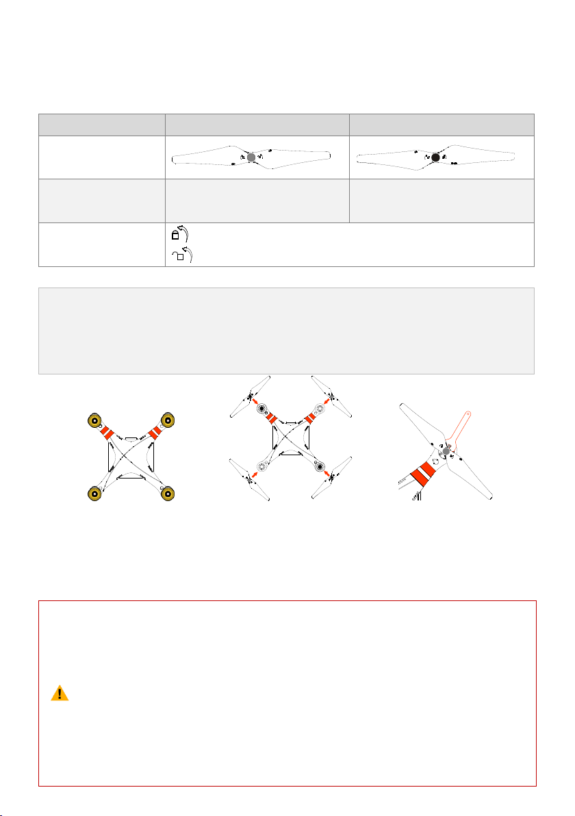
Propellers
Grey Nut (9443)
Black Nut (9443 R)
Diagram
Assembly Location
Attach to the motor thread that does
not have a black dot.
Attach to the motor thread that has a
black dot.
Fastening/Un-fastening
Instructions
Lock: Tighten the propeller in this direction.
Unlock: Remove the propeller in this direction.
1.
2.
(Fig.1) Remove the four warning cards from the motors after you read them.
(Fig.2) Prepare the two grey nut propellers and two black nut propellers. Make sure to match the black nut
propellers with the correctly marked black dot motors. Tighten the propellers according to the fastening
instructions.
(1)
(2)
(3)
(4)
(5)
(6)
(7)
Propellers are self tightening during flight. DO NOT use any thread locker on the threads.
Make sure to match the propeller nut colors with the corresponding motors.
It is advised to wear protective gloves during propeller assembly and removal.
Check that the propellers and motors are installed correctly and firmly before every flight.
Check that all propellers are in good condition before flight. DO NOT use any ageing, chipped,
or broken propellers.
To avoid injury, STAND CLEAR of and DO NOT touch the propellers or motors when they are
spinning.
ONLY use original DJI propellers for a better and safer flight experience.
Please use the original 9-inch propellers which are classified by the color of each central nut. Damaged propellers
can be replaced by purchasing new ones if necessary.
1.1 Introduction
1.2 Assembly
Fig.1 Fig.2 Fig.3
1.3 Removing the Propellers
(Fig.3) Keep the motor deadlocked in place with the assistant wrench (or one hand) and remove the propeller
according to the un-fastening instructions.
1.4 Notes
©2013 DJI Innovations. All Rights Reserved. 6 |
Page 7
2 Installing the Range Extender and Mobile Device Holder
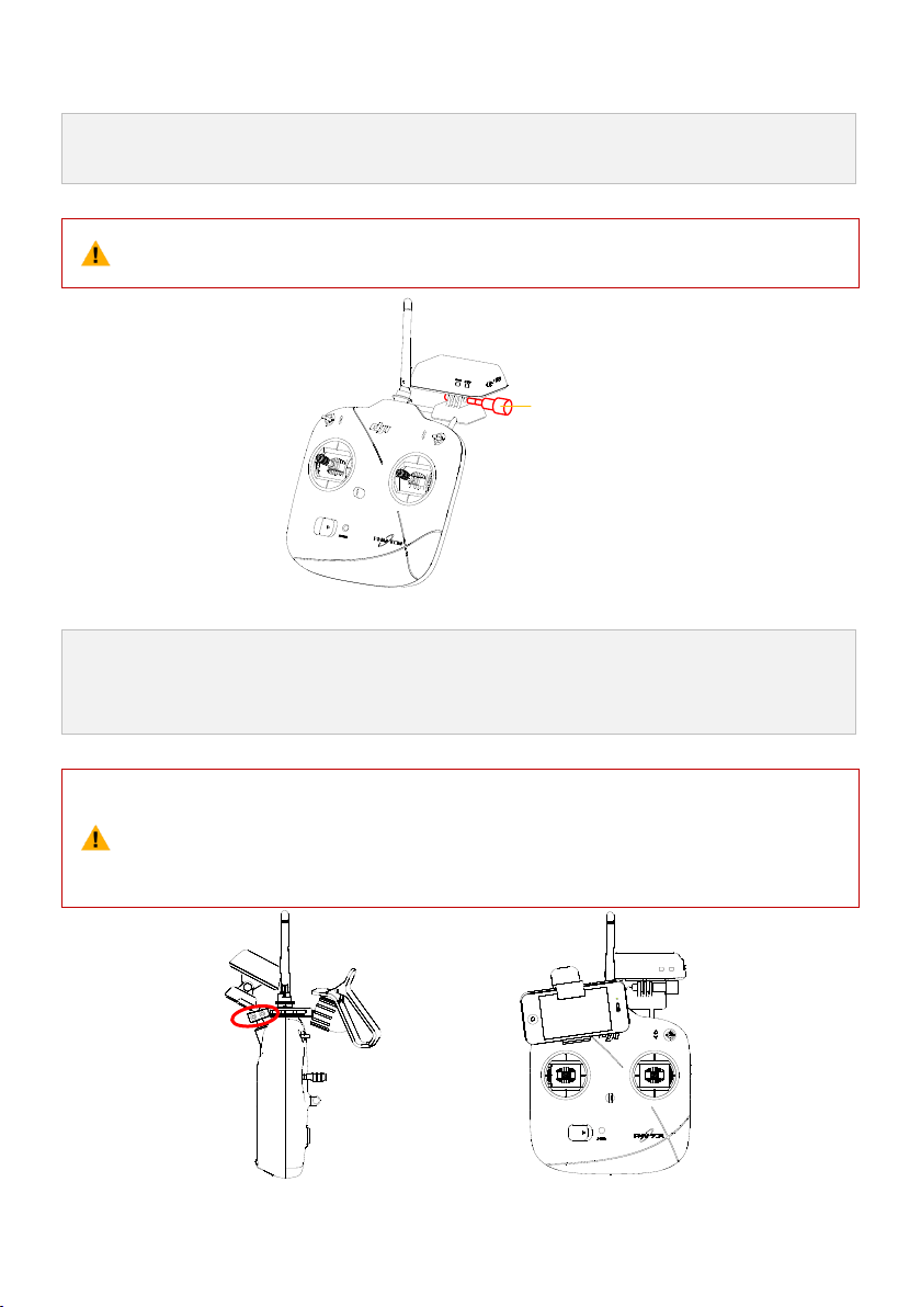
1.
2.
Adjust the range extender to align with the mounting bracket installed on the carrying handle.
Tighten the lock-screw to affix the range extender on the right side of the carrying handle.
(1)
(2)
Make sure the assembly orientation is correct with the LED side facing you.
To obtain better communication, try to keep the range extender facing the aircraft during flight.
Lock Screw
1.
2.
Tighten the Philips screws as shown to correctly attach the mobile device holder on the left side of the
carrying handle.
Affix the mobile device sideways within the holder.
(1)
(2)
Make sure the assembly orientation is correct. The mobile device should be facing you when
mounted.
It is recommended not to use oversized mobile devices (e.g. iPad), which cannot be placed into
the Mobile Device Holder.
2.1 Installing the Range Extender
2.2 Installing the Mobile Device Holder
©2013 DJI Innovations. All Rights Reserved. 7 |
Page 8
3 Preparing the Remote Controller
The PHANTOM 2 VISION remote control is a wireless communication device that uses the 5.8GHz frequency
band. It is compliant with CE and FCC (see the FCC ID) regulations and is set to Mode 2 and CE compliance
before delivery. If FCC compliance is required, it can be configured by twisting the potentiometer knob on the
back of the remote controller. The stick configuration can also be reset in the PHANTOM RC assistant software.
Please refer to < PHANTOM RC Assistant> and <Compliance Configuration> for details.
(1)
(2)
(3)
CE compliant devices have an effective communication range of 300 meters in open spaces due
to power limitations. Be sure to watch your fight distance as the PHANTOM 2 VISION will enter
Failsafe mode (auto-landing or go home and land) if it flies beyond this range.
FCC compliant devices have an effective range of 500 meters in open spaces. Be sure to watch
your fight distance as the PHANTOM 2 VISION will enter Failsafe mode (auto-landing or go
home and land) if it flies beyond this range.
Pay attention to and follow local laws and regulations.
[1]
[2]
[4]
[3]
[8]
[9]
[10]
J2
J1
J3
J4
[6]
[7]
[5]
[1]
[2]
[3]
[4]
[5]
[6]
[7]
[8]
[9]
[10]
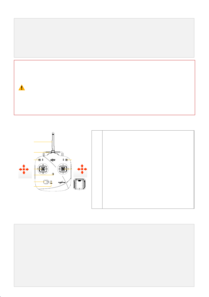
Antenna
Carrying Handle
Switch S1
Switch S2 (Reserved)
Joystick(J1: Roll [left&right], J2: Pitch [front&back])
Joystick(J3: Throttle [up&down], J4: Yaw [rotation])
Neck Strap Attachment
Power Switch
Power Indicator
Battery Compartment (On the back)
1.
2.
3.
Install the four AA Batteries (not included) into the battery compartment on the back of the remote
controller according to the negative and positive poles.
Set the S1 and S2 switches to the upper most position and all sticks are at mid-point before switching on
the power switch.
There is a power on indicator beep. If the remote controller is set to be CE compliant, then there will be
one beep while the FCC compliant version will emit 2 beeps. The power indicator blinks green quickly
indicating the remote controller and receiver is linking. Once fully linked, the power indicator will change
to a solid green.
3.1 The Remote Controller
3.2 Power on the Remote Controller
©2013 DJI Innovations. All Rights Reserved. 8 |
Page 9
(1)
(2)
(3)
(4)
If the low voltage warning alert sounds (refer to the <Remote Controller Power Indicator Status
Information>), please replace batteries as soon as possible.
Using the incorrect type of battery may prevent a risk of damage.
Remove the batteries after use and dispose of them safely.
For long term storage, be sure to remove the batteries from the remote controller.
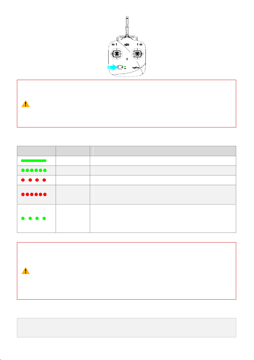
Power indicator
Sound
Remote Controller State
None
Functioning normally.
None
Establishing a link between the remote controller and the receiver.
B-B-B……
Low voltage (at 3.9V-4.5V), should replace the batteries immediately.
BBBB
Low voltage (lower than 3.9V). The remote controller will automatically
power off. Batteries should be replaced immediately.
B-B-B……
The remote controller will give a visual indication of an alarm after 15
minutes of non-operation. The alarm status will disappear once you start
operation of the remote controller.
The remote controller will blink the LED and sound an alert when the voltage drops below 3.9V and
automatically power off after 3 seconds. This process will repeat even if you power cycle the remote
controller. If this low voltage warning occurs during flight, the remote controller will automatically
power off causing the aircraft to enter Failsafe mode which cannot be interrupted (refer to <Failsafe
Function> section for details). It is strongly recommended to replace batteries if the 3.9V-4.5V low
voltage warning occurs.
Try to keep the antenna pointing skyward, perpendicular to the ground, in order to achieve the maximum
communication range during flight.
3.3 Remote Controller Power Indicator Status Information
3.4 Antenna Orientation
©2013 DJI Innovations. All Rights Reserved. 9 |
Page 10
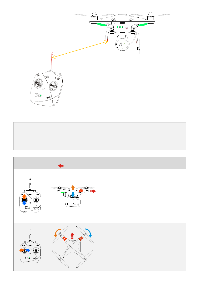
3.5 Remote Controller Operation
Definitions
The ‘stick neutral’ positions and ‘stick released’ mean the control sticks of the remote controller are placed at
the central position.
To ‘move the stick’ means that the stick of remote controller is pushed away from the central position.
Remote Controller
(Mode 2)
Aircraft
( nose direction)
Operation details
The throttle stick controls the aircraft elevation.
Push the stick up and the aircraft will rise.
Pull the stick down and the aircraft will descend.
The aircraft will automatically hover and hold its height
if the sticks are centered.
Push the throttle stick above the centered (neutral)
position to cause the aircraft to take-off. We suggest
that you push the throttle stick slowly to prevent the
aircraft from sudden and unexpected elevation.
The yaw stick controls the aircraft rudder.
Push the stick left and the aircraft will rotate counter
clock-wise.
Push the stick right and the aircraft will rotate
clock-wise. If the stick is centered, the aircraft will
always fly in the same direction.
The command stick controls the rotating angular
velocity of the aircraft. Increasing movement of the
OFF CAM ON WIFI ON
MICRO SD
The remote controller’s antenna should be
pointing skyward with no obstacles in the way.
Otherwise, the Failsafe function may initialize
prematurely during flight.
The Mobile Device and Range Extender should
not block the antenna.
©2013 DJI Innovations. All Rights Reserved. 10 |
Page 11
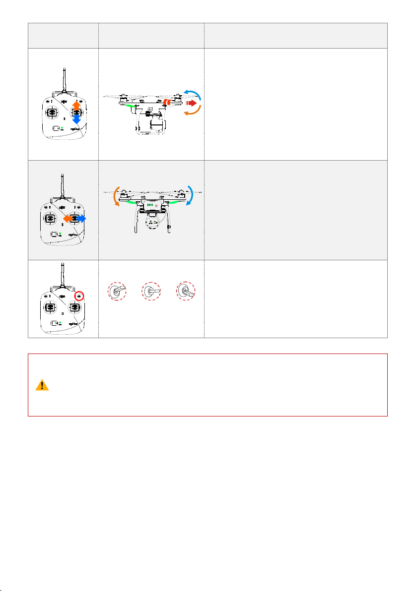
command stick results in faster aircraft rotation
velocity.
The pitch stick controls the aircraft’s front & back tilt.
Push the stick up and the aircraft will tilt and fly
forward.
Pull the stick down and the aircraft will tilt and fly
backward. The aircraft will keep level and straight if the
stick is centered.
Increasing movement of the command stick will result
in a larger tilt angle (maximum is 35˚) and faster flight
velocity.
The roll stick controls the aircraft left & right tilt.
Push the stick left and the aircraft will tilt and fly left.
Push the stick right and the aircraft will tilt and fly right.
The aircraft will keep level and straight if the stick is
centered.
Increasing movement of the command stick will result
in a larger tilt angle (maximum is 35˚) and faster flight
velocity.
Position-1 Position-2 Position-3
S1 is for compass calibration. Toggle the S1 from
position-1 to position-3 and back to position-1 about 5
times or above, which will force the aircraft to enter
into compass calibration mode.
(1)
(2)
For ‘Ready to Fly’ the aircraft will hover (hold a stable horizontal position) when all sticks are
released.
For ‘Ready to Fly (non-GPS)’ the aircraft will keep the aircraft level without horizontal
positioning when all sticks are released.
OFF CAM ON WIFI ON
MICRO SD
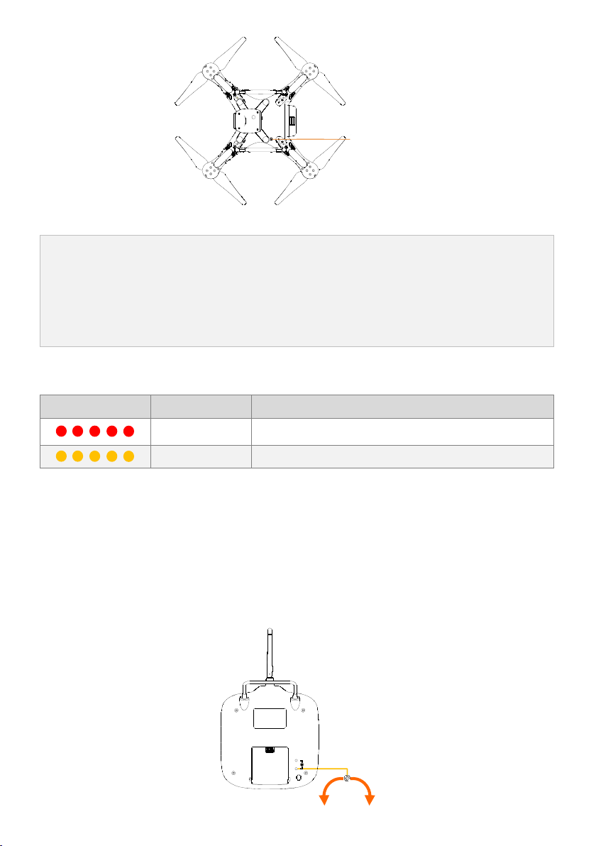
3.6 Link between the Remote Controller and Receiver
There is a 5.8G receiver in the PHANTOM 2 VISION, with the link button and indicator located on the bottom of
the aircraft as illustrated in the following diagram.
The link between the remote controller and aircraft is already established for you so you can initially skip this
procedure. If you ever replace the remote controller, re-establishing the link is required.
©2013 DJI Innovations. All Rights Reserved. 11 |
Page 12
Link Procedures
1.
2.
3.
Power off the remote controller, power on the aircraft. You will see the link indicator blinking red.
Press the link button with a thin object and hold until the link indicator blinks yellow. Release the link
button.
Power on the remote controller and the link indicator should switch off. This indicates that the link has
been successfully established.
Link Indicator
Description
Operation
No signal received.
Switch on the remote controller or perform a link procedure.
In link status.
Switch on the remote controller.
FCCCE
接收机 对频 按键
&对频指 示灯
Link Button &
Link Indicator
Link Indicator
3.7 Compliance Version Configuration
The compliance version can be reconfigured by twisting the potentiometer knob (See the following diagram) on the
back of the remote controller using a flathead screwdriver. For CE compliance, set the remote controller to CE
compliance by carefully turning the potentiometer knob to the full counter clock-wise position. For FCC compliance,
set the remote controller to FCC compliance by carefully turning the potentiometer knob to the full clock-wise
position. Users should follow their local regulations accordingly.
©2013 DJI Innovations. All Rights Reserved. 12 |
Page 13

When adjusting the potentiometer knob to its limit position, be very careful to prevent
damaging the potentiometer knob. Do not apply too much force during this adjustment. Also be
sure to use the correct sized screwdriver.
(1)
(2)
(3)
(4)
The remote controller comes set for CE compliance up delivery as the default setting.
It is recommended to use a flathead screwdriver of Φ2.4mm for adjustment.
You can use the DJI screwdriver with the flathead for adjustment.
There is another potentiometer reserved.
©2013 DJI Innovations. All Rights Reserved. 13 |
Page 14
4 Preparing the Range Extender
The PHANTOM 2 VISION range extender is a wireless communication device that operates within the 2.4 GHz
frequency band and is used for extending the effective range of communication between a mobile device
(Smartphone) and the PHANTOM 2 VISION. In an open unobstructed area, the transmission distance can reach
up to 300 meters, but is usually affected by the surrounding environment, such as trees, buildings and other
sources of the same frequency. Before every flight, it is suggested that you ensure the range extender functions
properly. Otherwise you may experience a communication issue with the mobile device and the PHANTOM 2
VISION.
Each range extender has a unique MAC address and network name (SSID), details of which are printed on the
back label as ‘Phantom_1xxxxx’. The ‘xxxxx’ represents the last five letters or numbers of the MAC address for
the range extender.
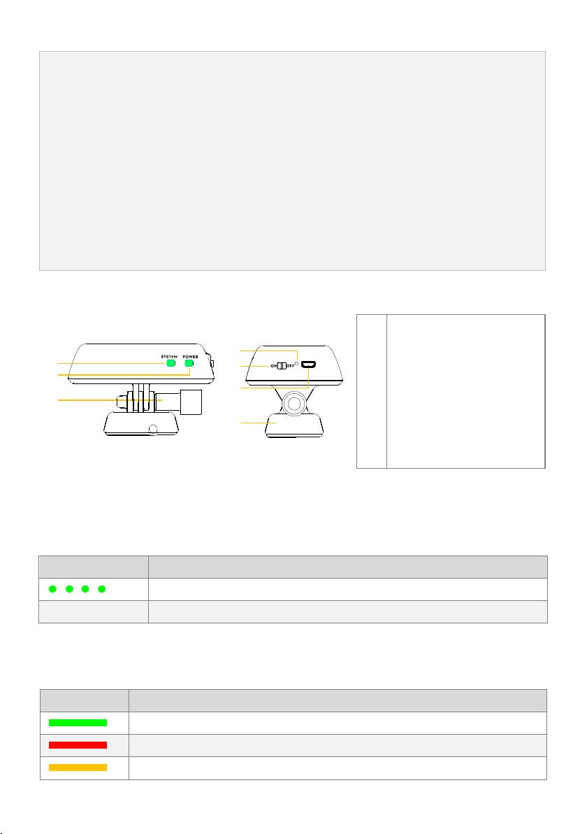
[1]
[2]
[3]
[7]
[6]
[5]
[4]
Front View Right View
[1]
[2]
[3]
[4]
[5]
[6]
[7]
Wi-Fi Signal Indicator
Power Indicator
Lock-screw
Reset Button
Power Switch
Micro-USB
Mounting Bracket
Wi-Fi Signal Indicator
Description
The range extender system is working normally.
Off
The range extender system is working abnormally.
Power Indicator
Description
The range extender is working normally or completely charged.
Low voltage alert, a re-charge is required.
The range extender is charging (allow for 3~4 hours, depending on USB power output).
4.1 The Range Extender
4.2 Function Description
[1] Wi-Fi Signal Indicator (SYSTEM)
Tells you the system status of the range extender.
[2] Power Indicator (POWER)
Tells you the power status of the range extender.
©2013 DJI Innovations. All Rights Reserved. 14 |
Page 15
(1)
(2)
(3)
(4)
(5)
Make sure to charge the range extender completely before using it for the first time.
If the power indicator is a solid red light, the ranger extender may stop working at any moment.
Recharge it as soon as possible.
It is recommended to charge the range extender completely before each use.
Turn off the range extender after every use.
Keep the range extender facing the aircraft during flight for the best communication link.
1.
2.
Toggle the power switch of range extender to ON position.
Wait for approximately 30 seconds. The Wi-Fi signal indicator should blink green indicating the range
extender is communicating properly.
It is advised that you power off the range extender after every flight to avoid discharging the battery.
[3] Lock-screw
For attaching the range extender on the right side of the remote controller’s carrying handle.
[4] Reset Button:
Press to link the range extender and the camera.
[5] Power Switch:
ON – Power on.
OFF – Power off.
[6] Micro-USB
Used to charge the range extender.
[7] Mounting Bracket
It has been pre-installed on the remote controller’s handle. It is used to attach the range extender.
4.3 Powering on the Range Extender
4.4 How to Bind the Camera & Range Extender
If the camera and range extender connection is lost, or one of them needs to be repaired or replaced, a camera and
range extender binding will need to be performed via the DJI VISION App.
©2013 DJI Innovations. All Rights Reserved. 15 |
Page 16
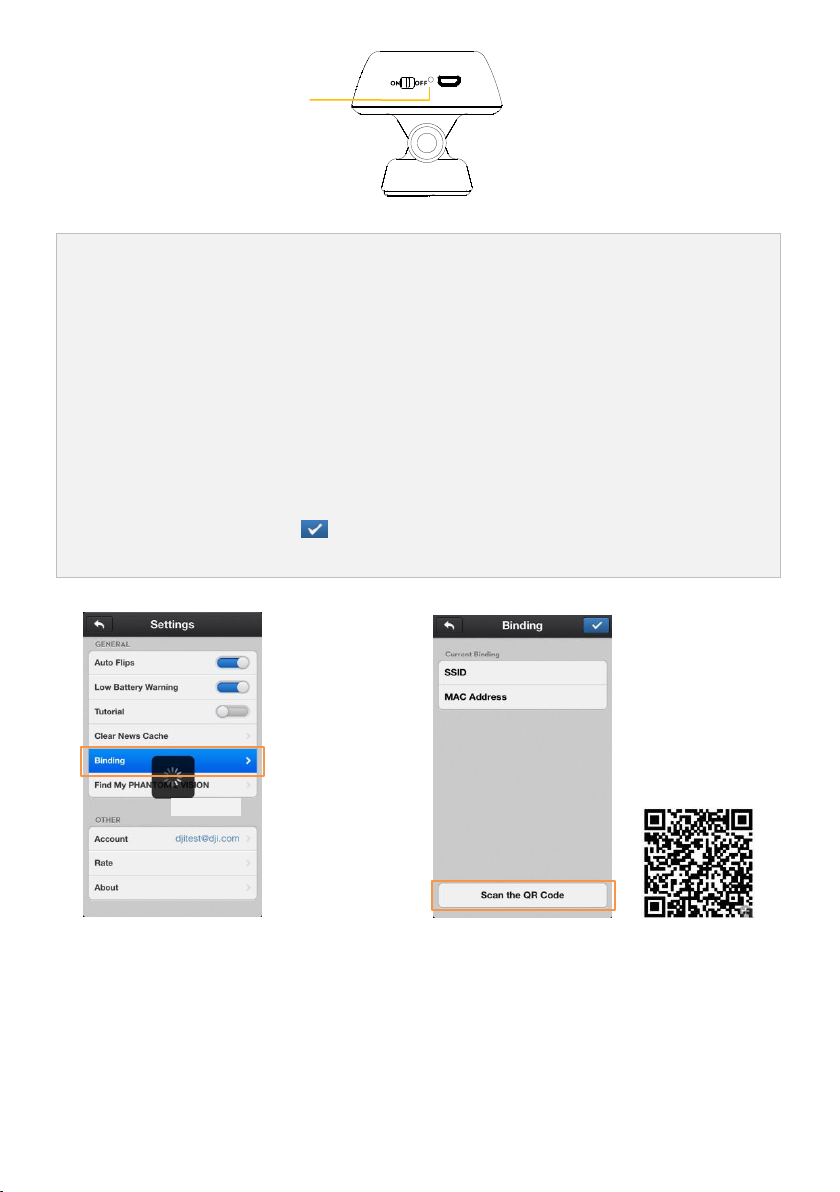
1.
2.
3.
4.
5.
Power on the camera and range extender. Note:(Place the camera power switch to the ’WIFI
ON‘ position).
Approximately 30 seconds later, press the reset button on the range extender with a thin object until the
Wi-Fi signal indicator turns off. The range extender will then restart automatically.
Approximately 30 seconds later, the Wi-Fi signal indicator should start to blink green, which indicates the
range extender is now ready to be bound.
Find and select the Phantom_1xxxxx via the Wi-Fi list on the mobile device to connect the range extender.
(Fig.1) Run the DJI VISION App->Settings->General->Binding. (Fig.2) Select ’Scan the QR Code’ to scan
the camera QR code on the product packaging. (Fig.3) Get the camera SSID (E.g. FC200_0xxxxx) and the
MAC address, select the tick on the top right corner. The range extender should automatically
restart. The binding procedure is now complete.
Reset Button
©2013 DJI Innovations. All Rights Reserved. 16 |
Fig.1 Fig.2(QR code is only for example.)
Page 17
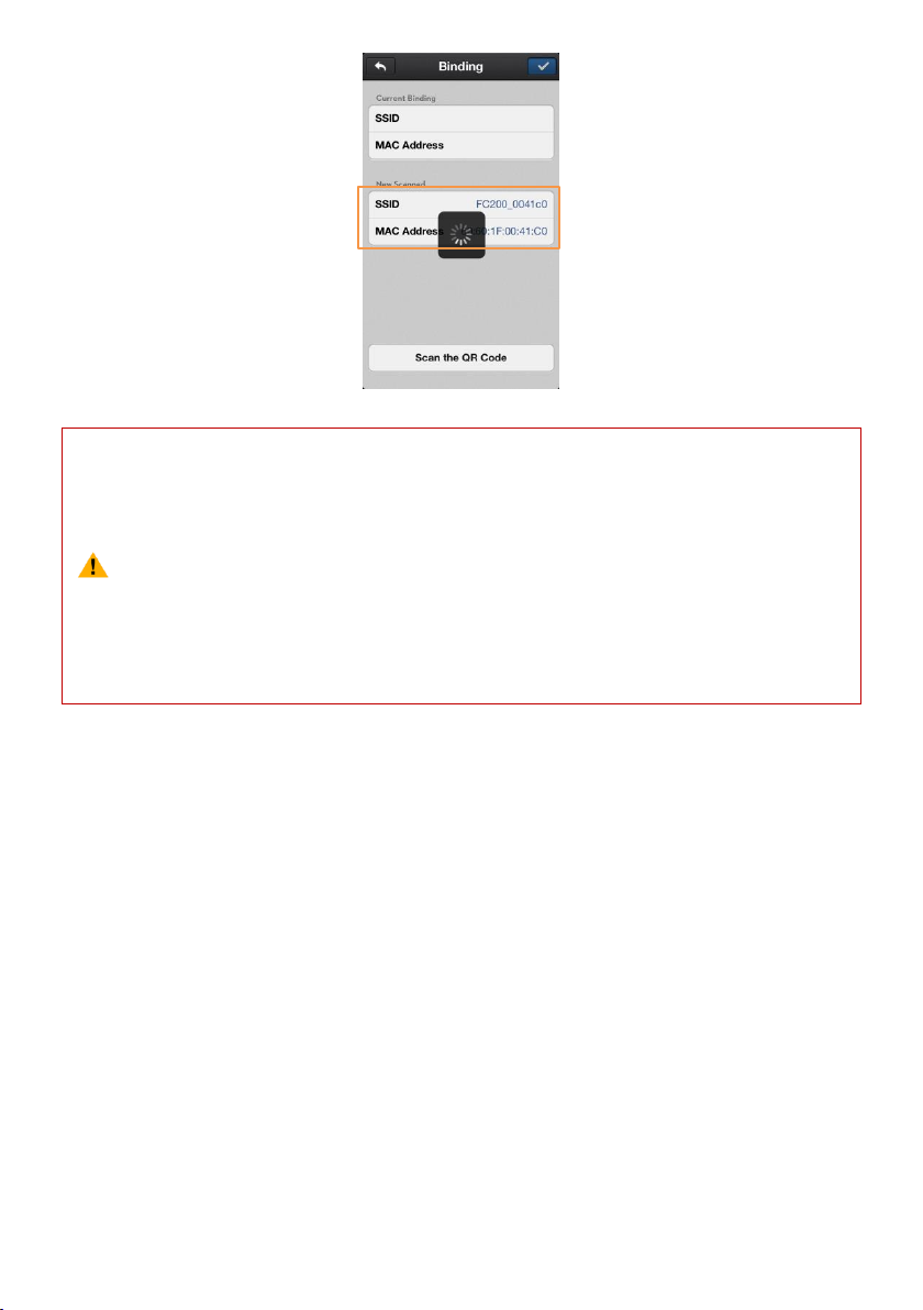
Fig.3
(1)
(2)
(3)
If both the camera and range extender are powered on and working normally, you will be able to
find the SSID on the Wi-Fi list of the mobile device.
DO NOT push the reset button of the range extender unless you are ready to rebind the range
extender and the camera! This will unbind your camera and you must follow the steps above to
rebind.
The QR code is located on the packaging of the PHANTOM 2 VISION. If you cannot find the QR
code, please contact DJI customer service to receive the QR code related to your camera’s
serial number.
©2013 DJI Innovations. All Rights Reserved. 17 |
Page 18
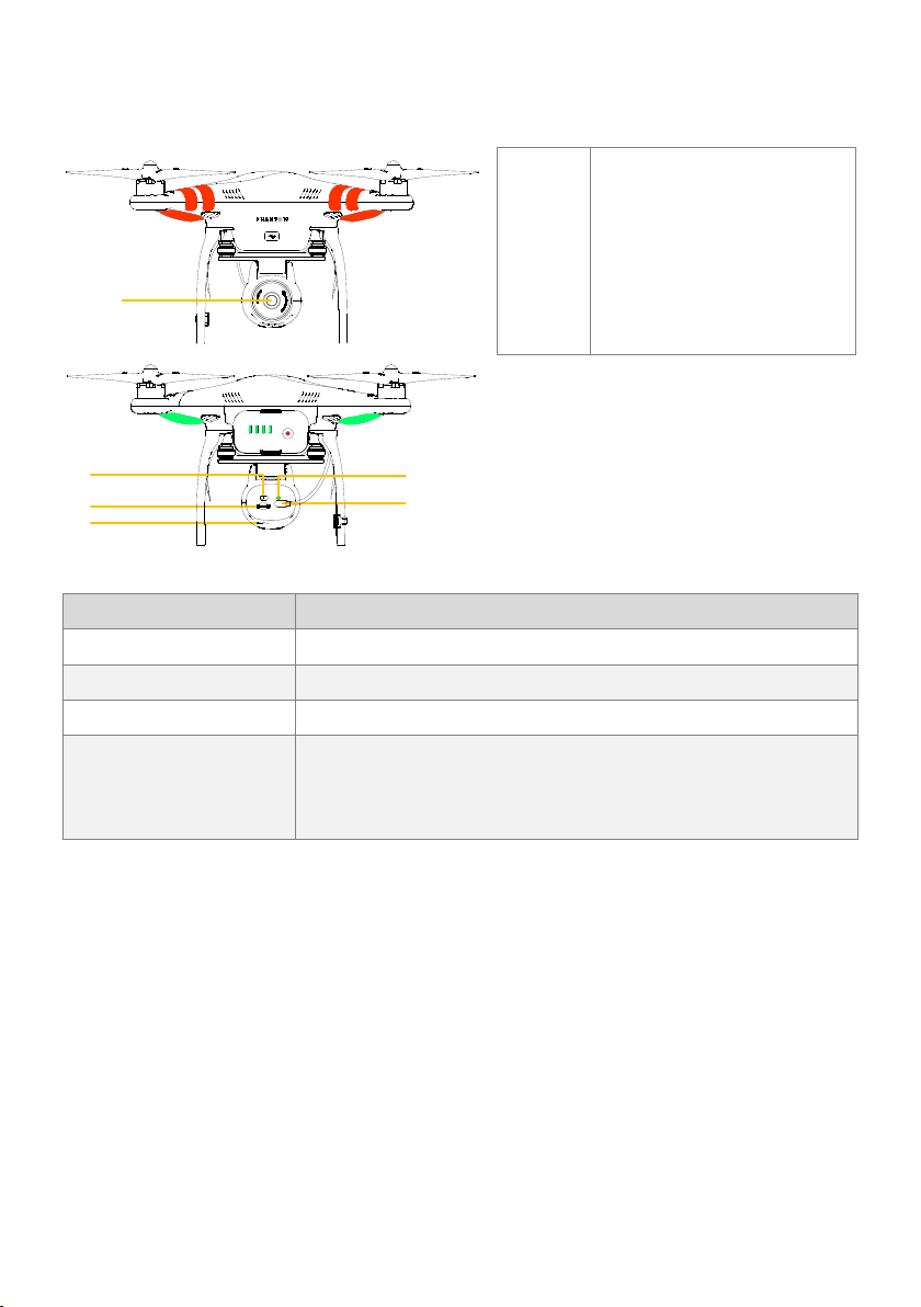
5 Preparing the Camera
[1]
[2]
[3]
[6]
OFF CAM ON WIFI ON
MICRO SD
[4]
[5]
[1]
[2]
[3]
[4]
[5]
[6]
Lens
Camera Power Switch
Micro-SD Card Slot
Camera Status Indicator
Camera Cable
Capture/Record Button
Camera Features
Specifications
Resolution
14 Megapixels
FOV
140°/ 120° / 90°
Sensor size
1/2.3”
Functions
Supports multi-capture, continuous capture and timed capture
Supports HD Recording (1080p30/1080i60)
Supports both RAW and JPEG photo formats
5.1 The built-in camera
5.2 Main Functions
[1] Lens
For viewing and photographing, with main parameters of f/2.8,FOV 140°.
Please remove the lens cover when the camera is in use and replace the cover for storage.
[2] Camera Power Switch (on the back of the camera)
Used to power the camera on and off.
OFF – Powered off.
CAM ON – Power on, Wi-Fi off.
WIFI ON – Power and Wi-Fi are both on. Make sure to switch to ‘WIFI ON’ and the range extender is powered
on if using the DJI VISION App.
©2013 DJI Innovations. All Rights Reserved. 18 |
Page 19

[3] Micro-SD Card Slot (on the back of the camera)
(1)
(2)
(3)
Maximum supported Micro-SD card capacity is 32GB.
The DJI VISION App may not be able to read the Micro-SD card prepared by the user. It is
suggested that you use the DJI VISION App to format the Micro-SD card when first used in the
camera.
Refer to the <Camera Settings> for Micro-SD card formatting details.
Camera indicator
Wi-Fi
Camera status
Solid
OFF
Power On; Idle State
Slow Blink (0.2s on, 1.8s off)
ON
Idle State
Fast Blink (0.1s on, 0.3s off)
ON
Synchronizing photos and videos
Solid
OFF
Recording
Blink Once (0.2s on, 0.3s off)
ON/OFF
Taking a single capture
Blink 3 Times(0.1s on, 0.1s off)
ON/OFF
Taking 3 or 5 photos per shot
Fast Blink (0.1s on, 0.3s off)
ON/OFF
Firmware Upgrading
(0.2s green, 1.8s yellow)
ON
Recording
Solid
ON/OFF
Critical error
Slow Blink (0.2s on, 1.8s off)
ON/OFF
CMOS sensor error
Blink Once (0.2s on, 0.3s off)
ON/OFF
Operation failed
Blink 3 Times(0.1s on, 0.1s off)
ON/OFF
Micro-SD Card error
Fast Blink (0.1s on, 0.3s off)
ON/OFF
Upgrade error
(0.5s green, 0.5s yellow, 0.5s red, 0.5s Off)
ON/OFF
Camera has overheated
When camera temperature rises above 80℃, the LED indicator will blink . The camera will
automatically power off if the temperature rises above 85℃.
Make sure that the Micro-SD card is inserted before you take any photos or record any videos.
[4] Camera Indicator (on the back of the camera)
The Camera Indicator is used to inform the user of the working status of the camera.
[5] Camera Cable (on the back of the camera)
Make sure that the camera cable is firmly attached to the camera before powering the camera on.
[6] Capture/Record Button (on the bottom of the camera)
Capture function: Press the button once (less than 2 seconds) to take a single capture.
Record function: Press the button once (greater than 2 seconds) to begin recording. Press once again to stop.
©2013 DJI Innovations. All Rights Reserved. 19 |
Page 20

5.3 Upgrading the Firmware of Camera
1.
2.
3.
4.
5.
6.
Download the latest firmware of camera from DJI website.
Copy the “firmware.bin” file to the root folder of your Micro-SD card.
Insert the SD card into the camera before turning it on.
Turn on the camera.
The firmware update will begin automatically. A yellow flashing LED indicates that the camera is updating.
When the yellow flashing disappears, the firmware has been updated. After a successful update, the
“firmware.bin” file’s name will change to “firmware.bin.bak00”. This file can now be deleted.
(1)
(2)
(3)
During the update, do not turn off the camera or take out the Micro-SD card. This may prevent
your camera from switching on and will need a factory reset.
A fast red flashing LED after the update means the update has failed. Please try again.
For the v1.1.8 version of the PHANTOM 2 VISION Camera, PAL support has been added to the
camera including 1080p25 and 960p25.
Follow the below instructions to update your firmware.
©2013 DJI Innovations. All Rights Reserved. 20 |
Page 21

6 Downloading and Installing the DJI VISION App
Download and install approaches
Approach 1
Scan the QR code to read the download link. Download and install the DJI VISION App on your
mobile device. You can find the QR code on the ‘Quick Start Guide’ as well as on the packaging of
the PHANTOM 2 VISION.
Approach 2
iOS user
Search “DJI VISION” from App Store, download and install on your mobile device.
Android user
Search “DJI VISION” from Google Play, download and install on your mobile device.
Supported mobile devices
iOS (iOS6 or above)
Recommended: iPhone4s, iPhone5, iPhone5s, iPhone5C, iPod Touch4, iPod
Touch5; Available but not recommended: iPAD3, iPAD4, iPAD mini.
Android (System 4.0 or above)
Samsung Galaxy S3, S4, Note2, Note3 or mobile devices of similar configuration.
DJI continues to support many mobile devices and any information from users are welcome. Please
send any questions or queries to the following mailbox: phantom2vision@dji.com.
Be aware that the DJI website regularly updates so make sure you visit often as well as the App Store
or Google Play in order to download the latest version of the DJI VISION App.
Access the Internet to register and login.
[1]
[2]
6.1 Download and Install
6.2 Register & Login
The App Welcome Page Registration Page Login Page
©2013 DJI Innovations. All Rights Reserved. 21 |
Page 22

[1] Register
(1)
(2)
You should login to your account the first time you use the DJI VISION App.
If you do have an account, but forgot the password, select the “Forgot password” to retrieve it.
[3]
Select ‘Register’ to enter the registration page. Fill in your Email and Password information and then select
to create a new account.
[2] Login
Select ‘Login’ to enter the login page. Fill in your registered Email and Password and then select to login.
[3] Usage tips
Useful tips will display when you enter the welcome page. Tap the screen to display the next useful tip.
©2013 DJI Innovations. All Rights Reserved. 22 |
Page 23

7 Preparing the Flight Battery
Before use, please read and follow the user manual, disclaimer, and the warnings on the battery.
Users take full responsibility for all operations and usage.
The intelligent battery is specially designed for the PHANTOM 2 VISION, with a battery capacity of 5200mAh,
voltage of 11.1v and charge-discharge management functionality. The battery should only be charged with the
charger provided by DJI. DJI does not take any responsibility for operation of any charger from a third party.
There are many features provided by the DJI charger:
Balance charge protection
Full charge protection
Short circuit protection
Output protection
Sleep protection
Overheating protection
1.
2.
3.
Connect the battery to the charger while the power is OFF.
Connect the charger to a wall socket. The charger indicator light will turn a solid red when it is charging.
Wait until the charger indicator turns solid green to which indicates that the battery is completely charged.
Charger Indicator
Charger indicator
Status of charge
Charging.
Completely charged.
7.1 Intelligent Battery and Charger Instructions
Intelligent Battery Charger
7.2 Charging Procedures
Wall socket
©2013 DJI Innovations. All Rights Reserved. 23 |
Page 24

7.3 Install the Battery
(1)
(2)
(3)
(4)
An incorrectly inserted battery may cause one of the following to occur:
Bad contact.
Unavailable battery information.
Unsafe for flight.
Unable to take off.
More battery information is available in the battery tab of the PHANTOM 2 VISION assistant software.
LED3
LED4
Battery Power Button
(Built-in Battery Power Indicator)
LED2
LED1
Battery Level Indicator
Push the battery into the battery compartment correctly as the following diagram shows. Make sure to push the
battery into the compartment until you hear a ‘click’ sound.
7.4 Battery Usage
(1) Checking the battery level: When the battery is powered off; pressing the battery power button once will
indicate the current battery level. Refer to < Battery Level Indicator Description> for details.
(2) Powering on: When the battery is powered off; press the battery power button once and then press and hold for
2 seconds to turn on the intelligent battery.
(3) Powering off: When the battery is powered on; press the battery power button once and then press and hold for
2 seconds to turn off the intelligent battery.
©2013 DJI Innovations. All Rights Reserved. 24 |
Page 25

Description of the Battery Level Indicator
Battery level indicator
Current battery level
LED1
LED2
LED3
LED4
On
On
On
On
87.5%~100%
On
On
On
Blinking
75%~87.5%
On
On
On
Off
62.5%~75%
On
On
Blinking
Off
50%~62.5%
On
On
Off
Off
37.5%~50%
On
Blinking
Off
Off
25%~37.5%
On
Off
Off
Off
12.5%~25%
Blinking
Off
Off
Off
0%~12.5%
Off
Off
Off
Off
<0%
It’s suggested you purchase a new battery after you have discharged your current battery over 300
times.
It’s recommended to charge and discharge the battery thoroughly once every 20 charge/discharge
cycles. Users should discharge the battery until there is less than 8% power left or until the battery can
no longer be turned on. Refer to the DJI VISION App for an exact readout of the battery percentage
level. You should then fully recharge the battery to maximum capacity. This power cycling procedure will
ensure the battery is working at its optimal level.
Turn the power OFF when you have finished flying and remove the battery from its compartment.
Take the battery out of the aircraft after every flight and store the battery in a safe and secure place.
Adhere to the notes for the battery in the disclaimer and regard safety as your first priority.
The battery should be charged in an environment that is between 10℃ to 40℃, and be discharged in an
environment that is between -20℃ to 60℃. Both charging and discharging should be in an environment
that the relative humidity is lower than 80%.
It’s suggested that you purchase a new battery if the current battery is swollen or damaged in any way.
Never try to recharge or fly with a battery that is swollen or damaged in any way.
Never charge the battery unattended. Always charge the battery on a non-flammable surface such as
concrete and never near any flammable materials.
The current battery level is shown during both the charging and discharging process. Refer to the following table
for details
7.5 Correct Battery Usage Notes
©2013 DJI Innovations. All Rights Reserved. 25 |
Page 26

8 PHANTOM 2 Aircraft
[1]
[2]
[7]
[3]
[4]
[5]
[6]
OFF CAM ON WIFI ON
MICRO SD
[8]
[9]
[11]
[12]
[11]
[10]
[1]
[2]
[3]
[4]
[5]
[6]
[7]
[8]
[9]
[10]
[11]
[12]
Propeller
Motor
Front Side
Front LEDs
Micro-USB
Vibration Absorber
Compass
LED Flight Indicators
DJI Intelligent Battery
Servo
Receiver Antenna
Landing Gear
The built-in flight control system is used to control the entire aircraft’s functions in flight such as Pitch (forwards
and backwards), Roll (left and right), Elevator (up and down) and Yaw (turn left or right). The flight controller
contains the MC (Main Controller), IMU, GPS, compass, receiver and LED indicators. The IMU (Inertial
Measurement Unit) has a built-in inertial sensor and a barometric altimeter that measures both attitude and
altitude. The compass reads geomagnetic information which assists the GPS (Global Position System) to
accurately calculate the aircrafts position and height in order to lock the aircraft in a stable hover. The receiver
is used to communicate with the remote controller and the MC acts as the brains of the complete flight control
system connecting and controlling all the modules together.
OFF CAM ON WIFI ON
MICRO SD
LED Flight Indicators
Battery Power Indicator
Front LEDs
8.1 The Aircraft
8.2 Built-in Flight Control System Instructions
8.3 LED Flight Indicators Description
After powering on the intelligent battery, the LED flight indicators light up to show the aircraft’s current status.
Front LEDs
The front LEDs are for indicating where the nose of the aircraft is. They light up solid red only after the motors have
started spinning.
©2013 DJI Innovations. All Rights Reserved. 26 |
Page 27

LED Flight Indicators Description
Normal status
LED flight indicators
Notes
Power On Self-Test
----
Warming Up
Aircraft cannot take off.
Ready to Fly
Slow blinking green.
Ready to Fly (non-GPS)
Slow blinking yellow.
Abnormal status
LED flight indicators
Remote Controller Signal Lost
Fast blinking yellow. Refer to <Failsafe
Function>.
1st Level Low Battery Capacity Warning
Slow blinking red.
2
nd
Level Low Battery Capacity Warning
Fast blinking red.
Not Stationary or Sensor Bias is too big
Keep aircraft stationary or perform
IMU calibration.
Error*
Cannot fly.
Compass Needs Calibration
Refer to <Calibrating the Compass>.
(1) The aircraft should be kept stationary on level ground before takeoff.
(2) Make sure the aircraft’s status is in Ready to Fly or Ready to Fly (non-GPS) mode before takeoff.
(3) If an error occurs (LED is solid red), please connect to the PHANTOM 2 VISION assistant software
for more detailed information.
NO.
Errors
Operation
1
IMU calibration is required.
Calibrate within the assistant software.
2
IMU is abnormal.
Should be repaired.
3
Compass is abnormal.
Should be repaired.
4
Remote controller’s mid-point is set
abnormally.
Refer to < How to solve large margin(s) mid
point error?>.
©2013 DJI Innovations. All Rights Reserved. 27 |
Page 28
9 Connecting to the Camera
1.
2.
3.
4.
5.
Power on the remote controller and the range extender.
Make sure the switch on the back of the camera is set to “WIFI ON” and then power on the PHANTOM 2
VISION.
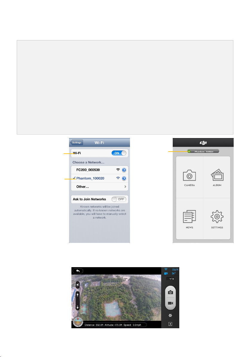
(Fig.1)Enable the Wi-Fi on your mobile device; wait for about 30 seconds, and then select the
Phantom_1xxxxx from theWi-Fi network list.
(Fig.2)Run the DJI VISION App on your mobile device which will indicate the current Wi-Fi connection
status on the main menu. The Wi-Fi connection indicator will turn solid green which means the connection
is good.
Tap the “CAMERA” icon and the DJI VISION App will establish a live camera preview (Fig.3). This means
everything is now functioning.
Wi-Fi Connection
Indicator
Enable the Wi-Fi
Select Phantom_1xxxxx
9.1 Camera Connection Procedures
Please carry out the following procedures to connect a mobile device to the PHANTOM 2 VISION.
Fig.1 Fig.2
©2013 DJI Innovations. All Rights Reserved. 28 |
Fig.3
Page 29

Wi-Fi Connection Indicator Description
Icon
Description
Solid green
Wi-Fi is now connected to the PHANTOM 2 VISION.
Solid blue
Wi-Fi is connected to another Wi-Fi network and NOT to the PHANTOM 2 VISION.
Off
No Wi-Fi connection.
(1)
(2)
The first time you launch the DJI VISION App, Internet access is required to finish the login
process or new account creation.
The SSID is unique for each PHANTOM 2 VISION which should appear in your Wi-Fi list as
Phantom_1xxxxx. Always connect to the SSID starting with Phantom_1xxxxx. FC200_0xxxxx is the
SSID of the camera and should not be connected to. If the SSID FC200_0xxxxx is connected to,
then the connection signal range will be extremely shortened.
©2013 DJI Innovations. All Rights Reserved. 29 |
Page 30

10 Calibrating the Compass
The compass is very sensitive to electromagnetic interference which causes abnormal compass data and leads
to poor flight performance or even flight failure. Regular calibration of the compass enables the compass to
perform at its optimal level.
(1)
(2)
(3)
DO NOT calibrate your compass where there is a possibility for the existence of strong magnetic
interference such as magnetite, parking structures, and steel reinforcement underground.
DO NOT carry ferromagnetic materials with you during calibration such as keys or cellular phones.
Compass Calibration is very important; otherwise the flight control system will not work properly.
Normal LED
Quickly flip the switch S1
360o Rotate the aircraft
horizontally
360oRotate the aircraft
vertically (Nose downward)
Position-1
Start horizontal calibration
Start vertical calibration
Succeed
Fail
Position-1->Position-3->Position-1
Flip 5 times
Start
cali
LED Flight Indicator
Position-1->Position-3->Position-1
Flip once
OFF CAM ON WIFI ON
MICRO SD
Position-3
LED Flight Indicator
LED Flight
Indicator
Re-calibrate
Position-1
Position-3
IMPORTANT: Make sure to perform the Compass Calibration procedures prior to the first flight.
10.1 Calibration Warnings
10.2 Calibration Procedures
Choose an open space to carry out the following procedures. Please watch the quick start video of the PHANTOM
2 VISION for more compass calibration details.
10.3 When Recalibration is Required
(1) When Compass Data is abnormal, the LED flight indicator will blink alternating between red and yellow.
(2) Last compass calibration was performed at a completely different flying field/location.
(3) The mechanical structure of the aircraft has changed, i.e. changed mounting position of the compass.
(4) Evident drifting occurs in flight, i.e. the aircraft doesn’t fly in straight lines.
©2013 DJI Innovations. All Rights Reserved. 30 |
Page 31

11 Flight
(1)
(2)
(3)
(4)
(5)
(6)
(7)
Before your first flight, please allow yourself some flight training (Using a flight simulator to
practice flying, getting instruction from an experienced person, etc.).
DO NOT fly in bad weather, such as rain or wind (more than moderate breeze) or fog.
The flying field should be open and void of tall buildings or other obstacles; the steel structure
within buildings may interfere with the compass.
Keep the aircraft away from obstacles, crowds, power lines, trees, lakes and rivers etc.
Try to avoid interference between the remote controller and other wireless equipment. (No base
stations or cell towers around)
The flight control system will not work properly at the South Pole or North Pole.
All parts must be kept out of the reach of children to avoid CHOKING HAZARDS; if a child has
accidentally swallowed any part, you should seek immediate medical assistance.
1.
2.
3.
4.
5.
6.
7.
Start by placing the PHANTON 2 VISION on the ground with the battery level indicator facing you.
Power on the remote controller.
Power on the range extender.
Switch the camera to the “WIFI ON” position.
Power on the aircraft by turning on the intelligent battery, refer to <Battery Usage> for details.
Connect the mobile device to the PHANTOM 2 VISION and then run the DJI VISION App to enter the
camera preview page.
Wait until the LED flight indicator starts to slowly blink green/yellow. This means the aircraft is initializing
and entering the “Ready to Fly”/“Ready to Fly (non-GPS).” state. Then proceed to execute the CSC
11.1 Flying Environment Requirements
11.2 Starting the Motors
A Combination Stick Command (CSC) is used to start the motors instead of simply pushing the throttle stick up.
This is a safety precaution to prevent the motors from accidentally spinning up. Push both sticks to their bottom
corners as indicated in the diagram below to start the motors. Once the motors have spun up, release both sticks
simultaneously. The same combination stick command (CSC) is used to stop the motors.
11.3 Takeoff/Landing Procedures
©2013 DJI Innovations. All Rights Reserved. 31 |
Page 32

8.
9.
10.
11.
command to start motors.
Push the throttle stick up slowly to lift the aircraft off the ground. Refer to <Remote Controller Operation
Mode> for more details.
Enjoy your flight while capturing and recording with the DJI VISION App. Refer to the<DJI VISION App
Usage> for more details.
Be sure you are hovering over a level surface. Pull down on the throttle stick gently to descend and land.
After landing the aircraft on the ground, keep the throttle stick at its lowest position for about 3 to 5
seconds which will automatically stop the motors.
You SHOULD NOT execute the CSC during normal flight! This will stop the motors and cause
the aircraft to descend rapidly and drop without any type of control.
(1)
(2)
(3)
When the LED flight indicator blinks yellow rapidly during flight, the aircraft has entered into
Failsafe mode, refer to <Failsafe Function> for details.
A low battery capacity warning is indicated by the LED flight indicator blinking red slowly or
rapidly during flight. Refer to the <Low Battery Capacity Warning Function> for details.
Watch the quick start video about flight for more flight information.
The aircraft will enter Failsafe mode when the connection from the remote controller is lost. The flight control
system will automatically control the aircraft to return to home and land to reduce injuries or damage. The
following situations would make the aircraft fail to receive a signal from the remote controller and enter Failsafe
mode:
(1) The remote controller is powered off.
(2) The aircraft has flown out of the effective communication range of the remote controller.
(3) There is an obstacle obstructing the signal between the remote controller and the aircraft, essentially
reducing the distance the signal can travel.
(4) There is interference causing a signal problem with the remote controller.
The flight control system will try to keep the aircraft level during descent and landing. Note that the aircraft may
be drifting during descent and landing process.
The flight control system will automatically control the aircraft to fly back to the home point and land.
11.4 Failsafe Function
Failsafe works differently depending on the mode the aircraft is in when Failsafe mode is initiated whether it is in
the Ready to Fly or Ready to Fly (non-GPS) mode.
Ready to Fly (non-GPS) ---- Automatic landing
Ready to Fly ---- Automatic go home and land
©2013 DJI Innovations. All Rights Reserved. 32 |
Page 33

Home Point
1 Record Home Point.
2 Flying.
3 Remote controller signal lost.
5 Fly back to home point.4 Signal lost lasts 3s, begin to go home.
6 Landing after hovering 15s.
LED Flight Indicator
à
OFF CAM ON WIFI ON
MICRO SD
OFF CAM ON WIFI ON
MICRO SD
OFF CAM ON WIFI ON
MICRO SD
OFF CAM ON WIFI ON
MICRO SD
OFF CAM ON WIFI ON
MICRO SD
OFF CAM ON WIFI ON
MICRO SD
OFF CAM ON WIFI ON
MICRO SD
LED Flight Indicator
LED Flight Indicator
LED Flight Indicator LED Flight Indicator LED Flight Indicator
Height over home point<=20m
Height over home point>20m
20m
Elevate to 20m
Switching the S2 of remote controller from upper most position to its bottom most position and back
to upper most position for 5 times or more will reset the home point of PHANTOM 2 VISION.
Definition of “home point” is i) where the PHANTOM 2 VISION return to when control signal is lost ii)
the home position which is used to calculate the horizontal distance between you and the aircraft
which is displayed on your cell phone app. When the home point is set, you will see a very short period
of fast green light flashing on the LED Flight Indicator.
Position of Switch S1
Position-1
Position-2
Position-3
How to regain control
When the S1 switch is switched to Position-1,
toggle the S1 switch to any other position once to
regain control. If remote controller’s signal is
recovered, control is returned back to the pilot.
Regain control as soon as signal
is recovered.
When the aircraft is initializing the Ready to Fly status, the aircraft will record the current GPS coordinates as the
home point. It is recommended to lift off only after Ready to Fly status is confirmed for the safety of being able to
fly back to home point successfully in case the Failsafe mode is initiated.
Go Home Procedures
Regaining Control During Failsafe Procedure
Failsafe on the DJI VISION App
The DJI VISION App will provide information during Failsafe.
©2013 DJI Innovations. All Rights Reserved. 33 |
Page 34

Control Signal Lost Indicator
Going Home Indicator
Refer to the <DJI VISION App Usage> for details.
The low battery capacity warning alerts users when the battery is close to depletion during flight. When it
appears, users should promptly fly back and land to avoid accidental damage. The PHANTOM 2 VISION has two
levels of low battery capacity warning. The first appears when the battery has less than 30% power and the
second when it has less than 15%.
When battery power drops below 30% an LED indicator will blink red slowly and an alert will show on the DJI
VISION app; refer to the <DJI VISION app Low Battery Capacity Warning>. At lower than 15% the LED indicator
will blink red rapidly and the DJI VISION app will sound an alarm; refer to the <DJI VISION app Low Battery
Capacity Warning>. The PHANTOM 2 VISION will also begin to descend and land automatically. After it has
landed, keep the throttle stick at its lowest point or execute CSC; refer to <Starting the Motors>.
If you push the throttle stick above the mid-point, the PHANTOM 2 VISION will ascend slowly. Use the throttle,
pitch, roll and yaw sticks normally to find a more appropriate landing area if required.
There is a hidden third low battery threshold in addition to the 1st and 2nd level warnings. This uses 10.65V as
its threshold. Both this voltage threshold and the 2nd Level Low Battery Warning will trigger auto-landing.
Altitude can be maintained if necessary by pulling up on the throttle.)
11.5 Low Battery Capacity Warning Function
DJI VISION App Low Battery Capacity Warning
DJI VISION App will show low battery capacity warnings.
(1) A red rectangle will blink on the camera screen.
(2) Audible alarm. Make sure the sound is turned on and volume is turned up on your mobile device.
(3) The aircraft battery icon will turn red.
©2013 DJI Innovations. All Rights Reserved. 34 |
Page 35

Low Battery Capacity Warning
Refer to the <DJI VISION App Usage> for details.
(1) Remember to fly your PHANTOM 2 VISION back as soon as you see a low battery capacity warning.
(2) The PHANTOM 2 VISION is "Ready To Fly," "Ready to Capture" and "Ready to Share" but it is still
an aircraft. Keeping the battery contact needles and pads clean is very important. Any dirt and dust
may cause a communication failure.
©2013 DJI Innovations. All Rights Reserved. 35 |
Page 36

12 DJI VISION App Usage
Icons
Description
Camera
Tap to enter camera preview
Album
Tap to enter Album
News
Tap to enter DJI news
Settings
Tap to enter App settings
(1)
(2)
(3)
Connect your mobile device to the PHANTOM 2 VISION Wi-Fi network to use the camera and
onboard album.
Connect your mobile device to the internet (mobile or Wi-Fi) to share photos, videos and read
DJI news.
If you receive a phone call during flight, the live camera preview screen may be interrupted. It's
recommended to ignore the call and pay full attention to your flight.
[1]
[2]
[3]
[4]
[5]
[6]
[7]
[8]
[9]
[10]
[11]
[12]
[13]
The DJI VISION App controls the PHANTOM 2 VISION camera including capture and recording, settings, pitch
angle adjustments, and displays essential status including flight parameters and battery life.
12.1 DJI VISION App Main Menu
After login you will come to the main page. This shows the current Wi-Fi connection and four app function icons.
12.2 Camera Page
Basic Use
©2013 DJI Innovations. All Rights Reserved. 36 |
Page 37

[1] Return
Normal Mode pitch control
Pitch movement
Accelerometer Sensor Mode Pitch Control
Pitch Movement
Accelerometer Sensor Mode Yaw Control
Yaw Movement
In Accelerometer Sensor Mode, the pitch angle indicator will show a grey area. When the green pitch
indicator is inside the grey area, the camera will move according to pitch gestures. When the indicator
reaches the boundary of the grey area, pitch gestures will control the camera’s pitch speed at
a constant rate.
- Return to the preview page
[2] Camera Tilt Control
- Tilt Control Mode. Tap and hold to enter the Accelerometer Sensor Mode. Release to return to normal
mode.
Normal Mode
Tap up arrow ( ) to pitch camera upwards and down arrow ( ) to pitch downwards. Green slider indicates
current camera pitch.
Accelerometer Sensor Mode
Tap and Hold to switch on Accelerometer Sensor Mode to control camera pitch and rotation by moving your
mobile device.
Tilt device forward to pitch camera downward and backward to pitch upward. Lean it left to rotate left( ) and
right to rotate right( ).
©2013 DJI Innovations. All Rights Reserved. 37 |
Page 38

[3] Flight Attitude and Radar Function
(1)
(2)
By default, the center of the radar indicates the home point that has been recorded by the
PHANTOM 2 VISION. Tap the center of the radar to switch the center to your mobile device's
current location.
If your mobile device contains a compass, the top portion of the Radar is the direction you are
pointing. If not, the radar will be oriented due north.
Distance will appear as NA if the PHANTOM 2 VISION is not Ready to Fly.
PHANTOM 2 VISION
Mobile Device Location
Distance
Home Point
Flight attitude is indicated by the flight attitude icon.
(1) The red arrow shows which direction the PHANTOM 2 VISION is facing.
(2) Blue and brown areas indicate its pitch.
(3) Tilting of the brown and blue area shows roll angle.
Tap the flight attitude icon to turn on the radar function. Home is located in the center of the radar and the red
icon indicates the PHANTOM 2 VISION’s current heading, direction, and approximate distance from home.
Tap the flight attitude icon again to disable the radar.
[4] Flight Parameters
Distance: Horizontal distance from home point.
Altitude: Vertical distance from home point.
Speed: Horizontal flying speed.
[5] Wi-Fi Signal Intensity
Indicates camera is connected to your mobile device and Wi-Fi is working normally.
The connection between the camera and mobile device may fail if Wi-Fi signal strength is low. Refer to the
<PHANTOM 2 VISION CONNECTION BROKEN>on the camera page.
©2013 DJI Innovations. All Rights Reserved. 38 |
Page 39

[6] Aircraft Battery Level
The available power thresholds mentioned above can be adjusted in the PHANTOM 2 VISION
assistant software.
(1)
(2)
Shutter button is disabled during video recording.
Capture modes can be reconfigured in camera settings; refer to the <Camera Settings>.
(1) When available power is more than 30%, the battery icon is blue (e.g. ). This battery level is appropriate
for flight.
(2) When below 30%, the battery icon will turn red (e.g. ) and the LED flight indicator will slowly blink red.
This battery level is low for flight. It is recommended that you fly your PHANTOM 2 VISION home and land
it as soon as possible.
(3) After available power drops below 15% (e.g. ), there is no longer enough power for flight. The LED flight
indicator will begin to flash red rapidly and the PHANTOM 2 VISION will begin an automatic descent and
land.
[7] Aircraft GPS Status
Displays GPS status and the number of available satellites. The icon is highlighted when more than 6 satellites
are found, enabling Ready to Fly mode.
[8] Micro-SD Card Status
Displays Micro-SD Card Status. The icon is highlighted when a valid Micro-SD card is inserted. If there is no
Micro-SD card present, it is grayed out.
[9] Remaining Shots
Displays estimated shots remaining, based on the current Photo Size setting of camera and the storage capacity
of the Micro-SD card. This shows ‘0’ if:
(1) Micro-SD card is not inserted.
(2) Micro-SD card is full.
(3) Micro-SD card is damaged.
(4) Connection between the DJI VISION App and camera is broken.
[10] Shutter Button
Tap to take photos.
Single capture: press once for a single capture.
Continuous capture: press once for 3 or 5 captures.
Timed capture: press once to begin a timed capture, press again to stop.
©2013 DJI Innovations. All Rights Reserved. 39 |
Page 40

[11] Record Button
Single capture.
3 captures.
5 captures.
Timed capture. Also selectable:
a) Intervals between two shots (3~60 s)
b) Number of shots (2~254, or infinite shots
until Micro-SD card is filled)
Capture Button will change according to the selected capture mode. ( , , , .)
[1]
[2]
[3]
[4]
[5]
[6]
[7]
[8]
[9]
[10]
[11]
[12]
Start and Stop video recording. Tap once to start recording. A red dot will blink to indicate recording is in
progress and a time elapsed counter will appear in the top right corner of the preview screen. Press again to
stop recording.
[12] Camera Settings
Tap to open the camera settings menu, refer to <Camera Settings>.
[13] Hide or Show Flight Parameters.
Tap to hide the flight parameters. Tap again to show.
Camera Settings
[1] Capture Mode
©2013 DJI Innovations. All Rights Reserved. 40 |
Page 41

[2] Photo Size
Large: 4384 x 3288, 4:3, 14.4MP
Medium: 4384 x 2922, 3:2, 12.8MP
Small: 4384 x 2466, 16:9, 10.8MP
1920 x 1080 60i,
16:9
1920 x 1080 30p,
16:9
1920 x 1080 25p,
16:9
1280 x 960 30p,
4:3
1280 x 960 25p,
4:3
1280 x 720 60p,
16:9
1280 x 720 30p,
16:9
640 x 480 30p,
4:3(VGA)
Three Field of View (FOV) options are supported when shooting in 1920x1080 60i, 1920x1080 30p and
1920x1080 25p: Wide (140°), Medium (120°) and Narrow (90°).
JPEG
RAW
The PHANTOM 2 VISION camera shoots in JPEG and RAW file
formats simultaneously when this option is selected. See the following
table for detailed specifications.
JPEG photo size
4384 X 3288
4384 X 2922
4384 X 2466
RAW photo size
4384 X 3288
4384 X 2920
4384 X 2464
RAW is not supported in continuous capture mode or timed capture mode. JPEG photos will be created
automatically.
RAW format support will be coming soon with DJI Conversion Software to convert PHANTOM 2 VISION’s
Camera RAW files to Adobe DNG.
AUTO
100
200
[3] Video Resolution
[4] Photo Format
[5] Selectable ISO
©2013 DJI Innovations. All Rights Reserved. 41 |
Page 42

400
AWB (auto)
Sunny
Cloudy
Indoor
Center
Average
Spot
-2.0(EV)
2.0(EV)
-1.7(EV)
1.7(EV)
-1.3(EV)
1.3(EV)
-1.0(EV)
1.0(EV)
-0.7(EV)
0.7(EV)
-0.3(EV)
0.3(EV)
0(EV)
Standard
Hard
Soft
Auto
50Hz
60Hz
[6] White Balance
[7] Exposure Metering
[8] Exposure Compensation
[9] Sharpness
[10] Anti-flicker
[11] Restore Default Settings
Restores all camera default settings. Camera reboot is needed to allow restoration to take effect.
©2013 DJI Innovations. All Rights Reserved. 42 |
Page 43

[1]
[4]
[3]
[2]
[12] Format SD Card
Format the Micro-SD card. All data stored in the Micro-SD card will be lost after formatting. Remember to
backup before formatting.
12.3 Album Page
Camera SD CARD Album
Browse thumbnails of photos and videos stored on the Micro-SD card. Tap to view photo or watch video.
[1] Photos and Videos are listed and grouped by date.
[2] All photos and videos that have already been synced to your mobile device are identified with the icon.
[3] Tap any thumbnail for single view mode. Tap a Photo thumbnail that hasn’t been synchronized to the mobile
device to view the photo. Swipe left or right to view the previous or next photo item. Tap on a video thumbnail
to play it and view the video’s length. A progress bar will also appear at the bottom of the screen. Tap to
the same time.
enter single synchronization mode to synchronize a single photo or video, or to synchronize and play a video at
[4] Tap the button to enter multiple synchronization mode (as shown in the following diagram). Tap thumbnails
©2013 DJI Innovations. All Rights Reserved. 43 |
Page 44

to select photos or videos to synchronize to your mobile device (The thumbnails identified by the check mark
Some mobile devices may fail to support synchronization of 1080i60 video files.
Select a group
Select a single
photo or video
[5]
[1]
[2]
[3]
[4]
are successfully selected.). Or you can select one or more groups to be synchronized by checking the box
before the group, and then Tap to start synchronizing. During the synchronization process, users can tap
to cancel the synchronization. Photos and videos that have been synchronized to the mobile device will
remain.
[5] Tap “Cancel” or “Finished” to exit the multiple synchronization mode and return to the SD CARD page.
Mobile Device Album
[1] You can browse all photos and videos in the album which have been synchronized to the mobile device, view a
selected photo or play a selected video.
©2013 DJI Innovations. All Rights Reserved. 44 |
Page 45

[2] Photos and videos are listed in thumbnail style and sorted by capture time.
Access to the Internet is required to load a map.
Access to the Internet is required to share your photos and videos.
[5]
Geo-tagged locations
[3] Pictures and videos are sorted by captured/recorded Geo-tagged locations.
[4] Tap any thumbnail for single view; you can slide left or right to view the previous or next photo. Tap a video
thumbnail to play a single video.
[5] Tap to share your photos and videos to social network sites.
12.4 News Page
View the latest DJI news. (Internet access is required.)
©2013 DJI Innovations. All Rights Reserved. 45 |
Page 46

12.5 Settings Page
[1]
[2]
[3]
[4]
[5]
[6]
[7]
[8]
[9]
[10]
[11]
[12]
[13]
[14]
News List News Details
[1] Toolbar Auto Hide
Slide the switch from left to right to enable this function. The toolbar will auto hide on the camera page.
[2] When Connection Breaks
©2013 DJI Innovations. All Rights Reserved. 46 |
Toolbar Auto Hide Disabled Toolbar Auto Hide Enabled
Page 47

[15]
[16]
[15] Stop Recording:
Enabled: Stop recording when the Wi-Fi connection between the mobile device and the camera breaks while
the camera is recording.
Disabled: Keep recording when the Wi-Fi connection between the mobile device and the camera breaks while
the camera is recording.
[16] Select the state the camera will enter in the event of a Wi-Fi Connection break between the mobile device and
the camera. Use this function to ensure you continue to capture the scenes you don’t want to miss during a
flight.
[3] Camera Settings Display
For iOS users, an enabled item will display in the camera settings toolbar, while a disabled item will be hidden.
For Android users, there is no this item.
[4] Preview Quality
©2013 DJI Innovations. All Rights Reserved. 47 |
Page 48

High: 640 x 480@15fps
Medium: 320 x 240@30fps
Low: 320 x 240@15fps (Recommended when there is a lot of interference.)
[5] Parameter Unit
Select imperial or metric units of measurement.
[6] Auto Flips
The user interface of the DJI PHANTOM 2 VISION App will flip if the mobile device’s auto-flip is enabled.
[7] Low Battery Warning
If enabled, an alarm will sound when the battery level is too low. Be sure sound is enabled on the mobile device
and try to adjust the volume to the highest level.
[8] Tutorial
Usage tips will be displayed.
[9] Clear News Cache
Tap to clear news cache.
[10] Binding
In the event the camera and range extender bind is lost or one of them requires repair or replacement, camera
and range extender binding should be performed via the DJI VISION App. Refer to the <How to Perform a
Camera & Range Extender Binding > for details.
[11] Find My PHANTOM 2 VISION
©2013 DJI Innovations. All Rights Reserved. 48 |
Page 49

My location
VISION’
Satellite Mode
Standard Mode
My location
S location
PHANTOM 2
VISION’
S location
[12] Account
Tap to see user’s account information.
[13] Rate
Tap to rate the DJI VISION App. Internet access is required.
[14] About
Tap to see the current version of the DJI VISION App and also for contact information.
©2013 DJI Innovations. All Rights Reserved. 49 |
Page 50

13 Assistant Software Installation and Configuration
1. Download
2.Connect
3.Install Driver
4.Install Software
Download the driver
installer and assistant
software installer
from the DJI website.
Connect the Micro-USB
port of PHANTOM 2
VISION to a USB port of
PC via a Micro-USB cable.
Run the driver
installer and follow
the prompts to
finish installation.
Run the assistant
software installer and
follow the prompts
to finish installation.
The PHANTOM 2 VISION Assistant software currently only supports Windows operating systems (Win
XP, Win7, Win8 (32 or 64 bit)).
1.
2.
3.
4.
Start up the PC, power on the PHANTOM 2 VISION, then Connect the PHANTOM 2 VISION to the PC
with a Micro-USB cable. DO NOT disconnect until configuration is finished.
Run the PHANTOM 2 VISION Assistant Software and wait for the PHANTOM 2 VISION to connect to the
Assistant Software. Observe the indicators on the bottom left of the screen. When connected
successfully, the connection indicator is and communication indicator is blinking .
Choose [Basic] or [Advanced] configuration pages.
View and check the current configuration in the [View] page.
Language swap
View configurations
Connection indicator
Communication
indicator
RC, Gain
Gimbal, Battery
IMU calibration
Firmware upgrade
Account, software
version
*This image is for reference
only. Please refer to the
actual user interface.
Function switch between PHANTOM
2 VISION and NAZA-M
(1) Users should not enable the Naza-M function before finishing the “Advanced Flight Maneuvers”
procedure, in accordance with the "Phantom Pilot Training Guide”. If the Naza-M function is
enabled, users can switch the control mode to either the ATTI. Mode, GPS Mode or Manual Mode,
13.1 Installing the Driver and Assistant Software
The PHANTOM 2 VISION Assistant software and the PHANTOM RC Assistant software are used for advanced
adjustments of the PHANTOM 2 VISION. Please follow the steps below to install the Driver and Assistant software.
13.2 Using the PHANTOM 2 VISION Assistant Software on a PC
©2013 DJI Innovations. All Rights Reserved. 50 |
Page 51

and access the advanced settings (e.g. IOC). In addition, the LED located on the rear frame arms
will display the flight status according to the Naza-M's indicator, instead of the Phantom 2 Vision's
indicator. Do not enable the Naza-M function unless you are an experienced user or guided by a
professional.
(2)You can change to the Phantom 2 Vision function by tapping the same button if the Naza-M
function is enabled. This operation will disable the Naza-M function and enable the Phantom 2
Vision function. All parameters will be returned to factory settings.
1.
2.
3.
An internet connection is required to upgrade the PHANTOM 2 VISION’s firmware.
Click the [Upgrade] icon to check the current firmware version and whether the installed firmware is the
latest version. If not, click the relative links to upgrade.
Be sure to wait until the Assistant software shows “finished”. Click OK and power cycle the PHANTOM 2
VISION after 5 seconds. Once completed, the firmware is up to date.
Firmware upgradable items
Current firmware version
Upgrade link
*This image is for reference
only. Please refer to the
actual user interface.
(1)
(2)
DO NOT power off until the upgrade is finished.
If the firmware upgrade failed, the main controller will enter a waiting for firmware upgrade
status automatically. If this happens, repeat the above procedures.
(1)
(2)
(3)
Firmware upgradable items:
Main Controller
GPS
5.8G Receiver
13.3 Firmware upgrade of the PHANTOM 2 VISION
Please follow the procedures to upgrade the software and firmware; otherwise the PHANTOM 2 VISION might not
work properly.
©2013 DJI Innovations. All Rights Reserved. 51 |
Page 52

(4)
(5)
P330CB (Main Board)
Battry
1.
2.
3.
4.
5.
Turn off the remote controller and find the Micro-USB port on the back of it. (If there is no one, users
should open the rear cover to find the Micro-USB port on the board inner the remote controller.)
Start up the PC, power on the remote controller, and then Connect the remote controller to the PC with a
Micro-USB cable. DO NOT disconnect until the configuration is finished.
Run the PHANTOM RC Assistant Software and wait for the remote controller to connect to the Assistant
Software. Observe the indicators on the bottom left of the screen. When connected successfully,
the connection indicator is and communication indicator is blinking .
Finish configuration in the [Main] page.
Finish upgrade in the [Info] page if necessary.
Language swap
Main page
Connection indicator
Communication indicator
Firmware upgrade
Account, software
version
*This image is for
reference only. Please
refer to the actual
user interface.
13.4 PHANTOM RC Assistant Software Description
Please follow the procedures to finish the configuration of the remote controller.
©2013 DJI Innovations. All Rights Reserved. 52 |
Page 53

14 Troubleshooting(FAQ)
14.1 How to solve large margin(s) mid-point error?
If the Remote Controller stick(s) mid-point margin of error is too big, the motors will fail to start when you execute
the Combination Stick Commands (CSC) and the aircraft will not take off. Below are possible situations where the
Remote Controller’s stick(s) mid-point margins of error could be too big:
(1) One of the Remote Controller’s stick position (except the throttle stick) is not centered when powering on the
PHANTOM 2 VISION.
Solution: Place all Remote Controller sticks at their mid-point positions and then power cycle the PHANTOM 2
VISION to re-record the mid-point. If the problem persists, this can be caused by scenario (2).
(2) The Remote Controller sticks have been trimmed which leads to a large deviation of the mid-point position.
Solution: Use the Assistant Software to perform a Remote Controller calibration. To do so, carry out the following
procedures.
(a) Connect to the Assistant software, tap Basic-> RC-> Command Sticks Calibration, and push all Remote
Controller sticks through their complete travel range to see if any stick cannot reach its outer most position.
(b) Power cycle the PHANTOM 2 VISION. Note that a power cycle is required.
(c) Redo the Remote Controller calibration according to the Assistant software.
If the above solutions do not solve your issue, please send your Remote Controller to DJI Customer service for
repair.
14.2 How to restore a video file if power is turned off during a recording session?
Solution: Keep or place the Micro-SD card back into the camera. Power cycle the camera and wait about 30
seconds for the video file to be restored.
14.3 Failure to acquire the SSID.
Solution: Double check whether both the camera and Range Extender are powered on and the power switch of the
camera is switched to “WIFI ON.”
14.4 What to do if PHANTOM 2 VISION is out of sight and the Wi-Fi connections is lost?
Solution: Turn off the Remote Controller to trigger the Failsafe mode and the aircraft will start to fly back, descend,
and land at the Home point automatically. Please make sure there are no obstacles within the go home route and
you are familiar with the regaining control procedure.
14.5 Wi-Fi connection fails all the time.
Solution: Double check the current Wi-Fi connection status of the mobile device. The mobile device may be
connecting to other Wi-Fi networks after a connection breaks with the PHANTOM 2 VISION.
©2013 DJI Innovations. All Rights Reserved. 53 |
Page 54

14.6 Files fail to synchronize.
Solution: Video files that are too large (file sizes close to 4GB) cannot be synchronized to the mobile device. Some
mobile devices also fail to support synchronization of the 1080i60 video files.
14.7 Albums fail to synchronize.
Solution: Reset the settings of your mobile device as illustrated below. Enable the Settings ->Private->Photos->DJI
VISION. Otherwise the Albums will fail to synchronize with your mobile device.
14.8 Failure to share.
Solution: Please make sure the mobile device has access to the Internet.
14.9 Some mobile Android devices have a problem connecting to the PHANTOM 2 VISION
Wi-Fi Extender.
Solution: Some mobile Android devices do not allow for both a Wi-Fi connection and a mobile data connection at
the same time. When trying to connect to the PHANTOM 2 VISION Wi-Fi network, most devices will check whether
an Internet connection has a certain Wi-Fi setting enabled, e.g. Auto network switch or Test for Internet connection.
If no Internet connection is found because the PHANTOM 2 VISION creates a non-routable connection it will drop
the PHANTOM 2 VISION Wi-Fi network connection and scan for the next available connection. Example: For the
Samsung Note 3, carry out the following procedures to solve this issue. Tap Settings -> Wi-Fi, and then tap the
“Menu” button. Select “Advanced” then uncheck the “Auto network switch”. You might see a warning that indicates
the Internet connection is unstable but just ignore this message.
©2013 DJI Innovations. All Rights Reserved. 54 |
Page 55

14.10 Usage tips for the App used on multiple mobile devices.
During flight, if you use the App on multiple mobile devices, please turn off the App on the first mobile device, and
then turn on the App on the second one to ensure the App can work normally on the second mobile device.
14.11 How to land the aircraft smoothly in a better way?
First pull the throttle stick position down to lower than 5%, then execute the CSC command to stop the motors.
14.12 Why the discharge times of a new battery not at zero?
A battery aging test is performed prior to delivery which affects the discharge time of the new battery. This is why
the discharge time of a new battery is not zero. The battery is okay to use.
©2013 DJI Innovations. All Rights Reserved. 55 |
Page 56

15 Appendix
Normal status
LED Flight Indicators
Power On Self-Test
Warming Up
Ready to Fly
Ready to Fly (non-GPS)
Warning and Error
LED Flight Indicators
Remote Controller Signal Lost
1st Level Low Battery Capacity Warning
2nd Level Low Battery Capacity Warning
Not Stationary or Sensor Bias is too big
Error*
Compass Needs Calibration
LED Flight Indicator Status
*You can figure out the error by connecting the PHANTOM 2 VISION to the PHANTOM 2 VISION’s Assistant
Software.
©2013 DJI Innovations. All Rights Reserved. 56 |
Page 57

Specifications
Aircraft
Supported Battery
DJI 5200mAh Li-Po Battery
PHANTOM 2 VISION Weight
1160g
Hovering Accuracy (Ready to Fly)
Vertical: 0.8m; Horizontal: 2.5m
Max Yaw Angular Velocity
200°/s
Max Tilt Angle
35°
Max Ascent / Descent Speed
6m/s
Max Flight Speed
15m/s (Not Recommended)
Wheelbase
350mm
Tilting Range of Gimbal
0° - 60°
Remote Controller
Operating Frequency
5.728 GHz-5.85 GHz
Communication Distance (open area)
CE Compliance: 300m; FCC Compliance: 500m
Receiver Sensitivity (1%PER)
-93dBm
Transmitting Power (EIRP)
CE Compliance: 25mW; FCC Compliance: 125mW
Working Current/Voltage
80 mA@6V
Battery
4 AA Batteries
Camera
Resolution
14 Megapixels
FOV
140°/ 120° / 90°
Sensor Size
1/2.3”
Functions
Supports multi-capture, continuous capture and timed capture
Supports HD Recording (1080p30,1080i60)
Supports both RAW and JPEG photo formats
Range Extender
Operating Frequency
2412MHz - 2462MHz
Communication Distance (open area)
300m
Transmitting Power
17dBm
Power Consumption
1.5W
DJI VISION App
Supported Mobile Devices
Recommended: iPhone4s, iPhone5, iPhone5s, iPhone5C, iPod
Touch4, iPod Touch5;
Available but not recommended: iPAD3, iPAD4, iPAD mini.
Samsung Galaxy S3, S4, Note2, Note3 or phones of similar configuration.
System Requirement of Mobile Device
iOS 6.0 or above; Android system 4.0 or above
©2013 DJI Innovations. All Rights Reserved. 57 |
 Loading...