

Page 1

PHANTOM Quick Start Manual V1.7
2013.09.25 Revision
For NAZA-M Firmware V3.12
& Assistant Software V2.12
Thank you for purchasing our product. Please visit the DJI website, PHANTOM section to confirm if the printed manual
is the latest one according to the manual version. If not, please download and refer to the latest manual.
Please read the entire manual strictly and follow these steps to use you product. The manual will get you ready to fly by
doing simple operations. You can get an advanced manual from DJI website to learn more about PHANTOM, for
example, configuring parameters by connecting to assistant software, changing the transmitter to Mode1, matching
frequency between the transmitter and the receiver, etc.
Make sure to use the NAZA-M assistant software of 2.0 version (or above 2.0) to carry out firmware upgrade and
parameter configuration. DO NOT use the NAZA-M assistant software bellow 2.0 version.
Note: The built-in autopilot system is NAZA-M; you can obtain the current NAZA-M Firmware Version according to the
Assistant Software. If you ever upgrade your NAZA-M Firmware, please carefully read the corresponding NAZA-M
release note and NAZA-M quick start guide.
www.dji.com
©2012-2013 DJI Innovations. All Rights Reserved. 1 |
Page 2

Content
CONTENT .................................................................................................................................................. 2
DISCLAIMER & WARNING ................................................................................................................. 3
CAUTIONS FOR PRODUCT USE ..................................................................................................... 4
TRADEMARKS .......................................................................................................................................... 4
BATTERY USAGE & CHARGING CAUTIONS ............................................................................ 5
IN THE BOX ............................................................................................................................................... 6
REQUIRED ITEMS ................................................................................................................................... 6
INTRODUCTION ..................................................................................................................................... 7
AIRCRAFT & TRANSMITTER BASIC OPERATION................................................................... 8
BEFORE FLYING ..................................................................................................................................... 9
FLIGHT TEST ............................................................................................................................................ 13
THE FLOWCHART OF FAILSAFE AND HOW TO REGAIN CONTROL ....................... 14
LOW-VOLTAGE ALERT ...................................................................................................................... 15
LED DESCRIPTION ............................................................................................................................... 15
SPECIFICATIONS OF THE AIRCRAFT ......................................................................................... 16
©2012-2013 DJI Innovations. All Rights Reserved. 2 |
Page 3

Disclaimer & Warning
Please read this disclaimer carefully before using the PHANTOM. By using this product, you hereby agree to this
disclaimer and signify that you have read them fully. THIS PRODUCT IS NOT SUITABLE FOR PEOPLE UNDER THE
AGE OF 18.
PHANTOM is an excellent flight platform offering an excellent flight experience, only if it is powered normally and in a
good working condition. Despite the PHANTOM having a built-in autopilot system and our efforts in making the
operation of the controller as safe as possible when the main power battery is connected, we strongly recommend
users to remove all propellers when calibrating and setting parameters. Make sure all connections are good, and keep
children and animals away during firmware upgrade, system calibration and parameter setup. DJI Innovations accepts
no liability for damage(s) or injuries incurred directly or indirectly from the use of this product in the following
conditions:
1. Damage(s) or injuries incurred when users are drunk, taking drugs, drug anesthesia, dizziness, fatigue, nausea and
any other conditions no matter physically or mentally that could impair your ability.
2. Damage(s) or injuries caused by subjective intentional operations.
3. Any mental damage compensation caused by accident.
4. Failure to follow the guidance of the manual to assemble or operate.
5. Malfunctions caused by refit or replacement with non-DJI accessories and parts.
6. Damage(s) or injuries caused by using third party products or fake DJI products.
7. Damage(s) or injuries caused by mis-operation or subjective mis-judgment.
8. Damage(s) or injuries caused by mechanical failures due to erosion, aging.
9. Damage(s) or injuries caused by continued flying after low- voltage protection alert is triggered.
10. Damage(s) or injuries caused by knowingly flying the aircraft in abnormal condition (such as water, oil, soil, sand
and other unknown material ingress into the aircraft or the assembly is not completed, the main components have
obvious faults, obvious defect or missing accessories).
11. Damage(s) or injuries caused by flying in the following situations such as the aircraft in magnetic interference area,
radio interference area, government regulated no-fly zones or the pilot is in backlight, blocked, fuzzy sight, and
poor eyesight is not suitable for operating and other conditions not suitable for operating.
12. Damage(s) or injuries caused by using in bad weather, such as a rainy day or windy (more than moderate breeze),
snow, hail, lightning, tornadoes, hurricanes etc.
13. Damage(s) or injuries caused when the aircraft is in the following situations: collision, fire, explosion, floods,
tsunamis, subsidence, ice trapped, avalanche, debris flow, landslide, earthquake, etc.
14. Damage(s) or injuries caused by infringement such as any data, audio or video material recorded by the use of
aircraft.
15. Damage(s) or injuries caused by the misuse of the battery, protection circuit, RC model and battery chargers.
16. Other losses that are not covered by the scope of DJI Innovations liability.
©2012-2013 DJI Innovations. All Rights Reserved. 3 |
Page 4

Cautions for Product Use
Please check the following steps carefully every time before flight.
1. Before use of the product, please accept some flight training (Using a simulator to practice flying, getting
instruction from a professional person, etc.).
2. Check that all parts of the multi-rotor are in good condition before flight. Do not fly with aging or broken parts.
3. Check that the propellers and the motors are installed correctly and firmly before flight. Make sure the rotation
direction of each propeller is correct. Do not get close to or even touch the working motors and propellers to
avoid serious injury.
4. Do not over load the multi-rotor (should be less than 1200g).
5. Make sure that the transmitter battery and flight battery are fully charged.
6. Try to avoid interference between the remote control transmitter and other wireless equipment.
7. Make sure to switch on the transmitter first, then power on the multi-rotor before takeoff! Power off the
multi-rotor first, then switch off the transmitter after landing!
8. The fast rotating propellers of PHANTOM will cause serious damage and injury. Always fly the multi-rotor 3m or
above away from you and unsafe conditions, such as obstacles, crowds, high-voltage lines, etc. FLY
RESPONSIBLY.
9. All parts must be kept out of the reach of children to avoid CHOKE HAZARD; if a child accidentally swallows any
part you should immediately seek medical assistance.
10. Please always keep the compass module away from the magnet. Otherwise it may damage the compass module
and lead the aircraft to work abnormally or even be out of control.
11. DO NOT use the PHANTOM transmitter (receiver) with the other third party remote control equipment.
12. Make sure to use the NAZA-M assistant software of 2.0 version (or above 2.0) to carry out firmware upgrade
and parameter configuration. DO NOT use the NAZA-M assistant software bellow 2.0 version.
13. The built-in ESCs of PHANTOM ONLY support 3S (11.1V) power supply.
14. ONLY use the DJI original motor and 8-inch propeller.
15. If you want to put the PHANTOM in a car, please keep it away from the speaker, since the compass module may
be magnetized.
16. DO NOT use the magnetic screwdriver. Otherwise, keep the screwdriver at least 10cm away from the compass
module, to avoid magnetic interference.
17. If you use your own equipment(for example: GoPro3), please make sure the WiFi function is disabled, to avoid
the interference on the transmitter, which may cause the PHANTOM to FailSafe, crack and or even to fly away.
18. For Mac user, please install Windows Parallel to run assistant software.
If you have any problem you cannot solve during installation, please contact a DJI Authorized Dealer.
Trademarks
DJI and PHANTOM are registered trademarks of DJI Innovations. Names of product, brand, etc., appearing in this
manual are trademarks or registered trademarks of their respective owner companies. This product and manual are
copyrighted by DJI Innovations with all rights reserved. No part of this product or manual shall be reproduced in any
form without the prior written consent or authorization of DJI Innovations. No patent liability is assumed with respect to
the use of the product or information contained herein.
©2012-2013 DJI Innovations. All Rights Reserved. 4 |
Page 5

Battery Usage & Charging Cautions
1. Do not put the battery into water; store the battery in a cool and dry environment.
2. Only use the correctly specified batteries
3. Batteries must be kept out of the reach of children; if a child accidentally swallows the battery you should
immediately seek medical assistance.
4. Do not use or store the battery near fire.
5. Battery should be charged with proper standard charger.
6. Do not connect the battery reversed in positive and negative terminals in the charger or equipment.
7. Do not connect the battery directly to the wall plugs or vehicle-mounted socket.
8. Do not put the battery into a fire or heat the battery.
9. Do not let the battery terminals (+and-) touch together to cause short-circuit.
10. Do not transport or store the battery together with metal objects.
11. Do not hit or throw the battery.
12. Do not weld the battery terminals together.
13. Do not drive a nail in, hit with a hammer, or stomp on the battery.
14. Do not disassemble or alter the battery.
15. Do not use or store the battery in extreme heat environments, such as direct sunlight or in the car in hot weather.
Otherwise, the battery will overheat, may cause fire (or self-ignite), this will affect the performance of the battery,
shorten the service life of the battery.
16. Do not use the battery in strong electrostatic areas, otherwise the electronic protection may be damaged which
may cause a hazard.
17. If you get the battery electrolyte leakage into your eyes, don't rub, first wash your eyes with clean water then seek
medical assistance immediately. If not handled in a timely manner, eyes could be damaged.
18. Do not use the battery when it emits an odour, high temperature, deformation, change in colour or other
abnormal phenomena; if the battery is in use or charging, you should stop charging or using immediately.
19. If the battery terminal gets dirty, please clean it with a dry cloth before using. Otherwise it will cause a poor
contact, thus causing energy loss or inability to charge.
20. Discarded battery could lead to a fire; you should completely discharge the battery and wrap the output terminal
with insulating tape before discarding.
21. DO NOT drain the battery of phantom or leave the battery plugged into the PHANTOM when unused. When
there is low voltage alert please landing timely to avoid damages to the battery or others.
©2012-2013 DJI Innovations. All Rights Reserved. 5 |
Page 6
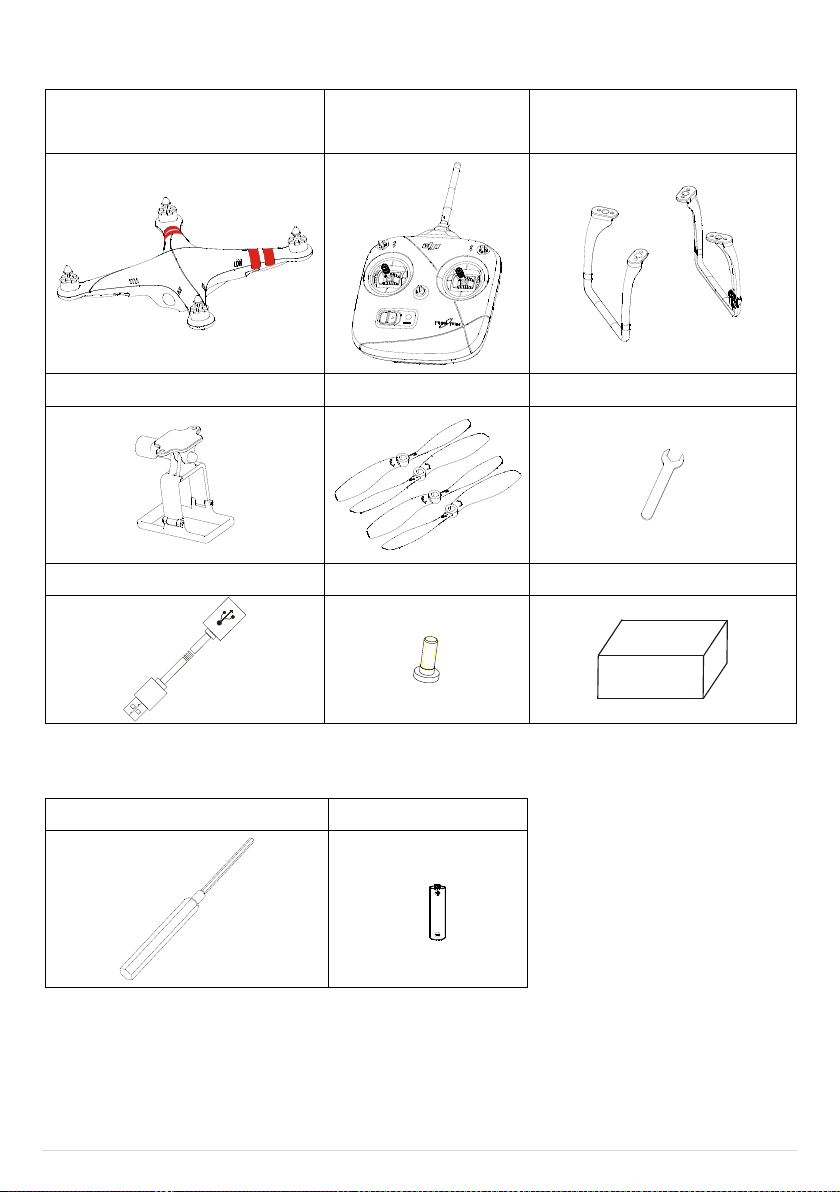
In the Box
Aircraft
Transmitter
Landing Gear
(with Compass Module)
Frame for Camera
Propellers
Assistant Wrench
USB Cable
Screw Package (M3x6)
Accessory
Phillips Screwdriver
5# AA Batteries
Required Items
©2012-2013 DJI Innovations. All Rights Reserved. 6 |
Page 7

Introduction
The PHANTOM is an all-in-one small Quad Copter designed for multi-rotor enthusiasts. Before shipping from the
factory, it has been configured and fully tested, which means you have no configuration to do.
Built-in
NAZA-M Autopilot System
(Refer to NAZA-M manual for details)
GPS & Compass Module
R/C Receiver
Power System for Flight
LED Indicator
USB Interface
(in the Battery Compartment)
Function
ATTI./GPS ATTI. Mode
Intelligent Orientation Control
Enhanced Fail-Safe
Low-Voltage Alert
Camera Frame (For GoPro)
Takeoff Weight:<1200g
OFF
CL
HL
GPS
ATTI
ATTI
Working Frequency: 2.4GHz ISM
Control Channel Numbers of Transmitter: 7
Communication Distance: 1000m
Receiver Sensitivity(1%PER): >-100dBm
Power Consumption of Transmitter:<20dBm
Working Current/Voltage: 52 mA@6V
AA Battery (5#): 4 Required
©2012-2013 DJI Innovations. All Rights Reserved. 7 |
Page 8

Aircraft & Transmitter Basic Operation
Transmitter
Aircraft
( is the nose direction)
GPS ATTI. Mode/ATTI. Mode
Throttle stick is for aircraft up& down control. The aircraft will hold
the height automatically if the stick is centered. You should Push
the throttle stick to the neutral position to take-off the multi-rotor.
Note that the stick returns to the central position when released
for the transmitter V3.5. For the version below 3.5, the stick
cannot hold the central position when released.
Yaw stick is for aircraft rudder control.
Command stick controls the angular velocity of the aircraft, with
the maximum rudder angular velocity of 200°/s. Left stick
command gives counter clock-wise rotation of the aircraft, & vice
versa.
Roll stick is for aircraft left/right control and Pitch stick is for
front/back control. Command stick controls the angle of the
aircraft. Stick neutral position is for 0˚, its endpoint is 35˚. The roll
and pitch sticks return to the central position when released.
In GPS Mode, the aircraft will hover (hold horizontal position)
when sticks released.
In ATTI. Mode, the aircraft will keep attitude stabilizing without
horizontal position (different from hover in GPS Mode).
GPS ATTI. ATTI. ATTI.
(Manual or
Failsafe is
selectable
in software.)
3-position switch (S1) on the Transmitter for mode control. Only
after Compass Module connection and Compass calibration, GPS
ATTI. Mode is available. Otherwise, all switch positions are for
ATTI. Mode. Pay attention because the GPS ATTI. Mode is
dependent on the number of GPS satellites acquired by the main
controller. Refer to the LED Indicator. When GPS signal has been
lost for 3s, system enters ATTI. Mode automatically. You can
enable the Manual Mode or FailSafe (also known as One-key
Go-home) in the assistant software->Basic->R/C->Control Mode.
OFF Course Lock Home Lock
3-position switch (S2) on the Transmitter for Intelligent
Orientation Control (IOC). Set the switch to OFF in basic flight.
This function is defaulted to off. If you want to use this function
refer to the advanced manual, and enable it in the assistant
software. Use IOC when you are familiar with basic flight.
You can change the operation mode of the Transmitter according to the advanced manual if necessary.
Definitions
Stick neutral position and stick released means the stick of Transmitter is pushed to the central position.
Command Stick means the stick of Transmitter is pushed away from the central position.
©2012-2013 DJI Innovations. All Rights Reserved. 8 |
Page 9

Before Flying
1. Open the battery compartment cover of the Transmitter.
2. Install 4x AA battery (5#) in accordance with the + /- pole.
3. Close the battery compartment cover of the Transmitter.
DO NOT use the PHANTOM transmitter (receiver) with the other third party remote control equipment.
Risk of explosion if replaced by an incorrect type.
Dispose of used batteries according to the instructions.
Remove the batteries after use.
When the voltage is lower than 4V, the transmitter will alarm with sound of “BB…………”, please change the
batteries.
1. First prepare the aircraft and the propellers (original 8-inch).
2. Assemble the propellers (the side with rotary mark facing up) to the aircraft. Make sure the rotary mark on the
propeller is the same as the mark on the frame arm. The arrow’s direction stands for the rotating direction of the
motors.
3. Finally fit the propeller nuts.
DO NOT use thread locker when mounting the propellers, just tighten the screws is enough.
1.
Installing the Transmitter Batteries
2.
Battery Charging – LiPo Battery
Please use the full charged battery of 3S LiPo.
(Recommended parameters: 733496 - 2200MAH-20C-11.1V.)
The built-in ESCs of PHANTOM ONLY support 3S (11.1V) power supply. DO NOT use the battery of higher voltage.
3.
Fitting the Propeller
©2012-2013 DJI Innovations. All Rights Reserved. 9 |
Page 10

4.
Landing Gear Mounting Compass Module Connecting
When flying, please make sure the compass module is stationary and firm.
If the Landing Gear with the compass module mount on has been deformed, please replace it with a new one and
mount it as the procedures above.
The compass module is not waterproof, and not anti-oil.
DO NOT use the magnetic screwdriver. Otherwise, keep the screwdriver at least 10cm away from the compass
module, to avoid magnetic interference.
1. Set the IOC and Control Mode switch to the top position.
2. Turn on the power switch of the Transmitter
Mount the Landing Gear with the Compass Module if Required
If the GPS ATTI. Mode is desired, you must first mount the landing gear which contains the Compass Module.
1. Prepare the aircraft and the landing gear.
2. Mount the landing gear with the Compass Module to the right part (shown as the following chart); make sure the
5-pin cable is through the hole of the landing gear. Fix the landing gear with screws (M3x6), and then connect the
5-pin cable to the Compass Module.
3. Mount the other landing gear to the left part.
4. Fix the antenna and the 5-pin cable on both landing gear by using the white adhesive tape.
5.
Turn on the Transmitter
©2012-2013 DJI Innovations. All Rights Reserved. 10 |
Page 11

6.
1. Place the aircraft on the ground
2. Open the battery compartment cover of the aircraft.
3. Put the battery into the compartment with the power cord facing outward.
4. Connect the battery and aircraft by the power lead and make sure the ESC’s work properly. (Correct sound)
5. Keep the sticks of the Transmitter and the Aircraft stationary until the system start and self-check has finished
( ).
6. Put the power cable into the battery compartment.
7. Close the battery compartment cover.
8. The LED may blink Yellow 4 times quickly ( ). Start motor is disable during LED blinking Yellow 4 times
quickly ( ), as the system is warming up.
Please contact your dealer if the “System start and self-check LED flashes” are not correct (Red LED appears in
the last four green flashes) in the Step5.
After the system start and self-checking has finished, if the LED blinks Red, Yellow and Green continually, that
means the IMU data is abnormal. The PHANTOM will not work, please connect to the Assistant Software and
follow the tips to do operation. If it blinks red and yellow lights alternately ( ), that means the
compass error is too big, it can be caused by the following three cases. Please connect to the Assistant Software,
select the “tools” tab and follow the tips of the “IMU Calibration” to do operation.
1. There are ferromagnetic substance around; first make sure that the compass has been calibrated correctly, you
can lift the aircraft up (about 1m from the ground), and stay away from the surrounding possible ferromagnetic
material object, if there is no red and yellow flashing after lifting it up about 1m from the ground, then it will not
affect the flight.
2. The compass module had been put near a magnet; in this situation please timely replace the compass for a new
one, otherwise it will lead to some abnormal action, or even loss of control.
3. The compass is not properly calibrated; in this situation please calibrate the compass correctly again, please see
the GPS compass calibration for details.
Power on the Aircraft
Notes
©2012-2013 DJI Innovations. All Rights Reserved. 11 |
Page 12

7.
1. Quickly switch the control mode switch from
ATTI. Mode
to
GPS ATTI.
Mode
and back to
ATTI. Mode
for 6 to 10 times, The LED indicator will turn
to constantly yellow.
2. Rotate your aircraft around the horizontal axis (about 360
o
) until the LED
changes to constant green, and then go to the next step.
3. Hold your aircraft vertically and rotate it (its nose is downward) around the
vertical axis (about 360o) until the LED turns off, meaning the calibration is
finished.
4. If the calibration was successful, calibration mode will exit automatically. If the
calibration has failed, the LED keeps flashing quickly Red. Switch the control
mode switch one time to cancel the calibration, and then re-start from step 1.
GPS ATTI. Mode
ATTI. Mode
ATTI. Mode->GPS ATTI. Mode ->
ATTI. Mode is one time,quickly
switch 6 to 10 times
Horizontal Rotation
Vertical Rotation
GPS & Compass Calibration
If the Compass Module is not used, you can skip this step.
The GPS module has a built-in magnetic field sensor for measuring the geomagnetic field, which is not the same in
different areas. The GPS module will not work unless the Compass Module has been connected. Make sure the
Compass Module connections are correct.
Please always keep the compass module away from the magnet. If this situation occurs please change the compass
module before flying. Otherwise it may damage the compass module and lead the aircraft to work abnormally or even
be out of control.
Calibrate the compass before the first flight or when flying in a different area. Make sure to keep away from
ferromagnetic substance and other electronic equipment when calibrating or flying. If you keep having calibration
failure, it might suggest that there is magnetic interference or other ferromagnetic substance, please avoid flying in this
area.
If you have calibration failure or the LED blinks red and yellow lights alternately ( ), please connect to
the Assistant Software, select the “Tools” tab and follow the tips of the “IMU Calibration” to do operation.
©2012-2013 DJI Innovations. All Rights Reserved. 12 |
Page 13

Flight Test
1. If in GPS ATTI. Mode, place the aircraft in an open space without buildings or trees. Take off the aircraft
after 6 or more GPS satellites are found (Red LED blinks once or no blinking). If in ATTI. Mode, you can skip
this step.
2. Place the aircraft 3 meters away from you and others, to avoid accidental injury.
3. Start-up
Switch on the transmitter first, then power on multi-rotor! Keep the aircraft stationary until the system
start and self-check has finished.
Please wait for the system to warm up gradually with the LED blinks Yellow 4 times quickly ( ). You
should not start the motors until the blinking disappears.
Keep the aircraft stationary, and execute the CSC to start the motors.
Release the yaw, roll and pitch sticks and keep them at the neutral position, at the same time raise t he
throttle stick from the bottom. The motors will stop if you do not push the throttle stick from the bottom
within 3 sec and you will need to re-start the motors.
Keep raising the throttle stick until all the rotors are working, push the throttle stick to the mid position
and then take-off your multi-rotor gently, pay attention not to push the stick excessively.
Pay attention to the aircraft movement at any time, and use the sticks to adjust the aircraft's position.
Keep the yaw, roll, pitch and throttle sticks at the mid position to hover the aircraft at desired height.
4. Lower the aircraft slowly until touch down is achieved. The motors will stop automatically after 3 seconds, or
you can repeat the start-up stick command to stop the motors sooner.
5. Please always power off the aircraft first, and then switch off the transmitter after landing.
At the first motors start, the system will check the sensors Bias and you are asked to keep the aircraft
stationary (no need of horizontal level). If you cannot start the motors and the LED blinks Green 6 times
quickly ( ), it means that the sensor error is too big. Please connect the assistant software, enter
the "Tools" - > IMU calibration, carry out basic calibration.
Note: after the first successful motors start, this checking will be disabled and it is no need any more to
keep the aircraft stationary during starting motors.
If in GPS ATTI. Mode, keep the aircraft flying in the open space without obstruction. Pay attention to the
GPS satellite status indicator LED. When GPS signal has been lost for 3s (red LED blink twice or three
times), system enters ATTI. Mode automatically.
If the battery voltage is too low for flying, the aircraft enters the first level protection with LED flashing
quickly Red, please land ASAP. Once the aircraft enters the second level protection, the aircraft will drop
height automatically.
If you want to put the PHANTOM in a car, please keep it away from the speaker, since the compass module
may be magnetized.
DO NOT fly near to ferromagnetic substances, to avoid strong magnetic interference with the GPS.
It is recommended to land the aircraft slowly, to prevent the aircraft from damage when landing.
If the Transmitter indicates low-battery alert, please land ASAP. In this condition the Transmitter may cause
the aircraft to go out of control or even crash.
FLYING NOTES!!!
©2012-2013 DJI Innovations. All Rights Reserved. 13 |
Page 14

The flowchart of failsafe and how to regain control
1
Record Home Point
Home Point
2
Tx
3
Tx
5
Tx
Signal lost
Tx
Multi-rotor
4
Tx
Signal lost >3s
Stay hover
Ready to Go-Home
Current location ≤ 20m
Current location > 20m
6
Ground
20m
Ascend
first
Hover 15s, then land
Go-Home
Go-Home
Note
1. Please make sure to record the home-point during flight, and clearly know where it is.
2. During go-home the nose direction of the aircraft is facing toward the home-point, and the aircraft is
flying directly from the current position to the home-point.
The flowchart of failsafe and how to regain control(the following content is for the firmware v3.12)
(3)Turn off the
transmitter (we
assume you want
to trigger failsafe)
(1) The aircraft
flies far away,
transmitter is on
but the signal is
weak.
Attitude Mode: In Attitude Mode as soon
as you get signal you can regain control.
GPS Mode: switch the transmitter mode
switch S1 to the middle position (ATTI.
Mode), if the receiver is connected, then
you will regain control.
Attitude Mode: (1) the aircraft will level its attitude immediately (2) 3 secs
later, failsafe is triggered and aircraft will start to go home. (3) If signal is
regained during (1) or (2), it will resume normal flight immediately.
GPS Mode: (1) the aircraft will slow down and hover. (2) if the signal is
restored within 3 seconds (transmitter and receiver connected), the
system will immediately return to normal operation; does not enter
failsafe. (3) if not reconnected within 3sec, the system will enter failsafe,
then even if the signal is restored, the system will not exit failsafe.
We strongly recommend you DO NOT try “Turn off the transmitter”, because
there are three types of risk:
(1) You must be pretty clear whether the Home-point is OK for landing or not. (You
have to understand the definition of Home-point well and the working process of
failsafe)
(2) If there are tall buildings around, the aircraft may be obstructed on the way.
(3) When GPS signal is bad or GPS is not working, failsafe will not work.
In this case, the behavior of the aircraft is the same as in the above
condition.
If you want the aircraft to Return Home, please do not turn the
transmitter back on within 3 seconds*, otherwise the aircraft will exit
failsafe mode immediately.
When you turn off the transmitter, use the following
method to regain control:
(1) Switch the transmitter S1 switch to GPS. position.
(2) and then put the throttle stick to lowest position,
you can now turn the transmitter back on (greater than
5secs after switching off, important), then put throttle
stick to the center position immediately. If you hear the
transmitter alarm, make sure the throttle stick is at the
bottom position before moving to the center position.
(3) then you can switch the transmitter S1 switch to the
middle position (ATTI. Mode) to regain control.
If you choose to turn off the transmitter,
you must be pretty sure that you know
how to regain control. Here we offer a
method, please read carefully.
This section will demonstrate the working logic of failsafe and how to regain control.
The following description is effective only when:
1. The aircraft is in flight.
2. The GPS works normally and signal is GOOD (≥6 satellite, the LED blinks a single red light or
no red light).
Note: if you start the motors, but do not push the throttle to take-off the aircraft, in
this case it is very dangerous to turn off the transmitter, because the aircraft will take
off automatically, so do not try this.
The aircraft behavior after
failsafe
How to regain control
Precautions
What triggered failsafe
* If signal lost for more than 3 seconds failsafe will be triggered, if signal regained
within 3 seconds it will exit failsafe immediately.
(2) One position of switch S1 is set
as “Failsafe” in the Assistant
software, and you toggle the S1 to
“Failsafe” position during flight.
The aircraft will slow down and hover. Then the system
will enter failsafe mode after 3 seconds.
Switch the transmitter mode switch S1 to
the middle position (ATTI. Mode), then
you will regain control.
An introduction of Go-Home and Landing.
Home-point: Every time you power on, after first motors start, and if 6 or more GPS satellites are found (Red light blinks
once or no blinking) for 10 seconds, the current position of multi-rotor will be saved as home-point by MC automatically.
©2012-2013 DJI Innovations. All Rights Reserved. 14 |
Page 15

Low-Voltage Alert
Low-Voltage Alert is to indicate that the battery cannot provide enough power for the aircraft, in order to warn
you to land the aircraft ASAP. There are both first level and second level protections. It is not for fun, you should
land your aircraft ASAP to prevent your aircraft from crashing or other harmful consequences!!!
In ATTI. Mode & GPS ATTI. Mode.
The first level protection has LED warning.
During second level protection the aircraft will land automatically with LED warning. Meanwhile the center
point of throttle stick will move up slowly to 90% of endpoint, you should land ASAP to prevent your aircraft
from crashing! When the center point is at 90% of endpoint, aircraft will still ascend slowly if you continue to
pull the throttle stick, and the control of Pitch, Roll and Yaw are the same as before.
(1) Configure the FailSafe function in the assistant software -> “Advanced” -> “F/S” and read the
instruction thoroughly and carefully.
(2) Configure the Low-Voltage Alert function in the assistant software -> “Advanced” -> “Voltage” and
read the instruction thoroughly and carefully.
System Status
LED Flashing
System start and self-check
IMU abnormal data
Warm up after power on
Bias of Sensors too Big
Compass Error too Big
Tx signal lost
Low Voltage Alert
Record forward direction or home point
Control Mode Indictor
Manual Mode: None
ATTI. Mode: ( stick(s) not at center )
GPS Mode: ( stick(s) not at center )
IOC Mode: ( stick(s) not at center )
GPS Signal State Indicator
(GPS/Compass Module is necessary)
GPS Signal is Best(GPS Satellite number > 6): None
GPS Signal is Well(GPS Satellite number = 6):
GPS Signal is Bad (GPS Satellite number = 5) :
GPS Signal is Worst (GPS Satellite number < 5):
LED Description
©2012-2013 DJI Innovations. All Rights Reserved. 15 |
Page 16

Compass Calibration
LED Flashing
Begin horizontal calibration
Begin vertical calibration
Calibration or others error
ESC State
Sound
Ready
♪1234567
Throttle stick is not at bottom
BBBBBB…
Input signal abnormal
B--------B--------B…
Input voltage abnormal
BB---BB---BB---BB…
Transmitter State
Introduction
The throttle stick isn’t at the lowest position after turning on may alarm.
B--------BB
Linking between the Transmitter and the Receiver
Normal Operation
Low-battery Alert (Need to change the battery)
BB…………
Parameters
Range
Operating Temperature
-10°C ~ 50°C
Power Consumption
3.12W
Supported Battery
ONLY 3S LiPo
Take-off Weight
<1200g
Hovering Accuracy (GPS Mode)
Vertical: ± 0.8m. Horizontal: ± 2.5m
Max Yaw Angular Velocity
200°/s
Max Tilt Angle
35°
Max Ascent / Descent Speed
6m/s
Max Flight Velocity
10m/s
Diagonal distance (motor center to motor center)
350mm
Weight
Weight(with Battery)
670g
800g
ESC Sound Introduction
Transmitter State Introduction
Specifications of the Aircraft
©2012-2013 DJI Innovations. All Rights Reserved. 16 |
Page 17

CE Statement
Due to the used enclosure material, the device shall only be connected to a USB Interface of version 2.0 or higher. The
connection to so called power USB is prohibited.
CAUTION RISK OF EXPLOSION IF BATTERY IS REPLACED BY AN INCORRECT TYPE. DISPOSE OF USED
BATTERIES ACCORDING TO THE INSTRUCTIONS.
Hereby, DJI Innovations Corporation declares that this device is in compliance with the essential requirements and
other relevant provisions of Directive 1999/5/EC.
FCC Statement
This equipment complies with FCC RF radiation exposure limits set forth for an uncontrolled environment.
This device complies with part 15 of the FCC rules. Operation is subject to the following two conditions: (1) this device
may not cause harmful interference, and (2) this device must accept any interference received, including interference
that may cause undesired operation.
NOTE: The manufacturer is not responsible for any radio or TV interference caused by unauthorized modifications or
changes to this equipment. Such modifications or changes could void the user’s authority to operate the equipment.
NOTE: This equipment has been tested and found to comply with the limits for a Class B digital device, pursuant to part
15 of the FCC Rules. These limits are designed to provide reasonable protection against harmful interference in a
residential installation. This equipment generates uses and can radiate radio frequency energy and, if not installed and
used in accordance with the instructions, may cause harmful interference to radio communications. However, there is no
guarantee that interference will not occur in a particular installation. If this equipment does cause harmful interference
to radio or television reception, which can be determined by turning the equipment off and on, the user is encouraged
to try to correct the interference by one or more of the following measures:
- Reorient or relocate the receiving antenna.
- Increase the separation between the equipment and receiver.
-Connect the equipment into an outlet on a circuit different from that to which the receiver is connected.
-Consult the dealer or an experienced radio/TV technician for help.
©2012-2013 DJI Innovations. All Rights Reserved. 17 |
 Loading...