

Page 1
MULTISPECTRAL
User Manual
2019.12
v1.0
Page 2
Searching for Keywords
Search for keywords such as “battery” and “install” to find a topic. If you are using Adobe
Acrobat Reader to read this document, press Ctrl+F on Windows or Command+F on Mac to
begin a search.
Navigating to a Topic
View a complete list of topics in the table of contents. Click on a topic to navigate to that
section.
Printing this Document
This document supports high resolution printing.
Page 3
Using This Manual
Legend
Warning Important Hints and Tips Reference
Before Flight
The following documents have been produced to help you safely operate and make full use of
your aircraft:
1. In the Box
2. User Manual
3. Quick Start Guide
4. Disclaimer and Safety Guidelines
It is recommended to watch all tutorial videos on the ocial DJITM website and read the disclaimer
and safety guidelines before rst time use. Prepare for your rst ight by reviewing the quick start
guide. Refer to this user manual for more details.
Video Tutorials
Go to the address below or scan the QR code on the right to watch the tutorial
videos, which demonstrate how to use the P4 Multispectral safely:
https://www.dji.com/p4-multispectral/video
Download DJI GS Pro App
The latest version of DJI GS Pro is required when using with the P4 Multispectral.
Search for DJI GS Pro in App Store or scan the QR code to download the app on
your iPad. Visit the ocial DJI website for more information about DJI GS Pro.
https://www.dji.com/ground-station-pro
Download DJI Terra
The multispectral images captured by the P4 Multispectral can be imported into DJI Terra for
2D multispectral map reconstructions. To download the latest version of DJI Terra and its user
manual, please visit: https://www.dji.com/dji-terra/info#downloads
The operating temperature of this product is 0° to 40° C. It does not meet the standard operating
temperature for military grade application (-55° to 125° C), which is required to endure greater
environmental variability. Operate the product appropriately and only for applications that it meets the
operating temperature range requirements of that grade.
2019 DJI All Rights Reserved.
2
©
Page 4

Contents
Using This Manual
Legend
Before Flight
Video Tutorials
Download DJI GS Pro App
Download DJI Terra
Product Prole
Introduction
Feature Highlights
Preparing the Aircraft
Activating the Aircraft
Aircraft Overview
Remote Controller Overview
Aircraft
Prole
Flight Modes
Aircraft Status Indicators
Return to Home (RTH)
Aerial Photography Missions
RTK Functions
Vision System and Infrared Sensing System
Flight Recorder
Attaching and Detaching the Propellers
DJI Intelligent Flight Battery
Gimbal Cameras
Cameras
Gimbal
Remote Controller
Prole
Using the Remote Controller
Remote Controller Status LED
Linking the Remote Controller
2
2
2
2
2
2
6
6
6
7
8
9
10
12
12
12
13
14
18
19
20
23
23
24
31
31
32
34
34
34
39
39
2019 DJI All Rights Reserved.
©
3
Page 5

Flight
Flight Environment Requirements
GEO (Geospatial Environment Online) System
Flight Restrictions
GEO Unlocking
PreightChecklist
Calibrating the Compass
Starting/Stopping the Motors
StoppingMotorsMid-ight
Flight Test
DJI Assistant 2 for Phantom
Installation and Launching
Using DJI Assistant 2 for Phantom
Appendix
Specications 51
41
41
41
42
43
44
44
45
46
46
49
49
49
51
2019 DJI All Rights Reserved.
4
©
Page 6

Product Prole
This section introduces the
and lists the components of the aircraft
and remote controller.
P4 Multispectral
2019 DJI All Rights Reserved.
©
5
Page 7

Product Prole
Introduction
The P4 Multispectral is a high-precision drone capable of multispectral imaging functions. The
imaging system contains six cameras with 1/2.9-inch CMOS sensors, capable of capturing both
color and narrow band images. The OCUSYNCTM HD image transmission built into both the
aircraft and remote controller ensures stable transmission. Using DJI GS Pro, users can view
the normalized dierence vegetation index (NDVI) image in real time and gain insights into plant
health, understanding plant growth, soil conditions, and more. The images can also be used to
generate accurate multispectral index maps for detailed plant and soil status analyses, which
enable more precise agricultural operations. The aircraft has a built-in DJI Onboard D-RTKTM,
which provides precision data for centimeter-level positioning accuracy*.
Feature Highlights
The P4 Multispectral imaging system contains six cameras with 1/2.9-inch CMOS sensors,
including an RGB camera and a multispectral camera array containing ve cameras for multispectral
imaging, covering the following bands: Blue (B): 450 nm ± 16 nm; Green (G): 560 nm ± 16 nm; Red
(R): 650 nm ± 16 nm; Red edge (RE): 730 nm ± 16 nm; Near-infrared (NIR): 840 nm ± 26 nm. The
spectral sunlight sensor on top of the aircraft detects the solar irradiance in real-time for image
compensation, maximizing the accuracy of collected multispectral data. The P4 Multispectral
uses a global shutter to avoid distortions that might be present when using a rolling shutter.
The P4 Multispectral aircraft has a built-in DJI Onboard D-RTK, providing high-precision data for
centimeter-level positioning when used with Network RTK service or a DJI D-RTK 2. Raw satellite
observations and exposure event records can be used for post-processed kinematic (PPK)
dierential corrections (supported later).
The P4 Multispectral can hover and y in extremely low altitude and indoor environments, and
provides multi-directional obstacle sensing and vision positioning functions. Obstacles detection
and avoidance in large range and landing protection enhance ight safety.
Built into the remote controller is the latest DJI OcuSync technology with enhanced anti-
interference capability to deliver a more stable and smoother image transmission. When combined
with the receiver in the aircraft, the remote controller has a transmission range up to 4.3 mi / 7 km
(FCC-compliant version). Connect an iPad to the remote controller via the USB port to use DJI
GS Pro app to plan and perform missions.
Import the image data into DJI GS Pro or DJI Terra to generate multispectral index maps** and
view the analysis.
* This should be used with Network RTK service, a DJI D-RTK 2 High-Precision GNSS Mobile Station
(purchased additionally) or post-processed kinematic (PPK) data (recommended when RTK signal is
weak during operation).
** Support for multispectral index maps in DJI GS Pro is coming soon.
2019 DJI All Rights Reserved.
6
©
Page 8
P4 Multispectral User Manual
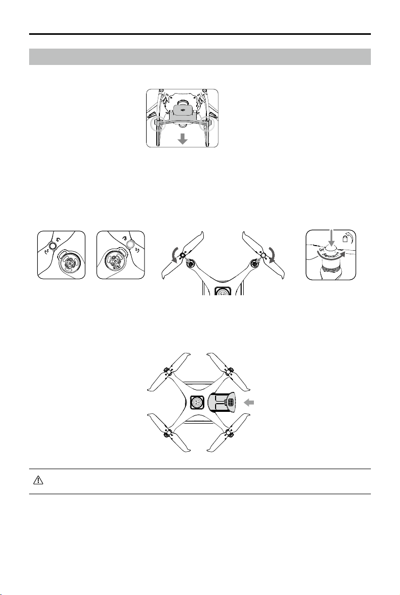
Preparing the Aircraft
1. Remove the gimbal clamp from the camera as shown in the gure.
2. Attaching the Propellers
Mount the propellers with black propeller rings to the motors with black dots. Mount the
propellers with sliver propeller rings to the motors without black dots. Press the propeller down
onto the mounting plate and rotate in the lock direction until it is secured.
3. Battery Installation
Slide battery into the battery compartment according to the arrow’s direction as shown below.
When the upper and lower buckles on the battery are in place, a click sound indicates the battery is
securely installed. Failure to do so may aect the ight safety of your aircraft.
2019 DJI All Rights Reserved.
©
7
Page 9
P4 Multispectral User Manual
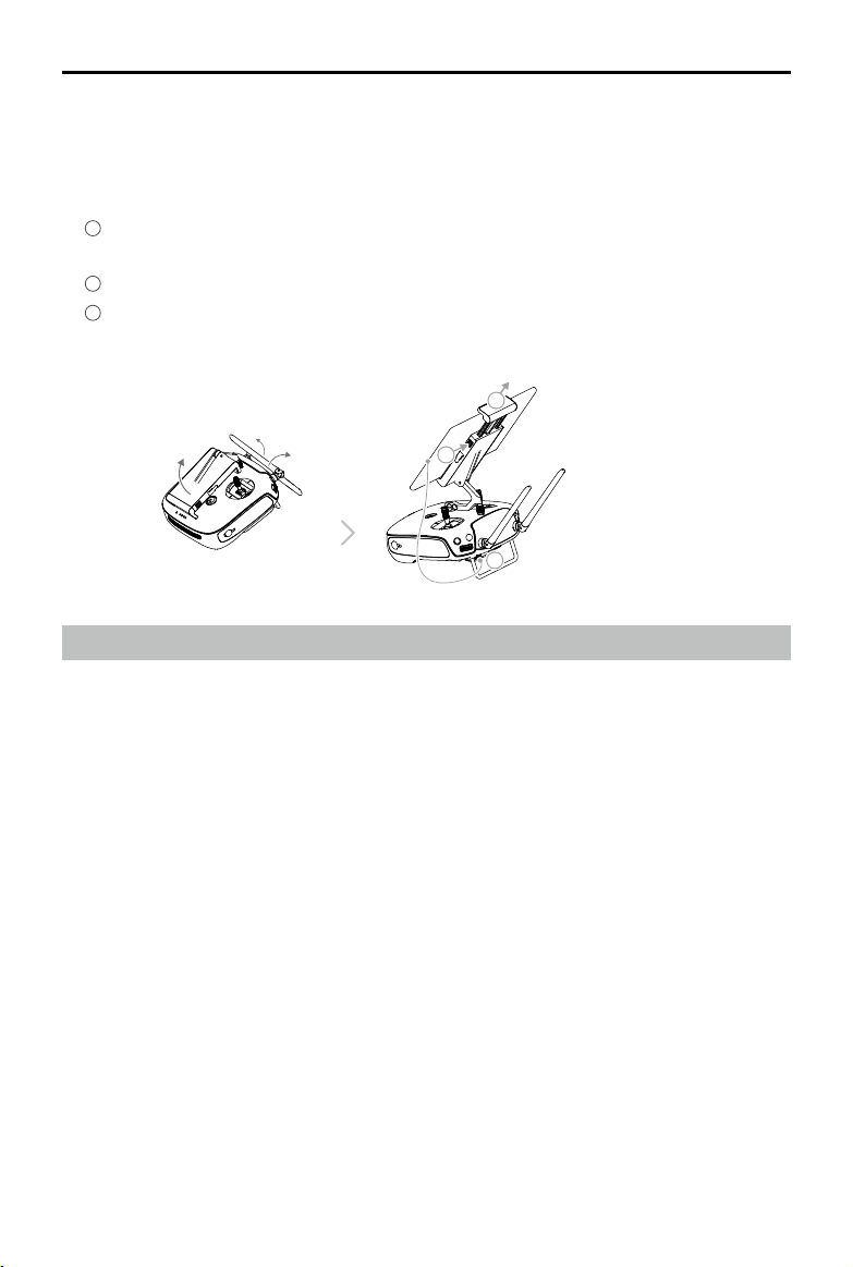
Preparing the Remote Controller
1. Tilt the mobile device holder or the display device on the remote controller to the desired
position, then adjust the antennas so they are facing outward.
2. Connecting your mobile device
1
Press the button on the top right side of the mobile device holder to release the clamp, then
adjust the clamp to t the size of your mobile device.
2
Secure your mobile device in the clamp by pressing down.
3
Plug one end of the cable into the mobile device, and the other end into the USB port on
the back of the remote controller.
2
1
3
Activating the Aircraft
When using your P4 Multispectral for the rst time, activate it using DJI GS Pro. Ensure that your
iPad has access to the internet.
2019 DJI All Rights Reserved.
8
©
Page 10
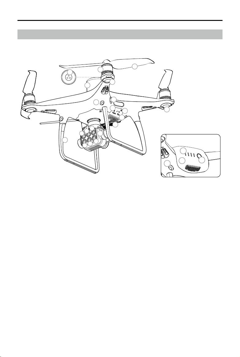
Aircraft Overview
P4 Multispectral User Manual
14
a
12
9
13
6
c
b
1
f
e
d
1. Gimbal Cameras
(with six cameras corresponding to the
wave bands below)
a. Red Edge (RE) b. Near-Infrared (NIR)
c. Green (G) d. Visible Light (RGB)
e. Red (R) f. Blue (B)
2. Downward Vision System
3. Micro USB Port
4. Camera/Linking Status Indicator and Link
Button
5. Camera microSD Card Slot
6. Forward Vision System
7. Infrared Sensing System
10
8
7
5
4
3
2
8. Front LEDs
9. Motors
10. Propellers
11. Aircraft Status Indicators
12. OcuSync Antennas
13. Onboard D-RTK Antenna
14. Spectral Sunlight Sensor
15. Rear Vision System
16. Intelligent Flight Battery
17. Power Button
18. Battery Level Indicators
11
18
16
15
17
2019 DJI All Rights Reserved.
©
9
Page 11
P4 Multispectral User Manual
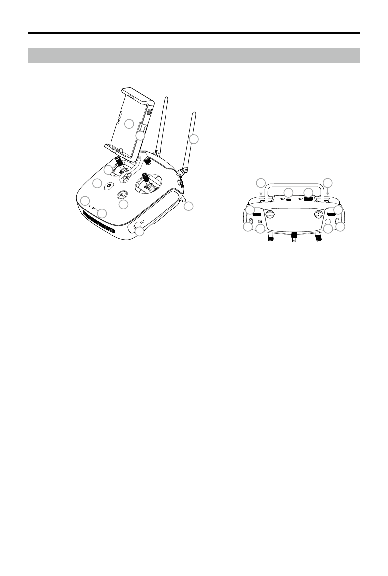
Remote Controller Overview
7
8
3
1
4
2
5
6
9
17
10
11
13
14
17
1819
12
16
15
1. Power Button
Used to turn the remote controller on and o.
2. Return to Home (RTH) Button
Press and hold this button to initiate RTH.
3. Control Sticks
Controls aircraft movement. Can be set to
Mode 1, Mode 2, or Mode 3.
4. Status LED
Indicates whether the remote controller is
linked to the aircraft.
5. Battery Level LEDs
Displays the battery level of the remote
controller.
6. Power Port
Connect to the charger to charge the
battery of the remote controller.
7. Mobile Device Holder
Securely mounts your mobile device to the
remote controller.
8. Small Device Positioning Tabs (for mobile
phones)
9. Antennas
Relays aircraft control and image
transmission signals.
10. Handle Bar
2019 DJI All Rights Reserved.
10
©
11. Gimbal Dial
Use this dial to control the tilt of the
gimbal.
12. Reserved Dial
13. Video Recording Button
Press to start recording video. Press again
to stop recording. (Video recording feature
available soon)
14. Flight Mode Switch
The P and S positions on the remote
controller are for P-mode, and the A
position is for A-mode.
15. Shutter Button
Press to take a photo. Two-stage button.
Pictures will only be taken when the
shutter button is fully pressed.
16. Reserved Blank Button
17. C1 and C2 Buttons (customizable, custom
functions available soon)
18. USB Port (for mobile device connection)
Connection to mobile device for DJI GS Pro.
19. Micro USB Port
Connects to a computer via a Micro USB
cable for conguration.
Page 12
Aircraft
This section introduces the aircraft
components, features and functions.
2019 DJI All Rights Reserved.
©
11
Page 13

Aircraft
Profile
The P4 Multispectral aircraft includes a ight controller, a communication system, a positioning
system, a propulsion system and an Intelligent Flight Battery. This section describes the functions
of these components.
Flight Modes
The P4 Multispectral provides the following flight modes. Use the flight mode switch on the
remote controller to switch between dierent ight modes. The P and S positions on the remote
controller are for P-mode, and the A position is for A-mode.
P-mode (Positioning): P-mode works best when the GNSS signal is strong. The aircraft utilizes
the GNSS / RTK module and Vision System to automatically stabilize itself and navigate between
obstacles. When the GNSS signal is strong, the aircraft uses GNSS for positioning. When RTK
module is enabled and the differential data transmission is good, it provides centimeter-level
positioning. When the GNSS signal is weak and the lighting conditions are sucient, the aircraft
uses Vision System for positioning. When the forward obstacle sensing is enabled and lighting
conditions are sucient, the maximum ight attitude angle is 25° with a maximum ight speed of
31 mph (50 kph). When forward obstacle sensing is disabled, the maximum ight attitude angle is
35° and the maximum ight speed is 36 mph (58 kph).
A-mode (Attitude): GNSS is not used for positioning and the aircraft can only maintain altitude
using the barometer.
Attitude Mode Warning
The aircraft will enter A-mode in the following two instances:
Passive: When there is weak GNSS signal or when the compass experiences interference where the Vision System is unavailable.
Active: Users toggle the flight mode switch to A-mode.
In A-mode, the Vision System and some advanced features are disabled. Therefore,
the aircraft cannot position or auto-brake in this mode and is easily affected by its
surroundings, which may result in horizontal shifting. Use the remote controller to
position the aircraft.
Maneuvering the aircraft in A-mode can be difficult. Before switching the aircraft into
A-mode, make sure you are comfortable flying in this mode. DO NOT fly the aircraft too
far away as you might lose control and cause a potential hazard. Avoid flying in confined
spaces or in areas where the GNSS signal is weak. Otherwise, the aircraft will enter A-mode,
leading to potential flight risks. Land the aircraft in a safe place as soon as possible.
2019 DJI All Rights Reserved.
12
©
Page 14
P4 Multispectral User Manual
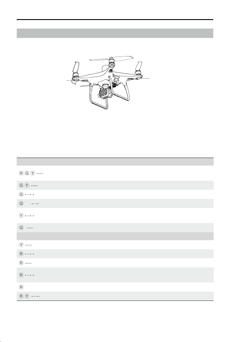
Aircraft Status Indicators
The P4 Multispectral has Front LEDs and Aircraft Status Indicators. The positions of these LEDs
are shown in the gure below:
Front LEDs
Aircraft Status Indicators
The Front LEDs show the orientation of the aircraft. The Front LEDs glow solid red when the aircraft is turned on to indicate the front (or nose) of the aircraft. The Aircraft Status Indicators communicate the system status of the ight controller. Refer to the table below for more information
about the Aircraft Status Indicators.
Aircraft Status Indicator Description
Normal
Alternate red, green and yellow ashing
Alternate green and yellow ashing Warming Up
Slow green ashing P-mode with GNSS or RTK
×2 Two green ashes P-mode with Vision System
Slow yellow ashing
Fast green ashing Braking
Warning
Fast yellow ashing Remote Controller Signal Lost
Slow red ashing Low Battery Warning
Fast red ashing Critical Battery Warning
Red ashing
— Solid red Critical Error
Alternate red and yellow ashing Compass Calibration Required
Turning On and Self Diagnostic
Testing
A-mode but No GNSS or Vision
System
Uneven Placement or Large Sensors
Bias
2019 DJI All Rights Reserved.
©
13
Page 15
P4 Multispectral User Manual
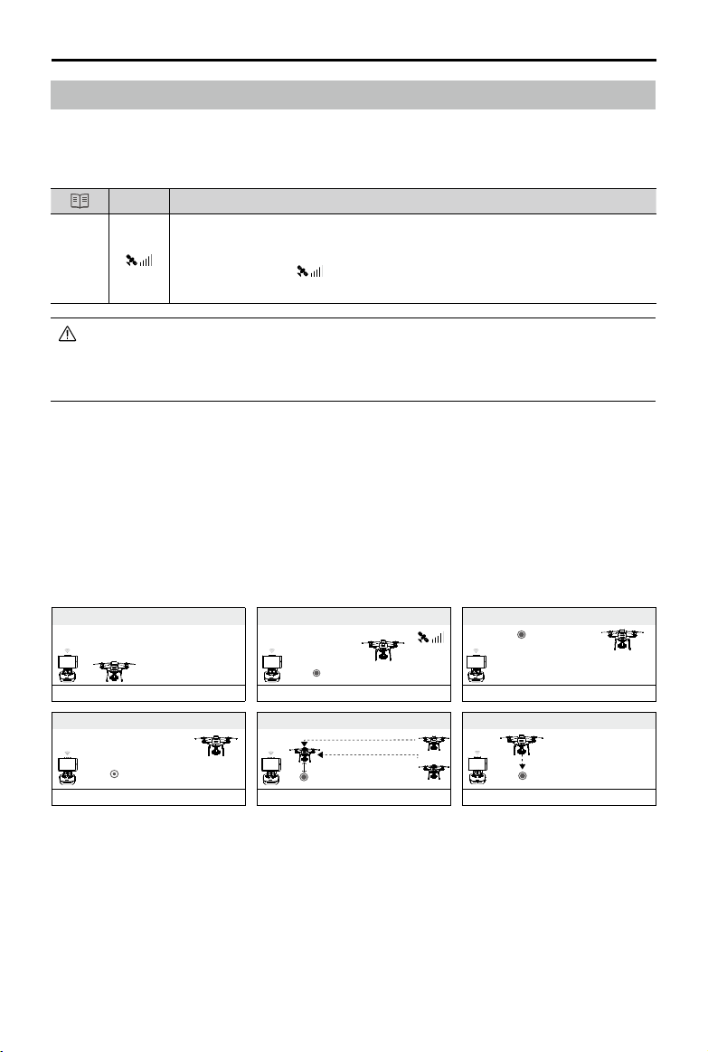
Return to Home (RTH)
Return to Home (RTH) function brings the aircraft back to the last recorded Home Point. There
are three types of RTH: Smart RTH, Low Battery RTH, and Failsafe RTH. This section describes
these three scenarios in detail.
GNSS
Description
If a strong GNSS signal was acquired before takeoff, the Home Point is the
Home
Point
location from which the aircraft launched. The GNSS signal strength is indicated
by the GNSS icon ( Less than 4 bars is considered a weak GNSS signal).
The aircraft status indicators will blink rapidly when the home point is recorded.
The aircraft can sense and avoid obstacles when the Forward Vision System is enabled and lighting
conditions are sucient. The aircraft will automatically climb up to avoid obstacles and descend slowly
as it returns to the Home Point. To ensure the aircraft returns home forwards, it cannot rotate or y left
and right during RTH while the Forward Vision System is enabled.
Failsafe RTH
The Forward Vision System allows the aircraft to create a real-time map of its ight route as it ies.
If the Home Point was successfully recorded and the compass is functioning normally, Failsafe
RTH will be automatically activated if the remote controller signal is lost for more than three
seconds. The aircraft will plan its return route and retrace its original ight route home. During
RTH, if the remote controller signal is recovered, users can control the aircraft altitude and speed.
Press the RTH button once to cancel RTH.
Failsafe Illustration
1 Record Home Point
Blinking Green
4
Signal Lost Lasts (after 3 sec.)
>3S
× ×
Fast Blinking Yellow
2 Conrming Home Point
Blinking Green
5
RTH (adjustable altitude)
Height over HP>Failsafe Altitude
Elevate to Failsafe Altitude
Failsafe Altitude
Fast Blinking Yellow
Height over HP<=Failsafe Altitude
3 Remote Controller Signal Lost
×
Fast Blinking Yellow
6 Landing (after hovering for 5 secs)
×
Fast Blinking Yellow
Smart RTH
Use the RTH button on the remote controller when GNSS is available to initiate Smart RTH. The
aircraft will then automatically return to the last recorded Home Point. Use the remote controller
to control the aircraft’s speed or altitude to avoid a collision during the Smart RTH process. As
the aircraft returns, it will use the primary camera to identify obstacles as far as 300m in front,
allowing it to plan a safe route home. Press and hold the Smart RTH button once to start the
process, and press the Smart RTH button again to terminate the procedure and regain full
control of the aircraft.
2019 DJI All Rights Reserved.
14
©
Page 16
P4 Multispectral User Manual
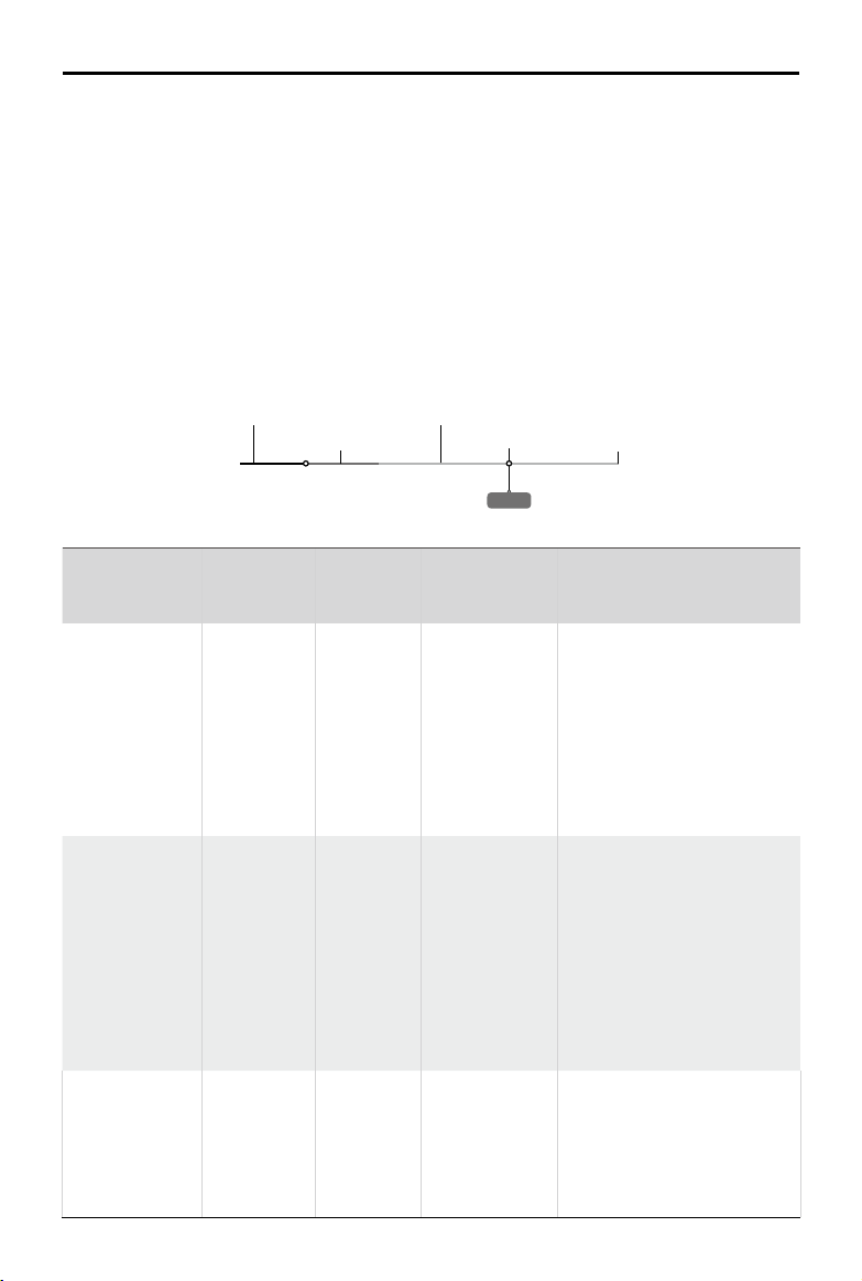
Low Battery RTH
The low battery level failsafe is triggered when the DJI Intelligent Flight Battery is depleted to
a point that may aect the safe return of the aircraft. The user can cancel the RTH procedure
by pressing the RTH button on the remote controller. The thresholds for these warnings are
automatically determined based on the aircraft’s current altitude and distance from the Home
Point. The Low Battery RTH will only be triggered once during the same ight.
The aircraft will land automatically if the current battery level can only support the aircraft long
enough to descend from its current altitude. The user cannot cancel the auto landing but can use
the remote controller to alter the aircraft’s orientation during the landing process.
The Battery Level Indicator is displayed in DJI GS Pro, and is described below:
Critical Low battery level warning
(Red)
Low battery
level warning (Yellow)
Sucient battery
level (Green)
Remaining ight time
Battery Level
Warning
Low battery
level warning
Critical Low
battery level
warning
Estimated
remaining ight
time
Power requires to return home
Remark
Battery
power is
low. Fly
the aircraft
back.
The aircraft
must land
immediately.
Estimated
remaining
flight based
on current
battery
level.
12:29
Battery level Indicator
Aircraft
Status
DJI GS Pro Flight Instructions
Indicator
The aircraft will return to the
Home Point automatically and
Aircraft
status
indicator
blinks RED
slowly.
N/A
hover at 2 meters above the
Home Point. Users can also
cancel the RTH process and
land manually. Note: The Low
Battery Level Warning will not
prompt after users cancel
RTH and regain control.
DJI GS Pro
display will
ash red and
Aircraft
status
indicator
blinks RED
quickly.
the aircraft
will start to
descend.
The remote
controller will
sound an
Allow the aircraft to descend
and land automatically.
alarm.
N/A N/A N/A
2019 DJI All Rights Reserved.
©
15
Page 17
P4 Multispectral User Manual
5m
H
When the Critical low battery level warning is triggered and the aircraft begins to land automatically,
push the left stick upward to make the aircraft hover at its current altitude, giving you an opportunity
to navigate to a more appropriate landing location.
The colored zones and markers on the battery level indicator bar reect the estimated remaining
ight time. They are automatically adjusted according to the aircraft’s current location and status.
The Low Battery Warning threshold set in the Aircraft Battery settings page in the app is only for an
alert and will not trigger RTH.
Precision Landing
The aircraft automatically scans and attempts to match the terrain features underneath during
Return to Home. When current terrain matches home point terrain, the aircraft will start landing
immediately to achieve precision landing.
Landing Protection is active during precision landing.
Precision Landing performance is subject to the following conditions:
a) Home point is recorded upon take o, and cannot not be refreshed during ight.
b) Aircraft must take o vertically. Take o altitude must be greater than 7 meters.
c) Home point terrain features remain largely unchanged.
d) Home point terrain with no distinctive features will aect the performance.
e) Lighting conditions cannot be too light nor too dark.
The following actions are available during landing:
a) Pull throttle down to accelerate landing.
b) Moving the control sticks in any other direction will stop Precision Landing. The aircraft will descend
vertically and Landing Protection will remain active.
RTH Safety Notices
20m
5m
H
2019 DJI All Rights Reserved.
16
©
The aircraft cannot avoid obstruction during RTH when the Forward
Vision System is disabled. Users can use the remote controller to
control aircraft altitude and speed. It is important to set a suitable
Failsafe altitude before each flight. Go to Camera View in DJI
GS Pro, tap the text under the Smart RTH button to set an RTH
altitude.
If the aircraft is ying under 65 feet (20 meters) and RTH (including
Smart RTH, Low Battery RTH and Failsafe RTH) is triggered, the
aircraft will rst automatically ascend to 65 feet (20 meters) from the
current altitude. You can only cancel the ascending by exiting the RTH.
The aircraft will automatically descend and land if RTH is triggered
when the aircraft ies within a 16-feet (5 meters) radius of the Home
Point and when the aircraft altitude is under 98 feet (30 meters), or
if the obstacle sensing function is disabled. The aircraft will not as-
cend, and will land immediately at the current location.
Page 18

P4 Multispectral User Manual
Aircraft cannot return to the Home Point when GNSS signal is weak
( [ ] displays grey) or the module is unavailable.
If you move the throttle stick after the aircraft rises above 65 feet (20
meters) but below the pre-set Failsafe RTH altitude, the aircraft will
stop ascending and immediately return to the Home Point.
Obstacle Avoidance During RTH
Aircraft can now sense and actively attempt to avoid obstacles during RTH, provided that the
lighting conditions are adequate for the Forward Vision System. Upon detecting an obstacle, the
aircraft will act as follows:
1. The aircraft will use the primary camera to identify obstacles as far as 984 feet (300 meters) in
front, allowing it to plan a safe route home.
2. The aircraft decelerates when an obstacle is sensed at 49 feet (15 meters) ahead.
3. The aircraft stops and hovers then starts ascending vertically to avoid the obstacle. Eventually,
the aircraft will stop climbing when it is at least 16 feet (5 meters) above the detected obstacle.
4. Failsafe RTH procedure resumes, the aircraft will continue flying to the Home Point at the
current altitude.
300 meters
The Obstacle Sensing function is disabled during RTH descent. Operate with care.
To ensure the aircraft returns home forwards, it cannot rotate during RTH while the Forward Vision
System is enabled.
The aircraft cannot avoid obstacles above, beside, or behind the aircraft.
5 meters
15 meters
Landing Protection Function
Landing Protection will activate during auto landing.
1. Landing Protection determines whether the ground is suitable for landing. If so, the aircraft will
land gently.
2. If Landing Protection determines that the ground is not suitable for landing, the aircraft will
hover and wait for pilot confirmation. The aircraft will hover if it detects the ground is not
appropriate for landing even with a critically low battery warning. Only when the battery level
2019 DJI All Rights Reserved.
©
17
Page 19

P4 Multispectral User Manual
decreases to 0% will the aircraft land. Users retain control of aircraft ight orientation.
3. If Landing Protection is inactive, DJI GS Pro will display a landing prompt when the aircraft
descends below 0.3 meters. Tap to conrm or pull down the control stick for 2 seconds to
land when the environment is appropriate for landing.
Landing Protection will not be active in the following circumstances:
•
a) When the user is controlling the pitch/roll/throttle sticks (Landing ground detection will re-activate
when control sticks are not in use)
b) When the positioning system is not fully functional (e.g. drift position error)
c) When the Downward Vision System needs re-calibration
d) When light conditions are not sucient for the Downward Vision System
• If an obstacle is within 1-meter of the aircraft, the aircraft will descend to 0.3m above the ground
and hover. The aircraft will land upon with user conrmation.
Aerial Photography Missions
Create automated ight missions in DJI GS Pro by planning ight paths and setting parameters.
Refer to the DJI GS Pro User Manual for details on flight planning and mission execution.
The following section will guide you on how to set the parameters for both RGB imaging and
multispectral imaging, as well as the storage of the photos.
Camera Settings
Go to Camera View in the app, and tap to enter camera settings.
In , congure RGB imaging settings and multispectral imaging settings.
RGB imaging settings:
Camera View will display an RGB image during conguration.
1. Select between Auto and Manual mode. Users can adjust ISO and shutter values when
Manual mode is selected.
2. Set the exposure value (EV).
Multispectral imaging settings:
Camera View will display a multispectral image showing NDVI in real time during conguration.
In the parameters list, the wavelength for each imaging band and its corresponding gain will be
displayed.
1. Select between Auto and Manual mode. Users can adjust the shutter value when Manual
mode is selected.
2. Set EV.
When multispectral camera is selected in Camera View for a mission, this mission will not capture
•
RGB photos, which are required for 2D multispectral map reconstruction in DJI Terra. It is
recommended to select visible camera in Camera View before starting the mission to ensure RGB
images are collected for reconstruction in DJI Terra.
When conguring parameters for a mission, it is recommended to set the Shooting Angle to Course
•
Aligned to ensure mapping accuracy.
2019 DJI All Rights Reserved.
18
©
Page 20

P4 Multispectral User Manual
In , set the capture mode, bands to be stored, and NDVI colormap.
Capture mode: Select between single shot and timed shot.
Bands to be stored:
Choose which spectral band photos to save according to the application.
When conguring visible imaging settings, users can select RGB, BLUE, GREEN, RED, RE, and NIR.
When conguring multispectral imaging settings, users can select NDVI, BLUE, GREEN, RED,
RE, and NIR.
Only the photos of the selected bands will be saved. At least one band should be selected.
NDVI colormap:
Set the rendered display color scale in the live view according to the numerical value of the
vegetation index. (available soon)
Photos Storage
Depending on the bands selected, up to 6 photos will be taken and saved every time. The photo
for each band in the group has its own le name. The naming rule is “DJI_XXXY”. XXX refers to
the number of the photo group. Y, with a value of 0 to 5, corresponds to dierent imaging bands:
Y 0 1 2 3 4 5
Imaging Band RGB or NDVI BLUE GREEN RED RE NIR
Generating Multispectral Maps
Import the image data into DJI GS Pro or DJI Terra to generate multispectral maps. Refer to their
user manuals for details.
RTK Functions
The P4 Multispectral has a built-in DJI Onboard D-RTK, which provides more accurate data for
centimeter-level positioning to improve operation precision when using with the DJI D-RTK 2 High
Precision GNSS Mobile Station or Network RTK service. The onboard D-RTK, providing precision
position and speed information combined with optimized algorithms, is more accurate than a
standard compass sensor and functions even with magnetic interference from metal structures,
ensuring stable ight. If the RTK signal is weak and dierential data cannot be transmitted during
a mission, users can read the raw satellite observations* recorded in the microSD card in the
aircraft after the ight, and then use PPK technology to achieve centimeter-level positioning.
* Supported later.
2019 DJI All Rights Reserved.
©
19
Page 21

P4 Multispectral User Manual
Using with the DJI D-RTK 2 Mobile Station
1. Go to Mission Page in DJI GS Pro, tap the icon or RTK on top of the screen to go
to the RTK settings menu, and then select D-RTK 2 as the RTK data source. Enable the
aircraft RTK at the bottom of the menu to ensure the aircraft has access to RTK data.
2. Tap Link. The remote controller will start beeping. Then press the link button on the mobile station.
3. Tap Connect to establish connection with the server. Wait for the RTK icon to display FIX, indicating
that the dierential data calculation is completed and the aircraft can use RTK for positioning.
Using with Network RTK Service
The Network RTK service uses the remote controller instead of the base station to connect to an
approved Network RTK server to send and receive dierential data. Keep the remote controller
on and the mobile device connected to the internet when using this function.
1. Ensure that the remote controller is connected to the aircraft and the mobile device has
access to the Internet.
2. Go to Mission Page in DJI GS Pro, tap the icon or RTK on top of the screen to go to the
RTK settings menu, and then select Network RTK Account as the RTK data source.
3. Tap New in the Network RTK Account setting page. After configuration, go back to the
settings menu to select the added account.
4. Enable the aircraft RTK at the bottom of the menu to ensure the aircraft has access to RTK data.
5. Tap Connect to establish connection with the server. Wait for the RTK icon to display FIX,
indicating that the differential data calculation is completed and the aircraft can use RTK for
positioning.
Vision System and Infrared Sensing System
The main components of the Vision System are located on the front, rear and bottom of the
aircraft, including [1] [2] [4] three stereo vision sensors and [3] two ultrasonic sensors. The Vision
System uses ultrasound and image data to help the aircraft maintain its current position, enabling
precision hovering indoors or in environments where a GNSS signal is not available. The Vision
System constantly scans for obstacles, allowing the aircraft to avoid them by going over, around,
or hovering.
The Infrared Sensing System consists [5] of two 3D infrared modules on both sides of the aircraft.
These scan for obstacles on both sides of the aircraft and is active in certain ight modes.
[5]
[1]
[2]
[3]
2019 DJI All Rights Reserved.
20
©
[4]
Page 22

P4 Multispectral User Manual
Detection Range
The detection range of the Vision System and Infrared Sensing System are depicted as follow. Note
that the aircraft cannot sense and avoid the obstacles that are not within the detection range.
0.7m
13.1cm
6.8m
7m
0.7m
In P-mode, both the forward and the rear Vision Systems work if the speed is within 13mph (22kph).
At higher speeds, only the vision system facing the direction of travel is active.
6.8m
7m
Calibrating Sensors
Vision Systems cameras installed on the aircraft are calibrated on delivery. However these
cameras are vulnerable to excessive impact and will require occasional calibration via DJI
Assistant 2 for Phantom. Follow the steps below to calibrate the sensors.
01
02
Align the boxes
03
Pan and tilt the aircraft
Using Vision Positioning
Vision Positioning is activated automatically when the aircraft is turned on. No further action is
required. Vision Positioning is typically used in indoor environments, where GNSS is unavailable.
Using the sensors that are built into the Vision System, the aircraft can hover precisely even
without GNSS. The Downward Vision System works best when the aircraft is at altitudes of under
33 ft (10 m). Operate the aircraft with great caution when ying at high speeds at low altitudes
(under 0.5 m).
2019 DJI All Rights Reserved.
©
21
Page 23

P4 Multispectral User Manual
Follow the steps below to use Vision Positioning:
1. Turn on the aircraft. The aircraft status indicator will ash green two times, which indicates the
Vision Positioning is ready.
2. Gently push the left stick up to lift o and the aircraft will hover in place.
Assisted Braking from Obstacle Sensing
Powered by the Obstacle Sensing, the aircraft will now be able to actively brake when obstacles
are detected around the aircraft. Note that Obstacle Sensing function works best when lighting
is adequate and the obstacle is clearly marked or textured. The aircraft must y at no more than
31mph (50kph) to allow sucient braking distance.
The 3D Infrared Sensing System is only active in Beginner mode* and Tripod mode*. Fly with caution.
The performance of your Vision System and Infrared Sensing System are aected by the surface
being own over. Ultrasonic sensors may not be able to accurately measure distances when
operating above sound-absorbing materials and the camera may not function correctly in suboptimal
environments. The aircraft will switch from P-mode to A-mode automatically if neither vision sensors
nor ultrasonic sensors and Infrared Sensing System are available. Operate the aircraft with great
caution in the following situations:
a) Flying over monochrome surfaces (e.g. pure black, pure white, pure red, pure green).
b) Flying over a highly reective surfaces.
c) Flying at high speeds of over 31mph (50kph) at 2 meters or over 11mph (18kph) at 1 meter.
d) Flying over water or transparent surfaces.
e) Flying over moving surfaces or objects.
f) Flying in an area where the lighting changes frequently or drastically.
g) Flying over extremely dark (lux < 10) or bright (lux > 100,000) surfaces.
h) Flying over surfaces that can absorb sound waves (e.g. thick carpet).
i) Flying over surfaces without clear patterns or texture.
j) Flying over surfaces with identical repeating patterns or textures (e.g. tiling).
k) Flying over inclined surfaces that will deect sound waves away from the aircraft.
l) Flying over obstacles with too small eective infrared reective surface.
m) DO NOT position the sides of two aircraft toward each other to avoid interference between the
3D infrared modules.
n) DO NOT cover the protective glass of the infrared module. Keep it clean and undamaged.
o) Flying at high speed at low altitude (under 0.5 m).
Keep sensors clean at all times. Dirt or other debris may adversely aect their eectiveness.
Vision Positioning is only eective when the aircraft is at altitudes of 0.3 to 10 meters.
The Vision Positioning may not function properly when the aircraft is ying over water.
The Vision System may not be able to recognize pattern on the ground in low light conditions (less
than 100 lux).
Do not use other ultrasonic devices with frequency of 40 kHz when Vision System is in operation.
* This mode will be supported later.
2019 DJI All Rights Reserved.
22
©
Page 24

P4 Multispectral User Manual
Flight Recorder
Flight data is automatically recorded to the internal storage of the aircraft. To access this data,
connect the aircraft to the PC through the Micro USB port and launch the DJI Assistant 2.
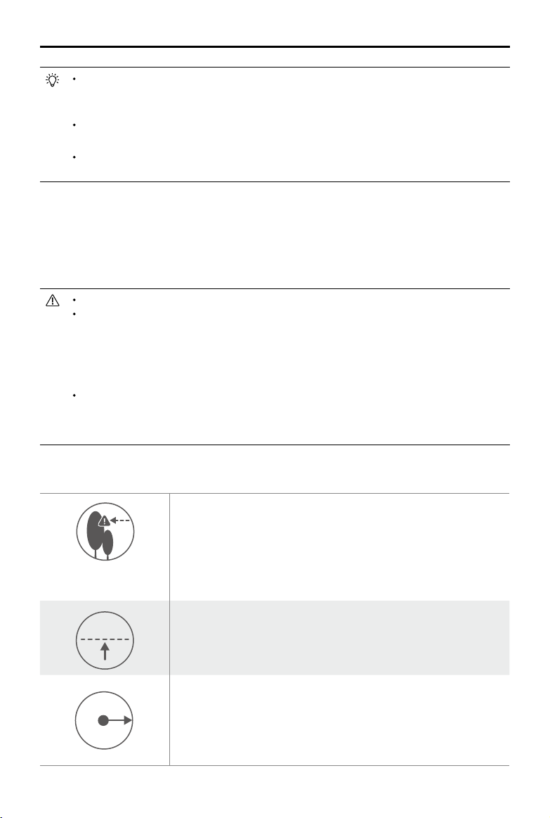
Attaching and Detaching the Propellers
Use only DJI approved propellers with your aircraft. The grey and black ring on the propeller indi-
cate where they should be attached and in which direction whey should spin.
Propellers Silver Ring Black Ring
Figure
Attach On Motors without black dots Motors with black dots
Lock : Turn the propellers in the indicated direction to mount and tighten.
Legends
Attaching the Propellers
1. Be sure to remove the warning stickers from the motors before attaching the propellers.
2. Mount the propellers with black propeller rings to the motors with black dots. Mount the
propellers with sliver propeller rings to the motors without black dots. Press the propeller down
onto the mounting plate and rotate in the lock direction until it is secured in its position.
Unlock : Turn the propellers in the indicated direction to loosen and
remove.
Detaching the Propellers
Press the propellers down into the motor mount and rotate in the unlock direction.
Be aware of the sharp edges of the propellers. Handle with care.
Use only the DJI approved propellers. Do not mix propeller types.
Check that the propellers and motors are installed correctly and rmly before every ight.
Ensure that all propellers are in good condition before each ight. DO NOT use aged, chipped, or
broken propellers.
To avoid injury, STAND CLEAR of and DO NOT touch propellers or motors when they are spinning.
ONLY use original DJI propellers for a better and safer ight experience.
2019 DJI All Rights Reserved.
©
23
Page 25

P4 Multispectral User Manual
DJI Intelligent Flight Battery
The DJI Intelligent Flight Battery has a capacity of 5870 mAh, a voltage of 15.2 V, and a smart
charge/discharge functionality. It should only be charged using an appropriate DJI approved
power adapter and charging hub.
Intelligent Flight Battery AC Power Adapter Charging Hub
The Intelligent Flight Battery must be fully charged before using it for the rst time.
Never insert or remove the battery when it is turned on.
Ensure the battery is mounted rmly. The aircraft will not take o if the battery is mounted incorrectly.
DJI Intelligent Flight Battery Functions
1. Battery Level Display: The LED indicators display the current battery level.
2. Auto-Discharging Function: To prevent swelling, the battery automatically discharges to
below 65% of total power when it is idle for more than ten days. It takes around two days to
discharge the battery to 65%. It is normal to feel moderate heat being emitted from the battery
during the discharge process.
3. Balanced Charging: Automatically balances the voltage of each battery cell when charging.
4. Overcharge Protection: Charging automatically stops when the battery is fully charged.
5. Temperature Detection: The battery will only charge when the temperature is between 5°C
(41°F) and 40°C (104°F).
6. Over Current Protection: The battery stops charging when a high amperage (more than 8 A) is
detected.
7. Over Discharge Protection: To prevent over-discharge damage, discharging automatically
stops when the battery voltage reaches 12 V.
8. Short Circuit Protection: Automatically cuts the power supply when a short circuit is detected.
9. Battery Cell Damage Protection: DJI GS Pro displays a warning message when a damaged
battery cell is detected.
10. Sleep Mode: To save power, the battery enter sleep mode after 20 minutes of inactivity.
11. Communication: Information pertaining to the battery’s voltage, capacity, current, etc. is
transmitted to the aircraft’s main controller.
Refer to Phantom 4 Series Intelligent Flight Battery Safety Guidelines before use. Users
take full responsibility for all operations and usage.
2019 DJI All Rights Reserved.
24
©
Page 26

P4 Multispectral User Manual
Using the Battery
LED1
LED2
LED3
LED4
Power Button (Built-in LED)
Battery Level Indicators
Turning ON/OFF
Turning On: Press the Power Button once, then press again and hold for 2 seconds to turn on.
The Power LED will turn green and the Battery Level Indicators will display the current
battery level.
Turning
Press the Power Button once, then press again and hold for 2 seconds to turn o. The
Off:
battery power LED will flash when powering off the Phantom to allow automatically
stopping of a recording during the event recording wasn’t stopped.
Low Temperature Notice:
1. Battery capacity is signicantly reduced when ying in low temperature (< 0°C) environments.
2. It is not recommended that the battery be used in extremely low temperature (< -10°C)
environments. Battery voltage should reach the appropriate level when operating environment
with temperatures between -10°C and 5°C.
3. End the flight as soon as DJI GS Pro displays the “Low Battery Level Warning” in low
temperature environments.
4. Keep the battery indoors to warm it before ying in low temperature environments.
5. To ensure optimal performance of the battery, keep the battery temperature above 20°C.
6. The charger will stop charging the battery if the battery cell’s temperature is not within the
operating range (0°C ~ 40°C ).
In cold environments, insert the battery into the battery compartment and turn on the aircraft for
approximately 1-2 minutes to warm up before taking o.
2019 DJI All Rights Reserved.
©
25
Page 27

P4 Multispectral User Manual
Checking the Battery Level
The Battery Level Indicators display how much power remains. When the battery is turned o,
press the Power Button once. The Battery Level Indicators will light up to display the current
battery level. See below for details.
The Battery Level Indicators will also show the current battery level during charging and discharging.
The indicators are dened below.
: LED is on. : LED is ashing.
: LED is o.
Battery Level Indicators
LED1 LED2 LED3 LED4 Battery Level
87.5%~100%
75%~87.5%
62.5%~75%
50%~62.5%
37.5%~50%
25%~37.5%
12.5%~25%
0%~12.5%
=0%
Charging the Intelligent Flight Battery
Air cool the Intelligent Flight Battery after each ight. Allow its temperature to drop to room
temperature before charging.
The charging temperature range is 5° to 40° C. The battery management system will stop the battery
from charging when the battery cell temperature is out of range.
Always turn o the battery before inserting it or removing it from the aircraft. Never insert or remove a
battery when it is turned on.
Using only the Power Adapter for Charging
1. Connect the AC power adapter to a power source (100-240 V 50/60 Hz).
2. Connect the Intelligent Flight Battery to the power adapter to start charging. If the battery level
is above 95%, turn on the battery before charging.
3. The Battery Level Indicator will display the current battery level as it is charging.
4. The Intelligent Flight Battery is fully charged when the Battery Level Indicators are all o.
Power Outlet
2019 DJI All Rights Reserved.
26
©
AC Power Adapter
Intelligent Flight Battery
Page 28

P4 Multispectral User Manual
Battery Level Indicators While Charging
LED1 LED2 LED3 LED4 Battery Level
0%~25%
25%~50%
50%~75%
75%~100%
Fully Charged
Using the Power Adapter and Charging Hub for Charging
1. Connecting to a Power Source
Connect the power adapter to a power outlet (100-240V, 50/60Hz), then connect the charging
bub to the power adapter.
Charging Hub
AC Power Adapter
Power Outle
2. Connecting Batteries
Charging Mode:
Align the grooves on the Intelligent Flight Battery with the battery slot tracks to insert the
battery and begin charging. The Intelligent Flight Battery with the highest power level will be
charged rst. Other batteries will be charged in sequence according to their power levels.
If the Status LED Indicator of the charging hub is solid green and the LED lights on the
Intelligent Flight Battery turn o, charging is complete and the Intelligent Flight Battery can be
disconnected from the charging hub.
Storage Mode:
The charging hub will discharge batteries with more than 50% power to reduce the charge to
50%. Meanwhile batteries with less than 50% charge will be charged to 50%.
Battery
Slot Track
2019 DJI All Rights Reserved.
©
27
Page 29

P4 Multispectral User Manual
Be sure to align the grooves on the Intelligent Flight Battery with the battery slot tracks. The Status
LED Indicator will turn solid yellow if the battery is properly inserted.
In storage mode, you can power on the Intelligent Flight Batteries to discharge them without having to
connect to a power source if all batteries have more than 50% power.
Status LED Indicator Description
Status LED Indicator Description
Charging Mode
—
Solid Yellow
......
Blinking Green
—
Solid Green
—
Solid Red
......
All Blinking Red
Storage Mode
—
Solid Yellow
......
Blinking Blue
—
Solid Blue
—
Solid Red
......
All Blinking Red
Queuing to charge
Charging
Fully charged
No battery detected
Power supply error, please check the connection to the Battery Charger
Ready to charge or discharge
Charging or discharging
The battery’s power level is 50%
No battery detected
Power supply error, please check the connection to the Battery Charger
Battery Protection LED Display
The table below shows battery protection mechanisms and corresponding LED patterns.
Battery Level Indicators while Charging
LED1 LED2 LED3 LED4 Blinking Pattern Battery Protection Item
LED2 blinks twice per second Over current detected
LED2 blinks three times per
second
Short circuit detected
LED3 blinks twice per second Over charge detected
LED3 blinks three times per
second
LED4 blinks twice per second
LED4 blinks three times per
second
Over-voltage charger detected
Charging temperature is too
low
Charging temperature is too
high
After these issues are resolved, press the Power Button to turn o the Battery Level Indicator.
Unplug the Intelligent Flight Battery from the charger and plug it back in to resume charging. Note
that you do not need to unplug and plug in the charger in the event of a room temperature error;
the charger will resume charging when the temperature is within the allowable range.
2019 DJI All Rights Reserved.
28
©
Page 30

P4 Multispectral User Manual
DJI does not take any responsibility for damage caused by third-party chargers.
If the battery level is above 95%, turn on the battery before charging.
How to discharge your Intelligent Flight Battery:
Place the Intelligent Flight Battery into the battery compartment and turn it on. Fly the aircraft out
doors until the battery level is low (such as 20% of power left).
2019 DJI All Rights Reserved.
©
29
Page 31

Gimbal Cameras
This section provides the technical
specications of the cameras and
explains the gimbal operation.
2019 DJI All Rights Reserved.
30
©
Page 32

Gimbal Cameras
Cameras
Prole
The P4 Multispectral imaging system contains six cameras with 1/2.9-inch CMOS sensors,
including an RGB camera that produces images in the JPEG format and a multispectral camera
array containing five cameras that produce multispectral images in the TIFF format. It uses a
global shutter to ensure performance.
The ve cameras in the multispectral camera array can capture photos in the following imaging bands:
Blue (B): 450 nm ± 16 nm; Green (G): 560 nm ± 16 nm; Red (R): 650 nm ± 16 nm; Red edge (RE):
730 nm ± 16 nm; Near-infrared (NIR): 840 nm ± 26 nm.
Camera microSD Card Slot
The P4 Multispectral supports microSD cards up to 128 GB. A Class 10 or UHS-I and above
microSD card is recommended due to their fast read and write speeds. Users can read the
photos and videos, and the raw satellite observations recorded during missions from the
microSD card.
Do not remove the microSD card from the aircraft when it is shooting.
To ensure the stability of the camera system, single video recordings are capped at 30
minutes.
Micro USB Port
Turn on the aircraft and connect a Micro USB cable to the Micro USB Port to update rmware,
read the photos and videos, and the raw satellite observations recorded during missions.
2019 DJI All Rights Reserved.
©
31
Page 33

P4 Multispectral User Manual
Camera Operation
Use the shutter and video recording buttons on the remote controller or in DJI GS Pro to shoot
the photos or videos.
Gimbal
Prole
The 3-axis gimbal provides a steady platform for the attached camera, allowing you to capture
clear, stable images and video. Turn the dial to adjust the gimbal pitch angle.
The controllable range of the pitch angle is -90° to +30°. The range is -90° to 0° when conguring
parameters for a mission in DJI GS Pro, but the gimbal can be controlled manually to +30° using
the gimbal dial.
+30°
0°
-90°
A gimbal motor error may occur in these situations:
(1) the aircraft is placed on uneven ground or the gimbal’s motion is obstructed.
(2) the gimbal has been subjected to an excessive external force, such as a collision. Please take o
from at, open ground and protect the gimbal at all times.
Flying in heavy fog or clouds may make the gimbal wet, leading to temporary failure. The gimbal will
recover full functionality after it dries.
It is normal for the gimbal to produce a short beeping tone upon initialization.
2019 DJI All Rights Reserved.
32
©
Page 34

Remote Controller
This section describes the features
of the remote controller and includes
instructions for controlling the aircraft
and cameras.
2019 DJI All Rights Reserved.
©
33
Page 35

Remote Controller
Profile
The remote controller features DJI’s long-range transmission technology OcuSync that is
capable of controlling the aircraft and the gimbal cameras at a maximum transmission range of
4.3 mi (7 km). Connect an iPad to the remote controller via the USB port to use DJI GS Pro app
to plan and perform missions. Export the captured images for analysis and create multispectral
maps.
Compliance Version: The remote controller is compliant with local compliance and regulations.
Operating Mode: Control can be set to Mode 1 or Mode 2, or to a custom mode.
Mode 1: The right stick serves as the throttle.
Mode 2: The left stick serves as the throttle.
To prevent transmission interference, do not operate more than three aircrafts in the same area.
Using the Remote Controller
Turning the Remote Controller On and O
The P4 Multispectral remote controller is powered by a 2S rechargeable battery that has a capacity
of 6000 mAh. The battery level is indicated via the Battery Level LEDs on the front panel. Follow
the steps below to turn on your remote controller:
1. When the remote controller is turned off, press the Power Button once. The Battery Level
LEDs will display the current battery level.
2. Press and hold the Power Button to turn on the remote controller.
3. The remote controller will beep when it is turned on. The Status LED will rapidly blink green,
indicating that the remote controller is linking to the aircraft. The Status LEDs will glow solid
green when linking is complete.
4. Repeat Step 2 to turn o the remote controller.
2019 DJI All Rights Reserved.
34
©
Page 36

P4 Multispectral User Manual
Charging the Remote Controller
Charge the remote controller using the included charger. Refer to the figure below for more
details.
Power Outlet
Charger
Controlling the Camera
Shoot videos/photos, and adjust gimbal pitch angle via the Shutter Button, Video Recording
Button, and Gimbal Dial on the remote controller.
1
2
3
1. Gimbal Dial
Control the tilt of the gimbal. Turn left to tilt the gimbal upward and right to tilt the gimbal
downward.
2. Video Recording Button
Press once to start recording video, then press again to stop recording.
3. Shutter Button
Press to take a photo. Two-stage button. Pictures will only be taken when the shutter button is
fully pressed.
2019 DJI All Rights Reserved.
©
35
Page 37

P4 Multispectral User Manual
Controlling the Aircraft
This section explains how to control the orientation of the aircraft through the remote controller.
Control can be set to Mode 1 , Mode 2 or Mode 3, or to a custom mode.
Mode 1
Left Stick
Forward
Right Stick
Up
Mode 2
Mode 3
Backward
Turn RightTurn Left
Right StickLeft Stick
Up
Down
Turn RightTurn Left
Left Stick Right Stick
Forward
Backward
Down
RightLeft
Forward
Backward
RightLeft
Up
Down
RightLeft
The remote controller is set to Mode 2 by default.
Stick Neutral/Mid-Point: Control sticks are in the center position.
Moving the Control Stick: The control stick is pushed away from the center position.
2019 DJI All Rights Reserved.
36
©
Turn RightTurn Left
Page 38

P4 Multispectral User Manual
Remote
Controller
(Mode 2)
Aircraft
( Indicates Nose
Direction)
Remarks
Moving the left stick up and down changes the
aircraft’s elevation.
Push the stick up to ascend and down to descend.
When both sticks are centered, the P4 Multispectral
will hover in place.
The more the stick is pushed away from the center
position, the faster the P4 Multispectral will change
elevation. Always push the stick gently to prevent
sudden and unexpected elevation changes.
Moving the left stick to the left or right controls the
rudder and rotation of the aircraft.
Push the stick left to rotate the aircraft counter-
clockwise, push the stick right to rotate the
aircraft clockwise. If the stick is centered, the P4
Multispectral will maintain its current orientation.
The more the stick is pushed away from the center
position, the faster the P4 Multispectral will rotate.
Moving the right stick up and down changes the
aircraft’s forward and backward pitch.
Push the stick up to fly forward and down to fly
backward. P4 Multispectral will hover in place if the
stick is centered.
Push the stick further away from the center position
for a larger pitch angle (maximum 30˚) and faster
ight.
Moving the right stick control left and right changes
the aircraft’s left and right pitch.
Push left to fly left and right to fly right. The P4
Multispectral will hover in place if the stick is
centered.
Adjusting Controller Sticks
Hold and twist the controller sticks clockwise or counter clockwise to
adjust the length of the controller sticks. A proper length of controller
sticks can improve the controlling accuracy.
©
2019 DJI All Rights Reserved.
37
Page 39

P4 Multispectral User Manual
Flight Mode Switch
Toggle the switch to select the desired ight mode.
Choose between P-mode and A-mode.
Position Figure Flight Mode
Position 1 P-mode
Position 2 P-mode
Position 1
Position 2
Position 3 A-mode
Position 3
RTH Button
Press and hold the RTH button to start the Return to Home (RTH) procedure. The LED ring
around the RTH Button will blink white to indicate that the aircraft is entering RTH mode. The
aircraft will then return to the last recorded Home Point. Press this button again to cancel the
RTH procedure and regain control of the aircraft.
Optimal Transmission Range
The transmission signal between the aircraft and the remote controller is most reliable within the
area that depicted below:
Optimal Transmission Rangestrong weak
Ensure that the aircraft is flying within the optimal transmission zone. To achieve the best
transmission performance, maintain the appropriate relationship between the operator and the
aircraft.
2019 DJI All Rights Reserved.
38
©
Page 40

P4 Multispectral User Manual
Remote Controller Status LED
The Status LED reects the strength of the connection between the remote controller and the
aircraft. The RTH LED indicates the RTH status of the aircraft. The table below contains more
information about these indicators.
RTH LED
Status LED
Status LED Alarm Remote Controller Status
— Solid Red Chime
— Solid Green Chime The remote controller is connected to the aircraft.
Slow Blinking
Red
/
Red and Green/ Red and
......
D-D-D
None HD downlink is disrupted.
Yellow Alternate Blinks
RTH LED Sound Remote Controller Status
— Solid White Chime Aircraft is returning home.
Blinking White D
Blinking White DD
. . .
.. .. ..
The remote controller is disconnected from the
aircraft.
Remote controller error.
Sending Return-to-Home command to the aircraft.
Return-to-Home procedure in progress.
The Remote Controller Status Indicator will blink red and sound an alert, when the battery level is
critically low.
Linking the Remote Controller
The remote controller should already be linked to the aircraft out of the box. Linking is only
required when using a new remote controller for the rst time.
1. Power on the remote controller, connect the mobile device, and open DJI GS Pro.
2. Power on the aircraft.
3. In Mission Page, tap , and then tap Start Linking to the right of the Remote Controller Link
section.
4. The Status LED blinks blue and the remote controller sounds double beep repeatedly,
indicating that the remote controller is ready for linking.
5. Press the link button on the aircraft. Then release and wait for a few seconds. The status LED
will glow solid green if linking is successful.
2019 DJI All Rights Reserved.
©
39
Page 41

Flight
This section describes safe ight
practices and ight restrictions.
2019 DJI All Rights Reserved.
40
©
Page 42

Flight
Once the pre-ight preparation is complete, it is recommended to hone your ight skills through
training and practice ying safely. The altitude limit is 1, 640 feet (500 meters). Avoid ying at any
altitudes higher. It is important to understand basic ight guidelines for the safety of both you and
those around you. Refer to the disclaimer and safety guidelines for more information.
Flight Environment Requirements
1. Do not use the aircraft in severe weather conditions. These include wind speeds exceeding 10
m/s, snow, rain and fog.
2. Only y in open areas. Tall structures and large metal structures may aect the accuracy of the
on-board compass and GNSS system.
3. Avoid obstacles, crowds, high voltage power lines, trees, and bodies of water.
4. Minimize interference by avoiding areas with high levels of electromagnetism, including base
stations and radio transmission towers.
5. Aircraft and battery performance is subject to environmental factors such as air density and
temperature. Be very careful when ying at altitudes greater than 19, 685 feet (6000 meters)
above sea level, as the performance of the battery and aircraft may be aected.
6. In the Earth’s polar regions the aircraft can only operate in Attitude mode or using vision
positioning.
GEO (Geospatial Environment Online) System
Introduction
DJI’s Geospatial Environment Online (GEO) System is a global information system committed to
providing real-time airspace information within the scope of international laws and regulations.
GEO provides flight information, flight times and location information to assist Unmanned Aerial
Vehicle (UAV) users in making the best decisions related to their personal UAV use. It also includes
a unique Regional Flight Restrictions feature which provides real-time ight safety and restriction
updates and blocks UAVs from ying in restricted airspace. While safety and obeying air trafc
control laws is a paramount concern, DJI recognizes the need for exceptions to be made under
special circumstances. To meet this need, GEO also includes an Unlocking feature that enables
users to unlock flights within restricted areas. Prior to making their flight, users must submit an
unlock request based on the current level of restrictions in their area.
GEO Zones
DJI’s GEO System designates safe flight locations, provides risk levels and safety concerns for
individual ights, and offers restricted airspace information, which can be viewed by users in real
time on DJI GS Pro. The locations designated by GEO are called GEO Zones. GEO Zones are
specific flight areas that are categorized by flight regulations and restrictions. GEO Zones that
prohibit ight are implemented around locations such as airports, power plants, and prisons. They
can also be temporarily implemented around major stadium events, forest res, or other emergency
situations. Certain GEO Zones do not prohibit flight but do trigger warnings informing users of
potential risks. All restricted ight areas are referred to as GEO Zones, and are further divided into
2019 DJI All Rights Reserved.
©
41
Page 43

P4 Multispectral User Manual
Warning Zones, Enhanced Warning Zones, Authorization Zones, Altitude Zones, and Restricted
Zones. By default, GEO limits flights into or taking off within zones that may result in safety or
security concerns. There is a GEO Zone Map, which contains comprehensive global GEO Zone
information on the ofcial DJI website: https://www.dji.com/ysafe.
The GEO System is for advisory purposes only. Individual users are responsible for checking ofcial
sources and determining which laws or regulations may apply to their ight. In some instances,
DJI has selected widely-recommended general parameters (such as a 1.5-mile radius at airports)
without making any determination as to whether these guidelines match regulations that apply to
specic users.
GEO Zone Denitions
Warning Zones:
Enhanced Warning Zones:
are required to submit an unlock request to y in the zone, for which they must conrm their ight
path.
Authorization Zones:
Authorization Zones can be unlocked by authorized users with a DJI-verified account. SelfUnlocking privileges must be applied for online.
Altitude Zones:
Restricted Zones:
obtained permission to y in a Restricted Zone, please go to https://www.dji.com/ysafe or contact
ysafe@dji.com to unlock the zone.
DJI GEO Zones aim to ensure the user’s flight safety, but it cannot be guaranteed to be in full
compliance with local laws and regulations. Users should check local laws, regulations, and
regulatory requirements before each ight and are responsible for the ight safety.
Users receive a warning message with information relevant to their ight.
Users receive a prompt from the GEO System at the time of ight. They
Users receive a warning message and the flight is prohibited by default.
Flights are limited to a specic altitude.
Flights are completely prohibited. UAVs cannot y in these zones. If you have
All intelligent ight features will be affected when DJI aircraft y nearby or into GEO Zones. Such
interference includes, but is not limited to, decreased speed, takeoff failure, and ight termination.
Flight Restrictions
Introduction
UAV operators should abide by all ight regulations established by the relevant government and
regulatory agencies, including the ICAO and the FAA. For safety reasons, ights are restricted by
default, which helps users operate DJI products safely and legally.
When Global Navigation Satellite Service (GNSS) is available, GEO Zones are taken into account to
ensure ight safety.
2019 DJI All Rights Reserved.
42
©
Page 44

P4 Multispectral User Manual
GEO Zone Flight Restrictions
GEO Zone Description
Takeoff: The aircraft’s motors cannot be started.
In-ight: When GNSS signal changes from weak to strong, DJI GS RTK
starts a 20-second countdown. Once the countdown is over, the aircraft
Restricted Zone
Authorization Zone
Enhanced Warning Zone
Warning Zone The aircraft ies normally but the user receives warning messages.
Altitude Zone
Free Zone The aircraft ies normally with no restrictions.
immediately lands in semi-automatic descent mode and turns off its
motors after landing.
In-ight: When the aircraft approaches the boundary of the Restricted
Zone, it automatically decelerates and hovers.
Takeoff: The aircraft’s motors cannot be started. Takeoff is only available
after submitting an unlock request with the user’s phone number.
In-ight: When GNSS signal changes from weak to strong, DJI GS RTK
starts a 20-second countdown. Once the countdown is over, the aircraft
immediately lands in semi-automatic descent mode and turns off its
motors after landing.
The aircraft ies normally but the user is required to conrm the ight
path.
When GNSS signal is strong, the aircraft cannot exceed the specied
altitude.
In-ight: When GNSS signal changes from weak to strong, the aircraft
will descend and hover below the altitude limit.
When the GNSS signal is strong, the aircraft approaches the boundary
of the Altitude Zone. If it is higher than the altitude limit, the aircraft
decelerates and hovers in place.
When the GNSS signal changes from weak to strong, DJI GS Pro starts
a 20-second countdown. Once the countdown is over, the aircraft will
descend and hover below the altitude limit.
GEO Unlocking
Due to differing laws and regulations between countries and regions, and differing ight restrictions
between GEO Zones, DJI provides users with two methods for unlocking GEO Zones: Self-Unlocking
and Custom Unlocking.
Self-Unlocking is used for Authorization Zones, where the user is required to submit an unlock
request by authenticating their phone number for a registered DJI account. This feature is only
available in certain countries. Users can choose whether to submit their unlock request via the
website at https://www.dji.com/ysafe (Scheduled Self-Unlocking), or through DJI GS Pro (Live Self-
Unlocking).
Custom Unlocking is based on special requirements for individual users. It sets a special ight
area that users can unlock by providing ight permission les according to their specic GEO
2019 DJI All Rights Reserved.
©
43
Page 45

P4 Multispectral User Manual
Zone and other requirements. It is available in all countries and can be applied for on the website:
https://www.dji.com/ysafe.
For more information about unlocking, please visit https://www.dji.com/ysafe or contact ysafe@
dji.com.
Preflight Checklist
1. Remote controller, Intelligent Flight Battery are fully charged.
2. Propellers are mounted correctly and rmly.
3. MicroSD card has been inserted.
4. Gimbal and camera are functioning normally.
5. Motors can start and are functioning normally.
6. DJI GS Pro is successfully connected to the aircraft.
7. Ensure that the sensors for the Vision System and Infrared Sensing System are clean.
Calibrating the Compass
Only calibrate the compass when DJI GS Pro or the status indicator prompt you to do so.
Observe the following rules when calibrating your compass:
DO NOT calibrate your compass where there is a chance of strong magnetic interference, such as
magnetite, parking structures, and steel reinforcements underground.
DO NOT carry ferromagnetic materials with you during calibration such as cellular phones.
DJI GS Pro will prompt you to resolve the compass issue if the compass is aected by strong
interference after calibration is complete. Follow the prompted instructions to resolve the compass
issue.
Calibration Procedures
Choose an open area to carry out the following procedures.
1. In Mission Page, tap , Aircraft Settings, , Sensors, then tap Compass Calibration under
the Compass section.
2. Hold the aircraft horizontally and rotate 360 degrees. The Aircraft Status Indicators will display
a solid green light.
3. Hold the aircraft vertically, with nose pointing downward, and rotate it 360 degrees around the
center axis.
2019 DJI All Rights Reserved.
44
©
Page 46

P4 Multispectral User Manual
4. Re-calibrate the aircraft if the aircraft status indicators glows blinking red.
If the Aircraft Status Indicator blinks red and yellow after the calibration procedure, move your aircraft
to a dierent location and try again.
DO NOT calibrate the compass near metal objects such as a metal bridge, cars, scaolding.
If the aircraft status indicators are blinking red and yellow alternately after placing the aircraft on the
ground, the compass has detected magnetic interference. Change your location.
Starting/Stopping the Motors
Starting the Motors
A Combination Stick Command (CSC) is used to start the motors. Push both sticks to the bottom
inner or outer corners to start the motors. Once the motors have started spinning, release both
sticks simultaneously.
OR
Stopping the Motors
There are two methods to stop the motors.
Method 1: When the aircraft has landed, push the left stick down , then conduct the same CSC
that was used to start the motors, as described below . Motors will stop immediately. Release
both sticks once motors stop.
Method 2: When the aircraft has landed, push and hold the left stick down. The motors will stop
after three seconds.
2019 DJI All Rights Reserved.
©
45
Page 47

P4 Multispectral User Manual
OR
Method 1 Method 2
Stopping Motors Mid-flight
Perform the CSC to stop the motors. It can be enabled in the app. Go to Camera View, tap
, Aircraft Settings, , then tap Advanced Settings to enable Stop Motors in Urgency. Only stop
motors mid-ight in emergency situations when doing so can reduce the risk of damage or injury.
OR
Flight Test
Takeo/Landing Procedures
1. Place the aircraft in an open, at area with the battery level indicators facing towards you.
2. Turn on the remote controller and then turn on the Intelligent Flight Battery.
3. Launch DJI GS Pro and enter Mission Page.
4. Wait until the Aircraft Status Indicators start to blink green slowly, which indicates that GNSS
or RTK is in use. If using RTK, ensure that the RTK function is enabled and that the RTK/
GNSS signal strength icon shows FIX. Then perform CSC to start motors.
5. Push the left stick up slowly to take o.
6. To land, hover over a level surface and gently pull down on the left stick to descend.
7. After landing, hold the left stick at its lowest position until the motors stop.
8. Turn o the Intelligent Flight Battery rst, then the remote controller.
When the Aircraft Status Indicators blink yellow rapidly during ight, the aircraft has entered Failsafe
mode.
A low battery level warning is indicated by the Aircraft Status Indicators blinking red slowly or rapidly
during ight.
Watch our video tutorials for more ight information.
2019 DJI All Rights Reserved.
46
©
Page 48

P4 Multispectral User Manual
Video Suggestions and Tips
1. Go through the full pre-ight checklist before each ight.
2. Only shoot photos or record videos when ying in P-mode.
3. Always y in good weather conditions and avoid ying in rain or heavy wind.
4. Choose the camera settings that suit your needs. Settings include ISO, exposure values, etc.
5. Perform ight tests to establish ight routes and preview scenes.
6. Push the control sticks gently to keep the aircraft’s movement smooth and stable.
It is important to understand basic ight guidelines, for the safety of both you and
those around you. Do not forget to read the disclaimer and safety guidelines.
2019 DJI All Rights Reserved.
©
47
Page 49

DJI Assistant 2 for
Phantom
This section introduces the usage of the
DJI Assistant 2 for Phantom software.
2019 DJI All Rights Reserved.
48
©
Page 50

DJI Assistant 2 for Phantom
Update rmware, copy ight records and calibrate the Vision System in the DJI Assistant 2 for
Phantom software. For users that own DJI Agras aircraft, the DJI Assistant 2 for MG can also be
used for the functions above.
Installation and Launching
1. Download the software installation le from the P4 Multispectral download page:
https://www.dji.com/p4-multispectral/downloads
2. Install the software.
3. Launch DJI Assistant 2 for Phantom.
Using DJI Assistant 2 for Phantom
Connecting the Aircraft
Connect the Micro USB port of the aircraft to your computer with a Micro USB cable. Then power
on the aircraft.
Be sure to remove the propellers before using DJI Assistant 2 for Phantom.
Firmware Update
A DJI account is required for rmware updates. Login with your DJI account or register for one.
Data Upload
Save the ight data recorded by the ight controller or the system logs to a local path or upload them.
Flight Data
Click Open Data Viewer to view ight data. Data Viewer is used to view and analyze the ight data
les of the aircraft for performance analysis and troubleshooting.
Calibration
Calibrate the Vision System here when the app prompts for calibration.
Connecting the Remote Controller
Connect the Micro USB port of the remote controller to your computer with a Micro USB cable.
Then power on the remote controller.
Firmware Update
A DJI account is required for rmware updates. Login with your DJI account or register for one.
DO NOT power o the remote controller during the update.
DO NOT perform the rmware update while the aircraft is in the air. Only carry out the rmware
update when the aircraft is on the ground.
The remote controller may become unlinked from the aircraft after the rmware update. Relink the
remote controller and aircraft if necessary.
2019 DJI All Rights Reserved.
©
49
Page 51

Appendix
2019 DJI All Rights Reserved.
50
©
Page 52

Appendix
Specifications
Aircraft
Takeo Weight 1487 g
Diagonal Distance (Propellers Excluded) 350 mm
Max Service Ceiling Above Sea Level 19685 ft (6000 m)
Max Ascent Speed 6 m/s (automatic ight); 5 m/s (manual control)
Max Descent Speed 3 m/s
Max Speed 31 mph (50 kph) (P-mode); 36 mph (58 kph) (A-mode)
Max Flight Time Approx. 27 minutes
Operating Temperature 0° to 40° C (32° to 104° F)
Operating Frequency
Transmission Power (EIRP)
Hover Accuracy Range
Image Position Compensation
GNSS
Single-Frequency High-Sensitivity
GNSS
Multi-Frequency Multi-System HighPrecision RTK GNSS
Mapping Functions
Ground Sample Distance (GSD)
2.4000 GHz to 2.4835 GHz (Europe, Japan, Korea)
5.725 GHz to 5.850 GHz (Other countries/regions)
2.4 GHz: < 20 dBm (CE / MIC / KCC)
5.8 GHz: < 26 dBm (FCC / SRRC / NCC)
RTK enabled and functioning properly:
Vertical: ±0.1 m; Horizontal: ±0.1 m
RTK disabled:
Vertical: ±0.1 m (with vision positioning); ±0.5 m (with
GNSS positioning)
Horizontal: ±0.3 m (with vision positioning); ±1.5 m (with
GNSS positioning)
The relative positions of the centers of the six cameras’
CMOS and the phase center of the onboard D-RTK
antenna have been calibrated and are recorded in the
EXIF data of each image.
GPS + BeiDou + Galileo
[2]
Galileo
(other regions)
[2]
(Asia); GPS + GLONASS +
Frequency Used
GPS: L1/L2; GLONASS: L1/L2; BeiDou: B1/B2; Galileo
E1/E5
First-Fixed Time: < 50 s
Positioning Accuracy: Vertical 1.5 cm + 1 ppm (RMS);
Horizontal 1 cm + 1 ppm (RMS).
1 ppm indicates error with a 1 mm increase over 1 km of
movement.
Velocity Accuracy: 0.03 m/s
(H/18.9) cm/pixel, H indicates the aircraft altitude relative
to the area mapped (unit: m)
[1]
[2]
:
2019 DJI All Rights Reserved.
©
51
Page 53

P4 Multispectral User Manual
Max operating area of approx. 0.63 km2 for a single ight
at an altitude of 180 m, i.e., GSD is approx. 9.52 cm/pixel,
Rate of Data Collection
with a forward overlap rate of 80% and a side overlap
ratio of 60%, during a ight that drains the battery from
100% to 30%.
Gimbal
Controllable Range Pitch: -90° to +30°
Vision System
Velocity Range
≤ 31 mph (50 kph) at 6.6 ft (2 m) above ground with
adequate lighting
Altitude Range 0 - 33 ft (0 - 10 m)
Operating Range 0 - 33 ft (0 - 10 m)
Obstacle Sensory Range 2 - 98 ft (0.7 - 30 m)
Operating Environment Surfaces with clear patterns and adequate lighting (> 15 lux)
Infrared Sensing System
Obstacle Sensory Range 0.6 - 23 ft (0.2 - 7 m)
FOV 70°(Horizontal), ±10°(Vertical)
Measuring Frequency 10 Hz
Operating Environment
Surface with diuse reection material, and reectivity >
8% (such as wall, trees, humans, etc.)
Camera
Six 1/2.9” CMOS, including one RGB sensor for visible light
Sensors
imaging and ve monochrome sensors for multispectral
imaging.
Each Sensor: Eective pixels 2.08 MP (2.12 MP in total)
Blue (B): 450 nm ± 16 nm; Green (G): 560 nm ± 16 nm;
Filters
Red (R): 650 nm ± 16 nm;
Red edge (RE): 730 nm ± 16 nm; Near-infrared (NIR):
840 nm ± 26 nm
FOV (Field of View): 62.7°
Lenses
Focal Length: 5.74 mm (35 mm format equivalent: 40 mm),
autofocus set at ∞
Aperture: f/2.2
RGB Sensor ISO Range 200 - 800
Monochrome Sensor Gain 1 - 8x
Electronic Global Shutter
1/100 - 1/20000 s (visible light imaging);
1/100 - 1/10000 s (multispectral imaging)
Max Image Size 1600×1300 (4:3.25)
Photo Format
JPEG (visible light imaging) + TIFF (multispectral imaging)
Supported File Systems FAT32 (≤ 32 GB); exFAT (> 32 GB)
Supported SD Cards
microSD with a minimum write speed of 15 MB/s.
Max Capacity: 128 GB. Class 10 or UHS-1 rating required
Operating Temperature 0° to 40° C (32° to 104° F)
2019 DJI All Rights Reserved.
52
©
Page 54

Remote Controller
Operating Frequency
Transmission Power (EIRP)
2.4000 GHz to 2.4835 GHz (Europe, Japan, Korea)
5.725 GHz to 5.850 GHz (Other countries/regions)
2.4 GHz: < 20 dBm (CE / MIC / KCC)
5.8 GHz: < 26 dBm (FCC / SRRC / NCC)
FCC / NCC: 4.3 mi (7 km);
Max Transmission Distance
CE / MIC / KCC / SRRC: 3.1 mi (5 km)
(Unobstructed, free of interference)
Built-in Battery 6000 mAh LiPo 2S
Operating Current / Voltage 1.2 A @ 7.4 V
Mobile Device Holder Tablets and smartphones
Operating Temperature 0° to 40° C (32° to 104° F)
Intelligent Flight Battery (PH4-5870mAh-15.2V)
Capacity 5870 mAh
Voltage 15.2 V
Battery Type LiPo 4S
Energy 89.2 Wh
Net Weight 468 g
Operating Temperature -10° to 40° C (14° to 104° F)
Charging Temperature 5° to 40° C (41° to 104° F)
Max Charging Power 160 W
Intelligent Flight Battery Charging Hub (P4CH)
Voltage 17.5 V
Operating Temperature 5° to 40° C (41° to 104° F)
AC Power Adapter (PH4C160)
Voltage 17.4 V
Rated Power 160 W
P4 Multispectral User Manual
[1]
[1] To comply with local laws and regulations, this frequency is not available in some countries or regions.
[2] Support for Galileo is coming soon.
2019 DJI All Rights Reserved.
©
53
Page 55

DJI Support
http://www.dji.com/support
This content is subject to change.
Download the latest version from
https://www.dji.com/p4-multispectral
If you have any questions about this document, please contact
DJI by sending a message to
is a trademark of DJI.
DJI
Copyright © 2019 DJI All Rights Reserved.
DocSupport@dji.com
.
 Loading...