

Page 1
P330CB-H3-2D Instruction V1.00
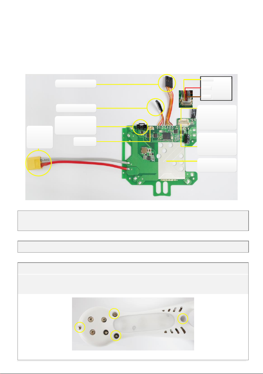
To battery
Note: only
3S battery
is allowed
GPS port, Connect
GPS module with
GPS cable
To X3 port on MC
To EXP port on MC
Installation
position for MC
Reserved
Connect to
wireless video
transmitter with a
3pin cable
Connect to 8pin
port on H3-2D
Gimbal with an
8pin cable
wireless
video
transmitter
Signal
VCC
GND
P330CB-H3-2D Board(1), LED Board(1), 8pin cable(1), 3pin cable(1), 3M Fixing pad(1)
Spare screws: Phillips-head screws M2.0*6.5(5) and M1.6*4(3)
Allen screw driver, Phillips-head screw driver, soldering iron, cable ties, scissors
1、Disassemble the 4 propellers of the PHANTOM.(Disassemble 4 prop guards too if they are assembled)
2、Remove screws on 4 arms to open the top cover of PHANTOM. Below shows the positions of screws to be
removed on one arm.
Fig.1 Screws to be removed
P330CB-H3-2D Board is designed to replace the center board inside the PHANTOM. P330CB-H3-2D has
integrated PMU(Power manage unit) and GCU(Gimbal control unit),and has added ports for wireless video
transmission module and Zenmuse H3-2D to enhance the compatibility with H3-2D.
For NAZA-M Firmware version V3.12 or above,Assistant software version V2.12 or above.
Introduction
In the box
Self-prepared tools
Assembly steps
©2013 DJI Innovations. All Rights Reserved. 1|
Page 2

3、Disassemble the original center board inside the PHANTOM
(1)Cut off the cable ties to release the USB cable fixing to the center board.(A1)
(2)Disconnect the connections with the MC.(B1-B2)
(3)Desolder the ESC cables(C1-C4) connected to the center board.
(4)Remove the screws(D1-D4)to disassemble the original center board.
A1
A1
B1
B1
B2
B2
C3
C3
C2
C2
C1
C1
C4
C4
D3
D3
D2
D2
D1
D1
D4
D4
Fig.2 Disassemble items
To M4 port on MC
To LED port on MC
To M1 port on MC
To M3 port on MC
To GPS port on
P330CB-H3-2D
To X2 port on MC
To M2 port on MC
Fig.3 Original center board is disassembled
©2013 DJI Innovations. All Rights Reserved. 2|
Page 3

4、Disassemble the original LED Board, assemble the new LED Board
LED Shell
Screws
LED
Board
Fig.4 Replace the LED Board
5、Assemble P330CB-H3-2D
(1)Remove the MC from the original center board and assemble the MC on P330CB-H3-2D Board with 3M
fixing pad, make sure the MC is assembled in the direction shown below.
(2)Assemble the P330CB-H3-2D Board with screws(D1-D4).
(3)Solder the ESC cables to the P330CB-H3-2D Board as VCC to V and GND to G.
(4)Connect the cables to the MC then tidy and check the final connections.
C3
C3
C2
C2
C1
C1
C4
C4
D3
D3
D2
D2
D1
D1
D4
D4
Fig.5 Assemble and solder
©2013 DJI Innovations. All Rights Reserved. 3|
Page 4

Push off the white
soft plug, then
make the 8pin
cable thread the
hole on the
bottom board of
M2 arm
Connect to
wireless
video
transmitter
Connect the
8pin cable to
the 8pin port
on the gimbal
before you
mount the
Damping unit
and gimbal
Fig.6 Final connections
6、Reassemble the covers and propellers, please make sure the cover points to the right nose
direction and the rotating marks on propellers are in accordance with the marks on the cover.
©2013 DJI Innovations. All Rights Reserved. 4|
 Loading...