

Page 1

A3-AG/N3-AG
Agriculture Kit
User Manual
2017.08
V2.0
Page 2

Contents
A3-AG Introduction
N3-AG Introduction
Agriculture Management Unit (AMU) Introduction
Installation
Overview
Start the Installation
System Functions
Flight Modes
Operation Modes
Operation Resumption
Empty Tank Warning
Return to Home (RTH)
Attitude Control When One Motor Output Fails
Propulsion System Protection
System Data Protection
Altitude Stabilization System
Redundancy System
Flight
Operation Environment
Flight Limits and No-Fly Zones
Pre-Flight Checklist
Compass Calibration
Flight Control
DJI Assistant 2
Installation and Launching
Using DJI Assistant 2
Appendix
Specications
Flight Status LED Indicator Descriptions
FAQ
3
6
9
10
10
13
23
23
23
29
32
33
35
35
35
36
37
39
39
39
41
41
43
44
44
44
46
46
48
49
2017 DJI All Rights Reserved.
2
©
Page 3
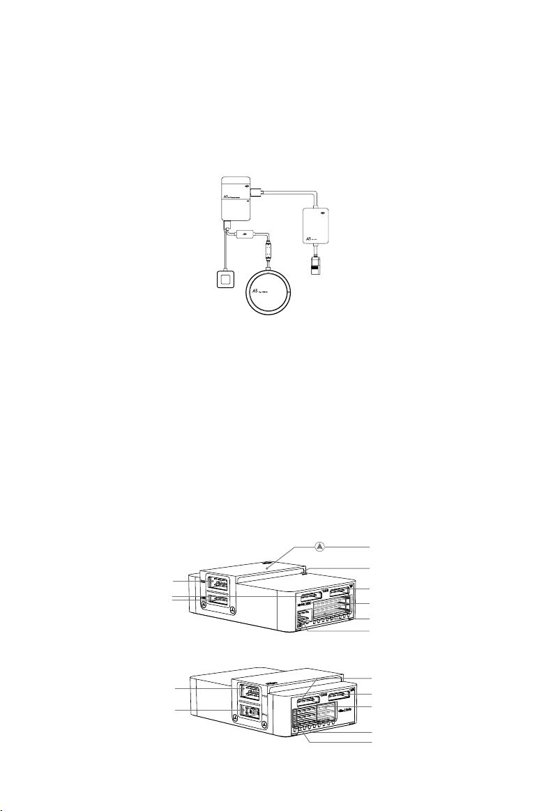
A3-AG Introduction
The A3-AG Agriculture Flight Control System, based on the DJI A3 flight control system, is
designed for agriculture applications. It consists of flight controller, GPS-Compass Pro, PMU
(Power Management Unit) and LED module. The A3-AG can be upgraded to the A3-AG Pro triple
modular redundancy system by installing two upgrade kits.
A3-AG and A3-AG Pro Parts
Flight Controller
Feature Highlights
1. Built-in inertial sensors for the measurement of aircraft attitude and built-in pressure sensor for
the detection of aircraft altitude.
2. Support for multiple receiver types. If used with the DJI Datalink 3, the A3-AG has direct
access to features in the DJI MG app such as intellignt planning and operation.
3. M1 to M8 are used to connect the ESCs of the aircraft and iESC for DJI Intelligent ESC
communication.
10
3
1
2
9
4
5
6
7
8
11
12
13
14
15
2017 DJI All Rights Reserved.
©
3
Page 4

A3-AG/N3-AG
User Manual
1. IMU1 Port
Communicates with the IMU Pro module.
2. CAN1 Port
Dedicated DJI CAN-Bus port.
Communicates with the A3 GPS-Compass
Pro or other DJI devices (e.g. Agriculture
Management Unit (AMU) or Real Time
Kinematic (RTK) GPS system).
3. Orientation Arrow
The FC module should be mounted with
the arrow pointing in the specied direction
(Orientation can be set in the DJI Assistant 2).
4. Status Indicator
Indicates the status of the ight controller
and triple modular redundancy system.
5. RF Port
Communicates with the DJI Datalink 3 Air
System.
6. iESC Port
Communicates with the DJI Smart ESC
7. M1-M8 Pins
Connects to the corresponding ESC
PWM port for each motor.
8. LED Port
Communicates with the LED module.
9. IMU2 Port
Communicates with the IMU Pro module.
10. PMU Port
Derives power from the PMU.
11. CAN2
Reserved port.
12. API Port
Reserved port.
13. F5-F8 Pins
Multifunction PWM I / O ports.
14. F1-F4 Pins
Multifunction PWM output ports.
15. S-Bus Port
Communicates with a DJI DR16 or
S-Bus receiver.
using the Smart ESC Communication Cable.
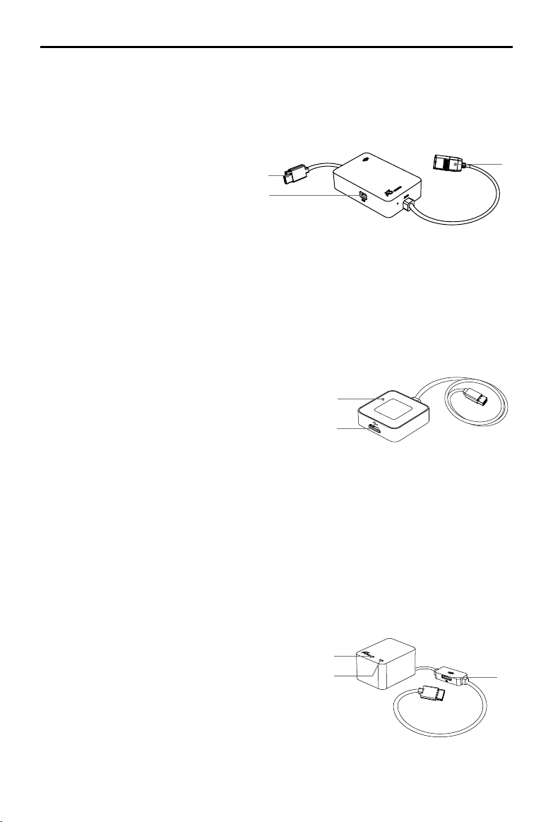
GPS-Compass Pro Module
The GPS-Compass Pro module has a built-in GPS and compass. The compass is used for
geomagnetic eld measurements. Compass calibration is required before use. DO NOT use or
store the compass in environments with ferromagnetic materials.
Note that the GPS-Compass Pro module in the Upgrade Kit is the same as the one in the A3-AG
package.
1. Status Indicator
Indicates the status of the GPS-Compass Pro
module and triple modular redundancy system.
2. Orientation Arrow
1
2
3
The GPS-Compass Pro module should be
mounted with the arrow pointing to the aircraft’s
nose.
3. Extended CAN1 Port
Dedicated DJI CAN-Bus port. Communicates with DJI devices (e.g. Agriculture Management
Unit (AMU) or Real Time Kinematic (RTK) GPS system).
2017 DJI All Rights Reserved.
4
©
Page 5
A3-AG/N3-AG
User Manual
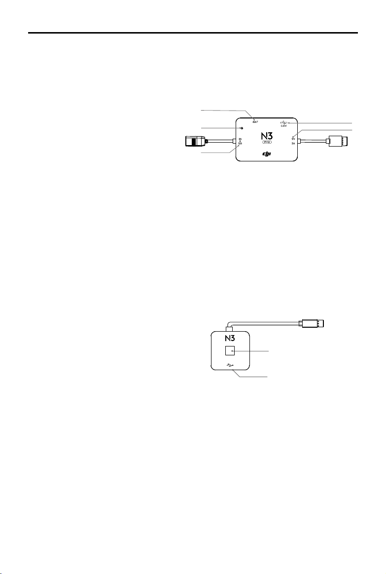
PMU Module
Supported the LiPo batteries. with built-in PMU providing power for the whole Flight Control
System and low voltage protection function.
1. Power Port (9V 3A)
Connected to the Flight Controller for
power supply.
2. iBAT
1
2
Reserved.
3. 3S-12S
Derives power from the LiPo batteries.
LED Module
The LED Module has an integrated LED Indicator and Micro USB port.
A. The LED is mainly for ight control system status indication during ight (e.g. Flight Mode).
B. In addition, there is a Micro USB port for rmware upgrades via DJI Assistant 2.
1. Flight Status Indicator
Indicates the status of the ight control system.
1
2. Micro USB Port
Used to congure and upgrade the A3 or A3 Pro
2
via DJI Assistant 2.
3
IMU Pro Module (included in the upgrade kit)
Includes built-in inertial sensors for the measurement of aircraft attitude and a built-in pressure
sensor for detecting aircraft altitude. The IMU Pro has been calibrated before delivery and
should be used under the specied temperature range. Using the IMU Pro outside the specied
temperature range may have a negative eect on the IMU’s performance.
1. Orientation Arrow
The IMU Pro module should be mounted with the arrow pointing to the specied orientation
(Orientation can be set in the DJI Assistant 2).
2. Status Indicator
Indicates the status of the IMU Pro module and triple
1
2
modular redundancy system.
3. CAN1 GPS Port
Communicates with the GPS-Compass Pro module.
2017 DJI All Rights Reserved.
©
3
5
Page 6
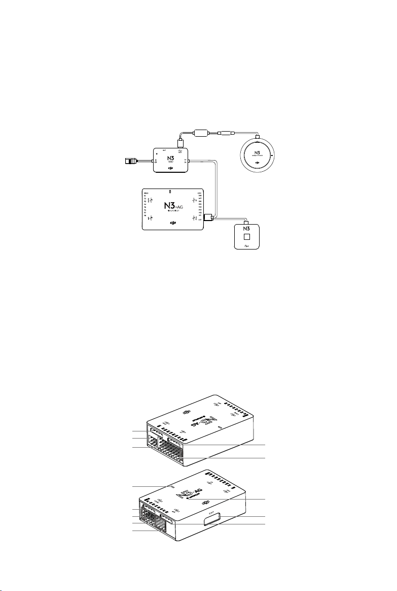
N3-AG Introduction
The N3-AG Agriculture Flight Control System, based on the DJI N3 flight control system, is
designed for agriculture applications. It consists of ight controller, GNSS-Compass Pro, PMU
(Power Management Unit) and LED module. The N3-AG can be upgraded to the N3-AG Pro
redundancy system by installing an upgrade kit.
LED
N3-AG Parts
Flight Controller
Feature Highlights
1. Built-in inertial sensors for the measurement of aircraft attitude and built-in pressure sensor for
the detection of aircraft altitude.
2. Support for multiple receiver types. If used with the DJI Datalink 3, the A3-AG has direct
access to features in the DJI MG app such as intellignt planning and operation.
3. M1 to M8 are used to connect the ESCs of the aircraft and iESC for DJI Intelligent ESC
communication.
2017 DJI All Rights Reserved.
6
©
1
2
3
6
7
8
9
10
5
4
13
12
11
Page 7
A3-AG/N3-AG
User Manual
Flight Controller
1. PMU Port
Derives power from the PMU module.
2. LED Port
Communicates with the LED module.
3. M1-M8 Pins
Connects to the corresponding ESC
PWM port for each motor.
4. iESC Port
Communicates with the DJI Smart ESC
using the Smart ESC Communication
Cable.
5. RF Port
Communicates with the DJI Datalink 3
Air System.
6. Status Indicator
7. CAN2 Port
CAN Bus port (Reserved port).
8. S-Bus Port
Communicates with a DJI DR16 or S-Bus
receiver.
9. F1-F4 Pins
Multifunction PWM output ports.
10. F5-F8 Pins
Multifunction PWM I / O ports.
11. API Port
Reserved port.
12. EXP Port
Extended port (Communicates with the
A3 upgrade kit).
13. Orientation Arrow
The ight controller orientation arrow.
Indicates the status of the ight controller.
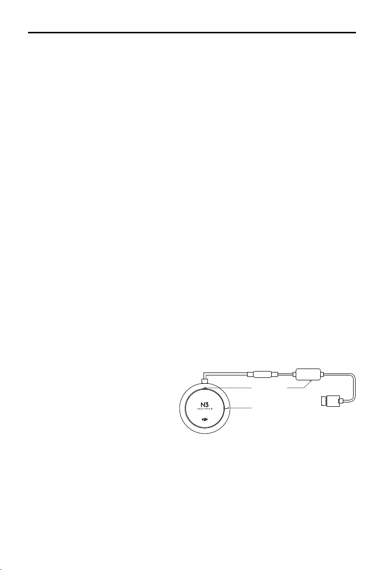
GNSS-Compass Module
The GNSS-Compass module has a built-in GPS/GLONASS and compass. The compass is used
for geomagnetic eld measurements. Compass calibration is required before use. DO NOT use or
store the compass in environments with ferromagnetic materials.
1. Orientation Arrow
The GNSS-Compass module
should be mounted with the arrow
pointing toward the aircraft nose.
2. GNSS-Compass Status Indicator
Indicates the status of the GNSS-
Compass Module.
3. Extended CAN1 Port
Dedicated DJI CAN-Bus port. Communicates with a DJI device.
1
3
2
2017 DJI All Rights Reserved.
©
7
Page 8
A3-AG/N3-AG
User Manual
PMU Module
Supported the LiPo batteries. with built-in PMU providing power for the whole Flight Control
System and low voltage protection function.
1. iBAT
Reserved.
1
2. Power Status Indicator
Indicates the power status of the
2
ight control system.
3. 3S-12S
3
Derives power from LiPo battery.
4. Power Port (9V 2A)
Connected to the Flight Controller for power supply.
5. CAN1 Port
Connected to the GNSS-Compass module.
LED Module
The LED Module has an integrated LED Indicator and Micro USB port.
A. The LED is mainly for ight control system status indication during ight (e.g. Flight Mode).
B. In addition, there is a Micro USB port for rmware upgrades via DJI Assistant 2.
1. Flight Status Indicator
Indicates the status of the flight control
system.
2. Micro USB Port
LED
1
Used to congure and upgrade the N3 via DJI
Assistant 2.
2
5
4
2017 DJI All Rights Reserved.
8
©
Page 9
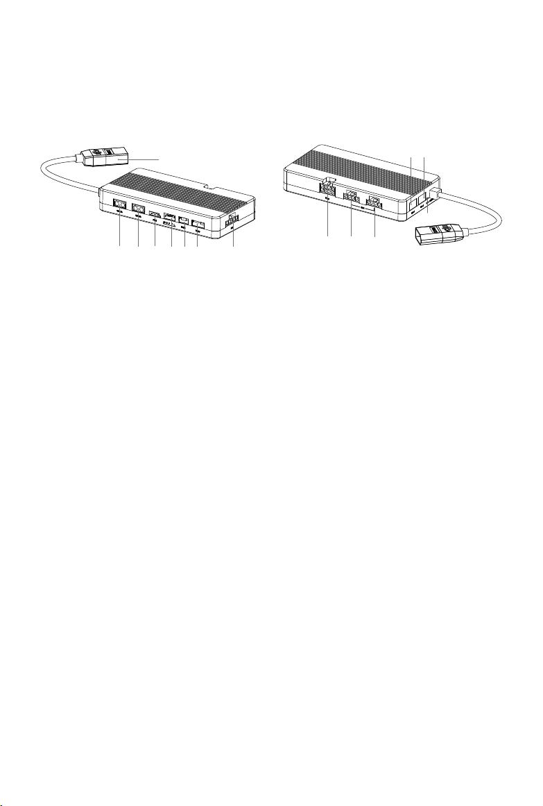
Agriculture Management Unit (AMU) Introduction
The Agriculture Management Unit (AMU) is equipped with essential expansion ports to support
DJI modules such as Altitude Stabilization System, delivery pump, RTK.
8
1 2 3 4 5 6 7
1. 12V 2A
Reserved power port, max operating
voltage / current: 12V@2A
2. 15V 6A
Reserved power port, max operating
voltage/current: 15V@6A. Users can
connect a DJI data protection module to
this port for power supply.
3. PWM
Reserved port.
4. Level Meter & Flow Meter Port
Reserved port.
5. D485
Reserved port.
6. Radar
Connected the DJI Altitude Stabilization
System.
7. RTK
Connected to the DJI D-RTK device.
8. Power Port
XT60 port. Connected to an external
power supply (6S - 12S).
12 13
14
9 10 11
9. Pump
Connected to the DJI integrated pump.
10. CAN
CAN Bus port. Connected to the CAN1
port on the ight controller.
11. CAN
Same as the 10th port.
12. UART I
Battery data communication port
(reserved).
13. UART II
Battery data communication port
(reserved).
14. Working Status Indicator
It will glow solid green when the device
is working normally. It will be solid red
when the device is abnormal or during
rmware update.
2017 DJI All Rights Reserved.
©
9
Page 10
Installation
Installation steps are similar for both the N3-AG and A3-AG. The descriptions in this chapter use
the N3-AG as an example. Unless specied, the following context can also be applied to the A3-
AG installation.
Overview
Installation Procedure
Read this section carefully and follow the procedures below to install your ight control system,
otherwise the ight control system may not normally work.
1
Ensure all parts are in good condition.
2
Mount the parts to your airframe and connect them properly.
3
Launch the DJI Assistant 2 and congure the parameters.
4
Ensure the motor, remote controller channels and Failsafe settings are correct.
5
Ensure the devices connected to the ight controller are working normally and correctly set in
DJI Assistant 2.
Preparation
Equipment
Ensure you have a suitable airframe, remote controller system, ESCs and battery to use with the
ight control system. Below is a list of compatible equipment.
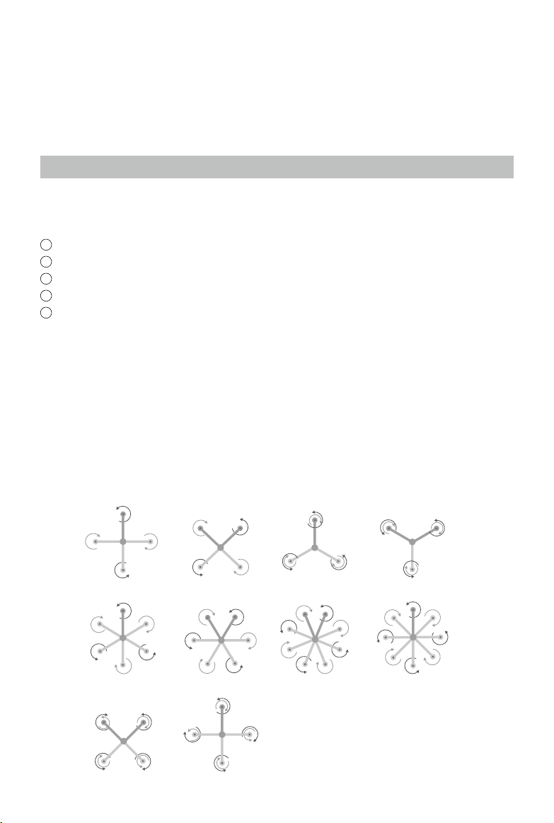
A. Airframes
The following airframes are supported. Choose an airframe and assemble it properly.
Remember to select the corresponding airframe type in DJI Assistant 2 after assembling the
airframe and connecting the cables.
2017 DJI All Rights Reserved.
10
©
X4I4
I6
X8 IX8
V6 I8V8
IY6 Y6
Page 11
A3-AG/N3-AG
User Manual
The arrow directions in the above diagram indicate the rotation direction of the motor/
propeller. Dark colored arm (s) indicate the direction of the aircraft’s nose.
For coaxial propellers, dark colored propellers are at the top and gray colored propellers
are at the bottom. Otherwise, all propellers are at the top.
B. Remote Controller System
The following remote controller systems are supported. Whatever type of receiver is used,
please make sure that the receiver and remote controller are linked properly before use. Be
sure to link the receiver and remote controller according by following all the procedures in
the remote controller and receiver user manual, and according to the congurations in DJI
Assistant 2.
DJI Datalink 3
DJI Datalink 3 lets you use DJI MG app to congure the ight control system parameters and
utilize intelligent agricultural operation.
DR16
The DR16 receiver does not support DJI MG app.
S-Bus
The S-BUS receiver does not support DJI MG app.
There is no need to enable the Failsafe function on the remote controller. Once the
receiver loses signal from the remote controller, the controller unit will enter Failsafe
mode automatically, and the aircraft will hover or return-to-home & land according to the
Failsafe congurations in DJI Assistant 2.
C. Propulsion System
ESC
ESC output should be 400Hz. DJI Propulsion systems are recommended.
The iESC port can connect to the DJI Smart ESC Communication Cable if using the DJI
Intelligent ESC.
Propeller and Motor
It is required to use with Propeller and Motor of more than 2400rpm.
D. Battery
If using a LiPo battery (3S - 12S), only the voltage information and low voltage protection are
available.
2017 DJI All Rights Reserved.
©
11
Page 12
A3-AG/N3-AG
User Manual
Preparing DJI Assistant 2
Download DJI Assistant 2
DJI Assistant 2 is used to congure the ight control system.
http://www.dji.com/agriculture-solution/info#downloads
Supports Windows 7 (or later) or Mac OS X 10.11 (or later).
Installing DJI Assistant 2
DJI Assistant 2 will guide you through setting the Flight Control System’s parameters. Carefully
follow the on-screen prompts to congure the Flight Control System.
Installing and Running on Windows
Supports Windows 7, Windows 8, Windows 10 (32 or 64 bit).
1. Connect the Micro USB port on the LED module to a PC via a Micro USB cable.
2. Run the software assistant installer and follow the prompts to nish installation.
3. Double click the software assistant icon on your Windows desktop to launch the software.
Installing and Running on Mac OS X
Supports Mac OS X 10.11 (or later).
1. Run the DMG installer and follow the prompts to nish installation.
2. If using Launchpad to run DJI Assistant 2 for the rst time, Launchpad will not allow access
because the software has not been reviewed by the Mac App Store.
3. Locate the DJI Assistant 2 icon in the Finder, press the Control key and then click the DJI
Assistant 2 icon (or right-click the DJI Assistant 2 icon using a mouse). Choose Open from the
shortcut menu, click Open in the dialog box and the software will launch.
4. After the rst successful launch, direct launching of the software can be achieved by double-
clicking the DJI Assistant 2 icon in the Finder or using Launchpad.
DJI Assistant 2 works exactly the same way on Mac OS X and Windows. The DJI
Assistant 2 screenshots that appear in this manual are taken from the Windows version.
For safety reasons, do not use the power battery for power supply or remove the
propellers from the motors before connecting to the Assistant Software.he Windows
version.
2017 DJI All Rights Reserved.
12
©
Page 13
A3-AG/N3-AG
User Manual
Start the Installation
Important: Strictly follow the provided guidelines. Failure to do so may lead to unexpected
ight behavior or serious accidents.
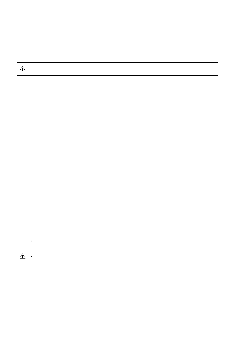
Flight Control System Installation
Mounting the Flight Controller
Mount the Flight Controller with the Orientation Arrow pointing to the front, back, left or right.
Make sure the module is parallel to the aircraft and then x it onto the aircraft with double-faced
adhesive tape. Congure the parameters in DJI Assistant 2 and select the direction in which you
mounted the Flight Controller. We recommend mounting the Flight Controller with the Orientation
Arrow pointing forward.
Built-in IMU
The top side should be facing up. DO NOT mount upside-down.
Remember to warm up the battery if operating in cold weather.
Mount the ight controller at a low vibration position. The sides of the ight controller
should be precisely parallel to the aircraft body. Based on our experience, there is less
vibration near the aircraft’s center of gravity.
The ight controller is NOT water-proof or oil-proof.
Check the double-faced adhesive tape regularly to ensure the IMU is fixed firmly in
place.
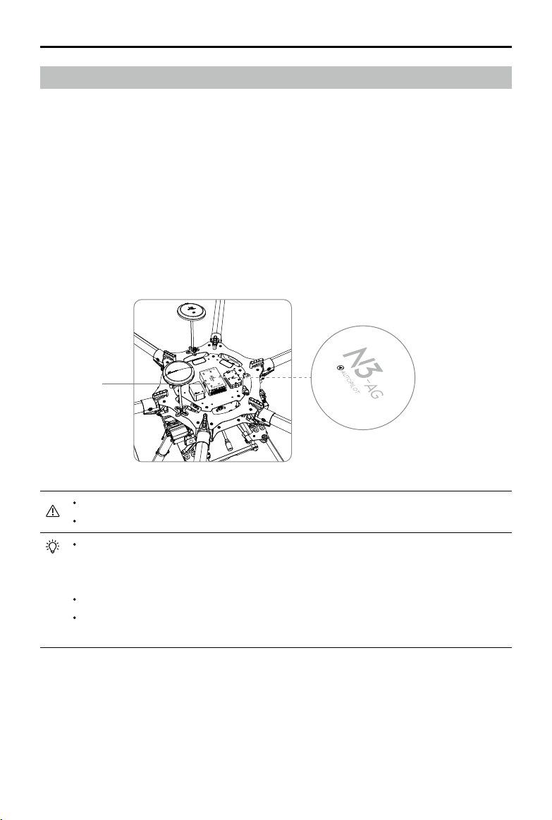
Mounting the GNSS-Compass Module*
Follow the procedures below to mount the GNSS-Compass bracket and the GNSS-Compass
module. The GNSS-Compass module included in the Upgrade Kits is the same as the one in the
N3 package.
* For the A3-AG, it is GPS-Compass Pro module.
2017 DJI All Rights Reserved.
©
13
Page 14
A3-AG/N3-AG
User Manual
1. Use the M2.0×4 screws to assemble the GNSS-Compass bracket with the Ball End Hex Key
assistant. The longest one is recommended.
2. With the M2.5×7 screws and M2.5×3.4 nuts, mount the bracket on the aircraft.
3. Ensure the GNSS-Compass arrow is pointing to the aircraft nose and then x it onto the top of
the GNSS-Compass bracket. Try to keep it parallel to the aircraft.
Usage Requirements
1. The DJI logo should be facing the sky, with the orientation arrow pointing directly to the nose
direction; otherwise you may experience take o failure.
2. Fly the aircraft in an open space without buildings or trees; otherwise the GPS satellite number may
be aected.
3. The compass is sensitive to magnetic interference. Always keep the compass module away
from magnetic elds. Otherwise, the compass module may become damaged and lead the
aircraft to work abnormally or even lose control.
4. Select a bracket of appropriate length for you aircraft to avoid interference with the compass.
The length is based on the airframe type and the mounting position and so on. Ensure that
there will not any compass warning when the aircraft is ying with maximum load and can
normally y.
2017 DJI All Rights Reserved.
14
©
Page 15
A3-AG/N3-AG
User Manual
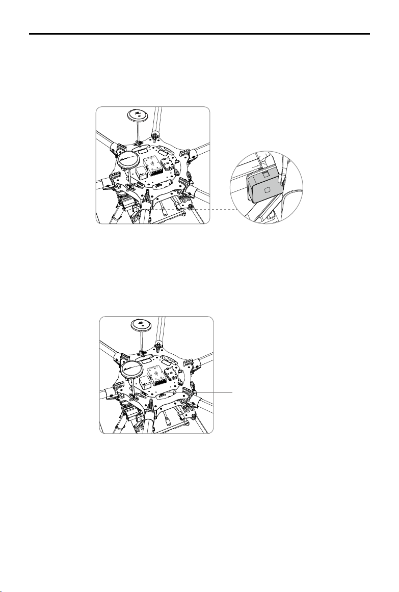
Mounting the LED Module
Mount the LED module in a position to ensure it remains visible during flight. The LED bracket
included can be used to x the LED module onto the aircraft.
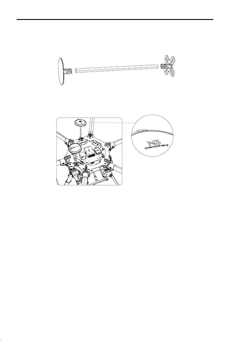
Mounting the PUM Module
Mount the PMU module to an unobstructed position on the bottom of the aircraft’s upper plate for heat
dissipation.
PMU
2017 DJI All Rights Reserved.
©
15
Page 16
A3-AG/N3-AG
User Manual
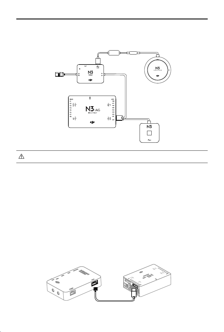
Flight Control System Connection
Follow the below diagram to connect the ight control system, and use the cable ties to tidy the
cables.
LED
The ight control system’s shell is connected to the whole system’s ground.
Connecting to the Airframe and its Equipment
Ensure you have a suitable airframe, remote controller system, ESCs and battery to use with
the flight control system. Strictly follow the provided guidelines. Failure to do so may lead to
unexpected ight behavior or serious accidents.
Connecting to a Receiver
Select the RF port or the S-Bus port for dierent types of receivers.
DJI Datalink 3
Connect the DJI Datalink 3 receiver DBUS port to the Flight Controller RF Port with included RF
Cable.
RF Cable
2017 DJI All Rights Reserved.
16
©
Page 17

A3-AG/N3-AG
User Manual
DR16 Receiver
Connect the DR16 receiver DBUS port to the Flight Controller S-Bus Port with a servo cable.
S-BUS Receiver
Connect the S-BUS receiver to the Flight Controller S-Bus Port with a servo cable.
S-Bus Receiver
Connecting to the ESCs
S900 Connection Diagram
1. Connect the M1-M6 ports on the bottom board of the S900 to the M1-M6 ports on the Flight
Controller in order.
2. The iESC port can connect to the DJI Smart ESC Communication Cable if using the DJI
Intelligent ESC.
G
B
A
P01603.01
2017 DJI All Rights Reserved.
©
17
Page 18

A3-AG/N3-AG
User Manual
Other Airframe Type Connection Diagram
Connect the ESC ports to the ESC ports on the Flight Controller. The diagram below
uses type V6 for example.
Connecting to a Battery
Connect the PMU to the Flight Controller PMU port, and then connect the battery (3S - 12S,
11.1V - 51V) to the PMU.
3S- 12S
Ensure the 3S battery voltage is higher than 11.1V, as low battery level may eect the
battery life and decrease the PMU stability.
AMU Installation
Installation
Mount the AMU to an appropriate position on the aircraft for heat dissipation.
Connection
1. Connect the CAN Bus port on the AMU to the CAN1 port on the ight controller or extended
CAN1 port on the GNSS-Compass / GPS-Compass Pro module via the included CAN-Gimbal
cable.
2. Connect the power port on the AMU to the power supply of the aircraft via an appropriate
cable.
Connect to Expansion Devices
Delivery Pump
DJI delivery pump: used with the AMU. Mount the DJI delivery pump to the desired position, and
then connect the power cable of the pump to the Pump port on the AMU.
Other pumps: Connect the ESC signal cables of the pump to the F1 and F2 ports on the ight
controller. The F1 or F2 port cannot supply power for the pump. Users should connect the pump
to an extra power supply.
2017 DJI All Rights Reserved.
18
©
Page 19

A3-AG/N3-AG
Liquid
Outlet
Liquid Inlet
User Manual
DJI Altitude Stabilization System
To ensure that the spray is evenly dispensed, a DJI Altitude Stabilization System which uses
microwave radar module can be mounted to the aircraft to maintain the same distance above the
crops at all times. It should be used with the AMU.
Mount the Altitude Stabilization System to the aircraft. Note that the microwave transmitting and
receiving surface should be horizontal and facing to the ground. Then connect the module to the
Radar port on the AMU.
Microwave
Transmitting
and Receiving
Surface
Make sure that the microwave transmitting and receiving surface of the Altitude
Stabilization System is horizontally facing down and unobstructed.
DJI Data Protection Module
The DJI Data Protection Module enables the aircraft to retain vital system data (e.g. Point A, Point
B, breakpoint) for about 30 seconds after the aircraft is powered o. This function allows you to
rell the spray, change battery, etc. The recorded Point A, Point B and breakpoint are still available
if you power on the aircraft within the working time (30 seconds) of the data protection function.
For the N3-AG: Connect the CAN cable of the module to the extended CAN1 port on the GNSS-
Compass module. If using the AMU, connect it to the extended CAN1 port on the CAN-gimbal
cable.
For the A3-AG: Connect the CAN cable of the module to the CAN1 port on the ight controller or
the extended CAN1 port on the GPS-Compass Pro.
2017 DJI All Rights Reserved.
©
19
Page 20

A3-AG/N3-AG
User Manual
ParameterConguration
Launch DJI Assistant 2 and follow the prompts to complete conguration.
1
Ensure the ight control system is properly powered on.
2
Connect the Micro USB port on the LED module to a PC via a Micro USB cable.
3
Run DJI Assistant 2. Note that you may be asked to register for rst time use.
4
Follow the prompts to upgrade the rmware to the latest version*.
5
Select the airframe type.
6
Configure the Flight Controller, IMU and GNSS-Compass / GPS-Compass Promounting
parameters.
7
Select the receiver type and congure the channel mapping.
8
Make sure the motors are rotating in correct direction. If not, change the rotating direction.
9
Congure the function channels.
10
Fly in the simulator to check that all functions is working normally.
Ensure to connect all modules before power on.
Ensure to power cycle the battery after rmware upgrade.
Remote Controller Channel Mapping
Complete remote controller channel mapping to the default flight controller channels of A_B
Button, Spray Switch, C1 and C2 Function Switch to perform tasks remotely. Basic agricultural
functions can be achieved through at least nigh channels (ve switches). 12 channels (8 switches)
are required for all functions.
Remote controller type is SBUS by default. See the table below for the recommended type of
switch for each of the remote controller channels. If using Datalink 3, choose “Datalink 3” for
remote controller type in DJI Assistant 2. Refer to Datalink 3 User Manual for channel settings.
2017 DJI All Rights Reserved.
20
©
Page 21

A3-AG/N3-AG
User Manual
No. Name
SBUS Mapping
Channel by Default
Type of Switch Functions
1 A_B Button Channel 5 3 position To record Point A and B.
2 RTH Switch Channel 6 2 or 3 position For RTH.
To switch the ight mode.
When using a 3 position switch,
the three positions are F-mode,
A-mode and P-mode by default.
3 Flight Mode Switch Channel 7 2 or 3 position
When using a 2 position switch,
the two positions are F-mode
and P-mode by default. And the
F-mode position can be set to
A-mode in DJI Assistant 2.
To switch the operation mode.
When using a 3 position switch,
the three positions are S, M and
Operation Mode
4
Switch
Channel 8 2 or 3 position
M+ by default.
When using a 2 position switch,
M+ function should be disabled in
DJI Assistant 2, and then the two
positions will be S and M.
5 Spray Switch Channel 9 2 or 3 position To start or stop spraying.
6 Spray Rate Dial Channel 10 Knob To adjust the maximum spray rate.
In S mode: to adjust ying speed
7 C1 Function Switch Channel 11 2 or 3 position
to the lower one.
In M+ mode: to y the aircraft left.
In S mode: to adjust ying speed
8 C2 Function Switch Channel 12 2 or 3 position
to the faster one.
In M+ mode: to y the aircraft right.
1. A_B Button
The 3 positions of the switch should be set as A, null, B.
Toggle the switch to A from any other position to record Point A of the operation route.
Toggle the switch to B from any other position to record Point B of the operation route.
2. RTH Switch
Toggle the switch to the valid position to enter Smart RTH, while toggle it to the invalid position to
cancel the RTH.
3. Flight Mode Switch
The flight controllers features F-mode, A-mode and P-mode (refer to System Functions for
details). Toggle this switch to select a ight mode.
3-position switch: F-mode, A-mode, P-mode
2017 DJI All Rights Reserved.
©
21
Page 22

A3-AG/N3-AG
User Manual
2-position switch: P-mode and F-mode are by default. F-mode can be changed to A-mode in DJI
Assistant 2.
4. Operation Mode Switch
The ight controller features S, M and M+ operation modes (refer to System Functions for details).
Toggle this switch to select an operation mode.
3-position switch: S, M, M+.
2-position switch: disable M+ mode and enable S and M mode in DJI Assistant 2.
5. Spray Switch
In Manual Operation mode, F-mode or A-mode, toggle the switch to the valid position to spray
liquid, and toggle to the invalid position to stop spraying. In Smart Operation mode and Manual
Plus Operation mode, spraying will start and stop automatically. It cannot be controlled by users.
F1 and F2 channels are for the pump control by default. The will output standard ESC control
signal. Connect the ESC to F1 or F2 channel to control the pump. Mapping F3 to F8 channels for
pump control in DJI Assistant 2 if you can more pumps.
6. Spray Rate Dial
Mapping is not necessary if the function is not used.
Turn the dial to adjust spray rate, and the pump motor rotating speed from F1 or F2 will be
changed. The value of the dial is from -1000 to 1000. The motor will stop when the value is
-1000, while the motor will rotate at full throttle when it is 1000.
The value of the dial will be saved in the ight controller, which will not be lost after powered o. It
will keep the last value when powering the ight controller on next time.
7. C1 Function Switch
Mapping is not necessary if the function is not used.
In S mode: to adjust ying speed to the lower one.
In M+ mode: to y the aircraft left for one line spacing.
8. C2 Function Switch
Mapping is not necessary if the function is not used.
In S mode: to adjust ying speed to the faster one.
In M+ mode: to y the aircraft right for one line spacing.
2017 DJI All Rights Reserved.
22
©
Page 23

System Functions
Flight Modes
The ight control system includes three ight modes: P-mode (Positioning), A-mode (Attitude),
and F-mode (Functions). Toggle the Flight Mode switch on the remote controller to one of the
three modes.
P-mode (Positioning): The aircraft uses GNSS for positioning and it can only maintain attitude
stabilization when GNSS signal is weak. In P-mode, users can start the motors, record Point A
and B, and enter Smart operation mode (A-B Route) when the GNSS signal is strong. If using the
D-RTK*, it can provide centimeter-level positioning accuracy.
A-mode (Attitude): GNSS is not used for positioning, and aircraft can only maintain altitude using
the barometer. Aircraft can still record its position and return to the Home Point if a GNSS signal
is present.
F-mode (Function): The aircraft uses GNSS for positioning and it can only maintain attitude
stabilization when GNSS signal is weak. If using the D-RTK*, it can provide centimeter-level
positioning accuracy. If using Datalink 3, plan tasks in advance in the DJI MG app and the aircraft
will automatically perform the selected task after entering F-mode with a strong GNSS signal. The
DJI MG app will display “Route”. Refer to Datalink 3 User Manual for details.
The aircraft will always y in P-mode by default after powering on regardless of the Flight
Mode switch position. If the Flight Mode switch is at A or F when powered o, set the
switch to any other position and then to A or F after powering on the aircraft to use A-mode
or F-mode.
If using the D-RTK*, ensure to start the motors and take o after waiting for RTK ready (the
ground system indicator blinks green). When the D-RTK is working normally, the ight
status indicator will alternately show the current ight mode and the D-RTK status (blue).
Operation Modes
When the Flight Mode Switch is set to P, the system provides Smart, Manual, and Manual Plus
operation modes. Switch to one of the three modes via the Operation Mode switch on the remote
controller.
Smart operation mode (S): When the aircraft is in P-mode and the GNSS signal is strong, set the
switch to this mode after recording Points A and B. The aircraft will y and spray liquid along the
specied route. If using the Datalink 3, the DJI MG app will display “A-B Route.”
Manual operation mode (M): Users can control all the movements of the aircraft and spray liquid
manually. If using the Datalink 3, the DJI MG app will display “Manual Route.”
* Only A3-AG supports the D-RTK.
2017 DJI All Rights Reserved.
©
23
Page 24

A3-AG/N3-AG
User Manual
Manual Plus operation mode (M+): Users can control the movement of the aircraft, but ying
speed is restricted and heading is locked. Use the C1 or C2 buttons on the remote controller to
steer the aircraft left/right for one line spacing. If using the Datalink 3, the DJI MG app will display
“M+ Route.”
Smart Operation Mode
In Smart operation mode, the aircraft will travel along a pre-planned route. Operation resumption,
data protection, and the Altitude Stabilization System are available in this mode. Use the C1
and C2 buttons on the remote controller to adjust ying speed. The spray rate will be adjusted
automatically according to the ying speed. Smart operation mode is recommended for large,
rectangular spray areas.
Operation Route
The aircraft will travel along a pre-designated square zig-zag route after recording turning points
A and B. Under optimal working conditions for the Altitude Stabilization System, the aircraft
maintains distance from the vegetation. The length of the dotted lines, called Operation Gap (Line
Spacing), can be adjusted in DJI Assistant 2 or the DJI MG app.
B
L1
L4 R5
L5
A
L2 R3
L3
L6
Route L Route R Legends
B R1
A
R4
…………
- - - -
Operation Gap
(Line Spacing)
R2
R6
Turning Point
Operation Procedure
Maintain line of sight of the aircraft at all times.
Set the Flight Mode switch to P when GNSS signal is strong. Otherwise, Smart
operation mode may be unreliable.
Always inspect operating environments before ying.
Set the remote controller’s Flight Mode Switch to P when a strong GNSS signal is present. In
addition, set the Operation Mode switch to M. Instructions vary according to the type of your
remote controller (SBus or Datalink 3). Follow the steps for the corresponding remote controller.
2017 DJI All Rights Reserved.
24
©
Page 25

A3-AG/N3-AG
User Manual
SBus
1. Record Points A and B in Order
Users cannot set the Operation Mode switch to Smart operation mode until they have
recorded points A and B.
Fly the aircraft to the starting point, depicted as Point A/B, hover, and then toggle the A_
B switch on the remote controller from any other position to position A/B. The Flight Status
Indicator will blink red/green after recording the starting points.
Points A and B can only be recorded when the aircraft is hovering in Manual operation
mode.
Update Point B by ying the aircraft to a new position to record. Note that if you update
Point A, you must also update Point B.
It is recommended to keep the direction of Point A to B parallel to one side of the
rectangular spray area for optimal eect.
2. Conguring Aircraft Altitude
If using the Altitude Stabilization System, configure the desired altitude in the DJI MG app
and adjust the aircraft altitude to a value within the working range of the Altitude Stabilization
System (2-3.5 m) by using the throttle stick before entering Smart operation mode. The
Altitude Stabilization System will start working automatically and maintain the spraying distance
between aircraft and vegetation. Refer to the Altitude Stabilization System for details.
3. Using Smart Operation Mode
Set the remote controller’s Flight Mode switch to P and ensure that a strong GNSS signal is
present (the Flight Status Indicator blink purple slowly), then set the Operation Mode switch to
S to enable Smart operation mode.
If, after recording Points A and B, you y the aircraft more than ve meters away from
Point B and then set the Operation Mode switch to S, the recorded Point B will be
erased. Toggle the Operation Mode switch to enter Manual operation mode and record
Point B again.
If, after recording Points A and B, you y the aircraft within ve meters away from Point
B and then set the Operation Mode switch to S, the aircraft will automatically y back to
Point B and hover.
4. Select the Route
Push the Roll stick left or right to select the operating pattern. Push it left for Route L and right
for Route R.
Users can select the route only in Smart operation mode when the aircraft is within ve
meters away from Point B.
2017 DJI All Rights Reserved.
©
25
Page 26

A3-AG/N3-AG
User Manual
5. Starting the Operation
a. The aircraft will be at Point B and align with the line between Points A and B with its heading
pointing toward Point B. Then it will y along Route L/R continuously.
b. Pause the operation temporarily through one of the following methods: Set the Operation
Mode switch out of Smart operation mode, initialize the RTH procedure, set the Flight Mode
switch out of P-mode, or push the Pitch or Roll stick in any direction on the remote controller.
If you want to continue the operation, follow the instructions under Operation Resumption.
c. Adjust the ying speed through the remote controller if the C1 and C2 switches have been
mapped.
Toggle the C1 switch to its valid position and then the ying speed will be reduced to the next
gear. Toggle the C2 switch to its valid position and then the ying speed will be increased to
the next gear. The four speed gears are set to 1, 3, 5, 7 m/s by default. Set them from 1 to 7
m/s and the defaulted speed gear when powered on in DJI Assistant 2.
If GNSS signal is weak during operation, the aircraft will automatically switch to Attitude
mode. Exit Smart operation mode and control the aircraft manually. If the aircraft is still in
Smart operation mode, when the aircraft regains a strong GNSS signal, it will automatically
y to the next turning point.
The line spacing can be customized from 3-10 m in DJI Assistant 2. It is set to a length of
5 m by default.
Even though the heading of the aircraft cannot be adjusted, use the throttle stick to adjust
the altitude of the aircraft to avoid obstacles in the vertical direction.
If using the control sticks to control the aircraft forward, backward, left and right during
operation, the aircraft will switch to Manual operation mode automatically. Users can
avoid obstacles manually. Refer to Manual Obstacle Avoidance for details.
The aircraft automatically sprays liquid when flying forwards or backwards, and does
not spray when flying left or right or when hovering. The spray rate will be adjusted
automatically.
Datalink 3 (DJI MG app required)
1. Record Points A and B in Order
Users cannot set the Operation Mode switch to Smart operation mode until they have
recorded points A and B.
Fly the aircraft to the starting point, depicted as Point A/B, hover, and then press Button A/
B on the remote controller or tap Point A/B onscreen. The icon for Point A/B will change from
gray to purple and the Aircraft Status Indicator will blink red/green after recording the starting
points.
2017 DJI All Rights Reserved.
26
©
Page 27

A3-AG/N3-AG
User Manual
Points A and B can only be recorded when the aircraft is hovering in Manual operation
mode.
Update Point B by ying the aircraft to a new position to record. Note that if you update
Point A, you must also update Point B.
It is recommended to keep the direction of Point A to B parallel to one side of the
rectangular spray area for optimal eect.
After recording Point A, there will be a menu prompt for work type settings. Set the
amount of pesticide per acre and work type. Use the slider to adjust work eciency.
During the task, tap the icon at the top of the screen to adjust parameters. You can also
adjust work eciency via the Settings dial on the remote controller.
The DJI MG app will display an icon of line spacing. Tap to adjust the value. The
line spacing cannot be adjusted during operation. Switch to Manual or Manual Plus
operation mode to adjust the value, then go back to Smart operation mode.
2. Select the Route
Press the C1 or C2 buttons on the remote controller to select the operating pattern. Press C1
for Route L and C2 for Route R. The default route pattern is Route R if no selection has been
made.
Users can select the route in Manual operation mode only. If the aircraft is in Smart
operation mode, select the route after switching to Manual operation mode.
3. Conguring Aircraft Altitude
Configure the desired altitude in the DJI MG app and adjust the aircraft altitude to a value
within the working range of the Altitude Stabilization System (2-3.5 m) by using the throttle
stick before entering Smart operation mode. The Altitude Stabilization System will start working
automatically and maintain the spraying distance between aircraft and vegetation. Refer to the
Altitude Stabilization System for details.
4. Using Smart Operation Mode
Set the remote controller’s Flight Mode switch to P and ensure that a
strong GNSS signal is present, then set the Operation Mode switch to S to
enable Smart operation mode.
2017 DJI All Rights Reserved.
©
27
Page 28

A3-AG/N3-AG
User Manual
If, after recording Points A and B, you y the aircraft more than ve meters away from
Point B and the Operation Mode switch is not set to S, Resume will appear on the
lower right corner of the screen when you enter Smart operation mode. Tap Resume,
and the aircraft will automatically y to Point B to re-enter Smart operation mode.
When using the control sticks to control the aircraft in Smart operation mode, the
aircraft will automatically switch to Manual operation mode, complete corresponding
ight behavior, and then hover. To resume the task, set the Operation Mode switch to
S, then tap Resume onscreen. The aircraft will return to Smart operation mode, then
resume ying along the operation route. Refer to Operation Resumption for details.
5. Starting the Operation
a. Press the remote controller’s C1 and C2 buttons simultaneously. The aircraft will align with
the line between Points A and B with its heading pointing toward Point B. Fly laterally from
Point B to L1/R1, then hover at Point L1/R1 and wait for further instructions.
b. Repeat the previous step and the aircraft will y to the next turning point along Route L/R
and hover.
c. Enable Continuous Smart operation mode by pressing and holding the C1 and C2 buttons
simultaneously for 2-4 seconds when the aircraft is hovering at any given turning point. The
Aircraft Status Indicator will turn solid purple for one second. The aircraft will then y along
Route L/R continuously. The DJI MG app will display the A-B Route.
d. To exit Continuous Smart operation mode, press and hold the C1 and C2 buttons
simultaneously for 2-4 seconds. The aircraft will y to the next turning point and hover.
The nose of the aircraft will always point from Point A to Point B regardless of ight
direction. Heading cannot be adjusted.
You will only be able to press and hold the C1 and C2 buttons for steps a to c when the
aircraft is hovering at a turning point.
If GNSS signal is weak during operation, the aircraft will automatically switch to Attitude
mode. Exit Smart operation mode and control the aircraft manually. When the aircraft
regains a strong GNSS signal, it will automatically y to the next turning point.
If you press the A or B buttons during operation, the data for Points A and B of the
current route will be erased and the aircraft will hover in place.
The line spacing can be customized from 3-10 m in DJI MG. It is set to a length of 5 m
by default.
Even though the heading of the aircraft cannot be adjusted, use the control sticks to
avoid obstacles. Refer to Manual Obstacle Avoidance for details.
The aircraft automatically sprays liquid when ying forwards or backwards, and does
not spray when ying left or right or when hovering.
2017 DJI All Rights Reserved.
28
©
Page 29

A3-AG/N3-AG
User Manual
Manual Operation Mode
Set the Operation Mode switch to M to enter Manual operation mode. You can control all the
movements of the aircraft, spray liquid via the remote controller’s Spray switch/button, and adjust
the spray rate via the remote controller’s Spray Rate knob/dial. Manual operation mode is ideal
when the operating area is small.
Manual Plus Operation Mode
Set the Operation Mode switch to M+ to enter Manual Plus operation mode. The aircraft's'
Maximum ying speed is limited (customizable in DJI Assistant 2 or the DJI MG app), the heading
is locked, and all other movement can be manually controlled in this mode. Press the C1 or
C2 buttons on the remote controller to steer the aircraft left or right. The aircraft sprays liquid
automatically when ying forward or backward, and does not spray when ying left and right.
Manual Plus operation is ideal for irregularly-shaped operating areas.
1. If using the Altitude Stabilization System, elevate the aircraft to the desired altitude within
the working range of the Altitude Stabilization System (2-3.5 m) before entering Manual Plus
operation mode. The Altitude Stabilization System starts working automatically by maintaining
the spraying distance between the aircraft and the vegetation below. Refer to Altitude
Stabilization System for details.
2. Set the Operation Mode switch to M+ to activate Manual Plus operation mode.
Note that the Operation Gap value is identical to the one that has been set in Smart
Operation mode, i.e. the value set in DJI Assistant 2 or the DJI MG app.
Spray rate will be adjusted automatically according to the ying speed.
Maximum spray rate, maximum ying speed, line spacing, and height above the crop
can be adjusted in the DJI MG app, if using the Datalink 3.
The aircraft cannot be controlled when using the C1 or C2 switches/buttons to steer
the aircraft to the left or right. Switch to Manual operation mode in case of emergency,
and the aircraft will stop ying.
Commands from the C1 or C2 switches/buttons can only be performed when the
aircraft is hovering.
Operation Resumption
When exiting Smart Operation Mode or a route task (i.e. the F-mode of the Datalink 3, the F-mode
or route task mentioned below means situations when using with the Datalink 3), the aircraft
will record a breakpoint. The Operation Resumption function allows you to pause an operation
temporarily (e.g., to refill the spray, change battery, and avoid obstacles manually) and then
resume operation at the breakpoint.
2017 DJI All Rights Reserved.
©
29
Page 30

A3-AG/N3-AG
User Manual
Instructions
Recording a Breakpoint
Exit Smart operation mode or F-mode through one of the following methods and the aircraft will
record its location as a breakpoint if GNSS signal is strong:
1. Set the Operation Mode switch out of Smart operation mode.
2. Initialize the RTH procedure.
3. Set the Flight Mode switch out of P-mode or F-mode.
4. Push the Pitch or Roll stick in any direction on the remote controller.
Ensure that GNSS signal is strong when using the Operation Resumption function.
Otherwise, the aircraft cannot record and return to the break point.
The breakpoint will be updated as long as you set the Operation Mode switch to any
other mode besides Smart operation mode, the Flight Mode switch to any other mode
besides P-mode or F-mode, and you trigger RTH during Smart operation mode or F-mode.
Resume Operation
1. Exit Smart operation mode or F-mode through one of the four above methods. The current
location of the aircraft will be recorded as the breakpoint.
2. Fly the aircraft to a safe location before resuming operation. If the Altitude Stabilization System
is enabled, adjust the spraying distance between the aircraft and the vegetation to be within
working range (2-3.5 m).
3. Resume
Using SBUS
a. If exiting Smart operation mode through toggling the Operation Mode switch: After setting
the switch to S, if the aircraft is in the operating area, it will return to the operating route
along a path vertical to the operating route. If the aircraft is out of the operating area, it will
return straight to the breakpoint and resume operation.
b. If exiting Smart operation mode through entering RTH procedure, the aircraft will hover after
RTH is cancelled. Then toggle the switch back and forth to enter the Smart operation mode
again, and the aircraft will return to the break point at the RTH altitude and resume operation.
c. If exiting Smart operation mode through toggling the Flight Mode switch: After setting the switch
to P, you should also toggle the Operation Mode switch back and forth to enter the Smart
operation mode again, and the aircraft will return to the break point and resume operation.
d. If Exiting Smart operation mode through pushing the Pitch or Roll stick, the aircraft will
automatically switch to Manual operation mode, complete the corresponding ight behavior
and hover. Then toggle the Operation Mode switch back and forth to enter the Smart
operation mode again. If the aircraft is in the operating area, it will return to the operating
route along a path vertical to the operating route. If the aircraft is out of the operating area, it
will return straight to the breakpoint and resume operation.
2017 DJI All Rights Reserved.
30
©
Page 31

A3-AG/N3-AG
User Manual
Using the Datalink 3 (DJI MG app required)
Smart operation mode — Set the Flight Mode switch to P and the Operation Mode switch to S.
F-mode — Set the Flight Mode switch to F.
Then Tap Resume on the lower right corner of the DJI MG app.
4. If obstacle avoidance is required during the return procedure, users can control the aircraft
forwards, backwards, left, and right. Refer to Manual Obstacle Avoidance for details.
Typical Applications
In Smart operation mode or F-mode, users can control the aircraft forward, backward, left, and
right, avoiding obstacles along the operation route, or in an emergency (e.g., abnormal aircraft
behavior). The following instructions describe how to avoid obstacles manually:
Manual Obstacle Avoidance
C
DE
1. Exit Smart Operation Mode or F-mode
In the two modes, when using the control sticks to control the aircraft forward, backward, left
or right (i.e., push the pitch or roll stick), the aircraft will automatically exit the current mode,
pause the task and record the current position as a breakpoint (Point C), then complete the
corresponding ight behavior and hover.
Obstacle
Turning Point
Operation Route
Manual Fly Route
Auto Return Route
Legend
When pushing the control sticks to exit Smart Operation mode, the aircraft will need
a braking distance. Ensure that there is a safe distance between the aircraft and any
obstacles.
2. Avoid an Obstacle
After switching to Manual operation mode, users can control the aircraft to avoid the obstacle
from Point C to D.
3. Resume Operation
Using SBUS:
Toggle the Operation Mode switch back and forth to enter the Smart operation mode again.
If the aircraft is in the operating area, it will return to the operating route along a path vertical
to the operating route. If the aircraft is out of the operating area, it will return straight to the
breakpoint and resume operation.
2017 DJI All Rights Reserved.
©
31
Page 32

A3-AG/N3-AG
User Manual
Using the Datalink 3 (DJI MG app required):
Enter the corresponding mode, and then tap Resume in the DJI MG app. If the aircraft is in the
operating area, there will be a prompt in the DJI MG app. Select Fly to Project Point. If the aircraft
is out of the operating area, it will return straight to the breakpoint and resume the operation.
To avoid risk, ensure that the aircraft has completely avoided the obstacle before
resuming operation.
In the event of an emergency, ensure that the aircraft is in normal status and then y the
aircraft manually to a safe area to resume operation.
Repeat the instructions above to exit and resume operation in the event of an emergency
(i.e., whenever obstacle avoidance is required) during the return procedure.
Empty Tank Warning
Prole
If using the DJI Delivery Pump, when the spray tank is empty, the aircraft will move according
to the current operation or ight mode and will ascend 3 m* and hover (Smart or Manual Plus
operation mode), or hover in place (Manual operation mode or F-mode).
* The feature for hovering at 3 m must be enabled in DJI Assistant 2 or the DJI MG app. If not enabled, the
aircraft will hover in place at its current altitude and position until you manually control it.
Using the Empty Tank Warning
1. In Manual operation mode or F-mode, toggle/press the Spray switch/button on the remote
controller when the empty tank warning is triggered to turn o the sprinklers. Failure to do so
may cause the tank motor pump to idle, causing damage. In Smart or Manual Plus operation
mode, the sprinklers will automatically turn o.
2. Ensure that the aircraft is in Manual operation mode, land, and stop the motors. Rell the spray
tank and tighten the lid.
3. Toggle/press the Spray switch/button on the remote controller to discharge the remaining
air in the pump until spraying is steady. Toggle/press the Spray switch/button again to stop
discharging.
4. Ensure the aircraft is in Manual operation mode, and then take o.
5. Elevate the aircraft to a desired altitude in F-mode, Smart, or Manual Plus operation mode.
Adjust the spraying distance between the aircraft and the vegetation to be within the working
range (2-3.5 m). Refer to the Altitude Stabilization System for details. Then enter the desired
mode.
2017 DJI All Rights Reserved.
32
©
Page 33

A3-AG/N3-AG
User Manual
Return to Home (RTH)
Home Point: The default Home Point is the rst location where your aircraft received
strong GNSS signals that are required for positioning. The Aircraft Status Indicator will
blink several times after the Home Point has been recorded.
RTH: The Return to Home (RTH) function brings the aircraft back to the last recorded
Home Point.
When using System Data Protection, the Home Point will not be updated if you restart
the aircraft after changing the battery.
There are three events that will trigger RTH procedure: Smart RTH, Failsafe RTH and Low Battery
RTH.
Smart RTH
Press and hold the RTH button on the remote controller when GNSS is available to enable Smart
RTH. Both Smart and Failsafe RTH use the same RTH procedure. With Smart RTH, you may
control the aircraft’s speed and altitude to avoid collisions when returning to the Home Point.
The Aircraft Status Indicator will show the current ight mode during RTH. Press the Smart RTH
button once to exit Smart RTH and regain control of the aircraft.
Failsafe RTH
Failsafe RTH must be enabled in the DJI Assistant 2 or DJI MG app. If Failsafe RTH is not
enabled, the aircraft will hover in place when the remote controller signal is lost.
Failsafe RTH activates automatically if the remote controller signal is lost for more than three
seconds, provided that the Home Point has been successfully recorded, the GNSS signal is
strong (white GNSS icon), and the compass is working normally. Users can interrupt the Return
to Home procedure and regain control of the aircraft if the remote controller signal is recovered.
Press the RTH button or toggle the RTH switch on the remote controller once to cancel RTH.
RTH Illustrator
1. Record Home Point (HP)
Blinks green or purple
4. Signal Lost > 3 sec
Blinks yellow
2. Conrm Home Point
Blinks green six times
5. Initiate RTH
Height over HP>15m
Elevate to 15m
15m
Blinks yellow
Height over HP<=15m
3. Remote Controller Signal Lost
Blinks yellow
6. Land After Hovering 5 sec
Blinks yellow
2017 DJI All Rights Reserved.
©
33
Page 34

A3-AG/N3-AG
20 m
H
RTH Altitude
User Manual
Low Battery RTH
The low battery RTH or critical low battery landing is triggered when the LiPo battery voltage is low.
The Low Battery RTH is disabled by default. The Flight Status Indicator will blink red
slowly when battery voltage is low. RTH or landing can be set in the DJI Assistant 2 or
the DJI MG app.
Control the aircraft through the remote controller during RTH or landing if the remote
controller signal is strong.
Users can set the threshold of both low battery and critical low battery levels in the DJI
Assistant 2.
When battery voltage is low, motor output may be not enough for ight. Users are advised to land
the aircraft immediately. Otherwise the aircraft will crash leading to damage or other dangers. The
ight control system will automatically determine whether the battery voltage is adequate based
on the current aircraft altitude and its distance from the Home Point. (Refer to the Figure 5 and 6
in “Failsafe Illustration” for RTH action.)
1. The Flight Status Indicator slowly blinks red if the battery voltage is low. The low battery RTH
will be triggered. Users can change the settings to LED blinking only or hovering in the DJI
Assistant 2.
2. The Flight Status Indicator quickly blinks red if the battery voltage is critical low. The critical low
battery land will be triggered. The aircraft will begin to descend and land automatically which
cannot be cancelled. Users can change the settings in the DJI Assistant 2 so that the aircraft
will not automatically descend and land when the Flight Status Indicator LED blinks red.
RTH Safety Notices
The aircraft cannot avoid obstacles during RTH. Users can only control the speed
and altitude of the aircraft. If the aircraft is in risk of collision, exit RTH immediately.
Before each ight, it is important to set an RTH altitude that is appropriate for the
given environment. Go to DJI Assistant 2, or DJI MG > Operation View > > ,
to set Return to Home Altitude.
If the aircraft is ying under 15 meters and RTH (including Smart and Failsafe RTH)
is triggered, the aircraft will rst automatically ascend to 15 meters from the current
altitude. You cannot control the aircraft during this ascent. In Smart RTH, you can
exit RTH to cancel automatic ascent by pressing the RTH button once.
20 m
The aircraft automatically descends and lands if RTH is triggered when the aircraft
H
ies within a 20 m radius of the Home Point.
2017 DJI All Rights Reserved.
©
34
15 m
Page 35

A3-AG/N3-AG
The aircraft cannot return to the Home Point when GNSS signal is weak or is
unavailable.
When the RTH altitude is set to more than 15 m and the aircraft is ascending
between 15 m and the preset RTH altitude, the aircraft will stop ascending and
immediately return to the Home Point if you push the throttle stick.
User Manual
Attitude Control When One Motor Output Fails
For 6-rotor and 8-rotor, the ight control system can control the aircraft’s attitude when one motor
fails:
1. During ight, the aircraft with this ight control system is attitude controllable when one motor
output fails.
2. The motor will not start before take-o. (DJI Intelligent ESCs are required for communication.)
Propulsion System Protection
Low voltage and overweight aircraft warnings are provided.
System Data Protection
If using the Data Protection module, the System Data Protection feature enables the aircraft to
retain vital system data (e.g., Point A, Point B, breakpoint) for about 30 seconds after the aircraft
is powered o. Retaining vital system data allows the aircraft to resume operation after a short,
temporary pause. Follow the instructions below to use this feature:
1. Exit Smart operation mode or F-mode (if using the Datalink 3). The current location of the
aircraft will be recorded as the breakpoint.
2. Land the aircraft and stop the motors.
3. Once the aircraft is powered o, System Data Protection is automatically triggered, indicated
by The Aircraft Status Indicator glowing solid green.
4. Replace the battery within the 30-second window
5. Restart the aircraft and enter Manual operation mode.
6. Ensure that the GNSS signal is strong, then start the motors.
7. Follow the instructions in Operation Resumption to resume the operation.
System data can only be retained for 30 seconds. DO NOT power o the aircraft for more
than 30 seconds if you want to resume operation, as system data will be lost.
2017 DJI All Rights Reserved.
©
35
Page 36

A3-AG/N3-AG
User Manual
Altitude Stabilization System
Prole
To ensure that the spray is evenly dispensed, the aircraft uses the radar module on the Altitude
Stabilization System to maintain the same distance above the crops at all times. The radar
module is enabled by default, and can be disabled in DJI Assistant 2. If it is enabled, the aircraft
will y above the crops at a constant spraying distance in Smart Operation Mode and Manual
Plus Operation Mode. The system can also measure the spraying distance above the crops
or other surfaces, but the aircraft will not be able to y at a constant spraying distance when
performing this function.
How to Use
1. Ensure that the Flight Mode Switch is toggled to the P-mode and the Operation Mode Switch
is toggled to the Manual Operation Mode. Fly the aircraft above the vegetation and adjust
the spraying distance between the aircraft and the vegetation. Ideal spraying distance should
fall within the working range (2 - 3.5 m) for altitude stabilization. DO NOT operate the aircraft
beyond this range, otherwise the system will become unstable.
2. Toggle the Operation Mode Switch to enter Smart Operation Mode or Manual Plus Operation
Mode; or toggle the Flight Mode Switch to enter F-mode. If operating environment is ideal, the
aircraft will y above the vegetation at the pre-set height.
The Altitude Stabilization System will only maintain a xed distance from vegetation
within its working range (2-3.5 m).
The aircraft’s pitch and roll angles must not exceed 20°.
Observe the aircraft’s distance from the vegetation at all times.
Operate with extra caution in any of the following situations:
a. There are large height differences (> 1m) in vegetation (i.e. nearby ditches or
ponds, above sparse trees or shrubs, terraced elds).
b. Flying at high speeds (> 5m/s).
c. Flying over surfaces that can absorb sound waves (e.g. dense vegetation
comprised of small leaves such as well-maintained grass lawns).
d. Flying over inclined surfaces (depending on aircraft speed). Recommended
maximum inclination at different speeds: 15° at 1 m/s, 6° at 3 m/s and 3° at 5 m/s.
Obey local radio transmission laws and regulations.
Radar Status Indicator
2017 DJI All Rights Reserved.
36
©
Radar Status Indicator
Page 37

A3-AG/N3-AG
User Manual
The Radar Status Indicator shows the current status of the Altitude Stabilization System. See the
table below:
Blinking Patter Description
— Solid Green Warming up.
…… Blinking Green Working.
O Disconnected.
Redundancy System
A3-AG with A3 Upgrade Kit
With two additional IMU Pro and GPS-Compass Pro modules, the A3-AG Pro provides triple
modular redundancy, improving the system’s anti-risk performance. System status is indicated by
LEDs on the GPS-Compass Pro, IMU Pro and Flight Controller modules.
Blinks Twice
Blinks Once
Blinks Three Times
N3-AG with A3 Upgrade Kit
With the A3 upgrade kit (IMU Pro and GPS-Compass Pro modules), the N3-AG Pro provides
modular redundancy, improving the system’s anti-risk performance. System status is indicated by
LEDs on the GNSS-Compass/GPS-Compass Pro, IMU Pro and Flight Controller modules.
Blinks Once
Blinks Twice
LED
2017 DJI All Rights Reserved.
©
37
Page 38

A3-AG/N3-AG
User Manual
Redundancy System Indicators
LED Indicator Status
Green
Red The module is functioning abnormally When the LED is blinking red.
Blue
The module is functioning normally and working as a part of the system
When the LED is blinking green.
The module is functioning normally but not working as a part of the
system When the LED is blinking blue.
2017 DJI All Rights Reserved.
38
©
Page 39

Flight
Operation Environment
1. DO NOT use the aircraft in adverse weather conditions, such as heavy rain, high winds, fog,
snow, lightning, tornadoes, or hurricanes.
2. Only fly in open areas. Tall buildings and steel structures may affect the accuracy of the
compass and the GNSS signal.
3. Maintain line of sight of the aircraft at all times, and avoid ying near obstacles, crowds, animals,
trees, and bodies of water.
4. Avoid ying in areas with high levels of electromagnetism, including mobile phone base stations
and radio transmission towers.
5. Ensure that there is a strong GNSS signal in the Smart or Manual Plus operation mode or F-mode.
6. DO NOT operate the aircraft indoors.
7. The
Flight Limits and No-Fly Zones
Users can set ight limits on height and distance.
Unmanned aerial vehicle (UAV) operators should abide by the regulations from self-regulatory
organizations such as the International Civil Aviation Organization, the Federal Aviation
Administration, and their local aviation authorities. For safety reasons, ight limits are enabled by
default to help users operate this aircraft safely and legally.
When operating in P or F-mode, the height and distance limits and no-y zones work together to
monitor ight. In A-mode, only the height limit prevents the aircraft from going above 50 meters.
cannot operate in P or F-mode within the earth’s polar regions.
system
Maximum Height and Radius Limits
Users can change the maximum height and radius limits in DJI Assistant 2 or the DJI MG app.
Once complete, your aircraft will y in a restricted cylinder that is determined by these settings.
The tables below show the details of these limits.
Maximum Flight Altitude
P-mode or F-mode (with strong GNSS signal)
Flight Limits
Max Height Flight altitude must be below the preset height.
Max Radius Flight distance must be within the max radius.
Max Radius
Home Point
Height of aircraft
when turned on
2017 DJI All Rights Reserved.
©
39
Page 40

A3-AG/N3-AG
Restricted Areas
R
User Manual
A-mode or other modes (with weak GNSS signal)
Flight Limits
Max Height Flight altitude must be below the preset height.
Max Radius No limits.
If you y into a no-y zone, you can still control the aircraft, but cannot y it further.
If the aircraft loses GNSS signal or is in A-mode and ies out of the max radius but
regains GNSS signal or the ight mode is switched from A-mode to other modes (with
strong GNSS signal) afterwards, it will y back within range automatically.
No-Fly Zones
Detailed no-fly zones are listed on the DJI official website at http://flysafe.dji.com/no-fly. No-
y zones are divided into airports and restricted areas. Airports include major airports and ying
elds where manned aircraft operate at low altitudes. Restricted areas include borders between
countries or sensitive sites. The details of the no-y zones are explained below (GNSS required):
R mi around the restricted area (depending on the regulation) is a no-y zone, inside which takeo
and ight are prohibited.
P-mode or F-mode (with strong GNSS signal)
Zone Restriction
Motors will not start.
If the aircraft loses GNSS signal or is in A-mode and
No-Fly Zone
enters the restricted area but regains GNSS signal
or the ight mode is switched from A-mode to other
modes (with strong GNSS signal) afterwards, the
aircraft will enter semi-automatic descent and land.
Free Zone
2017 DJI All Rights Reserved.
40
©
No ight restrictions. None.
Aircraft Status
Indicator
Blinking Red
Page 41

A3-AG/N3-AG
Semi-Automatic Descent: All stick commands except the throttle stick command are
available during descent and landing. Motors will automatically stop after landing.
When operating in no-y zones, the Aircraft Status Indicator will blink red slowly and
continue for 5 seconds, then switch to indicate the current ying status and continue for
12 seconds, at which point it will switch back to blinking red slowly.
For safety reasons, DO NOT y near airports, highways, railway stations, railway lines,
city centers, or other busy areas. Ensure the aircraft is visible at all times.
User Manual
Pre-Flight Checklist
Mounting and Components Checklist
1. Ensure that all parts are mounted correctly and rmly.
2. Ensure that the ESCs and receiver are connected correctly and rmly.
3. Ensure that the spraying hoses are without any blockage.
4. Test if the nozzles work normally.
LED Status Checklist
1. Ensure that the mode switch corresponds to the ight status LED.
2. System status LEDs on the GNSS-Compass / GPS-Compass Pro are normal.
3. Ensure that all the sensor parameters are correct and the IMUs are calibrated correctly.
DJI Assistant 2 Checklist
1. Ensure that the aircraft mounting parameters are correct.
2. Ensure that the ight controller parameters are correct.
3. Low voltage level protection and Failsafe protection are set correctly.
Compass Calibration
Ensure the compass is calibrated before every ight. Failure to calibrate may lead to poor ight
performance or a crash.
1. DO NOT attempt to calibrate your compass where there is a chance of strong magnetic
interference. This includes areas where there are massive metal objects, parking structures, steel
reinforcements underground, or under bridges.
2. DO NOT carry ferromagnetic materials with you during calibration, such as keys or mobile
phones.
3. The compass should always be calibrated when moving from indoor spaces to outdoor spaces.
4. After successful calibration, the compass may become abnormal when you place the aircraft on
the ground. This may be because of underground magnetic interference. Move the aircraft to
another location and try again.
2017 DJI All Rights Reserved.
©
41
Page 42

A3-AG/N3-AG
User Manual
Calibration Procedures
Choose an open space to carry out the following procedures.
Using the remote controller (SBUS RC system is used here as an example):
1. Quickly ip the Flight Mode switch from position 1 to position 2, and then back to position 1
three times, and the Flight Status Indicator will display a solid yellow light.
2. Hold and rotate the aircraft horizontally 360 degrees, and the Flight Status Indicator will display
a solid green light.
3. Hold the aircraft vertically with nose pointing downward, and rotate it 360 degrees around the
center axis.
4. The Flight Status Indicator shows the current ight mode when calibration is complete. If the
Flight Status Indicator blinks red, repeat the steps above to recalibrate the compass.
Using DJI MG (Datalink 3 is required):
Tap the Aircraft Status Bar in the Operation View of the DJI MG app and select Calibrate in the
Aircraft Status List, then follow the on-screen instructions.
The DJI MG app will prompt you to calibrate the compass if needed. The prompts will
disappear after successful calibration.
When to Recalibrate
1. When compass data is abnormal, and the Aircraft Status Indicator is blinking red and yellow.
2. When ying in a new location, or a location that is dierent from your last ight.
3. When the mechanical structure of the system has changed, i.e. the mounting position of the
compass has changed.
4. When severe drifting occurs in ight, i.e. the aircraft does not y in a straight line.
2017 DJI All Rights Reserved.
42
©
Page 43

A3-AG/N3-AG
Left Stick Right Stick
User Manual
Flight Control
Manual Take-off
Start the motors by pulling both control sticks to the bottom inside (or outside) corners.
Release the sticks once the motors start. Slowly push the left stick (throttle stick) up to takeoff.
OR
Remote Controller Operation
Here are the default ight controls (Mode 2). The left stick controls altitude and rotation, while the
right stick controls the forward, backward, left or right movements.
a
P
U
n
D
o
w
w
r
r
d
o
F
B
a
d
r
c
a
k
w
t
f
e
L
n
r
u
T
T
u
r
n
R
i
g
h
t
t
f
e
L
R
i
g
h
t
You can customize or change these controls through the DJI MG app.
Manual Landing
Use the below method to stop the motors:
When the aircraft has landed, push the throttle down and hold. The motors
will stop after 3 seconds.
You can use the below method to stop the motors in the event of an emergency.
When the aircraft has landed, push the throttle down, then perform the CSC (Control Stick
Combination). The motors will stop immediately. Release both sticks once the motors have
stopped.
OR
2017 DJI All Rights Reserved.
©
43
Page 44

DJI Assistant 2
Congure settings of the remote controller and ying parameters, copy ight records, use the
ight simulator, and update aircraft rmware in the DJI Assistant 2.
Installation and Launching
1. Download the DJI Assistant 2 installation le from the MG-1S download page:
http://www.dji.com/agriculture-solution/info#downloads
2. Install the software.
3. Launch DJI Assistant 2.
Using DJI Assistant 2
Connect the Micro USB port of the LED module to your computer with a Micro USB cable.
Be sure to remove the propellers before using DJI Assistant 2.
Dashboard
Check all basic settings on this page. Click the blue hyperlinks for detailed settings.
Basic Settings
Airframes
Select the type of your airframe.
Mounting
Set IMU direction and GPS position. Please note the positive direction of the axis and the unit (mm).
Remote Controller
Set the type of your receiver (SBUS by default), adjust dead zone, control EXP, and calibrate the
remote controller, etc. Click “Channel” for channel mapping and test.
ESC Settings
Choose ESC type, test motors and calibrate ESC. The motor will rotate at full throttle during ESC
calibration. Make sure to remove the propellers before ESC calibration.
Flight Settings
PropulsionConguration
Set basic gain and propulsion system bandwidth.
Gain
Set advanced gain, horizontal velocity gain and sensitivity gain.
Failsafe Settings
2017 DJI All Rights Reserved.
44
©
Page 45

A3-AG/N3-AG
Select the Failsafe action of the aircraft between hover and RTH, set RTH altitude (not beyond the
maximum altitude) and the aircraft’s heading during RTH.
If not using foldable propellers, you can disable the Propeller Action in this page.
Battery
Congure the threshold and the aircraft actions of low battery warnings.
Flight Restriction
Set the maximum altitude (up to 50 m). Enable or disable distance limit and set the value (up to
8000 m).
Agras Application
Set the Operation Interval (Line Spacing) from 3 to 10 m. It is set to 5 m by default.
Set four speed gears for Smart Operation Mode from 1 to 8 m/s. The four speed gears are set to 1,
3, 5, 7 m/s by default.
Enable or disable altitude stabilization and no-pesticide protection features in Smart, Manual Plus
or Manual Operation mode and F-mode (if using the Datalink 3).
User Manual
Tools
Topology
View system status and error information. Click the ight controller icon to enter IMU calibration.
View and calibrate IMU status.
Function Channels
To map F channels in this page.
Backup
Flight controller parameters backup and recovery. Only parameters in products of the same type
and rmware can be supported for backup and recovery.
Spraying
Set PWM pulse width and frequency of F channel output to be compatible with the third party
pump ESC.
Simulator
Click Open to enter ight simulation and practice ight. Click Start Simulation and aircraft attitude
data (e.g., roll, pitch, yaw) will be shown on the right of the screen.
Firmware Update
A DJI account is required for rmware updates. Login with your DJI account or register for one.
Flight Data
You can use Data Viewer to view ight data, or enter SD card mode to copy it.
Data Viewer is used to view and analyze the ight data les of the aircraft for performance analysis
and troubleshooting.
2017 DJI All Rights Reserved.
©
45
Page 46

Appendix
Specications
Built-in Functions N3-AG A3-NG
P-mode (Positioning)
Flight Modes
Operation Modes
Return-to-Home Modes
Safety Features
App Functions
(DJI MG App required)
Supported DJI Equipment
Peripheral
Supported Airframes
Supported ESC output 400 Hz refresh frequency
Supported Receivers
Recommended Batteries 3S-12S LiPo battery
Required Operation System
Expansion Ports
A-mode (Attitude)
F-mode (Function)
Smart Operation mode (S)
Manual Operation mode (M)
Manual Plus Operation mode (M+)
Smart RTH
Low voltage RTH
Failsafe RTH
Failsafe mode
Low battery voltage warning
Custom flight altitude and
radius limits
No Fly Zones
Motor redundancy (for 6 and 8
rotor platforms)
Motor overload detection
Multi modular redundancy (with
the A3 upgrade kit)
Intelligent Operation Planning
System
DJI aerial platforms (e.g. S900, S1000, S1000+)
DJI iOSD Mark II, DJI iOSD mini
4-rotor: I4, X4
6-rotor: I6, V6, Y6, IY6
8-rotor: X8, I8, V8, IX8
DJI Datalink 3
DJI DR16
S-Bus
Windows 7, 8 or later
Mac OS X 10.11 or later
F1-F4 ports for output
F5-F8 ports for I/O (coming soon)
2017 DJI All Rights Reserved.
46
©
Page 47

A3-AG/N3-AG
User Manual
Electrical & Mechanical
Rated Power 3.3 W 5 W
Rated Peak Power 5 W 8 W
Input Voltage Range 10.5 – 52 V
Static Electricity
AD: ±8 kV
CD: ±4 kV
Operating Temperature 14° to 131° F (-10° to 55° C)
Weight
Flight Controller: 46 g
GNSS-Compass: 37 g
LED Module: 13 g
PMU: 33 g
Flight Controller: 66 g
GPS-Compass Pro: 60 g
LED Module: 15 g
PMU: 45 g
IMU Pro: 40 g
Flight Controller:
Dimensions
Flight Controller:
58.1 mm × 39 mm × 17.05 mm
GNSS-Compass:
50 mm (diameter) × 12.2 mm
LED Module:
25 mm × 25 mm × 6.3 mm
PMU:
40 mm × 28.5 mm × 11.2 mm
64 mm × 42 mm × 19.5 mm
GPS-Compass Pro:
61 mm (diameter) × 13 mm
LED Module:
27 mm × 27 mm × 8 mm
IMU Pro:
34 mm × 26.5 mm × 20 mm
PMU:
51 mm × 34 mm × 13.5 mm
Agriculture Management Unit (AMU)
Dimensions 102.3 mm × 52.3 mm × 16.8 mm
Input Voltage 6S - 12S (25 - 50 V)
Input Current 5 A
Operating Temperature 32° to 104° F (0° to 40° C)
Altitude Stabilization System
Detection Range 1.5 - 7 m (Varies when ying above dierent kinds of vegetation)
Working Range 2 - 3.5 m
Detection Accuracy < 10 cm
2017 DJI All Rights Reserved.
©
47
Page 48

A3-AG/N3-AG
User Manual
Flight Status LED Indicator Descriptions
LED Description
×4
×3
——
Blinking Red, Green and
Yellow Alternatively
Blinking Yellow Four Times The system is warming up.
Blinking Green Slowly F-mode (Function)
Blinking Yellow Slowly A-mode (Attitude)
Blinking Purple Slowly P-mode (Positioning)
Blinking Blue (Alternates with
other ight mode patterns)
Blinking Blue Rapidly for 1.5
seconds
Blinking Green Rapidly for 1.5
seconds
Blinking Yellow Rapidly Remote controller signal lost
Blinking Yellow Three Times
Blinking Red Slowly Low voltage warning
Blinking Red Rapidly Critically low voltage warning
Blinking Red Very Slowly for 5
seconds
Blinking Red Rapidly for 0.6
second when performing CSC
Solid Red
Blinking Red and Yellow
Alternatively
The system is running a diagnostic test.
Using D-RTK (with A3-AG)
Switching devices (IMU or GNSS/GPS
modules) for the modular redundancy system
Home Point is set successfully
Airframe vibration is abnormal, or yaw axis
control is abnormal (for example, the motor
is not properly installed, etc.), or the center of
gravity oset is too large (roll / pitch axis oset
is large)
The aircraft is in a no-y zone.
Large IMU bias or IMU initialization
Critical error, refer to the 11th question under
FAQ chapter. Please contact with DJI Support
if the problem is not solved.
Compass calibration required
2017 DJI All Rights Reserved.
48
©
Page 49

A3-AG/N3-AG
User Manual
FAQ
Comparisons
1. What’s the dierence between A3/N3 and A3-AG/N3-AG?
The A3/N3 is used for aerial photography, while the A3-AG/N3-AG is used for agriculture. They
use the same hardware basic.
2. What’s the biggest dierence between A3-AG and N3-AG?
The A3-AG supports RTK, while the N3-AG doesn’t.
Usage
1. What operation modes are supported by the A3-AG/N3-AG?
Route Operation mode (the DJI Datalink 3 and DJI MG App are required),
Smart Operation mode (A-B mode),
Manual Plus Operation mode,
Manual Operation mode.
2. What receiver types are supported by the A3-AG/N3-AG for agriculture functions?
a. SBUS: a remote controller with at least 9 channels and one 3-position switch,
b. DJI Datalink 3 remote controller: DJI MG app is supported for automatic route operation.
3. Remote controller calibration failed in DJI Assistant 2
a. Make sure that both sticks are in the mid-position. It will go to the next step for calibration
after mid-position is detected. Then pull both sticks to the max position in each direction in
proper order and click to complete.
b. During calibration, if moving the sticks when a message says to keep the sticks in the mid-
position, the calibration will fail, and the stick value can only reach its max value and min value.
c. Taking the Futaba T14SG/T8FG as an example, make sure that the stick TRIM value is 0
before calibration.
4. Motor cannot start in motor test.
a. Increase the rotating speed of motor test (the default value is 5%). The max value is 15%.
b. Check if the ESC throttle range is wrong.
Notice: The ESC throttle range of the E2000 propulsion system has already been set before
delivery.DO NOT calibrate it. If the system cannot be used after you calibrate it by yourself,
update the ESC rmware to the latest version (v1.4), and make sure that the rmware of all
ESCs used on the aircraft is the same.
5. “Channel” in remote controller settings in DJI Assistant 2 is disappeared.
Make sure that the rmware version matches the DJI Assistant 2.
6. Pump cannot work properly.
Check if
a. Check if the Spray switch is on.
2017 DJI All Rights Reserved.
©
49
Page 50

A3-AG/N3-AG
User Manual
b. Check if the Spray Rate Dial is in a state of the min value.
c. Check if the pump ESC signal cable is connected to the F1-F2 channels (for the third party
pumps).
d. Check if the Spray switch and Spray Rate Dial are wrongly mapped (for the SBUS receivers).
e. An ESC must be used with a third party pump. The pump should output PWM signals.
Electronic switch cannot be used.
7. The aircraft rolls over after takeo.
Check if:
a. the ight controller installation direction is correct.
b. the IUM installation direction is correct.
c. the Compass installation direction is correct.
d. the motors and propellers rotating direction are correct.
e. the connection between the ESC signal cables and the ight controller are correct.
f. the airframe type is correctly chosen.
8. The applications of the option “Propeller Action” under “Flight Settings > Failsafe Settings” in
the DJI Assistant 2.
If using foldable propellers, it is recommended to enable this function to avoid large airframe
vibration when powering on.
9. How to copy the ight data?
A data recorder is built-in the A3-AG/N3-AG. To copy the ight data, go to DJI Assistant 2 >
Flight Data > Enter SD Card Mode.
10. In Dashboard page in the DJI Assistant 2, there are yellow exclamation points for IMU or
GPS.
The yellow exclamation points are only hints for users. Click Topology and then hover over
the rectangle (MC) and circle (GPS).
If MC and GPS icons are not red, the flight controller is working properly. Just ignore the
yellow exclamation points.
If the MC or GPS icon is red and over range is shown, ignore the yellow exclamation points.
If the MC or GPS icon is red and some error messages are shown, please check the errors
according to the hints.
11. Flight Status Indicator glows solid red.
Connect the flight controller to DJI Assistant 2 > Tools > Topology to view the error
messages:
a. Flight controller is locked.
Solution: Click the unlock button in the lower left corner of the main page.
b. Battery is abnormal.
Solution: Go to DJI Assistant 2 > Flight Settings > Battery to check if intelligent battery is
selected while a normal battery is used.
2017 DJI All Rights Reserved.
50
©
Page 51

A3-AG/N3-AG
User Manual
c. Barometer - not connected
Solution: Contact with DJI After-sales service to repair it.
d. GPS - illegal oating-point number / GPS is not connected.
Solution: It is mostly caused by crashing which will damage the GPS. Contact with DJI After-
sales service to repair it.
e. IMU - sudden change of altitude
Solution: Restart the ight controller.
f. Compass - Noise is abnormal.
Solution: Calibrate the compass. If the problem is not solved, contact with DJI After-sales
service to repair it.
g. ESC abnormal
Solutions:
i. Go to DJI Assistant 2 > Basic Settings > ESC Settings to check if smart ESC is selected
while a normal ESC is used (only Takyon Z14120 and E5000 is supported as a smart ESC).
ii. Smart ESC communication cable is not connected or the cable is not working properly
when using smart ESCs.
iii. Settings and connections are in good status, but the ight controller and the ESCs are not
powered on at the same time, which causes the ESC addressing failure. (After installation
for the first time or changing some of the ESCs, the flight controller and ESCs should be
powered on at the same time for ESC addressing.)
iv. Check if the ESC is damaged.
12. The aircraft cannot be unlocked.
a. Check if the remote controller receiver type (SBUS/DATALINK3/LB2) are configured
correctly.
b. Check if the directions of channel mapping are correct: push both sticks to the upper right
corner, then go to DJI Assistant 2 > Basic Settings > Remote Controller. A/E/T/R will display
10000.
c. Go DJI Assistant 2 > Flight Settings > Battery to set the battery voltage correctly. The Flight
Status Indicator will blinks red rapidly if voltage is low.
d. Check if the Flight Status Indicator indicates errors:
Slide red (refer to “11. Flight Status Indicator glows solid red.” for details)
Blinking red and yellow alternatively (compass interference)
e. Check if ESC throttle range is wrong.
f. Check if the Flight Mode switch (F/A/P) and Operation Mode switch (S/M/M+) are in correct
position. When the Flight Mode switch is in P position, make sure that the Operation Mode
switch is in M position.
g. To unlock, it is required to disconnect the ight controller from the computer. Otherwise the
DJI Assistant 2 protection function will forbid the ight controller to be unlocked.
2017 DJI All Rights Reserved.
©
51
Page 52

A3-AG/N3-AG
User Manual
13. The Flight Status Indicator blinks yellow three times during ight:
a. Airframe vibration abnormal;
b. Yaw axis control abnormal (e.g., the motor is not properly installed, etc.);
c. The center of gravity oset is too large (roll / pitch axis oset is large).
14. The aircraft cannot be controlled: ying forwards all the way, or ying directly to the sky.
This is mostly caused by propulsion saturation. Data analyzing is required. The v1.0.2.0 ight
controller rmware has added propulsion protection. The ight controller will reduce the gain
value to land the aircraft, and the Flight Status Indicator will alert. Connect the ight controller
to DJI Assistant 2 > Tools > Topology to view the error messages which will remind users to
check the propulsion system.
15. When powering on the DJI Datalink 3 remote controller, the Status LED blinks red and a
beeping alerts.
The stick is not in the center position. Follow the instructions below to calibrate the remote
controller: Connect the remote controller to DJI MG app, enter Operation View > > for
calibration.
16. DJI Data Protection Module cannot work properly.
Make sure that the output terminal of the module is connected to the CAN1 port on the ight
controller. If it is connected to CAN2 port or any other ports, it will be disabled.
2017 DJI All Rights Reserved.
52
©
Page 53

DJI Support
http://www.dji.com/support
This content is subject to change.
Download the latest version from
http://www.dji.com/agriculture-solution
If you have any questions about this document, please contact DJI by
sending a message to
Copyright
DocSupport@dji.com
2017 DJI All Rights Reserved.
©
.
 Loading...