

Page 1

E2000 STANDARD
Tuned Propulsion System
User Manual
2016.12
V1.4
Page 2

Disclaimer
Thank you for purchasing the E2000 Standard Tuned Propulsion System (hereinafter referred to as
“product”). Read this disclaimer carefully before using this product. By using this product, you hereby
agree to this disclaimer and signify that you have read it fully. Please install and use this product in
strict accordance with the User Manual. SZ DJI Technology Co., Ltd. and its afliated companies
assume no liability for damage(s) or injuries incurred directly or indirectly from using, installing or
refitting this product improperly, including but not limited to using non-designated accessories.
Ensure that your ESC rmware is up-to-date and is compatible with the motor you will attach it to.
Otherwise, you will be responsible for all resulting consequences caused by your own actions.
This device complies with part 15 of the FCC Rules.
DJI is the registered trademark of SZ DJI Technology Co., Ltd. (abbreviated as “DJI”). Names
of products, brands, etc., appearing in this manual are trademarks or registered trademarks of
their respective owner companies. This product and manual are copyrighted by DJI with all rights
reserved. No part of this product or manual shall be reproduced in any form without the prior written
consent of or authorization from DJI.
This disclaimer is produced in various languages. In the event of variance among different versions,
the Chinese version shall prevail when the product in question is purchased in Mainland China, and
the English version shall prevail when the product in question is purchased in any other region.
Warning
When powered on, the motors and propellers will rotate very quickly and can cause serious damage
or injuries. Always be vigilant and make safety your top priority.
1. The allowable voltage of the E2000 Standard can reach 52.2 V. Be sure to use it in strict
accordance with the related safety rules.
2. Always attempt to fly your aircraft in areas free of people, animals, power lines, and other
obstacles.
3. DO NOT approach or touch the motors or propellers when the unit is powered on.
4. Ensure that there are no open circuits or short circuits when soldering the ESC cables.
5. Before takeoff, ensure that the propellers and motors are installed correctly and the propellers
are unfolded.
6. Ensure that all parts of the aircraft are in good condition. DO NOT y with worn or damaged parts.
7. Ensure that all parts are rmly in place and all screws are tight before each ight.
8. Only use compatible, authorized DJI parts.
Legends
Important Hints and Tips
If you encounter any problems or if you have any questions,
please contact a DJI authorized dealer or DJI Support.
DJI Support Website:
www.dji.com/support
2016 DJI. All Rights Reserved.
2
©
Page 3

About
The E2000 Standard Tuned Propulsion System is a multirotor propulsion system designed for
multirotor aircrafts with a payload of 1.8 - 2.5 kg/rotor. Its airtight structure keeps out liquid and
foreign objects, protecting the inner parts of the motor against dust and liquid corrosion, and making
it ideal for industrial applications and professional photography in rugged environments.
The brand new 6010 motor uses a centrifugal fan to enhance performance while maintaining
compactness. Air vents located along the sides and elevated base of the motor ensure that air ows
through the structure efciently for maximum heat dissipation. Reinforced blades and the perfect
aerodynamic design give the Z-Blade 21-inch foldable propellers ultra-high strength and rigidity.
The 1240S Smart ESC uses a sinusoidal drive powered by advanced algorithms to allow for a
responsive motor drive with precise control. Like most DJI products, the ESC firmware can be
updated, ensuring that the E2000 Standard is constantly rened.
1. Parts
The Foldable Propellers (screws included), Motor (screws included), ESC and Updater can be
purchased separately on the DJI Online Store.
6010 Motor 1240S ESC Updater
Propeller Blade Screws (M4×13.3 Hex)
2170 Foldable Propeller
(Clockwise)
2170 Foldable Propeller
(Counterclockwise)
Propeller Cover Screws (M3×9 Hex)
Motor Screws (M3×8)
2. Gain Value Settings
The E2000 Standard ESC features a sinusoidal drive, replacing the traditional square-wave drive, to
offer improved performance during rotor acceleration and deceleration.
To achieve the same sensitivity as square-wave-driven ESCs, the gain values must be reduced
according to your ight control system and airframe. The table below shows typical gain values
when using the E2000 Standard with a DJI A2 ight control system, a six-rotor frame with a diagonal
distance of 1100 mm, and at a takeoff weight of 14 kg:
Basic Gain Attitude Gain
Pitch Roll Yaw Pitch Roll Vertical
130% 130% 100% 150% 150% 100%
2016 DJI. All Rights Reserved.
©
3
Page 4

3. Connecting the ESCs
Tools Required: Power distribution board (PDB)*, electric soldering iron and soldering tin
* Use a PDB which has sufcient trace spacing and current capacity, according to the number of ESCs and the
battery voltage.
1) Solder the ESC’s black GND cable and red VCC cable to the pads on the PDB as shown.
2) Connect the signal cable to your ight controller. The signal cable’s orange wire transmits the
control signal; the brown wire is for GND.
3) Connect the motor to the ESC. Test the motors and ensure that the rotation direction of each
motor is correct. You can reverse the rotation direction by swapping the positions of any two
cables. Mark the motor rotation directions with the motor stickers if needed.
4) The JST 3-pin cable is used to update the ESC rmware. Arrange the cable properly so that it will
not interfere with other on-board devices.
Signal Cable (To ight controller)
JST 3-Pin Cable
ESC
VCC Cable (Red), GND Cable (Black)
PDB
Be sure to solder the cables onto the pads according to the specications of your PDB.
The PDB in the gure uses its outer pads for the black GND cables, and the inner pads for the red VCC cables. Cut
the cables to length. The cables should not be too long as to bunch up near the solder points.
Motor
Ensure that there are no open circuits or short circuits when soldering the ESC cables.
It is recommended that you solder a power connector on the PDB for the battery.
4. Mounting the Motors
The dimensions and thread sizes of the motor are illustrated below. Ensure they are compatible with
your frame arms before mounting the motors.
6 mm
29.2 mm
43.4 mm
66.7 mm
2016 DJI. All Rights Reserved.
4
©
Page 5

2 x M3 Thread depth 5.5 mm
4 x M3 Thread depth 8 mm
22 mm
30 mm
Use a suitable motor mounting plate and airframe that can withstand the large thrust
delivered by the E2000 Propulsion System.
Choose the appropriate screw length and screw size according to the depth of the
assembly hole and thickness of the motor mounting plate. Using screws that are too long
or too large may damage the motor.
When mounting or removing the motors, be careful to prevent foreign articles from
entering the base ventilation holes.
5. Assembling the Propellers
Tools Required: M3 hex key, threadlocker
1) Pair the propellers marked CW with the clockwise rotating motors; pair the propellers marked
CCW with the counterclockwise rotating motors.
2) Apply threadlocker to the two screw holes on the motor.
3) Mount the propeller onto the motor, and use two propeller cover screws (M3×9 hex) to secure
the propeller.
CW or CCW Mark
Propeller Cover Screws (M3×9 Hex)
Ensure the screw is secured tightly for the threadlocker to be effective.
2016 DJI. All Rights Reserved.
©
5
Page 6

6. Using the DJI ESC Assistant
The DJI ESC Assistant is used to update the ESC rmware and congure the propulsion system. Be
sure to remove the propellers before using the ESC Assistant.
ESC Updater Computer
Before using the Updater, unplug any other serial devices that are connected to your computer,
then follow the instructions below:
1) Download and install the DJI ESC Assistant from the ofcial DJI website.
(http://www.dji.com/product/e2000/info#downloads).
2) Connect the Updater to the ESC with a JST 3-pin cable; connect it to your computer with a Micro
USB cable.
3) Connect a 12S LiPo battery to the ESC to supply power to the system. Do not disconnect the
ESC from the computer or power supply until the conguration is complete.
4) Launch the DJI ESC Assistant. Observe the indicators at the bottom of the window. When a
connection is established, the Connection Status Indicator (left) will glow solid green and the
Data Exchange Indicator (right) will blink blue.
5) Click the ‘View’ tab. In the ‘ESC’ section, check the current firmware version and ensure the
installed rmware is up-to-date. If it is not, click the hyperlink and follow the prompts to update it.
6) In the ‘LED Color’ section, you can customize the colors of the ESC Status Indicators.
ESC Status Indicator
Ensure the ESC rmware is up-to-date and is compatible with the motor you are installing.
Refer to the description on the back of the ESC for the minimum rmware version.
If the ESC is not recognized by the DJI ESC Assistant (the Data Exchange Indicator
remains inactive blue), check if there is more than one FTDI device connected such as
another DJI Updater, an FTDI USB adapter or development board (e.g. a BeagleBone,
Raspberry or Arduino board). Unplug the other FTDI devices, restart the DJI ESC
Assistant and ESC, and try again.
7. ESC Blinking Patterns and Beeping Sounds
You can instantly tell the ESC’s status by observing the LED indicator and emitted sounds.
2016 DJI. All Rights Reserved.
6
©
Page 7

LED Indicator Sound Description
Blinking Yellow
and Green alternately
/
Breathing Red or breathing Green
— / —
Solid Red or solid Green
Blinking Red and
Yellow alternately
Blinking Yellow rapidly Single Beep
Blinking Yellow slowly Slow Beep No signal input.
— Solid Yellow None Motors are rotating at full throttle.
Blinking Red rapidly None
×2 Blinks Red twice None
None Motor is connecting.
1356 System ready.
None Motor started normally.
None Self-test failed.
Double Beep Abnormal input voltage.
Triple Beep
Motor parameters and ESC rmware data
do not match.
Starting input signal is not at minimum.
Check the settings of your ight controller,
receiver and remote controller.
Motor stalled and ESC locked.
Land your aircraft immediately, stop the
motors, and power it off. Then check if the
motors are damaged.
ESC high temperature (above 100°C).
Land your aircraft immediately and power
it off. Wait for the ESC to cool down to
room temperature.
8. Specications
Max Thrust 5100 g/rotor (50 V, Sea Level)
Recommended Battery 12S LiPo
Recommended Takeoff Weight 1800 - 2500 g/rotor (Sea Level)
Operating Temperature -10° to 50° C
ESC
Max Allowable Voltage 52.2 V
Max Allowable Current (Continuous) 25 A
Max Peak Current (< 3 sec) 40 A
2016 DJI. All Rights Reserved.
©
7
Page 8

PWM Input Signal Level 3.3 V / 5 V Compatible
1
1
1
1
1
2
Power Loading (g/W)
Thrust (g/rotor)
Operating Pulse Width 1120 to 1920 μs
Signal Frequency 30 Hz to 450 Hz
Battery 12S LiPo
Dimensions 85 mm × 44 mm × 18 mm
Cable Length 750 mm
Weight (Without Cables) 55 g
Weight (With Cables) 90 g
Motor
Stator Size 60 × 10 mm
KV 130 rpm/V
Weight 230 g
Propeller
Diameter × Thread Pitch 21 × 7 inch (533 × 178 mm)
Weight (Single Propeller) 58 g
9. Performance and Parameters
Use the data below to facilitate the proper use of the propulsion system.
E2000 Propulsion System Performance
0
8
6
4
2
0
8
6
4
2
0
The data above was measured with an input voltage of 44.4 V, at room temperature and sea level. The thrust
was adjusted by the throttle.
8
A payload less than half of the maximum thrust is recommended for optimal performance.
DO NOT overload the system. A payload more then 2/3 of the maximum thrust will
severely compromise safety and performance.
500 1000 1500 2000 2500 3000 3500 4000 4500
2016 DJI. All Rights Reserved.
©
Page 9

Max Thrust (g/rotor)
Input Voltage (V)
N (rpm)
5500
5000
4500
4000
3500
3000
2500
380 40 42 44 46 48 50 52 54
The data above was measured at full throttle, at room temperature and sea level.
η
(%)
90
80
70
60
50
40
30
20
10
η
T
P
I
1000 2000 3000 4000 50000
T (g/rotor)
4500
4000
3500
3000
2500
2000
1500
1000
500
0
I (A)
16
14
12
10
P (W)
700
600
500
400
8
300
6
200
4
100
2
0
0
η – Electrical Efciency, T – Thrust, I – Current, P – Input Power, N – Rotational Speed
The data above was measured with an input voltage of 44.4 V, at room temperature and sea level. The
rotational speed was adjusted by the throttle.
6010 Motor Performance
Performance Diagram
(N·m)
T
10
9
T
8
7
I
6
5
4
3
2
1
0
P
1000 2000 3000 4000 5000 6000 7000
η
(%)
100
90
80
70
60
50
40
30
20
10
0
N (rpm)
P (W)
1200
250
1000
200
800
150
600
100
400
50
20
0
0
η
I (A)
Τ – Torque, η – Efciency, I – Current, P – Output Power, N – Rotational Speed
The data above contain theoretical values measured with an input voltage of 44.4 V, for reference only.
When operating at a temperature of 25℃ with no additional cooling devices, the motor cannot operate with
a current more than 20 A. It can support short term operation (about 10 to 30 sec) with a current between 15
A and 20 A, and continuous operation with a current under 15 A. The motor run time should depend on the
actual environmental temperature and cooling conditions.
2016 DJI. All Rights Reserved.
©
9
Page 10
Characteristic Parameters
Speed Constant 130 rpm/V
Back-Electromotive Force Constant 0.0734 V·s/rad
Mechanical Time Constant 200 ms
Motor Rotor Inertia 70 kg·mm
Total Rotor Inertia (Propeller Included) 700 kg·mm
2
2
Torque Constant 0.076 N·m/A
Line-to-Line Inductance 0.224 mH
Line-to-Line Resistance 230 mΩ
Thermal Constant 600 s
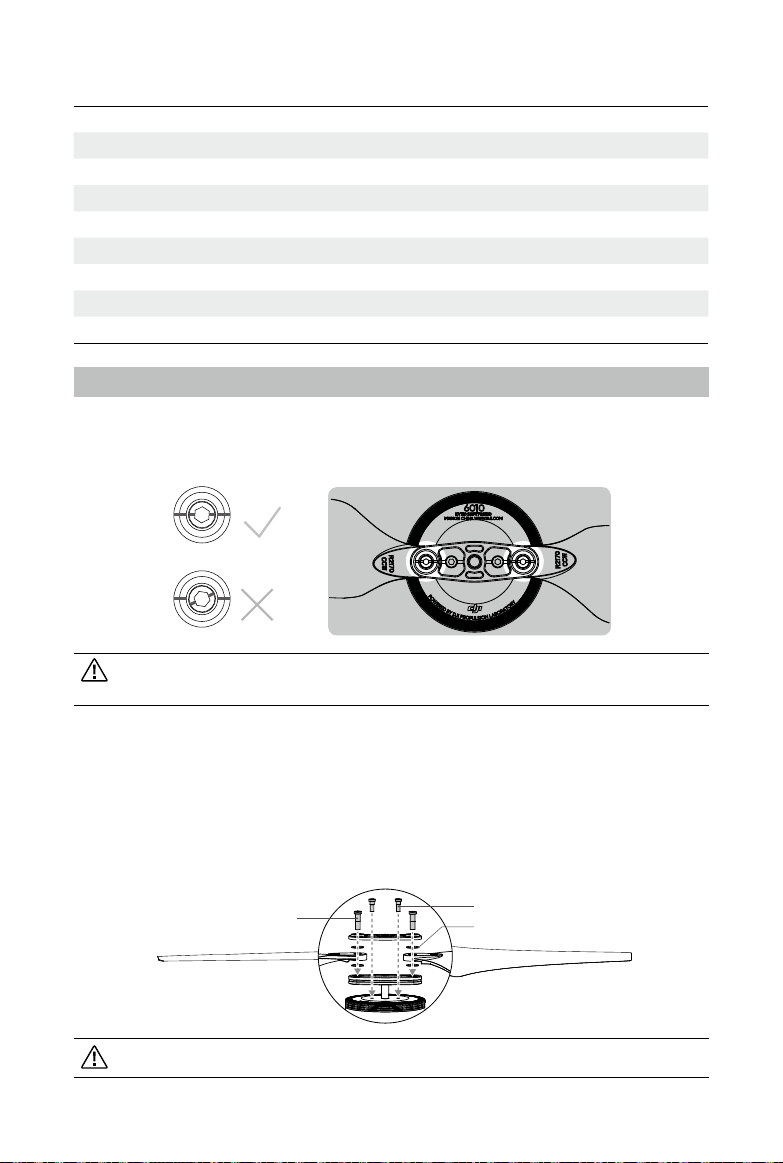
10. FAQ
How do I check if the propellers are secure and will not y off?
Make sure you check the marks on the screws and cover on the propeller before each ight. If the
propeller is loose, the marks will not line up, indicating that the screws should be tightened.
If the two propeller blade screws are swapped or other screws are used, the marks may
not be accurate.
How do I replace the propeller blades or propeller covers if they are damaged?
1) Prepare two propeller blade screws (M4×13.3 hex), two propeller cover screws (M3×9 hex), and
four propeller washers.
2) Apply threadlocker to the two screw holes on the motor and the propeller cover.
3) Assemble the propeller and tighten with two propeller blade screws (M4x13.3 hex) so that the
blades can fold smoothly. Mount the propeller onto the motor and use two propeller cover
screws (M3×9 hex) to secure the propeller.
Propeller Blade Screws
(M4×13.3 Hex)
Propeller Cover Screws (M3×9 Hex)
Propeller Washers
Ensure the screw is secured tightly for the threadlocker to be effective.
2016 DJI. All Rights Reserved.
10
©
Page 11

This content is subject to change.
Download the latest version from
http://www.dji.com/product/e2000
If you have any questions about this document, please contact DJI by
sending a message to
2016 DJI. All Rights Reserved.
©
DocSupport@dji.com
.
 Loading...