

Page 1

Dock Bundle
Installation and Setup Manual
2023.06v1.4
Page 2

This document is copyrighted by DJI with all rights reserved. Unless otherwise authorized by DJI,
you are not eligible to use or allow others to use the document or any part of the document by
reproducing, transferring, or selling the document. Users should only refer to this document and
the content thereof as instructions to operate DJI UAV. The document should not be used for other
purposes.
Searching for Keywords
Search for keywords such as Battery or Install to find a topic. If you are using Adobe
Acrobat Reader to read this document, press Ctrl+F on Windows or Command+F on Mac
to begin a search.
Navigating to a Topic
View a complete list of topics in the table of contents. Click on a topic to navigate to that
section.
Printing this Document
This document supports high resolution printing.
2023 DJI All Rights Reserved.
©
2
Page 3

Using this Manual
Legends
Important Hints and Tips
Read Before Use
DJITM provides users with the following documents.
1. Safety Guidelines
2. Quick Installation Guide
3. Installation and Setup Manual
4. User Manual
It is recommended to watch all the tutorial videos and read the Installation and Setup Manual to
understand the safety precautions and construction preparations before installation. Read the
Safety Guidelines to understand important safety matters and use the Quick Installation Guide to
complete on-site installation, configuration, and first flight test. Refer to the User Manual for more
information.
Video Tutorials
Go to the address below or scan the QR code to watch the tutorial videos, which demonstrate how
to use the product safely.
https://www.dji.com/dock/video
• The operating temperature of the dock is -35° to 50° C (-31° to 122° F) and the aircraft
is -20° to 40° C (-4° to 104° F).* It does not meet the standard operating temperature
for military-grade application (-55°to 125° C/-67° to 257° F), which is required to endure
greater environmental variability. Appropriately use the product for applications that
meet the operating temperature range requirements of that grade.
* When the temperature is below -20° C (-4° F), the aircraft cannot perform flight tasks, the dock cover and the driving rods
cannot be controlled automatically.
2023 DJI All Rights Reserved.
©
3
Page 4

Contents
Using this Manual 3
Legends 3
Read Before Use 3
Video Tutorials 3
Product Profile 7
Safety Precautions Before Installation 8
Construction Preparation 10
Environmental Survey 10
Environmental Requirements 10
Signal Quality Requirements 11
Using the Aircraft to Test 12
Ground Conditions Survey 14
Installation Location Requirements 14
Installation Method 15
Alternate Landing Site Requirements 18
Lightning Protection and Grounding Requirements 20
Lightning Protection System 20
Earth-termination System 21
Power Supply and Cable Requirements 22
Power Supply Requirements 22
Cable Requirements 22
Waterproof Distribution Box 24
Network Requirements 25
Ethernet Connection 25
Other 27
Protective Fence 27
Third-Party Security Camera 27
2023 DJI All Rights Reserved.
©
4
DJI Dock Installation and Connection 28
Getting Started 28
In the Box 28
User Prepared Tools and Items 29
Transportation and Temporary Storage 30
Page 5

Unpacking and Inspecting the Dock 32
Manually Opening the Dock Cover 32
Checking the Items Inside the Cover 32
Dock Installation 34
Confirming the Installation Orientation 34
Installing the Expansion Bolts 34
Mounting the Base Brackets 35
Accessories Installation 36
Mounting the Wind Speed Gauge Module 36
Connecting the Dock 37
A. Connecting the Earth Wire 37
B. Connecting the Power Cable 38
C. Connecting the Ethernet Cable 39
Sealing the Holes 39
Powering on the Dock 40
Before Powering On Checklist 40
Powering On and Checking 40
Preparing the Aircraft 42
Installing the Battery and Checking the Battery Level 42
Configuring the Dock Using DJI Pilot 2 43
Installation Checking 43
Configuring the Network of the Dock 44
Connecting the Dock and the Aircraft 44
Activation 45
Configuring the Cloud Service 45
Getting the Device Binding Code 45
Binding to DJI FlightHub 2 46
Calibrating the Dock Location 47
Setting the Alternative Landing Site 49
Completing the Configuration 50
Using Dock Onsite Debugging 51
Connecting the Remote Controller as Controller B 52
Closing the Electrical Cabinet Door 53
2023 DJI All Rights Reserved.
©
5
Page 6

Automatic Operation Test 54
Binding the Dock to a Project 54
Creating the Flight Route and Flight Plan 54
Performing the Flight Task 55
Alternate Landing Site Test 55
Before Leaving Checklist 56
Appendix 57
Status Indicators 57
Electrical Cabinet Indicators 57
Lower Compartment Components 58
Using Third-Party Payloads 59
Troubleshooting List 61
2023 DJI All Rights Reserved.
©
6
Page 7

Product Profile
MATRICETM 30 Series Dock Bundle is a fully automatic unattended operation platform. DJI Dock
is integrated with an ultra wide-angle camera, wind speed gauge, rain gauge, communication
antennas, RTK module, and UPS power supply. The dock weighs 105 kg and occupies less than
1 m2, which supports quick installation and configuration. With the M30 Series Dock Version
aircraft, DJI FlightHub 2 can be used to perform automated operations remotely.
Status Indicators
Internal Video
Transmission Antennas
Dock Cover Arms
Matrice 30 Series Dock
Version
2023 DJI All Rights Reserved.
©
7
Landing Pad Bolts
Wind Speed Gauge
Integrated Security
Camera
Camera Auxiliary Light
Rainfall Gauge
Dock Cover Propeller
Bumpers
Emergency Stop Button
Electrical Cabinet
Triangular Lock
Mounting Base Brackets
Page 8

Safety Precautions Before Installation
To ensure safety of people and the devices, follow the labels on the devices and the safety
precautions in the manual during installation, configuration, and maintenance.
• Installation, configuration, maintenance, troubleshooting, and repair of the dock must
be done by DJI authorized technicians in compliance with local regulations.
• The person who installs and maintains the dock must have undergone training to
understand the various safety precautions and be familiar with the correct operations.
They must also understand the various potential dangers during dock installation,
configuration, and maintenance and be familiar with the solution.
• Only those who hold a certificate issued by the local department can carry out abovesafety-voltage operation.
• Only those who hold a certificate issued by the local department can carry out
operations at heights above 2 m.
• Only those who hold a certificate issued by the local department can carry out
welding work.
• Make sure to perform the operation such as installation, configuration, and
maintenance in accordance with the steps in this manual.
• Make sure to wear protective equipment during installation, configuration, and
maintenance, such as a safety helmet, goggles, insulated gloves, and insulated shoes.
• Pay attention to personal safety when using any electrical tools.
• Wear a dust mask and goggles when drilling to prevent dust from entering the
respiratory tract or eyes.
• Make sure DJI Dock is properly grounded before use. When installing the dock,
connect the earth wire before other cables. When removing the dock, remove other
cables before the earth wire.
• DO NOT operate the dock without an earth wire installed.
• DO NOT damage the earth wire installed.
• DO NOT install, configure, or maintain the dock (including but not limited to moving
or installing the dock, connecting the cables, or performing operations at a height) in
severe weather such as thunderstorms, snowfall, or wind speeds is 12 m/s and above.
• DO NOT wear conductive objects (such as watches, rings, necklaces or other metals)
to install, configure or maintain the dock in order to avoid electric shocks or burns.
• Measure the voltage on the contact points of the conductor with a multimeter, make
sure there is no risk of electric shock before touching any conductor surfaces or
terminals (such as the terminals of the AC power input). The dock must be powered
off before installation.
• Make sure to turn off the main switch in the distribution box, then use a multimeter
or a voltage tester to conduct an electrical test at the end of the power cable before
installing or removing the power cable.
• Make sure the handle of the other tools such as a voltage tester is insulated to avoid
electric shocks.
2023 DJI All Rights Reserved.
©
8
Page 9

DJI MATRICE 30 SERIES Dock Bundle Installation and Setup Manual
• In the event of a fire, immediately evacuate the building or the dock installation
area and then call the fire department. DO NOT re-enter a burning building or dock
installation area under any circumstances.
• When carrying heavy objects, make sure to prepare to bear the weight to avoid
injures or being crushed by heavy objects.
• Pay attention to personal safety if the dock needs to be hoisted.
• Make sure to keep away from the dock when it is in operation, so as not to be injured
by moving mechanisms or rotating propellers.
2023 DJI All Rights Reserved.
©
9
Page 10

Construction Preparation
Make sure to read this chapter carefully, select a site for the dock according to the requirements,
and fill out the DJI Dock Site Survey Checklist. Failure to select a site according to the requirements
may lead to the dock malfunctioning, operational stability deterioration, shortening service life,
unsatisfactory effects and potential safety hazards, property losses, and casualties.
Environmental Survey
Environmental Requirements
• The installation site altitude should not be higher than 4000 m.
• The annual temperature of the installation site should be in the range of -35° to 50° C (-31° to
122° F), considering the dock operating temperature range is -35° to 50° C (-31° to 122° F)*,
and the aircraft flight operating temperature range in the dock is -20° to 50° C (-4° to 122° F).
Temperatures exceeding the range will cause the device to not work. To ensure operation
safety, the aircraft will not perform flight operations when the ambient temperature is lower
than -20°C (-4° F). At this time, the dock is in Standby mode, and operations can resume after
the temperature has risen.
• In order to ensure the normal operation of the dock and aircraft, choose a location with little
wind, sand or dust to install the dock. Make sure that the gust wind speed is not greater than
12 m/s and the airflow is stable when the aircraft takes off and lands.
• Make sure there are no obvious biological destructive factors such as rodent infestation and
termites at the installation site
• DO NOT install the dock near dangerous sources without permission, such as gas stations, oil
depots, and dangerous chemical warehouses.
• DO NOT install the dock in a site with flammable materials such as debris and catkins that are
easy to accumulate. RISK OF FIRE: Install the dock on a concrete or other non-combustible
surface only.
• DO NOT install the dock on moving objects, such as cars and boats.
• Avoid installing the dock in lightning strike areas.
• Avoid areas that are prone to water accumulation, servere erosion, landslides, heavy snow
accumulation, or other natural disasters.
• Avoid installing the dock in areas with chemical plants or septic tanks downwind to prevent
pollution and corrosion. It is recommended that the straight-line distance from the nearest
coastline is greater than 500 m.
• Avoid installing the dock directly under artificial lighting with reflective items on the ground.
Otherwise, it will interfere with the vision system of the aircraft, affecting its landing and flight
stability.
• It is recommended to install the dock at a distance of more than 200 m from sites with strong
electromagnetic wave interference, such as radar stations, mobile communication base
stations, and drone jamming equipment.
• It is recommended to install the dock at a distance from sites with iron ore and large steel
structures or buildings to avoid interference with the aircraft compass.
• It is recommended to install the dock at a distance from sites with strong vibration sources and
strong noise. Otherwise, it can cause interference to the dock environment sensors, and at the
same time easily lead to a decrease in the operating life of the whole machine.
• It is recommended to consider the future environmental factors of the installation site. Make
sure to avoid areas with large-scale construction plans or large environmental changes in the
2023 DJI All Rights Reserved.
©
10
Page 11

DJI MATRICE 30 SERIES Dock Bundle Installation and Setup Manual
future, including but not limited to the growth of weeds and trees (such as bamboo forests and
vines), new buildings, bridges, communication base stations, and high-voltage towers. If there is
any change, re-survey is required.
• It is recommended to consider whether the planned flight area is near or in a Restricted Zone.
Make sure to apply for a GEO Zone Unlocking License and import it to the aircraft during
installation and configuration.
* When the temperature is below -20° C (-4° F), the aircraft cannot perform flight tasks, the dock cover and the driving rods
cannot be controlled automatically.
• Historical weather data can be queried on meteorological websites.
• The dock can work in an environment with 93% relative humidity as it has a protection
rating of IP55.
• The normal transportation and storage temperature range is between -25° to 55° C (-13°
to 131° F). If the period does not exceed 24 hours, the dock can be transported or stored
at up to 70° C (158° F).
• When the dock is operating at full capacity, it has a sound power level of less than
74 dB(A) ± 3 dB(A) at a height of up to 0.5 m and a horizontal distance of 1 m from the
dock.
Signal Quality Requirements
It is recommended to install the dock in a place without obvious signal obstruction, such as in an
open area or on a roof top. Make sure there is no obvious signal obstruction within the range of
20° from the ground elevation angle to ensure the signal quality and stability of the built-in RTK
module in the dock.
If there is an obstacle, the minimum distance between the dock and the obstacle needs to meet
the following requirements:
Where:
is the minimum distance between the dock and the obstacle.
is the obstacle height (the height of the obstacle can be measured by operating the aircraft).
2023 DJI All Rights Reserved.
©
11
Page 12

DJI MATRICE 30 SERIES Dock Bundle Installation and Setup Manual
Make sure there is no obvious reflector in the sky and around the dock installation location, so
as to avoid impact on the normal operation of the aircraft video transmission system and GNSS
system. Reflectors include but are not limited to the glass curtain wall of the building, tinned
roofing, large solar panels on the roof, and metal billboards.
Using the Aircraft to Test
GNSS Signal Quality Survey
Use the M30 Series aircraft and DJI RC Plus remote controller (not included) to collect data for two
periods as required at the planned installation location. Follow the steps below:
1. Power on the aircraft and remote controller. Make sure the aircraft is linked to the remote
controller.
2. Run DJI PILOTTM 2 and tap on the home screen, select Dock Site Evaluation.
3. Follow the app instructions to create a new site evaluation task and conduct an environmental
survey.
4. Follow the app instructions to place the aircraft at the planned installation location. The app will
check the quality of the GNSS signal and complete the data analysis.
2023 DJI All Rights Reserved.
©
12
Page 13

DJI MATRICE 30 SERIES Dock Bundle Installation and Setup Manual
Performing a Flight Route Test
Perform flight routes around the planned installation location to evaluate operational capabilities,
such as video transmission signal strength, flight endurance, and RTK signal interference. Follow
the steps below:
1. Use the M30 series aircraft to create the flight route tasks via the app on the remote controller.
2. Take off from the planned installation location, and record the video transmission signal quality
and flight endurance during the flight.
• The flight distance is related to the actual operating area around the dock, so the survey
needs to be determined according to the user requirements.
• Make sure the planned installation location is not in a Restricted Zone or Altitude
Zone using DJI Pilot 2, otherwise the flight operation will be affected. If permission
to fly in a Restricted Zone is available, please visit https://fly-safe.dji.com/ or contact
flysafe@dji.com to unlock the zone.
2023 DJI All Rights Reserved.
©
13
Page 14

DJI MATRICE 30 SERIES Dock Bundle Installation and Setup Manual
>3 m
Ground Conditions Survey
After completing the ground condition survey, fill out the information such as the dock installation
location, installation method, installation orientation, and list of required materials. It is
recommended to mark the planned installation location of the dock and the Alternate Landing Site
using paint.
Installation Location Requirements
• Make sure to install the dock on the roof of a building that is structurally sound. DO NOT
install the dock in the corner of a roof in order to avoid the aircraft from accidentally
crashing.
• Try to avoid installing the dock on top of existing underground facilities.
• When installed on top of a building, make sure the RTK and video transmission signals
are not obstructed by any surrounding walls, structures, or other obstacles. Increase the
height of the installation base if necessary.
• The ground bearing capacity must not be less than 150 kg/m2.
• The installation area is recommended to be larger than 2.6 m × 3 m. Reserve at least 1 m at
the sides of the dock to allow the dock cover to open and the air conditioning unit to dissipate
heat. Reserve at least 0.85 m at the front and rear of the dock to allow for installation and
maintenance.
2023 DJI All Rights Reserved.
©
14
>1 m
Top View
>0.85 m
>0.85 m
>1 m
>2.6 m
Page 15

DJI MATRICE 30 SERIES Dock Bundle Installation and Setup Manual
1000 mm
Installation Method
Select one of the following methods to install the dock according to the actual situation, such as
establishing a concrete base, placing a steel frame base, or installing on the ground directly.
Using A Concrete Base
A. Applicable Places
Installing the dock on a concrete base can raise the height of the dock, avoiding ground
subsidence or risk of flooding so that the dock is properly fixed. Applicable places are as follows:
a. Ground without hardened concrete such as fields, woodlands, and grasslands.
b. Ground with hardened concrete but has large slopes or unevenness.
c. Ground with a loading capacity requirement, such as on top of buildings.
B. Concrete Base Requirements
• The concrete base size is recommended to be 1000 mm × 1000 mm × 100 mm. The specific
height of the concrete base can be adjusted according to the on-site flooding risk situation,
generally the minimum height should be no less than 100 mm.
• The concrete base is established using C25 concrete, with single-layer two-way reinforcement
and φ4 @ 150 mm mesh inside. Make sure the reinforcement is wrapped with a concrete
protection layer larger than 25 mm. C25 concrete mix ratio is as bellow:
Cement Water Sand Gravel
Weight 372 kg 175 kg 593 kg 1260 kg
Weight Ratio 1 0.47 1.59 3.39
• Reserve four mounting holes with M10 bolts pre-imbedded or mount four M10 expansion
bolts directly after the concrete hardens to facilitate subsequent installation of the dock.
• Preparing for lightning protection: The earth electrode above the ground should be made of
50 mm × 5 mm galvanized flat steel and is connected to the dock with a flexible copper core
cable. The part under the ground should be made of 50 mm × 50 mm × 5 mm galvanized angle
steel, and be inserted under the ground with a depth no less than 1.6 m. Refer to the Lightning
Protection and Grounding Requirements section for more information.
• Make sure to maintain the concrete base for at least 7 days after establishing it.
• Consider the convenience of the base establishing, the pipelines and cables around the
concrete base installed in the later stage can be exposed.
Concrete Base Surface
2023 DJI All Rights Reserved.
©
15
610 mm
610 mm
1000 mm
Mounting Holes for Dock
Top View
Page 16

DJI MATRICE 30 SERIES Dock Bundle Installation and Setup Manual
≥100 mm
1000 mm
150 mm
1000 mm
C. Base Establishing Steps
The base establishing steps vary according to the applicable site.
a. Applied to no hard ground
1. Tamp down the original soil to ensure a stable foundation.
2. Lay a 150mm thick crushed stone layer (sand and crushed stone ratio of 3:7, and crushed
stone particle size of 5-40 mm) on the top of the original soil layer, and then use the C25
concrete around the crushed stone layer to form the edge.
3. Lay the C25 concrete on the top of the crushed stone layer.
4. Smooth the C25 concrete surface, make sure the flatness is no more than ±4 mm and the
inclination is less than 5° from either side of the installation surface.
5. Install the earth-termination system for lightning protection.
Mounting Holes for Dock
C25 Concrete Base
Crushed Stone Layer
C25 Concrete Edge
Original Soil Layer
Sectional View
150 mm
b. Ground surface has hardened concrete but with large slopes or unevenness
1. Roughen the original concrete base surface.
2. Lay the C25 concrete.
3. Smooth the C25 concrete surface, make sure the flatness is not exceed ±4 mm, and the
inclination is less than 5°.
4. Install the earth-termination system for lightning protection.
Earth-termination
System
Mounting Holes for Dock
Concrete Base Surface
Original Concrete Base
2023 DJI All Rights Reserved.
©
16
C25 Concrete Base
Sectional View
≥100 mm
Earth-termination
System
Page 17

DJI MATRICE 30 SERIES Dock Bundle Installation and Setup Manual
1000 mm
1000 mm
c. Ground has loading capacity requirement
1. Make two C25 concrete mounds.
2. Smooth the C25 concrete surface, make sure the flatness is not exceed ±4 mm, and the
inclination is less than 5°.
3. Install the earth-termination system for lightning protection. The space between the two
mounds can be used for piping and wiring.
Concrete Base Surface
610 mm
Mounting Holes for Dock
450 mm
610 mm
Top View
Using A Steel Frame Base
• It is not suitable for no hard ground.
• When installing the dock on the top of the building, confirm in advance whether the roof
floor can be drilled. If not, it is recommended to use the steel frame properly fixed with
heavy objects (such as sandbags).
A. Applicable Places
If the installation location already has a concrete-hardened ground (such as a building roof), but
there may be risk of flooding, signal blocking, or land subsidence, use a steel frame base. The
construction period for this method is shorter as there is no maintenance stage.
B. Steel Frame Base Requirements
Customize a steel frame base (not provided) by following below requirements:
• Considering the tolerance in outdoor environment, it is recommended to use 40mm
• It is recommended that the base height of the dock is no less than 200 mm from the ground.
• The recommended measurements are shown as below:
17
galvanized square tube or 304 stainless steel square tube, and spray paint to avoid
corrosion.
Make sure the installation site is more than 100 mm from the highest recorded water level.
2023 DJI All Rights Reserved.
©
Page 18

DJI MATRICE 30 SERIES Dock Bundle Installation and Setup Manual
610 mm
610 mm
470 mm
158 mm
135°
Top View Side View
40 mm
8×Φ14 mm
20 mm
C. Installation Steps
1. Fix the steel frame base on the hardened ground with expansion bolts or heavy objects such
as sandbags.
2. Use M10 screws to install the dock on the steel frame base.
2
1
120 mm
40 mm
200 mm
Directly Installing on Ground
If the installation site has hardened-concrete ground and no risk of flooding or obvious obstacles
around, the dock can be directly installed on the ground using expansion bolts.
Alternate Landing Site Requirements
It is necessary to set up an alternate landing site near the dock. When there is an issue with the
dock or the aircraft cannot land due to external bad weather or equipment failure, the aircraft will
hover until low battery level occurs and then fies to the alternate landing site and lands.
• When choosing the alternate landing site, consider the clearance needed during the aircraft
landing process. Make sure there are no obstacles within a 1 m radius of the alternate landing
site.
• It is recommended to set the alternate landing site in an open area near the dock, which is at
the same height and has a straight-line distance of 5-50 m from the dock.
2023 DJI All Rights Reserved.
©
18
Page 19

DJI MATRICE 30 SERIES Dock Bundle Installation and Setup Manual
Third-Party
≥2 m
DJI Dock
5-50 m
Concrete BaseAlternate Landing Site
Security
Camera
• Pay attention to avoid personal injury when the aircraft is landing at the alternate landing
site.
• If the alternate landing site is set on the roof of the building, make sure not to set it in the
corner of a roof in order to avoid the aircraft from accidentally crashing.
2023 DJI All Rights Reserved.
©
19
Page 20

DJI MATRICE 30 SERIES Dock Bundle Installation and Setup Manual
Lightning Protection and Grounding Requirements
Lightning Protection System
The lightning protection system is mainly composed of an earth-termination system, a downconductor system, and an air-termination system such as a lightning rod, a lightning protection
belt, or a lightning protection net. When the air-termination system is stuck by a direct lightning
flash, the electrical current will quickly discharge to the earth through the down conductor system
and the earth-termination system.
The protected region of the air-termination system can be calculated using the rolling sphere
method. The rolling sphere method assumes that there exists an imaginary sphere of radius
above the ground surface. This imaginary sphere rolls on the grounded metallic objects that can
provide lightning shielding, such as lightning masts, shield wires, and substation fences. A device
remained within the imaginary sphere is said to be protected from a direct lightning flash.
Take the scenario with only one lightning rod standing on a flat surface for example, the maximum
safe distance that the dock can be placed from the lightning rod needs to meet the following
requirements:
Where:
is the maximum safe distance that the dock can be placed from the lightning rod.
is the height from the top of the dock to the ground when the dock cover is closed.
is the height of the lightning rod.
is the radius of the imaginary rolling sphere. This depends on the lightning density and the
standard given in the following table.
Protection Level Rolling Sphere Radius (m)
Type 1 30
Type 2 45
Type 3 60
If the dock is not under the protection of the nearest lightning rod, a designated lightning
protection system should be designed by a qualified professional.
2023 DJI All Rights Reserved.
©
20
Page 21

DJI MATRICE 30 SERIES Dock Bundle Installation and Setup Manual
Earth-termination System
The earth-termination system is an important part of the lightning protection system that can
discharge the electrical current to the earth. Use an earthing resistance meter to measure the
earthing resistance, and make sure that the earthing resistance for the dock is less than 10 Ω. It is
recommended to use an existing outdoor earth-termination system when installing the dock. Once
the distance between the earth-termination system and the dock is greater than 1 m, install the 40
mm × 4 mm flat steel within 1 m of the dock and connect it to the earth-earth electrode. If there
is no existing earth-termination system, additional earth electrodes and installation is required.
Follow the below descriptions for producing and installing the earth electrode.
A. Requirements for producing and installing the earth electrode
• It is recommended to produce the vertical earth electrode using hot-dip galvanized steel,
copper or copper-clad steel. The recommended length of the vertical earth electrode
is 1.5-2.5 m according to the soil quality and geographical conditions around the earth
electrode.
• The earth electrode number is determined by the size of the earth-electrode network and
the geographical environment. The distance between any two vertical earth electrodes
should not be less than 5 m. When using an earth-electrode network, make sure its four
corners use the vertical earth electrodes.
• If using angled steel, make sure one end is pointed, which can be made by using oblique
cutting.
• When installing the earth electrode under the ground, the depth should generally be
no less than 0.7 m (the distance between the upper end of the earth electrode and the
ground surface). In cold weather regions, the earth electrode should be installed below the
permafrost layer. In areas with thin gravel soil, the installation depth of the earth electrode
should be determined according to actual conditions.
• When using an earth resistance meter, make sure to operate it according to its
instructions, and to perform short-circuit zero calibration on the meter before performing
the measurement.
• If the earth resistance does not meet the requirements of the dock installation, it is
recommended to use multiple earth electrodes and apply a long-term resistancereducing liquid or use a special earthing rod.
• If the earth resistance is less than 10 Ω, the lightning protection system can be used for
the other earth-termination systems.
B. Earth Electrode Specifications
When the earth electrode is made of hot-dip galvanized steel, the length depends on the needs
of the installation, and the specifications are as shown below.
Earth Electrode Type Specifications
Steel Pipe Thickness no less than 3.5 mm
Angle Steel No less than 50 mm × 50 mm × 5 mm
Flat Steel No less than 40 mm × 4 mm
Round Steel Diameter no less than 10 mm
2023 DJI All Rights Reserved.
©
21
Page 22

DJI MATRICE 30 SERIES Dock Bundle Installation and Setup Manual
Power Supply and Cable Requirements
Power Supply Requirements
When using the dock, an external AC power supply needs to be connected to dock. The power
supply requirements are as shown below:
• The electrical connection should comply with local laws and regulations.
• Make sure to use a stable power supply without frequent power outages.
• Make sure the voltage and frequency of the AC power meets the dock operation requirements:
Parameters Specifications
Power Supply Single-Phase AC
Rated Input Voltage 100-240 VAC
Max. Input Voltage 264 VAC
Frequency 50/60 Hz
Power Max. 1500 W
• When supplying power to the dock, make sure to install a separate 2P 16A earth leakage circuit
breaker and a 40kA surge protection device in the user distribution box.
Cable Requirements
Make sure to lay the cables connecting the dock to the external power supply through protective
pipelines.
A. Cable Connection Suggestion
The recommended overall connection is shown below.
2023 DJI All Rights Reserved.
©
22
Third-Party Security Camera
Waterproof Distribution Box
Ethernet Cable Power Cable
PVC Pipes Under Ground
Concrete Base
If the user distribution box is more than 50 m
away from the dock, it is recommended to install
an additional outdoor waterproof distribution box
near the dock for convenient maintenance and
other equipment to draw power.
Protective Fence
Earth Electrode
Page 23

DJI MATRICE 30 SERIES Dock Bundle Installation and Setup Manual
B. Power Cable Requirements
• Make sure the ends of the power cables are crimped with pin terminals, which make it more
convenient when connecting the cables to the earth leakage circuit breaker.
• If the user distribution box is more than 50 m away from the dock, it is recommended to
install an additional outdoor waterproof distribution box near the dock for convenient
maintenance and other equipment to draw power.
• Make sure the power cable length and cross-sectional area meet the following requirements:
Power Cable Length Cross-sectional Area
<100 m three-core outdoor sheathed copper core cable of 13AWG (2.5 mm2)
100-200 m three-core outdoor sheathed copper core cable of 11AWG (4 mm2)
>200 m three-core outdoor sheathed copper core cable of 9AWG (6 mm2)
C. Protection Pipeline Laying Requirements
• Make sure the outdoor cables are laid with PVC pipes and are installed under the ground.
In the situation that the PVC pipes cannot be installed under the ground (such as on the top
of a building), it is recommended to use galvanized steel pipes fastened to the ground and
to make sure that the steel pipes are well grounded. The inner diameter of the PVC pipes
should be at least 1.5x the outer diameter of the cable, while taking the protective layer into
consideration.
• Make sure that there are no joints in the cables within the PVC pipes and that the joints of
the pipes are waterproofed, and the ends are well sealed with sealant.
• Make sure the power cable and the Ethernet cable are separated into different PVC pipes,
and the PVC pipes are not installed near the water pipes, heating pipes or gas pipes with a
distance of no less than 30 mm.
• Make sure that the PVC pipe that is laid through the bottom of the dock and has an outer
diameter of no more than 25 mm.
2023 DJI All Rights Reserved.
©
23
Page 24

DJI MATRICE 30 SERIES Dock Bundle Installation and Setup Manual
Waterproof Distribution Box
A. If necessary, make sure to install an outdoor waterproof distribution box that meet the
requirements as shown below:
• Make sure the waterproof distribution box is securely installed and that the bottom of it is at
least 500 mm above the ground to avoid flooding.
• Make sure the waterproof distribution box is installed on the side with the incoming power
cable that leads from the dock electrical cabinet for a secure cable connection and dock
configuration.
• Make sure the waterproof distribution box is more than 1 m away from the dock in order to
avoid affecting aircraft takeoff and landing.
• Make sure the lead-in and lead-out cables of the waterproof distribution box are protected
using PVC pipes that are installed under the ground, and that the joints between the pipe
and the distribution box are properly waterproofed and sealed with sealant.
• Make sure both the earth wires of the outlet in the waterproof distribution box and the lead-
out cables of the dock are properly connected to the waterproof distribution box and well
grounded.
B. The recommended electrical components in the waterproof distribution box are shown as
below:
Component Usage
Waterproof Distribution
Box
Ground Bus Bar Connects the earth wires of the lead-in cable, the socket, the lead-
C16 Earth Leakage Circuit
Breaker
C10 Earth Leakage Circuit
Breaker
DIN Rail Mount Socket of
10A
Contains various electrical components and provides waterproof
protection.
out cable, and the enclosure of the waterproof distribution box if
the waterproof distribution box is made of metal.
Connects the dock to supply power.
Connects the socket in the waterproof distribution box to supply
power.
Provides power for other devices such as the ethernet device,
hammer drill, laptop, mobile phone charger for convenient on-site
installation and configuration.
2023 DJI All Rights Reserved.
©
24
Page 25

DJI MATRICE 30 SERIES Dock Bundle Installation and Setup Manual
Network Requirements
When using the dock, it needs access to the Internet, connect to the internet by using an Ethernet
or a 4G wireless network.* The dock can also use the 4G wireless network as a backup to the
Ethernet connection. When both networks are connected, the Ethernet connection will be used in
priority.
* 4G network service is not available in some countries or regions. Please consult your local distributor for details.
Ethernet Connection
The requirements when connecting to the Ethernet are shown as below:
• It is recommended to use category 5e (Cat5e) or above twisted pair cable as the Ethernet cable.
• Make sure to use and install PVC pipes under the ground for outdoor cables. For situations
where PVC pipes cannot be installed under the ground, use galvanized steel pipes that are
fastened to the ground and ensure that the pipes are well grounded. Make sure to lay the
Ethernet cable during construction to facilitate quick dock installation.
• Make sure the power cable and the Ethernet cable are separated in different PVC pipes, and
that the PVC pipes are not installed near water pipes, heating pipes, or gas pipes.
• Select the appropriate connection method according to the distance between the user
computer room and the dock.
A. If the distance is less than 80 m:
Make sure to install a data and signal surge protector device to the lead-out cable from the user
computer room, so as to protect the network devices from being damaged by lightning strikes
and ensure stable data transmission. Follow the instructions as shown below for installation.
a. Use a Cat5e or above twisted pair cable and crimp the Cat5e pass through connectors at the
end.
b. Install a surge protector device in the grounded rail with reliable contact, and make sure that
the earth wire is properly connected to the ground.
c. Use the Ethernet cable, connect the IN end of the surge protector device to the dock and the
OUT end to the network devices such as a network switch and router. Make sure the IN and
OUT ends are properly connected, otherwise the surge protector device may be damaged
and the surge protection will not work.
Network Switch
4G Router or Network Provider
2023 DJI All Rights Reserved.
©
25
Ethernet Cable
User Computer Room
Ethernet Cable
OUT IN
Ethernet Cable
Length < 80 m
Surge Protection
Device
DJI Dock
Page 26

DJI MATRICE 30 SERIES Dock Bundle Installation and Setup Manual
B. If the distance is more than 80 m:
Use a fiber optic solution and install a fiber optic transceiver. Choose a fiber optic transceiver
that meets the transmission distance requirements, so as to avoid the mismatch between the
transmission distance and the transceiver, which may result in network instability or even loss
of connection.
Optical Fiber
Long-distance
Transmission
Ethernet Cable
Fiber Optic Transceiver DJI DockFiber Optic
Network Switch
Ethernet Cable
4G Router or
Network Provider
User Computer Room
Ethernet Cable
Transceiver
• It is recommended to use a Gigabit network with an upstream and downstream
bandwidth greater than 10 Mbps, to ensure a better user experience, it is recommended
to be greater than 40 Mbps. Use a laptop to measure the network speed using a speed
measurement website when the network port is connected.
2023 DJI All Rights Reserved.
©
26
Page 27

DJI MATRICE 30 SERIES Dock Bundle Installation and Setup Manual
>0.85 m
>0.85 m
>1 m
>1 m
>3 m
>2.6 m
Other
Protective Fence
Make sure to install a protective fence to ensure the safety of pedestrians and prevent theft of the
product so that unauthorized personnel cannot enter the area where the dock is installed.
Protective Fence Requirements
• Operators who enter the protective fence area need to undergo professional training
and fully understand the precautions and risks of various operations.
• Make sure that no flight plan is executed on DJI FlightHub 2 and that the aircraft has
landed inside the dock before entering the protective fence area when operating the
dock on site. After entering the area, make sure to press one of the emergency stop
buttons of the dock.
• According to laws and regulations, the protective fence dimensions must not be less than 3 m ×
2.6 m × 1.6 m (Length × width × height) and the fence panel spacing must be between 0.04-0.12 m.
• Make sure the protective fence is stable after installation, and that a door is installed for
personnel to enter for inspection and maintenance. Make sure the door is locked to prevent
unauthorized personnel from entering.
• Make sure that a warning sign that states Danger: Risk of Mechanical Equipment Injury is fixed
to the outside of the fence clearly.
• Make sure to use fiber-reinforced plastic or non-metallic fencing for minimal impact on the
video transmission signal and RTK signal.
• The protective fence needs to be purchased and installed by the user or service provider.
DJI does not provide this item.
1.065 m
0.04-0.12 m
Top View Side View
Third-Party Security Camera
An additional third-party security camera can be installed according to security monitoring
requirements.
0.04-0.12 m
• The dock provides a built-in ultra-wide-angle camera in the wind speed gauge module,
which is installed on the dock cover. Third-party security cameras need to be purchased
and installed by the user or service provider. DJI does not provide this item.
2023 DJI All Rights Reserved.
©
27
>1.6 m
Page 28

DJI Dock Installation and Connection
• Make sure to contact a DJI authorized service provider for installation. There may be
potential safety hazards if the product is installed by the user. Contact DJI Support for
more information on DJI authorized service providers.
Getting Started
In the Box
Check that all of the following items are included in the package.
Dock Body ×1 Aircraft* ×1
with microSD Card inserted
Triangular Key ×1
Expansion Bolt ×4
Sealant ×1
Wind Speed Gauge Module ×1
Manuals
In the Box
Safety Guidelines
Quick Installation
Guide
* The M30 Dock Version and M30T Dock Version are equipped with different cameras. Refer to the actual product
purchased. Aircraft batteries are packaged and delivered separately, and must be purchased additionally.
Accessories
USB-C Cable ×1 1671 Propeller (CCW) ×21671 Propeller (CW) ×2
Cable Ties Screws and Tools
PH0 2.5 mm
2023 DJI All Rights Reserved.
©
28
M1.4 M3 M2.5
T3 M42 mm 3 mm
Page 29

DJI MATRICE 30 SERIES Dock Bundle Installation and Setup Manual
User Prepared Tools and Items
Below are the tools and items used during installation and configuration, make sure to prepare
them in advance and ensure that the tools work properly.
Adjustable Wrench Steel Blade Measuring
Hammer DrillHex Key
Tape
5 mm
Claw Hammer Digital Level
Earthing Resistance
Multimeter
Meter
Voltage Tester Diagonal Cutting Pliers Wire Strippers Pin Terminal
Electrical TapePin Terminal Crimping
Pliers
Insulated Handle
Screwdriver
Cat5e Pass Through
Connector
Pallet Jack (optional) Electric Power Drill
(optional)
2023 DJI All Rights Reserved.
©
29
Cable Reel (optional)DJI RC Plus*LaptopCable Crimping Pliers
* The DJI RC Plus must be updated to the latest rmware
version. The remote controller needs to be activated
before rst use. Make sure the remote controller has
access to the internet during activation.
Page 30

DJI MATRICE 30 SERIES Dock Bundle Installation and Setup Manual
Transportation and Temporary Storage
• Make sure the dock is transported by a professionally trained operator. Operators should
read this manual carefully. If the dock is damaged due to failure to store, transport, install,
or use according to the instructions in this manual, it will not be covered by the warranty.
Carrying and Transporting the Dock
• When carrying and transporting the dock, make sure to prepare for load bearing to avoid
sprains or being crushed by heavy objects and to wear protective gloves to avoid injury.
When carrying and transporting the unpacked dock, move it carefully to avoid scratching the
surface. DO NOT impact or drop the dock to avoid damage.
A. Carrying and transporting the dock manually
When moving or lifting the dock, carefully lift the dock at the parts indicated in gray marked with
arrows in the diagram or hold the mounting base of the dock. DO NOT apply force on the dock
cover or other areas of the dock to avoid damage to the dock.
B. Carrying and transporting the dock using a pallet jack
Make sure the pallet jack is centered underneath the dock to prevent overturning. When
moving the dock, make sure there is a person at the side of the dock to keep it safe.
Lifting the Dock
• The operator who performs the lifting operation needs to undergo professional training
and can only work after obtaining the required qualification.
• Make sure the tools used for lifting the dock meet the standards and service life
requirements.
• DO NOT walk under the dock when it is lifted. Make sure to keep a safe distance from the
dock when it is moved to avoid injury from it from falling, rolling, or swinging.
It is recommended to use a crane cage to lift the unpacked dock (the crane cage needs to be
prepared by the lifting company and brought to the lifting site in advance). Otherwise, use the
rigging to lift the dock, make sure to select the correct lifting positions, connect the rigging
securely, and then try to lift it.
2023 DJI All Rights Reserved.
©
30
Page 31

DJI MATRICE 30 SERIES Dock Bundle Installation and Setup Manual
PE
N
L
Temporary Storage
If the dock is not to be used immediately, follow the requirements as shown below for
temporary storage:
• Store it in a dry, rainproof, and fireproof place with no corrosive materials around.
• Protect it from erosion and damage caused by wildlife.
• Make sure to check that the outer packaging of the dock is in good condition regularly. Make
sure to charge the backup battery for at least 6 hours every three months.
• If the dock is removed from being stored but not used for a period, place it in a waterproof bag
sealed with adhesive tape and then put it into its original packaging with a desiccant.
• DO NOT tilt or invert the dock or place items on top of the box when the dock is inside.
Backup Battery Charging Steps
• Only those who hold the certificates issued by the local department can carry out above
safety voltage operations.
• Make sure to pay attention to safety during operation in order to avoid an electric shock.
• Make sure that PE, N, and L cables are connected properly.
To charge the backup battery, follow the steps below.
1. Use the triangular key to open the electrical cabinet door of the dock.
2. Use a 3 mm hex key to loosen the four screws and remove the electrical cabinet plate.
3. Connect the three-core cable to the terminals of the AC power input port in the electrical
cabinet in sequence according to PE, N, and L.
4. Turn on the AC power switch (A) to power on the dock. Turn on the backup battery switch (B) to
charge the backup battery.
1
2
3
4
A B
• The backup battery cannot be charged when the temperature is higher than 40° C (104° F)
or lower than -20° C (-4° F).
2023 DJI All Rights Reserved.
©
31
Page 32

DJI MATRICE 30 SERIES Dock Bundle Installation and Setup Manual
开
ON
蓄电池
UPS
关
OFF
Unpacking and Inspecting the Dock
Manually Opening the Dock Cover
• DO NOT apply force or place heavy objects on the electrical cabinet door after opening.
• DO NOT apply force on the side of the dock covers in order to avoid any damage when
opening or closing.
• DO NOT apply force or place heavy objects on the top of the dock covers after opening.
1. Remove the box lid and then open the box, take out the manuals and the triangular key, and
then pull the sides of the box upwards to remove the box. Use the triangular key to open the
electrical cabinet door.
2. Turn on the backup battery switch to supply power to the dock. After the dock is powered
on, the buzzer sounds and the status indicators on the dock covers flash.
3. When opening the dock cover, press and hold the dock cover manual release button and
hold the connection between the cover arm and the cover shown in the diagram. Make sure to
open the right and left covers in turn. Make sure to control the dock cover descent speed
by holding the cover at all times to avoid personal injury or damage to the mechanism
caused by sudden movements.
3
开
ON
关
OFF
交流电源
蓄电池
后备保护器
电源防雷器
AC POWER
UPS
SCB
2
1
3
SPD
Connection Between the Cover Arm and the Cover
• If the dock does not power on after turning on the backup battery switch, the backup
battery power is low and needs to be charged. Refer to the Transportation and
Temporary Storage section for more information on the backup battery charging
steps.
Checking the Items Inside the Cover
1. Take out the packaging foam from inside the dock cover and remove the top cover of the foam.
2. Check the aircraft, accessory kit, expansion bolts (under the sealant box), and wind speed gauge
are included according to the In the Box list.
3. Press and hold the dock cover manual release button, hold the connection between the cover
arm and the cover, and then pull to close the left cover and then the right cover in turn.
2023 DJI All Rights Reserved.
©
32
Page 33

DJI MATRICE 30 SERIES Dock Bundle Installation and Setup Manual
4. Turn off the backup battery switch and close the electrical cabinet door.
• If there are any abnormalities, missing items, or inconsistencies, make sure to record onsite and contact your device carrier and device supplier.
• Make sure to pack the aircraft in its original packaging or to remove it from the dock for
separate transportation when transporting the unpacked dock.
2023 DJI All Rights Reserved.
©
33
Page 34
DJI MATRICE 30 SERIES Dock Bundle Installation and Setup Manual
Dock Installation
Confirming the Installation Orientation
Make sure to consider the below factors before installing the dock:
• If there is frequently ocurring strong wind in one direction at the installation site, make sure
to avoid the wind speed gauge module being installed downwind, so as to prevent the aircraft
from taking off and landing too close to the wind speed gauge module in a windy environment.
• Make sure the integrated security camera orientation is not facing direct sunlight, otherwise the
service life and camera view may be affected due to the environment.
• Make sure there are no obstacles blocking the dock covers.
• To avoid false detection when the aircraft lands, make sure that there are no light-colored
objects similar to the shapes or visual identification marks on the landing pad within 5 m of the
dock, such as white rectangles, white triangles, and H patterns.
• If multiple docks are installed at the same location, the distance between each dock should be
at least 5 m.
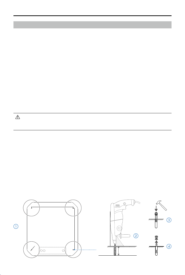
Installing the Expansion Bolts
• Wear a dust mask and goggles when drilling holes to prevent dust from entering the
throat or falling into the eyes. Pay attention to personal safety when using any electric
tools.
The following installation instructions use a concrete base as an example.
1. Place the box lid with the installation hole signs facing upward at the location where the dock is
installed and adjust the orientation and position accordingly.
2. Align the hammer drill (drill diameter Ф14 mm) with the installation hole signs, keep the
hammer drill vertical to the ground and drill four installation holes with a depth of 55-60 mm.
Remove the box lid after drilling, make sure to clean up the surrounding debris to avoid it from
falling into the hole.
3. Slightly tighten the nuts of the four expansion bolts provided, put them vertically into the
installation holes, and tap the bolts with a claw hammer until the expansion tubes are
submerged into the installation holes.
4. After pre-tightening the screw bolt until it does not rotate, unscrew the nut, spring washer, and
flat washer.
2023 DJI All Rights Reserved.
©
34
Ø14*4
610 mm
穿线孔
CABLE HOLE
610 mm
Ф14 mm
90°
55-60 mm
Page 35

DJI MATRICE 30 SERIES Dock Bundle Installation and Setup Manual
Mounting the Base Brackets
• DO NOT put hands under the mounting base bracket during adjustment to avoid injury
if it is difficult to align the expansion bolt with the hole of the mounting base bracket, and
the position of the dock needs to be adjusted.
1. Use an adjustable wrench to remove the four bolts from the mounting base brackets.
2. Carefully lift the dock at the parts indicated in gray marked with arrows in the diagram. Move
the dock to the installation location, align the four mounting base bracket holes with the
expansion bolts, and then put it down slowly. It is recommended that at least four people carry
it. Read the Transportation and Temporary Storage section for more information on how to
carry and lift the dock.
3. Place the digital level on the top of the dock for measurement. If the inclination exceeds 5°, use
metal gaskets or other materials to fill the base bracket that needs to be raised.
4. Install the flat washer, spring washer, and nut of the expansion bolt in sequence, and tighten
the nut with an adjustable wrench.
2023 DJI All Rights Reserved.
©
35
Page 36

DJI MATRICE 30 SERIES Dock Bundle Installation and Setup Manual
Accessories Installation
• Make sure that the status indicators on the dock covers are off, to ensure that the dock is
powered off before mounting and connecting.
Mounting the Wind Speed Gauge Module
1. Remove the cover of the wind speed gauge module mount on the top of the dock cover.
2. Use a 2.5 mm hex key to remove the two screws on the wind speed gauge module bottom and
store them properly, then connect the signal cable of the dock to the port on the wind speed
gauge module bottom, and tighten the screws.
2. Align and insert the wind speed gauge module into the mount on the dock cover. Make sure the
ultra-wide-angle camera of the wind speed gauge module is facing the landing pad.
3. Rotate the wind speed gauge module lock sleeve in a clockwise direction until hearing a "click"
to complete the installation. Make sure that the installation mark on the wind speed gauge
module locking sleeve is aligned with the line on the wind speed gauge module.
1
3
2
FIX
2023 DJI All Rights Reserved.
©
36
Page 37

DJI MATRICE 30 SERIES Dock Bundle Installation and Setup Manual
Connecting the Dock
The electrical connection is to connect the external cables to the electrical cabinet for dock
grounding, power supply and Ethernet connection.
1. After opening the door of the electrical cabinet, use a 3 mm hex key to loosen the four screws
and remove the electrical cabinet plate.
2. Make sure to lead the pre-embedded connecting cables through the PVC or corrugated pipes
and then pass them through the cable holes at the bottom of the electrical cabinet. Make sure
that the external pipe joints are waterproofed.
3. Connect the earth wire, power cable, and Ethernet cable to the electrical cabinet in sequence
according to the following requirements.
1
• Make sure to use the low temperature resistant cables when the dock is installed in low
temperature areas.
• Make sure the power cable length and cross-sectional area meet the requirements as
described in the Power Supply and Cable Requirements section.
2
A. To Earth Wire
B. To Power Cable
C. To Ethernet Cable
A. Connecting the Earth Wire
• The dock must be properly grounded by following the below requirements.
• Check that the design and construction of the earth-termination system meet the
requirements before installation. Make sure that the earthing resistance between the
earth and the earth-termination system connected to the dock is less than 10 Ω by using
an earthing resistance meter for measurement.
1. Make sure to use 16mm2 diameter wire for an the earth wire when grounding.* Make sure that
the earth wire is not longer than 1 m and both ends are crimped with terminals. Keep the earth
wire as short and straight as possible, and avoid coiling or intertwining with signal cables.
2. Lock one end of the earth wire to the terminal of the ground bus bar inside the electrical cabinet
using a 5 mm hex key. Pass another end through the cable hole, connect to the lead-out pole of
the earth electrode, and tighten it with a screw.
* The color of the earth wire varies by country and region.
2023 DJI All Rights Reserved.
©
37
Page 38

DJI MATRICE 30 SERIES Dock Bundle Installation and Setup Manual
PE
N
L
PE
N
L
A
B. Connecting the Power Cable
• Only those who hold the certificates issued by the local department can carry out the
above-safety-voltage operation.
• Before the operation, make sure to turn off the main switch in the distribution box and
hang a sign to prohibit turning on the switch.
• Use a multimeter or a voltage tester to measure the electricity at the end of the power
cable. DO NOT operate with an electrical current.
1. Lead the pre-embedded power cable through the cable hole at the bottom of the electrical
cabinet and reserve the proper length for connection.
2. Use the diagonal cutting pliers to remove about 70 mm of the cable insulation layer and then
use the wire strippers to remove about 8 mm of the wire insulation layer. Insert the three wire
ends into the pin terminals and crimp them with the cable crimping pliers. Wrap and cover
the connection of the cable insulation layer and the wire insulation layer with electrical tape to
about 10 mm in length.
3. Insert the PE (protective earth wire), N (neutral wire), L (live wire) terminals* of the power cable
into the AC power input port in sequence and tighten them using a flathead screwdriver with an
insulated handle. Finally tidy and fix the power cable using cable ties.
* The color of PE, N and L wires vary by country and region. Make sure the three wires are properly and securely
connected.
10
70
8
PE N L
10
70
8
B
PE N
• Be careful not to damage the wire insulation layer when stripping the cable insulation layer.
2023 DJI All Rights Reserved.
©
38
L
Unit: mm
Page 39

DJI MATRICE 30 SERIES Dock Bundle Installation and Setup Manual
PE
N
L
C. Connecting the Ethernet Cable
• Make sure to install a data and signal surge protector device in the user computer room
and that it is properly grounded. Refer to the Network Requirements section for more
information.
1. Lead the pre-embedded Ethernet cable through the cable hole at the bottom of the electrical
cabinet and reserve the proper length for connection.
2. Use category 5e or above shielded twisted pair cable and crimp it to the category 5e pass
through connectors by following the T568B wiring standard. Make sure that the shielded
metal mesh of the cable is connected to the metal shell of the pass through connector, the
PVC surface of the cable is effectively inserted into the connector, and that the inner wire is not
exposed.
3. Insert one end of the Ethernet cable to the Ethernet port, and then tidy and fix the cable with
cable ties. Make sure another end is properly and securely connected to the device in the user
computer room.
C
• Make sure the network is able to access Internet with an upstream and downstream
bandwidth greater than 10 Mbps.
Sealing the Holes
Use the provided sealant to seal the holes at the bottom of the electrical cabinet where the cables
have passed through. Make sure that the sealant completely covers the holes and securely seals.
2023 DJI All Rights Reserved.
©
39
Page 40

DJI MATRICE 30 SERIES Dock Bundle Installation and Setup Manual
N
L
Powering on the Dock
Before Powering On Checklist
Checklist Description
Earth Wire The two ends of the earth wire are properly connected, and the screws are
securely tightened.
Power Cable The protective earth wire, neutral wire, and live wire are securely connected
and the wire sequence is correct.
The power cable connectors and the terminals are securely tightened.
The cables are neatly tied.
Ethernet Cable Wire sequence in the pass through connector is correct by following the
T568B wiring standard.
The PVC surface of the cable is eectively inserted into the connector, and
the inner wire is not exposed.
The pass through connectors are securely inserted in the network ports.
The Dock The dock is properly installed with a tilt angle of less than 5°.
The inside of the electrical cabinet is clean and tidy, without dust, dirt, or
items left inside.
Pull out the emergency stop buttons on both sides of the dock and make
sure they are released.
The
Surrounding
Environment
The area around the dock has been cleared of packaging materials such as
cartons, foam, plastic, and cable ties.
No obstacles block the dock covers when they are opened.
Powering On and Checking
1. After completing the before powering on checklist, turn on the upstream main switch in the
user distribution box and use a multimeter to measure the dock's AC power input at the
terminals N (using the black test lead) and L (using the red test lead) to ensure that the voltage
meets the requirements.
2. Turn on the surge protector circuit breaker (A), AC power switch (B), and backup battery switch (C)
in the electrical cabinet in sequence.
3. Within 30 seconds, the electrical cabinet should display as follows. Otherwise, troubleshooting
is to be performed.
A B C
2023 DJI All Rights Reserved.
©
40
Page 41

DJI MATRICE 30 SERIES Dock Bundle Installation and Setup Manual
Electrical Cabinet Indicators Normal States Description
Power Indicator Solid red AC power supply is normal.
Backup Battery Indicator
Wired Network Indicator Blinks green quickly Ethernet is connected and has data transfer with the dock.
4G Network Indicator Blinks green quickly 4G network is connected and has data transfer with the dock.
Solid blue Backup battery is full or is supplying power to the dock.
Blinks blue slowly Backup battery is charging.
• The surge protection device needs to be repaired or replaced if the indicator turns red or
it unexpectedly turns off.
2023 DJI All Rights Reserved.
©
41
Page 42

DJI MATRICE 30 SERIES Dock Bundle Installation and Setup Manual
Preparing the Aircraft
Preparing the Aircraft
1. Make sure that the propellers are securely mounted and not damaged or deformed, there are
no foreign objects in or on the motors or propellers, the aircraft arms are unfolded, and that
the frame arm folding buttons are popped out into the locked position.
2. Make sure the lenses of the vision systems, gimbal cameras, FPV camera, glass of the infrared
sensors, and auxiliary lights are clean and not blocked in any way and that the protective
stickers are removed.
3. Make sure the waterproof rubber port covers are properly and securely sealed in place.
4. Make sure the gimbal camera is facing forward.
Installing the Battery and Checking the Battery Level
Insert two TB30 batteries. Make sure the battery release toggles are in the same position as shown
in the diagram.
Press the battery level button once to check the current battery level.
High
Low
2023 DJI All Rights Reserved.
©
42
Page 43
Configuring the Dock Using DJI Pilot 2
• DO NOT move the configured dock. If the site changes, the dock needs to be reconfigured.
• Make sure to keep a safe distance from the dock cover when opening using DJI Pilot 2 in
order to avoid injury. Press any of the emergency stop buttons on the dock to stop the
dock covers from opening, if necessary.
• It is recommended to close the dock cover in the app or FlightHub 2 when the aircraft is
placed in the dock. Make sure to move the two blades of each motor to be at 90° with
each other in order to avoid breaking the propellers when manually closing the dock
cover.
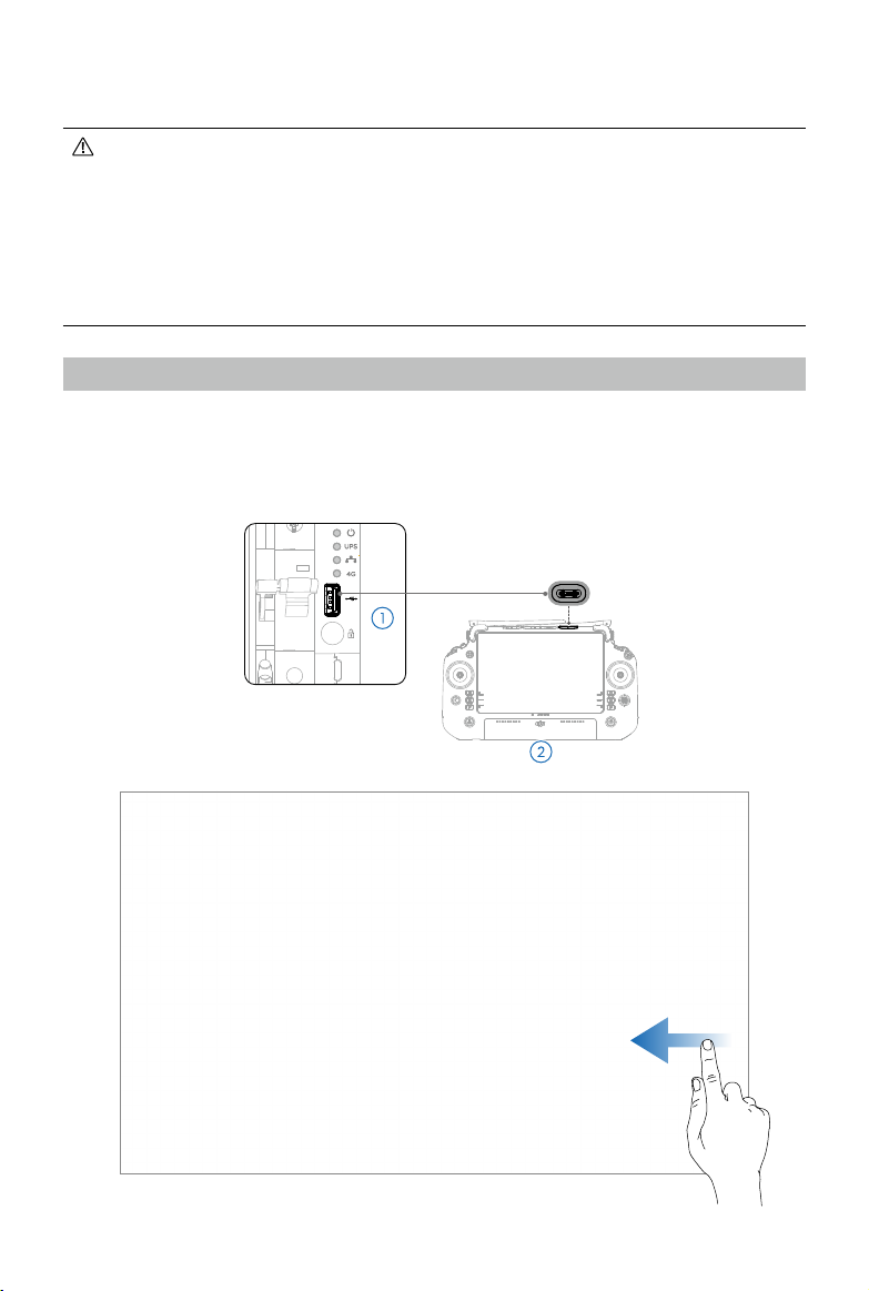
Installation Checking
1. Use the USB-C cable included to connect the USB-C port of the remote controller to the USB-A
port of the dock electrical cabinet.
2. Power on the remote controller, run DJI Pilot 2, and follow the installation steps prompted.
Check each step to ensure correct installation and connection.
USB-C
Pilot 2 App
2023 DJI All Rights Reserved.
©
43
Page 44

DJI MATRICE 30 SERIES Dock Bundle Installation and Setup Manual
Configuring the Network of the Dock
Perform the network configuration according to the prompts in the app and the actual network
conditions.
Connecting the Dock and the Aircraft
The aircraft and the dock have been linked before delivery when they are purchased as a combo.
1. If the aircraft cannot be powered on due to low battery level, place the aircraft on the landing
pad with the aircraft nose pointing to the arrow printed on the landing pad, and then tap the
Charge button in the app to charge the aircraft.
2. Tap the Link button in the app to connect the dock and the aircraft by following the onscreen
instructions in the app. During the linking process, the status indicator on the dock covers will
blink blue slowly, and the buzzer emits a beeping sound.
2023 DJI All Rights Reserved.
©
44
Page 45

DJI MATRICE 30 SERIES Dock Bundle Installation and Setup Manual
Activation
Make sure the aircraft is linked to the dock. Activate the dock and the aircraft by following the
instructions in the app.
• The aircraft and the dock require activation before first time use. An internet connection
is required for the remote controller during activation.
Configuring the Cloud Service
The automatic operation of the dock bundle needs to be performed using the cloud service. Bind
the dock and aircraft to DJI FlightHub 2 using DJI Pilot 2.
Getting the Device Binding Code
1. Use a computer to visit https://fh.dji.com, and log in to DJI FlightHub 2 using a DJI account. Click
to create an organization, fill in the organization information, and click the created organization
name to enter the organization page.
2. Click Devices > Dock > Device Binding as shown in the diagram to obtain the organization ID
and device binding code.
2023 DJI All Rights Reserved.
©
45
Page 46

DJI MATRICE 30 SERIES Dock Bundle Installation and Setup Manual
Binding to DJI FlightHub 2
Fill in the information in DJI Pilot 2 with the obtained organization ID and device binding code to
bind the dock and aircraft to DJI FlightHub 2.
• They can also be bound to a third-party cloud platform according to actual needs. Click
the third-party cloud service in the cloud service drop-down list, and follow the prompts
in the app to bind.
2023 DJI All Rights Reserved.
©
46
Page 47

DJI MATRICE 30 SERIES Dock Bundle Installation and Setup Manual
Calibrating the Dock Location
Make sure that the built-in RTK module of the dock can obtain accurate coordinates and calibrate
the dock location to obtain an accurate absolute position.
1. Before calibration, make sure that the dock covers are opened and the driving rods are pulled
back. Tap Open Dock button in the app to open the dock covers and pull the driving rods back.
'Remove any objects from the Dock's landing pad. Make sure the built-in RTK antenna area on
the landing pad is not covered. During calibration, stay away from the dock to avoid the RTK
antenna being blocked.
2. Custom network RTK calibration and manual calibration are available. Custom network RTK
calibration is recommended to obtain better accuracy and simplify the operation. Make sure
the remote controller is connected to the Internet during calibration.
3. Wait until the app displays the calibration results as converged and fixed.
2023 DJI All Rights Reserved.
©
47
Page 48

DJI MATRICE 30 SERIES Dock Bundle Installation and Setup Manual
• The dock location calibration data is valid for a period. There is no need to calibrate it
when the dock is restarted. However, re-calibration is required once the dock is moved.
• After the dock location is calibrated, the RTK positioning data of the aircraft may suddenly
change. This is normal.
• To ensure the accuracy of flight operations, make sure that the RTK signal source used
during flight is consistent with the RTK signal source used during the dock location
calibration when importing flight routes using DJI FlightHub 2. Otherwise, the actual flight
trajectory of the aircraft may deviate from the planned flight route, which may lead to
unsatisfactory operation results or even cause the aircraft to crash.
• When the dock is connecting to the remote controller and the dock covers are opened
using DJI Pilot 2, make sure to keep a safe distance from the dock cover movement
mechanism to avoid injury. Press any of the emergency stop buttons on the dock to stop
the dock cover moving, if necessary.
2023 DJI All Rights Reserved.
©
48
Page 49

DJI MATRICE 30 SERIES Dock Bundle Installation and Setup Manual
Setting the Alternative Landing Site
When the dock or the aircraft fails or is affected by external bad weather, the aircraft cannot land
at the dock, however it can fly to and land at an alternate landing site. Follow the prompts in the
app to set an alternate landing site, pay attention to the following requirements:
1. Tap Set Alternate Landing Site in the app and follow the prompts to operate. Make sure the
alternate landing site is not too far away, otherwise it will affect the flight operation endurance.
2. Set a reasonable Alternate Route Altitude to ensure that there are no obstacles when the
aircraft flies from the dock to the alternate landing site to avoid collisions.
2023 DJI All Rights Reserved.
©
49
Page 50

DJI MATRICE 30 SERIES Dock Bundle Installation and Setup Manual
Completing the Configuration
Make sure the driving rods on the landing pad are pulled back, the aircraft heading is consistent
with the arrow mark on the landing pad, and the aircraft is placed on the landing pad, move the
two blades for each motor to be at 90° with each other as shown in the diagram to complete the
configuration.
Aircraft Heading
2023 DJI All Rights Reserved.
©
50
Page 51

DJI MATRICE 30 SERIES Dock Bundle Installation and Setup Manual
Using Dock Onsite Debugging
Dock Onsite Debugging in DJI Pilot 2 provides the dock status, the aircraft status, and operations
such as linking aircraft, charging aircraft, and controlling dock and driving rods.
1
4
5
6
2
3
7
1. Dock Status
Displays information such as the running time, flights, air conditioner status, input voltage,
inside temperature or humidity, outside temperature, rainfall scale, and wind speed. Tap
Linking to enter the aircraft and dock linking page.
2. Aircraft Status
Displays information such as aircraft is inside dock or not, battery temperature, and battery
level.
2023 DJI All Rights Reserved.
©
51
Page 52

DJI MATRICE 30 SERIES Dock Bundle Installation and Setup Manual
3. Control Console
Supports the control of the dock covers, driving rods, dock sound and light alarms, aircraft
battery charging status, aircraft powering on and off.
4. Flight Restriction Information
Imports the applied GEO Zone Unlocking License in the app to ensure smooth subsequent
operations.
5. Maintenance Service
Provides historical flight data to help users determine if maintenance is required.
6. DJI Care Enterprise
Relevant information can be viewed if the device is bound to DJI Care.
7. Reconfiguring the Dock
Tap to re-configure the dock.
• Make sure the dock is properly functioning before disconnecting the USB-C cable.
Connecting the Remote Controller as Controller B
To ensure the safety of the flight test for the dock, the remote controller can be used to take
control of the aircraft manually during flight after connecting to the aircraft as controller B.
1. After disconnecting the USB-C cable, restart DJI Pilot 2, tap Controller A on the home screen, and
select to switch to Controller B.
2. Power on the aircraft, press and hold the power button on the aircraft for at least five seconds,
and wait for the remote controller to successfully link with the aircraft.
5s
• Go to the camera view in DJI Pilot 2, tap to set the parameters for the flight
controller, sensing system, remote controller, and battery.
2023 DJI All Rights Reserved.
©
52
Page 53

DJI MATRICE 30 SERIES Dock Bundle Installation and Setup Manual
开
ON
后备保护器
SCB
电源防雷器
SPD
交流电源
AC POWER
蓄电池
UPS
关
OFF
Closing the Electrical Cabinet Door
Install the electrical cabinet plate onto the electrical cabinet panel with four screws. Close and lock
the electrical cabinet door.
2023 DJI All Rights Reserved.
©
53
Page 54

Automatic Operation Test
To ensure that the dock and aircraft are properly functioning, make sure to create a flight route
and plan a flight task in DJI FlightHub 2, and then launch the flight task to allow the dock to perform
the automatic operation test after completing the dock configuration in the app.
Binding the Dock to a Project
1. Use a computer to visit https://fh.dji.com, and log in to DJI FlightHub 2 using a DJI account.
2. Click Project > + in the project list, and then fill in the information to create a project.
3. Click Devices > Dock > Actions > Edit as shown in the diagram and add the dock to the
specified project in the drop-down box of the project.
• Click Members to add members and fill in the member account (DJI account),
organization names, and roles.
Creating the Flight Route and Flight Plan
• When planning a flight route in DJI
FlightHub 2, make sure to check the
flight altitude. Fly with caution.
1. Click Project > > > + on the flight route
list to create a flight route, select M30 Series
from the aircraft and payload list, and then
click OK.
2. Click to add waypoints and waypoint
actions, set flight route parameters in the
flight route editor, and then save and exit.
3. Click > Create Plan to display the diagram
shown. Fill in the flight plan name, select the
execution flight route and execution dock,
set the Plan Timer to Immediate, set the
RTH altitude relative to the dock, and the
signal lost action during the flight, and click
OK to complete the new flight plan.
2023 DJI All Rights Reserved.
©
54
Page 55

DJI MATRICE 30 SERIES Dock Bundle Installation and Setup Manual
Performing the Flight Task
• During the flight test, make sure the remote controller is connected to the aircraft as
Controller B.
1. After starting to perform the flight task, the dock covers are opened, the driving rods are pulled
back, and the aircraft takes off. The dock covers will be closed after the aircraft takes off.
2. Click Project > Team to display the diagram shown, view the flight task status and warning
information of the dock and aircraft in the left column. Click to open the device status
window, and view the real-time status information and liveview of the dock and aircraft. On the
map, view the planned route (in green) and the flight trajectory (in blue) of the aircraft.
3. After completing the flight, the aircraft flies above the dock, and the dock will automatically
open the covers to allow the aircraft to land. After the aircraft lands, the dock pushes the driving
rods forward into place and closes the covers.
4. After the flight task is complete, click to open the plan library, view the number of media files
in the media upload bar, and click the corresponding number to open the media library to view
the media files captured during flight.
• During the flight test, once the remote controller takes control of the aircraft, DO NOT
update the Home Point in the app, otherwise the aircraft will not be able to return to the
dock.
• Refer to the Dock Bundle User Manual and the DJI FlightHub 2 User Guide for more
infomation.
Alternate Landing Site Test
During the flight task, press any emergency stop button to test if the aircraft can fly to the alternate
landing site. Once the emergency stop button is pressed, after completing the flight task, the
aircraft will return to the top of the dock, and then fly to the alternate landing site at the alternate
route altitude. During the flight test, make sure the remote controller is connected to the aircraft as
Controller B.
2023 DJI All Rights Reserved.
©
55
Page 56
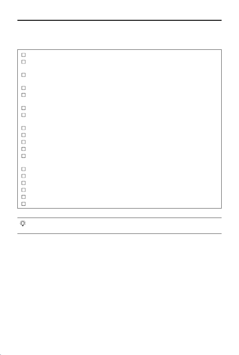
DJI MATRICE 30 SERIES Dock Bundle Installation and Setup Manual
Before Leaving Checklist
Before leaving the site, be sure to check the following items.
The HMS of DJI FlightHub 2 has no abnormal alarm.
The wind speed gauge module is mounted securely and the security camera orientation is
correct.
Check the wind speed gauge data displayed in DJI FlightHub 2 by rotating the wind speed
gauge.
The rain gauge surface is clear of dirt or foreign objects.
Check the rain gauge data displayed in DJI FlightHub 2 by gently tapping the top of the rain
gauge.
The sealant completely covers the holes and seals the cables completely.
The surge protector circuit breaker, AC power switch, and backup battery switch in the
electrical cabinet are turned on.
The electrical cabinet plate has been installed.
The landing pad surface is clear of dirt or foreign objects.
The aircraft is correctly placed on the landing pad.
The waterproof rubber port covers are correctly in place and securely sealed.
The lenses of the vision systems, gimbal cameras, FPV camera, glass of the infrared sensors,
auxiliary lights are clean and that the protective stickers are removed.
The driving rods on the landing pad are pushed forward into place.
The dock covers are closed.
The dock cover surface is clear of dirt or foreign objects.
The electrical cabinet door is closed and locked.
The aircraft alternate landing site test has been completed.
Check whether the GEO Zone Unlocking License has been imported in DJI Pilot 2 (if any).
• If the installed dock is left outside for an extended period, make sure to remove the
aircraft from the dock and store it separately, and to charge the backup battery regularly.
2023 DJI All Rights Reserved.
©
56
Page 57

Appendix
Status Indicators
The status indicators on the dock covers are used to display the current dock working status.
Normal States
Blinks white The dock is working normally and the aircraft is ready to take o.
—
Warning States
—
Blinks blue
Blinks green
Solid blue
Blinks red
Blinks red and
yellow alternately
Solid Red The dock is malfunctioning.
Electrical Cabinet Indicators
Electrical cabinet indicators are used to display the current status of dock power input, backup
battery, Ethernet and wireless network connection.
The dock and the aircraft are linking, and the buzzer emits a
short beep.
The aircraft has taken o from the dock and is performing a ight
task.
The dock is updating or debugging (including remote debugging
and on-site debugging).
The dock covers are moving or the aircraft is taking o or landing,
and the buzzer emits a long beep.
Any of the emergency stop buttons on the dock is pressed.
Status Indicator
Power Indicator
Backup Battery
Indicator
Wired Network
Indicator
4G Network
Indicator
2023 DJI All Rights Reserved.
©
57
Power Indicator
Backup Battery Indicator
Status Description
Solid Red AC power supply is normal.
—
Off No AC power supply.
Solid blue
—
Blinks blue slowly Backup battery is charging.
Blinks blue quickly Backup battery level is low.
Off
Blinks green quickly
Off Ethernet is disconnected.
Blinks green quickly
Off 4G network is disconnected.
Wired Network Indicator
4G Network Indicator
Backup battery is fully charged or is
supplying power to the dock.
Backup battery is not installed or the
backup battery switch is off.
Ethernet is connected and has data
transmission.
4G network is connected and has data
transmission.
Page 58

DJI MATRICE 30 SERIES Dock Bundle Installation and Setup Manual
Lower Compartment Components
Use the triangular key to loosen the two bolts on the landing pad, hold the landing pad edge to lift
it up. Make sure the support prop rod is holding the landing pad in a stable position.
Backup Battery
Air Conditioning Module
Return Vent
• Before closing the landing pad, make sure to hold the landing pad and push it back
slightly to release the support prop rod, and then slowly lower it.
Air Conditioning Controller
Supply Vent
Main Controller Module
Power Supply Module
Dock Cover Motor
Motor Driver
2023 DJI All Rights Reserved.
©
58
Page 59

DJI MATRICE 30 SERIES Dock Bundle Installation and Setup Manual
Using Third-Party Payloads
The aircraft provides a PSDK port for connecting a third-party payload and the dock reserves a
space inside the cover for storing the third-party payload, which facilitates the expansion of the
aircraft operating capabilities.
Third-Party Payload Requirements
• Installing a third-party payload will shorten the fight time and reduce the aircraft wind
resistance. Make sure to install the payload as needed.
• The third-party payload should have the protection ability of IP43 or above not to reduce the
working stability or the service life of the aircraft.
• The cable connector of the third-party payload connecting to the aircraft should have a
waterproof rubber ring.
• Visit https://developer.dji.com/payload-sdk/ for more information about SDK development.
Installation Requirements
• To ensure the stability of the aircraft, use the DJI official original PSDK Mounting Bracket, and
install the third-party payload properly according to the user guide. Visit https://www.dji.com/
matrice-30/downloads to learn more about the PSDK Mounting Bracket.
• The size of the reserved storage space inside the dock cover is 150 mm × 150 mm × 100 mm
(length × width × height). The height of the third-party payload must not exceed 80 mm if take
into consideration the height of the PSDK Mounting Bracket.
• After installing the payload, make sure that the third-party payload does not block the aircraft
vision system to avoid affecting the obstacle-sensing performance.
2023 DJI All Rights Reserved.
©
59
Page 60

DJI MATRICE 30 SERIES Dock Bundle Installation and Setup Manual
Connection Requirements
The third-party payload is connected to the aircraft PSDK port by inserting the connector with a
waterproof rubber ring. If necessary, seal the PSDK port of the aircraft. As shown below.
• Make sure to seal the port properly. If the seal fails and water leaks into the aircraft, it will
seriously affect flight safety.
2023 DJI All Rights Reserved.
©
60
Page 61

Troubleshooting List
Descriptions Possible reasons Troubleshooting instructions
The dock has no response after
being powered on (the light on
the dock cover is off, and there
is no startup sound).
The circuit breaker in the user
distribution box unexpectedly
turns off.
The dock cannot connect to the
remote controller.
The dock RTK calibration failed.
1. The main power supply for the dock is abnormal
or the power cable is damaged.
2. The AC power switch of the dock is damaged or
the dock has an error.
1. The power cable connected to the dock has PE
(earth wire), N (neutral wire), and L (live wire) wire
sequence connection errors.
2. There is a short circuit due to power cable
damage.
1. Remote controller firmware version is not
supported.
2. The USB-C cable is damaged.
3. The USB-C port of the remote controller is
damaged.
4. Electrical cabinet connector module of the dock
has an error.
1. Custom Network RTK service is not enabled.
2. The RTK satellite signal is poor, as the dock may
be obstructed.
3. There is an error in the account information used
to calibrate the custom network RTK service.
4. The remote controller is not connected to the
network or is connected to an unstable network.
5. The dock has an error.
1. Make sure the voltage of the N and L terminals of the dock AC
power input is normal.
2. Contact DJI authorized service provider for repair.
1. Correctly connect the PE, N, and L wires. Make sure to
disconnect the main power supply before reconnecting the
dock. Pay attention to safety.
2. Disconnect the power cable from the dock first, and turn on
the circuit breaker.
1. Update the remote controller, dock, and aircraft to the latest
firmware version.
2. Check and replace the USB-C cable.
3. Try another remote controller.
4. Contact DJI authorized service provider for repair.
1. Go to the homepage of DJI Pilot 2, tap Data and Privacy >
Network Security Mode and then enable Network RTK Service.
2. Make sure the area above the RTK antenna and around the
dock is free of any obstructions.
3. Make sure the account is valid and the information is correct.
4. Make sure the remote controller is connected to the network
and the network is stable.
5. Contact a DJI authorized service provider for repair.
2023 DJI All Rights Reserved.
©
61
Page 62

Cannot set an alternate landing
site for the aircraft.
The dock cannot connect to DJI
FlightHub 2.
The Live button on DJI
FlightHub 2 is gray and cannot
be clicked.
The dock cannot connect to the
Ethernet.
1. The dock has no location information as the dock
RTK has not completed the satellite positioning.
2. The aircraft is placed too close or too far from the
dock.
3. The aircraft has no location information due to
obstruction.
4. The aircraft RTK positioning is not fixed.
5. The video transmission between the aircraft and
the dock is disconnected.
1. The DJI FlightHub 2 organization ID or binding
code is incorrect.
2. The dock is disconnected from the network.
3. The dock has an error.
The wind speed gauge is not connected. 1. Make sure the connection of the wind speed gauge is reliable.
1. Network connection has an error.
2. The dock network configuration has an error.
3. The dock has an error.
1. Make sure the dock RTK has completed satellite positioning by
viewing in DJI Pilot 2.
2. Make sure the distance between the aircraft and the dock is
proper according to the prompt in the app, and the distance
should be 5-50 m.
3. Make sure there are no obstructions around the aircraft when
setting up the alternate landing site.
4. Wait for the aircraft RTK position to be fixed.
5. Make sure the video transmission between the aircraft and
the dock is connected.
1. Make sure the organization ID and binding code are filled in
correctly (note that they are case-sensitive)
2. Make sure the network connection to the dock is functioning
properly. Connect the network cable to the computer to check
whether it can access the Internet.
3. Contact DJI authorized service provider for repair.
1. Make sure the network connection is normal, and the wire
sequence in the pass through connector is correct.
2. Make sure the network configuration is correct. If a static IP is
set, set the DNS service to static at the same time. Otherwise,
it will lead to network connection failure.
3. Contact DJI authorized service provider for repair.
2023 DJI All Rights Reserved.
©
62
Page 63

WE ARE HERE FOR YOU
DJI Support
This content is subject to change without prior notice.
Download the latest version from
https://www.dji.com/dock/downloads
If you have any questions about this document, contact DJI by sending a
message to DocSupport@dji.com.
DJI and MATRICE are trademarks of DJI.
Copyright © 2023 DJI All Rights Reserved.
 Loading...