

Dinex DXIDPC20120, DXIDPWB20900, DXIDPC30180, DXIDWB20900, DXIDWB30900 Operating Manual

Convection Heated Plate and Base
Dispensers Operating Manual
Model: DXIDPC20120
DXIDPC30180
DXIDWB20900
DXIDWB30900
DXIDPWB20900
For Equipment with Serial
110613B and Newer.
Plate or Base Heater:
SECTION 1: INTRODUCTION
Introduction
SECTION 2: GENERAL INFORMATION
Information...............................................................................2
SECTION 3: INSTALLATION
Set Up
Electrical
SECTION 4: OPERATING INSTRUCTION
Start Up
SECTION 5: PROGRAMMING
Programming
For Service Information call 1.888.673.4639
Please provide following information:
• Model number
• Serial number
• Part Description and number as shown in parts list
© 2011 DINEX | CARLISLE • 4711 EAST HEFNER ROAD, OKLAHOMA CITY, OK 73131 • WWW.DINEX.COM
..............................................................................2
..................................................................................2-3
..................................................................................3
..................................................................................3
...........................................................................4
SECTION 6: ALARMS
Alarms .....................................................................................5
SECTION 7: MAINTENANCE
Cleaning
SECTION 8: TROUBLESHOOTING
Problem/Possible/Remedy Chart
SECTION 9: REPLACEMENT PARTS
Chart
........................................................................................6
SECTION 10: PARTS CHART
Base Dispenser Assembly Diagram
Plate Dispenser Assembly Diagram
Wiring Diagrams
WARRANTY
DO NOT DISCARD
..................................................................................5
............................................5
........................................7
........................................8
.................................................................9-11
..........................................................................12
Manual No. Plate_Base_Heater_0411
Convection Heated Plate and Base Dispenser | 2
INTRODUCTION
Congratulations! You have just purchased one of the finest
pieces of equipment on the market today. Before installing or
operating your new Dinex equipment you should read through
this material. This manual should be retained for further
reference as it contains installation instructions, service tips,
part list and warranty information. Should you have any
questions concerning the Equipment, please call the Dinex
Hotline at 1-888-673-4639 (Monday through Friday from
7am to 6pm, Central Standard Time).
IMPORTANT: For your safety, read and follow all cautions,
information, and warnings.
!
FREIGHT DAMAGE CLAIMS
Your Plate or Base Heater was carefully inspected and packed
before leaving our factory. The transportation
company assumes full responsibility for safe delivery of this
equipment. Dinex cannot assume responsibility for damage
or loss incurred in transit. Visible damage or loss should be
noted on freight bill and signed by person making delivery.
A freight claim should be filed immediately with the
transportation company. If damage is unnoticed or concealed
until equipment is unpacked, notify the transportation company
immediately and tell them you want to file a concealed damage
claim. This must be done within fifteen (15) days after delivery
was made. Be sure to retain all packing material and cartons.
GENERAL INFORMATION
The Dinex Plate or Base Heater is designed specifically for use
with a wide variety of 9" stainless steel bases and plates.
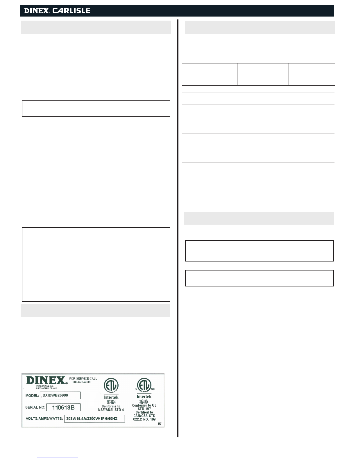
MODEL
DXIDWB20900 DXIDWB30900
Number of Stacks 2 3
Capacity Per Stacks
(Bases-Plates)
Total Capacity
(Bases-Plates)
OVERALL DIMENSIONS
Length 35.36" (89.8 cm) 45.00" (114.3 cm)
Depth 23.68" (60.1 cm) 23.68" (60.1 cm)
Height 42.96" (109.2 cm) 42.96" (109.2 cm)
ELECTRICAL REQUIREMENTS
Voltage/Phase 208V/220V/240V/1P 208V/220V/240V/1P
Amperage (at 208V) 15.4, 14.5, 13.3 30.8, 29.0, 26.7
Cycle 60 60
NEMA Plug Configuration 6-20P 6-50P
Shipping Weight 260 lb (117.9 kg) 320 lb (145 kg)
DXIDPC20120 DXIDPC30180
DXIDPWB20900
60-75 60-75
120-150 180-225
INSTALLATION
ATTENTION: Installation of this equipment should be performed
only by persons qualied or licensed to install electrical equipment.
!
• Adjustments and service work should be performed only by
qualied service technicians.
• This equipment is intended for commercial use only. Not for
household use.
• Use of other than genuine Dinex replacement parts or service
work performed by those other than authorized Dinex service
agents will void the warranty.
• Do not use corrosive cleaners on the equipment. Use
only mild detergents.
INFORMATION
INFORMATION ON THIS SECTION: When contacting customer
service please provide the following information located on the product
identication plate:
IDENTIFICATION PLATE
• Model number
• Serial number of the equipment (identication plate)
• Description of the part
• See Manual for item number
SET UP
INFO: Installation of this Equipment should be performed by
persons qualied or licensed to install electrical equipment only.
!
It is the responsibility of the installer to comply with all local codes.
NOTE: The installation instructions are similar for all models of
base/plate heaters.
!
1. Remove all external packing materials and inspect for
damage. Keep packing materials if damage is discovered.
2. Remove all tape and protective coverings from unit and
all parts.
3. IMPORTANT: Lift the self-leveling dispenser units and
corrugated packing materials out of the cabinet.
4. Wipe all surfaces of the cabinet and self-leveling dispensers
with a clean damp cloth, then dry thoroughly.
5. All models are equipped with self-leveling mechanisms that are
removable through the top of the unit so that adjustments can be
made to the extension springs. By adding or removing springs,
proper dispensing can be obtained.
Different serial numbers for each unit. Check the compatibility of
machine voltage and amperage with electrical connections.
Convection Heated Plate and Base Dispenser | 3
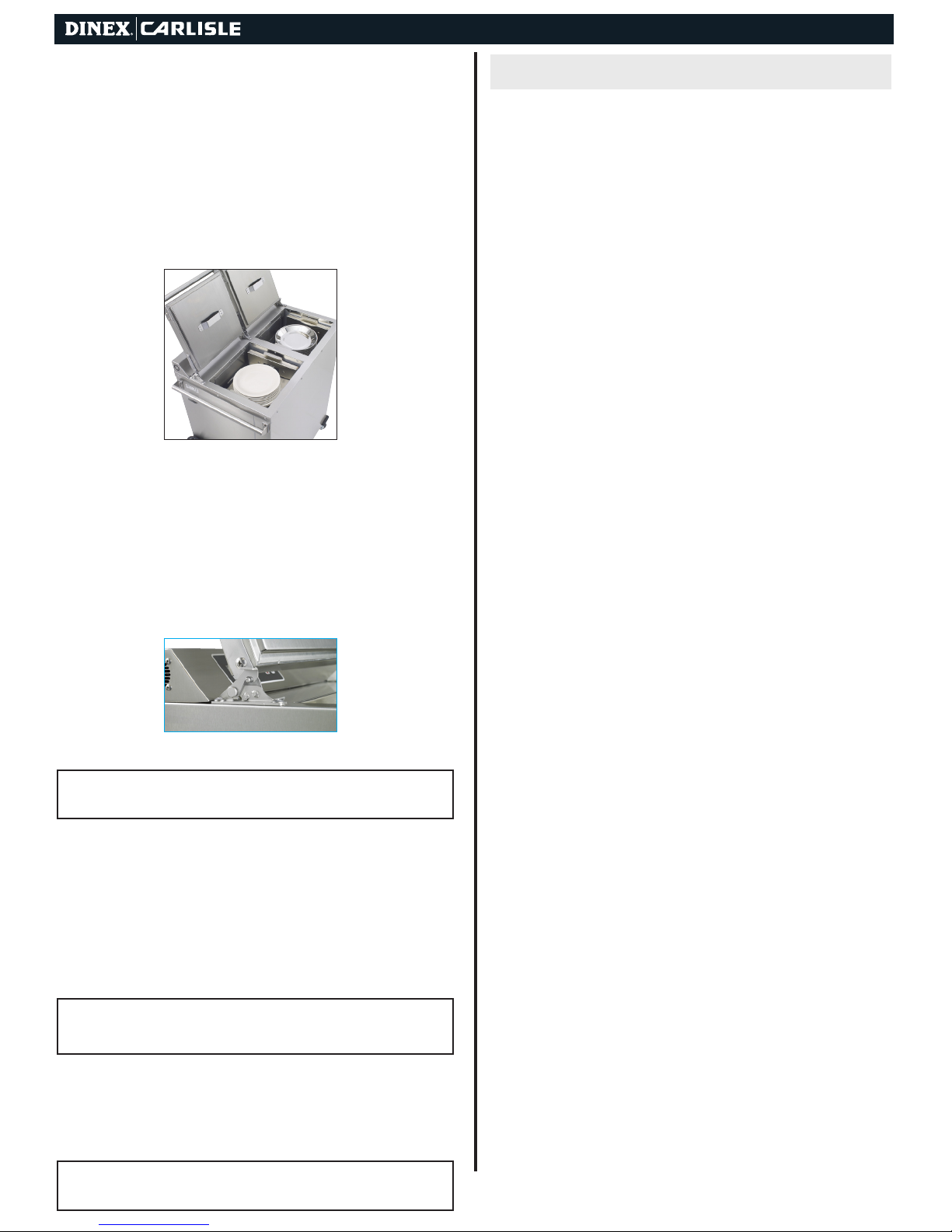
6. To set the proper spring tension and dispensing level,
place ten wax bases in the self-leveling dispenser on right
side of unit (Figure 1). Add or remove springs by hooking or
unhooking the bottom of the spring from the moving carriage
as necessary, until the top wax base is positioned at the
top of the dispenser unit (Figure 2).
NOTE: Steps 6 -8 are for Combination Plate/Base Heaters but may
!
be followed accordingly for plate or base only dispensers. Spring
adjustment not covered under warranty.
Plate Cavity
Figure 1
7. Repeat step 6 with plates for the other self-leveling
dispenser unit. In general, fewer springs will be needed to
maintain proper level for plates than for bases.
Pellet/Wax
Base
Figure 2
ELECTRICAL
Refer to the General Information Section on page 2, your
local code or the National Electrical Code to be sure the unit is
connected to the proper power source. A protected circuit of
the correct voltage and amperage must be available for
connection of the line cord. Place the unit near enough to the
electrical outlet so the power cord is not stretched or strained.
Once the unit is properly located, push down on the two caster
brakes to lock them into place. All base/plate heaters are
provided with a NEMA plug type 6-20P (2 Silo) or 6-50P
(3 Silo).
WARNING: Every base/plate heater is fitted with a grounded power
cord and must be connected to a properly grounded receptacle.
!
Each receptacle must be wired to a dedicated circuit breaker rated
at not more than 20 amps (2 Silo) or 50 amps (3 Silo).
WARNING: To prevent electrical shock hazard, the main power
switch must be turned to “off” position and the heater disconnected
!
from the power source whenever performing service or
maintenance.
WARNING: Hazardous voltage inside back of cabinet. Only
qualied personnel familiar with electrical circuits, service manual,
!
and service procedures should open or work inside unit.
8. Remove all bases and plates from the self-leveling
dispensers, and carefully lower the self-leveling
dispensers back into the cabinet, taking care to place
base and plate dispensers in the appropriate side.
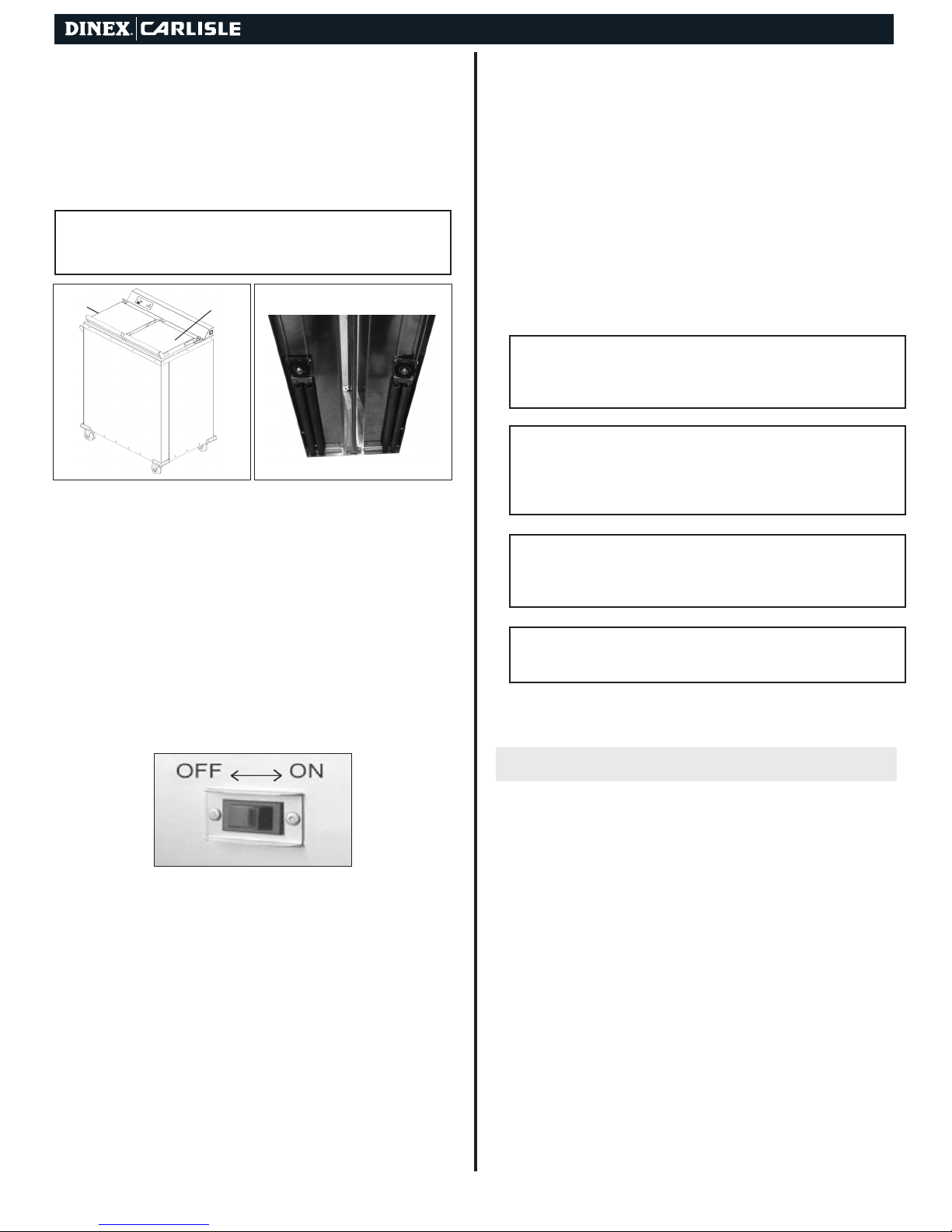
9. Be sure the power switches are in the OFF position before
plugging the power cord into the electrical outlet (Figure 3).
Figure 3
10. Select a location within reach of a 208, 220, 240 VAC,
60 Hz grounded NEMA No. 6-20R (2 Silo) or NEMA
No. 6-50R (3 silo) electrical outlet.
11. Place the unit near enough to the electrical outlet so
that the power cord is not stretched or strained when
plugged in.
12. When unit is properly located, engage the two caster
brakes by pushing down on the wheel brake lever.
WARNING: Unit must not be run continually and must be turned off
after final meal service. Warranty may be voided if used improperly.
!
OPERATION INSTRUCTIONS
START-UP
Overview
These units are designed to heat stainless steel bases and
china plates. The fan motor, heating element, and power indicator light will come on once the unit is turned on.
The fan motor will begin to circulate the heated air in
and around the plates/bases in a convection process that
promotes a quick and even heat absorption by the
plates/bases.
Once the air inside the cabinet has reached the desired and
preset temperature, the thermostats will continue to maintain
this temperature by regulating the power to the heating
element. The fan motor will run as long as each compartment
is energized.
13. See ELECTRICAL and START-UP sections before
plugging unit into power supply.
Convection Heated Plate and Base Dispenser | 4
Operation
1. Plug the unit into the electrical outlet.
2. Lift open lid until it latches securely in safety latch (FIGURE
5). Place bases and plates into the self-leveling dispensers
as required, or until the dispensers are filled to the top.
Be sure to place each into the appropriate side, as marked
(Figure 4). Placing plates in the base side will overheat and
may damage plates. Bases will not heat up to proper
temperature if placed in the plate side. Always keep the
load leveled on the shelf or it could bind.
Figure 4
3. Close lids on the top of the unit by lifting up on the safety
latch (FIGURE 5).
4. Turn the power switch to the ON position. Green LED on
switch will illuminate.
5. Heat-up time period for bases and plates varies, depending on
number and style of each. Minimum heat-up time for a full unit
is one hour for lunch and dinner meals, and an hour and a half
for morning breakfast meal.
Dispensing
CAUTION: Operators should always wear gloves or use base/plate
lifters when dispensing.
!
After the unit is turned off, the bases/plates remaining inside
the unit will remain hot for some time.
Operating Thermostats & Hi-Limit Thermostats
Figure 5
PROGRAMMING
Operation: At power on the display will indicate “020” and the
program version for a few seconds. The control will then start
the Preheat timing cycle and start controlling the heaters to
the Preheat temperature setting. The display will alternate the
3 horizontal bars indicating Preheat delay. When the Preheat
cycle time expires the display will change and rotate a segment
counterclockwise around the perimeter of the display, this
indicates the Preheat cycle is ended and the control will start
the Ready cycle. The control will now maintain the heaters at
the preset Ready Temperature settings until power is removed
from the unit.
Cycle Time Adjustment: Whenever the unit is on you can
revise the Preheat time, Ready Delay time, Preheat heater
temperatures and Ready Delay heater temperatures. To set
the time settings press the Time button for approximately 5
seconds, the display will alternate “PrE”, “Ht” and the current
setting. The LEDs will be off. Press either the UP or DOWN
setting button to change the time. When done press the Time
button and the display will alternate “rdY”, “Ht” and the current
setting. When done press and hold the time button for 2
seconds the changes will be saved, or do not press any
button, after 5 seconds the unit will automatically exit and save
the changes. The control will use the new time setting when a
new timing cycle is initiated. A timing cycle in process will
continue unchanged.
Temperature Setting Adjustment: To set the individual Heater
setpoint temperatures press and hold the Temperature
button for approximately 5 seconds, the display will alternate the
Preheat settings, “PrE” “Ht” and the current setting for the lower
heater and the lower heater LED will be On. Press either the UP
or DOWN setting button to change the temperature. To select
the upper heater setting, press and release the Temperature
button, the display will now flash the upper heater setting and
the upper heater LED will be On. Again press either the UP or
DOWN setting button to change the temperature. When done
press the temperature button, the display will now alternate the
Ready settings, “rdY” “Ht” and the current setting for the lower
heater and the lower heater LED will be On. Press either the UP
or DOWN setting button to change the temperature. To select
the upper heater setting, press and release the Temperature
button, the display will now flash the upper heater setting and
the upper heater LED will be On. When done press and hold
the Temperature button for 2 seconds the changes will be
saved, or do not press any button, after 5 seconds the unit
will automatically exit and save the changes. The temperature
changes will take affect immediately
All thermostats are accessible by removing the back louvered
panel. There are separate Hi-Limit thermostats for the Base &
Plate sides.
CAUTION: Turn unit OFF and unplug prior to the removal of the
back panel. Only qualied service personal should remove the back
!
panel and perform service work.
Both Hi-Limit thermostats are non-adjustable. However, they
can be reset by pushing the reset button located in the center
of the thermostat. Replace back panel and connect electrical
power to the dispenser.
CAUTION: Reset of the Hi-Limits & Adjustment of the Base & Plate
thermostats are not covered under warranty.
!
Changing Default Units of Measurement: To set the degree F
or C temperature display press and hold the Temperature button for approximately 2 seconds, the left display will flash the
current setting for the lower heater and the lower heater LED
will be On. Press both the UP and DOWN setting buttons
simultaneously for approximately 2 seconds, the display will
show the current F or C setting. Press either the UP or DOWN
setting button to change the F or C setting. When done press
and Hold the Temperature button for 2 seconds, the changes
will be saved, or do not press any button, after 5 seconds the
unit will automatically exit and save the changes.
Convection Heated Plate and Base Dispenser | 5
ALARMS
If either Temperature Sensor is “open” or not plugged in, the
Audio Alert will sound, the corresponding heater output will be
turned OFF, the Display will show “Opn”, and the LED indicator
for the heater will turn On. The Audio Alert can be cancelled by
pressing any of the buttons. If this alarm occurs during a timing
cycle, the timer will be cancelled; when probe is corrected the
timing cycle will restart.
If either Temperature Sensor is “shorted”, the Audio Alert will
sound, the corresponding heater output will be turned OFF, the
Display will show “Err”, and the LED indicator for the heater will
turn On. The Audio Alert can be cancelled by pressing any of
the buttons. If this occurs during a timing cycle, the timer will be
cancelled; when probe is corrected the timing cycle will restart.
If the internal memory has been damaged, the Display will show
“dft” on power up and the default Timer and Temperature values
will be used.
NOTE:
!
Default Temperature Setpoints:
Lower Heater Base Cavity: 330°F
Upper Heater Base Cavity: 330°F
Lower Heater Plate Cavity: 210°F
Upper Heater Plate Cavity: 180°F
Casters
1. Check casters for freedom of movement and proper brake
operation.
2. Maintain casters free of debris. (mop strings, paper, plastic,
hair nets, etc.)
3. Clean or replace as required.
Cord and Plug
1. Inspect plug blades for distortion and replace if any blades
are missing, bent or broken.
2. Inspect cord wiring for integrity at termination points by
having qualified service person remove the back panel from
the cabinet. Make sure the cord sheathing extends into the
cabinet interior. If wires are showing on the outside of the
cabinet, remove the unit from use and have repairs made
before turning on power to the unit.
Dispensing Mechanism
Periodically check springs for proper dispensing by filling each
cavity with bases
are removed. If bases
overloaded, adjust or replace springs.
/plates
and checking to see that it indexes as they
/plates
do not index properly, and unit is not
TROUBLESHOOTING
MAINTENANCE
CLEANING
CAUTION: Make sure unit is unplugged and cool before attempting
to clean.
!
The following procedures should be followed during the regular
cleaning routine on all of the plate & base heaters.
1. Turn the unit off, disconnect the plug from the outlet, and
allow the cabinet to cool. Remove plug by pulling it straight
out. Never pull on cord.
2. Pull the elevator mechanisms up and out, place them on a
work surface. You can wipe down the mechanisms with a
damp cloth to clean them.
3. Place the elevator mechanisms back inside the cabinet and
clean the outside of the cabinet with a mild, non-abrasive
soap or detergent in a warm water solution. A commercial
stainless steel cleaner can also be used for this procedure.
NOTE: Do not use abrasives, harsh chemicals, or cholorine
products for cleaning.
!
WARNING: Do not steam or pressure clean or hose down the
cabinet. This could damage the equipment and possibly cause an
!
electrical shock to the operator.
CAUTION: Thermostat adjustment should only be made by qualied
personnel. Thermostat adjustment not covered under warranty.
!
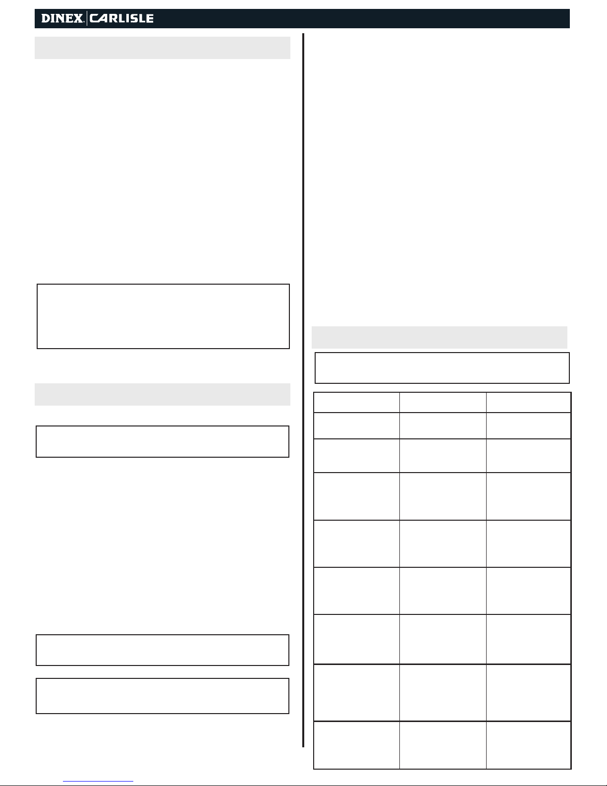
PROBLEM REMEDYPOSSIBLE
Unit does not heat, but fan is
operating.
Unit heats, but fan does not
blow.
Unit does not operate and
power indicator light does not
come on.
Unit does not operate & light
does not come on.
Base/plate temperature is too
low, but fan is operating.
Base/ plate temperature is
too high, and fan is operating.
Dispenser binds.
Cabinet does not roll easily. 1. Debris on wheel or axle.
1. Loose wiring
2. Defective heating element.
1. Defective motor.
2. Jammed or loose fan blade
3. Loose wiring.
1. No power.
2. Open Hi Limit.
3. Defective power switch
4. Loose wiring
1. No power.
2. Bad power switch.
3. Loose wiring.
1. Thermostat set too low.
2. Fan blade is jammed or loose
3. Cover is open.
1. Thermostat is set too high.
2. Closed control.
3. Closed high limit switch.
1. Improper springs
2. Debris on guide rods.
2. No lubrication.
1. Check & secure wiring.
2. Replace heating element.
1. Replace motor.
2. Replace or tighten blade.
3. Determine fault & correct.
1. Make sure plug is connected
& switch is ON.
2. Check for power to receptacle.
3. Replace power switch.
4. Check and secure wiring.
1. Make sure plug is connected
& switch is ON. Check for
power to receptacle.
2. Replace power switch.
3. Check and secure wiring.
1. Readjust thermostat on
plate side. Replace
Thermostat on base side.
2. Replace or tighten blade.
3. Close cover.
1. Readjust thermostat on
china plate side. Replace
Thermostat on base side.
2. Replace control.
3. Replace high limit switch.
1. Depending on contents, use
correct number of springs,
make sure identical number
& size of springs are on each
dispenser.
2. Clean off debris.
1. Clean out debris.
2. Lubricate axles with load
bear
ing grease. Lubricate
swivel bearings with
30-weight oil.
 Loading...