

Dimplex BFSL33 Installation Manual
Installation Guide
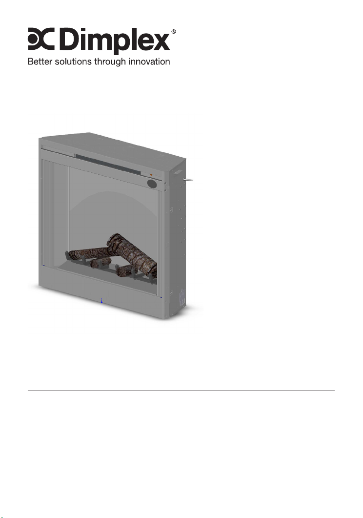
Model
BFSL33
IMPORTANT SAFETY INFORMATION: Always read this manual rst
before attempting to install or use this replace. For your safety, always
comply with all warnings and safety instructions contained in this manual
to prevent personal injury or property damage.
To view the full line of Dimplex products, please visit
www.dimplex.com
7211030100R03
Table of Contents
Listing and Code Approvals ...................................3
Model Specications. . . . . . . . . . . . . . . . . . . . . . . . . . . . . . . . . . . . . . . . .3
Step-by-Step Installation . . . . . . . . . . . . . . . . . . . . . . . . . . . . . . . . . . . . .3
Section A: Installation information .............................4
Framing Dimensions .......................................4
Trim mounting ............................................4
Mounting Flanges .........................................5
Section B: General Electrical Information. . . . . . . . . . . . . . . . . . . . . . . .5
Recommended Power Supply Wire Specications ................5
Voltage Selector Switch Location. . . . . . . . . . . . . . . . . . . . . . . . . . . . . .6
Section C: Direct Power Wiring ................................7
240V Installation ..........................................7
120V Installation ..........................................8
120V Installation - No Heat Installation .........................9
Section D: Alternate Control Options ..........................10
120V Main Power Wall Switch. . . . . . . . . . . . . . . . . . . . . . . . . . . . . . .10
120V Main Power Wall Switch - No Heat. . . . . . . . . . . . . . . . . . . . . . .12
120V Heater Wall Switch Control. . . . . . . . . . . . . . . . . . . . . . . . . . . . .14
120V Wall Mounted Thermostat. . . . . . . . . . . . . . . . . . . . . . . . . . . . . .15
120V / 240V Wall Mounted Flame Override Switch. . . . . . . . . . . . . . .17
Wall Remote - WRCP-KIT ..................................18
Unit Internal Wiring Diagram .................................19
!
NOTE: Procedures and techniques that are considered important enough
to emphasize.
CAUTION: Procedures and techniques which, if not carefully followed, will
result in damage to the equipment.
WARNING: Procedures and techniques which, if not carefully followed, will
expose the user to the risk of re, serious injury, or death.
2
www.dimplex.com
LISTING AND CODE APPROVALS
The BF series replaces have been tested in accordance with the UL 2021 and
CSA C22.2 No. 46 standards for xed and location-dedicated electric room
heaters.
MODEL SPECIFICATIONS
Voltage
(Volts)
120/120/
208/240
!
NOTE: Power ratings shown include LED lights and motors (10 watts)
Rated
Power
(Watts)
8/1223/
1823/2423
Remote
Control
3 Stage Optional 0.07A 10.2A 8.7A 10.1A
Wall
Thermostat
No Heat
120 Volt
WARNING: The installation of the replace unit must comply with the appli-
cable Local and/or National Electrical Codes and utility requirements. This
installation should be entrusted to duly qualied personnel where required
by law.
120
Volt
AMPS
208 Volt
240
Volt
STEP-BY-STEP INSTALLATION
!
NOTE: Please read all instructions before installing.
1. Rough in framing opening following the recommended dimensions located
in Section A: Framing Dimensions.
2. Allow 8” (20.3 cm) of service cable for connecting power supply wire to
junction box on replace when installing before nishing wall. Allow up to
4’ (121.9 cm) of service cable for connecting power supply wire to junction
box on replace when installing after nishing wall. Remove the outer
jacket and strip the individual conductors ½” (1.3 cm) from the end.
3. Loosen the screw securing the junction box cover and remove the cover.
4. Remove knockouts, if necessary, or use the provided cable clamp.
5. Place unit in position in the framed opening, level with shims if necessary
and attach unit to frame using mounting anges provided (Figure 3).
6. Unit is factory wired for 208/240V power supply. If 120V operation is
required, slide the switch and recongure the wiring (Section C). Wires L1,
L2, N & G are attached to the rear of the junction box cable clamp for easy
access.
!
NOTE: If wiring unit to operate with NO heat a dedicated circuit may not
be required.
7. Wire a dedicated, properly fused circuit with a 15amp rating for the appropriate voltage (120V, 208/240V). See Section C for factory setting wiring.
8. Make wall switch and or wall mounted thermostat connections as outlined
in Section D.
9. Place all connectors inside the unit and secure the junction box cover to
unit. Ensure that the cable clamp grips only the jacket of service cable,
thermostat and if applicable wall switch lines.
3
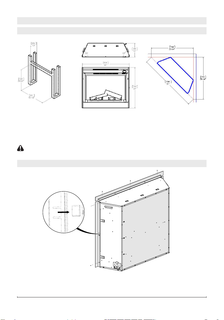
SECTION A: INSTALLATION INFORMATION
FRAMING DIMENSIONS
Figure 1
Rough-In Framing Dimensions
This replace is a zero clearance design. No combustibles can be placed on
the top surface of the replace. Combustibles may be installed to the edge of
the unit. Four mounting anges on the sides of the unit are provided to facilitate installation. Insulation and vapor barrier should be placed a minimum of 2”
(5.1 cm) from the unit.
CAUTION: Ensure installation does not allow replace to be in direct con-
tact with building vapor barrier or insulation and meets all local building code.
Firebox Dimensions
Rough-In Corner Framing
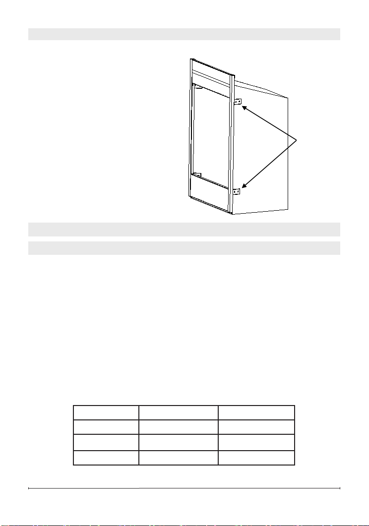
TRIM MOUNTING
Figure 2
This replace comes with three trim pieces, top and two sides. The top piece is
secured with screws at either end and one in the middle. The two side pieces
require a tab to be inserted in the center slot then secured with a screw at the
top and bottom.
4
www.dimplex.com
Mounting
MOUNTING FLANGES
Figure 3
!
NOTE: The trim should be in-
stalled before securing the rebox in
the opening.
There are two mounting anges
located on each side of the replace
insert.
From the inside of the unit, bend tabs
outward and mount to the inside of
the framing using suitable hardware.
SECTION B: GENERAL ELECTRICAL INFORMATION
RECOMMENDED POWER SUPPLY WIRE SPECIFICATIONS
• For 120V installations use two conductor, non-metallic sheath cable with
ground wire (3 wires total) for the incoming power supply on replace inserts. Use the appropriate wire to meet local and national electrical codes
for rated power consumption.
• For 208V / 240V installations use three conductor, non-metallic sheath
cable with ground wire (4 wires total) for the incoming power supply on
replace inserts. Use the appropriate wire to meet local and national electrical codes for rated power consumption.
Two conductor, non-metallic sheath cable with ground wire (3 wires total) is
recommended for installation of a wall mounted thermostat and/or wall switch
for use on replace inserts. Use appropriate wire to meet local and national
electrical codes for rated power consumption. All wire gauges should match
the recommended wire sizes shown below.
Flanges
Voltage Wire Gauge Fuse Rating
120 Volts 12 Gauge 15 Amp
208 Volts 12 Gauge 15 Amp
240 Volts 12 Gauge 15 Amp
5
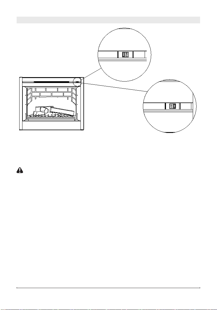
VOLTAGE SELECTOR SWITCH LOCATION
!
IMPORTANT: Ensure that the incoming power supply voltage matches the
setting of the voltage selector switch.
!
NOTE: The voltage selector switch is located inside the exhaust panel on
the top right hand corner.
CAUTION: When changing the voltage selector switch from 240V to 120V
ensure that the power supply is turned off.
!
NOTE: Carefully insert a at headed screwdriver inside the exhaust panel
to change the switch from 240V (230 position) to 120V (115 position).
When wiring the unit for 208V / 240V the voltage selector switch should be in
the 230V position.
When wiring the unit for 120V the voltage selector switch should be in the
115V position.
6
www.dimplex.com
 Loading...