

Page 1
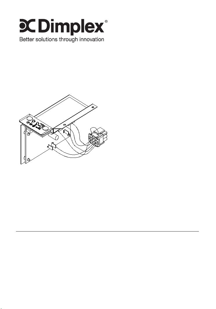
Installation Guide
Optional Remote
Control
Model Numbers:
BFRC-KIT
BFRC-KIT-OP
IMPORTANT SAFETY INFORMATION: Always read this manual rst
before attempting to install. For your safety, always comply with all
warnings and safety instructions contained in this manual to prevent
personal injury or property damage.
To view the full line of Dimplex products, please visit
www.dimplex.com
7206620100R07
Page 2
Table of Contents
Welcome & Congratulations . . . . . . . . . . . . . . 3
IMPORTANT INSTRUCTIONS .............. 4
Remote Kit Installation ...................5
Installation Set Up .....................5
Install Remote Control Receiver ..........6
Remote Control Initialization/Reprogramming . . . . .7
Operation............................... 7
Remote Control Usage .................8
Maintenance ...........................9
Battery Replacement ...................9
Warranty . . . . . . . . . . . . . . . . . . . . . . . . . . . . . . 9
!
Always use a qualied technician
or service agency to repair
this replace.
NOTE: Procedures and
techniques that are
considered important
enough to emphasize.
CAUTION: Procedures and
techniques which, if not
carefully followed, will result
in damage to the equipment.
WARNING: Procedures
and techniques which, if not
carefully followed, will expose
the user to the risk of re,
serious injury, or death.
2
www.dimplex.com
Page 3
Welcome & Congratulations
Thank you and congratulations for choosing to purchase an electric
replace from Dimplex, the world leader in electric replaces.
Please carefully read and save these instructions.
CAUTION: Read all instructions and warnings carefully before
starting installation. Failure to follow these instructions may result in a
possible electric shock, re hazard and will void the warranty.
NO NEED TO RETURN TO THE STORE
Questions with operation or assembly? Require Parts Information?
Product Under Manufacturer’s Warranty?
Contact us at: www.dimplex.com/customer_support
For Troubleshooting and Technical Support
OR Toll-Free 1-888-DIMPLEX (1-888-346-7539)
Monday to Friday 8:00 a.m. to 4:30 p.m. EST
3
Page 4

IMPORTANT INSTRUCTIONS
① Read all instructions before
using this appliance.
④ Do not use outdoors.
⑤ Use this appliance only as
② Any repairs to this appliance
should be carried out by a
qualied service person.
③ Under no circumstances
should this appliance be modied.
Parts having to be removed for
servicing must be replaced prior
to operating this replace again.
described in this manual. Any
other use not recommended by
the manufacturer may cause re,
electric shock or injury to persons.
SAVE THESE INSTRUCTIONS
4
www.dimplex.com
Page 5

Remote Kit Installation
Installation Set Up
Open steel curtain (remove 1.
glass doors if applicable).
Remove two screws on log 2.
grate and remove log grate.
(FIGURE 1)
Pull front edge of plastic ember 3.
bed grate up and forward until
rear tab releases from the
ledge located at the bottom of
the mirror. (FIGURE 2)
!
NOTE:Log set ts tightly
into rebox, some force may be
necessary to remove.
Locate and remove the two 4.
screws on the removable
bracket. Remove the bracket.
(FIGURE 3)
Locate and depress the 5.
mounting tabs on the plug
connector to remove the
‘dummy plug’.
(FIGURE 3)
FIGURE 1
Screws
Manual Controls
FIGURE 2
Back
Ledge
Rear
Tab
FIGURE 3
Side Section
Log
Emberbed
Front
Edge
!
NOTE: Keep the ‘dummy plug
in a safe place. You will need it if
you decide to uninstall the remote
control to operate the replace
manually.
5
Removable
Bracket
Bracket and “Dummy Plug”
Depress
Mounting
Tabs
www.dimplex.com
Page 6

Remote Kit Installation
Install Remote Control Receiver
Locate and insert the plug 1.
connector on the remote
control bracket into plug
connector on the replace.
(FIGURE 4)
Place antenna under remote 2.
bracket.
Locate and install the two 3.
screws on the remote control
bracket.
Replace the log by inserting 4.
front edge and pushing the
back down until rear tab snaps
under back ledge (FIGURE 2)
and the logs are resting against
mirror.
5. Replace log grate using two
screws previously removed.
FIGURE 4
Plug
Connector
Remote Control Receiver
FIGURE 5
Manual Controls & Indicator Lights
6
Page 7

Operation
Remote Control
The remote control has a range
of approximately 50ft. (15.25m). It
does not have to be pointed at the
replace and can pass through
most obstacles (including walls).
It is supplied with one of 2, 187
independent frequencies, in the
factory, to prevent interference
with other units.
Remote Control Initialization/ Reprogramming
Follow these steps for remote
control initialization and if
required, re-initialization:
Ensure that power is supplied 1.
through main service panel.
Access the manual controls, 2.
(remove the glass doors if
applicable) pull the right hand
steel curtain to the outside of
the unit. (FIGURE 5)
(Figure 6-A) for ve (5)
seconds. The Level 1
Indicator Light (Figure 6-D)
will then ash for 10 seconds.
Within7. the 10 seconds
press the ON button located
on the remote control
transmitter. (Figure 7) This
will synchronize the remote
control transmitter and
receiver.
Figure 6
D
E F
A
B C
Locate manual controls.3.
Move the 3-way switch to 4.
“Remote”.
Activate the main power 5.
switch, the red Level 1
Indicator Light will ash .
(Figure 6-D)
Press and hold the On button 6.
on the manual controls
7
www.dimplex.com
Page 8

Operation
Remote Control Usage
The remote control operation can
be adjusted, depending on the
season and desired effects, by
toggling the main mode selector
switch built into the replace.
The position of the switch will
dictate the available functions that
the remote transmitter will cycle
through.
A. On Button
Pressing this button toggles
sequentially through the three
levels of the replace.
Mode Selector Set at “O”: •
Only Flame Effect at all 3
levels.
Mode Selector Set at “--”: •
Pressing once activates Level
1 - ame effect only, two and
three times activates Level 2 -
ame effect and Purire™.
Mode Selector Set at “=”: •
Pressing once activates Level
1 - ame effect only, twice
activates Level 2 - ame
effect and Purire™, three
times activates Level 3 -
ame effect, Purire™ and
heat.
B. Off Button
Pressing this button at any time
will shut the unit off.
C. Manual Selection Switch
Switches the operation of the
replace between the different
modes of the replace:
OFF (center): Makes the unit •
inoperable.
MANUAL (top): All functions •
of the replace are controlled
by the On and Off buttons as
described above (A, B).
REMOTE (bottom): All •
functions of the replace are
controlled by the Remote
Control.
D. LED Indicators
Depicts which of the three (3)
levels the replace is currently
operating at: Level 1 - , Level
2 - or Level 3 - .
Figure 7
ON
Button
OFF
Button
Battery
Battery
Cover
Remote Control Transmitter
8
Page 9

Maintenance
Battery Replacement
(Figure 7)
To replace the battery:
Slide battery cover open on •
the hand held transmitter.
Correctly install one (1) 12 •
Volt (A23) battery in the battery holder.
Close the battery cover.•
Warranty
All Dimplex accessories are warranted against defects in workmanship
and materials for two years from date
of sale. This warranty does not apply
to damage from accident, misuse, or
alteration, nor where the connected
voltage is more that 5 % above the
nameplate voltage, nor to equipment improperly installed or wired or
maintained in violation of the instruction sheet. This limited warranty applies only to purchases made in any
province of Canada except for Yukon
Territory, Nunavut, or Northwest Territories or in any of the 50 States of the
USA (and the District of Columbia)
except for Hawaii and Alaska. This
limited warranty applies to the original
purchaser of the product only and is
not transferable. No other written or
oral warranty applies. No employee,
agent, dealer or other person is
authorized to give any warranties on
behalf of Dimplex. The customer shall
be responsible for all costs incurred
in the removal or reinstallation and
shipping of the product for repairs.
Within the limitations of this warranty,
inoperative units shall be returned
to the nearest Dimplex authorized
service center, and we shall repair or
replace, at our option, at no charge
to you with return freight paid be
Dimplex. It is agreed that such repair
or replacement is the exclusive remedy available from Dimplex and that
DIMPLEX IS NOT RESPONSIBLE
FOR DAMAGES OF ANY KIND,
INCLUDING INCIDENTAL AND
CONSEQUENTIAL DAMAGE. Some
States do not allow the exclusion or
limitation of consequential damages,
so the above exclusion or limitation
may not apply to you. This warranty
gives you specic legal rights and you
may also have other rights which vary
from state to state.
9
www.dimplex.com
Page 10

Dimplex North America Limited
1367 Industrial Road
Cambridge ON
Canada N1R 7G8
© 2011 Dimplex North America Limited
 Loading...