

Page 1

7205180100REV01
INSTALLATION GUIDE FOR THE
OPTIFLAME ELECTRIC FIREPLACE
LISTINGS AND CODE APPROVALS
The BF series fireplaces have been tested in accordance with the UL 2021and CSA C22.2 No. 46 standards for
fixed and location-dedicated electric room heaters.
MODEL SPECIFICATIONS
Model
Number
BF36E 36”
BF36ST 36”
BF36DX 36”
BF42ST 42”
BF42DX 42”
Description
Economy
Standard
Deluxe
Standard
Deluxe
Voltage
Volts
120/208/240 1650/2340/3025 N/A N/A N/A 13.75 11.25 12.6
120/208/240 1650/2340/3025 Included Included N/A 13.75 11.25 12.6
120/208/240 1650/2340/3025 Included Included Included 13.75 11.25 12.6
120/208/240 1650/2340/3025 Included Included N/A 13.75 11.25 12.6
120/208/240 1650/2340/3025 Included Included Included 13.75 11.25
Rated Power
Watts
Remote
Control
Wall
Thermostat
Refractory
Brick Look
AMPS
120Volt
AMPS
208Volt
NOTE: Power ratings shown include the light bulbs and motor (275 watts)
AMPS
240Volt
12.6
STEP-BY-STEP INSTALLATION (Note: Please read all instructions before installing)
1. Rough in framing opening following the recommended dimensions (Section A: Framing).
2. Allow 8” of service cable for connecting to the junction box on the fireplace. Remove the outer jacket and
strip the individual conductors ½” from the end.
3. Loosen the screw securing junction box cover and remove the cover.
4. Remove knockouts if necessary or use the provided cable clamp.
5. Place unit in position in the opening, level with shims if necessary and attach unit to frame using nailing
flanges provided.
6. Unit is factory wired for 208/240 volt power supply. If 120 volt operation is required, slide the switch and
reconfigure the wiring as covered in section C wiring. Wires L1, L2, N & G are attached to the rear of the
junction box cable clamp for easy access.
7. Wire a dedicated, properly fused circuit with a 20amp rating for the appropriate voltage (120, 208/240).
8. Make wall mounted thermostat and or wall switch connections as outlined in Section C: Wiring.
9. Place all connectors inside the unit and replace the junction box cover, ensuring that the cable clamp grips
only the jacket of service, thermostat and if applicable wall switch lines.
Page 2

SECTION A: FRAMING
Optiflame Dimensions
MODEL A B C D E F
BF36E/ST/DX 35.5” 38.7” 54.0” 38.0” 38.0” 39.5”
BF42ST/DX 41.5” 44.7” 60.0” 42.0” 42.0” 45.5”
Rough-in framing dimensions Optiflame dimensions Rough-in corner framing dimensions
This fireplace is a zero clearance design. Combustibles may be installed to the edge of the unit. A drywall lip at the
top of the unit and four nailing flanges on the sides of the unit are provided on each unit to facilitate installation.
Insulation and vapor barrier should be placed a minimum of 2 inches from the unit.
SECTION B: RECOMMENDED POWER SUPPLY WIRE SPECIFICATIONS
For 120 volt installations use two conductor, non-metallic sheath cable with ground wire for the incoming power
supply on Optiflame fireplace inserts. Use the appropriate wire to meet local and national electrical codes for rated
power consumption.
For 208 / 240 volt installations use three conductor, non-metallic sheath cable with ground wire for the incoming
power supply on Optiflame fireplace inserts. Use the appropriate wire to meet local and national electrical codes for
rated power consumption.
Two conductor, non-metallic sheath cable with ground wire is recommended for installation of a wall mounted
thermostat and/or switch on Optiflame fireplace inserts. Use appropriate wire to meet local and national electrical
codes for rated power consumption. Thermostat/wall switch wire gauge must match the recommended wire sizes
shown below.
RECOMMENDED WIRE AND FUSING REQUIREMENTS
VOLTS WIRE GAUGE FUSE RATING
120 VOLT 12 GAUGE 20 AMP
208 VOLT 14 GAUGE 15 AMP
240 VOLT 12 GAUGE 20 AMP
Page 3
SECTION C: WIRING
NOTE:
The unit is factory configured for 208/240 volt operation
NOTE:
All wiring must be completed prior to installing the unit.
NOTE:
Ensure that the power conversion switch is in the proper position for the required supply voltage prior to connecting
the unit to power supply.
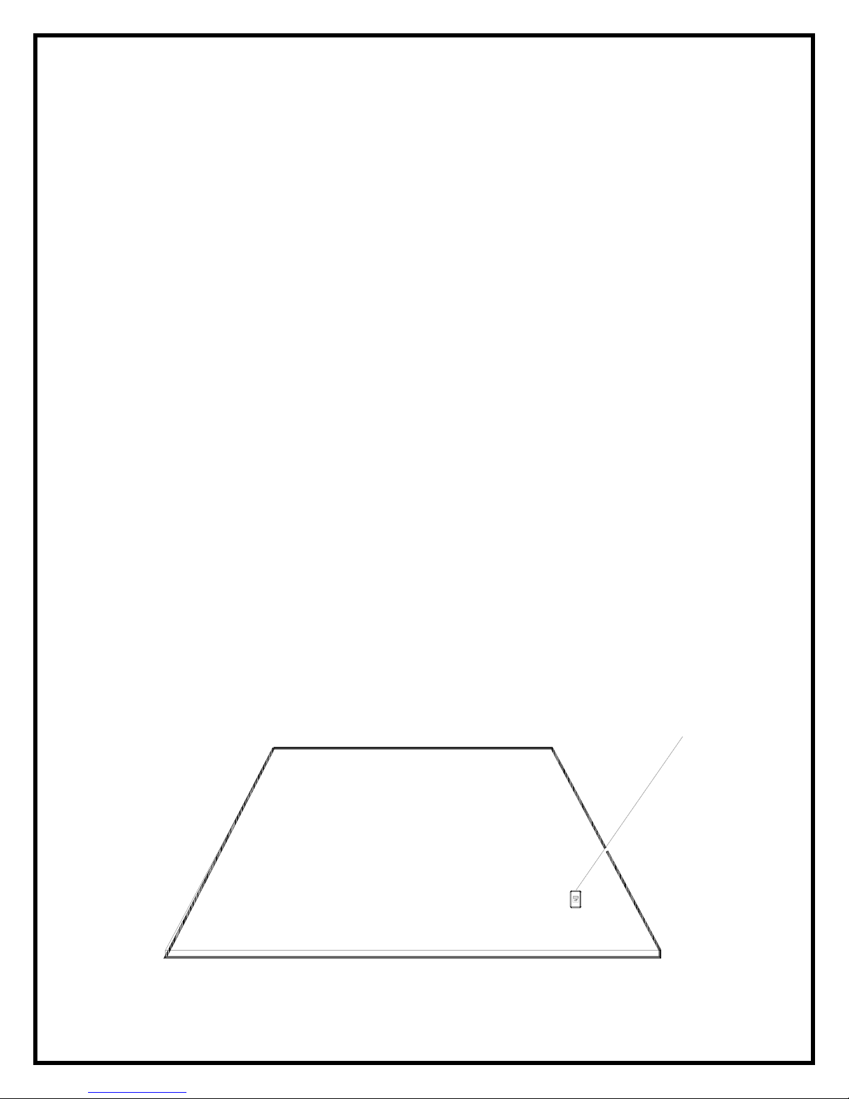
240 VOLT INSTALLATIONS
1. Locate the switch on the top corner of the unit.
2. Ensure that the switch is in the 230 volt position.
3. Loosen the screw securing the junction box cover and remove the cover.
4. Remove the knockouts (if necessary) or use the provided cable clamp.
5. Pull out the four wires marked L1, L2, N, and G.
6. Connect the black L1 wire from the unit to the L1 from the power supply. Connect the red L2 wire from the
unit to the L2 from the power supply. Connect the white N wire from the unit to the to the neutral from the
power supply. Connect the green ground wire from the unit to the ground from the power supply.
7. When the unit has been configured for the appropriate power supply voltage, ensure that all connections
are tight. Insert all the wiring into the unit and secure with a cable clamp.
TO RECONFIGURE FROM 240 VOLT TO 120 VOLT
1. Locate the switch on the top corner of the unit.
2. Flip the switch from 230 volt to 115 volt configuration.
3. Loosen the screw securing the junction box cover and remove the cover.
4. Remove the knockouts (if necessary) or use the provided cable clamp.
5. Pull out the four wires marked L1, L2, N, and G.
6. Connect the black L1 wire from the unit to the L1 from the power supply. Connect the red L2 and white N
wires to the neutral from the power supply. Connect the green ground wire from the unit to the ground from
the power supply.
7. When the unit has been configured for the appropriate power supply voltage, ensure that all connections
are tight. Insert all the wiring into the unit and secure with a cable clamp.
TOP OF FIREPLACE
230 VOLT/115 VOLT SWITCH
Page 4
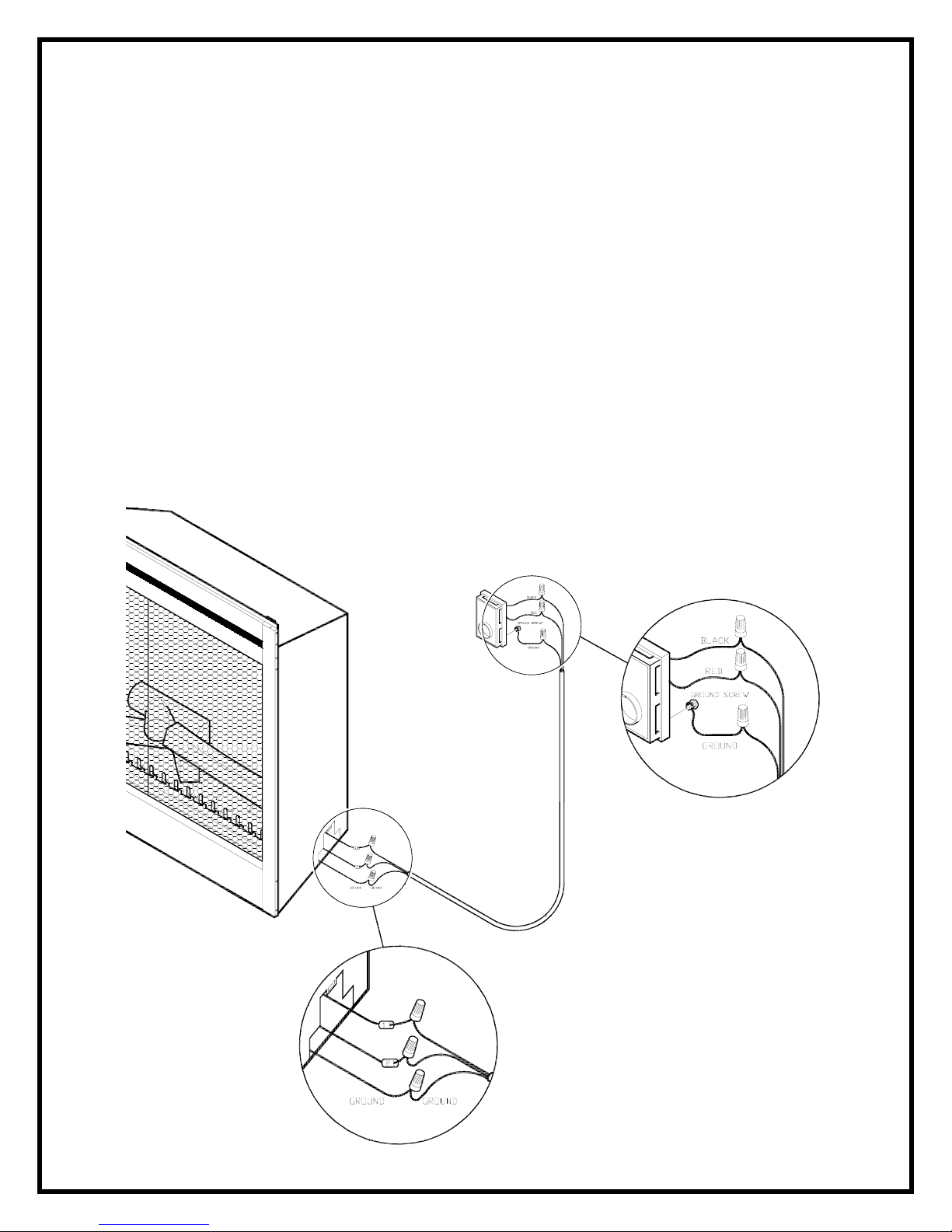
WALL MOUNTED THERMOSTAT WIRING
NOTE:
Wiring of the thermostat must be completed prior to installing the unit.
NOTE:
The following installation instructions are for a single pole thermostat included with the unit.
120 / 240VOLT INSTALLATIONS
The wall mounted thermostat is connected to the fireplace by running a 2 conductor wire with a ground from the
junction box on the back of the unit to the thermostat.
1. Locate the switch on the top corner of the unit and ensure that the power conversion switch is in the proper
position for the required supply voltage.
2. Loosen the screw securing the junction box and remove the cover. Pull out the wire nut that contains wires
marked 1 & 2.
3. Remove the wire nut and separate the wires marked 1 & 2.
4. Connect one of the wires from the thermostat to the wire marked 1 and the other wire to the wire marked 2.
5. Connect the ground wire from the thermostat to the ground wire grouping from the power supply.
6. Ensure that all connections are tight. Insert all the wiring into the unit and secure with a cable clamp.
Page 5

HEATER WALL SWITCH WIRING
NOTE:
Wiring of the wall switch must be completed prior to installing the unit.
NOTE:
When using a wall switch ensure that the switch has a rating of 20 amps.
NOTE:
Only install a wall switch on units that do not have a remote control.
120 / 240VOLT INSTALLATIONS
The wall mounted switch is connected to the fireplace by running a 2 conductor wire with a ground from the junction
box on the back of the unit to the thermostat.
1. Locate the switch on the top corner of the unit and ensure that the power conversion switch is in the proper
position for the required supply voltage.
2. Loosen the screw securing the junction box and remove the cover. Pull out the wire nut that contains wires
marked 1 & 2.
3. Remove the wire nut and separate the wires marked 1 & 2.
4. Connect one of the wires from the wall switch to the wire marked 1 and the other wire to the wire marked 2.
5. Connect the ground wire from the wall switch to the ground wire grouping from the power supply.
6. Ensure that all connections are tight. Insert all the wiring into the unit and secure with a cable clamp.
Page 6

MAIN POWER WALL SWITCH WIRING
NOTE:
Wiring of the wall switch must be completed prior to installing the unit.
NOTE:
Use a single pole, single throw wall switch that is rated for 20 amps.
NOTE:
Only install a wall switch on units that do not have a remote control.
120 VOLT INSTALLATIONS
The wall mounted switch is connected to the fireplace by running a 2 conductor wire with a ground from the junction
box on the back of the unit to the thermostat.
1. Locate the switch on the top corner of the unit.
2. Flip the switch from 230 volt to 115 volt configuration.
3. Loosen the screw securing the junction box cover and remove the cover.
4. Remove the knockouts (if necessary) or use the provided cable clamp.
5. Pull out the four wires marked L1, L2, N, and G.
7. Connect one of the wires from the wall switch to the black L1 wire on the unit, and the other wire to the L1
from the power supply.
8. Connect the red L2 and white N wires to the neutral from the power supply.
8. Connect the ground wire from the wall switch to the ground wire grouping from the power supply.
9. Ensure that all connections are tight. Insert all the wiring into the unit and secure with a cable clamp.
Page 7

MAIN POWER WALL SWITCH WIRING
NOTE:
Wiring of the wall switch must be completed prior to installing the unit.
NOTE:
Use a double pole, single throw wall switch that is rated for 20 amps.
NOTE:
Only install a wall switch on units that do not have a remote control.
240 VOLT INSTALLATIONS
The wall mounted switch is connected to the fireplace by running a 2 conductor wire with a ground from the junction
box on the back of the unit to the thermostat.
1. Locate the switch on the top corner of the unit.
2. Ensure that the switch is in the 230 volt position.
3. Loosen the screw securing the junction box cover and remove the cover.
4. Remove the knockouts (if necessary) or use the provided cable clamp.
5. Pull out the four wires marked L1, L2, N, and G.
6. Connect one of the wires from the wall switch to the black L1 wire on the unit, and the other wire from the
wall switch to the L1 from the power supply.
7. Connect one of the wires from the wall switch to the red L2 wire on the unit, and the other wire from the
wall switch to the L2 from the power supply.
8. Connect the ground wire from the wall switch to the ground wire from the power supply.
9. Connect the white N wire from the unit to the neutral from the power supply.
10. Connect the green ground wire from the unit to the ground from the power supply.
11. Ensure that all connections are tight. Insert all the wiring into the unit and secure with a cable clamp.
Page 8

WIRING DIAGRAM WITH REMOTE CONTROL
Page 9

WIRING DIAGRAM WITHOUT REMOTE CONTROL
Page 10

Approved for use in the United States and Canada
1-888-DIMPLEX
1-888-346-7539
1367 Industrial Road
Cambridge, Ontario
Canada, N1R 7G8
 Loading...