


XL 650
Instruction Manual
Version 6.1
illon
 recision
Products, Inc.
Manufacturers of
The World's Finest
Loading Equipment

On the cover…
The XL 650 is pictured with optional accessories: |
|
Strong Mount (550/650) |
#22051 |
Strong Mount (650 only) |
#22052 |
Aluminum Roller Handle |
#17950 |
Low Powder Sensor |
#16306 |
Bullet Tray |
#22214 |
Powdercheck System |
#21044 |
Electric Casefeeder |
(four sizes available) |
Other accessories available for the XL 650 include: |
|
Video Instruction Manual |
#15064 |
Machine Cover |
#10443 |
Maintenance Kit & Spare Parts Kit |
#97017 |
The Blue Press, Dillon’s monthly catalog, has a complete listing of accessories available for all machines.
Dillon Precision Products, Inc.
8009 E. Dillon’s Way
Scottsdale, AZ 85260
(480) 948-8009
FAX (480) 998-2786
Web Site: www.dillonprecision.com
E-mail: dillon@dillonprecision.com
Technical Support & Customer Service
(800) 223-4570
Part #13524 Spot Manuals XL 650 Folder XL 650 Man. 6.1 9/01 WJC
Table of Contents
|
|
Page # |
Mandatory Safety Measures |
5 |
|
Getting Started |
6 |
|
1. Unboxing your machine |
6 |
|
2. Mounting your XL 650 |
7 |
|
3. Initial Set-Up |
7 |
|
A. Installation of Handle |
7 |
|
B. Installation of the Spent Primer Cup and Cartridge Bin |
8 |
|
C. Installation of the Casefeed Post |
8 |
|
D. Installation of the Casefeed Tube Bracket |
8 |
|
E. Installation of the Optional Casefeeder |
9 |
|
4. Toolhead Overview |
11 |
|
Lubricating Brass |
11 |
|
Pistol Section – Toolhead Set Up |
12 |
|
A. Station One – Installation of the Sizing/Decapping Die |
12 |
|
B. Station One – The Decapping assembly |
12 |
|
C. Station Two – Installation of the Powder Measure Assembly |
12 |
|
D. Station Two – About Powder Bars |
13 |
|
E. |
Station Two – Adjustment of the Powder Die/Powder Funnel |
14 |
F. |
Station Two – Installation of the Failsafe Rod Assembly |
15 |
G. |
Station Three – Installation of the Powder Check System |
16 |
H. |
Station Four – General Information on Bullet Seating |
17 |
I. |
Station Four – Seating Stems |
18 |
J. |
Station Four – Installation and Adjustment of the Seating Die |
18 |
K. Station Five – Installation and Adjustment of the Crimp Die |
18 |
|
Rifle Section – Toolhead Set Up |
20 |
|
A. Station One – About the Case Gage |
20 |
|
B. How to Use the Case Gage |
20 |
|
C. Station One – Installation of the Sizing/Decapping Die |
21 |
|
D. Station One – The Decapping assembly |
22 |
|
E. |
Station Two – Installation of the Powder Measure Assembly |
22 |
F. |
Station Two – About Powder Bars |
23 |
G. |
Station Two – Adjustment of the Powder Die/Powder Funnel |
23 |
H. |
Station Two – Installation of the Failsafe Rod Assembly |
25 |
I. |
Station Three – Installation of the Powder Check System |
25 |
J. |
Station Four – How to Determine the Proper Seating Depth |
26 |
K. |
Station Four – Seating Stems |
27 |
L. |
Station Four – Installation and Adjustment of the Seating Die |
27 |
M. Station Five – Installation and Adjustment of the Crimp Die |
28 |
|
Final Assembly |
29 |
|
1. |
The Primer Magazine |
29 |
2. |
Installation of the Primer Early Warning System |
29 |
3. |
Installation of the Locator Buttons |
30 |
Loading Components Section |
|
|
1. |
Primer System Overview (how it works) |
30 |
2. |
Powder Bar Adjustment |
30 |
3. |
Powder Check System Adjustment |
31 |
|
A. Installation and Adjustment of the Powder Check Rods |
31 |
|
B. Powder Check System demonstration |
32 |
4. |
Filling the Primer System |
32 |
Station Orientation and Loading Funtions |
34 |
|
Caliber Conversion Section |
35-42 |
|
Trouble Shooting |
43-45 |
|
Caliber Conversion Chart |
46-48 |
|
Schematics |
49-58 |
|
MANDATORY SAFETY MEASURES
Reloading small arms ammunition involves the use of highly explosive primers and powder. Handling these materials is inherently dangerous. You should recognize this danger and take certain minimum precautions to lessen your exposure to injury.
Never operate the machine without ear and eye protection on. Call our customer service department at (800) 223-4570 for information on the wide variety of shooting/safety glasses and hearing protection that Dillon has to offer.
•PAY ATTENTION: Load only when you can give your complete attention to the loading process. Don’t watch television or try to carry on a conversation and load at the same time. Watch the automatic systems operate and make sure they are functioning properly. If you are interrupted or must leave and come back to your loading, always inspect the cases at every station to insure that the proper operations have been accomplished.
•SMOKING: Do not smoke while reloading or allow anyone else to smoke in your reloading area. Do not allow open flames in reloading area.
•SAFETY DEVICES: Do not remove any safety devices from your machine or modify your machine in any way.
•LEAD WARNING: Be sure to have proper ventilation while handling lead components or when shooting lead bullets. Lead is known to cause birth defects, other reproductive harm and cancer. Wash your hands thoroughly after handling anything made of lead.
•LOADS AND LENGTHS: Avoid maximum loads and pressures at all times. Use only recommended loads from manuals and information supplied by reliable component manufacturers
and suppliers. Since Dillon Precision has no control over the components which may be used on their equipment, no responsibility is implied or assumed for results obtained through the use of any such components.
Seat bullets as close to maximum cartridge length as possible. Under some conditions, seating bullets excessively deep can raise pressures to unsafe levels. Refer to a reliable loading manual for overall length (OAL).
•QUALITY CHECKS: Every 50100 rounds, perform periodic quality control checks on the ammunition being produced. Check the amount of powder being dropped and primer supply.
•RELOADING AREA: Keep your components safely stored. Clear your work area of loose powder, primers and other flammables before loading.
•COMPONENTS: Never have more than one type of powder in your reloading area at a time. The risk of a mix-up is too great. Keep powder containers closed.
Be sure to inspect brass prior to reloading for flaws, cracks, splits or defects. Throw these cases away.
Keep components and ammunition out of reach of children.
•BLACK POWDER: Do not use black powder or black powder substitutes in any Dillon powder measure. Loading black powder cartridges requires specialized loading equipment and techniques. Failure to do so can result in severe injury or death.
•PRIMERS: Never force primers. If they get stuck in the operation of the machine, disassemble it and gently remove the obstruction.
Never attempt to clear primers that are stuck in either the primer pickup tube or the primer magazine tube. Never, under any circumstances, insert any type of rod
to attempt to force stuck primers out of these tubes. Trying to force primers out of the tube will cause the primers to explode causing serious injury or even death.
If primers get stuck in a primer magazine or pickup tube flood the tube with a penetrating oil (WD40), throw the tube in the garbage and call us for a free replacement. Never attempt to deprime live primers – eventually one will go off. When it does it will detonate the others in the spent primer cup. Depriming live primers is the single most dangerous thing you can
do in reloading and can cause grave injury or death.
•LOADED AMMUNITION: Properly label all of your loaded ammunition (Date, Type of Bullet, Primer, Powder, Powder Charge, etc.).
•BE PATIENT: Our loading equipment is conservatively rated and you should have no trouble achieving the published rates with a smooth, steady hand. If something doesn’t seem right, stop, look and listen. If the problem or the solution isn’t obvious, call us.
The reloading bench is no place to get into a hurry.
We have done everything we know how to make your machine as safe as possible. We cannot, however, guarantee your complete safety. To minimize your risk, use common sense when reloading and follow these basic rules.
• REMEMBER: If your machine does not perform to your expectations, or if you are having technical difficulties, give us a call. Technical Support (800) 223-4570
ALL ELECTRICAL/ELECTRONIC COM-
PONENTS IN DILLON EQUIPMENT ARE
COVERED BY A ONE-YEAR WARRANTY.
5

7 |
8 |
10 |
|
12 |
6
9 |
3 |
4 |
|
||
|
|
11 |
5 |
13
14 15
1
2
16
GETTING STARTED
1. Unboxing Your Machine:
After opening the box, check the contents against the list below. If any items are missing or damaged, call us right away so we can send out a replacement at no charge.
You should have the following:
1.Machine with toolhead and toolhead retaining pins installed
2.Operating handle assembly with washer and lock nut
3.Casefeed mounting post
4.Casefeed tube
5.Casefeed support bracket
6.Primer Early Warning System bag containing:
a.Primer Early Warning System (with AAA battery included)
b.Primer follower rod (16” black plastic rod)
7.Primer system parts bag containing:
a.Powder Measure Failsafe assem-
bly (10” black metal rod w/ hardware)
b.One small and one large primer pickup tube – 12” aluminum tube each with
plastic tip - green tip (large), yellow tip (small)
c.One large and one small plastic tip, (spares)
d.Primer feed disk (2” diameter metal disk w/16 small holes)
e.Primer magazine (15” aluminum tube w/ brass tip)
f.Primer punch assembly. (metal w/spring, approximately 2 x 1/2”)
g.Two steel hitchpins
8.Conversion kit box (empty)
9.Conversion kit includes caliber specific:
a.Powder funnel
b.Casefeed adapter
c.Three locator buttons
d.Shellplate (installed)
e.Station 1 locator (installed)
f.Casefeed arm bushing (installed)
g.Body bushing (installed)
10.Powder system with powder die
11.Accessory box containing:
a.Cartridge bin (blue plastic, approximately 3 x 4 x7”)
b.Ejected cartridge chute (black metal, wrapped in bubble pack)
c.Two 1/4” x 20 x 3”: hex bolts and two 1/4” x 20 nuts
d.Two Aluminum tube clamps
e.Spent primer cup (blue plastic)
f.Extra powder bar
g.Three die lockrings (7/8 x 14” thread)
h.Seven Allen wrenches (1/4”, 3/16”, 5/32”, 9/64”, 1/8”, 3/32”, 5/64”)
12.Casefeed assembly (optional)
13.Casefeed accessory bag containing:
a.Casefeed funnel adapter (white)
b.Spacer washer
c.Casefeed mounting post set screw
14.Mounting hardware kit (optional)
15.Three die set (optional)
16.Powder check system (optional)
6

2. Mounting your XL 650:
A.Locate a sturdy bench at least
24” wide and 14” deep, with 44” of overhead clearance. We suggest a minimum of 1” plywood or equivalent, secured to the back wall. The workbench should be tall enough to place your eye level about 18” above the bench.
Note: It is important that the leading edge of the bench has an overhang of at least 3/4”. If the overhang is less than 3/4”, the crank will interfere with the front of the bench when the operating handle is lowered. Unless you have Strong Mounts, then none of this is necessary.
B. Tools Needed:
You will need the following to mount and set up your machine:
1.Electric drill
2.17/64” drill bit preferred, 1/4” – 9/32” OK
3.Mounting Hardware Kit (#14355) or four 1/4” through bolts with nuts and washers
Note: The bolts should be at least 1 1/2” longer than the thickness of the mounting surface.
4. Two 7/16” wrenches if using kit
FIG 1
C.Drill the mounting holes FIG 1:
1.Using the machine as a template, mark the four holes.
2.Using a 1/4” bit, drill the holes.
FIG 2
D. Bolting the machine to the bench FIG 2:
Note: If you do not have a Mounting Hardware Kit, ensure that you use 1/4” or equivalent through bolts (with large area washers if mounting to wood). Do not use lag bolts or wood screws!
FIG 3
1.Mount the left side of the machine with the small washers on top and the large washers on the bottom FIG 3. Run
the two left side nuts down finger tight.
2.Place the chute/bin bracket FIG 2 on the right side of the machine. As before, place the small washer on top and the large washers on the bottom and thread the nuts.
Note: The chute/bin mount goes under
the two right hand mounting bolts so it must be installed as you are mounting the machine FIG 2. Check the fit of the chute/bin mount. The chute/bin mount
should rest snugly against the frame. Also, make sure that the walls of the chute are parallel and
have not been bent during shipping or installation.
3.Using two 7/16” wrenches, tighten all four bolts down.
3. Initial Set Up
If you ordered your XL 650 for a specific caliber, it comes factory adjusted for that caliber (minus dies) with the appropriate “caliber specific” parts included. In fact, a Dillon technician runs casings and primers through the machine to check its function.
Note: As you assemble your machine, we recommend that you cross check caliber specific parts, included with your machine, with those specified in the caliber conversion chart (pages 42-44). The
point being – if we sent you the wrong part, you’ll want to know it before getting started. Reference page 35 for instructions on how to use the caliber conversion chart.
FIG 4
A.Installation of the handle FIG 4:
1.Hold the washer (see arrow FIG 4) over the hole on the right side of the crank and insert the handle.
2.Place a 5/32” Allen wrench or screw driver through the hole in the handle to help your grip.
3.Tighten the nut using a 7/8” wrench.
7
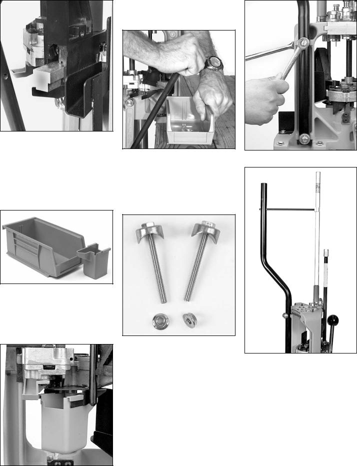
FIG 5
Operate the handle slowly to ensure that the machine operates smoothly. Make sure that the handle and the crank completely clear the bench. Contact with the bench may hinder its range of movement. Observe the movement of the shellplate platform and verify that there is no interference or contact of the case insert slide and the chute/bin mount
FIG 5.
FIG 6
B.Installation of the Spent Primer Cup FIG 7 and Cartridge Bin FIG 6:
1.Raise the platform (i.e., lower the handle all the way).
FIG 7
2.Slide the spent primer cup onto the rails as shown. Make sure when installing the cup that it is on both rails.
FIG 8
3.Place the cartridge bin on the chute/bin bracket. Push the handle aft FIG 8 while sliding the bin toward the handle as shown. With the handle pushed to its full aft position, there should be a space between the handle and bin.
FIG 9
C.Installation of the Casefeed Post
1.Remove the bolts, nuts and clamp from the spacer kit and assemble them as shown in FIG 9.
FIG 10
FIG 11
2.Install the casefeed post as shown in FIG 10. Make sure the bend in the post is facing away from you FIG 11.
3.Using two 7/16” wrenches, tighten the bolts.
D.Installation of the Casefeed Tube Bracket FIG 11.
Install as shown in FIG11.
Note: If you ordered your machine with the optional casefeed assembly, you won’t need to use the casefeed tube bracket. This is because the upper end of the casefeed tube is supported by the casefeed bowl.
8

E.Installation of the Optional Casefeeder FIG 12:
FIG 12
1.Remove the casefeed parts bag from the casefeed bowl and remove the casefeed assembly from the box
FIG 12.
FIG 13
a. Spacer Washer FIG 13: (see casefeeder schematic page 57)
Some calibers call for a spacer washer to be used under the casefeed plate. Installation of this washer raises the plate up a bit to make the feeder function properly with longer pistol cases (such as .357 Magnum, .44 Magnum and .30 M1 – this listing of calibers requiring the spacer is repeated in the caliber conversion chart on pages 46-48 of this manual).
Note: The spacer washer does not come factory installed.
FIG 14
To Install the Spacer Washer:
a.1. FIG 14 Remove the casefeed plate.
a.2. With the casefeed plate removed, disassemble the clutch drive. To do so unscrew the two clutch screws.
a.3. Install the spacer washer as illustrated in the casefeed schematic (page 57). IMPORTANT: The spacer washer goes between the lower clutch and the casefeed plate.
a.4. Reassemble the clutch drive and reinstall the casefeed plate. (Note how the clutch drive engages the drive pin).
FIG 15
b. Clutch Adjustment FIG 15:
Note: The clutch comes factory adjusted (if you don’t have to install the spacer washer you shouldn’t have to adjust the clutch drive).
The two socket-head machine screws (pt# 13732) should be just tight enough for the clutch to drive the casefeed plate under a normal load of brass. To check this, place the casefeed assembly in front of you on the bench. With the switch off, plug the casefeeder in. Turn the switch to the down (low) position and observe the movement of the plate. You should be able to cause the clutch to slip, using moderate finger pres-
sure, without stalling the motor. Alternately tighten and loosen the two machine screws evenly, observing the effect on the holding power of the clutch. The correct setting will stall the plate before stalling the motor, yet not slip when the casefeed bowl is about half full of brass.
Note: The casefeed bowl is not designed to be completely filled with brass. If it is fully loaded it will not function reliably. The rated capacity of the casefeeder is about 1/2 of the bowl’s physical capacity.
FIG 16
c. Casefeed Funnel Adapter FIG 16:
Some calibers call for the white plastic funnel adapter to be used, located in the casefeed accessory bag FIG 16. It is used for feeding 9mm, .38 Super, .32 H&R, and
.380 ACP. (This listing of calibers is repeated in the caliber conversion chart on pages 46-48). Without this funnel adapter these calibers will occasionally hang up in the clear plastic funnel FIG 17 at the top of the casefeed tube.
FIG 17
Note: The casefeed funnel adapter does not come factory installed.
9

To Install the casefeed funnel adapter FIG 18:
FIG 18
Remove the screws that attach the clear casefeed funnel. Slide the front cover down a bit, and slip the white plastic funnel adapter into the funnel FIG 18. Reassemble.
Note: Do not loosen the two screws that are holding the microswitch (pt# 13779).
Note: Occasional jams will occur. To keep them to a minimum, be sure to use the spacer washer FIG 13 or white casefeed funnel adapter FIG 16 when called for. Use the low setting if it will keep up with
your loading pace, and do not overload the casefeed bowl. The rated capacity of the casefeeder is about 1/2 of the bowl’s physical capacity.
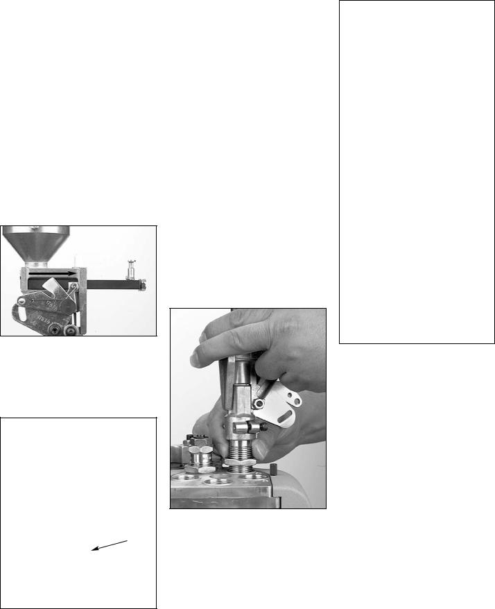
Before placing the casefeed bowl on the casefeed post, take a moment to look over and understand the casefeed assembly and how it works. If you like, you can run the casefeeder before placing it on top of the casefeed post. This will allow you to get a better idea of how it works. To do so, plug in the casefeeder and fill it with about 50 cases. Hold the casefeeder FIG 19 so the funnel is vertical. Place the cartridge bin under the funnel and turn it on. Experi-ment using both the high and low settings.
FIG 19 |
FIG 22 |
|
4. Place the casefeed adapter on the case- |
|
|
|
feed body FIG 22. Note how the key |
|
fits into the notch on the casefeed |
|
body. |
|
Note: Casefeed adapters are caliber spe- |
|
cific. Crosscheck your casefeed |
|
adapter with the one listed in the |
|
caliber conversion chart (for the cal- |
|
iber you’re loading) to ensure that |
|
you have the correct one installed in |
|
your machine. |
|
|
FIG 20
2.Remove the set screw from the accessory bag and thread it into the casefeed assembly FIG 20.
FIG 21
3.Place the casefeed bowl onto the casefeed post FIG 21.
FIG 23
5.Align the casefeed bowl so the spring clamp is directly over the casefeed adapter. Place the casefeed tube into the casefeed adapter then snap the tube into the clamp FIG 23.
10

Note: One end of the casefeed tube is beveled and one end is squared off. Insert the squared end of the tube (down) into the top of the casefeed adapter.
FIG 24
6.Using A 5/32” Allen wrench, snug the machine screw against the casefeed mounting post FIG 24 to prevent the casefeed bowl from rotating.
4.Toolhead Overview
You’re now ready to install the toolhead and adjust the dies. But first, we’ll give a brief overview of the location and function of each station, we’ll then follow up with a detailed illustration.
Station 2 - Powder Measure
FIG 26
Station 2 is for the powder die, which comes attached to the powder measure FIG 26. Here several operations are conducted. The case is primed, straightwalled pistol cases are belled, and powder is dropped. The purpose of the bell at the mouth of the case is simply to help align the bullet and to keep the case from shaving lead during the seating process. Note: Only straight-walled cases receive a bell, bottle-necked cases (rifle cartridges) are not belled.
Station 5 - Crimp
Station 5 is for the crimp die FIG 25. This die not only removes the bell created at Station 2, but rolls the mouth of the case inward to insure proper feeding and to secure the bullet.
LUBRICATING BRASS
To lubricate brass, use “Dillon Case Lubricant” (item# 13733).
Pistol – If you’re using a carbide sizing die, you will not need to lubricate your cases (before sizing) when loading straightwalled cases. If you’re not using a carbide sizing die, you must lube the brass before sizing. We do, however, recommend lubricating all brass.
Rifle – Lubricate all bottle-necked cases, even if you’re using a carbide sizing die.
To lubricate your cases, start by ensuring that they are clean. Place your clean brass in a shallow box so the cases are laying on their side. Pump a couple of sprays of Dillon Case Lubricant over the cases. Shake the box so the cases will tumble and roll. Repeat this process again making sure that the lubricant is well distributed over the cases.
Note: When loading rifle cartridges, if your sizing die doesn’t have a carbide
case mouth expander, you may
want to allow a little bit of lube to get inside the case mouth.
Note: When loading bottle-necked cartridges, if you get an excessive amount of lube on the shoulder of the case, it will leave oil dents. Regardless of whether you’re lubri cating pistol or rifle cases – do not drench the cases in lubricant. A light film of lubricant is sufficient.
Toolhead Head Setup:
Pistol – go to page 12
Rifle – go to page 20
FIG 25
Station 1 - Sizing/Decapping
The stations on the toolhead are numbered 1-5. Station 1 is for the sizing/decapping die FIG 25. This die can be easily identified by the decapping pin sticking out the bottom as well as by its label. This die removes or “decaps” the old primer and resizes the case.
Warning: Never decap live primers! (See mandatory safety procedures.)
FIG 27
Station 3 - Powder Check
Station 3 is used for the optional powder check system FIG 27. This system is located in a separate package and can be identified by the blue warning buzzer attached to a die. This system is designed to detect gross deviations in the powder charge, i.e. a double charge of powder or no powder at all.
Station 4 - Bullet Seating
Station 4 is for the seating die FIG 25. This is where the bullet is pushed into the case.
11
PISTOL SECTION –
Toolhead Set Up
To set up the toolhead you’ll need to have empty brass, bullets, primers and powder on hand. (For your convenience Dillon Precision offers a wide variety of new primed and unprimed brass, bullets, primers and powder.) For easy access, place your brass in an open container. Dillon Precision also offers a variety of blue bin boxes which come in handy for this purpose.
Note: Also, when priming, pushing the handle against its full aft stop, FIG 28, will insure that the primer is fully seated.
6.Again, raise the platform. The case is now sized. If the case has a spent primer, it will be deprimed. Leave the platform in the raised position with the case fully inserted in the die. This will ensure that the die remains in alignment when tightening the lockring.
A. Station 1 – To install the size/decap die FIG 25:
Warning: Never attempt to de-prime live primers, an explosion may result in serious injury or even death.
1.Raise the platform, by lowering the handle all the way down.
2.Screw the sizing die into Station 1. Continue to screw the die down until it just touches the shellplate. Tighten the die lockring finger tight Now lower the platform by raising the handle to its upright position.
3.Place a case in the casefeed funnel. Here, the case drops to the casefeed arm bushing.
4.Raise the platform. The inserter cam pushes the feed arm bushing over the body, dropping the case onto the Station 1 locator.
5.Lower the platform. The case is inserted into Station 1.
FIG 28
Note: After raising the handle, insure that you push the handle against its full aft stop FIG 28. This will insure
that the case is fully inserted into Station 1.
FIG 29
7.Using a 1-1/8” wrench to turn the lockring and a 7/8” wrench to hold the die body, tighten the lockring
FIG 29.
FIG 30
B.Station 1 – The decapping assembly FIG 30:
Dillon decapping assemblies are made with replaceable decap pins. One extra pin is included with each sizing die. To replace a bent or broken pin, simply:
1.Unscrew the decapping assembly from the top of the die FIG 30.
A
B
FIG 31
2.Unscrew the knurled retaining nut, see “A” FIG 31, remove the old pin and replace it with a new one, see “B” FIG 31.
3.Screw the decapping assembly back into the sizing die.
Note: The decapping assembly can be removed from the sizing die without affecting the adjustment of the sizing die or sizing operation.
Note: The decapping assembly must be removed when loading primed cases. (Tip: Check prices of components. You can often purchase primed cases for the price of the primers and new empty cases. Obviously, this is a good deal since you pay the same price and save time.)
FIG 32
C.Station 2 – Installation of powder measure assembly FIG 32:
12

FIG 36
3.Remove the powder funnel FIG 36 from the bag containing the locator buttons.
type. The bottom of the rifle-style funnel fits snugly over the neck of the case, allowing powder to drop in without spilling (the rifle-style powder funnel does not bell the mouth of the case). The bottom of the pistol funnel, on the other hand, fits inside and actually expands and bells as it guides the powder into the case. Powder funnels are caliber specific, so be sure you have the correct funnel by referring to the caliber conversion chart.
4.Insert the funnel into the die FIG 38. Make sure that you insert the funnel into the die with the grooved end up. The funnel should move up and down freely.
FIG 33
FIG 34
1.Use a 5/32” Allen wrench to loosen the two collar clamp screws and remove the powder die FIG 33 & 34.
FIG 35
2.Screw the powder die into Station 2. Stop when the die is flush with the bottom of the toolhead FIG 35.
FIG 37
FIG 38
About Powder Funnels:
In FIG 37 are two examples of the many powder funnels available for the XL 650. On the left is a typical pistol caliber funnel. On the right, a rifle or bottle-necked
FIG 39
5.Remove the lid and the protective cardboard tube from the powder measure and place it onto the powder die FIG 39. Turn down the two clamp screws until they are snug. Then loosen them slightly. The measure should move freely atop the die.
D.Station 2: About Powder Bars
Dillon Precision manufactures four types of powder bars for the XL 650:
1.Extra Small – use for dropping less than 3 grains of powder.
2.Small – use for dropping 3 to 20 grains of powder.
3.Large – use for dropping 20 to approx. 45-50 grains of powder.
4.Magnum – use for dropping more than approx. 45-50 grains of powder.
The extra small powder bar is used when loading .32 Auto, .32 S&W and .32 SWL. Both the extra small powder bar and the magnum powder bar are non-standard items and are ordered separately. The large and small powder bar, on the other hand,
13
are standard equipment and are included with every XL 650. If you ordered your machine set up for a specific caliber, the proper size powder bar should already be installed. If you need to change the powder bar – refer to “Powder Bar Adjustment” in the Caliber Conversion Section on page 30.
E. Station 2 – Adjustment of Powder Die & Powder Funnel:
Note: Adjusting the powder die for a straight wall case is not the same as adjusting a powder die for a bottle-necked case. This is because straight wall cases are given a bell and bottle-necked cases are not given a bell. Adjusting the powder die for a bottle-necked case is covered in the rifle section.
FIG 40
For the powder bar to properly dispense a measured powder charge the powder bar must travel its full distance. To travel its full distance, the white cube must contact the powder measure body (see arrow FIG 40).
FIG 41
Also the belling process does not begin until after the powder bar has traveled its full distance. The angled portion on the bottom of
the powder funnel (see arrow FIG 41) is what bells the cartridge. Once the white cube has contacted the powder measure body the case is forced upward against the tapered portion of the powder funnel producing a bell. The more the powder die is adjusted down (clockwise) the more the case will be belled.
Note: If the powder die is not adjusted down far enough to cause the powder bar to travel its full distance the powder charge will be erratic and the case will not receive enough bell.
To adjust the powder die/powder funnel:
1.Drop a case into the casefeed funnel and cycle the handle. The case should now be in the shellplate at Station 1.
2.Raise the platform. Notice the resistance at the end of the downstroke. This is the resistance of the case in the sizing die. Lower the platform.
The case will index to Station 2.
3.Raise the platform. Check to see how far the powder bar has traveled
FIG 40.
FIG 42
4.If the white cube has not traveled its full distance, lower the platform just enough to pull the case off of the powder funnel (this will prevent the shellplate from indexing while you adjust the powder die). While holding the powder measure, turn the die down 1/8 of a turn FIG 42. Again raise the platform and observe the travel of the powder bar.
5.Repeat step four until the powder bar travels its full distance FIG 40.
A
Correct amount of bell.
B
Not enough bell.
C
Too much bell.
FIG 43
Once the powder bar travels fully across you should continue to adjust the powder die for the desired amount of bell (turn the powder die 1/8 of a turn at a time). The desired amount bell is just enough to allow the bullet to sit on the case mouth without falling off and to keep the case from shaving lead during the seating process (see “A” FIG 43).
Note: If you screw the die down too far, the case will look like example “C” FIG 43. You must then discard
this case, back the powder die off, by turning it counter-clockwise, and continue with a new sized case.
You’ll soon learn to judge the correct amount of bell by simply looking at it. In the meantime, you might want to use your dial calipers to check it. Twenty thousandths of an inch greater (at the mouth of the case) than its original diameter, should about do it.
14

FIG 44
6.Once you’ve achieved the desired amount of bell – with the case in Station 2, raise the platform. Run the lockring down hand tight FIG 44.
FIG 45
FIG 46
7.Insure the bellcrank and the failsafe bracket FIG 45 are aligned. Using a 5/32” Allen wrench, snug the collar clamp screws FIG 46.
FIG 47
8.While holding the powder measure, snug the lockring using a 1 1/8 wrench FIG 47. Now lower the platform.
FIG 48
F.Station 2 – Installation of the failsafe rod assembly FIG 48:
The purpose of the powder measure failsafe rod is to return the powder bar to its recharge position.
FIG 49
1.Using your forefinger, move the locklink (#17838) down to align the hole with the slot on the Powder Measure bellcrank (#97034) FIG 49.
FIG 50
2.Insert the rod (#13629) through the holes FIG 50.
3.Loosen the blue plastic wing nut (#13799).
FIG 51
4.Slide the failsafe rod into the failsafe return bracket. Push the shoulder washer up into place (see arrow FIG 51) and tighten the blue plastic wing nut until the spring just touches the underside of the bracket.
Note: Do not fill the powder measure or adjust the powder bar until the rest of the dies are installed and adjusted.
15

FIG 52
G.Station 3 – Installation of the Powder Check System
FIG 52:
Note: The powder check system does not guarantee the accuracy of the powder charge. It is designed to warn you if the powder charge is grossly out of tolerance, i.e., no powder or a double charge.
Warning: A double-charged round (a loaded round with twice as much powder as it should have) can damage your gun as well as cause bodily injury.
Warning: A round loaded without powder can also damage your gun as well as cause bodily injury. If a round without powder is fired in your gun, the detonation of the primer will push the bullet part way down the barrel. If the lodged bullet is not removed before another round is fired, the gun will be damaged
and bodily injury may occur.
FIG 53
1.Loosen the die clamp screw FIG 53 and remove the die.
FIG 54
2.Raise the platform and screw the powder check die into Station 3. There should be a 1/8 to 1/4 inch space between the shellplate and the bottom of the die FIG 54.
FIG 55
3.Run the lockring down. Using a 1 1/8” wrench snug the lockring
FIG 55.
FIG 56
FIG 57
4.Remove the 10-24 screw and nut from the black push rod FIG 56 and place the powder check system on the powder check die FIG 57. Center the black push rod (see arrow FIG 57) in the hole that is to the left of the die.
FIG 58
5.Reinstall and snug the die clamp screw
FIG 58.
FIG 59
16
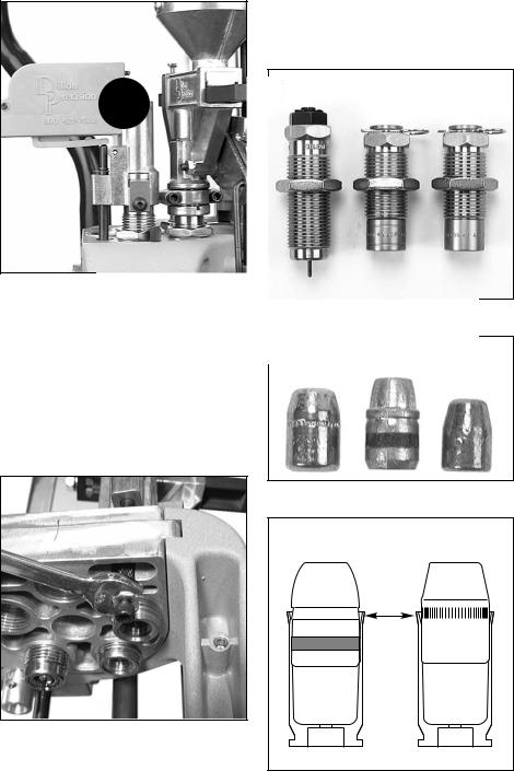
FIG 60
6.FIG 59 Screw the 10-24 screw and nut fully into the rod. Raise the platform. Unscrew the 10-24 screw until it contacts the edge of the platform FIG 59. Lower the platform part way and unscrew the screw (counterclockwise) until raising the platform causes the buzzer housing to gently rock into the side of the die collar
FIG 60.
H.Station 4 – General Information on Bullet Seating
Sizing/Decapping Die
Seating Die Crimp Die
FIG 62
A B C
you’re using doesn’t have a cannelure or a crimping groove (item C in FIG 63), then you’ll need to refer to your reloading manual for the suggested OAL. The purpose of the cannelure and crimping groove is to secure the bullet by giving the mouth of the case a place to go (without deforming the bullet) when being crimped. When the bullet is properly seated, the mouth of the cartridge case should be near the top of the cannelure/crimping groove FIG 64.
Refer to your reloading manual. Under the section specified for the caliber you’re loading, you’ll find a schematic of the cartridge. For example, .38 Special lists a maximum OAL of 1.55” (Lyman Reloading Handbook). If you’re seating the bullet to the cannelure/crimping groove, the OAL should be well within the maximum OAL listed, however, use a set of dial calipers to check it. (Dial calipers are available from Dillon Precision). If the bullet you’re using doesn’t have a cannelure/crimping groove, refer to the specific type of bullet you’re using in the reloading manual. For example
– if you’re loading a 158gr 38sp JHP and it doesn’t have a cannelure/ crimping groove, use the suggested OAL of 1.480 (Lyman Reloading Handbook).
FIG 61
7.Secure the jam nut by holding the black push rod while tightening it using a 3/8” wrench FIG 61.
Note: Once you’ve adjusted the powder bar for the desired powder charge, adjustment of the powder check system can be completed.
FIG 63
FIG 64
The purpose of the seating die FIG 62 is to insert the bullet into the case and to push it down into the case the proper amount.
How far the bullet is pushed into the case will determine the overall length (OAL). Several factors go into determining the proper OAL – such as, the maximum recommended OAL, listed in the reloading manual, and the type of bullet being loaded. The type of bullet can determine the OAL in one of two ways. If the bullet has what is called a cannelure, or crimping groove (items A&B in FIG 63), this will determine the proper OAL. If the bullet
17

FIG 65
I.Station 4 – Seating Stems for pistol FIG 65
All pistol seating dies come with interchangeable seating stems. The seating stem you should use will depend on the shape of the bullet you’re loading. Three different types of seating stems may be available – wadcutter, semi-wadcutter and round nose. Check to make sure that the seating stem installed in your seating die matches the bullet you are loading.
Dillon seating dies, which are being used in this manual, are easily disassembled. Simply remove the hitch pin from the top and slide the seating stem out FIG 65. Replace the seating stem and reassemble the die.
J.Station 4 – Installation and Adjustment of the
Seating Die:
1.Take the seating die from the die box and screw it into Station 4. Screw the die down until the bottom of the die is flush with the bottom of the toolhead FIG 66. Note: At this point the die will not be screwed down far enough to begin seating the bullet, but it will give you a place to start.
2.Place a case (with a belled case mouth) into Station 4.
3.Place a bullet on the belled case mouth and raise the platform. Then, lower the platform just enough to inspect the bullet without indexing the shellplate. If the bullet is not seated deep enough, screw the seating die down 1/2 turn at a time. As a guide, one full turn moves the die down about 70 thousandths of an inch, about the thickness of a nickel. Again, cycle the machine and inspect the seating depth. Repeat these steps as necessary until the correct overall length is achieved. Use a dial caliper or equivalent to measure the overall length of the cartridge. Check the overall length of the round against the information in your reloading manual.
FIG 67
4.Once you have obtained the proper OAL, replace the cartridge into Station 4 and raise the platform. Using a 1-1/8” wrench to turn the lockring and a 7/8” wrench to hold the die body, snug the lockring
FIG 67.
Note: If you should happen to seat the FIG 66 bullet too deep, you can use a
Dillon bullet puller to reclaim your components.
Sizing/Decapping Die
Seating Die Crimp Die
FIG 68
K.Station 5 – Installation and adjustment of the Crimp Die FIG 68:
1.Screw the crimp die into Station 5. Screw it down until it is flush with the bottom of the toolhead. This is a good starting point for the crimp adjustment.
2.Place a cartridge with a properly seated bullet into Station 5.
FIG 69
3.Raise the platform and continue to screw the die down until it touches the cartridge FIG 69.
4.Lower the platform and give the die an 1/8 turn down, again raise the platform.
5.Lower the platform halfway and inspect the cartridge. If the bell is still present, or the desired amount of crimp has not been achieved, give the die a 1/8 turn down and try again. Continue making small adjustments to your crimp die until the desired amount of crimp has been achieved.
6.Once the adjustment is complete, place the case back into Station 5 and raise the platform. Using a 1-1/8” wrench to turn the lockring and a 7/8” wrench to hold the die body, snug the lockring.
18

|
1 |
|
2 |
|
|
3 |
|
|
|||||
|
|
|
|
|
|
|
|
|
|
|
|
|
|
|
|
|
|
|
|
|
|
|
|
|
|
|
|
|
|
|
|
|
|
|
|
|
|
|
|
|
|
|
|
|
|
|
|
|
|
|
|
|
|
|
|
|
|
|
|
|
|
|
|
|
|
|
|
|
|
|
|
|
|
|
|
|
|
|
|
|
|
|
|
|
|
|
|
|
|
|
|
|
|
|
|
|
|
|
|
|
|
|
|
|
|
|
|
|
|
|
|
|
|
|
|
|
|
|
|
|
|
|
|
|
|
|
|
|
|
|
|
|
|
|
|
|
|
|
|
FIG 70
Note: FIG 70 When adjusting the crimp die it is important to know what to look for. Check that the crimp: Looks OK, allows your firearm to function consistently and the bullet feels tight in the case.
The drawing of case #3 FIG 70 is a depiction of a case that has been over crimped by adjusting the crimp die down (clockwise) too far. Note the defined line below the mouth of the case and the bulge below the line. This is not a proper crimp. This line is the direct result of the cartridge being over crimped. A line like this will only appear if the crimp die is adjusted down too far. Warning: Over crimping
.45ACP, .38 Super, 9mm, etc., can actually cause the bullet to be loose in the case.
Go to Loading Components Section – Page 30
19
 Loading...