


FI-127 Force Indicator
User’s Manual

CAUTION
Risk of electrical shock. Do not remove cover. No user serviceable parts inside. Refer servicing to qualified service personnel.
Weigh-Tronix reserves the right to change specifications at any time.
06/30/98 FI127USE.P65 PN 29653-0017B Printed in USA
2

Table of Contents
Introduction ............................................................................................................................................................................... |
5 |
Operating Modes ...................................................................................................................................................................... |
5 |
Front Panel ................................................................................................................................................................................. |
6 |
Keys6 |
|
Standard Instrument Keys ................................................................................................................................... |
6 |
Function Keys ......................................................................................................................................................... |
6 |
Keypad Keys ............................................................................................................................................................ |
7 |
Directional Keys ..................................................................................................................................................... |
7 |
Annunciators .................................................................................................................................................................... |
7 |
Error Messages ......................................................................................................................................................................... |
8 |
Using Your FI-127 .................................................................................................................................................................... |
9 |
Setting Up Your FI-127 .................................................................................................................................................. |
9 |
Performing a Force Measurement .............................................................................................................................. |
9 |
Using the Function Keys.............................................................................................................................................. |
10 |
F1 Key ..................................................................................................................................................................... |
10 |
F2 Key ..................................................................................................................................................................... |
11 |
F3 Key ..................................................................................................................................................................... |
11 |
Using the User Menu ............................................................................................................................................................ |
12 |
The User Menu.............................................................................................................................................................. |
12 |
Capture .................................................................................................................................................................. |
12 |
Hour ........................................................................................................................................................................ |
14 |
Day .......................................................................................................................................................................... |
14 |
Database ................................................................................................................................................................. |
15 |
Loadcell ................................................................................................................................................................... |
16 |
Bounds .................................................................................................................................................................... |
17 |
Using the Service Menu ........................................................................................................................................................ |
18 |
About Menu ................................................................................................................................................................... |
18 |
Audit Menu ..................................................................................................................................................................... |
19 |
Abuse Menu .................................................................................................................................................................... |
20 |
Zero Menu ...................................................................................................................................................................... |
20 |
Test Menu ....................................................................................................................................................................... |
21 |
Setup Menu ..................................................................................................................................................................... |
24 |
Units submenu ...................................................................................................................................................... |
24 |
Loadcells submenu ............................................................................................................................................... |
26 |
Options submenu ................................................................................................................................................ |
32 |
Serial submenu...................................................................................................................................................... |
41 |
B.C.D. Out submenu .......................................................................................................................................... |
42 |
Analog submenu ................................................................................................................................................... |
42 |
Outputs submenu ................................................................................................................................................ |
43 |
Inputs submenu .................................................................................................................................................... |
44 |
Seal submenu ........................................................................................................................................................ |
44 |
Reset Menu / Master Clear ................................................................................................................................................ |
47 |
Adding and Calibrating a Loadcell ...................................................................................................................................... |
48 |
Adding a Loadcell .......................................................................................................................................................... |
48 |
Calibrating a Loadcell ................................................................................................................................................... |
49 |
Step by Step Instructions...................................................................................................................................................... |
52 |
Strings .............................................................................................................................................................................. |
52 |
Layouts ............................................................................................................................................................................. |
54 |
Groups ............................................................................................................................................................................. |
56 |
Freeze Force Function .......................................................................................................................................................... |
58 |
Control ............................................................................................................................................................................ |
58 |
Display.............................................................................................................................................................................. |
58 |
Keypad ............................................................................................................................................................................. |
58 |
Outputs ........................................................................................................................................................................... |
58 |
Data Capture ........................................................................................................................................................................... |
59 |
Control ............................................................................................................................................................................ |
59 |
Display.............................................................................................................................................................................. |
59 |
Keypad ............................................................................................................................................................................. |
59 |
Outputs ........................................................................................................................................................................... |
59 |
Notes ............................................................................................................................................................................... |
59 |
Appendix A: ASCII Control Codes ................................................................................................................................. |
60 |
Appendix B: Default Layouts and Examples ................................................................................................................. |
61 |
Appendix C: Tips on Setting Up and Using the Harmonizer® ................................................................................. |
63 |
Appendix D: Cable Pinouts ............................................................................................................................................... |
64 |
3

FI-127 Specifications
Power requirements:
115 Volts AC, +10% to -15% @ 0.3Amp maximum 230 Volts AC, +10% to -15% @ 0.15 AMP maximum 50 /60 Hz
Excitation: 10 Volts DC
Supports up to twelve 350-ohm weight sensors
Operational keys:
Five yellow standard keys: Select, Peak Reset, Data Send, Zero, Units
Three function keys: F1, F2, F3
Numeric keys: 0-9
Operational annunciators:
Tension, Compression, Under, Accept, Over, Print, Zero,
and Motion
Three units of measure
Display: Eight digit, seven segment, 0. 8-inch high LED
Display rate: Selectable (1, 2, 5, 10)
Analog to digital conversion rate: 60 times per second
Calibration Memory: Six loadcell calibration memory
Unit of measure:
Three, independently programmable:
Pounds force, kilograms force, grams force, ounces force, ton force, tonne force, custom, Off
Capacity selections:
999,999 with decimal located from zero to five places
Incremental selections:
Multiples and submultiples of 1, 2, 5
Programmable selections:
Zero range, motion detection, five-point linearization.
Time and date /RAM:
Battery backed up real time clock and RAM are standard
Internal resolution: 6,291,456 counts per mV/V per sec.
HarmonizerTM digital filtering:
Fully programmable to ignore noise and vibration
Standard inputs:
Seven logic level inputs for functions such as foot switch inputs, freeze reading inputs, PLC control, etc.
Standard outputs:
Three outputs, open collector design
Relay power supply, 24 VDC at 150mA
5 VDC at 200 mA for scanner power source Bidirectional serial port (RS-232 or RS-422/485 or
20mA current loop)
Self diagnostics:
Display, keys, inputs, outputs, serial port,
A to D converter, loadcell output display, voltages
Circuitry protection: RFI, EMI, and ESD protection
Options:
Two additional serial ports
BCD parallel
10 cutoffs Analog output
0-5, 0-10 volts
1-5, 4-20, 10-50 mA
Operating temperature:
-40 to 140° F (-40 to 60° C)
100% relative humidity including washdown
Enclosure: NEMA 4X stainless steel enclosure
Dimensions:
12" W x 8" H x 4" D (without mounting bracket) 12.3" W x 11.0" H x 5.3" D (with mounting bracket)
Weight: 12.5 lb, 5.7 kg
Agencies:
CUL pending
Warranty: 2 year
4

Introduction
Major sections of this manual are separated by the large black bars as seen above and below. Subsections are titled in this lefthand column. Notes, definitions, and other information also appear in this column
The model FI-127 is a versatile, full-featured indicator housed in a stainless steel enclosure. Its user interface includes an 8-digit, 7-segment LED display, fourteen LED annunciators, and 24 keys.
This manual is divided into the following major sections:
•Introduction
•Operating Modes
•Front Panel
•Error Messages
•Using Your FI-127
•Using the User Menu
•Using the Service Menu
•Reset Menu/Master Clear
•Adding and Calibrating a Loadcell
•Step by Step Instructions
•Freeze Force Function
•Data Capture
Operating Modes
There are three modes of operation for the FI-127—Display mode, User Menu mode and Service Menu mode.
In Display mode you perform all normal force measurement operations.
The User and Service menus give you access to testing modes, configuration of your system, database and system information. This manual explains how to use these different modes of operation.
5
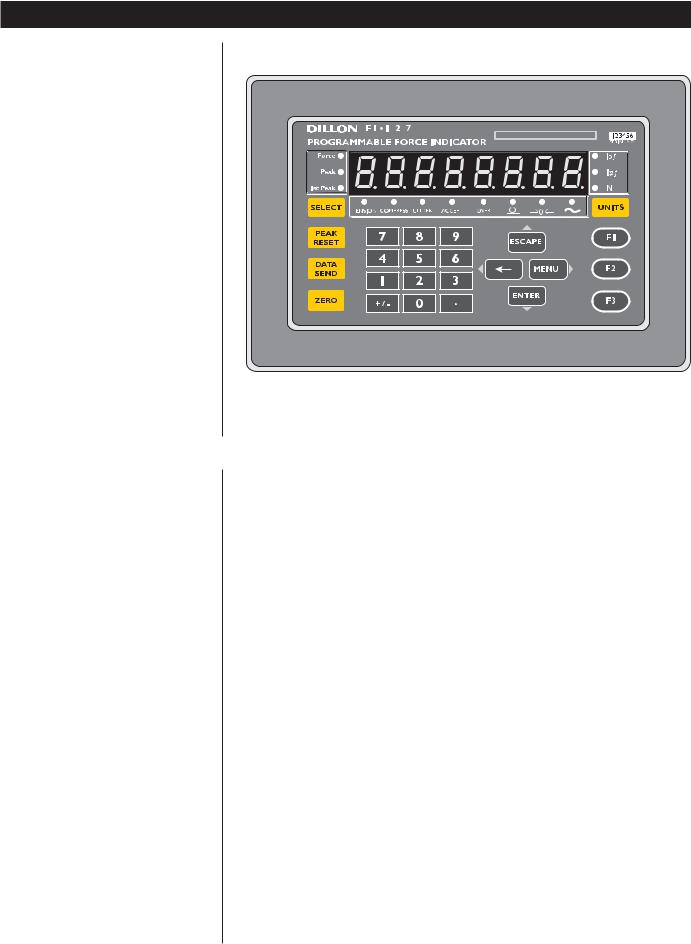
Front Panel
The FI-127's front panel consists of 24 keys and fourteen annunciators.
Figure 1
FI-127 Front Panel
Keys |
The FI-127's keys are divided into four primary groups: |
Standard Instrument Keys
Standard Instrument Keys These yellow keys are common to a majority of applications and include SELECT, PEAK RESET, DATA SEND, ZERO, and UNITS. The SELECT and UNITS keys are placed next to the annunciators they affect.
SELECT |
Use to switch between force, peak ad first peak display modes. |
|
SELECT can also be used to accept a current selection and |
|
return to weigh mode from within any menu. |
PEAK RESET |
Use to reset all peak and first peak values. This key may also be |
|
used to capture the current measurement as an entered value |
|
during data entry. |
DATA SEND |
Use to initiate one or more serial outputs. |
ZERO |
Zeros the scale in the display mode. Also clears values in |
|
numeric entry. |
UNITS |
Switches the units of measure in the display mode. Up to three |
|
units of measure are selectable. |
Function Keys
Function Keys These oval keys along the right side of the display face are configurable and are labeled F1, F2, and F3. The default configurations for these keys are:
F1 Allows load cell selection
F2 Allows entry of ID number
F3 Allows access to cutoff registers.
6

Keypad Keys
Directional Keys
Keypad Keys These are the twelve square keys which support numeric entry. The keyboard keys are labelled 0-9, plus/minus (+/-), and decimal point (.) and are located near the center of the display face.
+/- This key is used to change the sign of a numeric entry, enter a dash in ID entry, and insert when editing lists. This key also initiates numeric entry, except in display mode where it serves to toggle between tension and compression for bidirectional cells. Toggling between tension and compression resets peak, first peak and break detect; unfreezes the force display; and halts data capture.
Directional Keys The directional keys are used to navigate through the FI-127's menus. These keys are labeled ESCAPE (up), ENTER (down), ← (left), and
MENU (right) and are positioned in a compass-like cluster on the display face. These directional keys are denoted by the small transparent arrows located next to them. ESCAPE, ENTER, and ← also support numeric entry.
ESCAPE Exits a menu parameter without saving any changes. This key moves up within a menu. In display mode, ESCAPE "unfreezes" the force display.
ENTER Used to end digit entry, accept a change made, or select an item from a function list. ENTER moves down within a menu. When in display mode, ENTER "unfreezes" the force display.
ÅBackspaces (deletes the last digit or punctuation mark entered) while in numeric entry and moves left within a menu.
MENU Accesses user menus and moves right within a menu.
Annunciators
The FI-127 has fourteen annunciators.
Force |
Illuminates when indicator is in force display mode. |
|||||
Peak |
Illuminates when indicator is in peak display mode. |
|||||
1st Peak |
Illuminates when indicator is in first peak display mode. |
|||||
lbf, kgf, N |
Illuminates the active unit of measure in weighing mode. |
|||||
|
|
|
|
|
|
Data Send: Illuminates when the indicator is transmitting data. |
|
|
|
|
|
|
Does not illuminate when a host connection is communicating |
|
|
|
|
|
|
with the indicator or with continuous send. |
|
|
|
|
|
|
Zero: Illuminates when the scale is within the configured center |
|
|
|
|
|
|
|
|
|
|
|
|
|
of zero. |
|
|
|
|
|
|
Motion: Illuminates when the scale detects motion (within |
|
|
|
|
|
|
configured motion window). |
Under, Accept, Over Specific application annunciators.
Tension Indicates the type of force being measured.
Compression Indicates the type of force being measured.
7
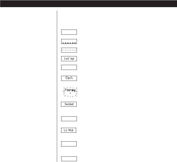
Error Messages
The following are displays you may see if problems occur or if invalid operations
are attempted with your FI-127:
Display Description
O. LoAd Overrange force.
Underrange force.
Recovering from lock-up or out of range condition.
A-D converter is not functioning.
L.C. Error A-D converter subjected to an input signal beyond ±5.00000 mV/V
Auto. 0
1 Busy
Ouch 
The unit cannot perform a function. Displayed only while key is held down.
Corrupted data in the reset menus. See the Service Manual. (* = RESET, SETUP, or CAL)
Displayed while a key is pressed when attempting to modify a sealed selection without edit privileges.
Displayed while waiting for a stable, valid weight to use as a zero reference on power-up.
Displayed when input voltage to excitation regulator drops below 10.5 VDC. Will clear when input voltage rises above 11.5 VDC.
Displayed when the ready/busy handshake has exceeded its time out limit. Default is 2 seconds. This can also apply to optional 2nd and 3rd serial ports.
Displayed when the force applied to the load cell has exceeded the level considered to be abusive to the load cell.
8

UsingYour FI-127
Setting Up Your FI-127
Your FI-127 will probably be ready to use when you receive it from your Dillon distributor. Connect the loadcell to the 7-pin connector on the back of the unit. Connect your RS-232 communication equipment to the other connector on back of the FI-127. Power up your peripheral equipment and plug in the FI-127 to an appropriate grounded power source.
The indicator will power up in Display mode with annunciators lit for your application. From the factory, the default annunciators which are lit are Force, Tension and lb F. The center of zero (COZ) annunciator should also be lit. If the display does not show 0 or the COZ annunciator is not lit, press the ZERO key.
Your unit is now ready for use in your force measurement application. If you want to add a loadcell, see the section Adding a Loadcell later in this manual.
Performing a Force
Measurement
First Peak
First peak is defined as an applied force, followed by a drop in force of at least x% of full capacity followed by an ultimate peak in force. x is called the capture percentage. You can set this percentage via the front panel. Instructions can be found in the section Using the Service Menu. See the graphed example in Figure 2.
1.With the indicator powered up, select the unit of measure you want to use by pressing the
UNITS key. . .
2.Press the ZERO key if the display does not show 0 and apply force to the loadcell. . .
3.If you are running a test where First Peak and Peak readings are important to you, you can see those values by pressing the
SELECT key. The value on the display will correspond to the annunciated item on the left side of the display panel. See the First Peak definition at left.
4.After you have seen the peak values, you can reset them by removing the force from the loadcell and pressing the PEAK RESET key.
5.Repeat steps 2-4 for the other force measurements you want to make.
The proper annunciator will light.
The force will be displayed in the unit
of measure you have chosen. The type
of force, tension or compression, will
be indicated by the annunciators under
the display. The motion annunciator
will be lit while the indicator detects
motion.
9

Using the Function Keys
F1 Key
10
Full Scale Capacity of Loadcell |
Time
Figure 2
First peak illustration
The function keys are used for
•F1 Loadcell selection
•F2 ID number entry
•F3 Viewing or entering data in cutoff registers
1. Press F1 key. . . |
The display shows the current cell |
|
number and a letter showing if the cell |
|
type is F for force or T for torque. |
2.Press the ENTER key. . .
3.Press the MENU key. . .
4.Press the ENTER key to return to Display mode or press
the ESCAPE key to return to the display from step 1.
The capacity of the current cell is displayed.
The division size for the current cell is displayed.
F2 Key
F3 Key
Cutoff Register
A cutoff register is a force value you enter into memory (register) which the indicator uses to control outputs. There are 10 cutoff registers in the FI-127. You can set ten different force values which the indicator will use to trigger outputs.
When activated (force on the loadcell is less than the force in the cutoff registers), these cutoffs are all on at the same time. Each cutoff will deactivate as soon as the force on the loadcell matches the value in each cutoff register.
When the force is equal to or greater than positive register values, or more negative than negative register values, the corresponding output is disabled.
When the force is less than the positive register values, or less negative than negative register values, the corresponding output is enabled.
1.Press the F2 key. . .
2.Press any of the following keys to return to Display mode:
F2, Å, MENU, ESCAPE,
SELECT
or
The current ID number is displayed.
press a number key to start entering a new ID number. When you are finished, press the ENTER
key. . . The new number will become the active ID number.
The F3 key is used to view and change cutoff registers. You can view cutoff registers by two methods:
Method A:
1.Press the F3 key. . .
2.Continue pressing F3 or MENU to scroll forward or Å to scroll
backward through the remaining cutoff registers.
Method B:
1.If you know which cutoff register you wish to view, press the number of that register, then press
F3. That particular cutoff register is displayed.
1 xx is displayed. The number 1 stands for cutoff register #1 and xx is the current value in register 1.
To change a cutoff value, display the register you want to change then:
1.Key in a new value with the numeric keypad. Use the +/- key to change the sign of the value.
Press the ENTER key to accept the new value and return to
Display mode
or
press the F3 key to accept the new value and move to the next register.
2.To deactivate or clear a cutoff value, set the value to zero.
11
Using the User Menu
Use these keys to navigate through the menus:
ESCAPE = up ENTER = down
Å = left MENU = right
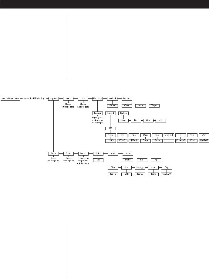
The FI-127 has two menus—the user menu and the service menu. The service menu is covered later in this manual. You use it to configure the operation of your indicator. The user menu, shown in Figure 3, allows you to do the following things:
•Capture and view data points
•Print a report on data points
•View statistics about captured data points
•Delete captured data points
•View the current time and date
•View and delete database records
•See live display of loadcell output in counts or mV/V
•Set Target, Under, and Over values
The User Menu
Capture
This manual assumes that all functions are enabled. Your indicator may not show some of the items in the user menu because your configuration does not enable them. See the Using the Service Menu section to reconfigure your system.
Figure 3
User menu
Following are instructions for accessing and using the user menu. Refer to Figure 3 as you go through these instructions.
1. |
Press the MENU key. . . |
CAPturE is displayed. This is the first |
|
|
menu item. Use this to start and stop |
|
|
capturing data points, view captured |
|
|
points, see statistics on captured points |
|
|
and to delete the points. |
2. |
Press the ENTER key. . . |
StArt or StoP is displayed depending |
|
|
on if you are currently capturing data |
|
|
points or not. |
12

Remember to use the direction keys to navigate among the levels and choices in the menu structure.
Press SELECT to accept the current selection and return to the Display mode from anywhere in the menus.
3.Press the ENTER key to start or stop capturing data points. . .
4.Press the MENU key to move to the next menu item. . .
5.Press the ENTER key with this displayed if you want a preconfigured set of information to be sent through the serial port.
The indicator will start or stop capturing data points.
rEPOrt is displayed. Use this to print a report on the data capture information.
6.Press the MENU key to move to the next menu item. . .
7.Press the ENTER key to view the current point number. Press Å or
MENU to scroll to other points. With the point you want displayed, press the ENTER key to see the value of that data point. . .
Point is displayed. Use this to see any captured data point.
The captured point will be displayed as well as the unit of measure and tension/ compression annunciators.
8.Press the MENU key to move to the next menu item. . .
9.Press ENTER to see the first item in the list of statistics. Press the Å or MENU to move to other stat. items and press ENTER to see the value for the displayed statistic. Following are the statistics and what they show you:
StAtS. is displayed. Under this item you can see statistics on the captured data points.
Top |
Peak value for the currently captured points. |
First |
Shows the first peak value for the currently captured points. |
Average |
Shows the mean value of the currently captured points. Does |
|
not include those points which are below the data capture |
|
threshold set in the Ave. Over parameter of the setup menu. |
|
See the Service Manual. |
Hour |
Time at which the data was captured. |
Day |
Date on which the data was captured. |
13

Use these keys to navigate through the menus:
ESCAPE = up ENTER = down
Å = left MENU = right
Hour
Day
10.After viewing the statistics, press the ESCAPE key until StAtS. is displayed, then press MENU to see the next menu item. . .
11.Press the ENTER key. . .
12.If there are data points to delete and you want to delete them, press
ENTER while All is displayed. . .
13.Press ESCAPE twice to return to the CAPturE display. Press MENU to move to the next user menu item. . .
14.Press ENTER to see the currently set time. . .
15.Press ENTER or ESCAPE to leave the time and format unchanged or enter a new time using the numeric keys.
16.After changes have been made to the time, press the ENTER key to accept them and start the clock. . .
17.Press the MENU key to go to the next menu item. . .
18.Press ENTER to see the currently set date. . .
19.Press ENTER to accept this date or key in a new date and press
ENTER to accept it. . .
dELEtE is displayed. Use this to delete all captured data points.
donE is displayed if there are no data point to delete. All is displayed if there are data points to delete.
The data points are deleted from memory and donE is displayed.
Hour is displayed.
Time is displayed as HH:MM:SS (24 hour clock) or HH:MM:SS AM (12 hour clock). You may toggle between the two formats by pressing the
UNITS key.
Display shows Hour.
dAY is displayed.
The date is displayed as MM/DD/YY.
dAY is displayed.
14

Database 20. Press the MENU key to go to the next menu item. . .
21. Press the ENTER key. . .
22.Press the ENTER key to send the database information to the serial port. . .
23.Press ENTER then MENU to go to the next menu item under dAtAbASE. . .
24.Press the ENTER key to access the current record. . .
25.You can view this record's data by pressing the ENTER key
or
you can access other record numbers by pressing the Å or
MENU key, then press the
ENTER key. . .
26.Use the Å or MENU key to scroll through the list of items, then press the ENTER key to view the value for each item,
dAtAbASE is displayed. Under this menu item you can send a preconfigured report of database items to a serial port, look at individual records in the database and delete one or all of the records.
rEPOrt is displayed. Use this to send a report to a serial port. The information sent depends on the configuration of your system. See the Service Manual for instructions.
The print annunciator will light then the display will show dAtAbASE again.
rEcord is displayed.
A record number is displayed.
The first item in the database record is displayed. What this item is depends on the configuration of your database.
15

Use these keys to navigate through the menus:
ESCAPE = up ENTER = down
Å = left MENU = right
Loadcell
Below is a full list of items in default order:
Force A stored force measurement. Displayed with unit of measure and tension/compression annunciators.
Top A stored peak value. Displayed with unit of measure and tension/ compression annunciators.
First A stored first peak value. Displayed with unit of measure and tension/compression annunciators.
Disp. A stored measurement. May be Force, Top or First depending on configuration. Press the ENTER key again to see the value. Displayed as F 1234.5 if the stored value is a frozen force. Displayed with unit of measure and tension/compression annunciators.
Sel. A stored measurement. May be Force, Top or First depending on configuration. Press the ENTER key again to see the value. Displayed with unit of measure and tension/compression annunciators.
Loadcell A stored loadcell number.
Id A stored ID number.
Hour Time the record was stored.
Day Date the record was stored.
27.Press ESCAPE until rEcord is displayed, then press the MENU key to move to the next item in the database submenu. . .
28, If you choose to delete one record you can scroll through the records using the Å or MENU keys then press the ENTER key to delete that one record. . .
29.With dELEtE displayed, press the
ESCAPE key. . .
30.Press the MENU key to move to the next user menu item. . .
31.Press the ENTER key to see a live display of loadcell output in either mV/V or counts. Toggle between the two views using the UNITS key.
dELEtE is displayed. Use the items under this to delete one or all the records.
dELEtE is displayed.
dATAbASE is displayed.
LOAdCELL is displayed.
16

Bounds
Target, Over, Under Example
Target value = 350 Under value = -10 Over value = 20
With these settings the ACCEPT annunciator will be lit when force is 340 to 370. The UNDER annunciator will be lit when force is less than 340. The OVER annunciator will be lit when force is greater than 370.
32.Press the ESCAPE key to return to the LOAdCELL display, then press MENU to move to the last user menu item. . .
boundS is displayed. Use this item to set target, over and under values. See example at left.
33. |
Press the ENTER key. . . |
OVEr is displayed. |
34. |
Press ENTER to see the current |
|
|
value. Key in a positive value then |
|
|
press ENTER to accept it. . . |
OVEr is displayed. |
35.Press MENU to display UndEr. Press ENTER to see the current value. Key in a negative value then
press ENTER to accept it. . . |
UndEr is displayed. |
36. Press MENU to display tArGEt. |
|
Press ENTER to see the current |
|
value. Key in a value then press |
|
ENTER to accept it. . . |
tArGEt is displayed. |
37.This is the last item in the user menu. Press ESCAPE repeatedly or SELECT to return to Display mode.
17

Using the Service Menu
Be sure to key in the password '127' before pressing and holding the ESCAPE key if you want to change items in the service menu, otherwise you will only be able to view them.
You use the service menu to see information about your indicator, to test its various functions and to configure how you want the system to work. Figures 4 through 19 show the service menu structure in the FI-127. Following each figure are explanations for each of the service menu items. Use the same methods to get around in the menu structure as you used in Using The User Menu section of this manual. To edit items in this menu you must key in '127' before pressing
and holding the ESCAPE key.
Figure 4
Top level of the Service menu
About Menu Information about the software
Audit Menu Audit counters for calibration and configuration
Abuse Menu Loadcell overload counters
Zero Menu Zero balance information and reset
Test Menu For testing the hardware of the indicator
Setup Menu For configuration of the indicator
About Menu
Figure 5
About menu
18

These are the items listed in the About menu:
127 |
The unit designation. |
12345 |
Parent part number of the software. |
-1234 |
The dash portion of the software part number. |
Rev. A |
The revision level of the software. |
Audit Menu
Figure 6
Audit menu
These are the items listed in the Audit menu:
Cal. 0000 This is an example of how the calibration audit trail counter will appear. The actual value will be between 0000 and 9999. It is nonresettable and may not be edited.
Cfg. 0000 This is an example of how the configuration audit trail counter will appear. The actual value will be between 0000 and 9999. It is nonresettable and may not be edited. The counter is incremented each time a metrological item is modified in the setup menus and saved and so may be used as a control audit.
19

Abuse Menu
Be sure to key in the password '127' before pressing and holding the ESCAPE key if you want to change items in the service menu, otherwise you will only be able to view them.
Cell 1 00
Figure 7
Abuse menu
This is an example of how a loadcell overload counter appears. Use the Å or MENU keys to view other loadcells you may have. The counter shows up to 99 overloads. An overload is defined as an applied force beyond the threshold configured under Abused in the loadcell configuration section of the service menu. The overload counter can only be reset at the factory.
Zero Menu |
This menu provides access to zero balance information and reset. |
||||||||||||||
|
|
|
|
|
|
|
|
|
|
|
|
|
|
|
|
|
|
|
|
|
|
|
|
|
|
|
|
|
|
|
|
|
|
|
|
|
|
|
|
|
|
|
|
|
|
|
|
|
|
|
|
|
|
|
|
|
|
|
|
|
|
|
|
|
|
|
|
|
|
|
|
|
|
|
|
|
|
|
|
|
|
|
|
|
|
|
|
|
|
|
|
|
|
|
|
|
|
|
|
|
|
|
|
|
|
|
|
|
|
|
|
|
|
|
|
|
|
|
|
|
|
|
|
|
|
|
|
|
|
|
|
|
|
|
|
|
|
|
|
|
|
|
|
|
|
|
|
|
|
|
|
|
|
|
|
|
|
|
|
|
|
|
|
|
|
|
|
|
|
|
|
|
|
|
|
|
|
|
|
|
|
|
|
|
|
|
|
|
|
|
|
|
|
|
|
|
|
|
|
|
|
|
|
|
|
|
|
Figure 8
Zero menu
12.3This is an example of the offset between the current zero balance and the zero balance value established in calibration. Displayed offset = Calibration zero - Current zero
When you press the ZERO key the current balance is reset to calibration zero and resets the peak and 1st peak. The force display is also unfrozen.
20
Test Menu |
|
|
|
|
The test menu, shown below, gives you access to diagnostic tests. |
|
|
|
|
|
|
|
|
|
|
|
|
|
|
|
|||||||||||||||||||||||||||||||||||||||||||||||||||||||||||||||||||||||||||
|
|
|
|
|
|
|
|
|
|
|
|
|
|
|
|
|
|
||||||||||||||||||||||||||||||||||||||||||||||||||||||||||||||||||||||||||||||
|
|
|
|
|
|
|
|
|
|
|
|
|
|
|
|
|
|
|
|
|
|
|
|
|
|
|
|
|
|
|
|
|
|
|
|
|
|
|
|
|
|
|
|
|
|
|
|
|
|
|
|
|
|
|
|
|
|
|
|
|
|
|
|
|
|
|
|
|
|
|
|
|
|
|
|
|
|
|
|
|
|
|
|
|
|
|
|
|
|
|
|
|
|
|
|
|
|
|
|
|
|
|
|
|
|
|
|
|
|
|
|
|
|
|
|
|
|
|
|
|
|
|
|
|
|
|
|
|
|
|
|
|
|
|
|
|
|
|
|
|
|
|
|
|
|
|
|
|
|
|
|
|
|
|
|
|
|
|
|
|
|
|
|
|
|
|
|
|
|
|
|
|
|
|
|
|
|
|
|
|
|
|
|
|
|
|
|
|
|
|
|
|
|
|
|
|
|
|
|
|
|
|
|
|
|
|
|
|
|
|
|
|
|
|
|
|
|
|
|
|
|
|
|
|
|
|
|
|
|
|
|
|
|
|
|
|
|
|
|
|
|
|
|
|
|
|
|
|
|
|
|
|
|
|
|
|
|
|
|
|
|
|
|
|
|
|
|
|
|
|
|
|
|
|
|
|
|
|
|
|
|
|
|
|
|
|
|
|
|
|
|
|
|
|
|
|
|
|
|
|
|
|
|
|
|
|
|
|
|
|
|
|
|
|
|
|
|
|
|
|
|
|
|
|
|
|
|
|
|
|
|
|
|
|
|
|
|
|
|
|
|
|
|
|
|
|
|
|
|
|
|
|
|
|
|
|
|
|
|
|
|
|
|
|
|
|
|
|
|
|
|
|
|
|
|
|
|
|
|
|
|
|
|
|
|
|
|
|
|
|
|
|
|
|
|
|
|
|
|
|
|
|
|
|
|
|
|
|
|
|
|
|
|
|
|
|
|
|
|
|
|
|
|
|
|
|
|
|
|
|
|
|
|
|
|
|
|
|
|
|
|
|
|
|
|
|
|
|
|
|
|
|
|
|
|
|
|
|
|
|
|
|
|
|
|
|
|
|
|
|
|
|
|
|
|
|
|
|
|
|
|
|
|
|
|
|
|
|
|
|
|
|
|
|
|
|
|
|
|
|
|
|
|
|
|
|
|
|
|
|
|
|
|
|
|
|
|
|
|
|
|
|
|
|
|
|
|
|
|
|
|
|
|
|
|
|
|
|
|
|
|
|
|
|
|
|
|
|
|
|
|
|
|
|
|
|
|
|
|
|
|
|
|
|
|
|
|
|
|
|
|
|
|
|
|
|
|
|
|
|
|
|
|
|
|
|
|
|
|
|
|
|
|
|
|
|
|
|
|
|
|
|
|
|
|
|
|
|
|
|
|
|
|
|
|
|
|
|
|
|
|
|
|
|
|
|
|
|
|
|
|
|
|
|
|
|
|
|
|
|
|
|
|
|
|
|
|
|
|
|
|
|
|
|
|
|
|
|
|
|
|
|
|
|
|
|
|
|
|
|
|
|
|
|
|
|
|
|
|
|
|
|
|
|
|
|
|
|
|
|
|
|
|
|
|
|
|
|
|
|
|
|
|
|
|
|
|
|
|
|
|
|
|
|
|
|
|
|
|
|
|
|
|
|
|
|
|
|
|
|
|
|
|
|
|
|
|
|
|
|
|
|
|
|
|
|
|
|
|
|
|
|
|
|
|
|
|
|
|
|
|
|
|
|
|
|
|
|
|
|
|
|
|
|
|
|
|
|
|
|
|
|
|
|
|
|
|
|
|
|
|
|
|
|
|
|
|
|
|
|
|
|
|
|
|
|
|
|
|
|
|
|
|
|
|
|
|
|
|
|
|
|
|
|
|
|
|
|
|
|
|
|
|
|
|
|
|
|
|
|
|
|
|
|
|
|
|
|
|
|
|
|
|
|
|
|
|
|
|
|
|
|
|
|
|
|
|
|
|
|
|
|
|
|
|
|
|
|
|
|
|
|
|
|
|
|
|
|
|
|
|
|
|
|
|
|
|
|
|
|
|
|
|
|
|
|
|
|
|
|
|
|
|
|
|
|
|
|
|
|
|
|
|
|
|
|
|
|
|
|
|
|
|
|
|
|
|
|
|
|
|
|
|
|
|
|
|
|
|
|
|
|
|
|
|
|
|
|
|
|
|
|
|
|
|
|
|
|
|
|
|
|
|
|
|
|
|
|
|
|
|
|
|
|
|
|
|
|
|
|
|
|
|
|
|
|
|
|
|
|
|
|
|
|
|
|
|
|
|
|
|
|
|
|
|
|
|
|
|
|
|
|
|
|
|
|
|
|
|
|
|
|
|
|
|
|
|
|
|
|
|
|
|
|
|
|
|
|
|
|
|
|
|
|
|
|
|
|
|
|
|
|
|
|
|
|
|
|
|
|
|
|
|
|
|
|
|
|
|
|
|
|
|
|
|
|
|
|
|
|
|
|
|
|
|
|
|
|
|
|
|
|
|
|
|
|
|
|
|
|
|
|
|
|
|
|
|
|
|
|
|
|
|
|
|
|
|
|
|
|
|
|
|
|
|
|
|
|
|
|
|
|
|
|
|
|
|
|
|
|
|
|
|
|
|
|
|
|
|
|
|
|
|
|
|
|
|
|
|
|
|
|
|
|
|
|
|
|
|
|
|
|
|
|
|
|
|
|
|
|
|
|
|
|
|
|
|
|
|
|
|
|
|
|
|
|
|
|
|
|
|
|
|
|
|
|
|
|
|
|
|
|
|
|
|
|
|
|
|
|
|
|
|
|
|
|
|
|
|
|
|
|
|
|
|
|
|
|
|
|
|
|
|
|
|
|
|
|
|
|
|
|
|
|
|
|
|
|
|
|
|
|
|
|
|
|
|
|
|
|
|
|
|
|
|
|
|
|
|
|
|
|
|
|
|
|
|
|
|
|
|
|
|
|
|
|
|
|
|
|
|
|
|
|
|
|
|
|
|
|
|
|
|
|
|
|
|
|
|
|
|
|
|
|
|
|
|
|
|
|
|
|
|
|
|
|
|
|
|
|
|
|
|
|
|
|
|
|
|
|
|
|
|
|
|
|
|
|
|
|
|
|
|
|
|
|
|
|
|
|
|
|
|
|
|
|
|
|
|
|
|
|
|
|
|
|
|
|
|
|
|
|
|
|
|
|
|
|
|
|
|
|
|
|
|
|
|
|
|
|
|
|
|
|
|
|
|
|
|
|
|
|
|
|
|
|
|
|
|
|
|
|
|
|
|
|
|
|
|
|
|
|
|
|
|
|
|
|
|
|
|
|
|
|
|
|
|
|
|
|
|
|
|
|
|
|
|
|
|
|
|
|
|
|
|
|
|
|
|
|
|
|
|
|
|
|
|
|
|
|
|
|
|
|
|
|
|
|
|
|
|
|
|
|
|
|
|
|
|
|
|
|
|
|
|
|
|
|
|
|
|
|
|
|
|
|
|
|
|
|
|
|
|
|
|
|
|
|
|
|
|
|
|
|
|
|
|
|
|
|
|
|
|
|
|
|
|
|
|
|
|
|
|
|
|
|
|
|
|
|
|
|
|
|
|
|
|
|
|
|
|
|
|
|
|
|
|
|
|
|
|
|
|
|
|
|
|
|
|
|
|
|
|
|
|
|
|
|
|
|
|
|
|
|
|
|
|
|
|
|
|
|
|
|
|
|
|
|
|
|
|
|
|
|
|
|
|
|
|
|
|
|
|
|
|
|
|
|
|
|
|
|
|
|
|
|
|
|
|
|
|
|
|
|
|
|
|
|
|
|
|
|
|
|
|
|
|
|
|
|
|
|
|
|
|
|
|
|
|
|
|
|
|
|
|
|
|
|
|
|
|
|
|
|
|
|
|
|
|
|
|
|
|
|
|
|
|
|
|
|
|
|
|
|
|
|
|
|
|
|
|
|
|
|
|
|
|
|
|
|
|
|
|
|
|
|
|
|
|
|
|
|
|
|
|
|
|
|
|
|
|
|
|
|
|
|
|
|
|
|
|
|
|
|
|
|
|
|
|
|
|
|
|
|
|
|
|
|
|
|
|
|
|
|
|
|
|
|
|
|
|
|
|
|
|
|
|
|
|
|
|
|
|
|
|
|
|
|
|
|
|
|
|
|
|
|
|
|
|
|
|
|
|
|
|
|
|
|
|
|
|
|
|
|
|
|
|
|
|
|
|
|
|
|
|
|
|
|
|
|
|
|
|
|
|
|
|
|
|
|
|
|
|
|
|
|
|
|
|
|
|
|
|
|
|
|
|
|
|
|
|
|
|
|
|
|
|
|
|
|
|
|
|
|
|
|
|
|
|
|
|
|
|
|
|
|
|
|
|
|
|
|
|
|
|
|
|
|
|
|
|
|
|
|
|
|
|
|
|
|
|
|
|
|
|
|
|
|
|
|
|
|
|
|
|
|
|
|
|
|
|
|
|
|
|
|
|
|
|
|
|
|
|
|
|
|
|
|
|
|
|
|
|
|
|
|
|
|
|
|
|
|
|
|
|
|
|
|
|
|
|
|
|
|
|
|
|
|
|
|
|
|
|
|
|
|
|
|
|
|
|
|
|
|
|
|
|
|
|
|
|
|
|
|
|
|
|
|
|
|
|
|
|
|
|
|
|
|
|
|
|
|
|
|
|
|
|
|
|
|
|
|
|
|
|
|
|
|
|
|
|
|
|
|
|
|
|
|
|
|
|
|
|
|
|
|
|
|
|
|
|
|
|
|
|
|
|
|
|
|
|
|
|
|
|
|
|
|
|
|
|
|
|
|
|
|
|
|
|
|
|
|
|
|
|
|
|
|
|
|
|
|
|
|
|
|
|
|
|
|
|
|
|
|
|
|
|
|
|
|
|
|
|
|
|
|
|
|
|
|
|
|
|
|
|
|
|
|
|
|
|
|
|
|
|
|
|
|
|
|
|
|
|
|
|
|
|
|
|
|
|
|
|
|
|
|
|
|
|
|
|
|
|
|
|
|
|
|
|
|
|
|
|
|
|
|
|
|
|
|
|
|
|
|
|
|
|
|
|
|
|
|
|
|
|
|
|
|
|
|
|
|
|
|
|
|
|
|
|
|
|
|
|
|
|
|
|
|
|
|
|
|
|
|
|
|
|
|
|
|
|
|
|
|
|
|
|
|
|
|
|
|
|
|
|
|
|
|
|
|
|
|
|
|
|
|
|
|
|
|
|
|
|
|
|
|
|
|
|
|
|
|
|
|
|
|
|
|
|
|
|
|
|
|
|
|
|
|
|
|
|
|
|
|
|
|
|
|
|
|
|
|
|
|
|
|
|
|
|
|
|
|
|
|
|
|
|
|
|
|
|
|
|
|
|
|
|
|
|
|
|
|
|
|
|
|
|
|
|
|
|
|
|
|
|
|
|
|
|
|
|
|
|
|
|
|
|
|
|
|
|
|
|
|
|
|
|
|
|
|
|
|
|
|
|
|
|
|
|
|
|
|
|
|
|
|
|
|
|
|
|
|
|
|
|
|
|
|
|
|
|
|
|
|
|
|
|
|
|
|
|
|
|
|
|
|
|
|
|
|
|
|
|
|
|
|
|
|
|
|
|
|
|
|
|
|
|
|
|
|
|
|
|
|
|
|
|
|
|
|
|
|
|
|
|
|
|
|
|
|
|
|
|
|
|
|
|
|
|
|
|
|
|
|
|
|
|
|
|
|
|
|
|
|
|
|
|
|
|
|
|
|
|
|
|
|
|
|
|
|
|
|
|
|
|
|
|
|
|
|
|
|
|
|
|
|
|
|
|
|
|
|
|
|
|
|
|
|
|
|
|
|
|
|
|
|
|
|
|
|
|
|
|
|
|
|
|
|
|
|
|
|
|
|
|
|
|
|
|
|
|
|
|
|
|
|
|
|
|
|
|
|
|
|
|
|
|
|
|
|
|
|
|
|
|
|
|
|
|
|
|
|
|
|
|
|
|
|
|
|
|
|
|
|
|
|
|
|
|
|
|
|
|
|
|
|
|
|
|
|
|
|
|
|
|
|
|
|
|
|
|
|
|
|
|
|
|
|
|
|
|
|
|
|
|
|
|
|
|
|
|
|
|
|
|
|
|
|
|
|
|
|
|
|
|
|
|
|
|
|
|
|
|
|
|
|
|
|
|
|
|
|
|
|
|
|
|
|
|
|
|
|
|
|
|
|
|
|
|
|
|
|
|
|
|
|
|
|
|
|
|
|
|
|
|
|
|
|
|
|
|
|
|
|
|
|
|
|
|
|
|
|
|
|
|
|
|
|
|
|
|
|
|
|
|
|
|
|
|
|
|
|
|
|
|
|
|
|
|
|
|
|
|
|
|
|
|
|
|
|
|
|
|
|
|
|
|
|
|
|
|
|
|
|
|
|
|
|
|
|
|
|
|
|
|
|
|
|
|
|
|
|
|
|
|
|
|
|
|
|
|
|
|
|
|
|
|
|
|
|
|
|
|
|
|
|
|
|
|
|
|
|
|
|
|
|
|
|
|
|
|
|
|
|
|
|
|
|
|
|
|
|
|
|
|
|
|
|
|
|
|
|
|
|
|
|
|
|
|
|
|
|
|
|
|
|
|
|
|
|
|
|
|
|
|
|
|
|
|
|
|
|
|
|
|
|
|
|
|
|
|
|
|
|
|
|
|
|
|
|
|
|
|
|
|
|
|
|
|
|
|
|
|
|
|
|
|
|
|
|
|
|
|
|
|
|
|
|
|
|
|
|
|
|
|
|
|
|
|
|
|
|
|
|
|
|
|
|
|
|
|
|
|
|
|
|
|
|
|
|
|
|
|
|
|
|
|
|
|
|
|
|
|
|
|
|
|
|
|
|
|
|
|
|
|
|
|
|
|
|
|
|
|
|
|
|
|
|
|
|
|
|
|
|
|
|
|
|
|
|
|
|
|
|
|
|
|
|
|
|
|
|
|
|
|
|
|
|
|
|
|
|
|
|
|
|
|
|
|
|
|
|
|
|
|
|
|
|
|
|
|
|
|
|
|
|
|
|
|
|
|
|
|
|
|
|
|
|
|
|
|
|
|
|
|
|
|
|
|
|
|
|
|
|
|
|
|
|
|
|
|
|
|
|
|
|
|
|
|
|
|
|
|
|
|
|
|
|
|
|
|
|
|
|
|
|
|
|
|
|
|
|
|
|
|
|
|
|
|
|
|
|
|
|
|
|
|
|
|
|
|
|
|
|
|
|
|
|
|
|
|
|
|
|
|
|
|
|
|
|
|
|
|
|
|
|
|
|
|
|
|
|
|
|
|
|
|
|
|
|
|
|
|
|
|
|
|
|
|
|
|
|
|
|
|
|
|
|
|
|
|
|
|
Figure 9
Test menu
These are the items listed in the Test menu from left to right:
Display |
Press ENTER to start and stop a continuous display test. With |
|
the test stopped press the Å or MENU key to move backward |
|
or forward one step at a time. Press ENTER again to resume |
|
the automatic test or press ESCAPE to stop the test and |
|
return to diSPLAy. |
Buttons |
This provides a test of the keypad. The name of the key that is |
|
pressed appears on the display. If no key is pressed, nOnE is |
|
displayed. Press MENU to return to buttonS. |
A to D |
Press this key to see the current A to D value. The displayed |
|
resolution is 1 part in 20,000 per mV/V. This test exists so that |
|
the offset and gain of the electronics can be checked. The offset |
|
is initially set to the nominal offset of the electronics, but you can |
|
press the ZERO key to establish the actual offset, allowing the |
|
gain to be evaluated. |
21
 Loading...