

Page 1

Model X Mechanical Force Gauge
User Instructions
16949-0018
Issue AH
Page 2

© Avery Weigh-Tronix, LLC 2012. All rights reserved.
No part of this publication may be reproduced, stored in an electronic retrieval system, or transmitted in any form
or by any means, electronic, mechanical, photocopying, recording or otherwise without the prior written consent of
the copyright owner, or as permitted by law or under license. Full acknowledgment of the source must be given.
Avery Weigh-Tronix is a registered trade mark of the Avery Weigh-Tronix, LLC. This publication was correct at the
time of going to print however, Avery Weigh-Tronix, LLC reserves the right to alter without notice the specification,
design, price or conditions of supply of any product or service at any time.
All third party brands and product names used within this document are trademarks or registered trademarks of
their respective holders.
xforce_gauge_u_en_16949_0018.book
Page 3

Table of Contents
page
Chapter 1 General information and warnings ......................................................................................... 5
About this manual ..............................................................................................................5
Special messages .............................................................................................................. 5
Safe Operation ................................................................................................................... 5
Routine maintenance ......................................................................................................... 6
Cleaning the force gauge ................................................................................................... 7
Declaration of conformity ................................................................................................... 8
Chapter 2 Introduction .............................................................................................................................. 9
General description ............................................................................................................9
Description of parts ............................................................................................................ 9
Klaxon alarm option ......................................................................................................... 11
Operational data .............................................................................................................. 12
Helpful pointers ................................................................................................................ 12
Tensile Model ................................................................................................................... 14
Push-Pull model ............................................................................................................... 15
Maintenance and handling ............................................................................................... 15
Model X Mechanical Force Gauge User Instructions 3
Page 4

4 Model X Mechanical Force Gauge User Instructions
Page 5
1 General information and warnings
1.1 About this manual
This manual is divided into chapters by the chapter number and the large text at the top
of a page. Subsections are labeled as shown by the 1.1 and 1.1.1 headings. The
names of the chapter and the next subsection level appear at the top of alternating
pages of the manual to remind you of where you are in the manual. The manual name
and page numbers appear at the bottom of the pages.
1.2 Special messages
Examples of special messages you will see in this manual are defined below. The
signal words have specific meanings to alert you to additional information or the relative
level of hazard.
WARNING! This is a Warning symbol. Warnings mean that failure to follow
specific practices and procedures may have major consequences such as
injury or death.
1.1 About this manual
CAUTION! This is a Caution symbol. Cautions give information about
procedures that, if not observed, could result in damage to equipment or
corruption to and loss of data.
NOTE: This is a Note symbol. Notes give additional and important information, hints
and tips that help you to use your product.
1.3 Safe Operation
WARNING: If you overload this force gauge you could suffer severe injuries or
death. The total load on the force gauge should NEVER exceed the rated
capacity.
Keep all the following in mind as you use the force gauge.
The system capacity is equal to the rating of the force gauges. The shackle rating
should not be used to determine lift capacity of the system.
The shackles are rated in metric tons. Thus the 12-ton shackles are rated to 26,450 lbf
and are suitable for use on the 25,000 lbf force gauge.
Any zeroed deadload must be considered as part of the ultimate load.
Model X Mechanical Force Gauge User Instructions 5
Page 6

General information and warnings
Although this instrument has a substantial overload protection rating, the instrument
should not be used above the rated capacity. Doing so can significantly impact fatigue
life of the instrument and cause premature and abrupt failure. If a higher capacity
reading is needed, Dillon insists that a larger instrument be used.
Safety is always a concern in overhead lifting and tensioning applications. To limit your
liability always insist upon factory supplied shackles and pins and factory tested and
certified safe optional equipment. All DILLON products are designed to meet the
published Safe Working Load (SWL) and Ultimate Safety Factor (USF) standards of the
United States Military.
Do not grind, stamp, drill or deform the metal on the force gauge body in any way.
Protect the instrument from impact in use and storage.
Any significant damage or deformation to the loading element is cause for evaluation
by Dillon.
Relieve all torsional and off axis loads.
Apply load in the center of the shackle bow with this instrument.
Off center loading results in substandard performance.
Instrument requires time to stabilize when changing temperatures.
Use only the hardware supplied with this instrument. If no hardware was supplied,
insure that the mating pin and shackle bow is equivalent to the hardware used at
calibration. Otherwise substandard performance or failure can result.
Dillon recommends only using qualified rigging hardware and cannot be responsible for
unapproved hardware.
This instrument is not designed for applications that see rapid, dramatic temperature
swings or thermal shock. Wide variation in readings can occur.
1.4 Routine maintenance
IMPORTANT: This equipment must be routinely checked for proper operation
and calibration.
Application and usage will determine the frequency of calibration required for
safe operation.
6 Model X Mechanical Force Gauge User Instructions
Page 7

1.5 Cleaning the force gauge
Cleaning DOs and DON’Ts
l DO - Wipe down the outside of standard products with a clean cloth,
moistened with water and a small amount of mild detergent
l DO NOT - Attempt to clean the inside of the machine
l DO NOT - Use harsh abrasives, solvents, scouring cleaners or alkaline
cleaning solutions
Training
Do not attempt to operate or complete any procedure on a machine unless you have
received the appropriate training or read the instructions.
1.5 Cleaning the force gauge
Model X Mechanical Force Gauge User Instructions 7
Page 8

General information and warnings
Only the 5,000kg Force Gauge with Klaxon alarm is CE approved.
1.6 Declaration of conformity
8 Model X Mechanical Force Gauge User Instructions
Page 9

2 Introduction
2.1 General description
The Model X mechanical force gauges measure tension, compression or push/pull. A
D-shaped deflection beam is the heart of the Model X force gauge. Machined to close
tolerances, beams are heat treated to develop optimum strength and spring
characteristics.
A precision dial indicator is mounted on the deflection beam. The indicator plunger
rests against a slanted anvil at the open end of the beam. Under compression loads,
the two halves of the beam tend to close. Tension force causes them to move apart.
This action pushes the plunger inward, as determined by the slant of the anvil.
Readings produced on the dial are in direct relation to applied load. The pointer
revolves 360° clockwise under compression or tension forces.
Push-pull gauges read half scale (180°) clockwise in compression, and
counterclockwise, 180° from center zero under tension loads.
2.1 General description
2.2 Description of parts
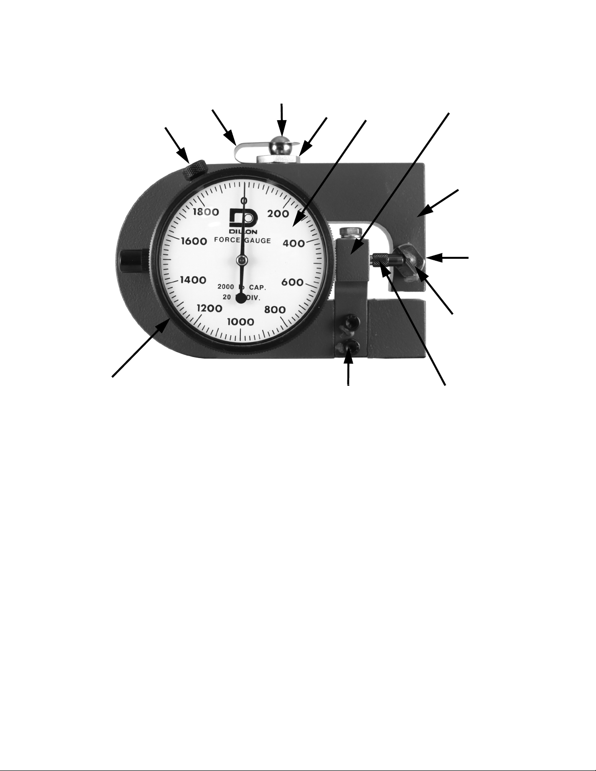
Figure 2.1 shows you the parts of the force gauge. If you have questions about your
force gauge, contact your Dillon service provider and refer to this illustration. A photo
or rough sketch of your particular setup will be helpful.
1 “U” shaped deflection beam
2 Dial indicator
3 Bezel (For zero adjustment purposes)
4 Pressure button
5Anvil
6 Dial indicator gauge movement plunger
7 Anvil set screw
8 Dial indicator mounting bracket
9 Mounting bracket screws
10 Bezel locking screw
11 Loading ball
12 Spring retainer clip
Model X Mechanical Force Gauge User Instructions 9
Page 10
Introduction
1
7
5
6
9
3
10
12
11
4
2
8
*An optional Maximum Pointer is available but not shown
Figure 2.1 Force gauge parts
10 Model X Mechanical Force Gauge User Instructions
Page 11

2.3 Klaxon alarm option
Test Button:
Press to test horn function
Front View
Rear View
Force Gauge with
optional klaxon alarm
Alarm switch
adjustment screw
Only the 5,000kg Force Gauge with Klaxon alarm is CE approved. All other
models are not CE approved.
The force gauge can be attached to an optional klaxon alarm. See Figure 2.2.
2.3 Klaxon alarm option
Model X Mechanical Force Gauge User Instructions 11
The klaxon alarm is rated at 80db(A) @ 0.6 meters (2 feet).
The klaxon alarm is set off when the adjustment screw shown in Figure 2.2 contacts
the switch as the force gauge is compressed. There can be up to four switches
installed. This allows you to control up to four different operations as the gauge is
compressed. See your Dillon representative for information on these options.
Figure 2.2 Force gauge with optional klaxon alarm
Page 12
Introduction
2.4 Operational data
WARNING: Never pick up the force gauge by the dial indicator. This will cause
loss of calibration accuracy, loss of operation or non-warranty damage.
Your Dillon Force Gauge is ready to go to work for you without any special assembly.
Upon removing it from the storage case, it is only necessary to check the zero setting.
1. Place the unit on a flat table with the pressure button, #4, at the top.
2. The dial bezel, #3, is locked lightly by a knurled thumb screw, #10. Loosen the
knurled screw and turn the bezel in either direction, depending upon which
way zero may be off. Revolving the bezel causes the dial to follow.
3. With zero positioned directly under the pointer tip, tighten the locking screw
(see CAUTION below) and the instrument is ready to use.
CAUTION: When adjusting bezel locking screw, #10, only tighten as much as is
necessary to hold bezel in proper position. DO NOT OVERTIGHTEN, as this will
distort the thin housing of the dial indicator gauge and affect the smooth action
of the movement and produce false readings!
Because of the sensitivity of the Dillon Gauge, zero should always be set with the unit
resting on the lower or thicker portion of the deflection beam as illustrated. This is the
same position it occupies during calibration. Ordinarily, zero will be retained indefinitely.
However, under repeated stress or through accidental banging around, it may go off
slightly. Thus, it is a good plan to check zero occasionally.
CAUTION: The small anvil, #6, against which the dial indicator plunger rides,
should never be altered except by factory technicians. This anvil has nothing to
do with zero setting. By careful adjustment, it has been positioned in such a
way that, for full load application within the range of the instrument, the pointer
will revolve 360°. TAMPERING WITH THE SETTING OF THIS ANVIL
AUTOMATICALLY VOIDS THE ACCURACY GUARANTEE. If the anvil should be
accidently thrown out of position by dropping or striking against another
object, the entire gauge should be returned to the factory for resetting and
calibration check.
2.5 Helpful pointers
l Occasionally test the tightness of the hardened dial indicator plunger, #6.
This part is screwed into a finely threaded seat and may sometimes work
loose. This would cause the gauge to read high and might be mistaken for
an off zero condition. Be sure not to force the plunger tip too tightly when
screwing it down since, as explained, the threads are fairly delicate and
might break off.
12 Model X Mechanical Force Gauge User Instructions
Page 13

2.5 Helpful pointers
l Note that threaded mounting holes have been provided in opposite faces of
the “U” shaped deflection beam, #1. In the upper mounting hole, a
spherically recessed pressure button, #4, is screwed. This button is
hardened and plated. It receives the loading ball, #11. Force should be
applied directly against this ball. In operation, the deflection beam bends
inward slightly, and the ball revolves, tending to keep the line of force
vertical. A drop of light oil on the ball assists this action.
l Never fasten the “U” shaped deflection beam in such a way that the free
movement of the upper portion will be restricted. The lower or thicker “leg”,
however, may be tightened as securely as desired, using a stud or bolt
through the threaded mounting hole.
l Since the deflection beam is hardened, it is not possible nor would it be
recommended, to drill and tap it once it is in the field. If special mounting
holes are desired, these can be provided during early stages of
manufacture, but must be specified at that time.
l If a particular test calls for load application through a pulley, roller or chuck,
etc., due care should be taken to see that the load is applied in a true vertical
line through the center of the top mounting hole #4. Off-center loading would
introduce leverage, thereby increasing or decreasing readings from their
true value. Universal joints or hinged fittings should be carefully machined to
obviate side slop or play. If in doubt about the best method of applying load
for specific arrangement, don’t hesitate to consult our Engineering
Department. Remember, a rough pencil sketch or snapshot will aid
tremendously in understanding your problem. Never oil the dial indicator at
any point. It is unnecessary. If oil or other fluids should get on the unit, wipe
off gently, but well. Foreign matter lodging on the plunger, #6 will retard its
free action, resulting in inaccurate readings.
l If accidental overload is anticipated, a solid steel rod about 3/4 inch in
diameter can be inserted at the center point of the Gauge between the “U”
shaped bar. Length of this rod should be figured so that the upper, flexible
half of beam will bottom against it, once the full capacity of the instrument
has been reached. Further load will then pass through this solid path without
harm to the Force Gauge. Note the method of mounting the dial indicator to
the supporting bracket on the reverse side of the case. Allen screws are
used. Be sure to check these screws at intervals, making sure that they are
always tight. Vibration may in time loosen them slightly, and it is best to take
this precaution.
Model X Mechanical Force Gauge User Instructions 13
Page 14

Introduction
2.6 Tensile Model
Generally speaking, the same requirements and suggestions applying to the
compression model force gauge also apply to the tensile unit, shown in Figure 2.3. The
main exception, of course, is that on the tensile model, load is applied through the use
of special end rod bearings.
Figure 2.3 Tensile model with adapters and shackles
These bearings are available for all tensile models as standard equipment. They are a
perfect fit and without any side play. Bearing pins can be machined from drill rod to suit
your particular test plan. Remember that if you require a special adapter of some kind
in place of these bearings, be sure that such adapters are self-aligning so that applied
force is always able to assume a vertical line.
CAUTION: Because there is the possibility that in service the ball-socket
connectors can become unscrewed from the beam, the operator should check
these parts at intervals to make sure that some of the threaded shank is
ALWAYS showing on the inside of the “U” shaped beam. If it is not showing, no
further loads should be applied until the connector is screwed down to its
normal position.
14 Model X Mechanical Force Gauge User Instructions
Page 15

Do not attempt to weld, cotter pin, or otherwise make tensile connectors a solid part of
the bar since every requirement is different as to the length of the shank that has to be
used.
Dillon will not be liable for any incident that might result from accidental or
intentional screw-out or break-away of the ball-socket connectors. For your own
protection, keep these parts properly seated at all time.
Tare settings cannot be made on the Force Gauge without a slightly resultant loss in
accuracy. This is due to the fact that the dial layout is not 100% linear. Each unit is
individually machined and thus must be individually calibrated. While this makes for
split-hair accuracy, division marks are not equidistant and hence do not lend
themselves to tare adjustment. Instead, any tare weight encountered in a typical test
should simply be deducted.
2.7 Push-Pull model
There is one more type of force gauge, a push-pull model, shown in Figure 2.4.
2.7 Push-Pull model
Figure 2.4 Push-pull model force gauge
This model can be used for both tension and compression situations. As you can see
the dial can go in two directions.
2.8 Maintenance and handling
The Dillon force gauge is a precision instrument and will provide many years of
dependable service if given reasonable care and suitable protection. Many firms make
it a regular practice to return force gauges to their distributors at 6 to 8 month intervals
(depending upon how much they are used) to have accuracy recertified. We
recommend this at least once a year. Consult with your Dillon distributor concerning
any questions you may have about recalibration intervals. Your area may require
periodic proof testing. Consult your local regulations.
Transport and store the force gauge in the supplied storage case when not in use.
Model X Mechanical Force Gauge User Instructions 15
Page 16

Introduction
16 Model X Mechanical Force Gauge User Instructions
Page 17

Page 18

AUTHORIZED DISTRIBUTORS
Ask the experts. Dillon distributors offer complete
service capabilities from application assistance to
sales and product support. Their experienced
representatives are the most knowledgeable
experts that you will find in the force measurement
industry. We recommend that you consult these
capable specialists for all of your measuring needs.
Overload Protection and
Overhead Weighing Equipment
1000 Armstrong Drive
Fairmont, Minnesota U.S.A. 56031
Toll-Free: (800) 368-2031
Phone: (507) 238-4461
Fax: (507) 238-8258
Foundry Lane, Smethwick
West Midlands B66 2LP
Tel: +44 (0) 845 246 6717
Fax: +44 (0) 845 246 6718
www.dillon-force.com
Dillon is a brand of Avery Weigh-Tronix
 Loading...