

Page 1
SL 900
Instruction Manual
Version 2.9
illon
recision
Products, Inc.
Manufacturers of
The World’s Finest
Loading Equipment
Page 2

Dillon Precision Products, Inc.
8009 E. Dillon’s Way
Scottsdale, AZ 85260
(480) 948-8009
FAX (480) 998-2786
Web Site: www.dillonprecision.com
E-mail: dillon@dillonprecision.com
Technical Support & Customer Service
(800) 223-4570
On the cover…
The SL 900 is pictured with optional accessories:
Low Powder Sensor #16306
Aluminum Roller Handle #17950
Other accessories available for the SL 900 include:
20 gauge conversion #22138
28 gauge conversion #22139
20/28 casefeed plate #97045
Machine Cover #13329
The Blue Press, Dillon’s monthly catalog, has a complete listing
of accessories available for all machines.
Part #17153 Spot Manuals SL 900 Manual Folder SL 900 Manual.V2.9 10/01 WJC
Page 3

TABLE OF CONTENTS
Parts List, Schematics and Diagrams 5 - 17
SL 900 Machine Mounting Assembly 6
Upper Machine Assembly 7
Shot Container Assembly 8
Casefeeder Assembly & Parts List 9
Casefeeder Bowl Mount & Casefeed Assembly to Frame 10
Lower Machine Assembly 11
Toolhead Assembly 12
Platform Assembly 13
Primerfeed Assembly & Installation 14
Automatic Powder Measure Assembly 15
Shot Dispenser Assembly 16
Wad Swing Arm Assembly 17
Finished Shotshell Dimensions 17
General Machine Information 18 - 19
Step-by-Step Preliminary Assembly 19 - 23
Factory Settings 24 - 25
Filling the Machine with Components – What’s First? 26 - 29
Let’s Begin Making a Few Rounds 29 - 31
Changes and Adjustments 31 - 37
Adjusting the Collet Sizer 31
Powder Die/Funnel Adjustments 32
Adjusting the Automatic Powder System, Powder Charge Weight 32
Adjusting the Wad and Shot Station 32 - 33
Adjusting the Starter Crimp Die 33
Removing the Shot From the Machine 33 - 34
Removing the Toolhead 34 - 35
Shellplate Removal 35 - 36
Switching to Another Powder 36
The Primer System 37
Gauge Conversion - 28 ga. 38 - 42
Gauge Conversion - 20 ga. 43 - 47
Troubleshooting Section 48 - 49
Primer System 48
Casefeeder 48 - 49
General 49
Lube Points 50
Suggested Settings 51
Page 4

5
SL 900 Parts List
Part # Description
10716 Primer Spring Cap
12577 1/2-20 Jam Nut
13311 Spring Pin
13418 Shellplate Bolt
13485 Mainshaft
13613 Clamp
13667 Index Pawl
13677 Ring Indexer
13700 Link Arm Shoulder Pin
13701 3/32x3/8 Dowel Pin
13738 10 Stainless Washers
13742 1/2 E-Clip
13773 8-32 Nut
13789 1/4-28 Set Screw
13791 Indexer Return Spring
13793 Collar Roller
13799 Blue Wing Nut
13801 Tinnerman Nut
13830 Mainshaft Pivot Pin
13837 1/4 E-Clip
13840 Hitch Pin Clip
13841 Nylock Nuts
13848 Bellcrank Bushing
13856 1/4 Washer SAE
13858 Rod Compression Spring
13871 Bellcrank Cube
13891 3/8 Index Ball
13895 10-24x3/8 BHCS
13896 1/4-20 x 3/8 BHCS
13911 1/4-20 x 2 3/4 Bolts
13923 1/4-28 Brass Tip Set Screw
13937 Slide Return Spring
13938 Pawl Spring
13943 1/4-28 Adjustment Bolt
13958 1/4 Washer
13966 1/4-28 x 3/4 SHCS
13988 1/4-20 Nuts
13989 10-24 x 5/8 SHCS
13996 10-32 Set Screw
14008 Toolhead Pins
14013 8-32x3/8 SHCS
14023 8-32 x 3/4 BHCS
14026 8-32 x 1/2 BHCS
14037 10-24 x 3/4 SHCS
14041 1/4 Wave Washer
14118 Index Ball Spring
14574 Case Insert Slide Spring Cap
14689 8-32 x 1/4 BHCS
14808 Collar Roller Bushing
14922 Link Arms
16065 650 Machine Mounts
16209 Spent Primer Cup Bracket
16221 1/4 Fender Washer
16222 1/4-20 x 11/2 Hex Bolts
16340 10-32 Nylock Nut
16667 Toolhead
16668 Toolhead Die Lockplate
16670 SL Crank
16671 Indexing Block
16672 Shotshell Chute
Part # Description
16675 Shellplate, 12 ga.
16676 Ejector Wire
16677 Wad Swing Arm
16678 Wad Guide Sleeve
16679 Sleeve Compression Spring
16680 1/16 x 1/2 Roll Pin
16681 Wad Guide
16682 Swing Arm Torsion Spring
16683 Case Insert Slide
16684 Slide Block
16691 Primer Transfer Arm
16692 Arm Pivot Pin
16693 Transfer Arm Spring
16694 Station Two Locator
16695 Locator Pivot Screw
16696 Locator Torsion Spring
16697 Case Insert Ramp
16698 SL Platform
16699 Spent Primer Cup
16700 Primer Seater Pin
16701 Bushing
16702 Primer Seater Spring
16705 SL Casefeed Tube
16707 Phish Compression Spring
16708 Casefeed Phish
16709 Camming Pin
16710 Clear Primer Tray Cover
16711 Primer Feedplate
16713 SL Primer Slide Upper
16714 Slide/Bellcrank Spring
16717 Primer Feed Cam
16721 Tray Mounting Bracket
16723 Primer Feed Body
16724 Shot Hopper
16725 Shot Dispenser Body
16726 Shot Drop Tube, 12 ga.
16727 Shot Dispenser Bellcrank
16731 Spring (Bellcrank Assembly)
16732 Pivot Pin
16733 Shot Bar Return Rod
16734 Rod Bushing
16735 Shot Body Collar
16736 Body Collar Adjustment Screw
16737 Collar Guide/Clamp
16738 Shot Bar
16739 Shot Bar Insert
16740 3/8-16 Half Dog Set Screw
16741 Depriming Pin
16742 SL Sizer Collet Sleeve
16743 Collet Sizer Die, 12 Ga.
16744 SL Powder Die
16746 Expander Powder Funnel
16747 Starter Crimp Die
16748 Dillon Starter Crimp Insert-1
16750 Final Taper Crimp Die, 12 Ga.
16751 Final Seat Plug, Rem. 12 Ga.
16752 5/8-18 Jam Nut
16753 Locator Buttons
16904 1 1/2-10/32 SHCS
17123 SL 900 Casefeed Post
Part # Description
17124 Shot Post
17125 Dillon Bin
17126 Locator Button Spring
17130 Casefeed Sleeve, 12 Ga.
17131 Casefeed Body
17132 Primer Drop Tube
17134 Primer Bellcrank
17138 Clear Hopper Lid
17139 Shot Dispenser Fitting
17140 Pin (Bellcrank Assembly)
17141 1/4 Hardened Washer
17142 Dispenser Top
17143 Dispenser Top Clear Lens
17146 Rubber Insert
17147 Powder Die E-Clip
17148 1 1/4 Die Lock Ring
17149 1.0 Die Lock Ring
17153 Manual
17182 SL Frame Machined
17202 Shot Fitting E-Clip
17350 Powder Bar Return Rod
17351 Die Lock Bolt
17352 Spring Button
17353 Phish Spring Socket
17354 Gate 3
17472 #8 Washer .032 Thick
17474 10-32 x 5/8 Tray Cover Screw
17476 Shot Drain
17477 Collet Sizer Spring
17479 Clear Industrial Vinyl Tubing
17509 Box
17573 Shot Drain Ext. Spring
17601 Washer .100 Thick
17603 Black Knob
17604 Clevis Pin
17637 1/4-20 x 4 1/2 Hex Head Screw
17639 .175 dia. x 1/4-20 Post
17812 Primer Seater Assembly
17836 Final Seat Plug, A-A 12 Ga.
17837 Tyton Clamp
17838 P/M Lock Link
17839 P/M Slotted Bellcrank
17843 SL 900 Foam Insert Set
17899 Stem Screw
17909 Eight Star Crimp
20782 Dillon Powder Measure
22134 Shot Dispenser Assy - 12 ga.
22183 Roller Handle Assembly
97037 12 Ga. Casefeeder – 110v
97120 Red Flag
N/A Lock Link
N/A Lock Link Torsion Spring
N/A Pivot Pin
N/A Return Spring Pin
N/A Shot Bellcrank Rivet
N/A SL Bellcrank Stud
N/A Spare Parts Bag
Page 5
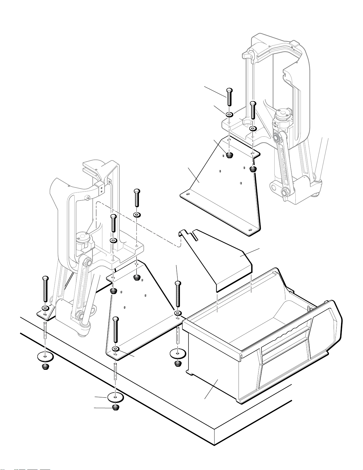
6
SL 900 Mounting Assembly
16065 (2)
16672
17125
16222 (4)
13856 (4)
13988 (4)
13911 (4)
13856 (4)
16221 (4)
13988(4)
Page 6
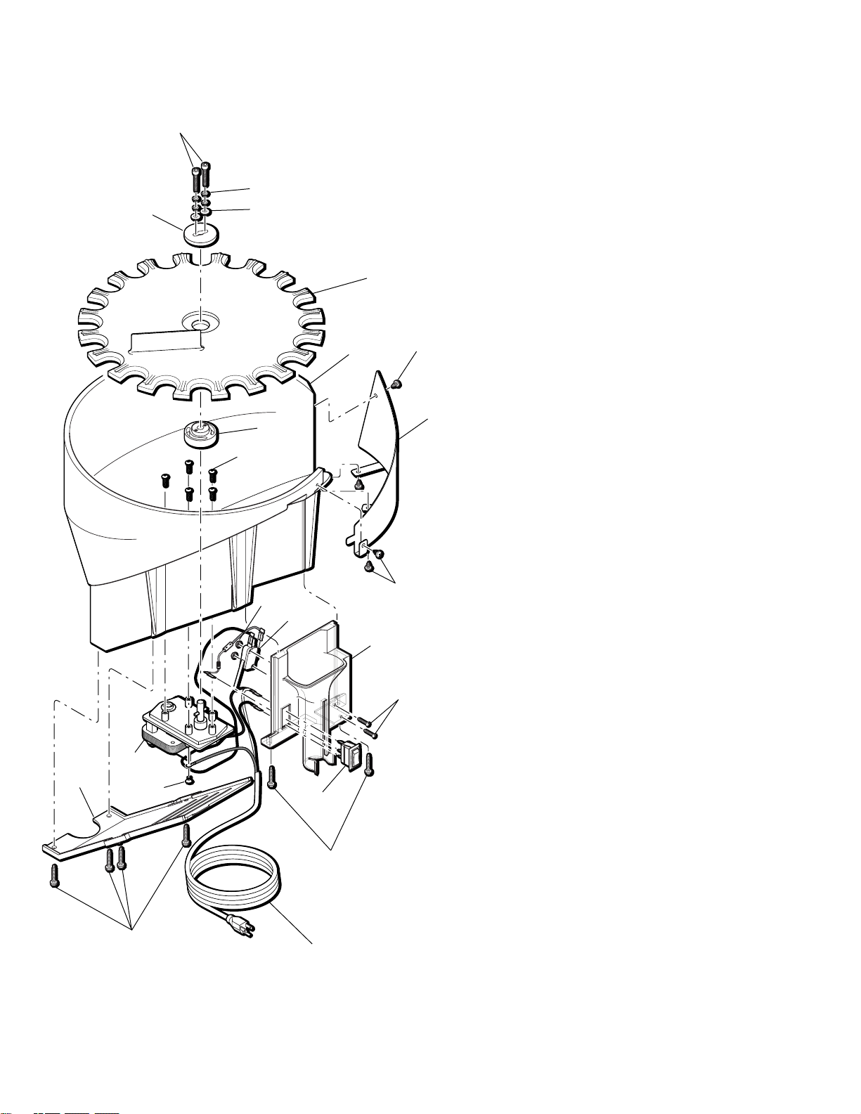
7
Upper Machine Assembly
16676
17123
13418
16675
13966
13667
13791
13938
13677
16699
13856
17637
13989
13989
17637
13856
13613
13988
13613
13613
13988
17124
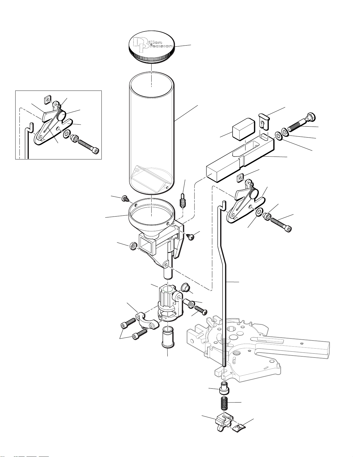
Page 7
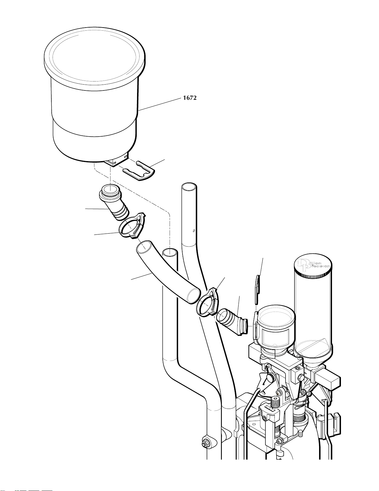
8
Shot Container Assembly
16724
17202
17139
17478
17479
17202
17139
17478
Page 8
9
Casefeeder Assembly Casefeeder Assembly
Parts List
Part # Description
13400 Casefeed Bowl
13473 Casefeed Motor - 4 RPM
13539 Casefeed Cord Set
13540 Casefeed Motor Cover
13632 Casefeed Upper Disc Clutch
13685 1/4-20x5/8 BHCS
13732 10-32x1.00 SHCS
13736 Clutch
13738 SS Washers
13779 Micro Switch
13813 Lockwashers
13833 1/4 Terminal Connector
13903 1/4-20 Heli Coil
13912 8-32 Flat Head Screw
13954 4-40 Screws
14025 1/8x3/4 Roll Pin
14026 Bowl/Motor Screws
14038 40-40 Nuts
14137 8x1 Cover Screw Zn.
16314 Butt. Connector
16334 Lighted Rocker Switch
16336 Red 1/4 female Insulated Connector
16337 Blue 1/4 female Insulated Connector
16704 Shotshell Funnel
17133 Shotshell Disc
17585 Zener Diode 1N5361B
17586 8x1 1/4 Funnel Screw
17587 8x1/4 PHL. PN. Screws
17808 Casefeed Bowl Insert
97037 12 ga. Casefeed Assembly – 110v
13813
13632
17133
13400
13736
17587
(3)
16704
13779
14038
13954
17586
13539
13540
13912
13473
14137
16334
17507
17587
14026 (5)
13732 (4)
13738 (2)
Page 9
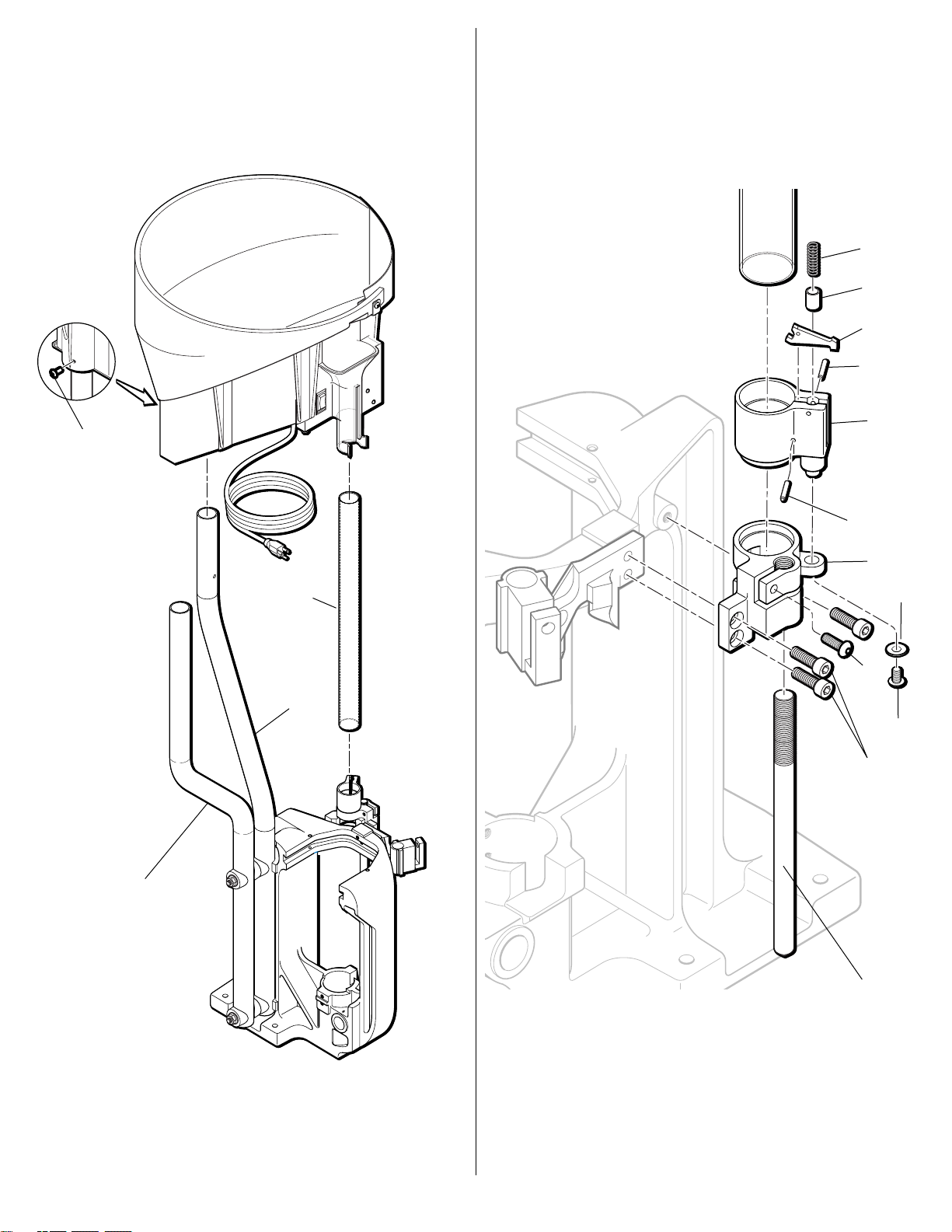
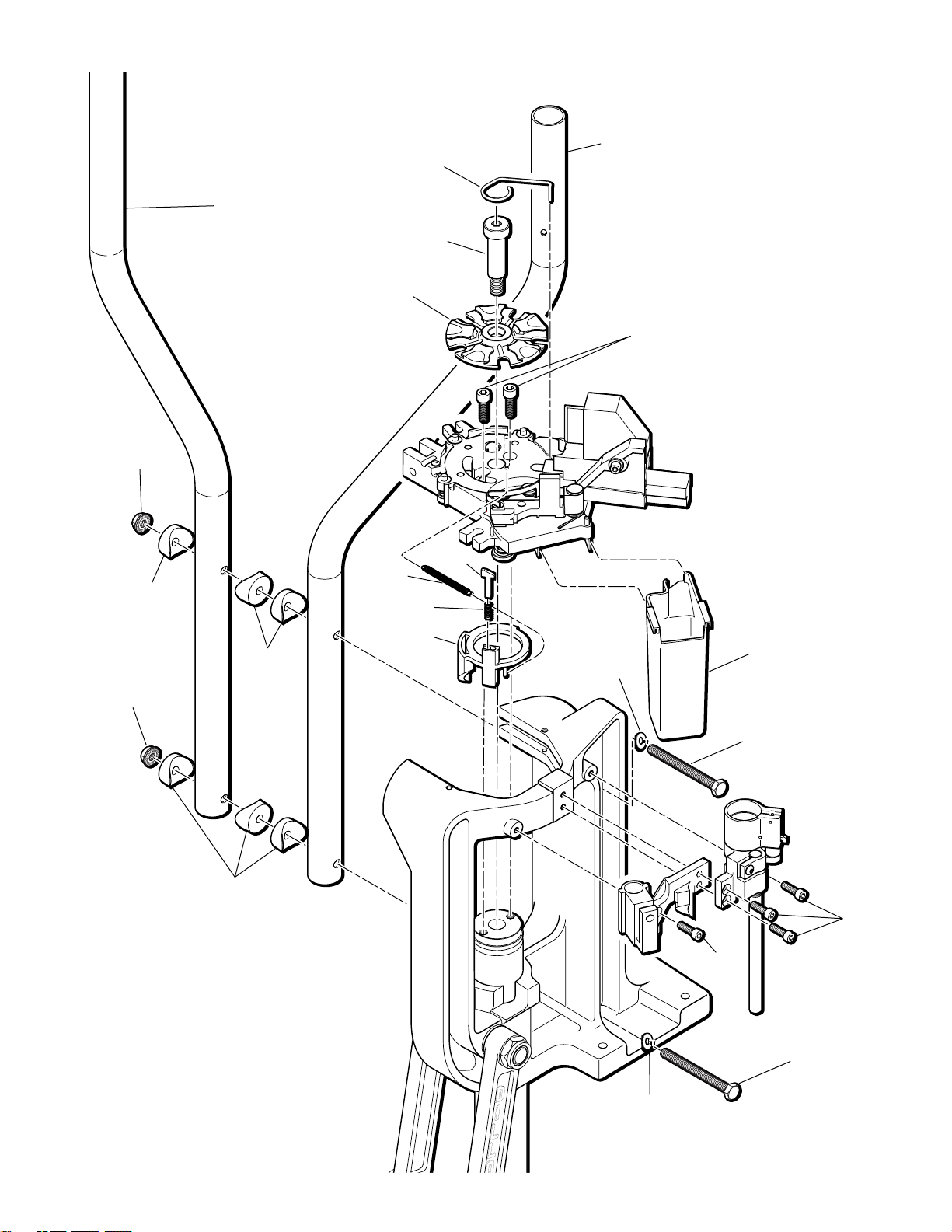
10
Casefeeder Bowl Mount Casefeed Assembly
to Frame
13685
17124
17123
16705
16707
17353
16708
16680
17130
16680
17131
17472
14689
16709
13989 (3)
14026
Page 10
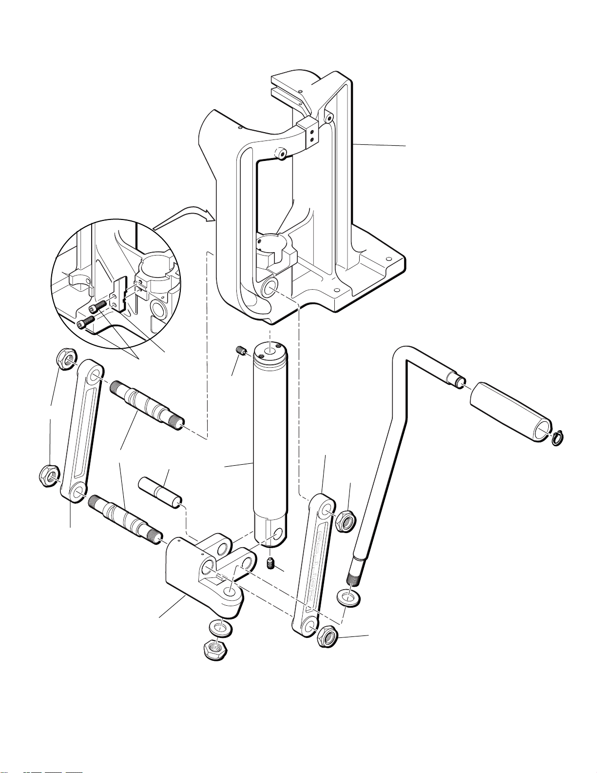
11
Lower Machine Assembly
17182
22183
Handle
Assembly
14922
13841
13841
13789
13485
17637
13830
13700
16670
13841
14922
16671
13989
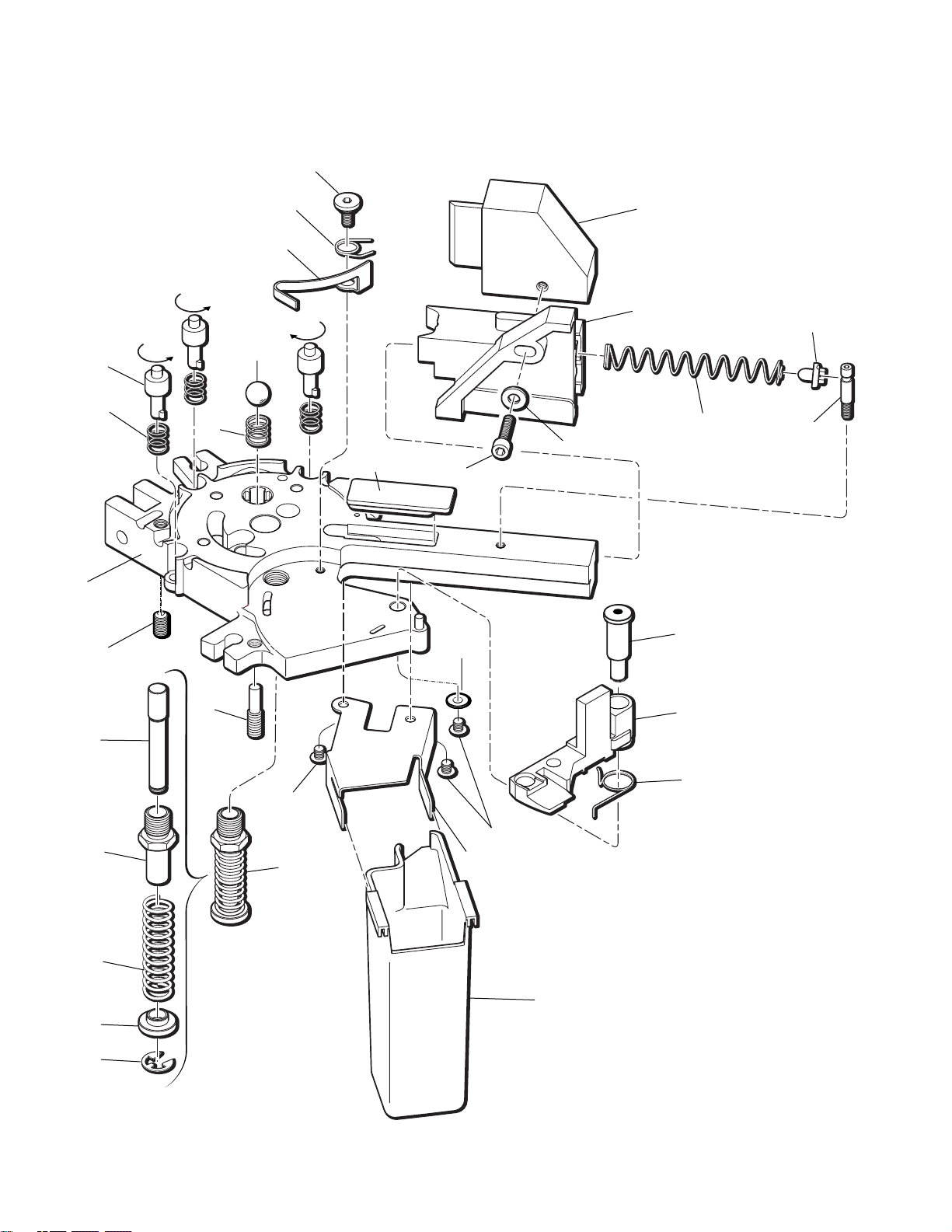
Page 11
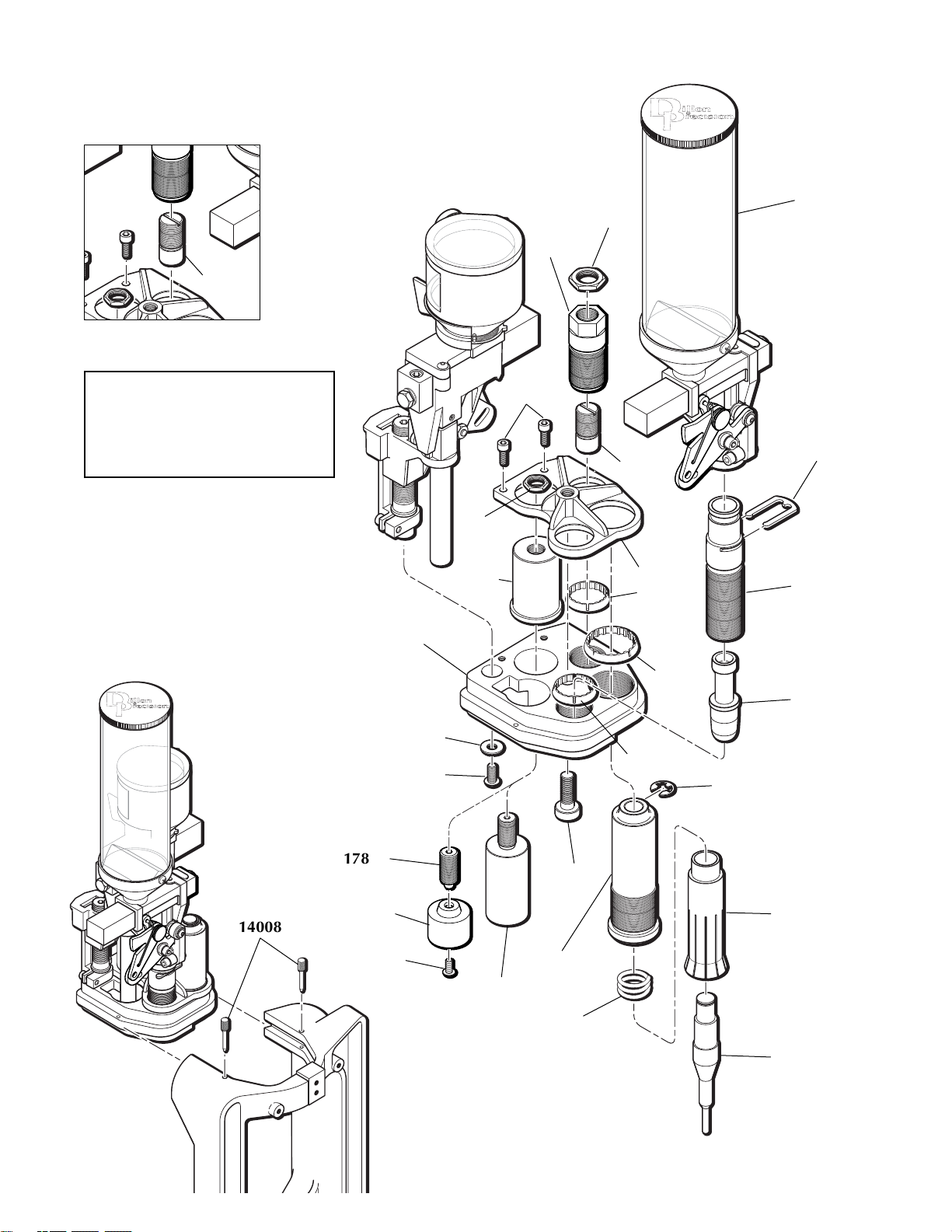
12
Toolhead Assembly
16741
16743
16742
17351
16748
13896
17141
16667
16747
12577
13989
17836
A-A
16668
17149
17148
17149
13742
16750
16752
20782
17147
16744
16746
17477
16751
Remington
14008
17899
17909
13895
Seat Plug Guide
16751 (black) Remington only
17836 (silver) A-A and Federal
Page 12
13
Platform Assembly
16684
16683
13937
13738
14037
16697
17944
13789
16700
16701
16702
17812
assembly
10716
13837
17639
14574
13311
16695
16696
16694
16753 (3)
17126 (3)
13891
14118
16699
16209
14689
14689
16692
16691
16693
17472
Page 13
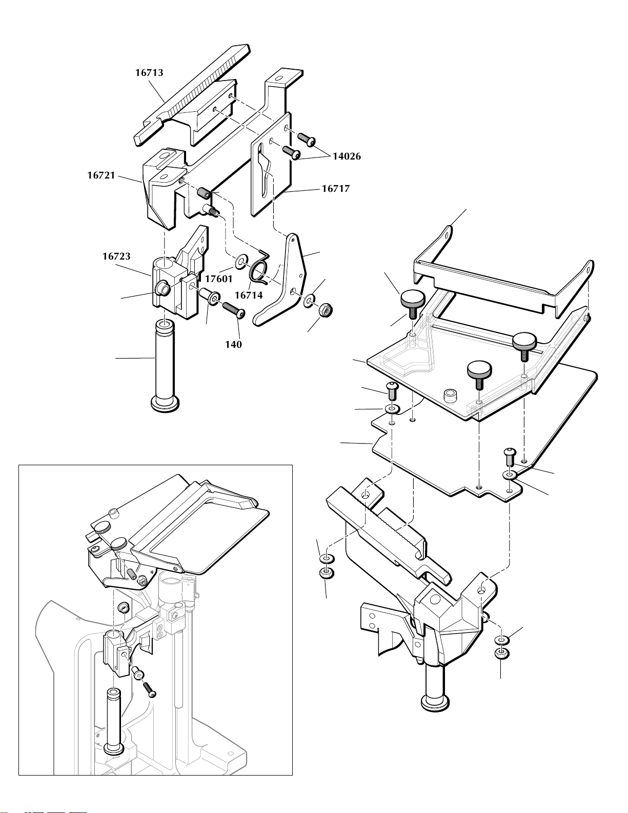
14
Primer Feed System Assembly & Installation
;
;
;
;
;
;
14026
16717
16713
16721
16723
17601
16714
14023
17134
17354
13856
17603 (3)
17474 (3)
16340
14026
16710
17472
17472
17472
13773
13773
16711
14808
13923
13793
17132
14026
17472
Page 14
15
Automatic Powder Measure Assembly
13882
Part # Description
13652 Powder Bar Part, Large
13691 Powder Measure Tube Only
13793 Roller
13799 Blue Wing Nut
13801 Tinnerman Nut
13845 Collar Sleeve
13848 Bellcrank Bushing
13853 Powder Bar Insert, Large
13858 Rod Compression Spring
13871 Bellcrank Cube
13882 Powder Measure Lid
13893 Powder Bar Post, Large
13921 Powder Measure Plug
13939 Body Collar Clamp
13940 Connector Body Collar
13943 Powder Bar Bolt
13958 Powder Bar Bolt Washer
14023 8-32 x 3/4 BHCS
14037 10-24 x 3/4 SHCS (2)
14041 Bowed Washer
14202 Powder Measure Tube Screws
14808 Collar Roller Bushing
16340 Nylon Lock Nut
16731 Spring
16732 Pivot Pin
16734 Rod Bushing
16904 10-32x1 1/2 SHCS
17140 Pin
17350 Powder Bar Return Rod
17838 P/M Lock Link
17839 P/M Slotted Bellcrank
20063 Powder Bar Assembly, Large
22273 Powder Dispenser Body
22273
13691
13793
14808
13940
13845
16734
13858
13801
13799
13871
13958
13652
14041
13943
13893
13853
17839
14041
17350
16904
13939
14037
14023
16340
14202
14202
13921
13848
16732
17839
17838
17140
16731
Page 15
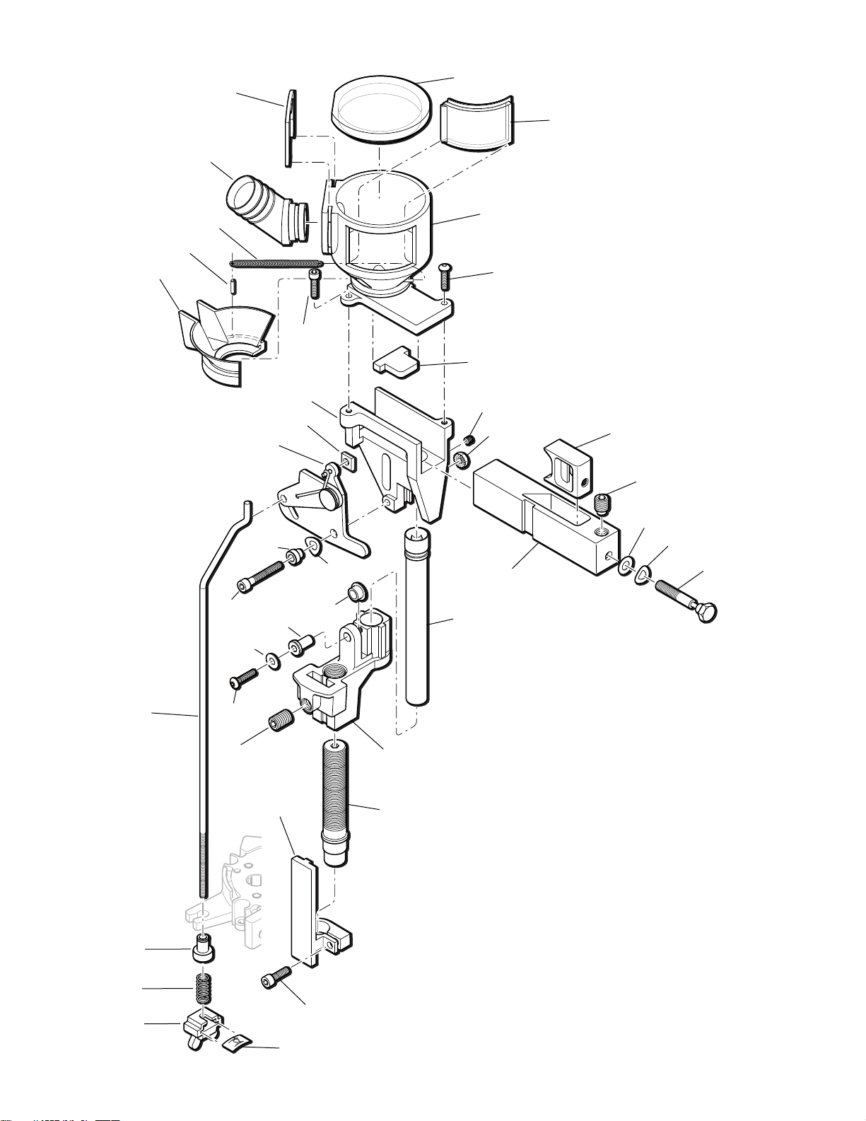
16
Shot Dispenser Assembly - # 22134, 12 gauge shown
17143
17142
14026
17146
13996
13817
16739
16740
13958
16738
16726
16735
16736
16737
16740
14023
13738
14808
16904
13793
14041
13848
16727
13871
16733
13989
13801
13799
13858
16734
14041
13943
16725
17476
14013
13701
17573
17139
17202
17138
Page 16
17
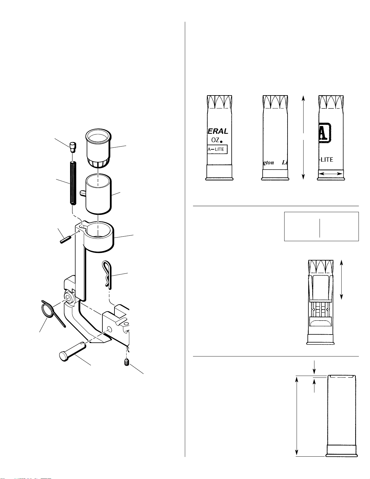
Finished Shotshell Dimensions
Wad Swing Arm Assembly
12 gauge shown
Here are some dimensions of a typical 12ga. shotshell.
Always use a quality dial caliper when measuring your
shotshells. Length may vary dependent upon shotshell
manufacturer. Dimensions shown are for maximum,
uncrimped overall length. If you find it necessary to adjust
the collet size die, try to shoot for a middle of the road
measure of the brass base.
Wad Seated Depth
When developing loads for
shotshells be aware of your “wad
seated depth.” Here’s a reference
guide for the popular wad and
shot weight used presently.
Example, if your loads
currently use a wad for 1 1/8 oz.
of shot and you decide to reduce
your shot weight and switch to
7/8 of an ounce wads, readjust
the shot dispenser tube via the
body collar adjustment screw.
Clockwise rotation raises the
shot dispenser tube and
decreases the depth the wad is
seated into the shotshell.
Counterclockwise rotation
lowers the shot dispenser tube
and the wad will get seated
deeper into the shotshell.
Finished Round Information
Your loaded round length will
vary due to loads used, type of
wads, and brand of shotshells.
We found that a majority of
the Winchester ammo loaded fell
toward 2.30 - 2.325 length.
The Remington and Federal
ammo loaded measured 2.33 -
2.350 overall length.
Always use a reputable
loading manual when reloading
shotshells.
.800-.809 Dia.
typical base
diameter
2.76 -.100
seated depth
.065
2.30 -
2.350
overall
length
16681
16678
NOTE: Periodically
lube this sleeve with
light oil.
16677
16680
13840
16682
17604
17352
16679
Wad & Shot Approx. Depth
7/8 - 1 oz. 1.12 - 1.20
1 1/8 oz. 1.30 - 1.35
1 1/4 oz. 1.45 - 1.50
13789
Page 17

Reloading ammunition and handling powder and
primers is inherently dangerous. Just as in shooting,
accidents do happen. These accidents are
nondiscriminatory; they happen to both the novice and
the experienced reloader.
We have done everything we know how to make
your machine as safe as possible. We cannot, however,
guarantee your complete safety. To minimize your
risk, use common sense when reloading and follow
these basic rules:
Never operate the machine without ear and eye
protection on. Call our customer service department at
(800) 223-4570 for information on the wide variety of
shooting/safety glasses and hearing protection that
Dillon has to offer.
• PAY ATTENTION: Load only when you can give
your complete attention to the loading process.
Don’t watch television or try to carry on a
conversation and load at the same time. Watch the
automatic systems operate and make sure they are
functioning properly. If you are interrupted or must
leave and come back to your loading, always
inspect the hulls at every station to insure that the
proper operations have been completed.
• SMOKING: Do not smoke while reloading or allow
anyone else to smoke in your reloading area. Do not
allow open flames in reloading area.
• SAFETY DEVICES: Do not remove any safety
devices from your machine or modify your machine in
any way.
• LEAD WARNING: Be sure to have proper
ventilation while handling lead components or when
shooting lead bullets. Lead is known to cause birth
defects, other reproductive harm and cancer. Wash
your hands thoroughly after handling anything made
of lead.
• LOADS AND LENGTHS: Avoid maximum loads
and pressures at all times. Use only recommended
loads from manuals and information supplied by
reliable component manufacturers and suppliers. Since
Dillon Precision has no control over the components
which may be used on their equipment, no
responsibility is implied or assumed for results
obtained through the use of any such components.
Refer to a reliable loading manual for overall length
(OAL).
• QUALITY CHECKS: Every 50-100 rounds, perform
periodic quality control checks on the ammunition
being produced. Check the amount of powder being
dropped and primer supply.
• RELOADING AREA: Keep your components safely
stored. Clear your work area of loose powder, primers
and other flammables before loading.
• COMPONENTS: Never have more than one type of
powder in your reloading area at a time. The risk of a
mix-up is too great. Keep powder containers closed.
Be sure to inspect hulls prior to reloading for flaws,
cracks, splits or defects. Throw these hulls away.
Keep components and ammunition out of reach of
children.
• WINCHESTER HULLS: Please be aware that
Winchester has redesigned the AA target hull. This
hull is no longer a one-piece extruded design. Now, it
is a two-piece hull incorporating an inner reinforcing
tube which extends partway up the interior of the hull.
Winchester wads have been redesigned to work
with this new design. Additionally, some aftermarket
wads are now available which are compatible with the
redesigned hulls. Other wads may not be compatible
with the new AA hulls.
We suggest that you visually inspect your hulls,
and load the old and new style hulls separately, using
components appropriate to each style of hull.
• BLACK POWDER: Do not use black powder or black
powder substitutes in any Dillon powder measure.
Loading black powder cartridges requires specialized
loading equipment and techniques. Failure to do so
can result in severe injury or death.
• PRIMERS: Never force primers. If they get stuck in
the operation of the machine, disassemble it and gently
remove the obstruction.
Never attempt to deprime live primers – eventually
one will go off. When it does it will detonate the others
in the spent primer cup. Depriming live primers is the
single most dangerous thing you can do in reloading
and can cause grave injury or death.
• LOADED AMMUNITION: Properly label all of your
loaded ammunition (Date, Type of wad, primer,
powder, shot charge, etc.).
• BE PATIENT: Our loading equipment is
conservatively rated and you should have no trouble
achieving the published rates with a smooth, steady
hand. If something doesn’t seem right, stop, look and
listen. If the problem or the solution isn’t obvious, call
us. The reloading bench is no place to get into a hurry.
• REMEMBER: If your machine does not perform to
your expectations, or if you are having technical
difficulties, give us a call: (800) 223-4570
GENERAL MACHINE INFORMATION
Based on our XL 650 machine frame, the SL 900
comes to you with some great automated features.
Starting from the right rear of the machine, the
SL 900 features an electric casefeeder. This unit
holds approximately 80 empty hulls; enough for
three boxes of shotshells.
Turn the electric casefeeder on and the shotshell
disc (#17133) will rotate until the feed tube has
filled, then the microswitch will shut the unit off.
Every stroke of the roller handle (#22183) transfers
one empty hull from the feed tube to the shellplate
via the case insert slide ramp. Once a hull has been
placed in station one of the machine, moving the
roller handle (#22183) down will resize the brass
base of the hull, expand the mouth of the hull and
remove the old primer. NOTE: Always examine the
hulls for rocks, dirt, mud or other cases that may get
stuck inside. Also look for hulls that may appear
stepped on or flattened. Go ahead and squeeze them
18
M
ANDATORY
S
AFETY
M
EASURES
Page 18

round again so they won’t get stuck in the casefeed
tube (#16705). Returning the roller handle (#22183)
to its full aft position will advance the hull to station
two, where a new primer is inserted into the hull
when you push the roller handle (#22183) aft.
The automatic primer system holds 100 shotshell
primers. Every complete stroke of the roller handle
(#22183) will feed a primer to the hull.
The automatic powder system is also located at
station two. The hopper holds one half pound of
powder and has a fully adjustable powder bar. The
automatic powder system is hull activated. Move
the roller handle (#22183) down. When the hull
contacts the expander/powder funnel (#16746), the
powder measure is pushed up, causing the powder
bar to move and dispense one charge of powder into
the hull. Raise the roller handle (#22183) to its rest
position. The powder bar will recharge and the hull
will advance to station three.
At the third station (left, front of the machine) we
will insert the wad and meter the shot into the shell.
Move the roller handle (#22183) aft as if you are
seating a primer into the hull. You will see the wad
swing arm (#16677) tilt out, ready to accept a new
wad. With every complete stroke of the roller handle
(#22183), insert a new wad into the wad swing arm
(#16677) when it tilts out.
Move the roller handle (#22183) down. The shot
drop tube (#16726) inserts the new wad into the
empty hull and will dispense shot into the hull.
Raise the roller handle (#22183) and push aft to
prime. Hold the handle aft while you insert a wad
into the swing arm.
At station four we start the crimp in the top of
the loaded hull. It is formed and folded closed,
preparing the hull for the final crimp and seating
performed in station five.
The formed, folded top of the hull will now be
crimped and seated closed. This die is fully
adjustable. The crimp and seating depth can be
adjusted to the desired settings.
This die also has a taper crimp feature inside that
will form a tapered end to the hull. Again, move the
roller handle (#22183) down and then back up to its
rest position. The completed shotshell advances out
of the machine, down the shotshell chute (#16672)
and into the Dillon bin (#17125).
STEP BY STEP PRELIMINARY ASSEMBLY
1. Fasten the strong mounts (#16065) to the base
of the machine while it is lying on its side. Fig. 2
19
Fig. 1 - A.) Dillon Bin B.) Shotshell Chute C.) Strong Mounts D.)
Universal Mounting Kit and Hardware needed for Strong Mount
installation E.) Shot Container and Post F.) Shot Dispenser Hardware
G.) Shot Bar Return Rod and Powder Bar Return Rod
H.) SL 900 Toolhead and Frame I.) Spent Primer Cup J.) powder
measure K.) Roller Handle L.) Hardware for Shot Post and Casefeed
Post Assembly M.) Casefeed Bowl and Post N.) Clear Casefeed Tube
A.
B.
C.
D.
E.
F.
G.
H.
I.
J.
K.
L.
M.
N.
Fig. 2
Page 19

20
2. Lift the machine up and fasten the machine
securely to the forward edge of the bench. Fig. 3
3. Install the casefeed post (#17123) and the shot
post (#17124) to the frame of the machine using the
two long 4 1/2" bolts, 6 clamps (#13613), 2 - 1/4"
washers and 1/4-20 nuts. Fig. 4
4. Locate the shot container and place it on its
post. Fig. 5
5. Open the casefeeder box. Place the feeder on
your bench and plug it into a 110v AC outlet (220v
for European casefeeders). Place a handful of empty
hulls into the casefeeder (approximately 10). Turn
the unit on and familiarize yourself with its
operation. Notice how every time an empty hull
exits the casefeeder, it passes a microswitch. Later in
the loading process, you will see that every time the
hull is next to the microswitch the motor will shut
off. Fig. 6
6. Place the casefeeder on its post. Find the
clear feed tube and place the bottom of the tube
into the 12 Ga. casefeed sleeve (#17130). Align the
casefeeder on the post with the clear feed tube and
snap the feed tube into its receiver. Snug the 1/420 screw on the rear of the casefeeder to secure the
position of the casefeeder. Please do not fill the
clear feed tube with empty hulls. This step will be
completed later. Fig. 7
Microswitch
Fig. 3 Fig. 6
Fig. 5
Fig. 7
Fig. 4
Page 20

Be sure to secure the small, but important, screw
located at the rear of the bowl at the base. This little
screw (#13685) secures the entire bowl assembly to
the casefeed post (17123). Fig. 8
7. The powder measure (#20782) is the next item
we’ll be installing on the machine. Familiarize
yourself with its operation – every complete stroke
of the powder bar dispenses one charge of powder.
The dispenser is hull activated.
Using a 7/16” wrench, rotate the bolt located on
the end of the powder bar – counterclockwise will
reduce the powder charge weight, clockwise will
increase the powder charge weight. Fig. 9
Be sure to install the powder measure plug
(#13921) here – see arrow Fig. 9.
8. Remove the blue cap on the powder die
(#16744). Loosen the two Allen screws and place the
powder measure (#20782) on the powder die
(#16744). The clamp must lock into the groove of the
die, then secure the two Allen screws firmly. Fig. 10
9. Locate the parts bag for your machine.
Enclosed is a powder bar return rod (#17350) Fig.
11. The powder bar return rod (#17350) must be
inserted into the bellcrank from its left side. On the
bottom of the rod is a blue wing nut (#13799),
spring and white rod bushing (#16734). Slide this
end into the receiver (see arrow Fig. 11) and snap
21
13685
Fig. 8
Fig. 9
Fig. 10
Fig. 11
#13921
Page 21

the rod bushing (#16734) into the platform. Thread
the blue wing nut (#13799) “up” until there’s some
spring tension against the platform – two to three
turns. Do not fill the powder measure (#20782) at
this time. This will be completed later.
10. Next we move to station three where the wad
is seated and the shot is dispensed. The Dillon shot
dispenser works similar to the powder measure
(#20782). The shot dispenser is activated by the hull
at this station. No hull – no shot. Every complete
stroke of the shot bar dispenses one charge of shot.
To adjust, loosen the bolt set screw (#16740) 1/4 of a
turn. Then use a 7/16” wrench to rotate the bolt
located on the end of the shot bar (#16738) –
counterclockwise will reduce the shot weight and
clockwise will increase the shot weight. Fig. 12
11. To complete the assembly of the shot
dispenser tube, you’ll need the following items
from the parts bag: shot bar return rod (#16733),
clear shot feed tube, two shot dispenser fittings
(#17139), two shot fitting e-clips (#17202) and two
tube clamps. Fig. 13
12. Assemble the shot dispenser fittings to the
clear shot feed tube. Fig. 14 Place the tube clamps
loosely on the tube. Slide one end of the shot
dispenser fitting into the bottom of the shot hopper
(#16724 item A Fig. 13) and lock it in using one of
the shot fitting e-clips. Now, align the complete
assembly and install the other shot dispenser
fitting and e-clip into the dispenser top (#17142)
and tighten the clamps. Fig. 15
22
Fig. 12
Fig. 14
Fig. 15
Fig. 13
A
Page 22

13. When installing the shot bar return rod
(#16733), use your left hand to move the lock link
down over the slot in the shot dispenser bellcrank.
Fig. 16 Now, insert the hook end of the shot bar
return rod (#16733) through both parts. On the
bottom of the rod is a blue wing nut (#13799), spring
and white rod bushing (#16734). Slide this end into
the receiver and snap the rod bushing in the
platform. Thread the blue wing nut (#13799) “up”
until there is some spring tension against the
platform – two to three turns. Do not fill the shot
dispenser at this time.
14. Place the spent primer cup (#16699) on its
spent primer cup bracket (#16209), it’s located on
the lower right hand side of the machine’s platform
– slide the cup onto the bracket rails. Fig. 17
15. Position the Dillon bin (#17125) on the
machine’s right side, then place the shotshell chute
(#16672) between the machine and the Dillon bin
(#17125). Fig. 18
16. Finally, install the roller handle (#22183).
Fig. 19
23
Fig. 17
Fig. 19
Fig. 18
Fig. 16
Page 23

The SL 900 shotshell machine has been
assembled and tested using Winchester AA hulls. A
sample is included with the machine.
Station One – The collet sizer is adjusted for
resizing the brass base. Fig. 20
Station Two – Inside the powder die (#16744)
you’ll find the powder funnel Fig 21. This part
uniforms the top of the shotshell hull and dispenses
one charge of powder into the hull. The powder bar
will need to be adjusted to the desired powder
weight. Its important to use a quality powder scale
to do this. Fig 21A
The powder die has been adjusted to a height so
that the powder measure bellcrank can make full
strokes when activated. Fig 21B. Turning the
powder die (#16744) counterclockwise will raise the
powder system, reducing the amount of stroke the
bellcrank has. Fig 21C.
Station Three – Two operations occur here
involving wad and shot insertion.
In the wad swing arm (#16677) we’ve installed a
caliber specific wad guide (#16681). Fig. 22
24
Fig. 21
Fig. 20
Fig. 21B
Fig. 21C
Complete Stroke
Incomplete Stroke
Fig. 22
FACTORY
S
ETTINGS
Fig. 21A
Page 24

The shot bar has a preliminary setting for 1 1/8
oz shot weight. The shot bar will need to be adjusted
to your desired weight. Fig 23A
The body collar adjustment screw (#16736) has
been adjusted to seat the 1 1/8 oz (WAA-12) plastic
wad into the hull. The shot dispenser bellcrank
makes a complete stroke and dispenses one charge
of shot wile the wad is being seated into the hull.
Fig 23B
Turning the body collar adjustment screw
(#16736) clockwise (too high) will raise the shot
dispenser, reducing the amount the wad is seated
into the hull and may result in an incomplete stroke
of the bellcrank. Fig 23C
Station Four – The starter crimp die (#16747)
forms and folds the loaded shotshell hull. This die is
set for Winchester AA hulls so we achieve 60%
closure of the top. Fig. 24
Station Five – Here we’ll finish crimp and seat.
A final seat plug (#16751) presses the hull back
down and below the top by approximately 1/16 of
an inch. The taper crimp feature within the die
radiuses and blends the end of the hull and locks
the crimp on the hull. It too is adjusted for
Winchester AA hulls. Fig. 25
25
Fig. 25
Fig. 24
Fig. 23A
Fig. 23B
Fig. 23C
Complete Stroke
Incomplete Stroke
16739
16740
Remember: Loosen the
bolt set screw before
making any adjustments.
13958
16738
14041
13943
Page 25

Before you charge ahead and begin tossing
components into your new SL 900 shotshell
machine, there is a routine we’d like you to follow.
1. Fill the powder hopper with the powder of
your choice. Fig. 26 2. You will need a once-fired
shotshell with a spent primer. Fig. 27 3. You will need
a powder scale to weigh the powder charges. Fig. 28
4. Place the hull in station two where the powder
measure (#20782) is located. Gently move the station
two locator (#16694) away from the shellplate and
insert the hull. Fig. 29
5. Move the roller handle (#22183) down and
then back to its rest position. Remove the hull from
the shellplate by pressing down on the locator
button (#16753) and pour the powder back into the
clear powder hopper. Fig. 30
6. Repeat steps 4 and 5 a minimum of four times
so you are receiving a uniform powder charge.
7. Weigh the fifth powder charge. Using a 7/16”
wrench, rotate the bolt located on the end of the
powder bar. Counterclockwise will reduce the
powder charge weight. Clockwise will increase the
powder charge weight. Adjust as needed.
8. Again, repeat steps 4 and 5 until you’re happy
with the powder charge.
Now that you have determined the powder
charge, let’s go on to station three for wad and shot
insertion. Let’s use the same hull, with powder, in
station three.
1. Get a supply of wads.
2. Move the roller handle (#22183) to its full aft
stop position, away from you. Doing so will cause
the wad swing arm (#16677) to pivot out so you can
insert the wad. Fig. 31 Let the roller handle (#22183)
return to its rest position.
3. Remove the clear hopper lid (#17138) and add
a small amount of shot to the shot dispenser. Fig. 32
26
D-Terminator
Electronic Scale
#13681
(pictured)
Eliminator
Beam Scale
#13480
Fig. 29
Fig. 31
Fig. 32
Fig. 26 Fig. 27 Fig. 28
Fig. 30
FILLING THE MACHINE WITH COMPONENTS. WHAT’S FIRST?
Page 26

4. Move the roller handle (#22183) down and
then back up to its rest position. Remove the hull
from the machine by pressing down on the locator
button (#16753) and pour the shot back into the shot
dispenser. Fig. 33
5. Place the hull back into station three and again
move the roller handle (#22183) down and then
back to its rest position. Remove the hull and weigh
the shot charge. Fig. 34
6. Loosen the bolt set screw (#16740) 1/4 of a
turn. Then using a 7/16” wrench, rotate the bolt
located on the end of the shot bar (#16738).
Counterclock- wise turns will reduce the shot charge
weight. Clockwise turns will increase the shot
charge weight. Adjust as needed. NOTE: Its always
easier to make adjustments when the bar is empty
and in the forward drop position.
7. Again, repeat steps 4 and 5 until you’re happy
with the shot charge. Remember to place the clear
hopper lid (#17138) back onto the shot dispenser &
tighten the bolt set screw (#16740).
Now that you have determined the shot charge,
let’s move on to station four and five where the
starter crimp die (#16747) and final seat/crimp
functions are performed. Let’s use the same hull
(with shot).
1. Place the hull (with shot) into station four.
2. Move the roller handle (#22183) down and
then back to its rest position. The formed and folded
hull has just completed station four and has
advanced to station five. Fig. 35
3. Once again, move the roller handle (#22183)
down. As you return to the rest position, you’ll see
the completed round advance and move out of the
machine. The completed round will fall down the
shotshell chute (#16672) and land in the Dillon bin
(#17125). Fig. 36
Review the dummy round you’ve just made.
Let’s go ahead and make one more dummy round.
Please note, when making these dummy rounds, we
start at station two and then go through all the
remaining stations on the machine. This is the
introductory process. Next we’ll be adding empty,
fired hulls and new primers.
27
Fig. 36
Fig. 35
Fig. 34
Fig. 33
Page 27

1. Using a Dillon bin (#17125) or box, gather up
to 80 empty, fired hulls. Fig. 37
2. Always examine the hulls for rocks, dirt, mud
or other cases that may get stuck inside. Also look
for hulls that may appear stepped on or flattened.
Go ahead and squeeze them round again so they
won’t get stuck in the casefeed tube (#16705). Fig. 38
3. Pour the hulls into the casefeeder and turn
the unit on.
4. The casefeeder will run until the casefeed tube
(#16705) has filled, then shuts off automatically
when a hull trips the microswitch. Fig. 39 Insure
that the casefeed tube is fully seated into its clamp.
5. Get one box of new shotshell primers.
6. Slide the cardboard jacket back, exposing only
half of the first row of primers. Fig. 40
7. Turn the box of primers over.
8. Place the leading edge of the primer tray into
the machine’s primer feedplate (#16711). Fig. 41
9. Slide the cardboard jacket off. Helpful hint – as
you slide the cardboard jacket off, place your lefthand index finger on the primer tray and press
down as you slide the jacket off. Fig. 42
28
Fig. 37
Fig. 38
Fig. 41
Fig. 42
Microswitch
Fig. 40
Fig. 39
Page 28

10. Lift the plastic primer tray straight off the
primers. Do not rotate. Check that no primers have
turned on their side. If so, straighten. Fig. 43
11. Raise the primer gate and the group of
primers will slide down to the primer slide upper
(#16713). Fig. 44
Note that every complete stroke of the roller
handle (#22183) will feed one primer into the
machine while at the same time completing the
other processes within the machine.
LETS BEGIN MAKING A FEW ROUNDS
If you’re like me, you have already figured out
that when you cycle the roller handle (#22183), hulls
feed into the shellplate and primers also feed into
the machine. Let’s begin making a few rounds and
I’ll explain the loading process, using the first hull as
our guide.
1. With all the stations empty, move the roller
handle (#22183) down and then back up to its full
aft position. A hull has been fed into the shellplate.
Fig. 45
2. Push the roller handle (#22183) aft, away from
you. Doing so inserts the hull fully into the
shellplate and the first primer appears at station
two. Remove this primer and set it aside. Fig. 46
3. Move the roller handle (#22183) down. The
first hull is being resized and the old primer has
been removed from the hull.
4. Return the roller handle (#22183) to its rest
position. The first hull advances to station two and
another hull has been fed to the shellplate. Fig. 47
5. Push the roller handle (#22183) aft, away from
you. Doing so seats the new primer into the first hull
at station two, and another hull is fully seated into
the shellplate at station one. To ensure that you have
fully seated the primer into the hull, it is important to
stroke the operating handle to its full aft position.
29
Fig. 47
Fig. 48
Fig. 45
Fig. 46
Fig. 44
Fig. 43
Page 29

With experience, you will acquire the “feel” of the
primer being seated fully. Fig. 48
6. Move the roller handle (#22183) down. The first
hull is getting a charge of powder at station two.
7. Return the roller handle (#22183) to its rest
position. The first hull advances to station three,
another fired hull is fed to the shellplate and the hull
at station two is ready to receive a new primer. Fig. 49
8. Push the roller handle (#22183) to its full aft
stop and hold as (using your left hand) you pick up
a plastic wad and place it into the wad guide
(#16681). This same aft stroke seated the new primer
into the hull at station two and the hull at station
one is fully seated into the shellplate. Release the
roller handle (#22183). Fig. 50
9. Move the roller handle (#22183) down. The
first hull is at station three, where a new plastic wad
is seated. It then receives a charge of shot. Again, the
hulls in station one and station two are being
processed as well. Fig. 51
10. Raise the roller handle (#22183) to its full aft
stop. The first hull advances to station four and the
other hulls advance as well. Fig. 52 If you encounter
resistance, STOP! Do not force the handle. There
may be something blocking the primer transfer arm.
See the troubleshooting section for instructions on
how to proceed.
11. Push the roller handle (#22183) aft to seat the
primer into the hull at station two and place a new
plastic wad in the wad guide (#16681).
Special note: An important step in the loading process
– remember when pushing the roller handle (#22183) aft
to seat the new shotshell primer, you must also place a
new plastic wad into the wad guide (#16681) at the same
time. See Fig. 50
12. Move the roller handle (#22183) down. The
first hull is being formed and folded with the starter
crimp die (#16747) at station four.
13. Return the roller handle (#22183) to its full aft
position. All the hulls advance one station. The first
hull is now in station five. Fig. 53
30
Fig. 52
Fig. 53
Fig. 49
Fig. 50
Fig. 51
Page 30

14. Push the roller handle (#22183) to its full aft
stop, seat the primer into the hull at station two and
place a new plastic wad in the wad guide (#16681).
15. Move the roller handle (#22183) down. The
first hull is at the last process. The final crimp and
seating die finishes closing the top. A final seat plug
(#16751) presses the hull back down and below the
top. Fig. 54
16. Return the roller handle (#22183) to its rest
position. The first hull advances and moves out of
the machine. Fig. 55
17. Again, push the roller handle (#22183) to its
full aft stop, seat the primer into the hull at station
two and place a new wad in the wad guide (#16681).
We’ve now reached the stage in the reloading
process where all the stations in the machine are
filled. From here on out every complete stroke of
the roller handle (#22183) will give you one
completed round.
WHEN OPERATING THE ROLLER HANDLE:
Pay close attention to the hulls, noting the
changes that take place as they go through the
machine. Pace yourself when operating this machine.
Do not crash the roller handle (#22183) down against
its stops. Do not snatch the roller handle (#22183)
upward. It should take two or more seconds to move
the roller handle (#22183) from its rest position,
down, and then back to its rest position.
Changes and Adjustments
Whenever you plan to make some changes or
adjustments to your SL 900 machine, it’s important
to have all the right tools. Fig. 56
1 - Dial Caliper
2 - Scale
3 - One complete set of Allen wrenches
4 - 7/16” box/open end wrench
5 - Loading Manual
6 - Empty plastic container or coffee can
1. Adjusting the 12 Ga. Collet Sizer Die – Two tools
are needed when adjusting the 12 Ga. collet sizer die
(#16743). A 3/16” Allen wrench and a dial caliper.
Loosen the die lock bolt (#17351) located in the
bottom of the toolhead (#16667). Fig. 57
31
Fig. 56
Fig. 57
Fig. 54
Fig. 55
Page 31

Using a fired hull, measure the diameter of the
brass base. Place the hull into the machine’s
shellplate at station one and resize the hull. Remove
the hull from the machine and again measure the
diameter. The brass base should be .804 diameter.
Fig. 58 See page 17 for shotshell dimensions.
To make the brass base smaller, turn the die
clockwise using one-quarter turn increments. Using
another fired hull to test the new setting, resize the
hull in the machine. Again, measure the diameter of
the brass base. When you’re finished, tighten the die
lock bolt (#17351).
2. Powder Die/Funnel Adjustments – When a
powder charge is dropped into a hull, it is very
important that the bell crank also makes a complete
stroke simultaneously. Fig 59 Turning the powder
die (#16744) clockwise lowers the powder system
and increases the stroke of the bellcrank. Be careful
not to go down too far or you may crush a hull.
Turning the powder die (#16744) counterclockwise
will raise the powder system, reducing the amount
of stroke the bellcrank has. Fig. 60
3. Adjusting the Automatic Powder System
Powder Charge Weight – Place a hull at station two
and cycle the handle. Weigh the powder charge from
the hull and write that weight down. Using a 7/16”
wrench, rotate the bolt located on the end of the
powder bar. Fig. 61 Counterclockwise will reduce
the powder charge weight, adjust as needed.
Helpful hint: operate the powder bar a minimum of
four times so you are assured of a uniform powder
charge, then weigh the fifth charge.
4. Adjusting the Wad and Shot Station – Shot charge
weight adjustments: Weigh the shot charge from a
hull and write that weight down. Refer to your
loading manual to decide whether you need to
increase or decrease the shot charge weight. Using a
7/16” wrench, rotate the bolt on the shot bar (#16738)
clockwise to increase the weight or counterclockwise
to reduce the weight. Adjust as needed.
Adjusting the Plastic Wad Depth – A sample
plastic wad was included with your SL 900 machine
when it was built and adjusted at the factory. If you
have selected a wad that uses a lighter or heavier
load of shot, you’ll need to readjust the position of
the shot dispenser. Using a 5/32” Allen wrench,
loosen the two screws on the collar guide/clamp
(#16737). Fig. 62 A 3/16” Allen wrench is used to
rotate the body collar adjustment screw (#16736).
32
Fig. 62
Fig. 61
Fig. 58
Fig. 59
Complete Stroke
Fig. 60
Incomplete Stroke
Page 32

When reloading with light shot load plastic
wads it may be necessary to adjust the shot
dispenser position. Rotate the body collar
adjustment screw (#16736) clockwise to raise the
shot dispenser. Tighten all the collar screws, then
test the changes. Fig. 63
When reloading with heavy shot load plastic
wads it may be necessary to adjust the shot
dispenser position. Rotate the body collar
adjustment screw (#16736) counterclockwise to
lower the shot dispenser. Tighten all the screws, then
test the changes.
5. Adjusting the starter crimp Die – This die has
been adjusted at the factory using Winchester AA
hulls. If you have another brand of hull you’d like to
reload, it may be necessary to readjust this die. Test
run a hull through the machine to decide if any
changes are needed.
What we like to see is a 60% closure of the top,
formed and folded. This is important so that station
five’s final crimp/seat can produce a uniform folded
crimp. Fig. 64
We found that when we reloaded Remington
hulls and wads, we would need to adjust the starter
crimp die (#16747) down. The heavier walled
Remington hulls appear to be somewhat more
resistant to being formed and folded. Turn the
starter crimp die (#16747) down approximately onehalf turn clockwise as needed.
Reloading with Federal hulls and wads requires
a little readjusting as well. Raise the starter crimp
die (#16747) approximately one-half turn counterclockwise. This will help produce a uniform folded
crimp/seat.
Winchester hulls and Versatile wads loaded fine
and required little or no adjustment at all.
Remington hulls and Versatile wads also loaded
fine. Remington hulls and Figure 8 wads require
adjustment. The stiffer style Figure 8 wad needs to
be compressed; do so by lowering the wad seated
depth 1 to 2 full turns (as detailed under step 4 of
Changes and Adjustments). Also, reducing the shot
charge weight may be necessary when using this
wad. Follow the above changes with a readjustment
of the starter crimp die (#16747), turn the die down
approximately one-half turn clockwise as needed (as
detailed under step 5 of Changes and Adjustments).
6. Adjusting the final crimp Die – Two adjustments
are available here on the final crimp die. Example, if
some of the reloads you have just finished appear
shallow as shown on page 17, then turn the seat
plug clockwise (down), using 1/4 turn increments.
Or, you can turn the whole die clockwise (down)
using 1/4 turn increments. You will then see the
next reload with more taper on its end and the
seated depth will be deeper.
Another example relating to the final crimp die
adjustment when reloading different shotshells:
“When I have made some reloads, some of the
shotshells have buckled in the middle, but it doesn’t
happen all the time.” You will need to raise the
whole die by turning the assembly counterclockwise
(up) at least 1/4 to 1/2 a turn.
Removing the Shot from the Machine:
When it’s time to switch to another shot size,
place a plastic container or coffee can next to the
shot dispenser drain. Rotate the plastic shot drain
with your index finger and hold it there until all the
shot has emptied. Any remaining shot in the shot
bar (#16738) and dispenser can be removed by
running a hull through the machine. Fig. 65
33
Fig. 65
Fig. 63
Fig. 64
Page 33

Example: you’ve just finished making some
rounds using #9 lead shot, the next size you’ll be
using is #7 1/2 lead shot. Remember to always
weigh the shot charge when doing this switch.
Please use a quality scale. Fig. 66
Removing the Toolhead:
One of the great features on a Dillon machine is
the removable toolhead (#16667). The removable
toolhead (#16667) allows you to convert from one
hull brand to another hull brand or another caliber
in a matter of minutes. Let’s use the following steps
to remove and install a toolhead (#16667) on the SL
900 machine.
1. Empty all the shot from the shot hopper
(#16724) and clear tube via the shot drain.
2. Remove the shot fitting e-clip and the shot
fitting from the shot dispenser top (#17142). Fig. 67
3. Remove the shot bar return rod (#16733).
Fig. 68
4. Remove the powder bar return rod (#17350).
Fig. 69
5. Remove the two toolhead pins (#14008)
located on the front and rear of the toolhead and
frame. Fig. 70
6. Slide the toolhead assembly out of the machine
and set it aside.
34
Fig. 68
Fig. 69
Fig. 70
Fig. 67
Fig. 66
Page 34

7. Pick up your other toolhead (#16667) and slide
it onto the frame.
8. Insert the two toolhead pins (#14008) into the
holes located on the front and rear of the frame.
9. Install the powder bar return rod (#17350).
10. Install the shot bar return rod (#16733).
11. Attach the shot fitting to the shot dispenser
top (#17142).
12. Install the shot fitting e-clip.
You’ve now completed the toolhead swap – the
only step that remains is refilling the components
(powder and shot) and you’re ready to go again.
SHELLPLATE
REMOVAL
When you service your SL 900 machine –
cleaning, lubing, or switching to another caliber –
please follow these steps to remove the shellplate.
1. Remove the ejector wire (#16676). Using a small,
flat blade screwdriver, hook it beneath the ejector wire
(#16676) and lift upward to remove it. Fig. 71
2. Move the roller handle (#22183) halfway down
its stroke.
3. Use a 1/8” Allen wrench to loosen the 1/4-28
brass tip set screw (#13923) located on the left side
of the machine, below the platform, in the mainshaft
(#13485). Fig. 72
4. Return the roller handle (#22183) to its rest
position.
5. Use a 1/4” Allen wrench to unscrew the
shellplate bolt (#13418).
6. Remove the shellplate from the machine. Fig.
73 Be careful not to lose the 3/8” index ball (#13891) and
index pawl (#13667) when cleaning and lubing your
machine. Fig. 74 When you install your shellplate onto
the machine, remember to wipe a light amount of grease
in the center hole of the shellplate.
7. Reinstall the shellplate.
35
Fig. 73
Fig. 74
Fig. 71
Fig. 72
Page 35

8. Insert the shellplate bolt (#13418). Thread the
shellplate bolt until it stops, then loosen it no more
than one-quarter of a turn. Fig. 75
9. Again, move the roller handle (#22183)
halfway down its stroke.
10. Secure the 1/4-28 brass tipped set screw
(#13923). Refer to Fig. 74
11. Install the ejector wire (#16676). Fig. 76
SWITCHING TO
A
NOTHER POWDER
Example: you’ve been using brand X powder for
some of your ammo and it’s time to change to brand
Q. Let’s explain how to switch powder.
1. Remove the powder bar return rod (#17350)
from the machine. Fig. 77
2. Using a 5/32” Allen wrench, unscrew the two
10-24 screws that hold the clamp and slide the clamp
away from the powder die (#16744). Fig. 78
3. Remove the powder system.
4. Pour the powder out of the hopper back into
its original container.
36
Fig. 77
Fig. 78
Fig. 75
Fig. 76
Page 36

5. Turn the powder system upright and position
the unit over the opening of the powder container
and cycle the powder bar with your thumb. Fig. 79
6. Once the powder system is completely empty,
reinstall the powder system and tighten the two 1024 screws using a 5/32” Allen wrench.
7. Reattach the powder bar return rod (#17350).
8. Refill the powder hopper with the new
powder.
9. Please use a quality powder scale to determine
the new powder charge weight.
The Primer System:
The primer feed system on the SL 900 machine is
a fully mechanical system. Every complete stroke of
the roller handle (#22183) will feed a new shotshell
primer into the machine. Fig. 80 Two very
important but simple points:
#1. Always keep the machine and its primer feed
system clean and free of dirt. Do not place any oils
or grease on the primer feed plate. This hinders the
free flowing operation of the system.
#2. Never allow excess powder or dirt to build
up on the deck where the primer transfer arm
(#16691) swings in and out of the machine.
If you decide to service your machine or don’t
wish to have any primers feeding, install the “stop
block” into the primer system as shown. When
you’re ready to resume, simply remove the “stop
block” and the primers will begin feeding again the
next time you cycle the handle.
37
Fig. 79
Fig. 81
Fig. 80
Page 37

38
A 28 gauge conversion package (#22139),
includes the following items:
1.) A complete toolhead assembly with dies
installed; Station 1, collet sizer & depriming pin
assembly. Station 2, powder die with 28 gauge
powder funnel and retaining clip. Station 3,
complete shot dispenser assembly with 1/2 oz – 1.0
oz shot bar and 28 gauge shot drop tube. Station 4,
starter crimp star/radius form insert. Station 5, new
spring/over floating taper crimp die.
2.) A 28 gauge conversion kit box containing:
(a) one 28 gauge shellplate (#10625), (b) three
locator buttons (#16753) with locator rings
(#10602) and springs (#17126), (c) one green
station 2 locator insert (#10624), (d) two green wad
guides (1 spare, #10620), (e) one 28 gauge casefeed
sleeve assembly (#22129). Fig. 1
CONVERTING THE MACHINE
The following is a step by step routine to use for
converting your machine to reload other gauges.
Refer to your SL 900 reloading manual as needed.
1. Drain the shot via the shot dispenser drain.
Hint, use an old coffee can, widemouth water jug or
shot bag to catch the shot.
2. Disconnect the return rods on both the shot
and powder dispensers.
3. Remove the shot fitting e-clip on the shot
dispenser and slide the fitting out of the
dispenser housing.
4. Remove the two black toolhead pins and
remove the toolhead from the machine.
5. Install the red flag block into the primer feed
assembly. Fig. 2
R
EPLACING THE SHELLPLATE AND PARTS
IN THE PLATFORM
1. Remove the ejector wire (#16676).
2. Move the roller handle to the down position.
3. Use a 1/8" Allen wrench to loosen the 1/4-28
brass tip set screw 1/2 a turn. The brass tip set screw
is located on the left side of the machine, below the
platform, in the mainshaft.
4. While the machine is in this configuration, it is
a good time to exchange the red wad guide (12
gauge) with the green wad guide (28 gauge). Fig. 3
28 Gauge Conversion Instructions
Fig. 1
Fig. 3
Fig. 2
a
toolhead
assembly
b (3)
c
d
e
Page 38

39
5. Return the roller handle to the up position.
6. Use a 1/4" Allen wrench to unscrew the
shellplate bolt.
7. Remove the shellplate from the machine.
8. Change the locator buttons. First, remove the
locator buttons by pressing and holding the locator
button down. Reach below the platform and rotate
the locator button until it snaps free. Fig. 4 Remove
all three locator buttons. Next, retrieve the new
locator buttons from the 28 gauge conversion box.
Place the spring on the locator button, place it in the
platform, press down and rotate as needed to allow
the locator button to snap into place. Fig. 4a
9. At Station 2, place the green locator insert (28
gauge) onto the Station 2 locator. Fig. 5
10. Move the roller handle to the down position.
11. Place the 28 gauge shellplate on the
platform. Fig. 6
12. Insert the shellplate bolt. Use a 1/4" Allen
wrench to thread the shellplate bolt down until it
stops, then loosen no more than 1/4 of a turn.
13. Use a 1/8" Allen wrench to secure the 1/4-28
brass tip set screw. Do not over-tighten
Fig. 6
Fig. 5
Fig. 4a
Fig. 4
Page 39

40
14. Reinstall the ejector wire (#16676). Fig. 7
15. Return the roller handle to the up position.
C
ASEFEED ASSEMBLY
CONVERSION
(
RIGHT-REAR OF THE MACHINE
)
1. Remove the hulls and the clear casefeed tube
from the machine.
2. Use a 9/64" Allen wrench to remove the screw
and washer on the casefeed sleeve assembly.
Remove the 12 gauge casefeed sleeve off the
casefeed body. Fig. 8
3. From the 28 gauge conversion box, retrieve the
28 gauge casefeed sleeve and place it on the casefeed
body. Reinstall the screw and washer onto the
casefeed sleeve assembly. Note the difference in
diamter between the two pieces. Fig. 9
4. Remove the 12 gauge disc from the casefeed
bowl. Fig. 10
Fig. 10
Fig. 9
Fig. 8
Fig. 7
12 ga.
28 ga.
Page 40

41
Both 20 and 28 gauge hulls use the small gauge
disc. Fig. 11
5. Install the small gauge disc into the casefeed
bowl. Rotate as needed until the motor driveshaft
enters the slot in the casefeed disc clutch. Fig. 12
6. Reinstall the clear casefeed tube.
7. Test run the assembly by placing 3-5 empty,
once-fired hulls into the casefeed bowl and turn the
unit on. Once all the hulls have been fed into the
clear feed tube, turn the unit off.
8. Move the roller handle up and down until all
the hulls have cycled through the machine.
TOOLHEAD C
ONVERSION
&
F
INAL ASSEMBLY
1. Slide the 28 gauge toolhead into the frame and
insert the two toolhead pins. Fig. 13
2. Install the powder measure; loosen the two
clamp screws and place the powder measure on the
powder die. Press the clamp forward into the groove
in the powder die and secure the two clamp screws
using a 5/32” Allen wrench.
3. Install both return rods onto the shot dispenser
and the powder measure.
4. Realign the shot hopper tube fitting with the
shot dispenser. Insert the fitting and the e-clip into
the dispenser top.
5. Cycle the roller handle two complete cycles to
insure everything is free to move.
6. Fill the shot dispenser with one cup of shot.
7. Remove the lid on the powder measure and fill
with your powder of choice.
8. Use a once-fired hull, place the hull in Station
2 where the powder measure is located. Fig. 14
Fig. 14
Fig. 13
Fig. 12
Fig. 11
Page 41

42
9. Move the roller handle down and then back
up to its rest position. Remove the hull from the
shellplate by pressing down on the locator
button. Fig. 15 Pour the powder back into the
clear powder hopper.
10. Repeat these two steps a minimum of four
times to make sure you are receiving a uniform
powder charge.
11. Weigh the fifth powder charge.
12. Adjust as needed.
13. Now that you have determined the powder
charge, move to Station 3 for wad and shot insertion.
14. Get a supply of wads.
15. Use the same hull with powder in it. At
Station three, insert the wad into the wad swing arm
and move the roller handle down. Fig. 16
16. Return the roller handle to its rest position
and remove the hull from the shellplate by pressing
down on the locator button. Pour the shot back into
the shot hopper.
17. Repeat these steps 4 times to make sure you
are receiving a uniform shot charge.
18. Weigh the fifth shot charge. Adjust as needed
to the desired weight.
At Stations 4 and 5, the starter crimp die and
final seat/crimp functions are performed.
19. Using the same hull with shot in it in Station
4, move the roller handle down and then back to its
rest position, the formed and folded hull has just
completed Station 4 and has advanced to Station 5.
Fig. 17
20. Once again, move the roller handle down. As
you return the roller handle to its rest position,
you'll see the completed round advance and move
out of the machine.
21. Inspect the completed round.
22. Before you begin reloading, review all
assemblies to assure yourself that all the screws you
touched are tight. You are now ready to begin your
reloading session.
Once you’ve started loading, Fig. 18 shows a full
shellplate with all functions performed.
Fig. 18
Fig. 17
Fig. 16
Fig. 15
Page 42

43
A 20 gauge conversion package (#22138),
includes the following items:
1.) A complete toolhead assembly with dies
installed; Station 1, collet sizer & depriming pin
assembly. Station 2, powder die with 20 gauge
powder funnel and retaining clip. Station 3,
complete shot dispenser assembly with 1/2 oz – 1.0
oz shot bar and 20 gauge shot drop tube. Station 4,
starter crimp star/radius form insert. Station 5, new
spring/over floating taper crimp die.
2.) A 20 gauge conversion kit box containing:
(a) one 20 gauge shellplate (#10612), (b) three
locator buttons (#16753) with locator rings
(#10602) and springs (#17126), (c) one yellow
station 2 locator insert (#10603), (d) two yellow
wad guides (1 spare - #10610), (e) one 20 gauge
casefeed sleeve assembly (#22128). Fig. 1
CONVERTING THE MACHINE
The following is a step by step routine to use for
converting your machine to reload other gauges.
Refer to your SL 900 reloading manual as needed.
1. Drain the shot via the shot dispenser drain.
Hint, use an old coffee can, widemouth water jug or
shot bag to catch the shot.
2. Disconnect the return rods on both the shot
and powder dispensers.
3. Remove the shot fitting e-clip on the shot
dispenser and slide the fitting out of the dispenser
housing.
4. Remove the two black toolhead pins and
remove the toolhead from the machine.
5. Install the red flag block into the primer feed
assembly. Fig. 2
REPLACING THE SHELLPLATE AND PARTS
IN THE PLATFORM
1. Remove the ejector wire (#16676).
2. Move the roller handle to the down position.
3. Use a 1/8" Allen wrench to loosen the 1/4-28
brass tip set screw 1/2 a turn. The brass tip set screw
is located on the left side of the machine, below the
platform, in the mainshaft.
4. While the machine is in this configuration, it is
a good time to exchange the red wad guide (12
gauge) with the yellow wad guide (20 gauge). Fig. 3
20 Gauge Conversion Instructions
Fig. 1
Fig. 3
d
toolhead
assembly
b (3)
a
c
e
Fig. 2
Page 43

44
5. Return the roller handle to the up position.
6. Use a 1/4" Allen wrench to unscrew the
shellplate bolt.
7. Remove the shellplate from the machine.
8. Change the locator buttons. First, remove the
locator buttons by pressing and holding the locator
button down. Reach below the platform and rotate
the locator button until it snaps free. Fig. 4 Remove
all three locator buttons. Next, retrieve the new
locator buttons from the 20 gauge conversion box.
Place the spring on the locator button, place it in the
platform, press down and rotate as needed to allow
the locator button to snap into place. Fig. 4a
9. At Station 2, place the yellow locator insert (20
gauge) onto the Station 2 locator. Fig. 5
10. Move the roller handle to the down position.
11. Place the 20 gauge shellplate on the
platform. Fig. 6
12. Insert the shellplate bolt. Use a 1/4" Allen
wrench to thread the shellplate bolt down until it
stops, then loosen no more than 1/4 of a turn.
13. Use a 1/8" Allen wrench to secure the 1/4-28
brass tip set screw. Do not over-tighten
Fig. 6
Fig. 5
Fig. 4a
Fig. 4
Page 44

45
14. Reinstall the ejector wire (#16676). Fig. 7
15. Return the roller handle to the up position.
C
ASEFEED ASSEMBLY
CONVERSION
(
RIGHT-REAR OF THE MACHINE
)
1. Remove the hulls and the clear casefeed tube
from the machine.
2. Use a 9/64" Allen wrench to remove the screw
and washer on the casefeed sleeve assembly.
Remove the 12 gauge casefeed sleeve off the
casefeed body. Fig. 8
3. From the 20 gauge conversion box, retrieve the
20 gauge casefeed sleeve, Fig. 9, and place it on the
casefeed body. Reinstall the screw and washer onto
the casefeed sleeve assembly.
4. Remove the 12 gauge disc from the casefeed
bowl. Fig. 10
Fig. 10
Fig. 9
Fig. 8
Fig. 7
12 ga. 20 ga.
Page 45

46
Both 20 and 28 gauge hulls will use the small
gauge disc. Fig. 11
5. Install the small gauge disc into the casefeed
bowl. Rotate as needed until the motor driveshaft
enters the slot in the casefeed disc clutch. Fig. 12
6. Reinstall the clear casefeed tube.
7. Test run the assembly by placing 3-5 empty,
once-fired hulls into the casefeed bowl and turn the
unit on. Once all the hulls have been fed into the
clear feed tube, turn the unit off.
8. Move the roller handle up and down until all
the hulls have cycled through the machine.
TOOLHEAD C
ONVERSION
&
F
INAL ASSEMBLY
1. Slide the 20 gauge toolhead into the frame and
insert the two toolhead pins. Fig. 13
2. Install the powder measure; loosen the two
clamp screws and place the powder measure on the
powder die. Press the clamp forward into the groove
in the powder die and secure the two clamp screws
using a 5/32” Allen wrench.
3. Install both return rods onto the shot dispenser
and the powder measure.
4. Realign the shot hopper tube fitting with the
shot dispenser. Insert the fitting and the e-clip into
the dispenser top.
5. Cycle the roller handle two complete cycles to
insure everything is free to move.
6. Fill the shot dispenser with one cup of shot.
7. Remove the lid on the powder measure and fill
with your powder of choice.
8. Use a once-fired hull, place the hull in Station
2 where the powder measure is located. Fig. 14
Fig. 14
Fig. 13
Fig. 12
Fig. 11
Page 46

47
9. Move the roller handle down and then back
up to its rest position. Remove the hull from the
shellplate by pressing down on the locator
button. Fig. 15 Pour the powder back into the
clear powder hopper.
10. Repeat these two steps a minimum of four
times to make sure you are receiving a uniform
powder charge.
11. Weigh the fifth powder charge.
12. Adjust as needed.
13. Now that you have determined the powder
charge, move to Station 3 for wad and shot insertion.
14. Get a supply of wads.
15. Use the same hull with powder in it. At
Station three, insert the wad into the wad swing arm
and move the roller handle down. Fig. 16
16. Return the roller handle to its rest position
and remove the hull from the shellplate by pressing
down on the locator button. Pour the shot back into
the shot hopper.
17. Repeat these steps 4 times to make sure you
are receiving a uniform shot charge.
18. Weigh the fifth shot charge. Adjust as needed
to the desired weight.
At Stations 4 and 5, the starter crimp die and
final seat/crimp functions are performed.
19. Using the same hull with shot in it in Station
4, move the roller handle down and then back to its
rest position, the formed and folded hull has just
completed Station 4 and has advanced to Station 5.
Fig. 17
20. Once again, move the roller handle down. As
you return the roller handle to its rest position,
you'll see the completed round advance and move
out of the machine.
21. Inspect the completed round.
22. Before you begin reloading, review all
assemblies to assure yourself that all the screws you
touched are tight. You are now ready to begin your
reloading session.
Once you’ve started loading, Fig. 18 shows a full
shellplate with all functions performed.
Fig. 18
Fig. 17
Fig. 16
Fig. 15
Page 47

Troubleshooting Section #1, Primer System
1. I broke my primer transfer arm (#16691). This
happens when a new primer is only partially seated
into the shotshell. A spare is included with the
machine, but it’s important that you make
complete, full strokes of the operating handle
when using the SL 900. See Illustrations 1 & 2
2. A primer is laying sideways inside the clear cover
of the primer tray. How do I remove it? Shotshell
Primers are magnetic – get a small magnet, screwdriver or pointer and use it to get that primer out.
Another method available is to simply unscrew
the black knobs that secure the cover, slide the clear
cover off, and remove all the primers. Reassemble
the parts, then refill the primer tray with primers.
3. From time to time I notice that a new primer lands
on the platform rather than into the hole in the primer
transfer arm. Why? Two things may be occurring
here: First, the speed in which you operate the
handle affects the feeding of new primers. As the
new primer is dispensed from the primer tray, it
takes a fraction of a second to fall through the tube
and into the hole in the primer transfer arm. When
you reach the bottom of the handle’s stroke, pause
for a second, then move the handle again. Always
pace yourself when operating your machine.
Second, you always get a new primer with every
complete stroke of the machine’s handle. If there
isn’t a shotshell in station two to receive the primer,
that primer will be left on the platform.
4. A dirty primer tray can be annoying. If you
reload in a dusty environment (for instance, a barn
or garage) or the shotshells you have are dirty, over
time dust will collect on the primer tray. We've made
the primer tray stainless steel so you can clean it
with windex or alcohol. Just remove the clear cover
and wipe it clean. Our machine cover was designed
to help keep your loader clean when you're not
using it. Ask for part #13329.
5. Where does the grease go again? See page 37 in
the manual, also make sure your hands are greasefree when handling new primers; they don't feed
well in any machine when they’re greasy.
6. How do I stop the primers from feeding? A
rectangular insert has been included with the
machine. Place your thumb on the primer drop tube
and raise the primer system by pushing it up. Insert
the stop block BETWEEN the primer feed body and
the tray mounting bracket. Remove the stop block
when you're ready to begin reloading again.
7. When I operate the machine, it doesn’t always drop
a primer. An adjustment screw (#17639, see the
schematic on page 13) is located in the platform.
This screw increases or reduces the stroke of the
black primer slide located on the primer tray via the
primer drop tube. If the primer moves over the hole
but it does not drop thru, turn the adjustment screw
counterclockwise to raise the primer drop tube and
the black primer slide will stroke more and then the
primer will drop thru the hole.
The adjustment screw (#17639) may periodically
go out of adjustment. Remove the screw and clean
the threads and the hole in the platform with
alcohol. Apply some blue Loctite to the threads and
reinstall.
8. Why do I get high primers when using Winchester
primers and Remington hulls, but not when using
Remington hulls and primers? The new silver colored
Winchester primers appear to be .002 diameter
larger than the previous copper colored primers at
the point just above the flange. We suggest using a
bit more forward push on the operating handle
when seating the primer or switching to Remington
primers for Remington hulls.
Illustrations 1 & 2
Inside your parts bag you will find an extra
primer transfer arm, #16691, see illustration 1.
While every effort has been made to manufacture a
sound machine for you, it’s important that you
make complete, full strokes of the operating
handle when using the SL 900. Assure yourself
that the primer is fully seated into the shotshell.
We’ve found that the primer transfer arm WILL
break if the primer is only partially seated into the
shotshell. Never force the handle when a jam
occurs, instead, slowly return the handle to its rest
position. When the shotshells appear out of the
bottom of the dies, remove the suspect shotshell
from the priming station. Once you have removed
the suspect shotshell, complete the stroke of the
handle you started.
48
SNAP!
Illustration 1
Primer Transfer Arm
Illustration 2
Primer Transfer Arm
Troubleshooting
Page 48

49
Technical Support
1-800-223-4570
Troubleshooting Section #2, Casefeeder
1. General casefeeder information: Capacity is
80 shotshells. Electric motor information: 110V AC
for US customers and 220V AC (3 RPM) for
European customers.
2. The shotshells jam in the clear funnel. Always
check the shotshells to make sure that no flattened
or stepped on shotshells get into the casefeeder.
Suggestion: Use the clear feed tube to gage any
shotshell to make sure that it can slide through the
tube before placing it in the casefeeder bowl.
3. It looks like half of a shotshell is hanging out of the
bottom of the casefeed body. A shotshell can jam in the
casefeed body if the mouth of the shotshell is so
deformed that it gets stuck on the casefeed phish
inside the casefeed body. Simply remove the
shotshell by pulling it out.
4. I have noticed that the microswitch does not shut
the motor off. The microswitch uses the pressure of
the shotshell against the aluminum arm on the
switch to turn the motor off. You can bend the
aluminum arm as needed to assure that the switch
is activated.
Troubleshooting Section #3, General
1. It’s important that you make complete, full
strokes of the operating handle when using the
SL 900.
2. Never use any solvent-type lubricants such
as Brakefree or WD-40. These will cause the
mainshaft to seize in the main bore.
3. When I operate the machine, some shotshells get
stuck and strike the mouth of the sizing die. The
shotshells may have a deformed rim or base. Throw
the bad shotshells away.
Another possible cause is that a shot pellet may
have fallen into the pocket area, stopping the
shotshell from feeding in to the shellplate. Inspect
the shellplate grooves for any smashed shot or
other debris.
4. The operating handle stopped halfway through its
stroke. The first thing to do when this occurs is to tap
every shotshell. See if you can feel which one is in a
bind. It may be that the primer is not fully seated
into the shotshell. It’s important that you make
complete, full strokes of the operating handle
when using the SL 900.
It may be that the first shotshell has struck the
mouth of the sizing die, or a wad or smaller gauge
shotshell is stuck inside the first shotshell and has
jammed itself onto the depriming pin. Or it may be
that a wad has not entered the shotshell properly
and is caught on the mouth of the shotshell.
Whatever the cause, remove the suspect round
by lowering the shotshells out of the dies, then
remove the problem round from the machine.
5. I’m not sure if the powder charge is correct.
Always use a reputable loading manual. The powder
bar does not come set from the factory. You must use
a scale to adjust the weight of the powder charge
being dispensed. The machine manual has detailed
instructions on how to set up the powder measure.
6. When I use the machine some of the wad petals get
caught and fold beneath the shot tube. Then a spill
might occur because the shot is too high in the
shotshell. Always inspect the wads before you place
them into the wad seater. You can use your thumb to
press the petals open, then insert the wad into the
wad seater.
7. How do I remove that last amount of shot from
the shot bar? When all the shot has been drained
out of the large hopper, place a plastic container or
coffee can next to the shot dispenser drain. Rotate
the plastic shot drain with your index finger and
hold it there until all the shot has emptied. Any
remaining shot in the shot bar (#16738) and
dispenser can be removed by running a hull through
the machine.
8. When I cycle the handle the wad swing arm hits the
edge of the toolhead as it tries to go thru the hole. We
have placed an adjustment set screw below the foot
of the wad swing arm inside the platform (#13789,
see the schematic on page 10). Using a 1/8” Allen
wrench turn the screw as needed to center the wad
swing arm in the hole it passes thru in the toolhead.
9. The shot dispenser and the powder systems
use a 10-32 thread kep nut (#13817). These nuts may
become loose over time and should be replaced with
Nylock nuts (#13841).
10. The shot dispensing tube (#17479) is
designed to flex during operation. Do not shorten
the tube for any reason or it will no longer funtion
as it was designed to.
NOTE: All electrical/electronic components in
Dillon equipment are covered by a one year
warranty.
Page 49

50
Fig. 83 - Left view.
Fig. 82 - Right view.
H.
N.
M.
L.
N.
P.
O.
J.
E.
I.
N.
F.
D.
G.
C.
A.
K.
C.
B.
A.) Mainshaft: The most important lube point of
all. Use 30w motor oil to lube the mainshaft
(#13485).
Use grease on the following items:
B.) Mainshaft Pivot Pin (#13830)
C.) Link Arm Cross Pins (one hole in the frame
and two in the crank)
D.) Shellplate Bolt Hole
E.) Case Insert Slide Arm/Ramp
F.) Wad Sleeve
G.) Wad Swing Arm Pivot Hole
H.) Powder Body Collar (rails, hole and roller,
bellcrank)
I.) Lock Link (#16730)
J.) Around the Collet Sizer Sleeve (#16742)
K.) On the Ring Indexer and Indexer Block
L.) A very light amount on the surface of the
Primer Drop Tube
M.) Primer Feed Body Rails
N.) The Main Pivot Hole in all Bellcranks
O.) Primer Feed Cam (#16717), Cam Slot
P.) 1/4” Diameter Alignment Post
LUBE POINTS ON THE SL 900 MACHINE: FIG. 82 & FIG. 83
Page 50

Two adjustments are available here on the final crimp die.
Example, if some of the reloads you have just finished
appear shallow as shown here (also on page 17 of the
manual), then turn the seat plug clockwise (down), using
1/4 turn increments.
Or, you can turn the whole die clockwise (down) using
1/4 turn increments. You will then see the next reload with
more taper on its end and the seated depth will be deeper.
Another example relating to the final crimp die adjustment
when reloading different shotshells: “When I have made
some reloads, some of the shotshells have buckled in the
middle, but it doesn’t happen all the time.” You will need
to raise the whole die by turning the assembly
counterclockwise (up) at least 1/4 to 1/2 a turn.
Here are some helpful adjustment settings for the SL 900 Shotshell Loader. These settings illustrate ideal
adjustments for the starter crimp and the final crimp die. These settings can also be used to reset these
dies if you get completely out of adjustment.
Station 5, Final Crimp Die
Use dial calipers when measuring
these dimensions. See the bottom of
this page for additional adjustments.
Use dial calipers when measuring these
dimensions.
When you turn the starter crimp clockwise
(down), you are increasing the amount of
plastic that will be folded or rolled closed.
When you turn the starter crimp
counterclockwise (up), you are decreasing
the amount of plastic that will be folded or
rolled closed.
Station 4, Starter Crimp Die
2.30 -
2.350
overall
length
seated depth
.065
Starter Crimp
Screw
(adjustable)
Final Crimp DIe
(adjustable)
Seat Plug
(adjustable)
.100
1.600
.400
Starter Crimp
Die Body
(non-adjustable)
SUGGESTED SETTINGS
51
Page 51

 Loading...