

Page 1
Quick Balance
Tension Meter
User Instructions
AWT 35-500545
Issue AB
Page 2

Dillon is part of Avery Weigh-Tronix. Avery Weigh-Tronix is a trademark of the Illinois Tool Works group of companies whose
ultimate parent company is Illinois Tool Works Inc (“Illinois Tool Works”). Copyright © 2017 Illinois Tool Works. All rights reserved.
No part of this publication may be reproduced by making a facsimile copy, by the making of a copy in three dimensions of a two-dimensional
work and the making of a copy in two dimensions of a three-dimensional work, stored in any medium by electronic means, or transmitted
in any form or by any means, including electronic, mechanical, broadcasting, recording or otherwise without the prior written consent of the
copyright owner, under license, or as permitted by law.
This publication was correct at the time of going to print, however Avery Weigh-Tronix reserves the right to alter without notice the
specification, design, price or conditions of supply of any product or service at any time.
QuickBalance_u_en_500545.book
Page 3

Table of Contents
page
Chapter 1 General information and warnings ......................................................................................... 5
About this manual ..............................................................................................................5
Text conventions ......................................................................................................... 5
Special messages ....................................................................................................... 5
Installation .......................................................................................................................... 6
Safe handling of equipment with batteries .................................................................. 6
Routine maintenance ......................................................................................................... 6
Cleaning the machine ........................................................................................................ 7
Training .............................................................................................................................. 7
Sharp objects ..................................................................................................................... 7
FCC and EMC declarations of compliance ........................................................................ 7
Chapter 2 Introduction .............................................................................................................................. 8
Unpacking .......................................................................................................................... 8
Description ......................................................................................................................... 8
Important features ............................................................................................................ 10
Chapter 3 Operation ................................................................................................................................ 11
Typical Operation ............................................................................................................. 11
Measurement Practices ................................................................................................... 12
Softkey Functions ............................................................................................................ 13
Top level softkeys ...................................................................................................... 13
Chapter 4 Configuration Mode ............................................................................................................... 18
Accessing the Configuration Mode .................................................................................. 18
Chapter 5 Changing Sheaves ................................................................................................................. 21
Chapter 6 Achieving Best Accuracy ...................................................................................................... 22
Accuracy .......................................................................................................................... 22
Calibration to Specific Wire Type ..................................................................................... 22
What Calibration Choice and Sheaves Should I Use? .............................................. 22
Loading Error ................................................................................................................... 23
Non-repeatability ..............................................................................................................23
Non-linearity ..................................................................................................................... 23
Wire Characteristics ......................................................................................................... 23
Chapter 7 Troubleshooting ..................................................................................................................... 24
Quick Balance User Instructions 3
Page 4

4 Quick Balance User Instructions
Page 5
1 General information and warnings
1.1 About this manual
This manual is divided into chapters by the chapter number and the large text at the top
of a page. Subsections are labeled as shown by the 1 and 1.1 headings shown above.
The names of the chapter and the next subsection level appear at the top of alternating
pages of the manual to remind you of where you are in the manual. The manual name
and page numbers appear at the bottom of the pages.
1.1.1 Text conventions
Key names are shown in bold and reflect the case of the key being described. This
applies to hard keys and onscreen or softkeys.
Displayed messages appear in bold italic type and reflect the case of the displayed
message.
1.1.2 Special messages
Examples of special messages you will see in this manual are defined below. The
signal words have specific meanings to alert you to additional information or the relative
level of hazard.
ELECTRICAL WARNING!
THIS IS AN ELECTRICAL WARNING SYMBOL.
ELECTRICAL WARNINGS MEAN THAT FAILURE TO FOLLOW
SPECIFIC PRACTICES OR PROCEDURES MAY RESULT IN
ELECTROCUTION, ARC BURNS, EXPLOSIONS OR OTHER HAZARDS
THAT MAY CAUSE INJURY OR DEATH.
CAUTION!
This is a Caution symbol.
Cautions give information about procedures that, if not observed, could result
in damage to equipment or corruption to and loss of data.
NOTE: This is a Note symbol. Notes give additional and important information, hints
and tips that help you to use your product.
Quick Balance User Instructions 5
Page 6
1.2 Installation
DANGER: RISK OF ELECTRICAL SHOCK. NO USER SERVICEABLE
PARTS. REFER TO QUALIFIED SERVICE PERSONNEL FOR SERVICE.
1.2.1 Safe handling of equipment with batteries
CAUTION: Danger of explosion if battery is incorrectly replaced. Replace only
with the same or equivalent type recommended by the manufacturer. Dispose
of used batteries according to the manufacturer’s instructions.
ATTENTION: Il y a danger d'explosion s'il y a remplacement incorrect de la
batterie, remplacer uniquement avec une batterie du même type ou d'un type
équivalent recommandé par le constructeur. Mettre au rebut les batteries
usagées conformément aux instructions du fabricant.
1.3 Routine maintenance
IMPORTANT: This equipment must be routinely checked for proper operation
and calibration.
Application and usage will determine the frequency of calibration required for
safe operation.
Always turn off the machine and remove batteries before starting any routine
maintenance.
6 Quick Balance User Instructions
Page 7
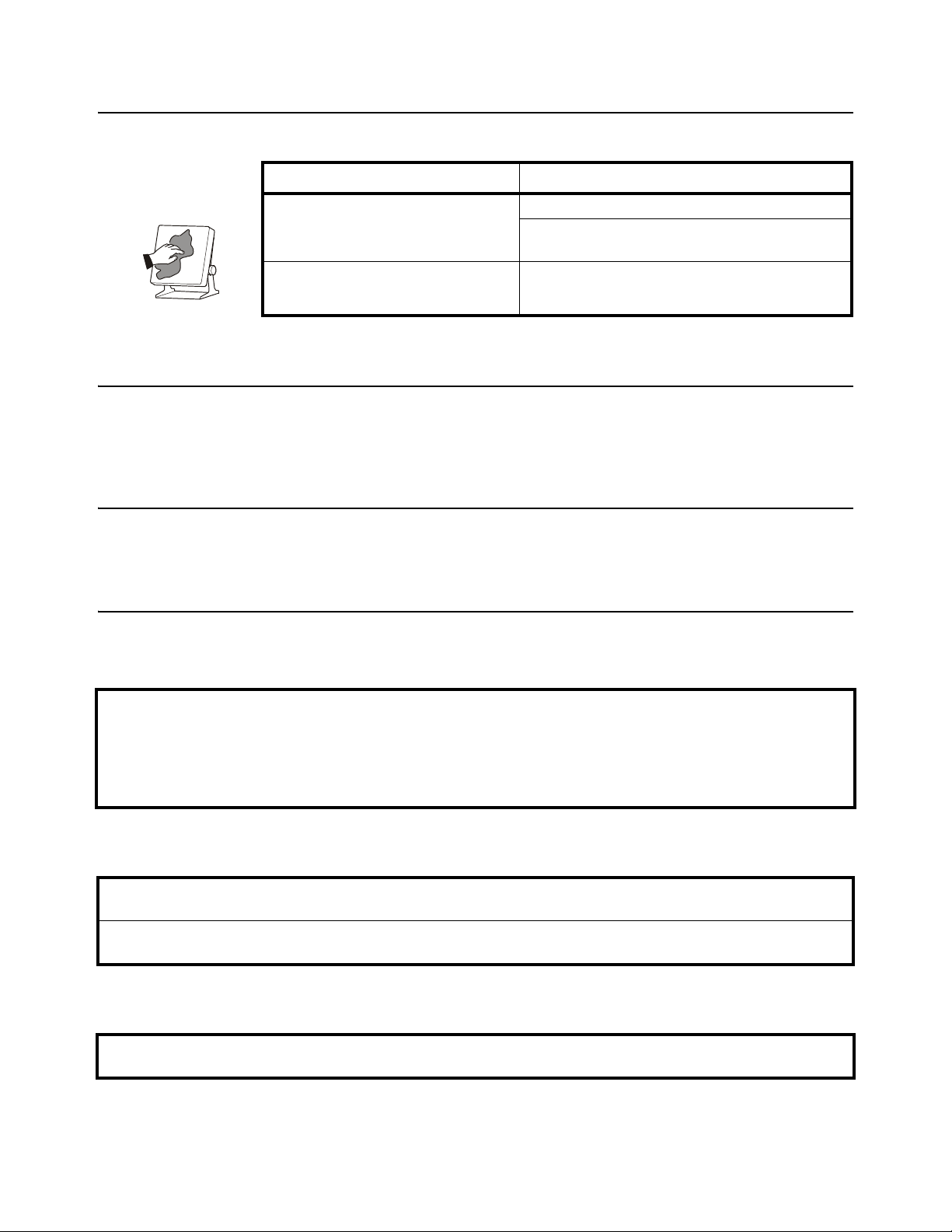
1.4 Cleaning the machine
Table 1.1 Cleaning DOs and DON’Ts
DO DO NOT
Wipe down the outside of standard products
with a clean cloth, moistened with water and
a small amount of mild detergent
Spray the cloth when using a proprietary
cleaning fluid
Attempt to clean the inside of the machine
Use harsh abrasives, solvents, scouring cleaners or
alkaline cleaning solutions
Spray any liquid directly on to the display windows
1.5 Training
Do not attempt to operate or complete any procedure on a machine unless you have
received the appropriate training or read the instruction books.
1.6 Sharp objects
Do not use sharp objects such as screwdrivers or long fingernails to operate the keys.
1.7 FCC and EMC declarations of compliance
United States
This equipment has been tested and found to comply with the limits for a Class A digital device, pursuant to Part 15 of the FCC Rules.
These limits are designed to provide reasonable protection against harmful interference when the equipment is operated in a
commercial environment. This equipment generates, uses, and can radiate radio frequency energy and, if not installed and used in
accordance with the instruction manual, may cause harmful interference to radio communications. Operation of this equipment in a
residential area is likely to cause harmful interference in which case the user will be required to correct the interference at his own
expense.
Canada
This digital apparatus does not exceed the Class A limits for radio noise emissions from digital apparatus set out in the Radio
Interference Regulations of the Canadian Department of Communications.
Le présent appareil numérique n’émet pas de bruits radioélectriques dépassant les limites applicables aux appareils numériques de
la Classe A prescrites dans le Règlement sur le brouillage radioélectrique edicté par le ministère des Communications du Canada.
European Countries
WARNING: This is a Class A product. In a domestic environment, this product may cause radio interference in which the user may be
required to take adequate measures.
Quick Balance User Instructions 7
Page 8
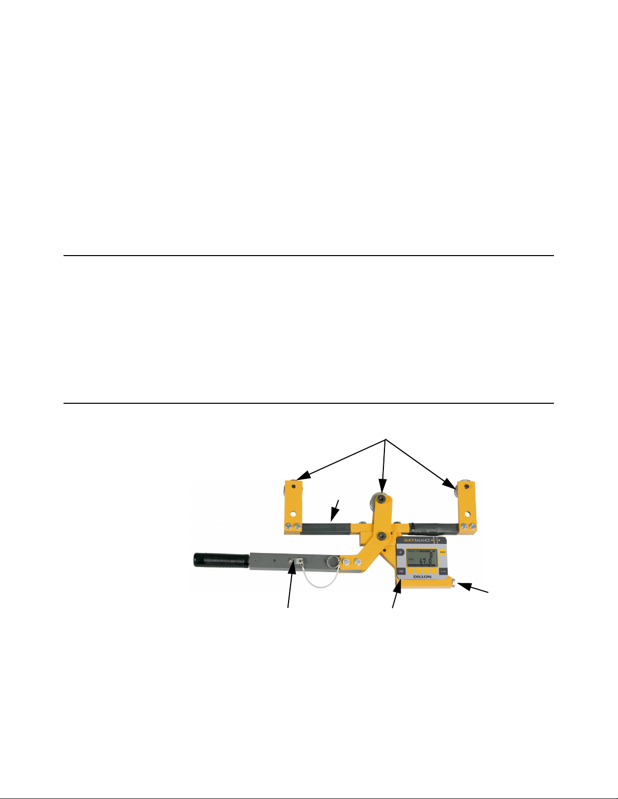
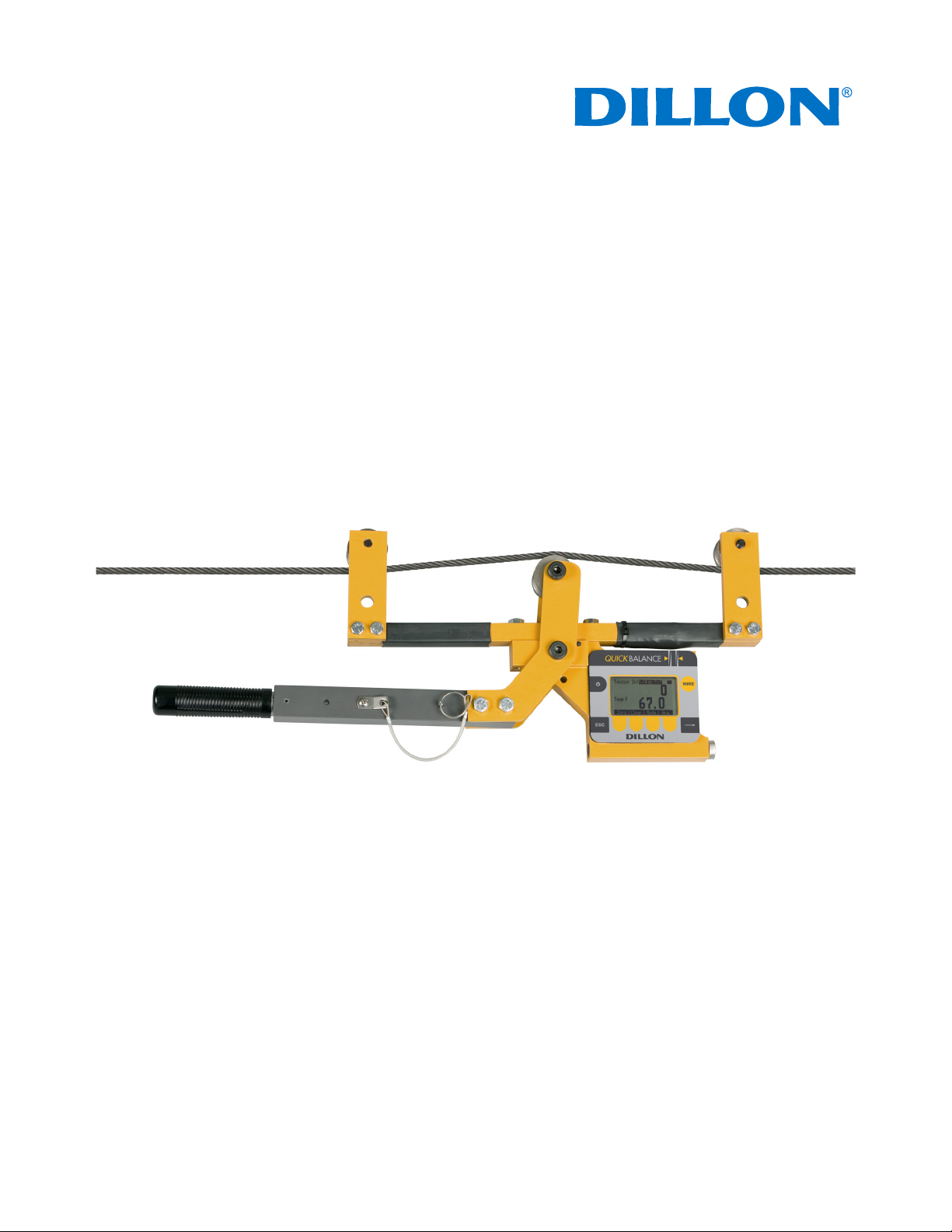
2 Introduction
Sheaves
Lever arm
Front panel
Battery
compartment
Support
arm
This manual covers the setup and operation of the Quick Balance Tension Meter from
Dillon. The Quick Balance is a simple, accurate strand dynamometer. It can be
clamped onto a cable, accurately determine the wire tension and be removed in
seconds.
The Quick Balance can handle multiple wire diameters, it can display live tension, dual
live/peak tension, average tension captured from several tests, dual tension/
temperature display and a check-tensioning graphical display.
With its battery-powered electronic interface, setup and operation is made simple with
on-screen prompts.
2.1 Unpacking
When you receive your Quick Balance, unpack it and inspect the container and the
instrument for any damage. Report any problems to the shipping company immediately
and save the packing materials.
Insert 2 ‘C’ batteries into the battery compartment, shown in Figure 2.1. Your Quick
Balance probably comes from the factory with the proper sheave size installed and
calibrated for your application. If not, follow the setup directions in Configuration Mode
on page 18 and Changing Sheaves on page 21.
2.2 Description
The Quick Balance is shown in Figure 1 with the parts labeled.
Figure 2.1 Front Panel and Keys
8 Quick Balance User Instructions
Page 9

The front panel of the Quick Balance is shown in Figure 2.2.
Figure 2.2 Quick Balance front panel
Following are descriptions of the keys and their functions:
ON/OFF key. Press this key to power up and turn off the Quick Balance.
ESC key. Press this key to escape an area of the menu or to clear the field when
in data entry mode.
WIRE key. Press this key to change the wire diameter you are testing with the
Quick Balance. Choose from the listed selection and when the desired size is
highlighted, press the ENTER softkey. Three standard sizes included:
1/2” 8 x 19
9/16” 8 x 19
5/8” 8 x 19
Five additional sizes may be added.
Softkey. Softkey function changes as needed for different tasks. The softkey
labels appear above the keys themselves. You will use these for operation and
configuration.
Arrow key. Press this key to reveal more softkeys in a group of softkeys.
Quick Balance User Instructions 9
Page 10

2.3 Important features
Quick to use Attaches and removes from tensioned line in seconds.
Direct tension readings No more complicated lookup charts! Save time and
Portable & rugged Designed for outdoor use.
Accurate Employs Weigh Bar
Multiple wire size storage Three standard sizes included:
Quick readout for ultra fast line tensioning.
improve accuracy.
®
technology used for precise
weighing.
1/2” 8 x 19
9/16” 8 x 19
5/8” 8 x 19
Five additional sizes may be added.
10 Quick Balance User Instructions
Page 11

3 Operation
Typical operation of the Quick Balance is covered below, followed by explanations of
the various display modes, how to change wire size, how to change the unit of
measure, etc.
3.1 Typical Operation
Take readings at three different places along the cable, moving the tension meter at
least four inches for each reading. Take the average of the readings. The built-in
average function is ideal for this task.
The handle quick release pin should be used when the Quick Balance is attached to a
cable that will be de-tensioned and retensioned. The pin prevents the handle from
opening once the tension falls to a small level. The pin should also be used if the
Quick Balance will be installed for a prolonged period.
To perform a typical tension measurement, see the note above and follow these steps:
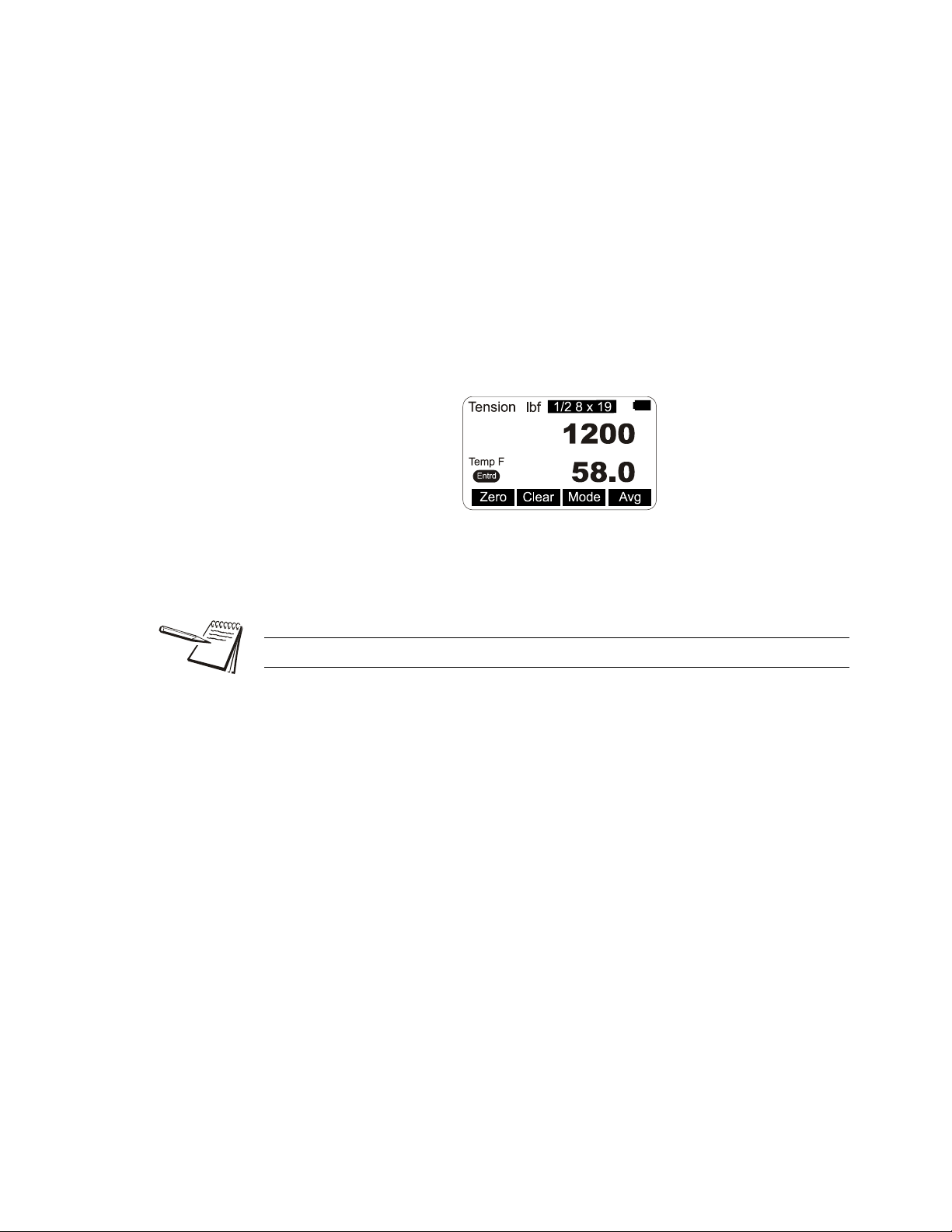
1. Turn the unit on by pressing the ON/OFF key…
The display shows DILLON briefly, then, in this example, the screen
shows the following:
Figure 3.1 Sample display
Press the WIRE key to list the stored calibrations.
2. This example shows the wire is a 1/2”, 8 X 19 stranded cable and the unit of
measure is lbf. Place the Quick Balance so the two outside sheaves hang on
the wire. Insure that the wire rope is riding in the groove of all three sheaves.
See Figure 3.2. Press the Zero softkey to zero the display.
0 should be displayed.
3. Raise the lever arm until it locks in the upright position to apply tension to the
wire. Read the line tension on the display.
Quick Balance User Instructions 11
Page 12

4. Release the lever arm and you are ready to perform another measurement.
Figure 3.2 Quick Balance attached to cable
3.2 Measurement Practices
For best measurement, install the Quick Balance at least 2 feet (0.6 m) from
terminations, clamps or other hardware. Do not install over the top of wire wrappings.
Take readings at three different places along the cable, moving the tension meter at
least four inches for each reading. Take the average of the readings. The built-in
average function is ideal for this task.
Do not apply tension greater than rated capacity of the instrument or overload
damage to the sensor may result.
Do not use the Quick Balance with cable larger than indicated on the sheaves.
Overload and damage to the instrument may result.
Do not mix sheave sizes. This will result in inaccurate measurement and possible
overload.
Do not use the Quick Balance to measure tension for wires if both of the following are
true:
1. No wire calibrations are stored of the same diameter as the wire you are looking
to measure, and
2. You do not have sheaves of the same diameter.
If both of these conditions exist, contact your Dillon distributor.
Contact your Dillon distributor to improve accuracy for a specific wire type by calibrating
to it.
Insure that the wire rope is riding in the groove of all three sheaves.
12 Quick Balance User Instructions
Page 13

Insure sheaves installed agree with sheaves noted in the Wire calibration. Exception:
Sheaves match the wire diameter of the cable to be measured and alternate calibration
is selected as per section Calibration to Specific Wire Type on page 22.
The Quick Balance has an internal temperature sensor inside the electronics cavity.
Dramatic temperature changes (such as moving from a warm vehicle to cooler
outdoors) requires time for the sensor to reach the same temperature. Direct sunlight
will heat the electronics cavity and cause higher readings than actual ambient
temperature. In these cases, use a seperate thermometer to determine temperature.
Be certain to enter this temperature into the Quick Balance if using the quick-tensioning
mode with the temperature dependent acceptance window.
For best tension accuracy, use the exact temperature of the wire. This may be widely
different from the ambient temperature if the cable has been sitting in direct sunlight.
3.3 Softkey Functions
Now that you’ve seen a simple operation, we’ll explain the softkey functions. Figure 3.3
shows the softkeys available during normal operation.
3.3.1 Top level softkeys
Zero Press this softkey to zero the force display. Press this at the beginning of
Clear Press this softkey and you are prompted to clear the Peak reading or the
Mode Press the Mode key to scroll through the five display modes. These are
Figure 3.3 Normal mode softkeys
a series of tension tests. You do not need to do it for every test unless there
is some zero drift.
Average. Make your choice by pressing the appropriate softkey and that
value is cleared from memory.
explained below:
Live Tension Mode: This is the default mode and it displays the live
tension.
Peak Mode: While in this mode, Peak is displayed on the screen. The
display shows the live tension on the top display and the peak force
achieved on the bottom display. To clear the peak remove any force on the
Quick Balance, press the Clear softkey and follow the prompts.
Balance Mode: While in this mode, Bal is displayed on the screen. This
mode allows you to capture the tension on two through 16 cables and
compare the readings.
Quick Balance User Instructions 13
Page 14

Temperature Mode: This mode shows the live tension in the top display
Display when tension is below
the dotted, target box.
Display when tension falls
within the dotted, target box.
and the current temperature in the bottom display. Also shown is whether
the reading is in Fahrenheit or Centigrade and if the temp is one that was
Entrd (entered) manually.
You can enter the temperature in one of two ways; let the Quick Balance
determine the ambient temperature automatically or key in a temperature
manually. Instructions for entering the temperature are under the Temp
softkey description.
Upper and lower thresholds for the Check-tensioning mode, discussed below, are set
in the Configuration WIRE menu.
Check-tensioning Mode: Check-tensioning mode permits quick & easy
graphical view of the applied tension versus the desired tension. This
mode works well when you are repeatedly tensioning to the same tension
range. This mode displays a bar graph representation of the tension being
applied. See Figure 3.4. The black bar represents the range of the wire,
from zero to ultimate wire rating. The wide white band is the tolerance
window based on upper and lower thresholds you can enter. The live force
is represented by the arrow and the white line on the black bar. When the
force gets within ±5% of the acceptance window, a close-up of the
acceptance window is displayed. See bottom example in Figure 3.4.
The Quick Balance has automatic tension targeting with temperature.
Points may be entered from a linear Tension-Temperature supplied table
for a wire cable. If entered, the check-tensioning window will automatically
float according to the active temperature (manual or automatic). Use the
bottom and top entries from the table. Patent is pending on this feature.
Figure 3.4 Check-tension display
To exit the check-tension mode, press any softkey to display the softkey
labels, then press the Mode softkey to scroll to the next mode. The next
mode is the first mode that was described, live tension mode.
14 Quick Balance User Instructions
Bal Press the Bal softkey to add a displayed tension to the average of other
entered readings. Follow the onscreen prompts.
Press the Right Arrow key to move to the next set of softkeys:
Page 15
Units Press this key to set the Quick Balance for displaying:
Temperature Display Mode
l Force in lbf, kgf or N
l Size of wire in inches or millimeters
l Temperature in Fahrenheit or Centigrade
Temp Press this softkey to choose the source of the temperature reading, the
Quick Balance itself (Meter), outside input (Input) or None. If you choose
Input, you are prompted to enter the temperature. When finished, press
the Enter softkey to accept this value.
Next you are prompted to choose Fahrenheit or Centigrade as the
temperature unit. When your choice is highlighted, press the Enter
softkey.
An annunciator shows when temperature has been manually entered. See
example below:
Setup Press the Setup softkey and you will see these choices; Bal, Off, About,
Misc and Test. These are described below:
Auto-off can preserve battery life.
Bal Press this softkey to perform a cable balance operation. You will
be prompted for information regarding the load such as the total
system weight and the number of cables being used to suspend it.
Off Press this softkey to enable or disable the auto-shutdown function.
If you choose Yes, you are asked to set a period of time in minutes.
Next, press the Enter softkey to accept this value. You are then
asked to set the shutdown type; Fixed, No Load, or No Change.
These are described below;
Fixed - The unit will shutdown after the set number of
minutes no matter what happens.
No Load - The unit will shutdown after the set number of
minutes only if there is no load on the unit. This
prevents shutdown in the middle of a test.
No Change - The unit will shutdown if there has been no keypad
activity or change in tension after the set number of
minutes.
Quick Balance User Instructions 15
Page 16

About Press this softkey to see the following information:
Device - Press this softkey to show a list of information about
the Quick Balance, such as -- serial number,
capacity rating, hardware and software revision
levels. Press any key to return to the previous
softkey set.
Calib - Press this softkey to show Calibration Points and
the calibration information for the current wire size.
Follow the on-screen prompts.
O. Load - Press this softkey to show an audit count of the
number of times the unit has been overloaded
beyond 125% of capacity. Press any key to return
to the previous softkey set.
Zero - Press this softkey to show the deadload anaylsis of
the Quick Balance. Press any key to return to the
previous softkey set.
Misc Press this softkey to set the following:
Flash - Enables or disables the momentary blinking of the
display to acknowledge a key press.
Zero - Enables the use of the Zero softkey to clear a peak
tension value.
Contr - Press this key to adjust the contrast of the LCD
display. Press the Up softkey to lighten the contrast.
Press the Down softkey to darken the contrast.
There is a keypad shortcut for increasing and
decreasing contrast. While in normal display mode
press and hold the Arrow key, then press and hold
the 2nd softkey simultaneously to increase contrast.
Press and hold the Arrow key, then press and hold
the 1st softkey simultaneously to decrease contrast.
Blite - Choose Blite to change the backlight operation.
You can increase or decrease the intensity (Inten)
or choose to turn the backlight on or off (Mode).
Test Press this softkey and the following softkeys appear:
Batt - Press this softkey to test the battery level.
A-D - Press this softkey to display the A to D counts.
Disp. - Press this softkey to perform a test of the display
pixels.
Keys - Press this softkey to test the keypad.
16 Quick Balance User Instructions
Page 17

Config This is a password protected menu. See Configuration Mode on page 18.
Press the ESC key to return to the normal operating mode. If you made changes to the
configuration of the unit, you are prompted to save them or abort the changes. Do so
and the unit returns to normal operation mode.
Quick Balance User Instructions 17
Page 18

4 Configuration Mode
4.1 Accessing the Configuration Mode
You need to access the Configuration mode to perform certain tasks. Access to some
of these tasks may be restricted by a supervisor password.
The Num keys increment and decrement the displayed numbers. The Adv key
moves the cursor to the next digit position.
Default Configuration password is 0. If a new password is lost or forgotten, contact
your Dillon distributor.
To access Configuration mode:
1. From normal operating mode, press the Right Arrow softkey…
A new softkey set, shown below, appears:
2. Press the Config softkey…
The following is displayed:
3. Use the Num and Adv keys to enter the Config password. Default is 0. After
the number is displayed, press the Enter key…
The following is displayed:
18 Quick Balance User Instructions
Page 19

4. The unit is now in the Configuration mode. To see the rest of the softkeys
available in this mode, press the Right Arrow key. All the Config softkeys are
shown below.
The softkeys in the Configuration mode are Wire, Setup, Reso, Mode, Units, Power,
ChPwd, and Reset. These are described below:
Wire Press this softkey and the wire selection screen is displayed. Choose an
existing wire to change its defining characteristics.
You are given a choice of changing the Range, which is used to set the
check-tensioning function, or the Rating, which is the maximum rating of
the cable.
Range - Press the Range softkey to set the range parameters for the
check tensioning display and follow the prompts to set the
following:
Low Temperature This is the lowest temperature at which the
device is accurate.
High Temperature This is the hioghest temperature at which the
device is accurate.
Units Set temperature scale (F or C)
Tension at Low This is the lowest acceptable force
Tension at High This is the highest acceptable force
Units Unit of measure used in defining the tension
limit (lbf, N, or kgf)
+/- Tolerance - Set the tolerance value.
Units - Set the unit of measure for the tolerance value
(lbf, N, or kgf)
Rating - Press this softkey and you are prompted to set the ultimate
rating for the cable being used and the unit of measure for that
rating (lbf, N, or kgf).
Setup Press the Setup softkey to view the Setup softkeys. This is the same as
the Setup softkey described in Top level softkeys on page 13.
Reso Press the Reso softkey and you are prompted to enter a display, or count-
by, resolution. Choose from Low, Medium or High. Medium is the default
value.
Low resolution provides the best stability and makes the display easiest to
read. High resolution provides the finest graduations, but sees greater drift
from wire creep and non-repeatability. If the reading is decreasing over
time or differing between measurements on the same line, lowering the
resolution will reduce these effects.
Mode Press this softkey to set the display mode on power up. Choices are
Force, Last, Temp,
Check, Bal, and Peak. Use the Sel keys to scroll
through the choices and press Enter to accept the displayed choice.
Quick Balance User Instructions 19
Page 20

Units Press this softkey to set the following:
l Unit of measure on power up. Choices are Last*, C2, C1, N, kgf, and
lbf. Use the Sel keys to display your choice and press Enter to
accept it. C2 and C1 are custom units. If you choose to have custom
units, you are prompted to enter the number of pounds in each
custom unit. The Quick Balance will then automatically calculate
correct display for the applied force.
Custom units of measure are handy when working with multi-part lines.
l Enable lbf - Enable or disable the pound-force unit of measure.
l Enable kgf - Enable or disable the kilogram-force unit of measure.
l Enable N - Enable or disable the N unit of measure.
l Enable CUST1 - Enable or disable the Cust1 unit of measure.
l Enable CUST2 - Enable or disable the Cust2 unit of measure.
l Enable C - Enable or disable Centigrade temperature.
l Enable F - Enable or disable Fahrenheit temperature.
Power Press this softkey to enable or disable the auto-shutdown. If you enable
this function you are prompted to set a period of time in minutes. Next,
press the Enter softkey to accept this value. You are then asked to set the
shutdown type; Fixed, No Load, or No Change. These are described
below;
Fixed - The unit will shutdown after the set number of minutes no
matter what happens.
No Load - The unit will shutdown after the set number of minutes only
if there is no load on the unit. This prevents shutdown in the
middle of line tensioning.
No Change - The unit will shutdown if there has been no keypad activity
or change in tension after the set number of minutes.
ChPwd Press this key and you are prompted to enter a new password to access
the configuration menus. Use the softkeys to scroll in a new password and
press the Enter softkey to accept it.
Reset Press this key and you are asked if you wish to reset the system. Press the
Yes softkey only if you want to reset the unit to factory default
configuration. Press the No softkey to abort this and return to the previous
screen.
Default password is 0. If a new password is lost or forgotten, contact your Dillon
distributor.
20 Quick Balance User Instructions
Page 21

5 Changing Sheaves
Screws
Do not use the Quick Balance with cable larger than indicated on the sheaves.
Overload and damage to the instrument may result.
Do not mix sheave sizes. This will result in inaccurate measurement and possible
overload.
As you use the Quick Balance on different diameter cables you must change to the
correct sheave size. To change sheaves, remove the hex head screws pointed out in
Figure 5.1 below. Replace the sheaves with the correct letter sheave and reinsert the
screws and tighten.
Insure sheaves installed agree with sheaves noted in the Wire calibration. Exception:
Sheaves match the wire diameter of the cable to be measured and alternate calibration
is selected as per the instructions in Calibration to Specific Wire Type on page 22.
Insure that the wire rope is riding in the groove of all three sheaves.
Figure 5.1 Changing sheaves
Quick Balance User Instructions 21
Page 22

6 Achieving Best Accuracy
6.1 Accuracy
The Quick Balance is an instrument designed to give accuracy that typically exceeds
normal requirements for wire tensioning. You should have an understanding of what
factors affect tension measurement accuracy.
6.2 Calibration to Specific Wire Type
While it is best to have the instrument calibrated to the specific wire size(s) and type(s)
used, the Quick Balance can often work adequately in other situations. If the best
tension accuracy is required, Dillon recommends that a calibration be performed for
that specific wire size and type.
Contact your Dillon distributor for any additional calibrations you may need.
6.2.1 What Calibration Choice and Sheaves Should I Use?
Situation Wire calibration selection Sheave selection Accuracy
Exact wire size and type is
shown in wire list
Wire size is same, but type
is not identical
Wire size is not the same Closest diameter Sheaves matching the wire size
Description of exact match Sheaves noted in list Best
Description of same wire diameter Sheaves noted for that wire size Good
being measured
Do not use the Quick Balance to measure tension for wires if both of the following are
true:
1. No wire calibrations are stored of the same diameter as the wire you are looking
to measure, and
2. You do not have sheaves of the same diameter.
If both of these conditions exist, contact your Dillon distributor.
Contact your Dillon distributor to improve accuracy for a specific wire type by calibrating
to it.
Fair
22 Quick Balance User Instructions
Page 23

6.3 Loading Error
A tensiometer works by deflecting the cable, which makes the cable path longer than
when a tensiometer is not installed. When the tensiometer is removed, the wire tension
decreases as the cable length is restored. This effect is known as loading error. The
Quick Balance design elongates the cable by a mere 0.08 inch (2 mm), making loading
errors extremely small.
6.4 Non-repeatability
The Quick Balance’s sheave with bearing design provides the best mechanical
performance. It is also superior at detecting tension that is being added or removed.
6.5 Non-linearity
Most three-point tension meters employ only linear characterization and have large
errors at the midpoints (up to 15%). The Quick check uses multi-point segmenting to
correct for non-linearity, reducing it to less than 0.2%.
6.6 Wire Characteristics
Creep Every material including steel exhibits creep under load. It will neck down
over time, quite quickly over the first few seconds and much slower as
time progresses. A wire cable also sees creep from the wire spacing and
wind. This effect is seen as a display that drifts lower after it has been
clamped in line.
Variations Material that varies in diameter or shape will have different output at the
same tension
Strands The best cable assembly is one that is perfectly round, as it will not
change contact geometry with the wire twist. The closer the wire cable
cross section appears to be round, the better the measurement
performance will be.
Quick Balance User Instructions 23
Page 24

7 Troubleshooting
Problem Possible Cause Solution
Powers on momentarily and turns off Low battery Replace with high quality alkaline batteries
Does not power on Low battery Replace with high quality alkaline batteries
Batteries installed backwards or no
spring contact
Software reset Remove battery cap & reinstall after one
Display contrast too light Hold the Right Arrow key down while pressing
Display is completely dark Display contrast too dark Hold the Arrow key down while pressing the F1
Display drifts downward once installed Wire material is creeping and internal
friction between wires is relieved.
Temperature not accurate Instrument changed temperature
environments
Instrument exposed to sun Enter temp manually
Insure that positive terminals of both batteries
(nub) face inward – towards the black cap.
Check that spring is attached to the battery
cap.
minute. Attempt to turn power on again.
the F2 key several times to increase the
display contrast. If nothing occurs, release both
keys. Press the power button and try again.
key several times to decrease the display
contrast.
This is normal behavior of wire. Lower display
resolution to mask this effect.
Allow instrument to remain in environment until
temp stabilizes or enter temp manually
24 Quick Balance User Instructions
Page 25

Page 26

AUTHORIZED DISTRIBUTORS
Ask the experts. Dillon distributors offer complete
service capabilities from application assistance to
sales and product support. Their experienced
representatives are the most knowledgeable
experts that you will find in the force measurement
industry. We recommend that you consult these
capable specialists for all of your measuring needs.
Overload Protection and
Overhead Weighing Equipment
Fairmont, Minnesota U.S.A.
Toll-Free: (800) 368-2031
Phone: (507) 238-4461
Fax: (507) 238-8258
www.dillon-force.com
 Loading...