

Page 1
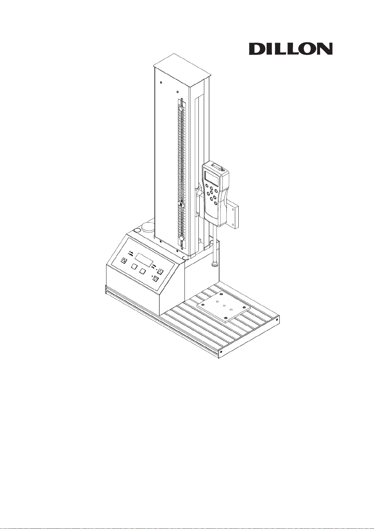
GTS-1000 Digital Control
Motorized Test Stand
Operator’s Manual
Page 2

TABLE OF CONTENTS
Introduction................................................................................................................................3
Safety and Equipment Precautions....................................................................................4
Set-up and First Configuration............................................................................................6
Register....................................................................................................................................6
Unpacking................................................................................................................................6
Setting up for your supply voltage.................................................................................6
Connect to power .................................................................................................................7
Selecting units-of-measure for speed...........................................................................7
Alignment ................................................................................................................................7
Mounting the force gauge.................................................................................................8
Getting Familiar with the GTS-1000 Testing Capabilities.........................................9
Working area..........................................................................................................................9
Column......................................................................................................................................9
Crosshead..............................................................................................................................10
Connectors ............................................................................................................................10
Operation...................................................................................................................................10
Front console........................................................................................................................10
Emergency stop button....................................................................................................12
Travel limits..........................................................................................................................12
Power switch........................................................................................................................13
Accessories................................................................................................................................13
Performing a Test...................................................................................................................14
Troubleshooting......................................................................................................................15
Specifications...........................................................................................................................16
2
3/07 Rev B
Page 3
INTRODUCTION
The motorized test stand is a tool to improve the quality of force testing results. It
helps attain the best testing repeatability by pulling or pushing at extremely consistent
speed in a direction in-line with the measuring device, such as a force gauge.
Motorized stands also improve ergonomics and testing throughput.
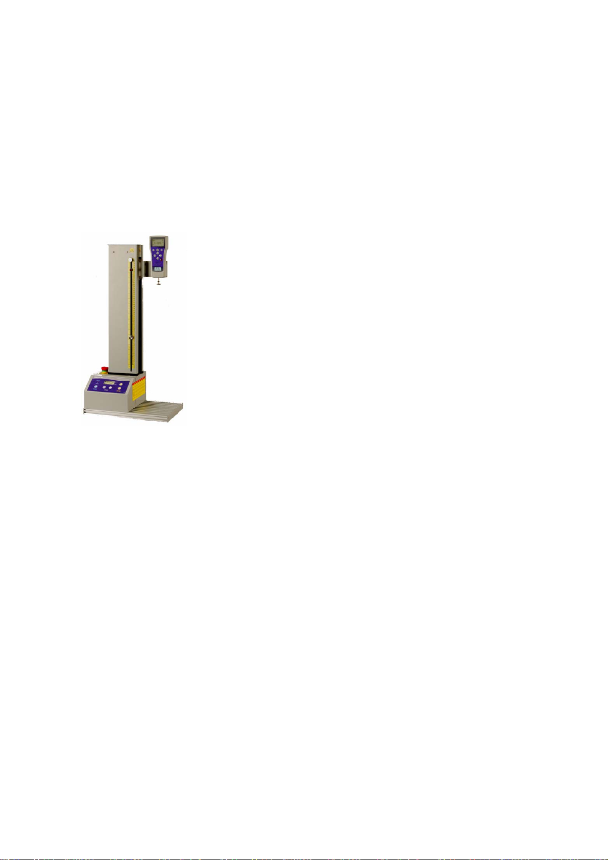
The Dillon GTS-1000 is a ball-screw driven digital test frame with capacity up to 1000 N
(220 lbf / 100 kg). The dimensions, speed range and capacity have been carefully
optimized to cover the test procedures and specimen sizes most often needed by
quality departments within many sectors of R&D and production
industry. Complemented by a Dillon force gauge, grips and
accessories, it constitutes a key component in force
measurement systems to accurately test a wide range of
products.
This tester may be used for tensile and compression tests of
many types (e.g. break, peel, flexural, top-load and many more).
The digital controls make testing speed more accurate and the
stand more intuitive to operate.
The crosshead features
the side-mounted controls and large working area, it can test large samples.
he Dillon GTX and GS force gauges are recommended for use with the GTS-1000 Test
T
Stand. It can accommodate other gauges with proper fixturing and alignment.
ith correct use your GTS-1000 will give many years of reliable service.
W
Please re
ad this operating manual thoroughly before attempting to operate
an adjustable generous 5 inch (127 mm) throat. Combined with
your GTS-1000 force tester.
3
Page 4

SAFETY & EQUIPMENT PRECAUTIONS
Read the instruction manual completely before attempting to use the
GTS-1000 Test Stand. By following the instructions contained in this manual, the
optimum accuracy and performance can be attained in the safest manner.
RISK OF PERSONAL INJURY! Samples under test can store large amounts of energy
which can be suddenly released upon sample failure. Sample failures can occur without
warning. Be certain the operator is protected from flying/ whipping parts from potential
high energy failures with some type of barrier.
Exercise extreme caution during testing or whenever the crosshead is moving.
ALWAYS Wear eye and face protection when testing.
NEVER place fingers inside the column!
NEVER place hands in vicinity of moving parts.
NEVER place hands near sample when subjected to load.
NEVER operate the GTS-1000 with the cover off.
RISK OF ELECTRICAL SHOCK! Do not remove cover. No user serviceable parts
inside. Refer servicing to qualified service personnel.
RISK OF ELECTRICAL SHOCK! Do not allow fluid to run into the T-slots. This can
reach the electrical circuitry. Tests with potential for running fluids should have a larger
plate secured to the T-slot work surface. Always unplug the stand immediately if fluid
runs into the T-slot and do not reconnect until all fluid is cleaned.
Verify Input Power Source BEFORE operation. The GTS-1000 may operate with
110V or 220V provided the Power Input Module is in the proper setting corresponding
to the source power. Always make sure that the supply power matches the setting on
the Power Input Module before connecting the power cord. Failure to do so will cause
serious damage to the tester.
Use Dillon GS/GTX force gauges. The GTS-1000 is designed to be used safely with
the Dillon GS/GTX force gauges.
Prevent overloads. Do not exceed capacity of the force gauge or stand (whichever is
lower). Stand capacity is dependent upon gauge attachment position. See rear of
crosshead. Damage from overload is not covered by warranty.
Watch for accidental contact. Loadcells and force gauges are delicate pieces of
equipment and can easily be damaged irreparably. Damage commonly results from the
4
Page 5

crosshead traveling downwards and running fixtures together. Take precaution to
minimize this situation.
Verify alignment. Be sure to align any lower fixture location in line with the attached
force gauge stem. The force must be applied in line for tests to be accurate and to
avoid gauge damage.
Understand all aspects of testing equipment operation before operating! See users
manual or contact your Dillon dealer with any questions.
5
Page 6

SET-UP & FIRST CONFIGURATION
Register:
Register your Dillon products at www.dillonforce.com.
Unpacking the GTS-1000
Upon receiving the unit please check for obvious physical damage to the packaging
material and the instrument itself. Be sure you have adequate equipment available to
safely lift the test frame from the packaging. Once removed from the packaging, place
the test frame on a stable, flat and level work surface. Inspect the machine for any
signs of obvious transit damage. If any damage is evident, or if any of the items listed
below are missing, please notify your Dillon distributor immediately.
GTS-1000 test stand with feet and two limit switch knobs
Tension plate and 10-32 short stud
This User’s Manual
Appropriate power cable
Allen key for side plates
Allen key for tension plate hardware
Two screws to mount gauge
If any damage is discovered do not go any further with installation and do not connect
the unit to a power supply under any circumstances.
We recommend you keep all packaging for future shipping requirements.
Setting up for your supply voltage
The GTS-1000 Power Module has two settings:
-110-120 VAC
-220-240 VAC
The GTS-1000 requires a stable, regulated AC power source.
Confirm your AC supply power matches the setting on the power supply module. Read
the voltage range at the bottom, next to the twin arrows –
see circled items on image. If this does not match, the power
supply module must be reversed. Carefully apply torque to
the slot located under the main connector jack with a flathead
screwdriver to open the power module. Pull out, flip over and
reinsert fully. You may need to lift a closing gate Make sure
the correct label is displayed at the bottom of the power entry
module and that the module is fully seated.
6
Page 7

CAUTION – Before connecting power:
1. Insure voltage setting on the stand agrees with
your supply voltage.
2. Insure the AC power is regulated.
Non-warrantable stand damage can result if not
followed.
If in question about your supply voltage or the stand voltage configuration,
contact your Dillon distributor before connecting to power!
Connect to power
After all the above points have been checked and confirmed to be correct, connect your
power cord and power the GTS-1000 on. The power switch is at the rear of the stand
right above the power cord. The console will illuminate indicating the machine is ready
for use.
WARNING
The power supply for the test frame must have a
third-wire earth ground. Connecting the test frame to
an outlet without an earth ground produces potential
for dangerous electrical shocks.
Selecting units-of-measure for speed
The GTS-1000 displays speed in inches per minute or millimeters per minute as shown
by the LED annunciator. To toggle the units, press and speed keys simultaneously.
Although easily changed, this parameter is generally set only once by most users.
Alignment
Proper alignment is important for testing accuracy and to prevent damage to the stand,
gauge and fixtures.
1. Load cell alignment with the stand structural columns. The GTS-1000
has a wide range of force gauges it can accommodate. However adapter plates
and other hardware must be designed to insure the load cell stem extends no
more than 28 mm in front of the crosshead. This is essential to prevent twisting
loads to the frame, which can cause irreparable stand damage. See “Mounting
the force gauge”.
2. Load cell stem alignment with lower fixture (tension tests). This is key
for accuracy and to prevent damage to the gauge. Adjust lower tension plate
hardware/fixturing to bring into alignment with load cell stem.
7
Page 8

Mounting the force gauge
For long stand life, the gauge must be mounted so the load cell stem is in-line with the
center of the internal columns. The standard GTS-1000 crosshead accommodates
gauges that measure between 8 – 28 mm from the back of the gauge to the load cell
stem center AND have 57 mm twin vertical hole spacing.
ll GS/GTX Series gauges mount directly to the GTS-1000 tester in perfect alignment
A
with the tester columns. Use included screws to secure.
another force gauge will be mounted, discuss mounting with your Dillon dealer.
If
CAUTION
When using a force than a Dillon GS or gauge other
GTX, it is the installer’s responsibility to ensure:
1 . strength of all connections and insure hardware
mounting depth falls within gauge manufacturer
requirements, and
2. load cell stem columns within is centered on the
GTS-1000 specifications.
Choose the gauge mounting position on the crosshead noting the maximum rated stand
capacity at that position. Secure with two screws insuring maximum depth for gauge is
not exceeded.
8
Page 9

GETTING FAMILIAR WITH THE GTS-1000 CAPABILITIES
Working area
The GTS-1000 Series features a large working area ideal for testing large samples up to
10.2 inches (260 mm) wide. The versatile T-slots can secure unusual shaped fixtures
or parts in tension. T-nuts and screws may be used to secure other fixturing.
Do not allow fluid to run into the T-slots. Tests with potential for running fluids should
secure The Dillon oversized plate accessory (available separately) to the T-slot work
surface and remove the side T-slot cover plates. Always unplug the stand immediately
if fluid runs into the T-slot and do not reconnect until all fluid is cleared and dried.
The GTS-1000 includes a handy tension base plate for in-line tension
grips as well. To remove or install, remove one cover plate side
screw and loosen the other. Rotate cover 90 degrees. Slide tension
plate with T-nuts loosely attached in or out as desired. Rotate cover
back and retighten screws.
Column
The GTS-1000 Series is a single column stand designed for vertical use. Maximum
crosshead travel is 18.7 inches (475 mm).
The GTS offers exceptional working headroom of 22.8 inches (580 mm) with the GTX or
Do not allow fluid to run into the T-slots. This can
produce an electrocution hazard. Always unplug the
stand immediately if fluid runs into the T-slot and do
not reconnect until all fluid is dried.
WARNING
GS force gauge. Over 5 inches (125 mm) of extra headroom reduces travel loss impact
due to fixturing. Extension rods may be required for short samples with low profile
fixturing. In compression, blocks may be used to elevate the sample as needed.
9
Page 10

Crosshead
The crosshead has six mounting holes for attaching a gauge with twin 2.25 inch (57
mm) hole spacing. The maximum stand capacity is dependent upon which position the
force gauge is mounted to.
Gauge mounting position Throat opening Maximum stand capacity
A (closest to column) 2.64 inch / 67 mm 1000 N / 220 lbf / 100 kgf
B (middle) 3.82 inch / 97 mm 750 N / 165 lbf / 75 kgf
C (furthest from column) 5.00 inch / 127 mm 500 N / 110 lbf / 50 kgf
Connectors
Three 15-pin connectors are on the rear of the stand.
Position Use
Top (n/c) No connection. Factory and dealer use only.
Middle (GTX) Connect to a Dillon GTX force gauge for stand reverse/stop control
on sample break or compression overload.
Bottom (PC) Sends the GTX serial information to a computer when the stand
reverse/stop cable above is used.
expansion boxes required by other brands.
OPERATION
Overview of controls
The GTS-1000 front console has three basic
sections:
#1 Operating mode
#2 Test speed
#3 Move
Additional controls include:
- Emergency stop button (above console)
- Crosshead travel limit switches (on column)
- On/off power switch (at rear of stand)
The PC port eliminates Y-cables or
10
Page 11

#1 Operating MODE
The GTS-1000 has two operating modes, marked by an LED on the console. Press to
cycle between:
1. Manual. Once UP or DOWN is depressed, the crosshead moves until any of the
following occurs:
a. Either MOVE key is pressed
b. A limit switch is tripped (in the appropriate direction)
c. The emergency stop button is pressed
2. Auto-reverse. This mode can speed up your repetitive batch testing. It runs at
test speed until it reaches the travel limit and then automatically reverses,
traveling at wide open throttle back to the other limit switch. You can stop the
stand at any time by pressing the UP or DOWN key or Emergency Stop button.
CAUTION
Auto-reverse mode is not suitable for tensile testing
when the sample must be removed before lowering,
such as ductile metal parts.
The Dillon GTX force gauge offers increased stand control.
- In Manual mode, the GTX can stop the stand upon sample break detection.
- In Auto-reverse, it can reverse the stand upon sample break detection.
The GTX also interrupts downward travel when gauge capacity is exceeded to reduce
potential for overload.
See accessories for the GTX stand reverse cable.
CAUTION
The overload detection within the GTX is intended as
a backup approach to help reduce accidental
overloads under slow speeds. The GTX must NOT be
the primary method to prevent overload.
#2 Test SPEED
The GTS-1000 features speed selection keys and a speed display. The and keys
adjust the crosshead speed shown on the LED display. The speed adjustment is slow
initially, but then increases the rate when held down.
Speed may be adjusted while stopped or while moving. Full speed return in autoreverse mode is not adjustable.
WARNING
Take care when adjusting speed up while crosshead
is moving. Speed may rapidly increase.
11
Page 12

The speed unit of measure is shown by an LED at right of window, either in/min or
mm/min. To toggle between the units, press and keys at the same time.
#3 MOVE Crosshead
The GTS-1000 crosshead travel is controlled by the MOVE Keys.
To begin the crosshead in an UPWARD direction, depress ×.
To begin the crosshead in a DOWNWARD direction, depress Ø.
The corresponding LED is lit while the stand is moving.
The crosshead will not move in a given direction if it is against a limit switch stop.
CAUTION
The GTS-1000 is an extremely quiet stand in
operation and others may not be aware when the
stand is moving. The operator must remain
monitoring when crosshead is in motion.
PRECAUTION
To avoid accidental crosshead movement, power off
the stand or engage the emergency stop when
unattended.
To stop a moving crosshead press either × or Ø key or the emergency stop button.
Emergency stop button
The GTS-1000 Series features an emergency stop button conveniently located at the
top of the console. This can be used as a panic switch whenever conditions are
becoming a concern. Engaging the emergency stop is also a good precaution to avoid
inadvertent crosshead movement when the stand is unattended.
When emergency stop button is depressed, motor control is removed from the tester.
The crosshead will stop, all annunciators light and “Stop” is displayed in the speed
window. To activate, press firmly downward. The stop button will latch and lock into
position.
To release the emergency stop button, gently turn in a clockwise direction. This will
disengage the lock and return the stop button to its normal position. You will see a
green band below the red stop button and the speed will return to normal display. The
stand will remain stopped until × or Ø is depressed.
Travel limits
The GTS-1000 Series has two adjustable mechanical travel limits that restrict the
working travel range of the stand.
12
Page 13

- Travel limits help protect your stand and force gauge from overloads by
preventing fixturing from contacting when the crosshead is moving.
- Limits improve testing convenience by stopping at convenient test start and stop
points.
The crosshead will stop moving (or automatically reverse) when the crosshead comes in
contact with a travel limit. You need to adjust these limits to your equipment and test
to attain the benefits.
To adjust, turn knob counterclockwise ½ to 1 turn. Gently lift or lower limit switch to
the desired stopping point. (TIP: keep the knob face as plumb as possible for easiest
sliding.) Snug the knob clockwise to lock and confirm proper stopping point by slowly
moving the crosshead and checking where it stops.
On/Off switch
The GTS-1000 Power On/Off switch is located at the power entry module at the rear of
the stand. When turning the machine OFF, it may take about 15 seconds for the speed
indicator display to extinguish while the internal capacitor self-discharges. Do not turn
power back on until the front panel lights have extinguished.
The console lights require about 15 seconds to completely
discharge when the power is turned OFF.
NOTICE
ACCESSORIES
Force gauges – many styles and capacities available from Dillon.
Software – provides more information about tests and eliminates entry
errors.
Adapter plate – accommodate other gauges with different hole spacing.
GTX stand reverse cable – offers additional stand control with the GTX
force gauge.
Extension rods – for short/thin sample testing without using blocks.
Oversize working plate – increases depth for large samples and/or increases
protection when fluid leakage may occur during testing.
Quick-couplers and adapters – change grips in seconds. Can also
join two differently threaded items quickly and affordably.
13
Page 14

PERFORMING A TEST
Force testing is fairly easy and consistent with a little experience. It generally consists
of:
a) Attach the appropriate testing fixtures to the gauge.
b) Attach the appropriate testing fixtures to the base.
c) Ensure fixtures are in alignment.
d) Position lower travel limit switch so fixtures cannot contact each other.
e) Start software package such as Q-Graph or Q-Data.
f) Secure your sample to the fixture on the gauge.
g) Zero and reset the force gauge peaks.
h) Lower the crosshead and secure sample to the lower fixture.
i) Add barrier if projectile pieces may fly.
j) Reposition lower travel limit at convenient test starting point.
k) Note the starting crosshead measurement on the ruler.
l) Adjust test speed.
m) Check manual or auto-reverse mode.
n) Start test with × or Ø key.
o) Note crosshead measurement at point of interest.
p) Save/print Q-Graph report or send peak gauge reading to Q-Data.
q) Crosshead Return for new sample – start again at step f.
Some steps are optional depending upon test type and the information being sought.
Most force gauges will retain the peak force for the test, which is generally considered
strength or effort to break the item.
The GTX Series break detection function will send a stop /reverse signal to the stand
upon sample break detection. Requires a cable connection between the GTX and GTS-
1000. Be certain to press RESET after each test to clear the peak values and ready the
gauge for the next test.
14
Page 15

TROUBLESHOOTING
Behavior Problem Action
No lights on front panel Power switch off Turn on power switch on
rear of stand
Power not connected Insure cord is secure at
both ends and has supply
power
Power setting Verify supply power and
power module setting
Stand does not move Limit switch Attempt movement in other
direction.
Release limit switch.
Emergency stop Release emergency stop
button.
Stand moving at wrong
speed
Stand does not reverse at
limit
No reverse upon sample
break with GTX
GTX configuration Set break detect and verify
Gauge not in alignment
with fixture
Grinding noise
Non smooth movement
Struggling motor
Console lights remain on
after power down.
Incorrect speed unit-ofmeasure (in/min or
mm/min)
Manual mode selected Change mode to auto-
Prior test peaks not cleared Press RESET on the GTX
Alignment adjustments See ‘Alignment’ section of
Stand may have been
overloaded or other
problem
Normal Allow 20 seconds for
Press and together at
the same time to change
units of speed
reverse
prior to starting each test
peak reading is larger
manual
Contact your Dillon dealer
capacitor to discharge and
lamps to extinguish.
Contact your Dillon dealer if these troubleshooting steps do not take care of the
condition.
15
Page 16

Specifications
Gauge mounting position Throat opening Maximum stand capacity
A (closest to column) 2.64 inch / 67 mm 1000 N / 220 lbf / 100 kgf
B (middle) 3.82 inch / 97 mm 750 N / 165 lbf / 75 kgf
C (furthest from column) 5.00 inch / 127 mm 500 N / 110 lbf / 50 kgf
Power consumption: 150 watts maximum
Stand weight: 54 lb / 25kg
Travel range: 18.7in / 475 mm
Maximum headroom: 22.8 in / 580 mm
Working area: 10.2 x 10.2 in / 255 x 255 mm
Tension plate: Three 10-32 UNF holes
Speed range: 0.2 – 40.0 in/min ; 5 – 1000 mm/min
Speed display: Digital LED
Direction of travel indicated on stand: Yes
Operating modes: Manual and auto-reverse
Reverse on sample break: Yes, with GTX and cable
Reverse on compression gauge overload: Yes, with GTX and cable
16
 Loading...