

Page 1
GS Series User’s Manual
Page 2

Table of Contents
Table of Contents…………………………………………………………… 2
Introduction…………………………………………………………………… 3
Before Use…………………………………………………………… 3
Operation Overview…………………………………………… 3
Powering the GS………. ………………………………………………… 4
Using the GS…………. ……….…………………………………………… 5
Fitting Accessories……………………………………………… 5
Mounting to a Test Stand…………………………………… 5
Powering up………………………………………………………… 5
Basic Functions…………………………………………………… 6
Main Menus……………………………………… ………………… 10
AUTO-OFF………………………………………………… 10
PASS-FAIL………………………………………………… 11
MEMORY…………………………………………………… 12
CALIBRATION…………………………………………… 13
DIAGNOSTIC…………………………………………… 13
ABOUT……………………………………………………… 14
Measurement Practice………………………………………… 15
GS Specifications……….………………………………………………… 16
Conversion Factor…………………………………………………………… 17
GS series User’s Manual REV 2.1 22/01/12
2
Page 3

Introduction
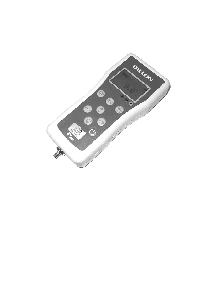
Thank you for choosing the Dillon GS series instrument. With
correct use and regular re-calibration it will give many years of accurate
and reliable service.
The GS can measure tensile and compressive forces accurately,
while being simple to use by the operator. It may be used handheld or
mounted top a fixture or test stand.
Software and accessories are available to make your force gauge
even more versatile. Ask your distributor for additional information.
Before Use
Upon receiving the unit please check that no physical damage
has occurred to the packaging material, plastic case or the instrument
itself. If any damage is evident please notify Nextech immediately.
Operation Overview
The most commonly used features (such as displaying force,
peak hold, zero and changing of displayed units) can all be done by
pressing a single dedicated key identified on the font panel-see the Basic
Functions section.
You can press a menu key to access the gauge configuration- see
the Main Menu section.
3
GS series User’s Manual REV 2.1 22/01/12
Page 4
Powering the first time
The GS is supplied with a set of 4 Nickel Metal Hydride AA
rechargeable batteries. For safety reasons during transportation the
batteries are shipped discharged. To obtain maximum battery life we
recommend that you charge them with the charger/adaptor supplied for
at least 14-16 hours when you first receive the instrument.
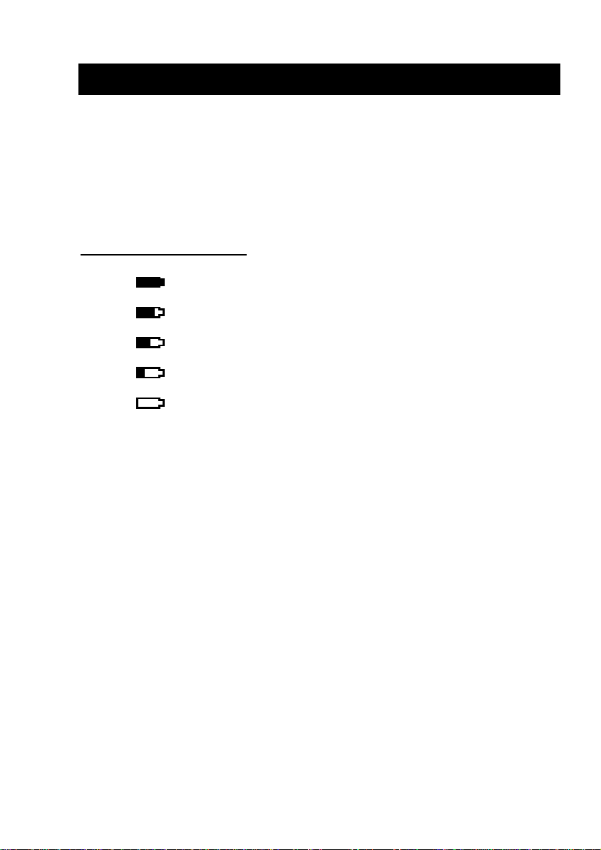
Battery Indicator
Battery level > 5.0 V
5.0 V > Battery level > 4.9 V
4.9 V > Battery level > 4.8 V
4.8 V > Battery level > 4.7 V
Battery level < 4.7 V
If battery level is less than 4.6 V, The “ battery empty” message
will be displayed and the gauge will power down automatically.
Important: Only use the adaptor/charger supplied.
GS series User’s Manual REV 2.1 22/01/12
4
Page 5
Using the GS
Fitting Accessories
Couple fittings directly to the load cell stem or use an extension
rod. The threads are 5mm and have capacities up to 2500 N.
Ensure that fixturing does nor contact the force gauge case.
Ensure that anything coupled to the gauge is screwed finger-tight
only. Excessive torque can damage the load cell and is not covered by
warranty.
Mounting to a Fixture or Test Stand
Use the two 10-32 threaded holes. The distance between the
holes is 2.5 inch. Or fours 3mm thread holes on the rear of the gauge
can be used for mounting the gauge. A versatile stand mounting plate is
available to couple the force gauge to many brands of test stands.
Powering up
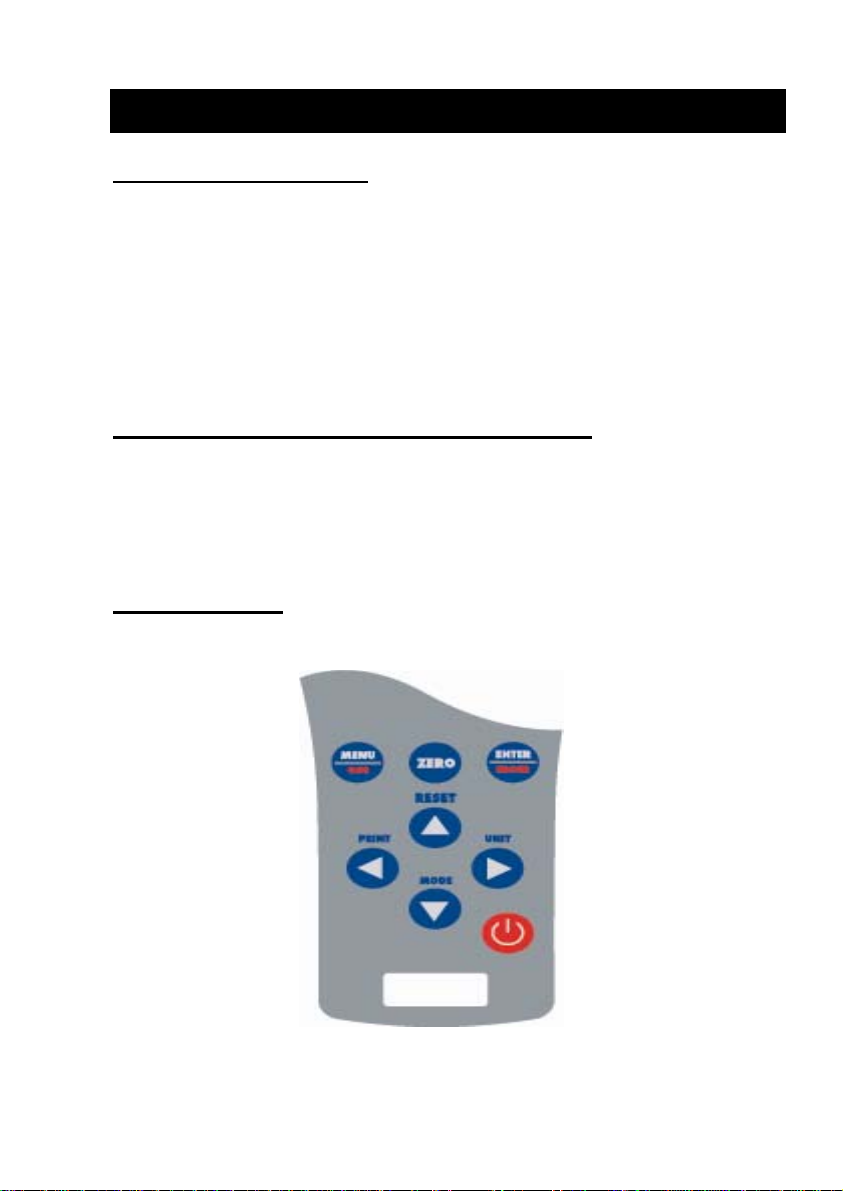
As show in Figure 1 the control panel has eight keys.
Figure 1 GS control panel
5
GS series User’s Manual REV 2.1 22/01/12
Page 6
To power up the gauge press the ON/OFF key. A short self-test
runs during which the display will show the capacity in Newton.
After the self test, providing no load has been applied to the
instrument, the display will show all zeroes. This is because the gauge
re-zeroes itself during the self-test routine.
*If a force is applied via the load cell probe (hole at bottom of
GS), the reading on display will register the applied force.
*Forces may not show zero if it is moved during the self test
routine. Once it is properly mounted and zeroed the reading will be
stable.
*Do not overload the load sensor. This will cause irreparable
damage. Forces greater than 120% of full-scale will produce an audibl e
beep and OL symbol will blink on the display until load is release and
RESET key is pressed.
To power down the gauge press the ON/OFF key.
*All the current settings are saved when the gauge is turned off
and the gauge will function in the same mode when powered up again.
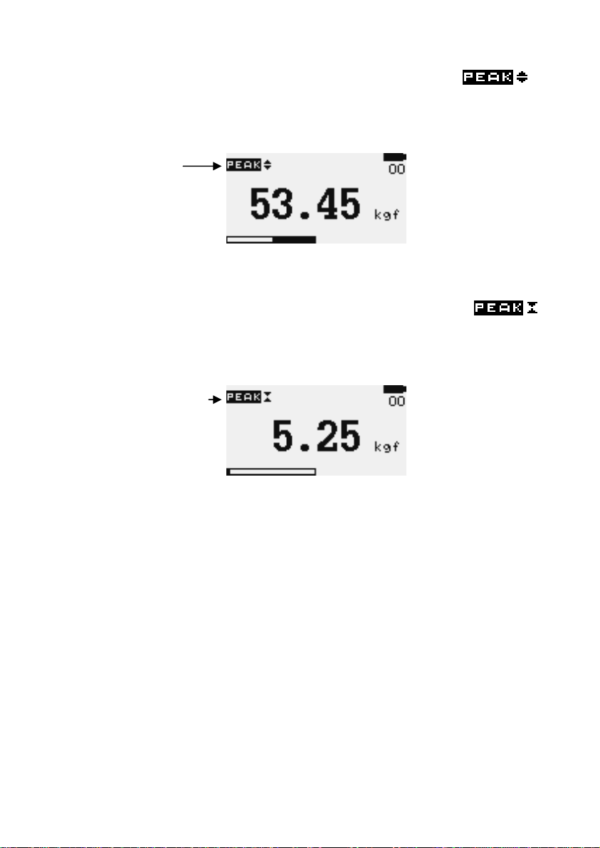
Basic Functions
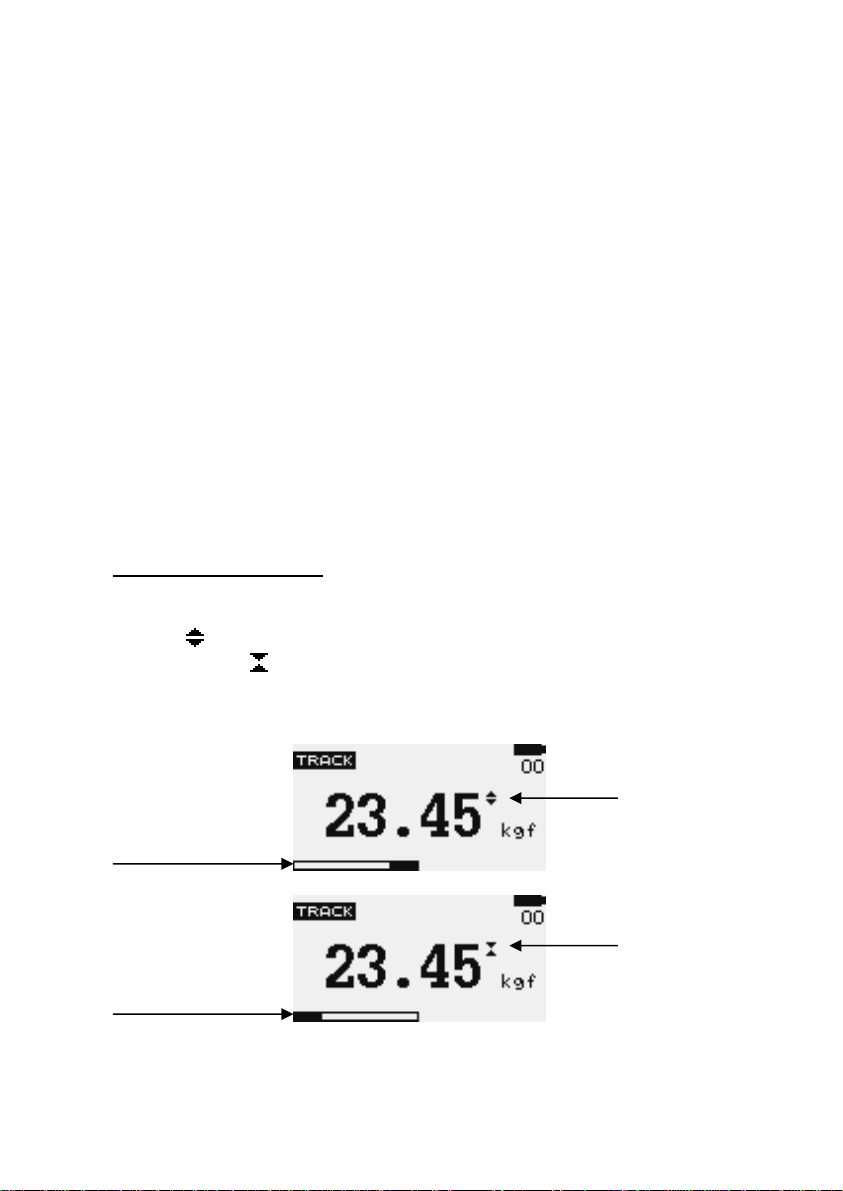
Tensile forces are displayed on the GS and recognized by the
symbol
by the symbol
Display of Tension/Compression
Tension
symbol
Load indicator
bar of tension
Compression
Load indicator symbol
bar of
compression
, Compressive forces are displayed on the GS and recognized
Figure 2 Tension and compression displays
GS series User’s Manual REV 2.1 22/01/12
6
Page 7

A load indicator bar alerts the operator to how much load has been
applied to the load sensor.
For tensile force the indicator bar is move from right to left. For
compressive forces the indicator bar is move from left to right.
Zeroing the gauge During the operation of the gauge it is often
necessary to zero the display – e.g. when you wish to tare out the weight
of a grip, so it does not become part of the measured reading. Press and
release the ZERO key.
Changing the unit of measure You can choose from the following
units of measure depending on the capacity of your gauge:
milliNewtons, kiloNewtons, Newtons, gram-force, kilogram-force, ounceforce or pound-force.
To change the display units press the UNITS key. Each
successive key press will select the next available units until the gauge
returns to its original setting. The GS automatically converts readings as
new unit of measure are selected.
*Note: All units may not be displayed depending on gauge capacity.
Changing the mode of measure You can choose from the following
modes of measure: Track, Peak-Tension, and Peak-Compression,
To change the display mode press MODE key. Each successive
key press will select the next available modes until the gauge returns to
its original setting.
Track mode Press MODE key until the
on the display. The display will now indicate forces applied in both
directions as they are applied to the load sensor and maintain the live
display. See Figure 3a
Track symbol
Figure 3a Track
7
GS series User’s Manual REV 2.1 22/01/12
appeared
Page 8
Peak-Tension mode Press MODE key until the
appeared on the display. The display will show the maximum tensile
force. See Figure 3b
Peak Tension
symbol
Figure 3b Peak Tension
Peak-Compression mode Press MODES key until
appeared on the display. The display will show the maximum
compressive force. See Figure 3c
Peak Compression
symbol
Figure 3c Peak Compression
Resetting the gauge Press RESET key to clear both maximum
registers and prepare for detecting the next maximum readings.
Backlit Display When you press any key or applied forces to load
sensor greater than 0.5 % of full scale the backlight will go on for 60
seconds.
Invert Display The display may be inverted or “reversed”, so that the
operator can read it more comfortably. Press and hold the MENU key
while powering up the GS to invert the display. This feature is
remembered after power down. Perform the same steps again to restore
the display to the opposite direction
GS series User’s Manual REV 2.1 22/01/12
8
Page 9

Saved reading to memory Any reading can be saved anytime by
press MEM/ENTER key. A total of 500 readings can be stored in the
database include the reading unit.
Computer Control of Force Gauge A computer can control the force
gauge by sending USB commands.
USB Command Action
“m” Changing measure mode.
“u” Changing measure unit.
“z” Zero the gauge.
“r” Reset the gauge.
RS232 output signal The displayed reading may be transmitted to PC
by pressing the PRINT key or sending request command from PC to the
gauge
USB command Action
“l” Send live reading value with unit.
“p” Send peak tension value with unit.
“c” Send peak compression valu e with unit.
“x” or pressing
PRINT key
“d” Send memory
“!” Send information of gauge (model, capacity,
Send live reading value with unit, if current
mode is track mode.
Send peak tension value with unit, If current
mode is peak tension mode.
Send peak compression value with unit. If
current mode is peak compression mode.
serial number, firmware revision, original
offset, current offset, overload count).
9
GS series User’s Manual REV 2.1 22/01/12
Page 10

Main Menu
Press MENU/ESC key to access the main menu. To move
between the option listed on the main menu page, press UP and DOWN
arrow keys to move the cursor. Press ENTER to select the sub-menus,
activate feature and enter values. Within sub-menus UP, DOWN, LEFT
and RIGHT arrow keys will also change numerical values. Press ESC to
return to the main menu page.
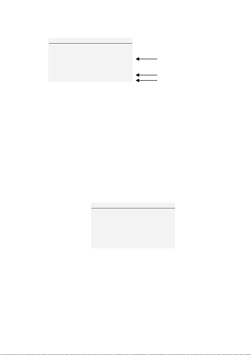
1) AUTO-OFF Press the MENU key, the display will show main menu
page and use UP and DOWN to move the cursor point to AUTO-OFF.
Press the ENTER key. The display will show the Auto-off menu page.
Press ESC key to return to the main menu page.
An Auto-off feature can be enabled to conserve bat tery power
where the gauge powers down after 5,10 and 15 minutes (depend on
Auto-off time) since the last key press. The AO will appear in the main
display if you activate this feature.
Use UP and DOWN key to move the cursor. Press the ENTER key
to select auto-off option and return to main menu page.
MAIN MENU
1) AUTO-OFF
2) PASS-FAIL
3) MEMORY
4) CALIBRATION
5) DIAGNOSTIC
6) ABOUT
Figure 4 Main Menu
AUTO-OFF MENU
1) OFF
2) 5 MINUTE
3) 10 MINUTE
4) 15 MINUTE
Figure 5 Auto-Off Menu
GS series User’s Manual REV 2.1 22/01/12
10
Page 11

2) PASS-FAIL the Pass-Fail feature used to set a defined acceptable
maximum and minimum forces gap for measuring. It activate by setting
the lower level and upper level forces limit If the forces value is within
the gap level, the display will show message PASS. Any reading values
outside this gap (higher or lower), the display will show message FAIL. If
you activate this feature the PF symbol will display on main display.
To access PASS-FAIL menu, Press UP and DOWN to move the
cursor point to PASS-FAIL and press the ENTER key the display will show
the Pass-Fail menu page. Press ESC key to return the main menu page.
PASS FAIL MENU
UPPER = 2.5 N
LOWER = 1.0 N
Press ‘Zero’ key to
Clear both value.
Figure 6 Pass-Fail Menu
Use LEFT ARROW keys to move cursor point to the desired value.
Use UP and DOWN keys to change the value, press and hold to scroll
values. Use RIGHT ARROW key to change the unit. Press ENTER to save
setting and return to main menu page.
*Pass-Fail feature will automatically disabled if you set LOWER
and UPPER = 0 N.
*LOWER must be less than the UPPER.
example LOWER LEVEL = 0 N, UPPER LEVEL = 20 N
Load
The “UPPER” LED will ON. Another LED OFF. Analog Out = 0V
Upper level
The “OK” LED will ON. Another LED OFF
Time
Figure 6a
11
GS series User’s Manual REV 2.1 22/01/12
Page 12

example LOWER LEVEL = 20 N, UPPER LEVEL = 0 N
Load
The “OK” LED will ON. Another LED OFF. Analog Out = 2V
Lower level
The “LOWER” LED will ON. Another LED OFF.
Time
Figure 6b
example LOWER LEVEL = 10 N, UPPER LEVEL = 20 N
Load
The “UPPER” LED will ON. Another LED OFF. Analog Out = 0V
Upper level
The “OK” LED will ON. Another LED OFF. Analog O ut = 2V
Lower level
The “LOWER” LED will ON. Another LED OFF. Analog Out = 0V
Time
Figure 6c
3) MEMORY This use to view the saved record, delete current record,
delete all record and print data of the saved record.
To access MEMORY menu, go to the main menu page press UP
and DOWN to move the cursor point to MEMORY and press ENTER key
the display will show the memory page. Press ESC key to return to main
menu page.
GS series User’s Manual REV 2.1 22/01/12
12
Page 13

Figure 7a Memory Page
Press UP and DOWN to change memory page, press and hold to
scroll change memory page. Press PRINT key to print the memory to the
serial port. Press ZERO key to access the DELETE menu.
DELETE ?
1) NO
2) DELETE
3) DELETE ALL
Figure 7b Delete last Menu
Press UP and DOWN to select the delete option , If you selected
NO and press ENTER key the gauge will return to memory page. If you
selected DELETE and press ENTER key the gauge will delete current
saved record and return to memory page. If you selected DELETE ALL
and press ENTER key the gauge will delete all saved record and return to
memory page.
4) CALIBRATION This is used by service technicians when calibrating
the gauge. Contact your Nextech distributor for details.
5) DIAGNOSTIC This is used to check status of the load cell. If you
suspect that your load cell transducer has sustained an overload it is
possible to check the status of the load cell immediately.
Place the gauge horizontally on the flat level surface and go to
main menu page. Use UP and DOWN key to move the cursor point to
DIAGNOSTIC and press ENTER key the display will show Diagnostic menu
page. Press ESC to return to main menu page.
13
GS series User’s Manual REV 2.1 22/01/12
Page 14
DIAGNOSTIC
OVERLOAD COUNT: 2
ORG. OFFSET : +0.4 %
CUR. OFFSET : +0.4 %
A total of overload count
% offset of last calibrate
% current offset
Figure 8 Diagnostic Menu
If the % offset is between 5% - 10 % please contact your
supplier to arrange a recalibration of your gauge.
If the % offset is greater than 10% please contact your supplier
to arrange for load cell replacement.
These values are given as an indicator only – the need for
calibration/repair may vary according to the individual characteristics of
the load cell.
6) ABOUT This shows the information of your gauge (Firmware
revision, Model, Capacity, Serial number). To access ABOUT menu, go to
main menu page and press UP and DOWN to move the cursor point to
ABOUT and press ENTER key the display will show About menu page.
Press ESC key to return to main menu page.
ABOUT
FIRMWARE REV. : 1.00
MODEL: GS
CAPACITY: 100 N
S/N: 05130001
Figure 9 About Menu
GS series User’s Manual REV 2.1 22/01/12
14
Page 15

Measurement practice
For best measurement accuracy keep the compression/tension
forces in line with the force gauge. Alleviate bending loads and torque
loads applied to the load cell as these can adversely affect measurement
performance.
Always keep the gauge below the capacity limit shown on the
front of the gauge. If gauge is used above this capacity in either tension
or compression, even for a short time, permanent load cell damage can
result. Overload damage is not covered by warranty.
15
GS series User’s Manual REV 2.1 22/01/12
Page 16

GS Specifications
Capacity and Divisions
Capacity
(N)
5
10
25
50
100 -
250 -
500 -
1000 -
2500 -
mN N kN g-f kg-f oz-f lb-f
5000 x 2 5 x
10000
x 5
25000
x 10
50000
x 20
Accuracy: ± 0.2 % of rated capacity
Operating temperature: 60 ºF - 95 ºF (15 ºC - 35 ºC)
Temperature shift at zero load: ± 0.04 % of full-scale/ºC
Output
RS-232 and USB: 8 data bits, 1 Start bit, 1 Stop bit, no parity
Baud rate: 38400
Peak Capture Rate : 0.100 S
ADC Sampling Rate : 1,000 Hz
0.002
10 x
0.005
25 x
0.010
50 x
0.02
100 x
0.05
250 x
0.10
500 x
0.2
1000
x 0.5
2500
x 1.0
-
-
-
-
-
-
-
1 x
0.0005
2.5 x
0.0010
500 x
0.2
1000
x 0.5
2500
x 1.0
5000
x 2
10000
x 5
25000
x 10
50000
x 20
-
-
0.5 x
0.0002
1 x
0.0005
2.5 x
0.0010
5 x
0.002
10 x
0.005
25 x
0.010
50 x
0.02
100 x
0.05
250 x
0.10
17.5 x
0.010
35 x 0.02
87.5 x
0.05
175 x
0.10
350 x 0.2
875 x 0.5
1750 x
1.0
-
-
1.1 x
0.0005
2.2 x
0.0010
5.5 x
0.002
11 x
0.005
22 x
0.010
55 x
0.02
110 x
0.05
220 x
0.10
550 x
0.2
GS series User’s Manual REV 2.1 22/01/12
16
Page 17

Conversion Factor
Unit mN N kN g-f kg-f oz-f lb-f
mN
N
kN
g-f
Kg-f
oz-f
lb-f
1 0.001 1e-6 101.97e-3 101.97e-6 3.597e-3 224.81e-6
1000 1 0.001 101.97 101.97e-3 3.597 224.81e-3
1e6 1000 1 101.97e3 101.97 3597 224.81
9.807 9.807e-3 9.807e-6 1 0.001 35.28e-3 2.205e-3
9807 9.807 9.807e-3 1000 1 35.28 2.205
278.01 0.27801 278.01e-6 28.345 28.345e-3 1 0.0625
4448.2 4.4482 4.4482e-3 453.5 0.4535 16 1
17
GS series User’s Manual REV 2.1 22/01/12
Page 18

Dillon, a Weigh-Tronix Brand
1000 Armstrong drive
Fairmont, Minnesota 56031
Sales (507) 238-8796
Service (507) 238-4461
www.dillonforce.com
Made in Thailand
GS series User’s Manual REV 2.1 22/01/12
18
 Loading...