

Page 1
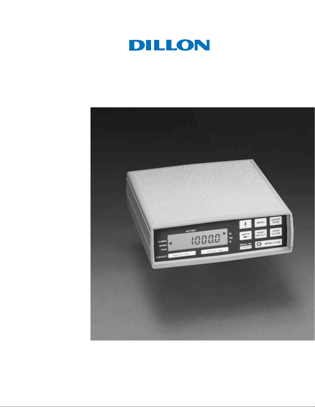
Dillon FI-90 Force Indicator
Users Manual
Page 2

CAUTION
Risk of electrical shock. Do not remove cover. No user service-
able parts inside. Refer servicing to qualified service personnel.
Weigh-Tronix reserves the right to change
specifications at any time.
12/19/03 FI90_U.P65 PN 29527-0011E e2 Printed in USA
2
Page 3

Table of Contents
Table of Contents ................................................................................................. 3
FI-90 Specifications.............................................................................................. 4
Features and Options ........................................................................................... 6
Introduction .......................................................................................................... 7
Keyboard .............................................................................................................. 7
Annunciators ........................................................................................................ 8
Display Messages .............................................................................................. 8
Powering Up......................................................................................................... 9
Getting Around in the Operations Menu ............................................................. 10
Measuring Gross Force ...................................................................................... 11
Measuring Peak Force ....................................................................................... 11
Entering or Viewing an ID Number..................................................................... 12
Entering Data with Arrow Keys .......................................................................... 13
Introduction ........................................................................................... 13
ID Number as an Example ................................................................................. 13
Viewing and Entering Setpoints (Cutoffs) ........................................................... 14
Cutoff Connections ................................................................................ 17
Viewing and Setting Time ................................................................................... 17
Viewing and Setting the Date ............................................................................. 18
Transmitting Data ............................................................................................... 19
Analog Output Option ......................................................................................... 20
Using Test Mode for Indicator Diagnostics ......................................................... 21
Main Displays Viewed in the Test Mode Menu ...................................... 22
Pages are numbered consecutively beginning with the cover page.
3
Page 4

FI-90 Specifications
Display: 7-segment LCD, 6-1/2 digits plus sign, .5 inch high, movable decimal, with
7 annunciators
Display Update Rate: Two times per second
Analog-to-Digital
Conversion Rate: 60 times per second
Resolution: Up to 10,000 divisions standard
Controls: Pushbutton zero; pushbutton peak-hold; pound-, kilogram-, Newton-scroll selection;
PRINT, MENU, and SELECT keys for configuration; ON / OFF switch (optional: used
only on alkaline battery option); BATT / AC switch (optional: used on rechargeable
battery / AC versions)
Peak Detection Rate: 60 times per second
Peak Detection: Threshold 1% of capacity setting
Accuracy : Span: ±5.0 ppm/C Zero: ±.066 uV/C (-10 to 40°C)
Linearity: ±0.005% of capacity, maximum
Repeatability: ±0.005% of capacity, maximum
Hysteresis: 0.005% of capacity, maximum
Power: Std - 117VAC +10/-15% 50/60Hz 5 watt
Opt - 230VAC +10/-15% 50/60Hz 5 watt
Opt - 12VDC +10/-15% 130mA max.
Load Cell Drive Capacity: Up to four 350-ohm load cells. Up to twelve 1000-ohm load cells.
(+5VDC load cell excitation voltage)
Environment: -10 to 40°C (14 to 104°F)
10 to 90% relative humidity
Calibration
and Programming: All calibration and programming is done through the front panel with data stored in
non-volatile memory.
Analog Range: -0.14 to +3.5 mV/V
Scale Capacities: .00001 to 999999, programmable to any number between these limits
Scale Division Sizes: .0001 to 20000, programmable to any division size between these limits
Pushbutton-Zero Range: 0 to ±100% of capacity; programmable in any percentage of indicator capacity;
independent positive and negative limits; unit will not allow zeroing beyond capacity.
Overrange Capacity: The indicator displays force measurements up to and including full-scale capacity
4
Page 5

Automatic Zero Tracking: Window programmable from 0 to 999999 divisions; decimal entries accepted.
Tracking in peak-view mode may be enabled or disabled..
AZT (Auto-Zero
Tracking) Rate: 0.1 division per second; starting delay of 2 seconds
Annunciators: Center of zero, pounds, kilograms, newtons, peak, gross, battery status
Standard Enclosure: ABS grey plastic case with RFI coating
Enclosure Dimensions: 2.65"H x 8.36"W x 9.11"D
RFI Rejection: Operates in the presence of moderate RFI
RS232 / 20mA Output: Data is transmitted when PRINT button is pressed. Host computer may solicit data by
sending an ENQ character. Auto print and broadcast data are also options. Format
programmable.
Baud rate options - 300, 600, 1200, 2400, 4800
Parity bit options - even, odd, logic 1, logic 0
Word length - 8 data bits, including parity
Stop bit options - one or two
Analog Output: Dip-switch selectable, isolated outputs: 1 to 5mA, 4 to 20mA, 10 to 50mA,
0 to +5 volts, 0 to +10 volts
5
Page 6

Features and Options
Standard AC Version
Options: RS232 / 20mA current loop serial I/O with real-time clock
Dual cutoffs with one programmable input
Analog output
230VAC
Panel mount
AC / Lead-Acid Battery Version
Options: RS232 / 20mA current loop serial I/O with real-time clock
Panel Mount
Features: Rechargeable 6V lead-acid battery
Operates on AC or internal battery
Sleep mode to conserve battery power
26-32 hours between recharge (1 load cell, continuous)
14-16 hours between recharge (4 load cells, continuous)
Alkaline Battery Version
Options: RS232 serial I/O with real-time clock
Panel mount
Features: Long battery life - 5 weeks @ 40 hrs / week for one load cell
Sleep mode to conserve battery power
12VDC Version
Options: RS232 / 20mA current loop serial I/O with real-time clock
Panel mount
6
Page 7
Introduction
Keyboard
The FI-90, a full-function force indicator, is available in four versions:
1) the standard AC powered version
2) an AC lead-acid, rechargeable battery version
3) an alkaline battery version
4) a 12 volt DC version
Operations mode provides gross force and peak force readings and allows
viewing and configuration of one or more of these parameters:
ID number
up to two cutoff registers
time
date
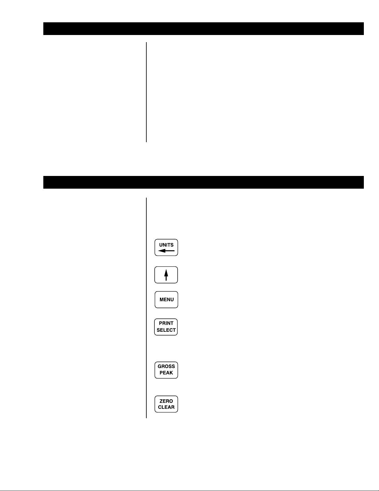
The key board consists of six keys that control all gross and peak force
measuring functions and provide access to configuration and system-test
information. See Figure 1.
A dual function key: UNITS selects the operational unit of
measure; LEFT ARROW enters data.
Enters data.
Selects menu topics.
A dual-function key: PRINT transmits displayed data to a printer,
computer, or programmable controller; SELECT accepts dis-
played data in configuration and helps you move around in the
configuration hierarchy.
A dual-function key toggles between gross mode and peak-view
mode and displays gross force or peak force.
A dual-function key: In gross mode, ZERO established a zero
reference; In peak-view mode, CLEAR clears the retained peak
value and displays the current gross load input.
7
Page 8

ON
FI-90 Front-Panel Keyboard, Annunciators, and Display
Annunciators
Figure 1
Gross Illuminates when the indicator is in gross mode.
Peak Illuminates when the indicator is in peak-view mode.
lb, kg, N Illuminates to show the active unit of measure.
Battery Illuminates when the battery voltage is low. "D" cells should be
replaced or a lead acid battery recharged.
C/Zero Illuminates when the indicator is within ±1/4 division of zero or the
force at which the indicator was zeroed.
Display Messages
- - - - - - -
[
[
- - - - - - -
[8888888] Appears briefly at the time of power on. The indicator is
[ Loc'd ] The A-D converter is locked up. Applied force is too high
[ASLEEP] The indicator has gone to sleep to conserve on battery
] The indicator is in a state of over capacity.
] The indicator is in a state of under capacity.
being initialized.
or too low.
power. Make it operational again by pressing any key.
8
Page 9

Powering Up
The method of powering up depends on the type of power supply your
indicator uses. Look at the back panel of your indicator and the four back
panel illustrations below and identify the one that matches your indicator.
Then follow the appropriate power-up instructions on the next page.
Figure 2
Back Panel of Standard AC-Powered Version
Figure 3:
Back Panel of AC / Lead-Acid, Rechargeable-Battery Version
Figure 4
Back Panel of Alkaline-Battery Version
Figure 5
Back Panel of Twelve-Volt-DC Version
9
Page 10

For the standard AC version (See Figure 2): Plug the power cord into the
back of the indicator and connect the cord with an external AC power source.
The FI-90 indicator powers up
in the same mode it was in
when power was removed.
For the AC / lead-acid battery version (See Figure 3): The power switch
controls your choice of AC power or internal lead-acid battery power. To use
external AC power, depress the bottom portion of the power switch, and plug
the power cord from an AC power source into the AC receptacle. To use the
internal lead-acid battery, depress the top portion of the power switch.
For the alkaline battery version (See Figure 4): Press the power switch to
the ON position (lower portion depressed).
For the 12-volt DC version (See Figure 5: Press the power switch to the ON
position (lower portion depressed).
Getting Around in the Operations Menu
Your unit is configured to display gross force or peak force. It may also be
configured to display one or more of the following functions: ID number, one or
two cutoff registers, time, and date. This manual assumes the unit is config-
ured to allow full access to all functions. The following flowchart and instruction procedure explains how to move around in and use the operations menu.
10
Figure 6
Operations Menu
Press MENU to à
Press SELECT to go á or â
Press and hold MENU to go ß
Press SELECT to select new choice and go á
Page 11

Measuring Gross Force
1. Power up the indicator. . . The FI-90 powers up in the same
2. Access the gross mode. If the
3. Zero the FI-90 by pressing
4. Select unit of measure by
mode it was in when power was
removed.
gross annunciator is not
illuminated, press
GROSS / PEAK once. . . The gross annunciator illuminates
(See Figure 2).
ZERO / CLEAR (Any stable
applied force up to full-rated
capacity may be zeroed off). . . 0 is displayed. Any small changes
in force are zero tracked automatically and the displayed zero is
maintained.
pressing UNITS. . . The units annunciator indicates your
selected unit of measure.
5. Apply force . . . The applied gross force is displayed.
Measuring Peak Force
This procedure allows the FI-90 to monitor a varying force and hold the peak
value.
1. With the indicator powered up in
2. Press GROSS / PEAK to access
3. Remove force, or await removal of
In peak load applications,
removal of force occurs when
maximum tension or compression strength of the material or
product is met.
the gross mode, zero by pressing
ZER0 / CLEAR and apply force. . . Gross displayed value increases to
reflect increasing live force.
peak-view mode. . . The peak annunciator comes on.
Displayed is the incrementing peak
value. It reflects the live gross force
continuing to increase.
force. . . The force now displayed is the
retained peak value. Retained peak
is measured precisely at the maximum load sensed by the indicator
before force is reduced. Retained
peak value stays displayed while the
live gross force drops.
11
Page 12

4. View and, if necessary, record the
retained peak value. Press
PRINT / SELECT to transmit data
to a peripheral deviceprinter,
chart recorder, or computer or
other programmable controllerif
interfaced via the RS232 or 20mA
option.
5. Clear the last retained peak value
by pressing ZERO / CLEAR, and
re-apply force. . . The retained peak value is released
and 0 is momentarily displayed. The
display increments in the peak-view
mode, reflecting increasing live gross
force.
6. You may view increasing force in
the gross mode by pressing
GROSS / PEAK. . . The gross annunciator comes on and
gross force is displayed. Important:
The next peak captured (see step 8)
will not be displayed with the FI-90
toggled to gross mode, but the peak
will continue to be tracked and can
only be viewed in the peak-view
mode.
7. As desired, you may again view
your last retained peak (displayed
by step 4) by toggling
GROSS/PEAK. This key allows
you to toggle between peak-view
mode and gross mode.
8. Repeat steps 3, 4, and 5 for each
peak force measurement
needed. . . The indicator will capture the new
Entering or Viewing an ID Number
You may enter an identification number of up to seven digits.
1. While in gross weighing mode,
press MENU repeatedly until. . . ID. is displayed.
retained peak when force goes above
the last retained peak, even if it is
not displayed, and you can toggle to
the peak-view mode to view it as
desired.
12
2. Press PRINT / SELECT. . . The current identification number is
displayed.
Page 13

3. You now have two choices, A or B:
A. Accept the displayed ID by
pressing either GROSS /
PEAK or PRINT / SELECT. . . GROSS / PEAK takes you directly
Or
B. Enter a new ID of up to seven
digits. Use the data entry
procedure shown in the
section, Entering Data with
Arrow Keys. Then press
PRINT / SELECT. . . The new ID number is accepted and
Entering Data with Arrow Keys
out to the gross mode. PRINT /
SELECT displays ID.
ID is displayed.
Introduction
ID Number as an
Example
If at any time you enter an
incorrect character, press
ZERO / CLEAR to backspace
and delete the wrong character,
then re-key.
The arrow keys are used to enter data for the ID number, cutoff numbers,
time, and date. Refer to this section whenever the manual instructs you to
enter data for one of those parameters.
Entering data is all done through a single edit character position on the
display. The UP ARROW key increments the digit displayed in the edit-
character position up to the value needed, and the LEFT ARROW key moves
the configured digits to the left, out of the way, and brings up a new zero digit
in the edit-character position. The FI-90 allows you to enter up to seven
character positions of data.
To teach the procedure, we'll show you how to enter the three-digit ID number, 603. The same keying principles generically apply to your entry of ID,
cutoffs, time, and date.
1. Starting from a display of the
current identification number (the
outcome of step 2 under Entering
or Viewing an ID Number), press
the UP ARROW key. . . First, a zero is displayed
in the edit character
position, indicated here by
an arrow. Only in the edit-
character position can
you edit the numeric value of a digit
upward or downward.
13
Page 14

2. Start with the left-most digit (in
our example, a 6 ). Pressing UP
ARROW one depression for each
whole number, increment the
displayed number up to the
desired value. . .
3. Then press LEFT ARROW to
bump the 6 a single space to the
left and display a 0 in the
edit-character position. . .
4. The 0 in the edit-character position
is acceptable for our example's
second digit, so no depressions of
UP ARROW are required for it.
Instead, press LEFT ARROW
again to bump the 60 a single space
to the left and again display a 0 in
the edit-character position. . .
A data field of more than the
three digits entered in our
example ID number would
require one additional combination of LEFT ARROW and UP
ARROW keyings for each
additional digit.
5. Press UP ARROW, as necessary,
to increment the edit character to
the desired value, a 3 in our 603
example. . . Entry of ID #603 is complete.
14
Page 15

Viewing and Entering Setpoints (Cutoffs)
A setpoint cutoff is a force-load value at which an internal electrical connection is broken, causing an external relay to de-energize. Additional relay
configurations can turn on or shut off another electrical device.
You may configure the FI-90 to accept either one of two types of cutoff: (1) a
gross-based setpoint or (2) an increment-based setpoint. A gross-based
setpoint is called, simply, a setpoint. With this type of setpoint, activation of
a cutoff is signaled by a specified gross applied force. You specify, through
the front-panel keypad, the gross force-load setpoint that will activate each
cutoff. For example, suppose your first cutoff requires 100 pounds of force,
and your second cutoff requires 200 pounds of force; you would set the first
setpoint at 100 pounds of force and the second setpoint at 300 pounds of
force, because those values will represent gross force load when the cutoffs
activate.
With the increment-based setpoint, activation of a cutoff is signaled by a
specified amount of net force. You tell the indicator the net amount of force
required to activate each of the cutoffs. Suppose your first cutoff requires 100
pounds of force, and your second cutoff requires 100 pounds of force; you
would enter 100 for setpoint #0 and 100 for setpoint #1.
You can view the type of setpoint that has been configured in your indicator
by looking at the cutoff display in the operations menu. A decimal point
following the word cutoff indicates configuration of gross-based setpoints. If
no decimal point appears after cutoff, the FI-90 is configured for incrementbased setpoints.
The two setpoint registers are
numbered #0 and #1.
1. Starting from either gross mode or
peak-view mode, press MENU
twice to access. . . CutOFF.0 The decimal after CutOFF
says this is a gross-based setpoint.
Then press PRINT / SELECT. . . nn.n is displayed. The n 's represent
the current value in register 0 .
15
Page 16

2. Enter a new setpoint value in
register #0, using the procedure
presented in the section, Entering
Data with Arrow Keys. Before you
enter any numeric values, specify
a negative setpoint, if appropriate
for your application. To display a
negative sign, "-", use
UP ARROW to scroll through all
digits and characters until the
sign is displayed. Then press
LEFT ARROW to place a new
edit character in the edit position.
To display a decimal point in your
setpoint, scroll similarly through
all digits until the decimal is
displayed. Use the arrow keys to
enter all digits of the new
setpoint. When the correct
setpoint is displayed, press
PRINT / SELECT to accept the
value and redisplay. . . CutOFF.0
then press MENU to move to the
next register (register #1). . . CutOFF.1 is displayed (if the
second setpoint has been configured;
if not, you now see the time display).
The 1 now displayed stands for
setpoint register #1.
3. Press PRINT / SELECT. . . nn.n is the current value in register
#1.
4. Enter a new setpoint in cutoff
register #1 (See #2 and Entering
Data with Arrow Keys).
5. Press PRINT / SELECT to
accept the value and redisplay. . . CutOFF.1
then press MENU to see the
clock or GROSS / PEAK to go
back to gross or peak-view mode.
16
Page 17

Cutoff Connections
The cutoff connector located on the bottom of the indicator is a nine-pin
female connector. Figure 7 shows the pin assignments.
Signal Name Pin Number
+12v (on 12v units) #9
+ Relay voltage #6
Cutoff 0 #1
Cutoff 1 #2
Logic ground #5
Shield #7
Remote input #4
Figure 7
Cutoff Connection Pin Assignments
Viewing and Setting Time
1. From gross or peak-view mode,
press MENU repeatedly until
Hour is displayed, then press
PRINT / SELECT. . . A 12-hour clock displays time in
2. Set the clock by entering data in
the desired format, as shown in
the outcome to step 1 (12- or
24-hour time), using the data
entry procedure documented
under Entering Data with Arrow
If you enter an incorrect
character, press ZERO /
CLEAR to backspace and
delete the wrong character,
then rekey.
Keys. Start by changing AM to
PM or vice versa, if necessary:
use UP ARROW to scroll through
numbers to this display, . .- A or . .- P
then press LEFT ARROW to
change A to P or P to A. . . . 0 P or . 0 A. Zero is now in the
hours and minutes, plus A for
A.M. or P for P.M: 09 40 A . A 24-
hour clock displays hours, minutes, and seconds: 09 40 38.
edit-character position, ready for
the leftmost digit of the time data
string to be entered.
17
Page 18

3. After the clock is set, you may
press PRINT / SELECT to start
the clock and return to operations
mode menu,. . . Hour is displayed and the clock
or
press GROSS / PEAK to return
to gross or peak-view mode. . . The clock starts at the new time
Viewing and Setting the Date
1. From gross or peak-view mode,
press MENU repeatedly until
dAY is displayed, then press
PRINT / SELECT. . . Depending on the configuration of
If you enter an incorrect digit,
press ZERO / CLEAR key to
clear the display one digit at a
time.
2. To change the date, start by
pressing UP ARROW to bring a
0 into the edit-character position,
and continue using the procedure
explained in the section, Entering
Data with Arrow Keys. Use the
same date format that you saw
when you displayed the date in
step 1.
begins.
setting.
your indicator you will see the date
displayed in one of three ways:
day-month-year31.12.92
month-day-year12.31.92
year-month-day92.12.31
18
3. Press PRINT / SELECT to return
to the operations mode menu,. . . The date is accepted and dAY is
displayed.
or
press GROSS / PEAK to return
to gross or peak-view mode. . . The date is accepted and the display
returns to gross or peak-view mode.
Page 19

Transmitting Data
Your indicator requires an RS-232 / 20mA output for data transmission. The
RS-232 / 20mA connector is located on the bottom of the indicator and is a 9pin male connector. Connect a printer following the pin assignments listed in
Figure 8.
RS-232
Pin
Signal Name Number
Transmit to printer #3
Receive from printer #2
CTS (BUSY) from printer #8
DTR (READY) to printer #4
Logic ground #5
Shield #9
Signal Name Pin Number
TTY REC + #8
TTY XMT - #3
TTY REC - #2
TTY XMT + #7
Logic ground #5
Shield #9
20mA
Figure 8
RS-232 Connector Pin Assignments
If your indicator is configured to allow
printing, from the gross or peak-view
mode, press PRINT / SELECT. . . Data is transmitted and the data
configured to be printed will be output
to the printer. See Figure 9 for a
sample printout.
Figure 9
Sample FI-90 Printout
The default settings for serial output are:
Busy Disabled
Baud 1200
Parity Clear
Stops 1
19
Page 20

Analog Output Option
An optional, isolated analog output provides dip-switch selectable output: 15mA, 4-20mA, 10-50mA, 0-5VDC, 0-10VDC. The analog output can be used
with programmable controllers, chart recorders, etc. It uses a nine-pin female
connector as shown in Figure 10.
Signal Name Pin Number
Current return #1
Voltage out #4
Voltage return #5
Current out #6
Chassis ground #9
Figure 10
Analog Output Pin Assignments
20
Page 21

Using Test Mode for Indicator Diagnostics
Test mode allows you to test various functions of the FI-90. A flowchart of the
test mode menu is shown in Figure 11, followed by instructions for getting
around in the test mode and executing tests.
Figure 11
Flowchart of the Test Mode Menu
1. Enter the test mode from gross or peak-view mode by pressing and
holding MENU until tESt is displayed. SEAL or unSEAL is displayed
briefly while you hold the key.
2. Move to the right through the menu selections by briefly pressing MENU.
Move to the left through the menu selections by pressing MENU for one
second. Scroll continuously to the left by pressing and holding MENU.
3. Move down a level in the test mode hierarchy by pressing PRINT /
SELECT. Move up a level in the hierarchy: from any display in the
hierarchy, by pressing and holding PRINT / SELECT for approximately
1.5 seconds; or from the End display, by pressing PRINT / SELECT.
4. Press MENU to toggle between the options under any test parameter,
such as the ready and busy options under the serial test parameter.
5. Press GROSS / PEAK to return to gross or peak-view mode at any time.
Descriptions and instructions follow for the tests and parameters you see in
the test mode flowchart.
21
Page 22

Main Displays Viewed
in the Test Mode Menu
VERSION version - Under version are the Weigh-Tronix part number for
the FI-90 force indicator, and the revision number for
the software found in your unit. Weigh-Tronix part
numbers are divided into two parts: a five-digit prefix
and a four-digit dash number.
dISPLAY display - From this display: dISPLAY, press PRINT / SE-
LECT and the top row of annunciators turns on.
Press PRINT / SELECT again and a dynamic test is
run. Press MENU to stop the dynamic test or
consecutively press MENU to step through the
display test routine. Press PRINT / SELECT when
the dynamic test is active to return the display to
dISPLAY.
buttonS buttons - With bUttOnS displayed, press PRINT / SELECT
and an underscore will appear on the screen. Press
any key except MENU to check for proper key
functioning. After testing the keys, press MENU to
return the display to bUttonS.
OutPutS outputs - These tests allow you to turn the cutoffs on and off
automatically in sequence, under CYCLE, or individually, under CUTOFF 1 and CUTOFF 2. When
you exit the outputs test, the cutoffs revert to their
proper condition according to the applied gross force.
input input - This test tells you how the remote control input is
configured. It may be off, or it may be configured as
a remote PRINT key control, a remote GROSS /
PEAK key control, or a remote ZERO / CLEAR key
control. With input displayed, press PRINT /
SELECT and an underscore will appear. Activate the
external remote switch, and the display will print the
name of the key to which the remote input is dedicated, verifying proper functioning of the connection.
VoltAgE voltage - The input power voltage is displayed in tenths of a
volt. In the battery versions, the BATTERY annunciator comes on when the voltage reaches approximately 5.4 volts.
A to d A to D - Displays the analog-to-digital counts. The span is
normally 20,000 counts per millivolt per volt. With a
calibrator at zero millivolts per volt, the displayed
value should be between -200 and +200.
SEriAL serial - Tells you if the serial output is ready or busy. A
jumper connecting pins 4 and 8 of the serial port will
cause READY to be displayed.
22
Page 23

23
Page 24

Dillon
A division of Weigh-Tronix Inc.
1000 Armstrong Dr.
Fairmont, MN 56031 USA
Telephone: 507-238-4461
Facsimile: 507-238-8258
e-mail: dillon@weigh-tronix.com
www.dillon-force.com
Force Measurement Products & Systems
 Loading...