

Page 1

FI-80 LCD / FI-80 LED
Indicators
User’s Manual
Contents subject to change without notice.
Dillon division of Avery Weigh-Tronix
1000 Armstrong Drive
Fairmont, MN 56031 USA
Sales (507) 238-8796
Service (507) 238-4461
Register your Dillon product, get manuals and see other quality force measurement products at:
www.dillonforce.com
Page 2

TABLE OF CONTENTS
Page
Introduction to the FI-80 Series Indicator........................................................................................ 3
Installation .......................................................................................................................................... 3
Operation ............................................................................................................................................ 4
S etup / Configuration......................................................................................................................... 8
Appendix A: Specifications.............................................................................................................. A-1
Appendix B: Serial Port Information................................................................................................ B-1
Appendix C: Displayed Error Codes ............................................................................................... C-1
Page 3

INTRODUCTION TO THE FI-80 SERIES DIGITAL INDICATORS
The FI-80 Series Digital Indicator is a general purpose, industrial grade force indicator. Two models are
available with different display types and power supply.
MODEL DISPLAY TYPE POWER SOURCE
FI-80 LED Light Emitting Diode (LED) 110/220 VAC, 50/60 Hz
FI-80 LCD Liquid Crystal Display (LCD) Internal 6V battery with 12 VDC 800 ma charger
The LCD model contains a 6V rechargeable battery as the primary power source. The external power
supply with these units functions as a charger for the rechargeable battery and may also be used as the
main power supply.
The FI-80 is commonly outfitted at the factory with a load cell, hardware accessories and serial cable to fit
your specific requirements. It is calibrated and is ready for installation into your application. Alternatively,
your reselling distributor may have equipped this indicator for use with a particular load cell and calibrated
the system together. Confirm that a certificate of calibration is on hand for the FI-80 Indicator and load
cell combination. Prior to installation, you should view and record the calibration values in your FI-80.
This is found at the end of the SETUP section.
Please read this manual carefully and completely prior to using the indicator. Store the manual in a safe
and convenient place so it will be available if you have questions concerning the operation of your
system.
INSTALLATION
INSTALLING THE LOAD CELL
Install the load cell according to your specific equipment and application. Set-up will vary
between systems. Some things to keep in mind for best measurement performance
1. Insert the load cell fully in-line with the tensile or compressive force axis. Off center
loading may result in measurement errors.
2. Allow for movement and relief of undesired loads.
a. Compression load cells typically have one load cell end fixed in all directions
and the other end uses a load button or ball bearing to apply a single point load
that is free of undesired bending and torque loads.
b. Tension load cells are often not rigidly affixed to surfaces. In this arrangement it
becomes self aligning under load. Two convex surfaces contacting each other
offers good immunity from undesired bending loads and a limited range of
torque loads. An example is a lifting eye suspended from a shackle bolt.
CONNECTING THE POWER SUPPLY
The FI-80 LED indicator includes a hardwired AC line cord. Simply plug the unit into a
standard wall outlet.
The FI-80 LCD indicators ship with the rechargeable battery pre-installed. The external
power supply (included) can also be used to power the indicator. The adapter acts as the
battery charger and the FI-80 LCD must use a 12 VDC, 800 mA adapter.
1. Simply plug the AC adapter into the indicator’s DC Power Jack first, and then plug into a
standard wall outlet. Make sure that the AC voltage appearing at the wall outlet
3
Page 4
matches the input voltage marked on the AC adapter.
OPERATION
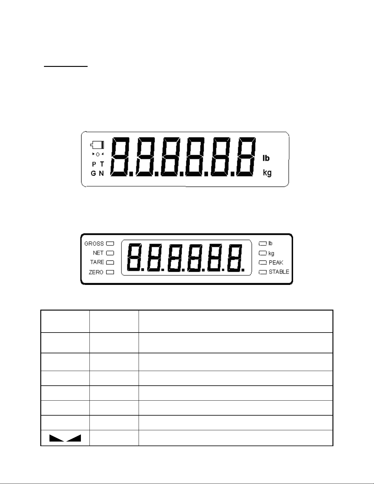
D ISPLAY
The two display types are 6 digit LCD (Liquid Crystal Display) and 6-digit LED (Light Emitting Diode)
display. Typically, LCD’s are used for outdoor applications while LED’s are used indoors where
brightness is needed. Table 7-1 summarizes both types of display annunciators.
LIQUID CRYSTAL DISPLAY (LCD)
LIGHT EMITTING DIODE (LED) DISPLAY
FI-80 LCD Detail
LCD
Annunciator
LED
Annunciator
0 ZERO
N NET
G GROSS
P PEAK
T TARE
lb, kg lb, kg
STABLE
TABLE 7-1: FI-80 Series Annunciator Definitions
FI-80 LED Display Detail
MEANING
Better known as the “Center of Zero” annunciator, this light is active
whenever the displayed load is within ± 0.25 divisions of true zero.
The FI-80 is displaying net load.
The FI-80 is displaying gross load.
The FI-80 is displaying peak load.
A tare load has been saved.
The active unit of measure.
Appears whenever the load is stable.
Page 5
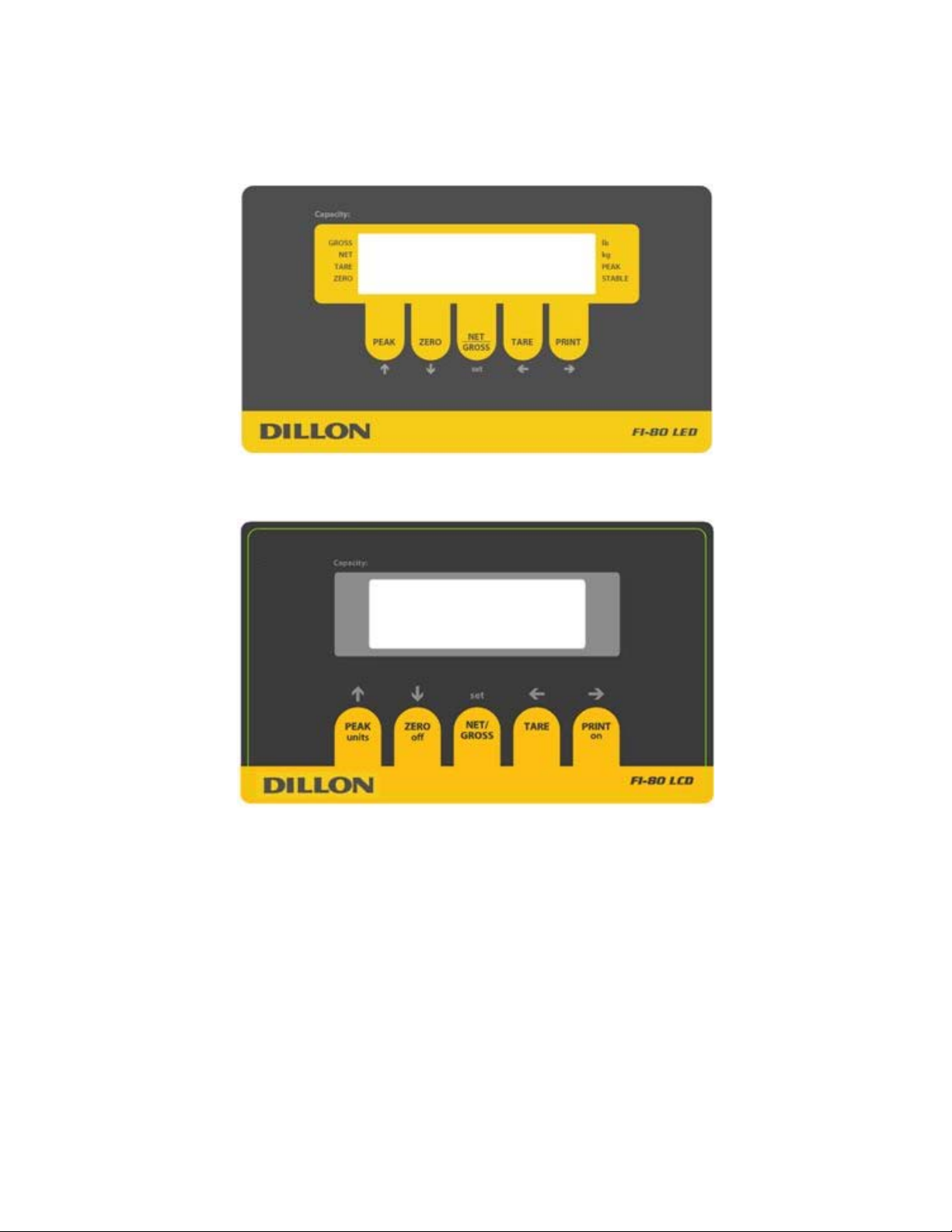
FRONT PANELS
FUNCTION KEYS
PEAK – Toggles the indicator between normal live display mode and peak hold mode (Setup
ZERO - Sets the FI-80 to display “0” provided the following conditions are met:
1. The FI-80 is displaying Gross load.
2. The displayed load is within the zero reset range (F4 in setup).
3. The load is not in motion (F5 in setup).
4 . The FI-80 is not in overload (see Appendix D for error codes).
LED version front panel
LCD version front panel
5 must be set at “0” on the LCD version). A
NET/GROSS - Toggles the indicator between Gross load and Net load only if a Tare has
een established. b
TARE - Establishes a Tare provided the following conditions are met:
1. The reading is not at or below Gross zero.
2. The load is not in motion.
Page 6

3. The FI-80 is not in overload (see Appendix D for error codes).
PRINT - Sends display reading through the serial port when the following conditions are met:
1. The display is not changing.
2. The FI-80 is not in overload (see Appendix D for error codes).
See Appendix B for connection and print format details.
UNITS – (LCD model only) Toggles the indicator between lb and kg if enabled (A5 at “1”)
and peak hold is not configured (A11 at “0”). In any other conditions, the FI-80 LCD will
isplay only the default unit of measure. d
O FF – (LCD model only) When held for five seconds, shuts the unit off.
ON – (LCD model only) Turns the FI-80 on.
GENERAL OPERATION
DISPLAYING LOAD
TARING AN ITEM
PEAK HOLD
1. Select the desired unit by pressing the lb/kg key until that unit is indicated on the display.
2. Press the ZERO key to obtain a load reading of zero when necessary,.
3. Place the object to be weighed on the scale’s platter and allow the load indication to
stabilize. If the item load exceeds the load cell capacity, it displays “SSSSSS”.
4. Read the load shown on the display.
To weigh an item in a container, the weight of that container must first be subtracted from
the overall weight to obtain an accurate weight reading. This is known as taring.
1. Select the desired weighing unit by pressing the lb/kg key until that unit is indicated on
the display.
2. If necessary, press the ZERO key to obtain a weight reading of zero.
3. Place the empty container on the scale’s platter and allow the weight indication to
stabilize.
4. Press the TARE key. The display shows zero weight and turns the NET annunciator on.
5. Place the material to be weighed in the container and allow the weight indication to
stabilize.
6. Read the weight shown on the display.
7. You may toggle between the gross weight and the net weight by pressing the
NET/GROSS key.
Overview
1. The indicator has two modes of operation: NORMAL OPERATING mode and PEAK-HOLD mode.
2. Press the PEAK key to toggle the indicator back and forth between NORMAL OPERATING mode
and PEAK-HOLD mode. (Peak Hold mode must be enabled in the FI-80 LCD – see
Normal Operating Mode
Page 7

1. All keys perform as described in the manual while in this mode.
Peak-Hold Operation
In Peak-Hold mode, the display updates as the load increases, but not as the load decreases.
LCD version
1. Press PEAK to enter peak hold mode. The “P” annunciator appears on the left side of the display
when PEAK HOLD mode is engaged and the value on screen is the peak value.
2. The ZERO key clears the previously stored peak value and zeroes the indicator. Hint: To clear
the peak without rezeroing, press the PEAK key twice.
3. The PRINT key operates as it does in the NORMAL OPERATING mode.
LED version
1. Press PEAK to enter peak hold mode. The PEAK LED is lit when PEAK HOLD mode is engaged
and the value on screen is the peak value.
2. The ZERO key clears the previously stored peak value but does not zero the indicator. Hint: If
rezero is required, enter Live display mode, zero and return to Peak display
3. The NET/GROSS and TARE keys are locked out function in this mode.
Page 8

SETUP
SETUP OVERVIEW
The indicator contains two main setup menus:
1. The “F” menu items configure the indicator to the attached load cell and is known as
“Configuration” settings. Most of these are entered by a qualified instrumentation
technician.
2. The “A” menu items configure the serial communication port and general user options.
In setup mode the front panel keys become directional navigators to move around in the menus and to save
the selections.
ENTERING THE SETUP MENU
1. Power off the indicator.
2. Locate the slide switch on the rear cover and move it to the right.
NOTE: A metal plate held on by two drilled-head screws may conceal the slide switch.
The back cover may have a seal to keep unauthozed personnel from making changes
to the indicator.
3. Power on the indicator. The indicator shows ” F 1” to indicate that you are in Setup
Menu mode.
NAVIGATING IN THE SETUP MENU
Use the directional keys shown in Figure 3-1 to move around in the Setup Menu Chart
shown in Figure 3-2 on the following page.
1. Press and keys to move left and right to advance to the next or previous “F/A”
setup heading.
2. Press the key once. The current saved setting is shown.
3. Press and keys to scroll through selections for the current setup heading.
4. press the Set key to save the new selection. Press the key to escape without saving
and return to the current heading,.
5. Repeat Steps 1 through 4 until the desired Setup & Configuration changes are made.
SET
Figure 3-1: Setup Menu Key Assignments
8
Page 9

EXITING THE SETUP MENU
1. Power off the indicator.
2. Move the slide switch on the rear cover back to the left.
3. Power on the indicator. The display will go through a digit check, then settle into Normal
Operating mode. All front panel keys will now return to their normal mode of operation.
SETUP MENU DESCRIPTIONS
List and detailed descriptions of the items within the setup screens. Factory-s et defaults are s hown in
bold with a checkmark (√).
Note: Most “F” menu items configure the indicator to the attached load cell and are entered by a
qualified instrumentation technician. These parameters do not appear in this manual. Do not
change these parameters, or the indicator may not function properly or may report highly
inaccurate readings!
NAME/CODE DESCRIPTION CODE/VALUE
F1
F2
F3
F4
Zero Range
F5
Motion Band
This item is for configuration by a qualified load cell indicator
technician. Do not change this value or the instrument readings may
be in error.
This item is for configuration by a qualified load cell indicator
technician. Do not alter this value or the instrument readings may be
in error.
This item is for configuration by a qualified load cell indicator
technician. Do not alter this value or the instrument may respond
unpredictably.
Selects the range within which the scale may be zeroed. Note that the
indicator must be in standstill to zero the scale.
Defines ‘motion’ in number of divisions of change between the
present display update and the previous display. If motion has been
detected within the prior two seconds, the Print and Zero commands
are disabled.
If a stable reading is not needed for printing or zeroing in your
application, set this value at its highest number.
500 1,000
1,500 2,000
2,500 3,000
4,000 5,000√
6,000 8,000
10,000 12,000
20,000 30,000
40,000 50,000
25 50
75√ 100
150 200
0d
0.5d√
1d
3d
5d
100%√
1.9%
FI-80 LCD extras:
2%
20%
1d√
3d
5d
10d
FI-80 LCD extras:
0.25d 15d
20d 30d
40d 50d
Page 10

F6
Digital Filter
Averages load readings to produce higher stability. The higher the
filter setting, the greater the stability but the slower the indicator’s
response time. Choose 8 unless a very fast response is needed.
1 2
4 8√
FI-80 LCD extras
16 32
64 128
:
F7
F8
F9
F10
F12 (LCD
version only
F16
F17
This item is for configuration by a qualified load cell indicator
technician. Do not alter this value or the instrument may respond
unpredictably.
This item is for configuration by a qualified load cell indicator
technician. Do not alter this value or the instrument readings may be
in error.
This item is for configuration by a qualified load cell indicator
technician. Do not alter this value or the instrument readings may be
in error.
This item is for configuration by a qualified load cell indicator
technician. Do not alter this value or the instrument readings may be
in error.
Not presently used. Keep parameter on 10. 5
This item is for configuration by a qualified load cell indicator
technician. Do not alter this value or the instrument readings may be
in error.
This item is for configuration by a qualified load cell indicator
technician. Do not alter this value or the instrument readings may be
in error.
FS
FS + 2%√
FS + 1d
FS + 9d
1√
2
1√
2
5
0√ 0.0
0.00 0.000
0.0000 00
10√
20
50
75
100
Do not press
key
Do not press
key
F18
View Calibration
F19
F20
F21
Factory Reset
F23 (LED
version only
F24 (LED
version only)
Shows both the zero and span calibration value.
This item is for configuration by a qualified load cell indicator
technician. Do not alter this value or the instrument readings may be
in error.
This item is for configuration by a qualified load cell indicator
technician. Do not alter this value or the instrument readings may be
in error.
This sub-menu will reset all parameters in the “F” and “A” menus to
the default settings. USE WITH CAUTION!
Not presently used. Arbitrary value
Not presently used. Keep parameter on 0.
Press
key to
begin sequence
Do not press
key
Do not press
key
Press the
twice to execute.
0√
1
key
Page 11

A1
Baud Rate
Baud rate for data transmission through the serial port. 1200 2400
4800 9600√
19200
A2
Data Bits and
Parity
A3
Mode of Serial
Transmission
A4
Display Check
A5
Disable the
UNITS key
A6
Serial Port
Mode
A7
ID No. Enable
Number of data bits and parity of serial transmission.
"8n" = 8 data bits with no parity bit and one stop bit
"7O" = 7 data bits with odd parity bit and one stop bit
"7E" = 7 data bits with even parity bit and one stop bit
"7n" = 7 data bits with no parity bit and two stop bits
Data send mode:
"C" = Continuous mode; send data continuously
"d" = Demand mode; send data when a PRINT command is issued
from the printer, computer, or indicator.
Illuminates all digit segments, decimal points, and LCD annunciators
in a test sequence.
Disables the UNITS key so the operator does not inadvertently
change the displayed units.
"0" = Disable the lb/kg key "1" = Enable the lb/kg key
This function is only relevant on the FI-80 LCD when A11 peak hold
functionality is disabled.
RS-232 serial port mode:
"0" = Full Duplex Mode
"1" = Print Ticket Mode
Refer to Appendix B for more information.
Include ID number in the Print Ticket mode. Valid only when A6 is set
to “1”.
"0" = Disable the ID No. "1" = Enable the ID No.
8n√
7O
7E
7n
C
d√
Press
key to
begin sequence
0
1√
0
1√
0√
1
A8
ID No. Entry
A9
No. of Line
Feeds
LED version only (see below for LCD version)
A10
(LED version)
Handshaking
Enable
A11
(LED version)
LCD version only
A10
(LCD version)
Auto Power Off
Period
Change ID Number printed on ticket. Valid only when A6 is set to “1”.
Number of line feeds printed on ticket. Valid only when A6 is set to
“1”.
Enables hardware handshaking for Print Ticket Mode. Valid only
when A6 is set to “1”.
"0" = Disable Handshaking "1" = Enable Handshaking
Not presently used. Keep parameter on 0.
Selects the auto off time period in minutes:
“Off” = Disabled (Always ON)
Auto-off occurs when display does not change or buttons are not
pressed within the timescale.
0 - 999999
123456√
0 – 99
8√
0√
1
0√
1
Off
1, 2, 3, 5√, 8,
10, 15, 20, 30
Page 12

A11
(LCD version)
Peak-Hold
Mode
Enables “Peak Hold” mode. The display will only increment upward
and the peak reading is retained. Press PEAK key to enter and exit
the mode once active.
“0” = Peak Hold disabled, “3” = Peak Hold enabled
Note: UNITS are locked in default when A11 is enabled.
0√
3
A12
(LCD version)
Handshaking
A13
(LCD version)
Enables hardware handshaking for Print Ticket Mode. Valid only
when A6 is set to “1”.
"0" = Disable Handshaking "1" = Enable Handshaking
Not presently used. Keep parameter on 0.
USER MENU PROCEDURES
This section provides instructions for some parameters.
ID Number Entry (A8)
1. Scroll to "A 8" and press the key.
2. The display will momentarily show "ID NO", followed by a value with one flashing
digit. This value will be the current ID number value.
3. Use the four directional keys to adjust the displayed value to the actual ID Number
value. Increase and decrease the flashing digit by pressing or . Decrease
the flashing digit by pressing the ZERO key. The and keys will change the
position of the flashing digit.
4. After entering the exact value, press the Set key to save the ID Number value. The
display will show "SET" momentarily and revert back to A8.
0√
1
0√
1
LF (Line Feeds) Number Entry (A9)
1. Scroll to "A 9" and press the key.
2. The display will momentarily show "LF", followed by the current line feeds value.
3. Use the four directional keys to adjust the displayed value to the actual ID Number
value. Increase and decrease the flashing digit by pressing or . Decrease
the flashing digit by pressing the ZERO key. The and keys will change the
position of the flashing digit.
4. After setting the exact value, press the Set key to save the line feeds value. The
display will show "SET" momentarily and revert back to A9.
Page 13

VIEW CALIBRATION VALUES (F18)
1. While in the Setup mode, scroll to "F 18", then scroll down once using the key to enter View
Calibration menu.
2. The display will momentarily show "CAL 0" followed by a value. This value is the zero
calibration value and should be recorded in the table below. Press any key to continue.
3. The display will momentarily show "CAL 1" followed by another value. This value is the span
calibration value and should also be recorded in the table below. Press any key to return to
upper level (F18).
SERIAL NUMBERS
*
ZERO CALIBRATION
SPAN CALIBRATION VALUE
VALUE
FI-80:
CAL 0: CAL 1:
Load cell 1:
List any additional cells connected:
Table 6-1: Calibration Value Table
* Calibration is only valid for exact system calibrated. If any items are changed or removed, the
system must be recalibrated together or significant errors may result.
* Record the new values after each recalibration.
Page 14

APPENDIX A: SPECIFICATIONS
ANALOG SPECIFICATIONS
Excitation Voltage +10 VDC (LED), +5 VDC (LCD)
No load input 0.00 mV/V
Load cell output level up to + 3 mV/V
Sensitivity
Internal Resolution Approximately 150,000 counts
Display Resolution 50,000 display division max
Measurement Rate 10 Measurements /sec, nominal
System Linearity Within 0.02% of FS
Calibration Method Software Calibration, with long term storage in EEPROM
Maximum load cell support
0.4 μV / grad
4 x 350Ω load cells
OPERATOR INTERFACE
Display – LED Indicators 0.56" (14 mm) 7-segment, LED, 6 Digit
Display – LCD Indicators 0.8" (20 mm) 7-segment, Liquid Crystal, 6 Digit
Additional Symbols Net, Gross, Stable, Tare, lb, kg, Zero, Peak
Keyboard 5-key flat membrane panel
POWER
Rechargeable Battery – FI-80 LCD 6 VDC, 3.0 Ah lead acid with 12 VDC,
800mA charger
DC Power Consumption - FI-80 LCD
DC Power Consumption - FI-80 LED
55mA + 15mA/350Ω Load Cell
200mA + 30mA/350Ω Load Cell
ENVIRONMENTAL
Operating Temperature
Storage Temperature
14° to +104° F (-10° to +40° C)
-13° to +158° F (-25° to +70° C)
MECHANICAL
Overall Dimensions (L x W x H) 10.4" x 3.1" x 7.7" (265mm x 80mm x 195mm)
Appendix A
Page 15

p
p
APPENDIX B: SERIAL PORT INFORMATION
B.1 SERIAL PORT MODES
B.1.1 FULL DUPLEX MODE
The Full Duplex Mode provides a Demand serial transmission mode and is selected by
setting A3 to “d” and A6 to “0”. The Demand mode allows control from a host device, usually
a PC, and can be activated by pressing the PRINT key on the indicator’s front panel. Figure
B-1 shows a suggested cable diagram for interface to a PC. Figure B-2 shows the serial
data format for the Demand Mode.
INDICATOR PC
TXD 3
S. GND 5
2 RXDRXD 2
3 TXD
5 S. GND
4 DTR
6 DSR
8 CTS
DSUB9 DSUB9
FIGURE B-1. Cable Diagram for Indicator to IBM PC
<STX> <POL> xxxxx.xx <LB/KG> <GR/NT> <CR> <LF>
Start
Transmission
Polarity:
<SP> = Positive
"–" = Negative
Weight Data
<SP> <SP>
SpaceSpace
Units:
lb = pound
kg = kilogram
c = pieces
cs = pieces*
Gross/Net:
GR = Gross
NT = Net
Carriage
Return
Line
Feed
FIGURE B-2. Consolidated Controls Demand Mode
Appendix B
Page 16

B.1.1.1 RECOGNIZED HOST COMMANDS
“P” - This command is sent to the indicator to print the indicated display. The
indicator will not respond if the scale is in motion, positive overload or
negative overload.
“Z” - This command is sent to the indicator to zero the scale. The indicator will not
respond if the scale is in motion, positive overload or negative overload. The
indicator will also not respond if it is not in gross mode or within the zero
range specified in F4 of the Setup Menu.
“T” - This command is sent to the indicator to tare the scale. The indicator will not
respond if the scale is in motion, positive overload or negative overload. The
indicator will also not respond if it displaying a negative gross value.
“G” - This command is sent to the indicator to revert to gross mode. The indicator
will not respond if the scale is in motion, positive overload or negative
overload. The indicator will also not respond if it is not in net mode.
“N” - This command is sent to the indicator to revert to net. The indicator will not
respond if the scale is in motion, positive overload or negative overload. The
indicator will also not respond if it is not in gross mode or a tare has yet to be
established.
“C” - This command is sent to the indicator to toggle among the configured units.
B.1.2 PRINT TICKET MODE
The Print Ticket Mode is designed specifically for a serial printer and is selected by setting
A6 to “1”. Figure B-3 shows the fixed format of the print ticket.
For printers with limited buffers, this mode supports DTR pin handshaking. The DTR pin
from the serial printer is wired to the indicator’s RXD pin which then functions as a CTS pin.
Figure B-4 shows a suggested cable diagram for interfacing to a serial printer. Refer to the
printer’s user manual to confirm which pin is the DTR pin.
NOTES:
1. The TARE and NET fields are not printed unless a tare has been established in the
system.
2. The ID number field is not printed if it is disabled in A7 of the User Menu.
ID. NO. 123456
GROSS 25.00 LB
TARE 1.48 LB
NET 23.52 LB
INDICATOR PRINTER
TXD 3
. GND 5
3 RXDCTS 2
20 DTR
7 S. GND
DSUB9 DSUB25
FIGURE B-3. Print Ticket FIGURE B-4.
Cable Diagram for Indicator to Printer
Appendix B
Page 17

B.1.3 SIMPLEX MODE
The Simplex Mode provides a continuous serial transmission mode and is selected by
setting A3 to “C” and A6 to “0”. The Continuous mode is used to interface to computers,
scoreboards, and other remote devices requiring constant data updating. The
transmission occurs at the end of each display update. Figure B-5 shows the serial data
format for Continuous Mode.
<STX> <POL> xxxxx.xx <L/K> <G/N> <STAT> <CR> <LF>
Start
Transmission
Polarity:
<SP> = Positive
"–" = Negative
Weight Data
Units:
L = pound
K = kilogram
P = pieces
PCS = pieces*
C = custom units
Gross/Net:
G = Gross
N = Net
Carriage
Return
Line
Feed
Status:
<SP> = Valid
M = Motion
O = Over/under range
FIGURE B-5. Consolidated Controls Continuous Mode
Page 18

APPENDIX C: DISPLAYED ERROR CODES
CODE MEANING / POSSIBLE SOLUTION
Err 0
Err 1
Err 2
Err 3
Err 4
Err 5
Err 7
Err 9
Gross Overload. A load greater than the rated capacity has been applied
to the scale. Remove the load and verify operation. Contact your Dillon
distributor with any problems.
Should not appear in normal operation. Contact your Dillon distributor.
Should not appear in normal operation. Contact your Dillon distributor.
Should not appear in normal operation. Contact your Dillon distributor.
Non-volatile memory read error. One or more setup parameters have
been lost. Contact your Dillon distributor.
Non-volatile memory write error. Contact your Dillon distributor.
Should not appear in normal operation. Contact your Dillon distributor.
ADC reading error. Contact your Dillon distributor.
Calibration value read error. Contact your Dillon distributor.
Indicates that the battery voltage is too low for normal operation.
Recharge the battery.
Page 19

This equipment has been tested and found to comply with the limits for a Class A digital device, pursuant
to Part 15 of the FCC Rules. These limits are designed to provide reasonable protection against harmful
interference when the equipment is operated in a commercial environment. This equipment generates,
uses and can radiate radio frequency energy and, if not installed and used in accordance with the
instructions manual, may cause harmful interference to radio communications. Operation of this
equipment in a residential area is likely to cause harmful interference in which case the user will be
required to correct the interference at his/her own expense.
 Loading...