

Page 1
FI-521 Indicator
Operation & Service Manual
V1.1
Contents Subject to Change without Notice
Page 2

FI-521 Indicator Operation & Service Manual
────────────────────────────────────────────────────────
2
Page 3

FI-521 Indicator Operation & Service Manual
CONTENT
1. General information and warnings........................................................ 4
2. Specification ............................................................................................ 7
3. Faceplate .................................................................................................. 9
4. Summary of Key function ..................................................................... 10
5. Operation Menu Structure .................................................................... 11
6. Normal Force Measure mode ............................................................... 22
7. Calibration .............................................................................................. 24
8. Force Fine-tune ...................................................................................... 25
9. View ADC output Code .......................................................................... 25
10. View and Set Time ............................................................................... 26
11. View and Set Date ................................................................................ 26
12. View Firmware Version ........................................................................ 26
13. View COM2’s Type ............................................................................... 26
14. View the Times of Load Cell was Abused ......................................... 27
15. View Zero Offset .................................................................................. 27
16. Display Test .......................................................................................... 27
17. Keyboard and Buzzer Test .................................................................. 27
18. Input Test .............................................................................................. 27
19. Output Test ........................................................................................... 27
20. Serial Port1/2 (COM1/2) Receiving Test ............................................. 27
21. Serial Port1/2(COM1/2) Transmitting Test ......................................... 28
22. Remote Input Function Selection ....................................................... 28
23. Output Setting ...................................................................................... 28
24. Analog Voltage Output Setup ............................................................. 29
25. Details about Serial Communication ................................................. 29
26. Sockets and Jumpers .......................................................................... 33
27 Meaning of Some Symbols and Troubleshooting ............................. 40
28. Display Character ................................................................................ 42
29. Packing List ......................................................................................... 42
────────────────────────────────────────────────────────
3
Page 4
FI-521 Indicator Operation & Service Manual
1. General information and warnings
1.1 About this manual
This manual is divided into chapters1,2.3.... Subsections are labeled as shown by the 1.1 and
1.1.1 headings. The manual name appear at the top of the pages and page numbers appear at
the bottom of the pages.
1.1.1 Text conventions
Key names are shown in bold and reflect the case of the key being described. This applies to
hard keys and onscreen or soft keys.
1.1.2 Special messages
Examples of special messages you will see in this manual are defined below. The heading
words have specific meanings to alert you to additional information or the relative level of
hazard.
DANGER!
THIS IS A DANGER SYMBOL.
DANGER MEANS THA T FAILURE TO FOLLOW SPECIFIC PRACTICES OR PROCEDURES
WILL CAUSE INJURY OR DEATH.
ELECTRICAL WARNING!
THIS IS AN ELECTRICAL WARNING SYMBOL.
ELECTRICAL WARNINGS MEAN THAT FAILURE TO FOLLOW SPECIFIC PRACTICES OR
PROCEDURES MAY REAULT IN ELECTROCUTION, ARC BURNS, EXPLOSIONS OR
OTHER HAZARDS THAT MAY CAUSE INJURY OR DEATH.
WARNING!
This is a Warning symbol.
Warnings mean that failure to follow specific practices and procedures may have major
consequences such as injury or death.
CAUTION!
This is a Caution symbol.
Cautions give information about procedures that, if not observed, could result in
damage to equipment or corruption to and loss of data.
NOTE: This is a Note symbol. Notes give additional and important information, hints and tips
that help you to use your product.
1.2 Installation
DANGER: RISK OF ELECTRICAL SHOCK. NO USER SERVICEABLE PARTS. REFER TO
QUALIFIED SERVICE PERSONNEL FOR SERVICE.
────────────────────────────────────────────────────────
4
Page 5
FI-521 Indicator Operation & Service Manual
1.3 Electrical installation
ELECTRICAL WARNING: The power cable must be connected to an earth-grounded
electrical outlet. The electrical supply must have a circuit breaker with an appropriate
rating to protect from over-current conditions.
For your protection, all electrical (110V or 230V) equipment used out of doors or in wet
or damp conditions should be supplied from a correctly fused power source and
protected by an approved ground fault protection device (RCD, GFCI etc.)
IF IN DOUBT SEEK ADVICE FROM A QUALIFIED ELECTRICIAN.
1.3.1 Pluggable equipment
Pluggable equipment must be installed near an easily accessible socket outlet.
1.3.2 Permanently wired equipment - Isolator requirements
Permanently connected equipment must have a readily accessible disconnect device
incorporated in the fixed wiring such as an isolator or circuit breaker with at least 3mm contact
separation.
The isolator MUST NOT be installed into the flexible power cable supplied with the unit.
1.3.3 Safe handling of equipment with batteries
WARNING: Danger of explosion if battery is incorrectly replaced. Replace only with the
same or equivalent type recommended by the manufacturer. Dispose of used batteries
according to the manufacturer’s instructions.
ATTENTION: Il y a danger d'explosion s'il y a remplacement incorrect de la batterie,
remplacer uniquement avec une batterie du meme type ou d'un type equivalent
recommande par le constructeur. Mettre au rebut les batteries usagees conformement
aux instructions du fabricant.
1.3.4 Wet conditions
Under wet conditions, the plug must be connected to the final branch circuit via an appropriate
socket / receptacle designed for washdown use.
Installations within the USA should use a cover that meets NEMA 3R specifications as
required by the National Electrical Code under section 410-57. This allows the unit to be
plugged in with a rain tight cover fitted over the plug.
Installations within Europe must use a socket which provides a minimum of IP56 protection
to the plug / cable assembly. Care must be taken to make sure that the degree of protection
provided by the socket is suitable for the environment.
1.4 Routine maintenance
IMPORTANT: This equipment must be routinely checked for proper operation and
calibration.
Application and usage will determine the frequency of calibration required for safe
operation.
────────────────────────────────────────────────────────
5
Page 6
FI-521 Indicator Operation & Service Manual
Always turn off the machine and isolate from the power supply before starting any routine
maintenance to avoid the possibility of electric shock.
Make sure that it is placed securely on a flat and level surface.
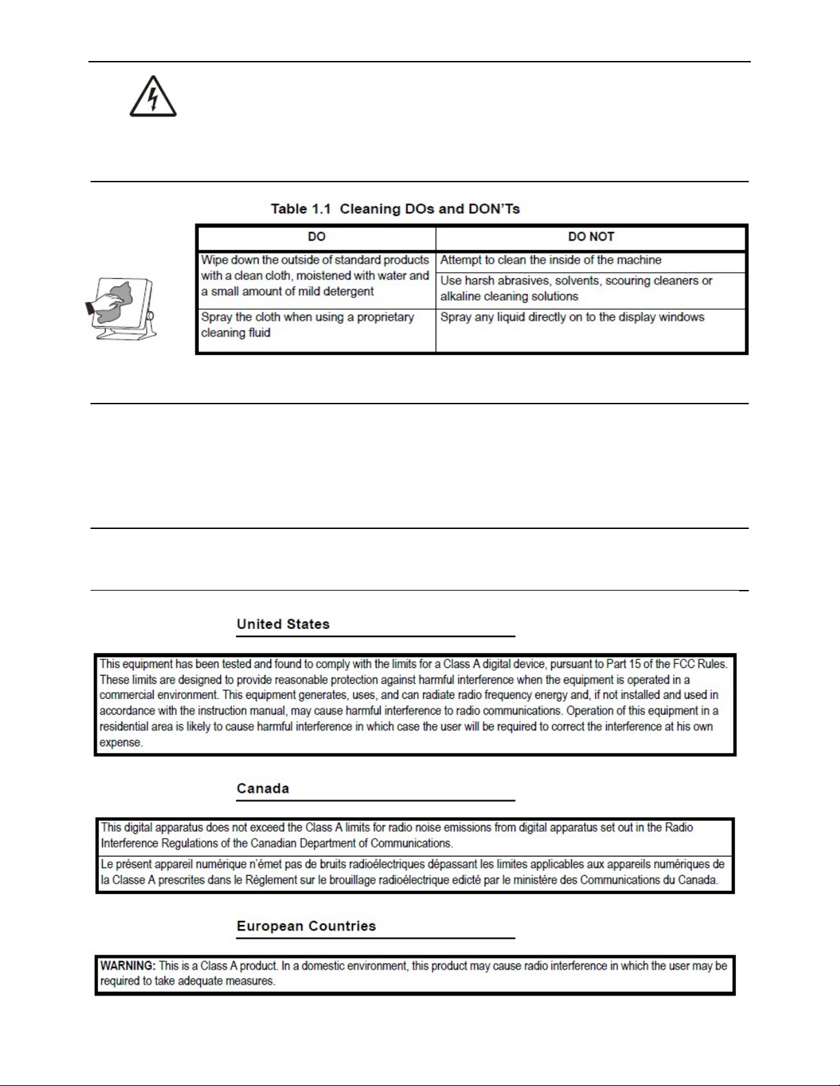
1.5 Cleaning the machine
1.6 Training
Do not attempt to operate or complete any procedure on a machine unless you have received
the appropriate training or read the instruction books.
To avoid the risk of RSI (Repetitive Strain Injury), place the machine on a surface which is
ergonomically satisfactory to the user. Take frequent breaks during prolonged usage.
1.7 Sharp objects
Do not use sharp objects such as screwdrivers or long fingernails to operate the keys.
1.8 FCC and EMC declarations of compliance
────────────────────────────────────────────────────────
6
Page 7
FI-521 Indicator Operation & Service Manual
2. Specification
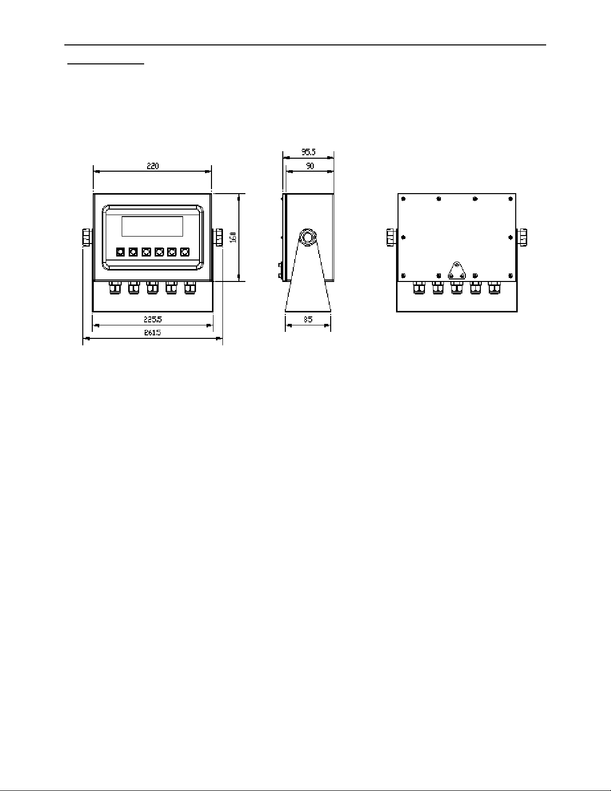
2.1 Housing and Outline Dimension:
1.2.1 IP65 wash-down stainless steel housing with adjustable bracket
1.2.2 Outline Dimension:
With bracket: 10.3" x 8.5" x 3.8" (262mm x 215mm x 96mm)
Without bracket: 8.9" x 6.3" x 3.8" (225mm x 160mm x 96mm)
Front View Side View Back View
2.2 Power Supply:
2.2.1 12 Vdc / min.500mA output AC adapter
2.3 Display:
2.3.1 FI-521: 7-digits,7-segment, 0.7’’(17mm) ultra brightness LEDs with 14 annunciators.
2.4 Keypad: 6 push buttons of SELECT, CELL, PRINT, UNIT, ZERO, ON/OFF
2.5 Environment:
2.5.1 Working temperature: -10°C to 40°C
2.5.2 Storage temperature: -20°C to 70°C
2.5.3 Humidity: 10 to 90% RH without condensation
2.5.5 Protection: IP65
2.6 Load cell Excitation:
2.6.1 Voltage: 5Vdc
2.6.2 Max. Current: 120mA (can power 8-350 ohm bridge)
2.6.3 Signal connection: 4 or 6 lead with sense leads
2.6.4 Max Sensitivity: -3mV/V to +3mV/V
2.7 Communication:
2.7.1 Serial port1: Full-duplex RS232
2.7.2 Serial port2: Full-duplex RS232 or half-duplex RS485
2.7.3 Baud Rate: Selectable: 1200-2400-4800-9600-19200-22800/38400-57600 bps
2.7.4 Data Output Format: 8N1, 7O1, 7E1
2.7.5 Protocol: selectable
2.8 Analog Circuit characters:
2.8.1 24-bit A/D converter
2.8.2 Conversion Speed: 80Hz
────────────────────────────────────────────────────────
7
Page 8

FI-521 Indicator Operation & Service Manual
2.8.3 Peak Capture Rate: 80 Hz
2.8.4 Input range: -15mV to +15mV
2.8.5 Output code: 1mV input between S+ and S- of load cell connector will output about 100,000 raw
Counts.
2.8.6 With Hardware low pass filter and 2 programmable digital low pass filters
2.9 Capacity and Division: Programmable
2.9.1 Max display range: -999,999 to 999,999
2.9.2 Max number range of all units = 100-100,000
2.9.3 Recommended Display Sensitivity: >0.5uV/ display division
2.10 Accuracy: ≤0.01%
2.11 Calibration Method:
2.11.1 Software calibration with long-term storage in EEPROM
2.11.2 Provides smooth curve fit through linearization points.
2.11.3 Calibration can be done under kgf or lbf weight unit with 10% -100%FS standard weight
2.12 Real Clock: built-in nonvolatile real time & date
2.13 Remote Digital Input:
2.13.1 There are four external inputs
2.13.2 Function: each input can be defined to HOLD, ZERO, TARE, PRNT, UNIT, OFF or NONE
2.14 Digital Output (Set point Output):
2.14.1 There are two configurable outputs
2.14.2 Each digital output combined with a digital comparator: if current force is over or less than the set
force point, the corresponding output will change its output electronic state according to the
pre-configuration.
2.15 Analog Voltage Output:
2.15.1 The output voltage is 0-2.5V, the output current should be limited 5mA by external circuit.
2.15.2 The accuracy of this analog voltage is 0.01% after calibration
2.16 Other Main Function:
2.16.1 Programmable Zero Range
2.16.2 Programmable automatic zero point tracking
2.16.3 Programmable motion detection window
2.16.4 Programmable auto-power off time, adjustable LED brightness
2.16.5 Available Measure Unit: kgf, lbf, Newton
2.16.6 Programmable serial output content
────────────────────────────────────────────────────────
8
Page 9
FI-521 Indicator Operation & Service Manual
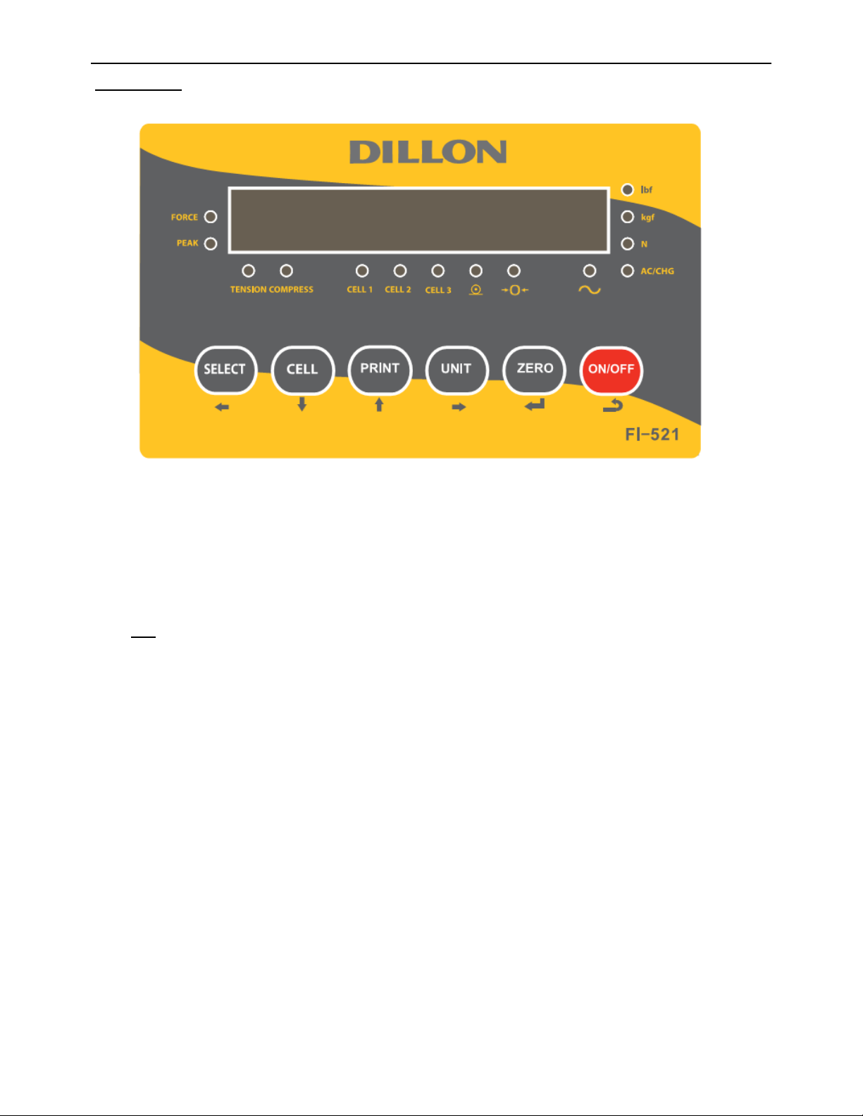
3. Faceplate
3.1 Meaning of symbol on faceplate:
3.1.1 FORCE--------Illuminates when indicator is in force display mode.
3.1.2 PEAK----------Illuminates when indicator is in peak display mode. When it’s flashing, the displayed
number is live force, when it’s steady, the number is peak force.
3.1.3 lbf,kgf,N------Illuminates the active unit of measure .
3.1.4 ----------Data Send: Illuminates when the indicator is transmitting data.
3.1.5 →0← ----------Zero: Illuminates when the indicator is within the configured center of zero.
3.1.6 ~ ----------Motion: Illuminates when the indicator detects motion (out of configured motion window).
3.1.7 TENSION, COMPRESS-----Indicates the type of force being measured.
3.1.8 CELL1, CELL2, CELL3------Show which Load Cell that is being used
3.3.9 AC/CHG
---Red when battery is being charged, Green when it’s full or not installed
────────────────────────────────────────────────────────
9
Page 10
FI-521 Indicator Operation & Service Manual
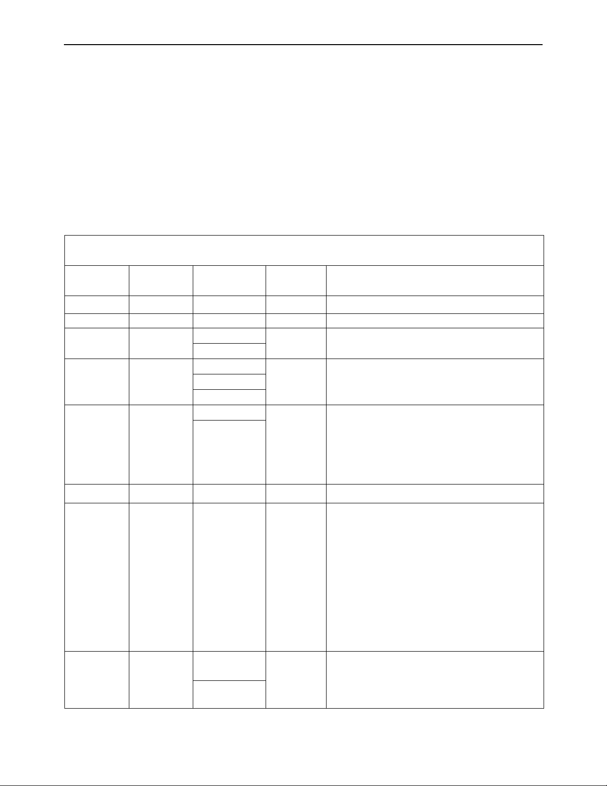
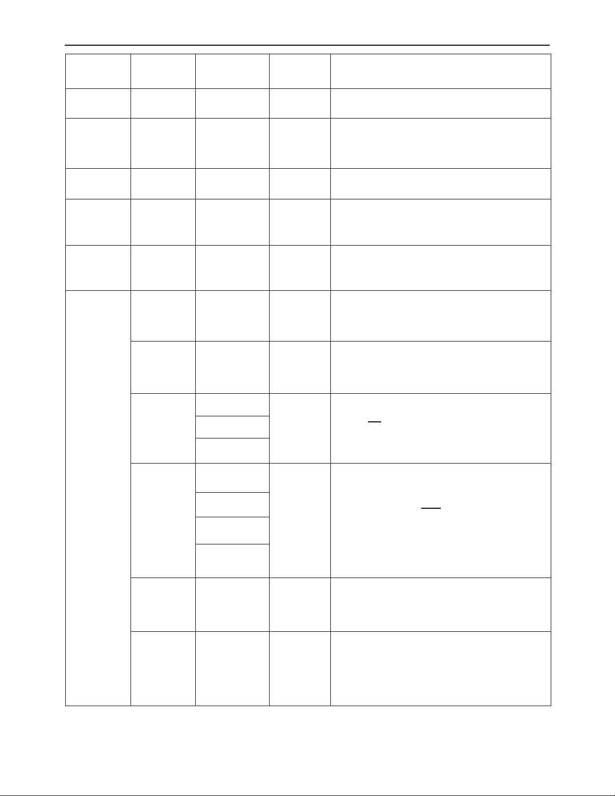
4. Summary of Key function
Key Condition Function
SELECT
CELL
PRINT
UNIT
Weighing: press less than 3 seconds To select displayed content type: Force↔Peak
Weighing: press 3 seconds or more To enter CONFIG mode
Input data mode or
Return to last sub-menu
Menu selection mode
Weighing: press less than 3 seconds To select Cell1→Cell2→Cell3→Cell1
Input data mode The digit on flashed position subtract 1
Menu selection mode To Next item of current menu
Weighing mode Output data to serial communication port
Input data mode the digit on flashed position add 1
Menu selection mode To last item of current menu
Display ADC code mode Select displaying ADC code from no-filter, filter1, filter2
Weighing mode, press less than 3
Change weighing units: lbf->kgf->N->lbf
seconds
Display date or time mode,
To set current date or time
press 3 seconds or more
Display voltage mode, press 3 seconds
To calibrate input voltage value
or more
ZERO
ON/OFF
Display ADC code, press less than 3
second
Select displaying ADC code or displaying input signal in
mV/V
Display ADC code, press 3 seconds or
To calibrate input signal in mV/V
more
Input data mode Rotate the flashed position from left to right
Weighing: press less than 3 seconds Zero function
input data mode or
Menu selection mode
To confirm input data or current item selection, and go to
next item of current menu, or next operation
Display ADC code Set or clear reference “Zero” code
Power off mode Power on
Weighing: press 3 seconds or more Power off
Input data mode ignore modification
Menu selection mode Prepare to exit from current working mode
Note:
Normally, the second function of one key is by pressing and holding down more than 3 seconds.
────────────────────────────────────────────────────────
10
Page 11
FI-521 Indicator Operation & Service Manual
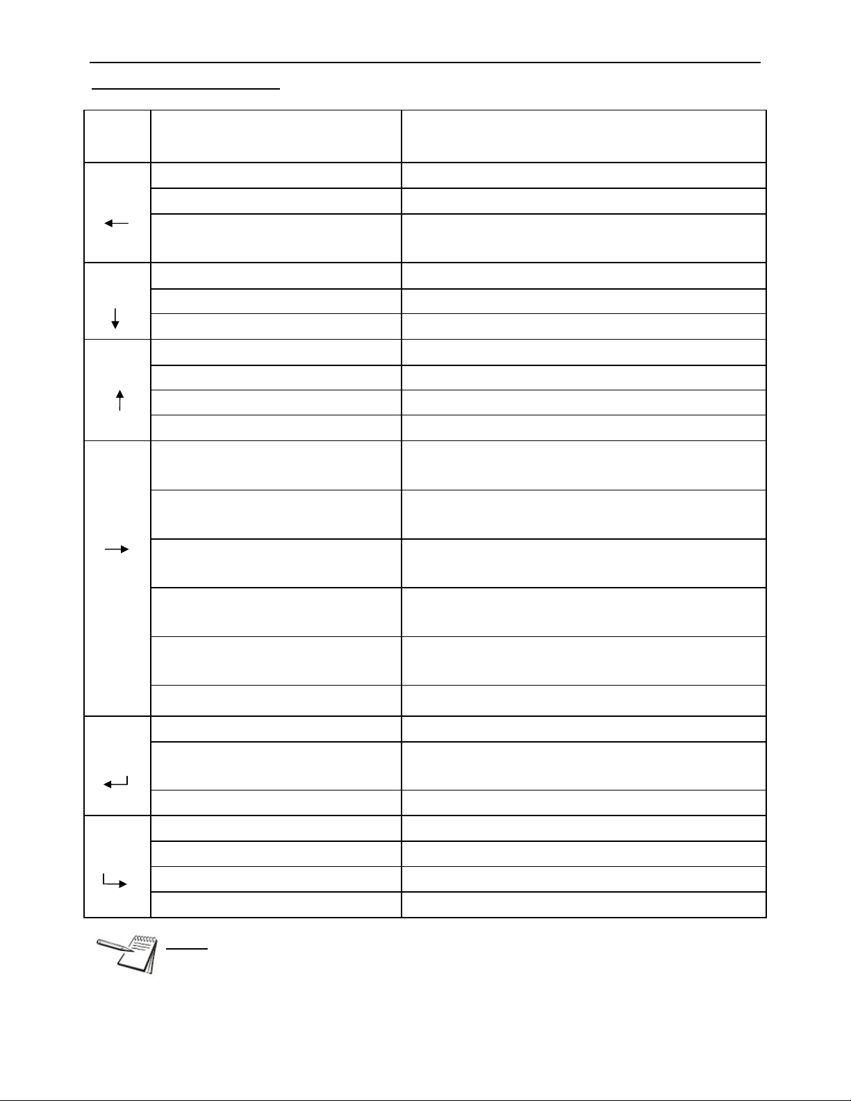
5. Operation Menu Structure
5.1 Main menu:
(Cell) (Cell) (Cell) (Cell) (Cell)
CONFIG
USER
CAL
IN.OUT
MISC
TEST
NOTE:
(1) Each LOAD CELL has its own CONFIG, CAL, IN.OUT parameters, so, before you enter
this main menu select, which load cell will be configured with the CELL key!
(2) The parameters of USER, MISC, and TEST are the same for all load cells
(3) When “Lo.VoL” or “Lo.BAT” is displayed (the voltage to PCB is low), CONFIG, USER,
CAL, IN.OUT menu can not be entered and edited .
5.2 CONFIG Submenu:
5.2.1 Access the set up mode by pressing and holding the SELECT key for 3 seconds, until display shows
CONFIG.
5.2.2 Press the ZERO key once (ZERO key is your Enter key)
5.2.3 Display will show CFG.ON or CFG.OFF
a. If it shows CFG.OFF, then you will need to move the switch in the back of the indicator,
through the CAL. Switch cover. Cycle power of the indicator and start at step #1 again.
5.2.4 Press the ZERO key once. Display shows RESET
5.2.5 Pres the CELL key until display shows CELL.TY
5.2.6 Press ZERO key once. Display shows TS.CP
5.2.7 Press ZERO key once. Display shows CELL.TY
5.2.8 Press CELL key once. Display shows DSP.POL
5.2.9 Press ZERO key once. (Select NEG or POS)
5.2.10 Press ZERO to accept
5.2.11 Press CELL key to PRIM.N
5.2.12 Press ZERO key. Display shows 10,000
a. This is number of Divisions. Use the chart below as a reference
CAPACITY is based on RESOLUTION
Capacity & Count by
Required (LBS)
PRIM.N PRIM.D
500 X 0.1 5,000 .1
2,000 X 0.5 4,000 .5
5,000 X 1 10,000 .5
10,000, X 2 10,000 1
50,000 X 10 5,000 10
** Take your Capacity and divide by your desired count-by (PRIM.D) will give you your PRIM.N number
** Example = 5,000 lb load cell divided by .5 lbs will give you 10,000
5.2.13 Press UNIT key to change to the desired number you want to change. Stop when your digit is flashing.
5.2.14 Press CELL key or PRINT key to change a number
5.2.15 Once you have set your DIVISION press ZERO to accept. Display shows PRIN.N
────────────────────────────────────────────────────────
11
Page 12
FI-521 Indicator Operation & Service Manual
5.2.16 Press CELL key. Display shows PRIM.D
5.2.17 Press ZERO key once. Display shows 1
5.2.18 Press CELL key or PRINT key to change the digit
a. Once you make a choice press ZERO key to accept
5.2.19 Press CELL key. Display shows PRIN.
5.2.20 Press ZERO key. Display shows LbF
a. Press CELL key to toggle between kgF or LbF
5.2.21 Press ZERO key to accept
5.2.22 Press ON/OFF key twice
5.2.23 Display will cycle software version, then capacity, then go to normal weighing mode.
5.2.24 Move CAL. Switch back to CFG.OFF (if you want to lock calibration)
CONFIG
SubMenu1 SubMenu2 Option Default Remark
CFG.ON seal switch is on
CFG.OFF
RESET
Seal switch is off
NO
YES
NO reset configure parameters to default setting
Tension
CELL.TY
Compres
Tension
Select the connected load cell is used for
tension or compression force
TS.CP
Pos
Select the display polarity sign of positive or
negative for the connected load cell. When
CELL.TY = TS.CP, “DSP.POL=POS” indicates
DSP.POL
Neg
Pos
that the inner code increased direction is
tension direction; “DSP.POL=Neg” indicates
that inner code decreased direction is tension
direction.
PRIM.N 100 – 100,000 10,000 the division number under primary unit
PRIM.D
0.0001,
0.0002,
0.0005,
0.001,
0.002,
0.005,
0.01,
0.02,
1
The division value under primary unit; the
division value under second unit is
automatically determined by indicator according
to the division value under primary unit.
0.05,
0.1, 0.2, 0.5,
1, 2, 5,
10, 20, 50
PRIM.Ut
KGF
LBF
LBF
────────────────────────────────────────────────────────
Select the primary unit from kg or lb, the second
unit is the lb if kg selected as primary unit or kg
if lb selected as primary unit; the calibration
standard weight must be in primary unit!
12
Page 13
FI-521 Indicator Operation & Service Manual
SECOND.N 100-125,000 10,000
NEWTON.N 100 – 125,000 10,000
the division number under second unit ,the max
is 1.25*(PRIM.N),
the division number under the NEWTON
unit ,the max is 1.25*(PRIM.N),
units that can use UNIT key to select:
UNITS 0-6 6
0=kgf, 1=lbf, 2=N(Newton), 3= kgf,lbf,
4=kgf,N, 5=lbf,N, 6=kgf,lbf,N
refer to section5.12 for some limitation
MOTION 1-255 4 Check motion window: 1-255=±0.25d *(1-255)
over load display limitation:
OVER.LD 0-100 0
0=FS+9d,
1-100=101%FS to 200%FS
FS+(0%FS to 255%FS), If the force has exceed
ABUSE 0-255 20%
this level, it’s considered to be abusive to the
load cell
ZRO.PNT
P.IZSM 0-100 10
Initial zero(power on zero) point range:
0=no limitation,
1-100= (calibration zero point) + 1%FS to
(calibration zero point) +100%FS
Initial zero(power on zero) point range:
N.IZSM 0-100 10
0=no limitation,
1-100= (calibration zero point) - 1%FS to
(calibration zero point) -100%FS
IN.IZSM
FORCE
Which force will works as initial zero point when
force is in IZSM range:
CAL.ZRO
FORCE
FORCE= current force ;
CAL.ZRO= calibration zero;
LAST.ZRO
LAST.ZRO=switch-off zero force
OV.IZSM
DSP.OVR
Choose which force will works as initial zero
FORCE
DSP.OVR
CAL.ZRO
point when force is over IZSM range:
DSP.OVR=display initial zero point is over;
FORCE= current force;
CAL.ZRO= calibration zero;
LAST.ZRO=switch-off zero force
LAST.ZRO
Zero key range:
SAZSM 0-100 2
0=no limitation,
1-100= (initial zero point) ±1%FS to (initial
zero point) ±100%FS
Zero tracking window:
AZSM 0-255 2
0=0d, no tracking;
1-255=±0.25d*(1-255)
────────────────────────────────────────────────────────
13
Page 14
FI-521 Indicator Operation & Service Manual
FILTER
FLT1.TH 0-255 40
FLT1.ST 1-64 8
FLT2.TH 0-255 20
FLT2.ST 0-255 160 Digital filter2 intensity: 0-255=weak to strong
FUNC F.ADJ
PEAK Threshd
Enter digital filter1 threshold:
0=no filter1;
1-254=filter1 be used only when vibration in
±0.5d*(1-254) ;
255= filter1 be always used
Digital filter1 intensity: 1-64 ADC’s data will be
averaged
Enter digital filter2 threshold: 0=no filter2;
1-254=filter2 be used only when vibration in
±0.5d*(1-254) ; 255= filter2 be always used
YES
NO
NO
Enable or disable fine-adjust force number in
normal force measure mode
5-65535d, When reverse varying(Threshold) of
5-65535 10
force is over this value, one peak is occurred
and will be captured
────────────────────────────────────────────────────────
14
Page 15

FI-521 Indicator Operation & Service Manual
5.3 USER Submenu:
To enter this parameter, press and hold the SELECT key for 3 seconds until display shows CONFIG. Press
CELL key to USER. Press ZERO key to RESET and press CELL key to COM1.
USER
Sub-
Menu1
SubMenu2 Option Default
RESET NO
YES
NO reset user parameters to default setting
Remark
COM1 BAUD.RT 1200
2400
4800
9600
9600 selection of com1's baud rate
19200
38400
57600
BYT.FMT
8N1
7O1
8N1
7E1
selection of com2's byte format:
(1) 8N1=8 data bits, No parity check bit, 1 stop bit;
(2) 7O1=7 data bits,1Odd parity check bit, 1 stop
bit;
(3)7E1=7 data bits, 1 Even parity check bit, 1 stop
bit;
OUT.MOD
NONE
CONT
Selection com1 output mode:
(1)NONE= COM1 disabled;
(2)CONT=continuously output;
(3)PRINT=output after PRINT key pressed;
PRINT
CMD
PRT.CMD
(4)CMD=output after a request command is
received;
(5)PRT.CMD= output after PRINT key pressed or
request command received;
PRT.CMD
(6)STABLE=output after indicator is stable;
STABLE
LAYOUT
MULTPL
MULTPL
SINGLE
Note: use PRINT or CMD to output data, the
indicator must be stable.
com1 output content and format set:
(1)MULTPL= the following selected item in OUT1
will be output use defined format;
(2)SINGLE= only displayed content and current
status will be output, it’s compatible with
NCI-SCP01
OUT1 TITLE
IND.ID
CELL.No
CELL.TYP
DSP.POL
FORCE
PEK.VLY
────────────────────────────────────────────────────────
YES
NO
YES
NO
YES
NO
YES
NO
YES
NO
YES
NO
YES
NO
NO
NO
NO
NO
NO
YES
NO
Yes/No=enable/disable output prompt of every
output line
Yes/No=enable/disable output indicator's ID
number, Prompt is “IND. ID”
Yes/No=enable/disable output load cell’s ID
number, Prompt is “CELL No.”
Yes/No=enable/disable output load cell’s type,
Prompt is “CELL TYPE”
Yes/No=enable/disable output load cell’s measure
type, Prompt is “DSP.POL”
Yes/No=enable/disable output gross force.
Prompt is “FORCE”
YES/NO=enable/disable output current captured
peak value and valley value; prompt is “PEAK”
and “VALLEY”
15
Page 16

FI-521 Indicator Operation & Service Manual
OUT1
MAX.MIN
DATE YES
TIME
AD.CODE
IN. mV/V YES
BAT.VOL
STATUS YES
B.LINE
COM2 BAUD.RT
BYT.FMT
OUT.MOD
LAYOUT
LC.ADDR
EN.ADDR
YES
NO
NO
YES
NO
YES
NO
NO
YES
NO
NO
NONE,
LINE1 –9
NO
NO
NO
NO
NO
NO
NO
LINE1
YES/NO=enable/disable output max peak and
valley value, prompt is “Max.”/ “Min.”
Yes/No=enable/disable output date. Prompt is
“DATE”
Yes/No=enable/disable output time. Prompt is
“TIME”
Yes/No=enable/disable output ADC's code.
Prompt is “A/D CODE”
Yes/No=enable/disable output input signal in
mV/V unit, Prompt is “INPUT”
Yes/No=enable/disable output voltage of battery.
Prompt is “VOLTAGE”
Yes/No=enable/disable output indicator's status.
Prompt is “STATUS”
How many blank lines after strings output:
None,LINE1-9=there're 0 - 9 blank lines after
strings
1200
2400
4800
9600
9600 selection of com2's baud rate
19200
28800
57600
8N1
7O1
8N1
selection of com2's byte format:
1)8N1=8 data bits, No parity check bit, 1 stop bit;
2)7O1=7 data bits,1Odd parity check bit,1stop bit;
3)7E1=7 data bits, 1Even parity check bit, 1stop
7E1
NONE
bit
Selection com2 output mode:
(1)NONE= COM2 disabled;
CONT
(2)CONT=continuously output;
(3)PRINT=output after PRINT key pressed;
PRINT
PRT.CMD
CMD
(4)CMD=output after a request command is
received;
(5)PRT.CMD= output after PRINT key pressed or
request command received;
PRT.CMD
STABLE=output after indicator is stable;
Note: use PRINT or CMD to output data, the
STABLE
indicator must be stable.
com2 output content and format set:
MULTPL
MULTPL
SINGLE
(1)MULTPL= the following selected item in OUT2
will be output use defined format;
(2)SINGLE= only displayed content and current
status will be output, it’s compatible with
NCI-SCP01
01-99 01 Local address for COM2, “00” is broadcast addr.
NO
NO
YES
Yes/No=enable/disable using com2 local address
in output or input strings
────────────────────────────────────────────────────────
16
Page 17

FI-521 Indicator Operation & Service Manual
OUT2 TITLE
IND.ID
CELL. No
CELL.TYP
DSP.POL
FORCE
PEK-VLY
YES
NO
YES
NO
YES
NO
YES
NO
YES
NO
YES
NO
YES
NO
NO
NO
NO
NO
NO
YES
NO
Yes/No=enable/disable output prompt of every
output line
Yes/No=enable/disable output indicator's ID
number, Prompt is “IND. ID”
Yes/No=enable/disable output load cell’s ID
number, Prompt is “CELL No.”
Yes/No=enable/disable output load cell’s type,
Prompt is “CELL TYPE”
Yes/No=enable/disable output load cell’s measure
type, Prompt is “DSP.POL”
Yes/No=enable/disable output gross force.
Prompt is “FORCE”
YES/NO=enable/disable output current captured
peak and valley value; prompt is “PEAK” and
“VALLEY”
MAX.MIN
DATE
TIME
AD.CODE
IN. mV/V
BAT.VOL
STATUS
B.LINE
BEEP KEY
YES
NO
YES
NO
YES
NO
YES
NO
YES
NO
YES
NO
YES
NO
NONE,
LINE1 –
LINE9
YES
NO
NO
NO
NO
NO
NO
NO
NO
LINE1
YES
YES/NO=enable/disable output max peak and
valley value, prompt is “Max.” and “Min.”
Yes/No=enable/disable output date. Prompt is
“DATE”
Yes/No=enable/disable output time. Prompt is
“TIME”
Yes/No=enable/disable output ADC's code.
Prompt is “A/D CODE”
Yes/No=enable/disable output input signal in
mV/V unit, Prompt is “INPUT”
Yes/No=enable/disable output voltage of battery.
Prompt is “VOLTAGE”
Yes/No=enable/disable output indicator's status.
Prompt is “STATUS”
How many blank lines after strings output:
NONE,LINE1 – LINE9=there're none,1 - 9 blank
lines after strings
Yes/No=enable/disable beep after a key pressed
down
MAX
MIN
PEAK Display
PEAK
MAX
VALLEY
────────────────────────────────────────────────────────
Select what is displayed In peak display mode:
MAX=Max. Force value;
MIN=Min. Force value;
PEAK=current captured peak value;
VALLEY=current captured valley value;
17
Page 18

FI-521 Indicator Operation & Service Manual
OTHER
NLD.RNG 1-255 10
CMD.SRC
NONE
COM1
COM1
COM2
COM1-2
A.OFF.T 0-255 0
OFF.MOD
OFF
DSP.TIM
DSP.DAT
OFF
AC.TIME
AC.DATE
1-255=the range of force is ±1-255d; when
current force is less than this value, the load cell
can be regarded as no load on it. It must be bigger
than (CONFIG.MOTION).
Source of the executed command selection:
NONE=no command will be executed;
COM1= command from COM1 will be executed;
COM2= command from COM2 will be executed;
COM1-2= command from COM1 or COM2 will be
executed;
Auto off time:
0=not auto power off;
1-255=auto power off after 1-255 minutes, in this
period, it should be no operation or no weight
changing
Auto off mode:
(1)OFF=turn off instrument;
(2)DSP.TIM= display time;
(3)DSP.DAT=display date;
(4)AC.TIME=turn off when only battery is used,
display time when AC adaptor is used;
(5)AC.DATE=turn off when only battery is used,
display date when AC adaptor is used;
LED brightness level set:
BRT1-BRT2-BRT3-BRT4-BRT5=low - middle high; only available on LED version
LED.BRT
IND.ID
BRT1-2-3-4-
5
000000 -
999999
BRT4
123456 Indicator’s ID number: 000000-999999
────────────────────────────────────────────────────────
18
Page 19

FI-521 Indicator Operation & Service Manual
5.4 CAL Submenu:
To enter this parameter, press and hold the SELECT key for 3 seconds until display shows CONFIG. Press
CELL key (2x) to CAL. Press ZERO key to enter Cal Menu.
CAL
SUBMENU1 SUBMENU2 OPTION REMARK
CAL.ON Seal switch is on
CAL.OFF
ZERO
Seal switch is off
LINE CAL.P0
CAL.P1
END.Y
CAL.P2
END.Y
CAL.P3
END.Y
CAL.P4
END.Y
CAL.P5
INPUT
CAL.END
Only do zero point calibration, then go to CAL.END to
end. (Only needed when a zero shift has occurred.)
Line calibration point0: do zero point calibration,
this point can't be omitted.
Line calibration point1: do first weight point
calibration, this point can't be omitted and standard
weight must be over 10%FS.
YES
NO
End calibration? YES=go to CAL.END to end; NO=go
to do next point calibration
Line calibration point2: do second weight point
calibration, standard weight must be over 10%FS and
be larger than it in CAL.P1, this point can be omitted.
YES
NO
End calibration? YES=go to CAL.END to end; NO=go
to do next point calibration
Line calibration point3: do third weight point
calibration, standard weight must be over 10%FS and
be larger than it in CAL.P2, this point can be omitted.
YES
NO
End calibration? YES=go to CAL.END to end; NO=go
to do next point calibration
Line calibration point4: do forth weight point
calibration, standard weight must be over 10%FS and
be larger than it in CAL.P3, this point can be omitted.
YES
NO
End calibration? YES=go to CAL.END to end; NO=go
to do next point calibration
Line calibration point5: do fifth weight point
calibration, standard weight must be over 10%FS and
be larger than it in CAL.P4, this point can be omitted.
Input or view calibration parameters value that is got
before
Calibration end and restart
NOTE:
The details can be referred in section “7.CALIBRATION”
────────────────────────────────────────────────────────
19
Page 20

FI-521 Indicator Operation & Service Manual
5.5 IN.OUT Submenu:
IN.OUT
SUB-
MENU1
INPUT INx. yyyy
SUB-
MENU2
MODE OUTx.yz
OUTPUT
SPF1 0kgf
SPF2 0kgf
OFF
MODE
ON
2.5V-F 3000kgf
AVOUT
SUB-
MENU3
DEFAULT REMARK
IN1.SELE
IN2.CELL
IN3.UNIT
IN4.ZEO
Select function(yyy) of each remote input(x)
X=1-4; yyyy=SELE(select)/ CELL(cell)/ PRNT(print)/
UNIT(unit)/ ZERO(zero)/ OFF/ NONE(none); normally,
one remote input is low (0), that means one external
switch is closed
OUT1.00
OUT2.00
Select output(x) level after power on(y) and after an event
trigger(z); x=1-2, y=0-1, z=0-1; Normally, y/z=0 will make
external relay closed, and y/z=1 make the relay open
Select the force unit of OUTPUT1 referred:
→lbf→N→kgf
kgf
; and Input the force number of
OUTPUT1 referred: 0 to FS
Select the force unit of OUTPUT2 referred:
→lbf→N→kgf
kgf
; and
Input the force number of OUTPUT2 referred: 0 to FS
OFF OFF/ON=analog voltage output is off/on
Select the controlling force unit: kgf→lbf→N→kgf
Input the force value or capacity that you want to the
2.5VDC reference: 10%FS to 120%FS. Default is 10,000.
0.0000 V
CAL.VO
1.2500 V
------------
To set and check the output voltage of
0.0000/1.2500/2.5000VDC
2.5000 V
4.6 MISC Submenu:
MISC
SUBMENU1 REMARK
CODE
VOL
display ADC's code, this code can be after no-filter, filter1 or filter2; or display input
signal in mV/V; details refer to section8
display voltage; calibrate voltage; set full charged voltage and low battery voltage;
details refer to section9
────────────────────────────────────────────────────────
20
Page 21

FI-521 Indicator Operation & Service Manual
DATE display date and set date; details refer to section11
TIME display time and set time; details refer to section10
VER display firmware version; details refer to section12
COM2.TY Display type of COM2; details refer to section13
ABUS.CNT View times of occurred abuse on selected cell; details refer to section14
ZERO.OFS ZERO OFFSET: Current zero - Calibration zero; details refer to section15
5.7 TEST Submenu:
TEST
SUBMENU1 REMARK
DISP.tst test LCD or LED; details refer to section17
COM1.rd test COM1 receiving; details refer to section20
COM1.td test COM1 transmitting; details refer to section21
COM2.rd test COM2 receiving; details refer to section20
COM2.td test COM2 transmitting; details refer to section21
KEY.tst test keys and buzzer; details refer to section17
INPUT To view the level of input lines; details refer to section18
OUTPUT To set and check output level of output lines ; details refer to section19
────────────────────────────────────────────────────────
21
Page 22

FI-521 Indicator Operation & Service Manual
6. Normal Force Measure mode
6.1 During key operation, please note to use the second function of a key, press the key down over 3 seconds;
to input data or select menu, use to process.
6.2 Power on indicator: when indicator is off, short press ON/OFF key to turn on;
Power off indicator: when indicator is on, long press ON/OFF key to turn off the indicator.
6.3 To select which load cell is connected to this indicator: press and release CELL key; after this, the indicator
will display new load cell capacity and related configuration parameters will be called and used in later
operations.
6.4 To send data out through RS232 or RS485: press PRINT key when system is stable
6.5 To zero display, presses ZERO key to set new zero point when the system is stable and within the zero
range. Please refer its range in COFIG-ZRO.PNT-SAZSM
6.6 To change measure unit: Short press UNIT key to select lbf, kgf or Newton unit. Note: under some
condition, some measure units are not available. Please refer the following Tables.
6.7 To set configuration parameters, set user parameters, set current date or time, set other parameters, or do
calibration mode, or test some hardware… Press SELECT key more than 3s to enter SETUP mode.
After entering setup mode, the MAIN MENU item CONFIG will be shown first, and then you can use
keys to select wanted submenu and wanted menu item,
select wanted choice, set wanted number, confirm and save data, or exit this mode. Please refer the
“4.Operation Menu Structure”.
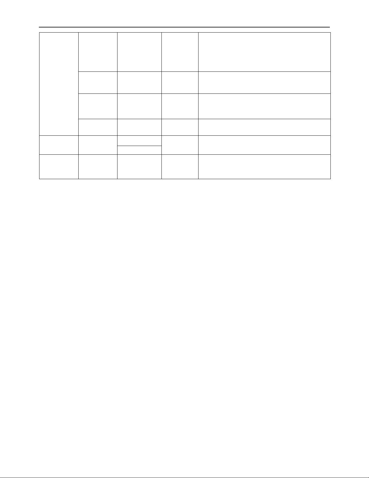
6.8 To display FORCE or Captured PEAK data: press SELECT key. In PEAK display mode, what peak will be
displayed is determined by setting of USER-PEAK-DISPLAY. Pleas refer following Fig.
Force
0
Max.
CONFIG-PEAK-THRESHOLD
Valley
Peak
Valley Min
Peak
Peak
Current
Captured
Peak
Current
Captured
Valley
Time
CONFIG-PEAK-THRESHOLD
────────────────────────────────────────────────────────
22
Page 23

FI-521 Indicator Operation & Service Manual
Table1: use Kgf as primary unit:
Calibration division value
Display division value in different weight unit that can be used
Kgf Lbf Newton
0.0001kgf 0.0001 0.0002 0.001
0.001kgf 0.001 0.002 0.01
0.01kgf 0.01 0.02 0.1
0.1kgf 0.1 0.2 1
1kgf 1 2 10
10kgf 10 20 Not available
0.0002kgf 0.0002 0.0005 0.002
0.002kgf 0.002 0.005 0.02
0.02kgf 0.02 0.05 0.2
0.2kgf 0.2 0.5 2
2kgf 2 5 20
20kgf 20 50 Not available
0.0005kgf 0.0005 0.001 0.005
0.005kgf 0.005 0.01 0.05
0.05kgf 0.05 0.1 0.5
0.5kgf 0.5 1 5
5kgf 5 10 50
50kgf 50 Not available Not available
Table2: use lbf as primary unit:
Calibration division value
Display division value in different weight unit that can be used
kgf lbf Newton
0.0001lbf Not available 0.0001 Not available
0.001 lbf 0.0005 0.001 0.005
0.01 lbf 0.005 0.01 0.05
0.1 lbf 0.05 0.1 0.5
1 lbf 0.5 1 5
10 lbf 5 10 50
0.0002 lbf 0.0001 0.0002 0.001
0.002 lbf 0.001 0.002 0.01
0.02 lbf 0.01 0.02 0.1
0.2 lbf 0.1 0.2 1
2 lbf 1 2 10
20 lbf 10 20 Not available
0.0005 lbf 0.0002 0.0005 0.002
0.005 lbf 0.002 0.005 0.02
0.05 lbf 0.02 0.05 0.2
0.5 lbf 0.2 0.5 2
5 lbf 2 5 20
50 lbf 20 50 Not available
────────────────────────────────────────────────────────
23
Page 24

FI-521 Indicator Operation & Service Manual
7. Calibration
7.1 Select the load cell (1-3) for recalibration with the cell key. If the load cell has not been configured; you will
have to access the CONFIG submenu and select the load cell parameters
Access the calibration mode by pressing theSELECT key for 3 seconds or more, until you see Config
displayed.
7.2 Press theCELL key to select the Cal menu
7.3 Press the ZERO key to enter the calibration menu.
a. After entering this mode, the history of calibrations will be shown first. This number will be
increment one digit after every calibration and calibration data saved.
b. After the counter number above was displayed, it will show “CAL.OFF” or “CAL.ON” which
depends on whether the sealed calibration switch is OFF or ON. If CAL OFF is displayed, you
can still do calibration but the result will not be saved. To turn CAL ON, power down the unit and
flip the switch located on the back of the indicator under the triangle stainless steel plate, and
power back on and follow the step above.
7.4 Press the ZERO key to go to next step.
7.5 Press theCELL key to scroll to LINE
7.6 When LINE is displayed, press theZERO key to enter linearity calibration.
7.7 CAL.PO will be displayed with a zero value. Remove all weight on the scale and then press theZEROkey
to confirm zero point calibration. The zero weight will flash while capturing the zero point. After getting
the zero-point data, the zero weight will become steady and proceed to the next step.
7.8 When first default standard weight is display after CAL.P1being shown. The default standard weight is
100% of full scale. Using the SELECT, PRINT, CELL, UNIT keys to input the value of the loaded weight.
Minimum test weight value 10% of full scale.
7.9 Put corresponding weight onto the scale
7.10 Press theZERO key to confirm the calibration.
7.11 If calibration was successful, display will show END.Yand the Y is flashing. It is waiting for a command
to go onto the next calibration point or exit the calibration mode. Use the CELLorPRINTkey to select
End.y for yesor End.n for no.
a. If yes is selected, the calibration will be saved and exit to the force mode when the load is
removed.
b. If no is selected, it will go to the next step, requiring a higher calibration or linearization point.
7.12 Press the ZEROkey to confirm.
7.13 The first default standard weight is displayed after Cal.P2being shown. The default standard weight is
100 % of full scale. Use the SELECT, PRINT, CELL, UNIT keys to input the value of the loaded weight.
(More than 10% of full scale weight, and larger than the weight used on CAL.P1) onto scale.
7.14 If calibration was successful, display will show END.Yand the Y is flashing. It is waiting for a command
to go onto the next calibration point or exit the calibration mode. Use the CELLorPRINTkey to select
End.y for yes or End.n for no.
────────────────────────────────────────────────────────
24
Page 25

FI-521 Indicator Operation & Service Manual
a. If yes is selected, the calibration will be saved and exit to the force mode when the load is
removed.
b. If no is selected, it will go to the next step.
7.15 Press the ZERO key to confirm
7.16 The first default standard weight is displayed after Cal.P3being shown. The default standard weight is
100 % of full scale. Use the SELECT, PRINT, CELL, UNIT keys to input the value of the loaded weight.
(more than 10% of full scale weight, and larger than the weight used on CAL.P2) onto scale
7.17 Press the ZERO key to confirm
7.18 When calibration is complete CAL.ENDwill be displayed. The indicator will restart, remove the load
from the scale and the indicator will go back to the normal force mode.
8. Force Fine-tune
With this function, the user can adjust displayed force a little, and no need standard weight. But please
note:
(1)The indicator must have been calibrated before this
(2)The range of adjustment is “(current displayed force) x (0.9-1.1)”. it means the range is about ±10%
(3)The “CONFIG-F.ADJ=YES” must be set.
(4) The current unit should be the unit in PRIM.U, and the tare weight is 0.
8.1 To enter this mode, turn on indicator, after indicator displaying 0 force, put a load (suppose: its correct force
is 1230.0lb) onto load cell, then indicator will display the load’s force, say “1234.5 lb”. Press down
ON/OFF and ZERO at same time until first digit flashes, this means indicator has entered into “force
fine-tune” mode.
8.2 Use to input correct force (1230.0). Press the ZERO key, the active correct force will be
displayed and Display will stop flashing. After this, displayed force will be adjusted by this ratio
(1230.0/1234.5) and this ratio will be active until next modification on it.
8.3 To remove the effect of this ratio, there’re two ways: “8.3.1 way” and “8.3.2 way”
8.3.1 Do standard calibration, like in “6.CALIBRATION”
8.3.2 Remove all weight on scale, Press ZERO to make 0 displayed, Put a load onto load cell, a number
will be displayed, suppose it’s 1230.0lb ; Press down ON/OFF and ZERO at same time until first
digit flashes, this means indicator has entered into “force fine-tune” mode.
Press key, the displayed weight will be restored to 1234.5, and then press key to
confirm and exit to normal weighing mode.
9. View ADC output Code
9.1 In this mode, you can examine the stability of weighing system, the increment value of ADC output code
corresponding to the loaded weight.
Note:
The increment of ADC code for FS weight must be larger or equal to 10 times of selected
display division; otherwise, the calibration cannot be properly completed. e.g. The display
division is 0.1kg. Load 100kg standard weight on the platform, the increment of ADC code
should be at least more than 10x100kg/0.1kg= 10x1000=10000. In this case, the indicator can
be calibrated. Otherwise, smaller division needs to be Chosen.
The variation of ADC code should be small; otherwise, the calibration cannot properly complete
also.
────────────────────────────────────────────────────────
25
Page 26

FI-521 Indicator Operation & Service Manual
9.2 To go to this working mode, press down SETLECT until CONFIG is shown, using CELL, PRINT and ZERO
key to go to MISC - Code item, press ZERO to enter this mode and display ADC output raw code.
9.3 In this mode, first press ZERO key can set current code as a reference zero, and then to display net code,
press ZERO again to clear this reference and display gross code.
9.4 In this mode, press PRINT key to select displaying code that has been filtered by no-filter, filter1 or filter1
and filter2, and corresponding announciator N, kgf, lbf will be lighted.
9.5 In this mode, press UNIT key to select displaying ADC’s code or input signal in x.xxxxx mV/V unit. When
display in mV/V unit, all announciator of N, kgf, lbf will be lighted.
9.6 When in display signal in x.xxxxx mV/V mode, press down UNIT key to calibration input signal in mV/V.
After enter this mode, “0mV/V” will be flashed, input 0mV/V signal to load cell connector, then press ZERO
to confirm. When “1mV/V” or “2mV/V” is displayed, use UNIT key select “2mV/V” or “1mV/V”, then input
corresponding signal to load cell connector, then press ZERO to confirm. After calibration done, it backs to
display signal in x.xxxx mV/V. In above steps, press CELL or PRINT key will also back to display signal in
x.xxxxx mode. The end customer normally no need to do this calibration, it has been done in factory.
9.7 Press SELECT key to return to last menu item, press ON/OFF key to prepare to exit this mode
10. View and Set Time
10.1 After entering MAIN MENU mode (by press down SELECT key more than 3s), using PRINT or CELL key
to select MISC-TIME item, press ZERO to display current time.
Time display Format is: txx.xx.xx(hh-mm-ss) for LED Version, 24h format
Press down UNIT more than 3s to enter modification time mode. Using PRINT, CELL, UNIT, ZERO keys
to modify current time. If time of no operation s more than 5s, it will automatically exit modification mode.
Press SELECT key to return to last menu item, press ON/OFF key to prepare to exit this mode
11. View and Set Date
11.1 After entering MENU mode (by press down SELECT key more than 3s), using PRINT or CELL key to
select MISC-DATE item, press ZERO to enter MISC menu.
11.2 Date display Format is: dxx.xx.xx(yy-mm-dd) for LED Version
11.3 Press down UNIT more than 3s to enter modification date mode. Using SETLECT, PRINT, CELL, UNIT,
ZERO keys to modify current date. If time of no operation is more than 5s, it will automatically exit
modification mode.
11.4 Press SELECT key to return to last menu item, press ON/OFF key to prepare to exit this mode
12. View Firmware Version
12.1 Press down SELECT until CONFIG is shown, using PRINT or CELL key to select MISC-VER item, press
ZERO to display current Version.
12.2 Firmware Version display Format is: Vxx.yy, xx is hardware version, yy is software version
12.3 Press SELECT key to return to last menu item, press ON/OFF key to prepare to exit this mode
13. View COM2’s Type
13.1 Press down SELECT until CONFIG is shown, using PRINT or CELL key to select MISC-COM2.TY item,
────────────────────────────────────────────────────────
26
Page 27

FI-521 Indicator Operation & Service Manual
press ZERO to display COM2’s type (485, 232, None)
13.2 Press SELECT key to return to last menu item, press ON/OFF key to prepare to exit this mode
14. View the Times of Load Cell was Abused
14.1 Press down SELECT until CONFIG is shown, using PRINT or CELL key to select MISC-ABUS.CNT item,
press ZERO to show the times of selected load cell had been abused (CLx.yyy). x=1,2,3; yyy=000-999
14.2 When the indicator is not sealed and press ZERO key more than 3s, this counter can be reset to 000.
14.3 Press SELECT key to return to last menu item, press ON/OFF key to prepare to exit this mode
15. View Zero Offset
15.1 Press down SELECT until CONFIG is shown, using PRINT or CELL key to select MISC-ZERO.OFS item,
press ZERO to view the offset of current zero point and calibration zero point.
15.2 Use UNIT key to view this offset in code (xxxxxxx) or in x.xxxxx mV/V format
15.3 Press SELECT key to return to last menu item, press ON/OFF key to prepare to exit this mode
16. Display Test
16.1 Press down SELECT more than 3s to enter MAIN MENU mode, using PRINT or CELL key to select
TEST-DISP item, press ZERO to enter test display mode and all segments will be lighted first.
16.2 In this mode, every pressing of CELL key will light next segment, every pressing of UNIT will light next
digit, press ZERO will automatically light all segments and all digits.
16.3 Press SELECT key to return to last menu item, press ON/OFF key to prepare to exit this mode
17. Keyboard and Buzzer Test
17.1 Press down SELECT more than 3s to enter MAIN MENU mode, using PRINT or CELL key to select
TEST-key item, press ZERO to enter test keypad mode, and key. -- will be displayed.
17.2 In this mode, press a key, the value of this key will be displayed on - - position and buzzer will beep..
17.3 Press SELECT key to return to last menu item, press ON/OFF key to prepare to exit this mode
18. Input Test
18.1 Press down SELECT until CONFIG is shown, using PRINT or CELL key to select MISC-INPUT item,
press ZERO to show level (0/1) of input line1. “INP1.0/1” will be shown
18.2 Use CELL, PRINT to view the level of input line1,2,3,4
18.3 Press SELECT key to return to last menu item, press ON/OFF key to prepare to exit this mode
19. Output Test
19.1 Press down SELECT until CONFIG is shown, using PRINT or CELL key to select MISC-OUTPUT item,
press ZERO to output 0/1 on output line1. “OUT1.0/1” will be displayed
19.2 Use CELL key to select output 0 or 1 on output line. Use PRINT key to select test output line1 or line2.
19.3 Press SELECT key to return to last menu item, press ON/OFF key to prepare to exit this mode
20. Serial Port1/2 (COM1/2) Receiving Test
────────────────────────────────────────────────────────
27
Page 28

FI-521 Indicator Operation & Service Manual
20.1 Before test the receiving function of COM1 or COM2, a cable is need to connect a PC and this indicator,
and a software that is similar with Super Terminal of Windows is also need to run on PC to send bytes to
this indicator. Please note: testing uses USER-COM1/2-BAUD.RT setting baud rate and 8N1 byte format,
Hex data.
20.2 Press down SELECT more than 3s to enter MAIN MENU mode, using PRINT or CELL key to select
TEST-COM1.RD or TEST-COM2.RD item, press ZERO to enter test COM1/2 receiving function, and
rd1.-- or rd2.--will be displayed first.
20.3 In this mode, received hex data (0x00 – 0xff) will be displayed on -- position.
20.4 Press SELECT key to return to last menu item, press ON/OFF key to prepare to exit this mode
21. Serial Port1/2(COM1/2) Transmitting Test
21.1 Before test the transmitting function of COM1 or COM2, a cable is need to connect a PC and this
instrument, and a software that is similar with Hyper Terminal of Windows is also need to run on PC to
receive bytes from this instrument. Please note: testing uses USER-COM1/2-BAUD.RT setting baud rate
and 8N1 byte format, Hex data.
21.2 Press down SELECT more than 3s to enter SELECT mode, using PRINT or CELL key to select
TEST-COM1.TD or TEST-COM2.TD item, press ZERO to enter test COM1/2 transmitting function, and
td1.-- or td2.-- will be displayed first.
21.3 In this mode, transmitted hex data (0x00 – 0xff) will be displayed on -- position, and PRINT, CELL, UNIT,
ZERO keys can be used to modify transmitted data.
21.4 Press SELECT key to return to last menu item, press ON/OFF key to prepare to exit this mode
22. Remote Input Function Selection
22.1 Press down SELECT until CONFIG is shown, using PRINT or CELL key to select IN.OUT-INPUT item,
press ZERO to display original function of input line1.It is displayed in “Inx.yyyy) format. X(=1,2,3,4) is the
number of input line, yyyy(=NONE, SELE, CELL, PRNT, UNIT, ZERO, OFF) is the function of input line x.
Every input function can be defined to SELECT,CELL,PRINT,UNIT,ZERO, or OFF.
22.2 Use CELL key to change input line; Use PRINT key to select the function of this line, Use ZERO key to
confirm and save.
22.3 Press SELECT key to return to last menu item, press ON/OFF key to prepare to exit this mode
23. Output Setting
23.1 Press down SELECT until CONFIG is shown, using PRINT or CELL key to select IN.OUT-OUTPUT item,
press ZERO to enter setting mode.
23.2 Use CELL or PRINT key to select MODE (setting output mode) or SPF1 or SPF2 (“Set Point Force”,
setting the corresponding data of output). Use ZERO to confirm.
23.3 When “OUTx.yz” is shown, Use CELL key to change output line number(x), Use PRINT key to change
level after power on (y) and after an event trigger(z); x=1-2, y=0-1, z=0-1; Normally, y/z=0 will make
external relay closed, and y/z=1 make the relay open. y=0/1 means after the indicator power on, the
output level is 0/1, z=0/1 means if current display force is over the setting data (SPF1/2), the output level is
0/1. Use ZERO to confirm.
────────────────────────────────────────────────────────
28
Page 29

FI-521 Indicator Operation & Service Manual
23.4 When “SPF1/2” is shown, use ZERO to enter set set-point1/2 data mode. When “UNIT.kgf/lbf/n” is shown,
use CELL, PRINT, or UNIT key to select unit of input force number. After this, use CELL, PRINT, UNIT
key to input force number, and then use ZERO to confirm and save them.
23.5 In normal force measure mode, if SPF1 or SPF2 is set bigger than 0, the electronic level on output line will
change according to the setting of OUTx.yz.
23.6 Press SELECT key to return to last menu item, press ON/OFF key to prepare to exit this mode
24. Analog Voltage Output Setup
Note:
The current draw from analog voltage output should be less than 2.5mA, that means the resistor
M
added on this output connector should more than 1K
!
24.1 Press down SELECT until CONFIG is shown, using PRINT or CELL key to select IN.OUT-AVOUT item,
press ZERO to enter this mode.
24.2 Use CELL or PRINT key to select MODE (set analog voltage output is enable or disable) or 2.5V-F (set
the force number of 2.5V output) or CAL.VO (calibrate the output analog voltage). Use ZERO to confirm.
24.3 After enter MODE item, use CELL and PRINT to enable or disable output analog voltage, Use ZERO to
confirm.
24.4 After enter 2.5V-F item, “UNIT.kgf/lbf/n” will be shown, use CELL, PRINT, or UNIT key to select unit of
input force number, then use CELL, PRINT, UNIT to input force number that is corresponding to the 2.5V
analog voltage output, Use ZERO to confirm.
24.5 When CAL.VO is shown, it means calibrate output voltage. Before this, a high accuracy voltage meter is
need. After enter this calibration mode by pressing ZERO key, “0.0000V” will be shown, that means output
0.0000V is ready to be calibrated. if the reading on voltage meter is not 0.0000V, use CELL or PRINT to
adjust the reading to 0.0000V, then use ZERO key to finish 0.0000V output calibration. Similarly, do
calibration on 1.2500V and 2.5000V. When adjust the output voltage, the output code to DAC (Digit to
Analog Converter) will be displayed temporally and then back to display output voltage.
24.6 Press SELECT key to return to last menu item, press ON/OFF key to prepare to exit this mode
25. Details about Serial Communication
25.1 COM1 is RS232, communication wires come from RS232 connector, and TXD1, RXD1 and GND are
used.
25.2 COM2 can be RS232 or RS485, if used as RS232, communication wires come from RS232 connector,
and TXD2, RXD2 and GND are used, if used as RS485, communication wires come from RS485
connector, and A and B are used (if need GND or +5VCC1 can be used).
Please refer to section 26.2, 26.3.4-5, 26.3.7-9 for jumper connector details.
25.3 The baud rate and byte format is set by USER-COM1/2-BAUD.RT and USER-COM1/2-BYT.FMT.
Responses to serial commands will be immediate, or within one force measure cycle of the indicator. One
second should be adequate for use as a time-out value by remote (controlling) device.
25.4 The length of each item in a transition string:
25.4.1 Reading data --- 6bytes
Data polarity ----1byte: “-” for negative, and followed the first digit; “ ” for positive.
Decimal point ---1byte: “.”
────────────────────────────────────────────────────────
29
Page 30

FI-521 Indicator Operation & Service Manual
Measure unit ----1-3bytes:“ lbf”,“ kgf”, “N”, left aligned
Current status-- 4bytes
25.4.2 If the force is overcapacity, the indicator will return eight “^” characters (the field of polarity, decimal
point, force data is filled by “^”).
25.4.3 If the force is under capacity, it will return eight “_” characters (the field of polarity, decimal point, and
force data is filled by “_”).
25.4.4 If the zero point is error, it will return eight “-“ characters (the field of polarity, decimal point, and force
data is filled by “-”).
25.4.5 Useless leading 0 before digits is suppressed. Reading weight is right aligned.
25.5 Key to symbols used
<LF> Line Feed character (hex 0AH)
<CR> Carriage Return character (hex 0DH)
<ETX> End of Text character (hex 03H)
<SP> Space (hex 20H)
H
1H2H3 H4
Four current status bytes
<P> Polarity character: “-” or “ ”
W
---W
1
6
Reading data
<DP> Decimal point
U
1U2 U3
Measure units, kgf, lbf, N
<Add> Address of indicator
<Prompt> Prompt of output content
The bit definition of H
1H2H3 H4
:
Bit Byte 1 (H1) Byte 2 (H2) Byte 3 (H3) Byte 4 (H4)
0=stable 0= not under capacity
0
1= not stable 1= under capacity
0= not at zero point 0= not over capacity
1
1= at zero point 1= over capacity
0=RAM ok 0=ROM ok 0= force mode
2
1= RAM error 1=ROM error 1= peak mode
0= eeprom OK
3
1= eeprom error
0=calibration ok 0=initial zero ok 0=input4’s level is low
1=calibration error 1=initial zero error 1=input4’s level is high
0=output1 is set low 0=input1’s level is low
1=output1 is set high 1=input1’s level is high
0=output2 is set low 0=input2’s level is low
1=output2 is set high 1=input2’s level is high
0=input3’s level is low
1=input3’s level is high
4 always 1 always 1 always 1 always 1
5 always 1 always 1 always 1 always 1
6 always 0 always 1 always 1 always 0
7 parity Parity parity Parity
25.6 Communication when USER-COM1/2-LAYOUT is set to SINGLE:
25.6.1 Commands and response
25.6.1.1 Command: W<CR> (57h 0dh), request current reading
────────────────────────────────────────────────────────
30
Page 31

FI-521 Indicator Operation & Service Manual
Response:
<LF>^^^^^^^^U
<LF>_ _ _ _ _ _ _ _ U
<LF> - - - - - - - - U
Note: U
1U2 U3
<CR><LF> H1H2H3 H4<CR><ETX>---over capacity
1U2 U3
<CR><LF> H1H2H3 H4<CR><ETX>---under capacity
1U2 U3
<CR><LF> H1H2H3 H4<CR><ETX>---zero-point error
1U2 U3
is 1or 3 bytes according to current unit: kgf, lbf, N
<LF><P>W
1W2W3W4W5
<DP>W6 U1U2 U3 <CR><LF> H1H2H3 H4 <CR><ETX>---normal data
Note: The decimal point position is determined by CONFIG-PRIM.D
25.6.1.2 Command: S<CR> (53h 0dh) , request current status
Response: <LF> H
1H2H3 H4
<CR><ETX>
25.6.1.3 Command: Z<CR> (5ah 0dh)
Response: Zero function is activated (simulate ZERO key) and it returns to current indicator status.
<LF> H
1H2H3H4
<CR><ETX>
If ZERO function cannot be activated, it will return to current indicator status.
25.6.1.4 Command: U<CR> (55h 0dh)
Response: Changes units of measure (simulate UNIT key) and return indicator status with new units,
The new measure unit should be allowed to use
<LF> U
<CR><LF> H1H2H3 H4<CR><ETX>
1U2 U3
25.6.1.5 Command: L<CR> (4ch 0dh)
Response: Select next load cell to work (simulate CELL key), and returns indicator status.
<LF> H
1H2H3H4
<CR><ETX>
25.6.1.6 Command: X<CR> (58h 0dh)
Response: power off the indicator, just like press down the ON/OFF key to turn off the indicator.
25.6.1.7 Command: all others
Response: Unrecognized command <LF>? <CR><ETX>
25.6.2 Summary of Command and Response:
Command
Response
ASCII HEX
Read scale weight:
<CR><LF> H1H2H3 H4<CR><ETX>---over capacity
1U2 U3
<CR><LF> H1H2H3 H4<CR><ETX>---under capacity
1U2U3
<CR><LF> H1H2H3 H4<CR><ETX>---zero-point error
<dp>W6U1U2U3<CR><LF>H1H2H3H4<CR><ETX>---norm
W<CR> 57 0d
<LF>^^^^^^^^U
<LF>________U
<LF>-------- U
<LF><p>W
1U2 U3
1W2W3W4W5
al data
S<CR> 53 0d <LF> H1H2H3H4<CR><ETX>; read indicator status
Z<CR> 5a 0d <LF> H1H2H3H4<CR><ETX> ; simulate ZERO key
U<CR> 55 0d <LF> U1U2 U3 <CR><LF> H1H2H3H4<CR><ETX>; simulate UNIT key
L<CR> 4c 0d <LF> H1H2H3H4<CR><ETX>; simulate SELECT key
────────────────────────────────────────────────────────
31
Page 32

FI-521 Indicator Operation & Service Manual
X<CR> 58 0d power off the indicator, simulate OFF key
others
<LF>? <CR><ETX>
25.7 Communication whe n USER-COM1/2-LAYOUT is set to MULTIPLE:
25.7.1 Output string frame:
<LF><Add><Prompt><p>W
1W2W3W4W5
<Dp>W6 U1U2 U3 <CR>
…… ---- Line number and content are determined by setting of USER-OUT1/2-xxxx
<LF><Add><Prompt>H
1H2H3 H4
<CR> ---- USER-OUT1/2-STATUS is set to YES
……
<LF><Add><CR> --- USER-OUT1/2-LINE is set to LINE1…9
…… The number of blank lines is determined by USER-OUT1/2-LINE setting
<ETX> --- Last byte of string frame
25.7.2 Caution:
(1)The decimal point position is determined by CONFIG-PRIM.D
(2)The unit position and bytes is determined by which current unit is used.
(3)The details of <Prompt> refer to the content in 4.3USER Submenu.
(4)If USER-COM2-EN.ADDR is set to NO, no <Add> will be output.
(5)In continues output mode, if USER-COM1/2-LAYOUT is set to MULTIPLE, and many contents are
selected to output, the output contents from COM1 or COM2 may not catch up with the data processed
in indicator, So, if you want to watch “real time” data, you need to select fewer output contents and set
higher baud rate for COM1 or 2.
25.7.3 Examples of some layout when USER-OUT1-xxxx is set to YES:
IND. ID: 123456
CELL No. : 1
CELL TYPE: COMPRESS
DSP.POL: POSITIVE
FORCE: 123.34 lbf
PEAK: 150.60 lbf
VALLEY: 10.78lbf
Max: 192.24lbf
Min: 1.56lbf
DATE: 2012-02-12
TIME: 12:34:56
A/D CODE: 982463
INPUT: 1.23034 mV/V
VOLTAGE: 6.7V
STATUS: bpq2
────────────────────────────────────────────────────────
32
Page 33

FI-521 Indicator Operation & Service Manual
26. Sockets and Jumpers
26.1 Back View of Indicator:
With back cover without back cover
26.2 Sockets and Jumpers on Main Board
26.2.1 Without Analog Voltage Output Board:
────────────────────────────────────────────────────────
33
Page 34

FI-521 Indicator Operation & Service Manual
26.2.2 With Analog Voltage Output Board:
26.3 Definition of Sockets and Jumpers: (make sure the no.1 pin position, refer to 22.2)
26.3.1 ADP---adapter power input connector
PIN # DEFINITION IN/OUT/POWER ELECTRICAL LEVEL
1 Adapter input voltage + Power input 12Vdc(10.5-15Vdc,≥0.5A)
2 Adapter input voltage – (GND) Power ground 0Vdc
3 Shell Earth
26.3.2 BAT---Battery power input connector
PIN # DEFINITION IN/OUT/POWER ELECTRICAL LEVEL
1 Battery input voltage + Power input 5.6-7.2Vdc (6V lead acid
battery)
2 Battery input voltage – (GND) Power ground 0Vdc
26.3.3 LOADCELL Connector:
PIN # DEFINITION IN/OUT/POWER ELECTRICAL LEVEL
1 Excitation + Power output 5±0.3 Vdc (≤0.12A)
2 Sense + Power input 5±0.3 Vdc
3 Excitation- Power ground ≤0.5 Vdc
4 Sense - Power input 0Vdc
5 Signal + Signal Input 2.5±0.3 Vdc
6 Signal - Signal Input 2.5±0.3 Vdc
7 Shield - -
────────────────────────────────────────────────────────
34
Page 35

FI-521 Indicator Operation & Service Manual
If a pigtail (an around 30cm cable with a 7-pin female connector) is used for loadcell interface,the cable
pinouts are:
A: Signal -
B: Excitation +
C: Signal +
D: Excitation -
E: Sense -
F: Sense +
G: Ground
26.3.4 RS232 Connector:
PIN # DEFINITION IN/OUT/POWER ELECTRICAL LEVEL
1 COM1 Receive Input -12 to +12Vdc
2 COM1 Transmit Output -12 to +12Vdc
3 GND Power ground 0Vdc
4 GND Power ground 0Vdc
5 COM2 Receive Input -12 to +12Vdc
6 COM2 Transmit Output -12 to +12Vdc
26.3.5 RS485 Connector:
PIN # DEFINITION IN/OUT/POWER ELECTRICAL LEVEL
1 RS485 signal A Input/output 0Vdc
2 RS485 signal B Input/output 0-5Vdc
3 GND Power ground 0-5Vdc
26.3.6 CAL Jumper set:
CONNECTED PINS FUNCTION
1-2 Calibration Enabled
2-3 Calibration Disabled
26.3.7 JP4 Jumper set:
CONNECTED PINS FUNCTION
1-2 RS485 terminal 120ohm resistor on board is disabled
2-3 RS485 terminal 120ohm resistor on board is enabled
────────────────────────────────────────────────────────
35
Page 36

FI-521 Indicator Operation & Service Manual
26.3.8 JP8 Jumper Connector:
CONNECTED PINS FUNCTION
COM2 is used as RS232
COM2 is used as RS485
COM2 is not used
COM2 is not used
26.3.9 RXD2 and TXD2 Jumper Connector:
CONNECTED PINS
TXD2 RXD2
26.3.10 JP3 Jumper Connector:
CONNECTED PINS FUNCTION
FUNCTION
COM2 is not used
COM2 is used as RS232
COM2 is used as RS485
JP3-2,3 pin connected:
4 wires Load cell is used
JP3-1,2 pin connected:
6 wires load cell is used
────────────────────────────────────────────────────────
36
Page 37

FI-521 Indicator Operation & Service Manual
R
26.3.11 AVOUT Connect on Analog Voltage Output Sub-Board:
CONNECTED PINS FUNCTION
1 Analog Voltage Output +
2 Analog Voltage Output – (Internal Power GND)
Note:
The current draw from 1-2 connector should be less than 2.5mA, that means the resistor added
between 1-2 connector should more than 1K
M
!
26.3.12 XIN (Remote Input) Connector:
26.3.12.1 Pin Definition
PIN # DEFINITION IN/OUT/POWE
ELECTRICAL LEVEL
1 Internal Power output + Power output 5 - 8Vdc (≤0.1A)
2 Input1+ input 5-24Vdc
3 Input1- input 0Vdc
4 Input2+ input 5-24Vdc
5 Input2- input 0Vdc
6 Input3+ input 5-24Vdc
7 Input3- input 0Vdc
8 Input4+ input 5-24Vdc
9 Input4- input 0Vdc
10 Internal Power output - Power GND 0 Vdc
26.3.12.2 Connection Example When External Power Supply:
The remote keys RK1-RK4 also can be transistor, and the remote keys connection is isolated to internal circuit.
────────────────────────────────────────────────────────
37
Page 38

FI-521 Indicator Operation & Service Manual
26.3.12.3 Connection Example When Internal Power Supply (not recommended):
The remote keys RK1-RK4 also can be transistor, and the remote keys connection is not isolated to internal
circuit.
26.3.13 XOUT (Output) Connector:
26.3.13.1 Pin Definition
PIN # DEFINITION IN/OUT/POWER ELECTRICAL LEVEL
1 Internal Power output - Power GND 0 Vdc
2 Output driver COM /
Emitter of Output NPN Transistor 1 and 2
External Power input -
3 Output driver 1 Output, open NPN Transistor Collector 1 Sink 0.5A Max.
4 Output driver 2 Output, open NPN Transistor Collector 2 Sink 0.5A Max.
5 External Power input + Power input 5 – 24 Vdc
6 Internal Power output + Power output 5 - 8 Vdc (≤0.1A)
26.3.13.2 Connection Example When External Power Supply:
The external power is isolated by optocoupler to internal circuit in this situation. The Max. voltage of external
power should not be over than 24VDC, and should to keep the Max. current of output1 or output2 less than
0.5A .
────────────────────────────────────────────────────────
38
Page 39

FI-521 Indicator Operation & Service Manual
25.3.13.3 Connection Example When Internal Power Supply (not recommended):
When use internal power is used, the total current of output1 and output 2 draw (sink) must be less than
0.1A, that means heavy extra load should not be added on internal power! As above drawing, only light
load can be used in this condition.
────────────────────────────────────────────────────────
39
Page 40

FI-521 Indicator Operation & Service Manual
27 Meaning of Some Symbols and Troubleshooting
27.1 Meaning of Symbols:
27.1.1 0﹉﹉﹉﹉ ------ Zero is over the setting range
27.1.2 0﹍﹍﹍﹍ ------ Zero point is below the setting range
27.1.3 Ad﹉﹉﹉ ------ Signal to ADC is over max. range)
27.1.4 Ad﹍﹍﹍ ------ Signal to ADC is below min. range
27.1.5 ﹉﹉﹉﹉ ------ Force is over upper limitation, or display data is over limitation
27.1.6 ﹍﹍﹍﹍ ------ Force is below lower limitation
27.1.7 EEP.E1 ------ CONFIG or CAL parameters are not correctly set
27.1.8 EEP.E2 ------ USER parameter is not correctly set
27.1.9 Lo.bAt ------ Battery voltage is lower than setting.
27.1.10 CAP.- - - ---- Next displaying content is Capacity
27.1.11 CAP.ER ----- Setting Capacity is over display range
27.1.12 CAL.Px ----- Calibration on point(x)
27.1.13 CAL.OFF ----- Calibration Seal Switch is on OFF position
27.1.14 CAL.ON ----- Calibration Seal Switch is on ON position
27.1.15 CAL.Er ----- Calibration error, maybe input data or applied load is incorrect, unstable, un-linear
27.1.16 CAL.End ------- Calibration is end
27.1.17 OFF ------ Power OFF the indicator
────────────────────────────────────────────────────────
40
Page 41

FI-521 Indicator Operation & Service Manual
27.2 Troubleshooting
SYMPTOM PROBABLE CAUSE REMEDY
Ad﹉﹉﹉
Ad﹍﹍﹍
Load cell wires to indicator are
incorrectly connected, or shorted, or
opened; or ADC, load cell are damaged
Weight reading exceeds Power On Zero
Make sure wires are ok and correctly
connected. Replace load cell or ADC
chip, Service required.
Make sure cell platform is empty.
0﹉﹉﹉﹉
limit.
Weight reading below Power On Zero
Perform zero calibration.
Install platform on cell. Perform zero
0﹍﹍﹍﹍
limit.
calibration.
Reduce load on cell until force value
Weight reading exceeds Overload limit,
can be displayed. Use a more
or The weight value cannot be displayed
﹉﹉﹉﹉
appropriate unit of measure. Re-set
in the current unit of measure because it
some parameters of CONFIG or
exceeds 6 digits..
UAER.
Install platform on load cell.
﹍﹍﹍﹍ Weight reading below Under load limit.
Perform zero calibration
CONFIG or CAL parameters are not
Re-set items in CONFIG, do
EEP.E1
correctly set
calibration
EEP.E2 USER parameter is not correctly set Re-set items in USER
CAP.ER Setting Capacity is over display range
CAL.Er
Not turn on.
Cannot zero the display
or will not zero when
turned on.
Cannot display weight in
desired weighing unit.
Battery symbol is empty
or Lo.bAt is shown
Calibration error, maybe input data or
loaded weight is too small, too big,
unstable, un-linear
Power cord not plugged in or properly
connected. Power outlet not supplying
electricity. Battery discharged. Other
failure.
Load on cell exceeds allowable limits.
Load on cell is not stable.
Load cell damaged.
Unit not set to enable Enable unit in CONFIG-UNITS
Batteries are discharged. Charge batteries
Decrease PRIM.N or PRIM.d to
make sure capacity not more than 6
digit(ignore decimal point)
Input correct data, load correct
weight onto platform, Service
required
Check power cord connections.
Make sure power cord is plugged
into the power outlet. Check power
source. Replace batteries. Service
required.
Remove load on cell.
Wait for cell become stable.
Service required.
────────────────────────────────────────────────────────
41
Page 42

FI-521 Indicator Operation & Service Manual
28. Display Character
Alpha LCD/LED Show Alpha LCD/LED Show
A
N
B O
C P
D Q
E R
F S
G T
H U
I
J W
K X
L Y
M Z
29. Packing List
V
No. CONTENT QTY
1 Indicator 1
2 User manual 1
3 Swivel bracket 1
4 6V2.8AH lead-acid battery (optional) 1
────────────────────────────────────────────────────────
42
Page 43

FI-521 Indicator Operation & Service Manual
────────────────────────────────────────────────────────
43
Page 44

FI-521 Indicator Operation & Service Manual
Model FI-521 Made in China
────────────────────────────────────────────────────────
Dillon USA
1000 Armstrong Dr.
Fairmont MN 56031
Toll Free: 800-368-2031
Tel: 507-238-8796
Fax: 507-238-8258
Email: info@dillonforce.com
www.dillonforce.com
Dillon UK
Foundry Lane
Smethwick West Midlands
England B66 2LP
Tel: +44 (0) 845 246 6717
Fax: +44 (0) 845 246 6718
Email: sales@dillono-force.co.uk
www.dillon-force.co.uk
44
 Loading...