

Page 1
FI-127 Force Indicator
User’s Manual
Page 2

CAUTION
Risk of electrical shock. Do not remove cover. No user serviceable
parts inside. Refer servicing to qualified service personnel.
Weigh-Tronix reserves the right to change
specifications at any time.
06/30/98 FI127USE.P65 PN 29653-0017B Printed in USA
2
Page 3

Table of Contents
Introduction ............................................................................................................................................................................... 5
Operating Modes ...................................................................................................................................................................... 5
Front Panel ................................................................................................................................................................................. 6
Keys6
Standard Instrument Keys ................................................................................................................................... 6
Function Keys ......................................................................................................................................................... 6
Keypad Keys ............................................................................................................................................................ 7
Directional Keys ..................................................................................................................................................... 7
Annunciators .................................................................................................................................................................... 7
Error Messages ......................................................................................................................................................................... 8
Using Your FI-127 .................................................................................................................................................................... 9
Setting Up Your FI-127 .................................................................................................................................................. 9
Performing a Force Measurement .............................................................................................................................. 9
Using the Function Keys.............................................................................................................................................. 10
F1 Key ..................................................................................................................................................................... 10
F2 Key ..................................................................................................................................................................... 11
F3 Key ..................................................................................................................................................................... 11
Using the User Menu ............................................................................................................................................................ 12
The User Menu.............................................................................................................................................................. 12
Capture .................................................................................................................................................................. 12
Hour ........................................................................................................................................................................ 14
Day .......................................................................................................................................................................... 14
Database ................................................................................................................................................................. 15
Loadcell ................................................................................................................................................................... 16
Bounds .................................................................................................................................................................... 17
Using the Service Menu ........................................................................................................................................................ 18
About Menu ................................................................................................................................................................... 18
Audit Menu ..................................................................................................................................................................... 19
Abuse Menu .................................................................................................................................................................... 20
Zero Menu ...................................................................................................................................................................... 20
Test Menu ....................................................................................................................................................................... 21
Setup Menu ..................................................................................................................................................................... 24
Units submenu ...................................................................................................................................................... 24
Loadcells submenu ............................................................................................................................................... 26
Options submenu ................................................................................................................................................ 32
Serial submenu...................................................................................................................................................... 41
B.C.D. Out submenu .......................................................................................................................................... 42
Analog submenu ................................................................................................................................................... 42
Outputs submenu ................................................................................................................................................ 43
Inputs submenu .................................................................................................................................................... 44
Seal submenu ........................................................................................................................................................ 44
Reset Menu / Master Clear ................................................................................................................................................ 47
Adding and Calibrating a Loadcell ...................................................................................................................................... 48
Adding a Loadcell .......................................................................................................................................................... 48
Calibrating a Loadcell ................................................................................................................................................... 49
Step by Step Instructions...................................................................................................................................................... 52
Strings .............................................................................................................................................................................. 52
Layouts ............................................................................................................................................................................. 54
Groups ............................................................................................................................................................................. 56
Freeze Force Function .......................................................................................................................................................... 58
Control ............................................................................................................................................................................ 58
Display.............................................................................................................................................................................. 58
Keypad ............................................................................................................................................................................. 58
Outputs ........................................................................................................................................................................... 58
Data Capture ........................................................................................................................................................................... 59
Control ............................................................................................................................................................................ 59
Display.............................................................................................................................................................................. 59
Keypad ............................................................................................................................................................................. 59
Outputs ........................................................................................................................................................................... 59
Notes ............................................................................................................................................................................... 59
Appendix A: ASCII Control Codes ................................................................................................................................. 60
Appendix B: Default Layouts and Examples ................................................................................................................. 61
Appendix C: Tips on Setting Up and Using the Harmonizer®................................................................................. 63
Appendix D: Cable Pinouts ............................................................................................................................................... 64
3
Page 4

FI-127 Specifications
Power requirements:
115 Volts AC, +10% to -15% @ 0.3Amp maximum
230 Volts AC, +10% to -15% @ 0.15 AMP maximum
50 /60 Hz
Excitation: 10 Volts DC
Supports up to twelve 350-ohm weight sensors
Operational keys:
Five yellow standard keys: Select, Peak Reset, Data Send,
Zero, Units
Three function keys: F1, F2, F3
Numeric keys: 0-9
Operational annunciators:
Tension, Compression, Under, Accept, Over, Print, Zero,
and Motion
Three units of measure
Display: Eight digit, seven segment, 0. 8-inch high LED
Display rate: Selectable (1, 2, 5, 10)
Analog to digital conversion rate: 60 times per second
Calibration Memory: Six loadcell calibration memory
Unit of measure:
Three, independently programmable:
Pounds force, kilograms force, grams force, ounces force,
ton force, tonne force, custom, Off
Standard outputs:
Three outputs, open collector design
Relay power supply, 24 VDC at 150mA
5 VDC at 200 mA for scanner power source
Bidirectional serial port (RS-232 or RS-422/485 or
20mA current loop)
Self diagnostics:
Display, keys, inputs, outputs, serial port,
A to D converter, loadcell output display, voltages
Circuitry protection: RFI, EMI, and ESD protection
Options:
Two additional serial ports
BCD parallel
10 cutoffs
Analog output
0-5, 0-10 volts
1-5, 4-20, 10-50 mA
Operating temperature:
-40 to 140° F (-40 to 60° C)
100% relative humidity including washdown
Enclosure: NEMA 4X stainless steel enclosure
Dimensions:
12" W x 8" H x 4" D (without mounting bracket)
12.3" W x 11.0" H x 5.3" D (with mounting bracket)
Capacity selections:
999,999 with decimal located from zero to five places
Incremental selections:
Multiples and submultiples of 1, 2, 5
Programmable selections:
Zero range, motion detection, five-point linearization.
Time and date / RAM:
Battery backed up real time clock and RAM are standard
Internal resolution: 6,291,456 counts per mV/V per sec.
HarmonizerTM digital filtering:
Fully programmable to ignore noise and vibration
Standard inputs:
Seven logic level inputs for functions such as foot switch
inputs, freeze reading inputs, PLC control, etc.
Weight: 12.5 lb, 5.7 kg
Agencies:
CUL pending
Warranty: 2 year
4
Page 5

Introduction
Major sections of this manual are
separated by the large black bars as
seen above and below. Subsections
are titled in this lefthand column.
Notes, definitions, and other
information also appear in this
column
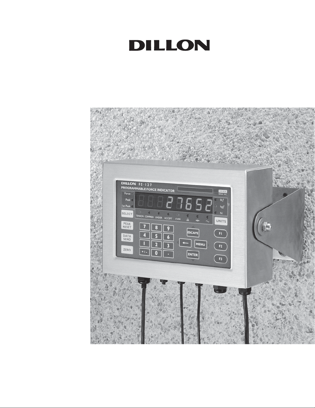
The model FI-127 is a versatile, full-featured indicator housed in a stainless steel
enclosure. Its user interface includes an 8-digit, 7-segment LED display, fourteen
LED annunciators, and 24 keys.
This manual is divided into the following major sections:
• Introduction
• Operating Modes
• Front Panel
• Error Messages
• Using Your FI-127
• Using the User Menu
• Using the Service Menu
• Reset Menu/Master Clear
• Adding and Calibrating a Loadcell
• Step by Step Instructions
• Freeze Force Function
• Data Capture
Operating Modes
There are three modes of operation for the FI-127—Display mode, User Menu
mode and Service Menu mode.
In Display mode you perform all normal force measurement operations.
The User and Service menus give you access to testing modes, configuration of
your system, database and system information. This manual explains how to use
these different modes of operation.
5
Page 6
Front Panel
The FI-127's front panel consists of 24 keys and fourteen annunciators.
Keys
Standard Instrument Keys
Function Keys
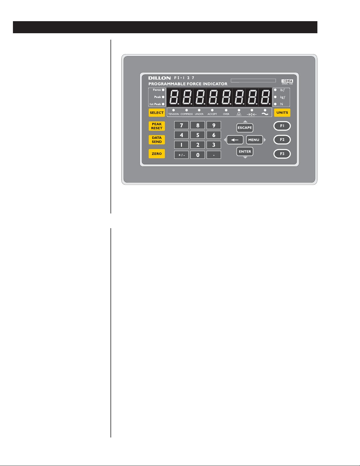
Figure 1
FI-127 Front Panel
The FI-127's keys are divided into four primary groups:
Standard Instrument Keys These yellow keys are common to a majority of
applications and include SELECT, PEAK RESET, DATA SEND, ZERO, and UNITS.
The SELECT and UNITS keys are placed next to the annunciators they affect.
SELECT Use to switch between force, peak ad first peak display modes.
SELECT can also be used to accept a current selection and
return to weigh mode from within any menu.
PEAK RESET Use to reset all peak and first peak values. This key may also be
used to capture the current measurement as an entered value
during data entry.
DATA SEND Use to initiate one or more serial outputs.
ZERO Zeros the scale in the display mode. Also clears values in
numeric entry.
UNITS Switches the units of measure in the display mode. Up to three
units of measure are selectable.
Function Keys These oval keys along the right side of the display face are
configurable and are labeled F1, F2, and F3. The default configurations for these
keys are:
F1 Allows load cell selection
F2 Allows entry of ID number
F3 Allows access to cutoff registers.
6
Page 7

Keypad Keys
Keypad Keys These are the twelve square keys which support numeric entry.
The keyboard keys are labelled 0-9, plus/minus (+/-), and decimal point (.) and are
located near the center of the display face.
+/- This key is used to change the sign of a numeric entry, enter a dash in ID
entry, and insert when editing lists. This key also initiates numeric entry,
except in display mode where it serves to toggle between tension and
compression for bidirectional cells. Toggling between tension and compression resets peak, first peak and break detect; unfreezes the force display; and
halts data capture.
Directional Keys
Directional Keys The directional keys are used to navigate through the FI-127's
menus. These keys are labeled ESCAPE (up), ENTER (down),
MENU (right) and are positioned in a compass-like cluster on the display face.
These directional keys are denoted by the small transparent arrows located next
to them. ESCAPE, ENTER, and
ESCAPE Exits a menu parameter without saving any changes. This key moves
up within a menu. In display mode, ESCAPE "unfreezes" the force
display.
ENTER Used to end digit entry, accept a change made, or select an item
from a function list. ENTER moves down within a menu. When in
display mode, ENTER "unfreezes" the force display.
ÅÅ
Å Backspaces (deletes the last digit or punctuation mark entered)
ÅÅ
while in numeric entry and moves left within a menu.
MENU Accesses user menus and moves right within a menu.
←←
← also support numeric entry.
←←
←←
← (left), and
←←
Annunciators
The FI-127 has fourteen annunciators.
Force Illuminates when indicator is in force display mode.
Peak Illuminates when indicator is in peak display mode.
1st Peak Illuminates when indicator is in first peak display mode.
lbf, kgf, N Illuminates the active unit of measure in weighing mode.
Data Send: Illuminates when the indicator is transmitting data.
Does not illuminate when a host connection is communicating
with the indicator or with continuous send.
Zero: Illuminates when the scale is within the configured center
of zero.
Motion: Illuminates when the scale detects motion (within
configured motion window).
Under, Accept, Over Specific application annunciators.
Tension Indicates the type of force being measured.
Compression Indicates the type of force being measured.
7
Page 8
Error Messages
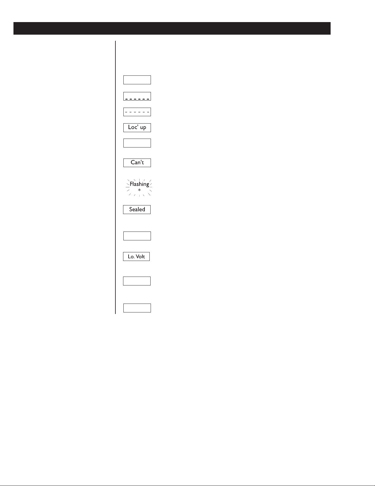
The following are displays you may see if problems occur or if invalid operations
are attempted with your FI-127:
Display Description
O. LoAd
L.C. Error
Auto. 0
Overrange force.
Underrange force.
Recovering from lock-up or out of range condition.
A-D converter is not functioning.
A-D converter subjected to an input signal beyond ±5.00000 mV/V
The unit cannot perform a function. Displayed only while key is held
down.
Corrupted data in the reset menus. See the Service Manual.
(* = RESET, SETUP, or CAL)
Displayed while a key is pressed when attempting to modify a sealed
selection without edit privileges.
Displayed while waiting for a stable, valid weight to use as a zero
reference on power-up.
Displayed when input voltage to excitation regulator drops below
10.5 VDC. Will clear when input voltage rises above 11.5 VDC.
1 Busy
Ouch
Displayed when the ready/busy handshake has exceeded its time out
limit. Default is 2 seconds. This can also apply to optional 2nd and
3rd serial ports.
Displayed when the force applied to the load cell has exceeded the
level considered to be abusive to the load cell.
8
Page 9

Using Your FI-127
Setting Up Your FI-127
Performing a Force
Measurement
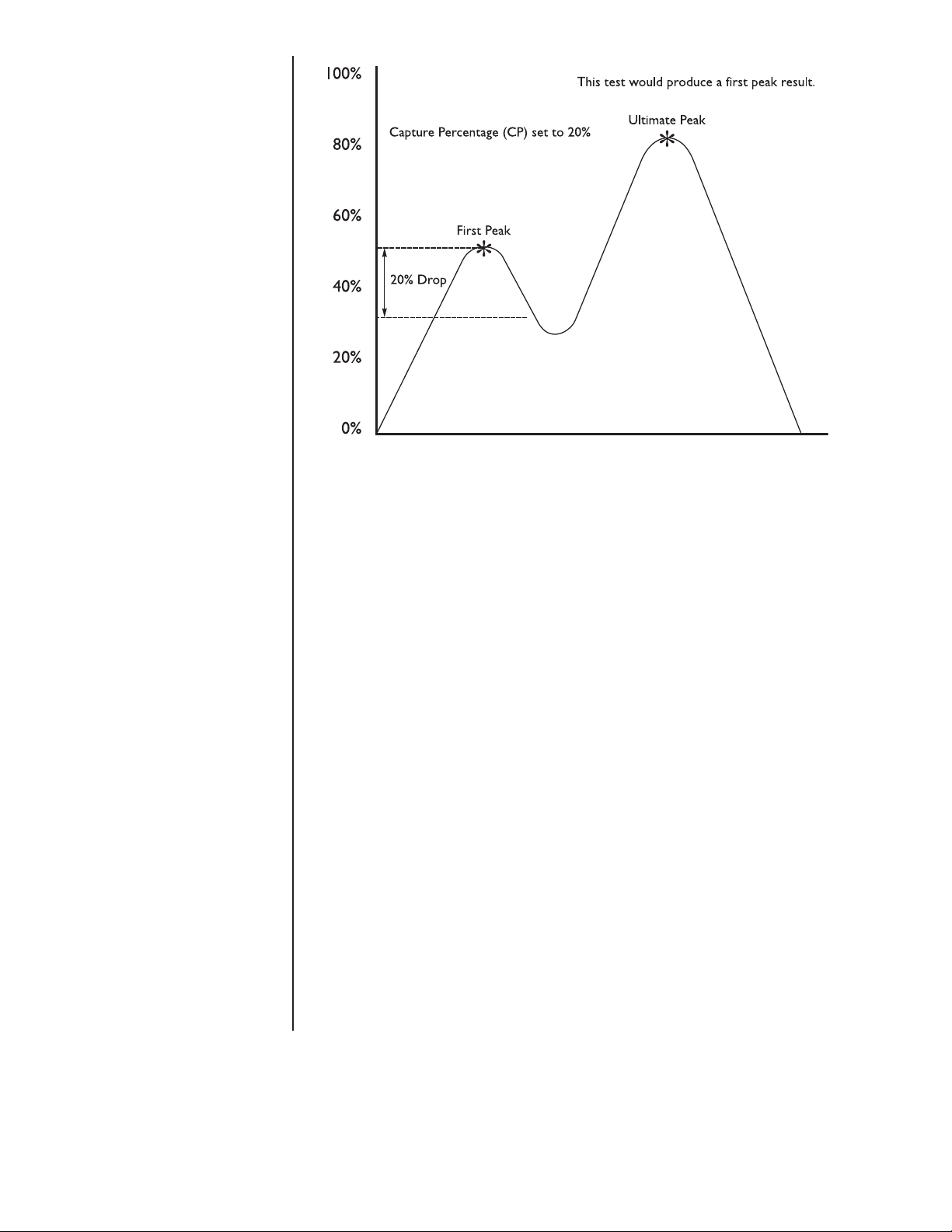
First Peak
First peak is defined as an applied
force, followed by a drop in force of
at least x% of full capacity followed
by an ultimate peak in force. x is
called the capture percentage. You
can set this percentage via the front
panel. Instructions can be found in
the section Using the Service
Menu. See the graphed example in
Figure 2.
Your FI-127 will probably be ready to use when you receive it from your Dillon
distributor. Connect the loadcell to the 7-pin connector on the back of the unit.
Connect your RS-232 communication equipment to the other connector on back
of the FI-127. Power up your peripheral equipment and plug in the FI-127 to an
appropriate grounded power source.
The indicator will power up in Display mode with annunciators lit for your
application. From the factory, the default annunciators which are lit are Force,
Tension and lb F. The center of zero (COZ) annunciator should also be lit. If the
display does not show 0 or the COZ annunciator is not lit, press the ZERO key.
Your unit is now ready for use in your force measurement application. If you want
to add a loadcell, see the section Adding a Loadcell later in this manual.
1. With the indicator powered up,
select the unit of measure you
want to use by pressing the
UNITS key. . . The proper annunciator will light.
2. Press the ZERO key if the display
does not show 0 and apply force
to the loadcell. . . The force will be displayed in the unit
of measure you have chosen. The type
of force, tension or compression, will
be indicated by the annunciators under
the display. The motion annunciator
will be lit while the indicator detects
motion.
3. If you are running a test where
First Peak and Peak readings are
important to you, you can see
those values by pressing the
SELECT key. The value on the
display will correspond to the
annunciated item on the left side
of the display panel. See the First
Peak definition at left.
4. After you have seen the peak
values, you can reset them by
removing the force from the loadcell and pressing the PEAK
RESET key.
5. Repeat steps 2-4 for the other
force measurements you want to
make.
9
Page 10
Full Scale Capacity of Loadcell
First peak illustration
Time➔
Figure 2
Using the Function Keys
F1 Key
The function keys are used for
• F1 Loadcell selection
• F2 ID number entry
• F3 Viewing or entering data in cutoff registers
1. Press F1 key. . . The display shows the current cell
number and a letter showing if the cell
type is F for force or T for torque.
2. Press the ENTER key. . . The capacity of the current cell is
displayed.
3. Press the MENU key. . . The division size for the current cell is
displayed.
4. Press the ENTER key to return to
Display mode or press
the ESCAPE key to return to the
display from step 1.
10
Page 11

F2 Key
1. Press the F2 key. . . The current ID number is displayed.
2. Press any of the following keys to
return to Display mode:
ÅÅ
F2,
Å, MENU, ESCAPE,
ÅÅ
SELECT
or
press a number key to start
entering a new ID number. When
you are finished, press the ENTER
key. . . The new number will become the
active ID number.
F3 Key
Cutoff Register
A cutoff register is a force value you
enter into memory (register) which
the indicator uses to control outputs.
There are 10 cutoff registers in the
FI-127. You can set ten different
force values which the indicator will
use to trigger outputs.
When activated (force on the
loadcell is less than the force in the
cutoff registers), these cutoffs are all
on at the same time. Each cutoff will
deactivate as soon as the force on
the loadcell matches the value in
each cutoff register.
When the force is equal to or
greater than positive register values,
or more negative than negative
register values, the corresponding
output is disabled.
When the force is less than the
positive register values, or less
negative than negative register
values, the corresponding output is
enabled.
The F3 key is used to view and change cutoff registers. You can view cutoff
registers by two methods:
Method A:
1. Press the F3 key. . . 1 xx is displayed. The number 1
stands for cutoff register #1 and xx is
the current value in register 1.
2. Continue pressing F3 or MENU
to scroll forward or
backward through the remaining
cutoff registers.
Method B:
1. If you know which cutoff register
you wish to view, press the
number of that register, then press
F3. That particular cutoff register is
displayed.
To change a cutoff value, display the register you want to change then:
1. Key in a new value with the
numeric keypad. Use the +/- key to
change the sign of the value.
Press the ENTER key to accept
the new value and return to
Display mode
or
press the F3 key to accept the new
value and move to the next register.
ÅÅ
Å to scroll
ÅÅ
2. To deactivate or clear a cutoff
value, set the value to zero.
11
Page 12
Using the User Menu
Use these keys to navigate
through the menus:
ESCAPE =up
ENTER = down
ÅÅ
Å = left
ÅÅ
MENU = right
The FI-127 has two menus—the user menu and the service menu. The service
menu is covered later in this manual. You use it to configure the operation of your
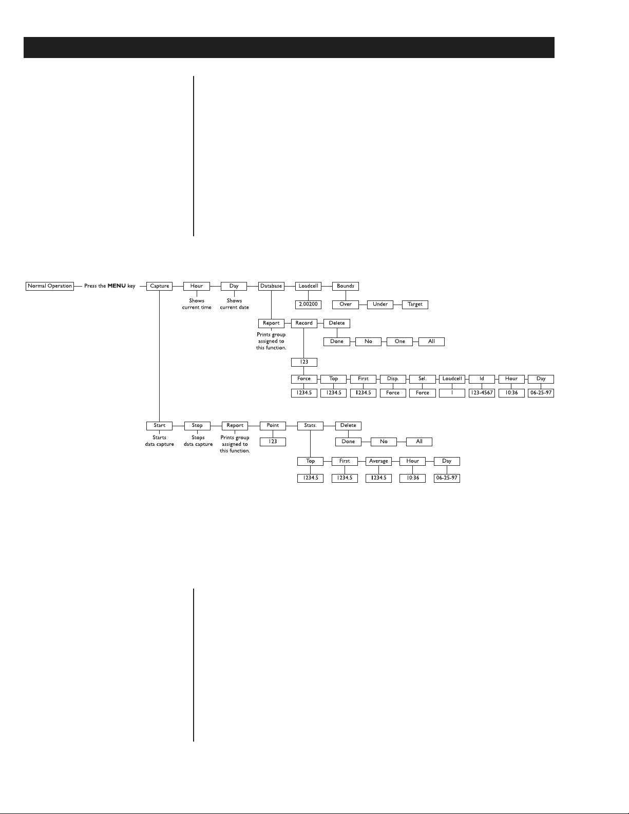
indicator. The user menu, shown in Figure 3, allows you to do the following things:
• Capture and view data points
• Print a report on data points
• View statistics about captured data points
• Delete captured data points
• View the current time and date
• View and delete database records
• See live display of loadcell output in counts or mV/V
• Set Target, Under, and Over values
The User Menu
Capture
This manual assumes that all
functions are enabled. Your indicator
may not show some of the items in
the user menu because your
configuration does not enable them.
See the Using the Service Menu
section to reconfigure your system.
12
Figure 3
User menu
Following are instructions for accessing and using the user menu. Refer to Figure 3
as you go through these instructions.
1. Press the MENU key. . . CAPturE is displayed. This is the first
menu item. Use this to start and stop
capturing data points, view captured
points, see statistics on captured points
and to delete the points.
2. Press the ENTER key. . . StArt or StoP is displayed depending
on if you are currently capturing data
points or not.
Page 13

3. Press the ENTER key to start or
stop capturing data points. . . The indicator will start or stop captur-
ing data points.
4. Press the MENU key to move to
the next menu item. . . rEPOrt is displayed. Use this to print a
report on the data capture information.
5. Press the ENTER key with this
displayed if you want a
preconfigured set of information
to be sent through the serial port.
6. Press the MENU key to move to
the next menu item. . . Point is displayed. Use this to see any
captured data point.
7. Press the ENTER key to view the
current point number. Press
MENU to scroll to other points.
With the point you want displayed,
press the ENTER key to see the
value of that data point. . . The captured point will be displayed as
ÅÅ
Å or
ÅÅ
well as the unit of measure and tension/
compression annunciators.
Remember to use the direction keys
to navigate among the levels and
choices in the menu structure.
Press SELECT to accept the
current selection and return to the
Display mode from anywhere in the
menus.
8. Press the MENU key to move to
the next menu item. . . StAtS. is displayed. Under this item you
can see statistics on the captured data
points.
9. Press ENTER to see the first item
in the list of statistics. Press the
or MENU to move to other stat.
items and press ENTER to see the
value for the displayed statistic.
Following are the statistics and
what they show you:
Top Peak value for the currently captured points.
First Shows the first peak value for the currently captured points.
Average Shows the mean value of the currently captured points. Does
not include those points which are below the data capture
threshold set in the Ave. Over parameter of the setup menu.
See the Service Manual.
Hour Time at which the data was captured.
ÅÅ
Å
ÅÅ
Day Date on which the data was captured.
13
Page 14

Use these keys to navigate
through the menus:
ESCAPE =up
ENTER = down
ÅÅ
Å = left
ÅÅ
MENU = right
10. After viewing the statistics, press
the ESCAPE key until StAtS. is
displayed, then press MENU to
see the next menu item. . . dELEtE is displayed. Use this to delete
all captured data points.
11. Press the ENTER key. . . donE is displayed if there are no data
point to delete. All is displayed if there
are data points to delete.
12. If there are data points to delete
and you want to delete them, press
ENTER while All is displayed. . . The data points are deleted from
memory and donE is displayed.
Hour
13. Press ESCAPE twice to return to
the CAPturE display. Press MENU
to move to the next user menu
item. . . Hour is displayed.
14. Press ENTER to see the currently
set time. . . Time is displayed as HH:MM:SS (24
hour clock) or HH:MM:SS AM (12
hour clock). You may toggle between
the two formats by pressing the
UNITS key.
15. Press ENTER or ESCAPE to
leave the time and format
unchanged or enter a new time
using the numeric keys.
16. After changes have been made to
the time, press the ENTER key to
accept them and start the clock. . . Display shows Hour.
14
Day
17. Press the MENU key to go to the
next menu item. . . dAY is displayed.
18. Press ENTER to see the currently
set date. . . The date is displayed as MM/DD/YY.
19. Press ENTER to accept this date
or key in a new date and press
ENTER to accept it. . . dAY is displayed.
Page 15

Database
20. Press the MENU key to go to the
next menu item. . . dAtAbASE is displayed. Under this
menu item you can send a
preconfigured report of database items
to a serial port, look at individual
records in the database and delete one
or all of the records.
21. Press the ENTER key. . . rEPOrt is displayed. Use this to send a
report to a serial port. The information
sent depends on the configuration of
your system. See the Service Manual for
instructions.
22. Press the ENTER key to send the
database information to the serial
port. . . The print annunciator will light then the
display will show dAtAbASE again.
23. Press ENTER then MENU to go
to the next menu item under
dAtAbASE. . . rEcord is displayed.
24. Press the ENTER key to access
the current record. . . A record number is displayed.
25. You can view this record's data by
pressing the ENTER key
or
you can access other record
numbers by pressing the
MENU key, then press the
ENTER key. . . The first item in the database record is
26. Use the
through the list of items, then
press the ENTER key to view the
value for each item,
ÅÅ
Å or MENU key to scroll
ÅÅ
ÅÅ
Å or
ÅÅ
displayed. What this item is depends on
the configuration of your database.
15
Page 16

Use these keys to navigate
through the menus:
ESCAPE =up
ENTER = down
ÅÅ
Å = left
ÅÅ
MENU = right
Below is a full list of items in default order:
Force A stored force measurement. Displayed with unit of measure and
tension/compression annunciators.
Top A stored peak value. Displayed with unit of measure and tension/
compression annunciators.
First A stored first peak value. Displayed with unit of measure and
tension/compression annunciators.
Disp. A stored measurement. May be Force, Top or First depending on
configuration. Press the ENTER key again to see the value. Displayed as F 1234.5 if the stored value is a frozen force. Displayed
with unit of measure and tension/compression annunciators.
Sel. A stored measurement. May be Force, Top or First depending on
configuration. Press the ENTER key again to see the value. Displayed with unit of measure and tension/compression annunciators.
Loadcell A stored loadcell number.
Id A stored ID number.
Hour Time the record was stored.
Loadcell
Day Date the record was stored.
27. Press ESCAPE until rEcord is
displayed, then press the MENU
key to move to the next item in
the database submenu. . . dELEtE is displayed. Use the items
under this to delete one or all the
records.
28, If you choose to delete one record
you can scroll through the records
using the
press the ENTER key to delete
that one record. . . dELEtE is displayed.
29. With dELEtE displayed, press the
ESCAPE key. . . dATAbASE is displayed.
30. Press the MENU key to move to
the next user menu item. . . LOAdCELL is displayed.
ÅÅ
Å or MENU keys then
ÅÅ
16
31. Press the ENTER key to see a live
display of loadcell output in either
mV/V or counts. Toggle between
the two views using the UNITS
key.
Page 17

Bounds
32. Press the ESCAPE key to return
to the LOAdCELL display, then
press MENU to move to the last
user menu item. . . boundS is displayed. Use this item to
set target, over and under values. See
example at left.
Target, Over, Under Example
Target value = 350
Under value = -10
Over value = 20
With these settings the ACCEPT
annunciator will be lit when force is
340 to 370. The UNDER annunciator will be lit when force is less than
340. The OVER annunciator will be
lit when force is greater than 370.
33. Press the ENTER key. . . OVEr is displayed.
34. Press ENTER to see the current
value. Key in a positive value then
press ENTER to accept it. . . OVEr is displayed.
35. Press MENU to display UndEr.
Press ENTER to see the current
value. Key in a negative value then
press ENTER to accept it. . . UndEr is displayed.
36. Press MENU to display tArGEt.
Press ENTER to see the current
value. Key in a value then press
ENTER to accept it. . . tArGEt is displayed.
37. This is the last item in the user
menu. Press ESCAPE repeatedly
or SELECT to return to
Display mode.
17
Page 18
Using the Service Menu
Be sure to key in the password '127'
before pressing and holding the
ESCAPE key if you want to
change items in the service menu,
otherwise you will only be able to
view them.
You use the service menu to see information about your indicator, to test its
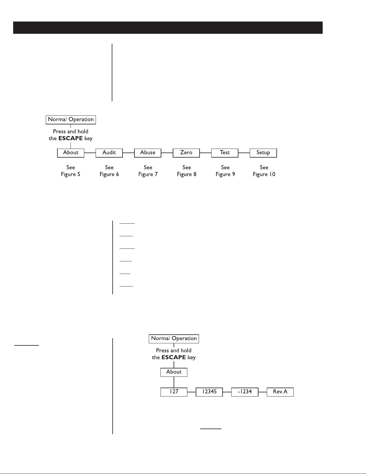
various functions and to configure how you want the system to work. Figures 4
through 19 show the service menu structure in the FI-127. Following each figure
are explanations for each of the service menu items. Use the same methods to get
around in the menu structure as you used in Using The User Menu section of this
manual. To edit items in this menu you must key in '127' before pressing
and holding the ESCAPE key.
Figure 4
Top level of the Service menu
About Menu Information about the software
About Menu
Audit Menu Audit counters for calibration and configuration
Abuse Menu Loadcell overload counters
Zero Menu Zero balance information and reset
Test Menu For testing the hardware of the indicator
Setup Menu For configuration of the indicator
18
Figure 5
About menu
Page 19
Audit Menu
These are the items listed in the
127 The unit designation.
12345 Parent part number of the software.
-1234 The dash portion of the software part number.
Rev. A The revision level of the software.
About menu:
Figure 6
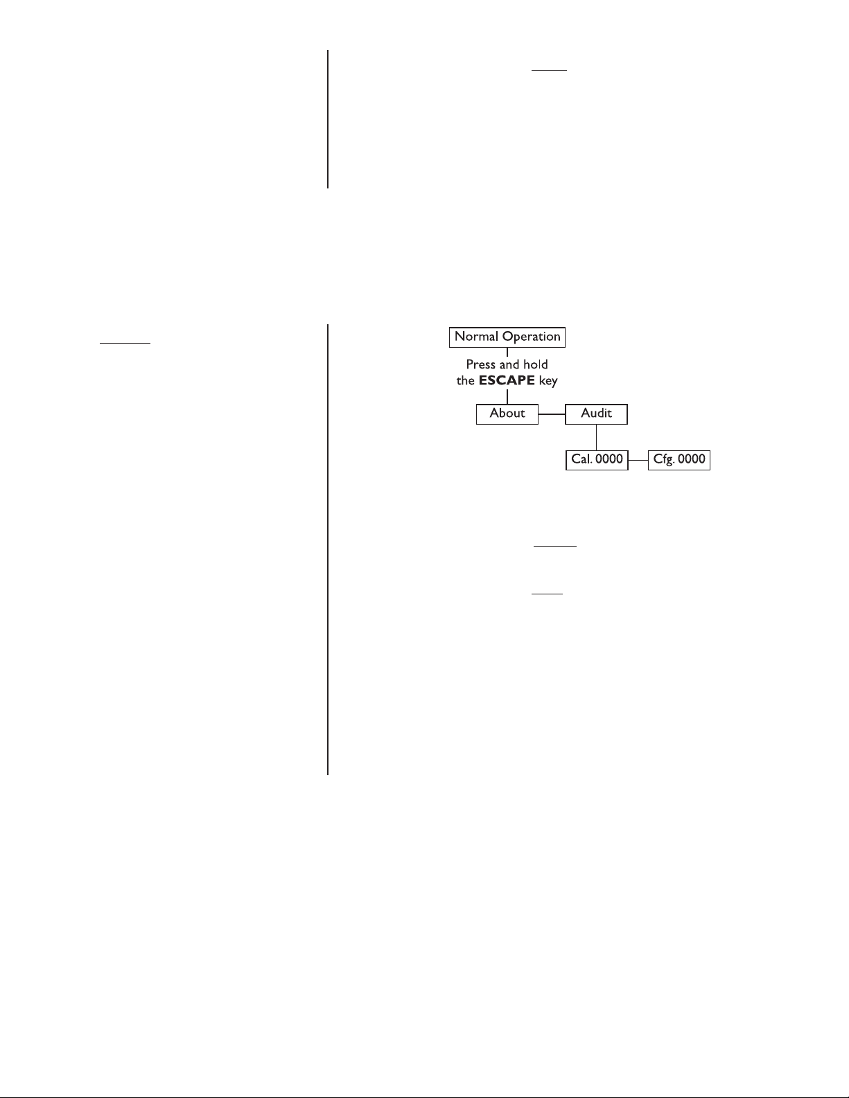
Audit menu
These are the items listed in the Audit menu:
Cal. 0000 This is an example of how the calibration audit trail counter will
appear. The actual value will be between 0000 and 9999. It is
nonresettable and may not be edited.
Cfg. 0000 This is an example of how the configuration audit trail counter
will appear. The actual value will be between 0000 and 9999. It is
nonresettable and may not be edited. The counter is
incremented each time a metrological item is modified in the
setup menus and saved and so may be used as a control audit.
19
Page 20
Abuse Menu
Be sure to key in the password '127'
before pressing and holding the
ESCAPE key if you want to
change items in the service menu,
otherwise you will only be able to
view them.
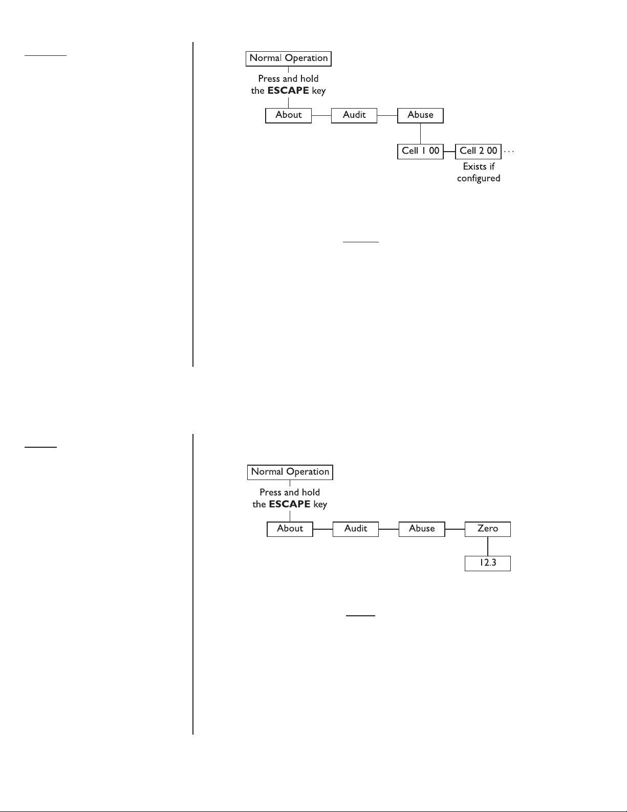
Figure 7
Abuse menu
Cell 1 00 This is an example of how a loadcell overload counter appears.
Use the
have. The counter shows up to 99 overloads. An overload is
defined as an applied force beyond the threshold configured
under Abused in the loadcell configuration section of the
service menu. The overload counter can only be reset at the
factory.
ÅÅ
Å or MENU keys to view other loadcells you may
ÅÅ
Zero Menu
This menu provides access to zero balance information and reset.
Figure 8
Zero menu
12.3 This is an example of the offset between the current zero
balance and the zero balance value established in calibration.
Displayed offset = Calibration zero - Current zero
When you press the ZERO key the current balance is reset to
calibration zero and resets the peak and 1st peak. The force
display is also unfrozen.
20
Page 21

Test Menu
The test menu, shown below, gives you access to diagnostic tests.
Figure 9
Test menu
These are the items listed in the Test menu from left to right:
Display Press ENTER to start and stop a continuous display test. With
the test stopped press the
or forward one step at a time. Press ENTER again to resume
the automatic test or press ESCAPE to stop the test and
return to diSPLAy.
Buttons This provides a test of the keypad. The name of the key that is
pressed appears on the display. If no key is pressed, nOnE is
displayed. Press MENU to return to buttonS.
A to D Press this key to see the current A to D value. The displayed
resolution is 1 part in 20,000 per mV/V. This test exists so that
the offset and gain of the electronics can be checked. The offset
is initially set to the nominal offset of the electronics, but you can
press the ZERO key to establish the actual offset, allowing the
gain to be evaluated.
ÅÅ
Å or MENU key to move backward
ÅÅ
21
Page 22

With motors connected to external
circuits, this is a good way to test
your hardware.
☞
Loadcell With LOAdCELL displayed, press the ENTER key to see a live
display of the current counts coming from the A-D converter.
400400 is an example of how this might appear. Press the
UNITS key to toggle between the counts display mode and the
mV/V display, which appears in this format: 2.00200. This stands
for 2.002 mV/V. The decimal indicates you are looking at mV/V
and not current counts.
Serial This item accesses the internal port serial tests. With SEriAL
displayed, press the ENTER key. Port 1 is displayed. This is
always the internal serial port. When the optional serial boards
are installed in the same stack, port two is always on the bottom.
When installed in different stacks (side by side), port two is
always closest to the power supply. Press the
to select the port you wish to test.
Ready/
Busy With the port you want to test displayed, press the ENTER
key. rEAdy or bUSy is displayed telling you if the hardware
input line is ready or busy. This is useful in tracking down serial
output problems.
Loop/
No Loop Press the MENU key to see the Loop - No Loop test. Connect
the transmit line to the receive line at some point in the cabling.
The FI-127 checks if it receives the same characters that it
transmits. If it can, LOOP is displayed. If it cannot, no LOOP is
displayed. This is useful in isolating serial output problems to the
FI-127, cable, or connected device by looping back at the
corresponding points.
Outputs This test allows you to check the operation of the onboard and
optional outputs. The onboard outputs are copies of the first
three outputs on the optional I/O board when it is installed.
ÅÅ
Å or MENU key
ÅÅ
To exit back to Display mode, press
the SELECT key and save changes
as needed by pressing ENTER with
SAVE? displayed.
22
Sequence This is the first item in the Outputs submenu. Press the ENTER
key to test the outputs. Each output is turned on and off
sequentially. The display will show Out. nn. The nn being the
number of the output being tested. The outputs will sequence
every half second. Press the ENTER or ESCAPE key to end
the test and return to the SEqUEnCE display.
Out 1-3 (or 1-16 with optional boards)
This is the second item in the Outputs submenu. This allows you
to activate or deactivate any of the outputs 1-3 (1-16 if the
optional boards are installed). Press the ENTER key to see the
display of the outputs status.
The screen has 0s and 1s displayed in this format: 00.010000. In
this example, output #4 is active. The zeros and ones represent
the status of each output. A 1 means it is activated and a 0
means it is deactivated. The left digit is output #1 or #9.
To change the status of an output, press the
to move the decimal point to the right of the output you want to
change. Press the ENTER key to toggle the output from one
status to the other.
ÅÅ
Å or MENU key
ÅÅ
Page 23

This allows you to test your remote
push button switches (ie. remote
zero, print, etc.)
☞
Press the ESCAPE key to exit the test. The outputs remain as
selected until you exit the Test menu. Returning to Display
mode returns the control of the outputs to the cutoff values.
Inputs This test allows you to check the operation of the onboard and
optional inputs. Press the ENTER key to access the submenu.
Standard This submenu item lets you check the status of the onboard
inputs. In this example, 1000100, inputs #1 and #5 are active.
The inputs are ordered 1-8 from left to right. A 1 means
activated and a 0 means deactivated.
As you view the inputs, #8 is actually a flag that is dependent on
the states of inputs 6 and 7. Input 6 resets flag #8 to a false 0.
Input 7 sets flag #8 to a true 1. Input 8 does not terminate at a
connector.
Option This menu item is available only if the option board is installed. It
works the same way as the Standard example above.
Voltages The submenu under VoltAgES lets you see the power supply
voltages. The voltage readings are updated 2 times per second.
13 volts This test displays the unregulated weight sensor excitation
power supply voltage. If the voltage drops below 10.5 the display
will show Lo. Volt. The error condition will not clear until
voltage reaches 11.5.
- 5 volts This test displays the -5 volt excitation voltage.
10 volts This test displays the unregulated 5 volt logic supply voltage.
24 volts This test display shows the relay supply voltage. If this voltage
drops too far it may not be possible to activate certain relays.
Nominal level for this power supply voltage is 22.8.
23
Page 24

Setup Menu
Be sure to key in the password '127'
before pressing and holding the
ESCAPE key if you want to
change items in the service menu,
otherwise you will only be able to
view them.
The setup menu allows you to configure your indicator to your specific application. Each item in this menu is described in the order presented in Figure 10.
Figure 10
Setup menu
Units submenu
The first submenu under Setup is Units. This submenu lets you select what unit of
measure will be assigned to the three annunciators on the front panel.
24
Figure 11
Units submenu
Page 25

Units
Unit 1 The unit of measure you choose for this item will be assigned to
the annunciator labeled “lb f” on the front panel. You can also
choose a length unit of measure for torque loadcells. Following is
the list of units of measure:
* = default value
To exit back to Display mode, press
the SELECT key and save changes
as needed by pressing ENTER or
SELECT with SAVE? displayed.
To exit without saving changes, press
ÅÅ
Å or MENU until No Save
ÅÅ
appears then press ENTER or
SELECT.
Pounds F* = pounds force
1000g F = kilograms force
N = Newtons
1000 N = 1000 Newtons
g F = grams force
OZ F = ounces force
Ton F = tons force
Tonne F = tonnes (metric tons) force
Other = Allows you to define a custom unit of force. Choose
what unit of force you want it based on, a multiplier upon which
the custom unit is based and an ASCII label to be used in serial
output. See the example at the bottom of this page.
None = no unit of measure is assigned.
Following is the list of length units of measure you can choose:
foot* = foot
inch = inch
m = meter
cm = centimeter
other = Allows you to define a custom length unit. Choose what
unit of length you want it based on, a multiplier upon which the
custom unit is based and an ASCII label to be used in serial
output.
Unit 2 The unit of measure you choose for this item will be assigned to
the annunciator labeled “kg f” on the front panel. You have the
same choices as shown in Unit 1 above. 1000g F is the default
setting.
Unit 3 The unit of measure you choose for this item will be assigned to
the annunciator labeled “N” on the front panel. You have the
same choices as shown in Unit 1 above. N is the default setting.
Custom Unit Example:
If you want a unit of measure called PLUTOs that is equal to 3.5 pounds of
force you need to enter the ASCII codes for P, L, U, T, and O. (See Appendix A). Enter pounds as the unit of measure the custom unit is based on and
enter 3.5 as the multiplier so that 1 PLUTO will equal 3.5 pounds.
25
Page 26

Loadcells submenu
The next Setup submenu is Loadcells. Use this menu, shown in Figure 12 to
linearize and configure each loadcell in your system.
Cell 1 This is the first loadcell in a list of loadcells. Cell 2, Cell 3, etc. are
available by pressing the MENU key if they are configured. To
add loadcells to the system, press the +/- key while End is
displayed. To delete the last loadcell from the list, press ZERO
while that Cell # is displayed. The FI-127 supports up to six
loadcells.
Below are the descriptions of the items available under each
configured loadcell.
Cell Type Choose which type of loadcell you are using: Force or Torque.
Polarity Select the direction of positive measurement:
Regular - selects tension for force and clockwise for torque.
Counter - selects compression for force and counter clockwise
(CCW) for torque.
Bi-dir. - specifies that the loadcell is bidirectional and is used for
measuring force in both tension and compression, or torque in
both CW and CCW directions. This selection enables the +/- key
to change measurement direction while in the display mode.
Calibration is part of the Linear-
ize process. See the section
titled Adding and Calibrating a
Loadcell for more detailed
instructions on calibrating your
loadcell.
☞
Linearize
Points Use this submenu to view, edit, add, or delete calibration
points in a list. You may have 2-10 points per loadcell with
a maximum of 35 points among all six available cells.
A 0
A 5000
Examples of the two default calibration points. The
indicator will automatically order the list by increasing
count values. The first point will show A 0. The A stands
for Applied load and the 0 for zero force. Access other
existing points by using the
The FI-127 comes from the factory with two calibration
points: 0 and 5000 lbs f. (These force values may differ
depending on your unit of measure.)
Cal.
Counts
Points may be calibrated in two ways: 1) by standard force
calibration or 2) by entering count values. Counts are
calibrated to 5000 lbf at 1 mV/V signal from the factory.
Existing points may be reviewed and modified via the
keyboard.
Delete
You can delete a calibration point using this item.
ÅÅ
Å or MENU key.
ÅÅ
26
Deadload Lets you view the count value for the current deadload.
Press the UNITS key to change the display to mV/V.
Display Shows the weight display without having to exit the menus.
An example of what is shown—d 5000. The d indicates a
live display of weight and reminds you that the unit is in
calibration. The value you see depends on the selected unit
of measure, the calibration and the weight applied. The
UNITS key works in this mode
.
Page 27

Figure 12
Loadcell submenu
Use these keys to navigate
through the menus:
ESCAPE =up
ENTER = down
←←
← = left
←←
MENU = right
27
Page 28

Printing the calibration values will
allow both a record of your calibration and a means of restoring a
calibration if the indicator fails or is
damaged.
Reset Use this item to reset the calibration points to factory
default values. If you choose yES the values are set to 0
lbs f at 0 mV/V and 5000 lbs f at 1 mV/V.
Print Lets you print the calibration values for a selected loadcell.
See note at left. Choose from No or Yes. If you choose
Yes, the information is output to port 1. Below is an
example of the output format:
07-04-97 10:36 AM
Loadcell 1 T
lbf mV/V
-------- --------
-20000 -0.20055
0 0.00101
10000 0.10203
20000 0.20301
30000 0.30512
40000 0.40333
100000 1.01234
Serial No. _______
If you change capacity or division
size in any unit of measure, this
automatically changes all the other
enabled units of measure as well.
If you want leading zeroes in your
printouts or broadcast and autosend
information, key in leading zeroes
when setting division size.
The T after Loadcell stands for tension. This string
corresponds to the Cell Type.
Config. This submenu contains force measurement related parameters.
Capacity Use this to see or edit the capacity. The UNITS key
works during this display. 5000 lb f is the default value.
Division This selection allows you to view and edit the division size
of the enabled units of measure. You can enter any
division size. The indicator will use the closest division size
for each enabled unit of measure.
You can view the division in other units of measure by
pressing the UNITS key. The number is stored in the
resolution you enter but is displayed in the closest valid
division size. Any additional resolution is used in calculating division size in the other units of measure.
Zero Use this menu item to set zero related options. Zero
range is specified as a percent of capacity referenced from
the deadload. There are two items in the submenu:
-Range and Range.
-Range - Use this to set the negative range (below
reference zero) within which the unit may be zeroed. 2%
is the default value.
28
Range - Use this to set the positive range (above reference zero) within which the unit may be zeroed. 2% is the
default value.
Page 29

Bust Use this to enter a break percentage. Break percentage is
the drop in force which the indicator will interpret as a
break detection. This is entered as percentage of full
capacity. 10% is the default value. The output signal is
asserted when a break is detected and switches to the
inactive state whenever you perform a zero or peak reset.
Capture Use this to enter a capture percentage. Capture percent-
age is drop in force occurring before a rebound in force to
an ultimate peak of force. This capture percentage is given
as a percentage of full capacity. See Figure 2 for an
illustration.
Stable Use this menu item to set the motion detection param-
eters. There are three items in the submenu: Range,
Delay and Display.
Range Use this to specify the number of ±divisions for
the motion window. Default is 1.0 division.
Delay Use this to specify the number of seconds
during which the weight must be within range (described
above) before a no-motion condition is displayed. Default
value is 0.4 seconds.
Display Choose ON to if you want the display on while
the indicator senses scale motion. Choose OFF to blank
the display while there is scale motion. Default is ON.
Update Use this to set the display update rate from these choices:
1 One update per second.
2 Two updates per second
5 Five updates per second
10 Ten updates per second.
29
Page 30

Average Use this to configure the number of intervals to average
for each force display. This can be entered in one of two
methods: x disp. or x a-ds. Press the UNITS key to
switch back and forth between the two choices.
The suggested method of setting the average is by picking
a value for x disp. Doing this insures that a multiple of the
display rate is always being averaged. This results in a
steadier weight display.
Use x a-ds if you need an exact number of A-D conversions for your particular situation.
Changing the update rate changes
the x disp. or x a-ds value based on
the new update rate.
Harmonizer® filter is used only if the
average value will not filter out the
vibration by itself. See Tips on
setting up and using the
Harmonizer filtering in Appendix
C.
Throughout the calibration process
values will change as you press the
UNITS key to change the unit of
measure.
☞
x disp. - 1 disp. is the default display when you access this
item. x is the number of display interval(s) over which the
data is internally averaged prior to being displayed.
The number of A-Ds averaged is based on the display
update rate you set under the Update menu item. Default
is 1 disp.
x a-ds - x is the number of a-d conversions to average for
each display.
The A-D weight conversion happens 60 times per second
in this indicator. Average is the number of conversions
you want to average for the weight that is displayed.
Default is 12 a-ds when Update is at default of 5 and x
disp. is at default value of 1.
Filter Use this menu item to configure the Harmonizer filter
settings. Constant and Threshld are the two items you
can configure in this submenu.
Constant - This number represents the amount of
filtering. Choose a setting between 1 and 10. Choose 1 for
the least amount of filtering but the fastest response.
Choose 10 for the most filtering but the slowest response. Choose Off to disable the Harmonizer functions
and default to the lowest filtering.
Threshld - This is the window, in the current unit of
measure, within which weight changes are altered according to the constant. 0.0 is the default value. You should set
the threshold value between 130 and 150% of the total
weight oscillations that need to be suppressed. If weight
changes are +20 lbs and -10 lbs, set this value to 130 to
150% of 30 lbs.
30
Page 31

When using overload or over
capacity alone, set the other menu
item to its maximum value to disable
any conflicts.
Over This submenu lets you setup the overload and capacity
setting which cause the O. load error message.
Overload - This value is expressed as a percent of
capacity referenced from the deadload determined by
calibration. Overload is restricted to 200% or lower. 105%
is the default value.
Over Cap. - This value expressed as a number of divisions
over the capacity referenced from the zero value. A value
of 9 satisfies UK requirements. Configurable from 0 to
999999 divisions. Default is 9 divisions.
Abuse Use this to set the percent of capacity at which an abuse
count will be incremented.
Clone Use this to initialize a the currently selected loadcell with
the same values of another loadcell. Select the number
loadcell you want to clone. If an invalid value for a loadcell
is selected, Error is displayed.
31
Page 32

Options submenu
The next Setup menu item is Options. Use this to configure the way your FI-127
works. Below is the entire menu structure located under this item. See the
following pages for descriptions of these menu items.
32
Figure 13
Options submenu
Page 33

33
Page 34

Buttons Use this to enable or disable the following front panel keys:
Select - Choose Yes or No to enable or disable the SELECT
key.
Units - Choose Yes or No to enable or disable the UNITS
key.
Reset - Choose Yes or No to enable or disable the PEAK
RESET key.
Send - You have two items to configure in this submenu.
PB Send - Use this to determine which layouts are sent
to which ports for pushbutton data send. You
can choose a Group number to send a
preconfigured layout, disable the pushbutton
data send, or save the information to the
database rather than outputting to the serial
port. If you choose the Save option and the
database is full, the display will show Full
when you press the DATA SEND key.
n Send - Use this to enable or disable the ability to key
in a group number then press the DATA
SEND key to send that group data to a serial
port.
Zero - Choose Yes or No to enable or disable the ZERO key.
Menu - Choose Yes or No to enable or disable the MENU key.
F1 - Choose Yes or No to enable or disable the F1 key.
F2 - Choose Yes or No to enable or disable the F2 key.
F3 - Choose Yes or No to enable or disable the F3 key.
Display The Display submenu allows you to customize the order in
which the FI-127 cycles through its weight display modes and
units of measure.
Select Customize the list of weight display modes here. The default list
is: ForceÆTopÆPeak. Repeatedly pressing SELECT while in
the Display mode will cycle through the list in that order. You
may customize the list by inserting and/or deleting items in the
list. The list can contain a maximum of four items.
To add an item: Determine where in the list you wish to insert
an item. Display the item which will immediately follow the one
you are inserting. Press +/-. The ACCEPT annunciator illuminates. Cycle through the options by pressing the
keys until the item you wish to insert is displayed, then press
ENTER. That item is now included in the list.
To delete an item: With that item displayed, press ZERO. That
item is deleted from the list.
Units Customize the list of units of measure here. The default list is:
Unit 1ÆUnit 2ÆUnit 3. Repeatedly pressing UNITS while
displaying a weight in the weight display mode will cycle through
the list in that order. You may customize the list by inserting
and/or deleting items in the list. The list can contain a maximum
of four items.
ÅÅ
Å or MENU
ÅÅ
34
Page 35

To add an item: Determine where in the list you wish to insert
an item. Display the item which will immediately follow the one
you are inserting. Press +/-. The ACCEPT annunciator illuminates. Cycle through the options by pressing the
keys until the item you wish to insert is displayed, then press
ENTER. That item is now included in the list.
To delete an item: With that item displayed, press ZERO. That
item is deleted from the list.
Define The Define submenu allows you to customize printouts, build
ASCII strings, create groups, enable continuous send, assign input
characters to specific actions for each port, enable database
reports, define database records, and configure data capture.
ASCII Under this menu item are Labels and Strings. Following
the explanation of these two items are instructions for
customizing the labels and strings.
Labels are short ASCII strings predefined at the factory.
When information is sent to a serial port and the layout
calls for one of the preset labels, the associated ASCII
string is sent. Following is a list of the label names and the
character called out by the associated ASCII string:
ÅÅ
Å or MENU
ÅÅ
Force = F
Top = P (for Peak)
First = I (for Initial)
Tension = T
'Press = C (for Compression)
C.W. = CW (for Clockwise)
C.C.W. = CCW (for Counter ClockWise)
Id = ID
Strings are groups of ASCII characters. You configure the
indicator to call for these strings in the Layout portion of
the menu. There are five predefined strings and ten other
strings you can modify to suit your needs. The five default
strings are:
Ascii 1: Dillon FI-127<cr><lf><End>
Ascii 2: Loadcell <End>
Ascii 3: Peak: <End>
Ascii 4: 1st Peak: <End>
Ascii 5: Average: <End>
35
Page 36

Instructions for working with strings:
An ASCII character is any number between 0 and 255,
inclusive. See Appendix A for a complete list of ASCII
characters used with the FI-127. To repeat any ASCII
character without entering it multiple times, enter the
number then a decimal, then the number of repetitions
you want. For example, an entry of 32.5 specifies that a
space character is to be transmitted five times. If no
decimal is entered, the indicator will send one character.
To insert a character at the end of the string, just press
ENTER while the indicator displays End. To insert a
character before the current character, press the +/- key.
To move back and forth along the string press the
MENU keys. To delete the current character press
ZERO.
Layouts The FI-127 has 14 default print layouts (max. 15) (see
Appendix B: Default Layouts and Examples). The display
shows LAy. nn, with nn being the identifying number of
that layout.
Each layout consists of one or more of the print items in
Table 1 below. Some items have a selectable variable. To
see this variable, press the ENTER key twice while the
item is displayed, key in a value or press the
keys to scroll through a list. Press ENTER to accept the
variable.
ÅÅ
Å or
ÅÅ
ÅÅ
Å or MENU
ÅÅ
* - denotes items that require
detailed information. For example: if
“LABEL” is inserted within a layout,
you must specify the label to be
printed; if “SP” is inserted, you must
specify the number of spaces to be
transmitted.
See the section Step by Step Instructions for some extra
help.
Table 1: Layout Print Items
*ASCII Select an ASCII string number defined in the ASCII menu.
*Ch. Outputs an ASCII character you enter.
*Spaces Displayed as nn SP where nn is the number of spaces to be
transmitted. (0 through 255)
*Crs Displayed as nn Cr. where nn is the number of carriage
returns transmitted.
*LFS Displayed as nn LF where nn is the number of line feeds to be
transmitted.
FF Transmits a form feed control character.
Force Transmits the Force value.
Top Transmits the peak force.
First Transmits the 1st peak value.
Display Transmits the currently displayed force (force, peak, 1st peak,
frozen force). This means that if a frozen force is displayed,
that is what will be transmitted.
36
Selected Transmits currently selected display. This means that if you
have Force selected but a frozen force is displayed, the live
force will be transmitted.
Page 37

* - denotes items that require
detailed information. For example: if
“LABEL” is inserted within a layout,
you must specify the label to be
printed; if “SP” is inserted, you must
specify the number of spaces to be
transmitted.
Hour Transmits time in 12 hour or 24 hour format, depending on
current setting.
Day Transmits the date in mm/dd/yy format.
Status Transmits the current status.
Transmitted as a single character. The bits appear as follows:
011LEBM, where L is set to logic 1 when a Low voltage
condition exists; logic 0 otherwise. E is set to 1 when an a-d
Error condition exists; 0 otherwise. B is 1 when the measurement is Beyond displayable range (over- or under-capacity); 0
otherwise. And M is set to logic 1 when an in-motion condition exists; set to logic 0 when the measurement is stable.
The upper four bits are set to 0011 to cause the value to be
printed as a digit or symbol in row 3 of the ASCII character
set.
*Label Transmits the chosen label. Choose from Force, Top, First,
Display and Id.
Units Transmits the unit of measure label.
Loadcell Outputs the currently selected loadcell number.
Cell Type Outputs the label for the type of loadcell; tension, compres-
sion, clockwise, counterclockwise and mode for bidirectional
cells.
*Layout Allows you to embed another layout within the current
layout. Displayed as Use n. Choose the layout number, n, you
want to print as part of the current layout.
*Delay Use this to specify a time delay in seconds from 0-255.
Record Transmits the currently selected record number.
Db. Force Transmits the force value stored in the currently selected
database record.
Db. Top Transmits the peak value stored in the currently selected
database record.
Db. First Transmits the 1st peak value stored in the currently selected
database record.
Db. Disp. Transmits the displayed value stored in the currently selected
database record.
Db. Sel. Transmits the selected value stored in the currently selected
database record.
Db. Label Transmits the Force, Peak, or 1st Peak label stored in the
currently selected database record.
Db. Cell Transmits the loadcell number stored in the currently selected
database record.
Db. Type Transmits the cell type label stored in the currently selected
database record.
Db. Units Transmits the unit of measure stored in the currently selected
37
Page 38

database record.
Db. Id Transmits the Id value stored in the currently selected
database record.
Db. Hour Transmits the time stored in the currently selected database
record.
Db. Day Transmits the date stored in the currently selected database
record.
nn by DB. Specifies that Layout nn is to be used once for every record in
the database, in ascending order. This allows you to generate
database reports. As Layout nn is used for each record, that
record is considered to be the currently selected record for
the purpose of serial output. The actual current record is not
modified by the generation of a report.
Point - Transmits the currently selected data capture point. If
no points exist, blanks are output. During data capture, no
points are considered to exist.
D.C. Force Transmits the force value of the currently selected data point.
D.C. Top Transmits the peak value of the currently selected data point.
D.C. First Transmits the 1st peak value of the currently selected data
point.
D.C. Ave. Transmits the mean value of the stored points.
D.C. Int. Transmits the data capture interval in nnnn format, right
justified with leading zero suppression.
D.C. Hour Transmits the data capture start time.
D.C. Day Transmits the data capture start date.
nn By D.C. Specifies that Layout nn is to be used for every point captured,
in ascending order. This allows you to generate data capture
reports.
End Specifies the end of the layout. Does not transmit anything.
* denotes items that require detailed information. For example: if “LABEL” is
inserted within a layout, you must specify the label to be printed; if “SP” is
inserted, you must specify the number of spaces to be transmitted.
Groups A group defines which ports will print which layouts. A
total of nine groups is available. Six are set up with
defaults. See the list below. Within each group, up to
three ports can output layouts. Port 1 is standard; ports 2
& 3 are offered only if additional serial boards are installed.
Each port is then assigned a layout to print.
38
You can also choose to inhibit the output while a motion
condition or other invalid condition exists. Choose Yes to
inhibit output and No to allow output during motion.
Page 39

Default Groups
Group # Port 1 Port 2 Port 3 Inhibit
1 Layout 5 None None Yes
2 Layout 6 None None Yes
3 Layout 7 None None Yes
4 Layout 8 None None Yes
5 Layout 10 None None No
6 Layout 14 None None No
Broadcast Enables or disables continuous send. To enable continuous
send, a group number must be entered under GrouP. This
number defines the group to be activated at each display
update.
Autosend Enables or disables autosend. To enable auto send, a
group number must be entered under GrouP. This
number defines the group to be printed each time weight
stabilizes above 1% capacity. The weight must fall below
1% capacity for the indicator to initiate another print.
Choose Save so information is saved in the database
rather than outputting to the serial port. If the database is
full, the data cannot be stored and the autosend trigger is
ignored.
Except for Reply and Save, the
actions at right can only be executed
if the character is received while the
indicator is in the Display mode.
Reply and Save can be executed
when the indicator is in Display
mode and also in the User Menu.
Protocol A protocol is defined as the set of input characters
assigned to specific actions for each port. Under this item
you choose a port, choose an input number, assign an
ASCII character to the action, and choose the associated
action from the following list (see note at left):
Units - Switches indicator to the next available unit of
measure.
Unit 1 - Switches indicator to Unit 1, if available.
Unit 2 - Switches indicator to Unit 2, if available.
Unit 3 - Switches indicator to Unit 3, if available.
Select - Switches indicator to next available display
mode.
Force - Switches display to the Force mode.
Top - Switches display to the Peak mode.
First - Switches display to the 1st Peak mode.
Reset - Causes a Peak Reset.
Send - Causes a Data Send to occur. Use Group to
specify which group to output.
Reply - Specifies that a specified group is to be output.
Use Group to specify which group to output.
Save - Causes information selected by the record
definition is to be stored in the database. If the
database is full this command is ignored.
Zero - Performs a Zero function.
39
Page 40

Freeze - Causes the Force display to be frozen. See the
section Freeze Force Function.
Unfreeze- Causes a frozen force to be unfrozen. See the
section Freeze Force Function
Capture - Starts the data capture process.
Database - Use this item to enable or disable database report output
and specify which group to use. Choose a group number
under Report to enable the function and choose No to
disable it.
Under Record, you define the database record format.
Any of the following items can be included in any order
but only once. If one of the force measurement items is
included, the unit of measure, identification (force, peak,
1st peak), and tension/compression are also saved for that
record within the database.
Force - Force measurement
Top - Peak value
First - 1st peak
Display - Force, Frozen force, Peak or 1st Peak, depend-
ing on display mode.
See detailed notes on data capture
in the section Data Capture later in
this manual
Selected - Force, Peak or 1st Peak, depending on display
mode.
Loadcell - Currently selected loadcell number.
Id - Id value.
Hour - Current time.
Day - Current date.
End - End of the list. Insertions and deletions may be
performed with the +/- and ZERO keys
anywhere within this list.
Capture - This is the last item in the Define submenu. Use this item
to configure data capture.
Under Report, enable the data capture function by
choosing which group to use. Disable it by choosing No.
Under Interval, set the time, in seconds, between
captured points. If you set a value of 0, the data capture
function is disabled.
Under Points, set the number of data points to be
captured. Can be 0-4000. Entering 0 disables data capture.
Default value is 3600 which is equal to one minute of data
if capture rate is 60 Hz.
40
Under Ave. Over, set the data capture threshold for
computing the average. The value is expressed as a
percent of full capacity referenced from the current zero
balance. 10% is the default setting. Can be as high as 100%.
Page 41

Serial submenu
The next setup menu item is Serial. See Figure 14. Use this configure your serial
communications.
Figure 14
Serial submenu
Choose which port you are going to configure. The choices for all three ports are
the same as those shown in the Figure 14 under Port 1.
Port n - Under Busy, select whether ready/busy input is respected.
Choose No to disable ready/busy input. Choose Yes to
enable ready/busy input. If you choose Yes, you may enter
a busy time-out period. This sets how long a port can be
busy before the indicator displays a port busy message.
Baud - Select the baud rate from these choices: 300,
600, 1200, 2400, 4800, 9600, 19200
Data - Set the number of data bits: 7 or 8
Parity - Set the parity. No is default. Other choices are
Even, Odd, Clear and Set.
Stops - Select the number of stop bits: 1 or 2.
41
Page 42

B.C.D Out submenu
The B.C.D. Out submenu, shown in Figure 15, is next under Setup. Use this
configure whether the BCD board outputs force information. This item is only
offered in the Setup menu if the BCD board is installed.
Figure 15
B.C.D. Out submenu
Analog submenu
The Analog submenu is shown in Figure 16 and explained below.
Figure 16
Analog submenu
Output - Under Output, choose On to output the force value and
Off to disable analog output. The optional Analog output
board must be present for this function to work.
42
Full - Allows you to view/edit the value to which the analog
output may be spanned. This selection is not offered when
Output is set to Off.
Adjust - Provides access to the offset and gain adjustments for the
analog output. The adjustment can be made by entering a
percent value or by using
mental adjustments. Pressing
pressing MENU increases it. Holding in
causes the magnitude of the adjustment to double every
key repeat (2/sec) until it reaches 512 times the minimum
adjustment. The adjustment magnitude is maintained in the
same direction on every key press, until the other
ÅÅ
Å or MENU to make incre-
ÅÅ
ÅÅ
Å decreases the adjustment;
ÅÅ
ÅÅ
Å or MENU
ÅÅ
Page 43

direction key is pressed, which cuts the magnitude by 4.
Minimum adjustments are by approximately. 0.002 and
each setting can be adjusted over a range of +/-10% of full
output. This selection is not offered when Analog
Output is set to Off.
Under Zero you can adjust the voltage/current output for
a zero force reading. 0.000 is the nominal value.
Under Full, you can adjust the voltage/current output for
full capacity. 100.000 is the nominal value.
Ouputs submenu
Use the output submenu, shown in Figure 17, to control the rate and information
associated with the control outputs. All comparisons are based on the measured
force.
Figure 17
Outputs submenu
Update - Select how often the cutoffs are updated. Choose Dis-
play, the default choice, to update the cutoffs at each
display update. Choose Fast to update 20 times per
second.
Onboard - Lets you choose the function of the onboard outputs (1-3
on the main board). Choose Cutoff, the default choice, to
cause the outputs to be the same as the cutoffs 1-3.
Choose Bounds to cause the outputs to follow the
Under/Accept/Over LEDs on the front panel. Choose
Detect to cause the outputs 1 and 3 to follow the Under
and Over annunciators respectively but associates output
2 with Break Detect.
43
Page 44

Inputs submenu
Use the inputs submenu, shown in Figure 18, to assign actions to the onboard
hardware inputs. See the table below for the default assignments.
Inputs—Onboard default assignments
Input Action
I Remote Zero Key
2 Remote Print Key
3 Go to Force Display Mode
4 Go to Peak Display Mode
5 Remote (pushbutton) Peak Reset Key
6 Freeze Reading Input (see section 16)
7 Remote Units Key
Input 1-7 - All the actions available under Options/Define/Protocol/
Port n/Input n/Ch./Action are also available under these
items.
Seal submenu
Figure 18
Inputs submenu
The last item in the FI-127 Setup menu is Seal. Use this submenu to set up a
custom password and to set the sealing choices for the unit. The Seal submenu is
shown below.
44
Figure 19
Seal submenu
Page 45

Items in the
Two internal counters record changes to items in the Setup menu. View these
counters under AUDIT in the Service menu (Figure 6). These counters cannot be
reset and thus can be used by auditors or inspectors to check if changes have been
made. One counter is for scale calibration items and the other for configuration
items. The level of protection is set in the Seal submenu.
Setup menu (Figure 10) can be protected from unrecorded changes.
Code No. This item allows you to enter a personalized security code
number. Digits are not shown on the display as you key
them in, so the display prompts you to enter the code
number twice.
All & Phys. The two parameters in the SEAL menu are All and Phys.
Below are explanations of the choices you can make.
All set to Yes - Any time you access the setup menu
and change any item in Table 2, the
appropriate counter increments one
count. Changing multiple items on one
visit to the menu increments the
counter only one count. It's the
number of visits with changes that are
counted, not the number of changes
per visit.
If Phys. is set to No, you can still
press the internal switch and have
instant setup menu access and
editing privileges.
All set to No - With this setting the calibration
internal counter will increment when
you access the setup menu and change
any calibration item in Table 2. The
internal configuration counter will
increment only if you change one of
the configuration items in bold print
from Table 2.
Phys. set to Yes - If Phys. is set to Yes, you must
remove the physical seal (rear sealing
plug) of the FI-127 to access an
internal switch. When you press this
switch you have full editing privileges
and the display shows the first item in
the Service menu, About, without the
need to enter the password.
If you enter the Service menu using
the password and not the internal
switch, you can change only the
configuration items in Table 2 that are
in normal, not bold, print.
Phys. set to No - If Phys. is set to no, correct password
entry is the only way to have editing
privileges of all the items in Table 2
without breaking the physical seal. See
note to left.
If the password is not entered correctly, the setup menu items can be
viewed but not edited.
45
Page 46

Calibration Items Configuration Items
Any item in the Linearize menu Any item in the Loadcells menu
Any item in the Options menu
Any item in the Seal menu
Any item in the Serial menu
Any item in the B.C.D. Out menu
Any item in the Analog menu
Any item in the Outputs menu
Any item in the Inputs menu
Table 2
Calibration and Configuration list
This is the end of the Service Menu and all its components.
46
Page 47

Reset Menu / Master Clear
User Master Clear as a last
resort before sending in the
unit for repair.
You must press the Seal switch if the
unit is physically sealed.
The reset menu may not contain all
the items shown in Figure 20. If an
item is at default and not corrupted
it will not appear in the menu.
Corrupted items will flash. Items not
at default and not corrupted will
appear but will be solid (not
flashing). These items are not
required to be reset.
If the SEAL PHYS. selection is
corrupted, the unit assumes that the
selection is YES.
The reset menu shown in Figure 20 appears in two cases.
1. If you do a Master Clear (powering up the unit with both the MENU and
F2 keys pressed).
2. If setup, calibration, or data becomes corrupted.
In case 1, you will need to enter the password the same way as explained in the
Service menu. After correctly entering, the reset menu will be displayed.
1. With Reset displayed, press the
ENTER key. . . The first menu item will be displayed.
See note at left.
2. Press the ENTER key. . . No is displayed.
3. Choose Yes* to reset to default
values or No to leave the values as
they are. Toggle between the
choices with the
When the choice you want is
displayed, press the ENTER key. . . If you reset the item, the display will
ÅÅ
Å or MENU key.
ÅÅ
* If the unit is physically sealed, you
must press the internal switch to
select YES.
show the next item. When you reset
an item to defaults it disappears from
the menu.
A software change requires a reset.
You must press the seal switch to
force the reset to occur properly.
4. Repeat steps 2 and 3 for each item
in the menu. . . When all items are either accepted or
reset the indicator reboots automatically.
Figure 20
Reset menu
In case 2, the display bypasses the password and goes right to Reset. Repeat steps
1 through 4 above.
47
Page 48

Adding and Calibrating a Loadcell
Adding a Loadcell
Be sure you perform the procedure
described at right only on a cell you
really want to change.
Print or record your existing calibration as described on page 24. This
will preserve these values for future
re-entry if necessary.
This section is meant to guide you through the process of connecting a second
loadcell to your indicator and configuring the loadcell for use in your application.
To connect a second loadcell, disconnect the first and connect the 7-pin connector from the second to the indicator at the same spot. You need to configure the
FI-127 to use this loadcell correctly by assigning a cell number to it, defining what
type of loadcell it is and several other parameters. Refer to the loadcell menu
shown in Figure 12 while going through the following instructions. These instructions assume the unit is not sealed.
1. From Display mode, key in '127' and
press and hold the ESCAPE key. . . About is displayed.
2. Repeatedly press the MENU key
until SEtUP is displayed, then press
the ENTER key. . . Units is displayed.
3. Press the MENU key. . . LOACEllS is displayed.
4. Press the ENTER key. . . Cell 1 is displayed in this example. If
you press the MENU key, you will see
the current list of loadcells shows just
Cell 1 and End.
This is the point at which you assign your new loadcell a number. For this example
we'll use Cell 2. You need to insert this cell number into the list.
5. With End displayed, press the +/-
key. Cell 2 is displayed showing that a new
cell has been added to the list.
You now need to define what kind of cell this is.
6. Press the ENTER key. . . CEll tYPE is displayed.
If you look at Figure 12 you will see that the other items in the list with Cell Type
are Polarity, Linearize, Config. and Clone.
7. Press the ENTER key. . . torquE or FOrCE is displayed.
48
Page 49

To exit back to Display mode, press
the SELECT key and save changes
as needed by pressing ENTER or
SELECT with SAVE? displayed.
To exit without saving changes, press
ÅÅ
Å or MENU until No Save
ÅÅ
appears then press ENTER or
SELECT.
8. Use the MENU key to toggle
between these two choices. If you
are connecting a torque loadcell,
have torquE displayed when your
press ENTER. If you are
connecting a force loadcell, have
FOrCE displayed when you press
the ENTER key. . . CEll tYPE is displayed. The cell type is
now set and you can move on to the
next item in the list, Polarity.
Now that you have the hang of getting around in this menu and setting the
parameters, use the same method to set the polarity of your loadcell. After
polarity comes Linearization. This important process is explained in detail in the
next section.
Calibrating a Loadcell
Overview
This section gives you more detailed instructions on calibrating your loadcell.
Calibration is part of the menu titled linEAriZE. Refer to Figure 12 as you work
through this section.
Linearization is the process of making the indicator display the correct force along
the entire range of the loadcell's capacity. To linearize a loadcell you associate a
specific force to a specific point on a line of increasing force. See Figure 21.
Figure 21
Linearization illustration
49
Page 50

The Linearize menu provides you with two existing test points, 0 and 5000. You
can insert up to eight more test points for a total of ten. In the following step by
step instructions you will apply the appropriate test force for each test point and
press ENTER to assign the applied force to that point. You will repeat this until
all points are calibrated.
Step by Step
As you add points, the list is placed
in numerical order automatically by
the indicator.
The steps below use the defaults shown in Figure 12. Your system may be configured differently and will look different than this specific example, but this should
give you the idea of how the process works so you can use it to configure your
indicator.
1. With linEAriZE displayed, press the
ENTER key. . . PointS is displayed.
2. Press ENTER. . . A 0 is displayed. This is the zero
calibration point.
You can calibrate this point now or add/delete points. Steps three through five
show how to add a test point and steps 6 through 9 show how to calibrate a
point.
Adding or deleting a test point:
3. With A 0 displayed, press
MENU to see the other existing
test point. . . A 5000 is displayed. This is the second
default test point.
4. With any test point displayed,
press ZERO key to delete the
point. . . The next point in the list is displayed.
or
press the +/- key to insert a
point. . . A _ is displayed.
50
5. Key in the value for the new test
point and press ENTER. . . CAL. is displayed. Continue to the next
step to calibrate or press ESCAPE to
go back to the point display.
Calibrating a point:
6. With the test point you want to
calibrate displayed, press
ENTER. . . CAL. is displayed. You can calibrate this
point using step 7 or press the MENU
key to enter a specific count value. This
is an alternate method of calibrating
Page 51

points.
From the factory 0 counts = 0 force
and 1 mV/V = 5000 lbs force.
7. Apply the test force for this point
to the loadcell and press ENTER
to calibrate this point. . . bUSY is displayed while obtaining a
stable value. Pressing ENTER while
bUSY is displayed causes the current
average to be taken immediately instead
of waiting for a stable value. Pressing
any other key while bUSY is displayed
will abort the calibration step being
performed and the display returns to
the previous display.
When a stable value is obtained d n is
displayed. This is a live display of force.
The d is to remind you that this is not
the normal display mode and the n is
the force on the loadcell.
To exit back to Display mode, press
the SELECT key and save changes
as needed by pressing ENTER or
SELECT with SAVE? displayed.
To exit without saving changes, press
ÅÅ
Å or MENU until No Save
ÅÅ
appears then press ENTER or
SELECT.
8. Press ENTER to return to the
point display. This point is now calibrated.
9. Repeat steps 6-8 for all the points
you want to calibrate. Remember, you must press the MENU
key to move to the second calibration
point. A 5000 is the default.
Finish setting up your loadcell by completing the CONFIG. and CLONE parts of
the menu shown in Figure 12. Use Clone to configure a loadcell identically to an
existing loadcell. Just enter the correct loadcell number you want to clone.
After you complete these selections your loadcell will now be remembered as Cell
2. You can now switch back and forth between the two loadcells by connecting
the one you want to the indicator and selecting Cell 1 or Cell 2 using the F1 key.
51
Page 52

Step by Step Instructions
This section contains step by step examples of some of the procedures you use to
configure your indicator. It is not meant to cover every item but to cover the
general procedures for moving, selecting, changing, etc.
Strings
Viewing strings
Creating new strings
Below are examples of viewing, creating and editing strings.
1. With StringS displayed,
press ENTER. . . ASCII 01 (default string) is displayed.
2. Press ENTER. . . The first ASCII value in the string is
displayed.
3. Press
4. When you are finished viewing
5. Press MENU. . . On a new indicator, End is displayed.
1. With StringS displayed,
ÅÅ
Å or MENU to scroll
ÅÅ
through the entire string of
ASCII values.
the values, press ESCAPE. . . ASCII 01 is displayed.
This means that there is only one ASCII
string (ASCII 01) defined so far. You
may create up to fifteen more.
press ENTER. . . ASCII 01 (string #1) is displayed.
To delete the displayed ASCII value
press the ZERO key. ASCII value
1.0 is an error and should be
deleted from your string.
52
2. Press MENU until . . . End is displayed.
3. Press +/- . . . The next ASCII string in the list will be
added. On a new indicator, this will be
ASCII 02.
4. With the new ASCII string
displayed, press ENTER. . . End is displayed. This means that there
are no ASCII values entered for this
string.
5. Press +/-. . . — is displayed.
6. Key in your first ASCII value,
then press MENU. . . The value is stored and End is
displayed.
Page 53

7. Continue repeating steps 5 & 6
until you have entered all your
ASCII values. If you make an error,
refer to the next section:
Editing strings.
8. To view your newly entered ASCII
values, press MENU repeatedly. . . The indicator scrolls through all the
values.
Editing strings
There are two keys to remember when inserting or deleting ASCII values in a
string: +/- will insert and ZERO will delete. We will use the following example to
illustrate how to edit strings: remove and then replace the hyphen from the
default string ASCII 01: Dillon FI-127.
1. With StringS displayed,
press ENTER. . . ASCII 01 is displayed.
2. Press ENTER. . . 65, the first ASCII value in the string, is
displayed.
3. Press
4. With 45 displayed, press ZERO. . . The hyphen character is deleted and
5. To insert a character, scroll
ÅÅ
Å and MENU to
ÅÅ
scroll through the entire string of
ASCII values. Stop when the ASCII
value you want to delete (in this
case, 45-hyphen) is displayed. . . 45 is displayed.
the next value--49--is displayed.
through the ASCII string until the
value that the character will
precede is displayed. . . 49 is displayed.
6. Press +/- . . .
7. Key in your ASCII value,
then press ENTER . . . The character is inserted in the string
is displayed.
—
and the string name (ASCII 01) is
displayed.
53
Page 54

Layouts
It is within the Layouts submenu that you create/customize the layouts which will
be transmitted to the serial port.
Viewing layouts
1. With LAYOutS displayed,
press ENTER. . . LAY. 01 (the first default layout) is
displayed.
2. Press ENTER. . . The first item in the layout is displayed.
3. Press
4. When you are finished viewing
5. Press MENU. . . LAY. 02 is displayed. On a new indica-
6. Repeat steps 1-5 above to view
ÅÅ
Å and MENU to scroll
ÅÅ
through the entire layout.
the items, press ESCAPE. . . LAY. 01 is displayed.
tor, the fourteen default layouts are
present. You may create one more.
all the layouts.
Creating new layouts
1. With LAYOutS displayed,
press ENTER. . . LAY. 01 (string #1) is displayed.
2. Press MENU until . . . End is displayed.
3. Press +/- . . . The next layout in the list will be
added. On a new indicator, this will be
LAY. 15.
4. With the new layout
displayed, press ENTER. . . End is displayed. This means that there
are no items entered for this layout.
5. Press +/-. . . ForcE is displayed and the ACCEPT
annunciator illuminates indicating that
you are selecting items.
54
Page 55

6. Scroll through the list of available
layout items (see Table 1) by
pressing the MENU key. When
the block you wish to insert in the
layout is displayed, press
ENTER. . . The ACCEPT annunciator goes off and
that item is displayed. Some items (the
ones with asterisks in Table 1) require
that additional information be entered
after selecting the item. For example, if
you choose LF, you must next enter a
value for the number of line feeds you
want, then press ENTER once again.
7. Continue repeating steps 5 & 6
until you have entered all your
layout items. If you make an error,
refer to the next section: Editing
Layouts.
8. To view your newly entered layout,
press MENU repeatedly. . . The indicator scrolls through all the
layout items.
Editing layouts
To delete any displayed block, press
the ZERO key.
There are two keys to remember when inserting or deleting items in a layout:
+/- will insert and ZERO will delete. We will use the following example to
illustrate how to edit layouts: remove and then replace the line feed from default
layout 01.
1. With LAYoutS displayed,
press ENTER. . . LAY. 01 is displayed.
2. Press ENTER. . . LAbEL, the first item in the layout is
displayed.
3. Press MENU to scroll through
the layout. Stop when the item you
want to delete--1 LF (one line
feed)--is displayed. . . 1 LF is displayed.
4. With 1 LF displayed, press
ZERO. . . The item is deleted and the next item--
in this case, End--is displayed.
5. To insert an item in a layout, you
must display the item it will
precede. In this example, we will
insert a line feed in front of End. . . End is displayed.
55
Page 56

6. Press +/- . . . ForcE is displayed and the ACCEPT
annunciator illuminates indicating that
you are selecting items.
7. Scroll through the list of available
layout items by pressing the
MENU key until LFS is
displayed. . . LFS is displayed.
8. Press ENTER. . . 0 is displayed.
9. Key in the number of line feeds
you want, 1 for this example, and
press ENTER. . . 1 LF is displayed.
10. Press ESCAPE to return to. . . LAY. 01
Groups
The default for the PRINT key is
Group 2.
You may print other groups by
keying in the correct group number,
then pressing PRINT. Note: This
option must be enabled in the
service menu first.
The Groups submenu is where you specify which ports will print which layouts.
A total of nine groups is available. There are six that are predefined. Within each
group, up to three ports can output layouts. Port one is standard; ports 2 & 3
are offered only if additional serial boards are installed. Each port is then
assigned a layout to print. Here are two examples of how the groups might be set
up:
Group 1: Port 1 prints Layout 1 Group 2: Port 1 prints Layout 5
Port 2 prints Layout 2 Port 2 prints nothing
Port 3 prints Layout 3 Port 3 prints Layout 2
The default group settings are:
Group # Port 1 Port 2 Port 3
1 Layout 5 None None
2 Layout 6 None None
3 Layout 7 None None
4 Layout 8 None None
5 Layout 10 None None
6 Layout 14 None None
Follow the instructions below to set up your groups.
56
1. With GrouPS displayed,
press ENTER. . . GrouP 1 is displayed.
2. Press MENU to scroll through
the list of available groups.
To insert a new group, with End
displayed, press +/-. A total of nine
groups is available. When the
group you wish to define is
displayed, press ENTER. . . Port 1 is displayed.
Page 57

3. Press ENTER. . . LAYOut is displayed.
4. a. If you do not want to print from
this port, press MENU . . . NONE is displayed.
b. If you do want to print from this
port, press ENTER, then key
in the correct layout number. . . nn* (layout number) is displayed.
5. Press ENTER. . . Port 1 is displayed. (If you are only
setting up this one port, go to step 8.)
6. You may now select a layout for
Port 2 (if available). With Port 1
displayed, press MENU . . . Port 2 is displayed.
7. Repeat steps 3-5 to set up Port 2.
Press MENU to set up Port 3
(if available). . . Port 3 is displayed.
8. Repeat steps 3-5 to set up Port 3.
Press MENU. . . Inhibit is displayed.
9. Press ENTER . . . YES is displayed.
10. a. If you wish to inhibit the printout
when motion is detected,
press ENTER. . . Yes is selected and Inhibit is displayed.
b. If you do not wish to inhibit the
printout when motion is
detected, press MENU, then
press ENTER. . . No is selected and Inhibit is displayed.
11. Press . . . GrouP 1 is displayed.
12. Press MENU. . . GrouP 2 is displayed.
13. Press ENTER . . . Port 1 is displayed.
14. Repeat steps 3-13 above to set up
all the remaining groups.
57
Page 58

Freeze Force Function
Control
Display
Keypad
Whenever a ‘freeze’ action (assigned to hardware input and/or a serial input
character) is executed, the current a-d value (at the output of the low-pass filter)
is captured, or “frozen”. An ‘unfreeze’ action (assigned to hardware and/or a serial
input character) may be used to “unfreeze” the force value. These actions can only
be executed while the instrument is in the display mode — they are ignored at any
other time.
Whenever Force is selected in the display mode, the frozen value is displayed
(linearized and scaled as a normal force measurement) with the letter “F” as a
prefix, in the form “F 1234.5”. (If data capture is in progress, “b” is displayed
instead of “F” or “C”). The ‘Force’ annunciator, ‘Tension’ or ‘Compress’ and a
unit of measure annunciator are active to properly identify the frozen force value.
The front panel keys perform their usual functions with the following modifications:
ESCAPE and ENTER immediately “unfreeze” the force value.
Outputs
ZERO and PEAK RESET also unfreeze the force value in addition to their usual
functions.
Analog output, BCD output, cutoffs, bounds checking, printed force all use the live
force, even if the force display has been frozen. The Disp. layout item provides a
way to print frozen force if required. In this case, the force output is prefixed
with an “F”.
58
Page 59

Data Capture
Control
Display
Keypad
Whenever a ‘Capture’ action (assigned to hardware input and/or a serial input
character and/or Capture Start in the user menu) is executed, data capture is
initiated. The current time and date are saved, and points are stored in memory at
the configured capture rate. A ‘Stop Cap.’ action (assigned to hardware and/or a
serial input character and/or Capture Stop in the user menu) may be used to halt
the data capture. Otherwise, it continues until the specified number of points have
been stored or until stopped as described below.
While data capture is in progress, the first character of the display, in Force, Peak
or 1st Peak display modes, is set to display “C” (If Frozen Force is displayed, a “b”
is displayed instead of “C” or “F”. (Serial output formatting is unaffected by this
status indication.)
The front panel keys perform their usual functions with the following modifications:
ZERO and PEAK RESET also stop data capture in addition to their usual
functions.
ESCAPE and ENTER do not stop data capture. They are available to “unfreeze”
the force display without interfering with the data capture function.
Outputs
Notes
Entering the service menus halts data capture.
Changing loadcell selection (under the F1 key) halts data capture and deletes
points.
Start and Stop are available under Capture in the user menu.
The menus under Capture in the user menu provide access to display, send and
delete captured points and related statistical data.
All outputs are unaffected by data capture.
The stored data are deleted in the following circumstances: via the Delete menus
under Capture in the user menu, whenever the Setup menus are entered, whenever Reset Setup is performed.
Hardware input and serial input can start and stop the data capture only while the
instrument is in the display mode.
Low Voltage, Load Cell Error or Lockup all cause the Data Capture to be halted.
Overranged values are still stored, but displayed and printed in the same manner
as other overranged values.
Data capture is disabled if the Capture Interval is set to zero or if Capture Points
is set to zero.
59
Page 60

Appendix A: ASCII Control Codes
Code # Control Code # Control Code # Control Code # Control
Character Character Character Character
0 NUL 33 ! 66 B 99 c
1 SOH 34 " 67 C 100 d
2 STX 35 # 68 D 101 e
3 ETX 36 $ 69 E 102 f
4 EOT 37 % 70 F 103 g
5 ENQ 38 & 71 G 104 h
6 ACK 39 ' 72 H 105 i
7 BEL 40 ( 73 I 106 j
8 BS 41 ) 74 J 107 k
9 HT 42 * 75 K 108 l
10 Line Feed 43 + 76 L 109 m
11 VT 44 , 77 M 110 n
12 Form Feed 45 _ 78 N 111 o
13 Carriage Return 46 . 79 O 112 p
14 S0 47 / 80 P 113 q
15 S1 48 0 81 Q 114 r
16 DLE 49 1 82 R 115 s
17 DC1 50 2 83 S 116 t
18 DC2 51 3 84 T 117 u
19 DC3 52 4 85 U 118 v
20 DC4 53 5 86 V 119 w
21 NAK 54 6 87 W 120 x
22 SYN 55 7 88 X 121 y
23 ETB 56 8 89 Y 122 z
24 CAN 57 9 90 Z 123 {
25 EM 58 : 91 [ 124 |
26 SUB 59 ; 92 \ 125 }
27 ESC 60 < 93 ] 126 ~
28 FS 61 = 94 ^ 127 Delete
29 GS 62 > 95 -
30 RS 63 ? 96 `
31 US 64 @ 97 a
32 Space 65 A 98 b
NOTE: To repeat a control code a number of times, enter the control code #, a decimal, then the number of times you
want it repeated. Spaces, letters, or carriage returns can easily be repeated this way.
60
Page 61

Appendix B: Default Layouts and Examples
Layout 1: Label Force, Force, 1 SP , Units, 1 CR, 1 LF, End
Example: F 2001 lbf
Layout 2: Label Top, Top, 1 SP, Units, 1 CR, 1 LF, End
Example: P 2001 lbf
Layout 3: Label First, First, 1 SP, Units, 1 CR, 1 LF, End
Example: I None lbf
Layout 4: Label Display, Display, 1 SP, Units, 1 CR, 1 LF, End
Example: F 2001 lbf
Layout 5: Display, 1 CR, End
Example: 2001
Layout 6: Ascii 2, Loadcell, 1 SP, Use 4, End
Example: Loadcell 1 F 2001 lbf
Layout 7: Use 3, Use 2, FF, End
Example: I None lbf
P 2001 lbf
Layout 8: Label Display, Display, 1 SP, Units, 1 SP, Hour, 1 SP, Day, 1 CR, 1 LF, End
Example: F 2001 lbf 01:06 PM 06-25-97
Layout 9: Db. Label, Db. Display, 1 SP, Db Units, 1 CR, 1 LF, End
Example: F 2001 lbf
Layout 10: Hour, 1 SP, Day, 1 CR, 1 LF, 9 By Db., FF, End
Example: 01:20 PM 06-25-97
F 2001 lbf
F 1501 lbf-ft
F 501 lbf
Layout 11: D.C. Day, 1 SP, D.C. Hour, 1 SP, D.C. Rate, 1 CR, 1 LF, End
Example: 06-25-97 01:23 PM 0.017 s
Layout 12: Ascii 4, D.C. First, 1 SP, Units, 2 SPS, Ascii 3, D.C. Top, 1 SP, Units, 2 SPS, Ascii 5, D.C. Ave., 1 SP, Units, 1 CR,
1 LF, End
Example: 1st Peak: 146 lbf Peak: 162 lbf Average: 137 lbf
Layout 13: Point, 1 SP, D.C. Force, 1 SP, Units, 1 CR, 1 LF, End
Example: 201 -40 lbf
61
Page 62

Layout 14: Use 11, Use 12, 13 By D.C., FF, End
Example: 06-25-97 01:50 PM 0.017 s
1st Peak: None lbf Peak: 167 lbf Average: 19 lbf
1 -40 lbf
2 -40 lbf
3 -40 lbf
4 -40 lbf
5 -40 lbf
6 -40 lbf
7 -40 lbf
8 -40 lbf
9 -40 lbf
10 -40 lbf
11 -40 lbf
•
•
•
128 14 lbf
129 14 lbf
130 14 lbf
131 14 lbf
132 14 lbf
•
•
•
219 -40 lbf
220 -40 lbf
221 -40 lbf
62
222 -40 lbf
223 -40 lbf
224 -40 lbf
Page 63

Appendix C: Tips on setting up and using the Harmonizer
To find the best settings for your filter needs, follow the steps listed below.
1. What to Do: Determine the amount of positive and negative force
exerted by the vibration on the scale.
How to Do It: Set Threshld to 0.0, Constant to OFF, and Average to
1.0 A-Ds. Return to Display mode and observe the force swings. Record
the difference between the highest and lowest displayed force values.
Add 30 to 50% to this value. This is a good starting value for the
Threshld setting. Do not set your indicator to this value until told to in
step 7.
2. Setting the Average to higher values increases the filtering effect.
What to Do: Set Threshld to 0.0, Constant to OFF and Average to
15.0 A-Ds. Check the stability of the loadcell.
How to Do It: Save changes and exit to Display mode. Observe the
Center of Zero light. If it is on all the time your loadcell is stable within
¼ division. If the Center of Zero light blinks more filtering is required.
Go to step 3.
®
3. Repeat step 2 but increase the Average by 15.0 A-Ds. Keep repeating
steps 2 and 3 until the loadcell is stable or you’ve tried the entire range
of Average (300 A-Ds). If the loadcell is still not stable go to step 4.
4. Setting the Constant to higher values increases the filtering effect.
What to Do: Set Threshld to 0.0, Constant to 1.0 and Average to 300
A-Ds. Check the stability of the loadcell.
How to Do It: Save changes and exit to Display mode. Observe the
Center of Zero light. If it is on all the time your loadcell is stable within
¼ division. If the Center of Zero light blinks more filtering is required.
Go to step 5.
5. Repeat step 4 but increase the Constant by 1.0. Keep repeating steps 4
and 5 until the loadcell is stable or you’ve tried the entire range of
Constant (10). If the loadcell is still not stable, decrease your display
update rate and start over at step 1 using the new, slower display rate.
6. After the Constant value is established you may wish to lower the
Average value to improve display response time.
7. After a final value for Constant and Average has been set, enter the
Threshld value established in step 1. If this value is too small your
loadcell will act as if the filtering is off or not working. Increase the
Threshld value until your loadcell stabilizes.
If the Threshld value is too high your loadcell will react slowly to weight
changes.
When Harmonizer is properly adjusted the loadcell will be stable at zero
and will rapidly display a stable test force value.
63
Page 64

Appendix D: Cable Pinouts
Loadcell Interface
Cable (7-pin connector)
Four Pin Connector
Below is an illustration of the loadcell interface cable and a table of pin assignments.
A - Signal
B + Excitation
C + Signal
D - Excitation
E - Sense
F + Sense
G Ground
A Receive
B Transmit
C Clear to Send
D Chassis Grnd
64
Page 65

656667
Page 66

Page 67

Page 68

Dillon
A division of Weigh-Tronix Inc
1000 Armstrong Dr
Fairmont, MN 56031-1000, USA
Telephone +1 507-238-4461
Facsimile +1 507-238-8258
e-mail: dillon@weigh-tronix.com
www.dillon-force.com
Weigh Bar® is a registered trademark of Weigh-Tronix Inc
Force Measurement Products & Systems
 Loading...