

Page 1
Dynaswitch & Cranegard
User’s Manual
Page 2

2
Page 3

Table of Contents
Section 1 Dynaswitch General Information........................................................ 5
1-1 Introduction ............................................................................................ 5
1-2 General Description ............................................................................... 5
1-3 Safety ..................................................................................................... 5
1-4 Compression Models ............................................................................. 5
1-5 Tension Models...................................................................................... 5
1-6 Key Specifications and Options ............................................................. 6
1-7 Microswitches ........................................................................................ 7
1-8 Attachment Fittings ................................................................................ 8
Secton 2 Installation .......................................................................................... 9
2-1 Mounting Positions Tension Models ...................................................... 9
2-2 Mounting Positions Compression Models .............................................. 9
2-3 Dynaswitches & Reeving Setups ......................................................... 10
2-4 Other Installation Possibilities .............................................................. 11
2-5 Dynaswitch Selection ........................................................................... 12
2-6 Dynaswitch Field Installation Procedures ............................................ 12
2-6-A Wiring the Compression Model Dynaswitch .............................. 12
2-6-B Wiring the Tension Model Dynaswitch ....................................... 12
2-6-C Setting the Set Points ................................................................ 13
Section 3 Operation ......................................................................................... 15
3-1 Safety Shutdown Function ................................................................... 15
3-2 Decreasing Load Operation ................................................................. 15
3-3 Automation Operation .......................................................................... 15
Section 4 Maintenance .................................................................................... 15
4-1 General Instructions ............................................................................. 15
4-2 Service Instructions.............................................................................. 15
4-3 Authorized Replacement ...................................................................... 16
4-4 Troubleshooting ................................................................................... 16
Section 5 Cranegard Load Limit Switch ........................................................... 17
5-1 Introduction .......................................................................................... 17
5-2 General Description ............................................................................. 17
5-3 Safety Factor........................................................................................ 17
5-4 Microswitches ...................................................................................... 17
5-5 Key Specifications................................................................................ 17
Section 6 Installation ....................................................................................... 18
6-1 Mounting Positions ............................................................................... 18
6-2 Selection .............................................................................................. 18
6-3 Cranegard Field Installation Procedures .............................................. 19
6-4 Electrical Wiring ................................................................................... 19
Section 7 Maintenance .................................................................................... 20
7-1 General Instruction............................................................................... 20
7-2 Mechanical Inspection ......................................................................... 20
7-3 Electrical Inspection ............................................................................. 20
7-4 Switch Setting ...................................................................................... 20
7-5 Authorized Parts Replacement ............................................................ 20
7-6 Troubleshooting ................................................................................... 20
Pages are numbered consecutively beginning with the cover page.
3
Page 4

4
Page 5

Section 1: Dynaswitch General Information
1-1
Introduction
1-2
General Description
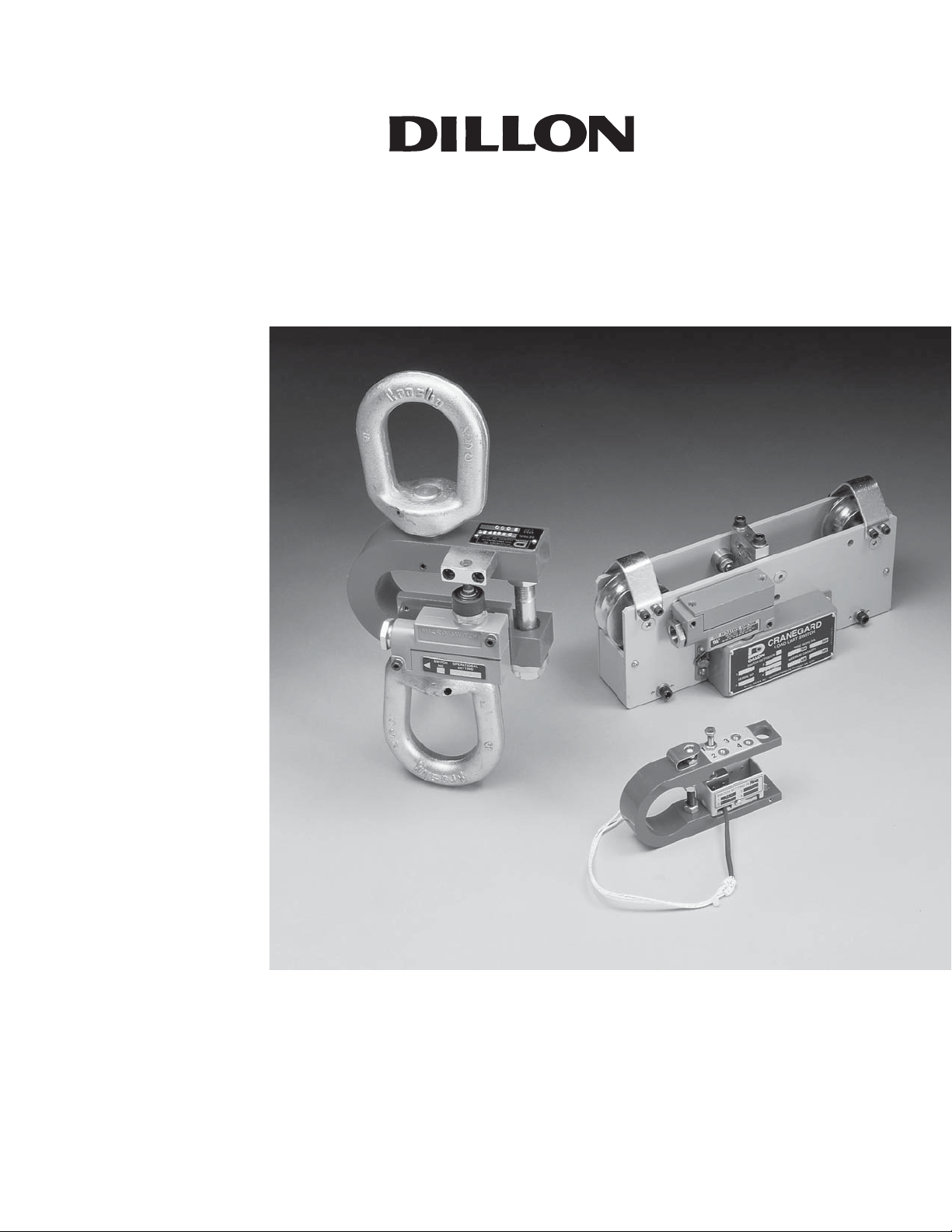
The primary purpose of Model DS Dynaswitches® is to protect cranes,
hoists and other lifting machinery against weight or force overload damages. They can also be used to perform control functions proportional to
weight such as shutting down a pump when a tank is filled. As many as
four standard microswitches can be installed on the Dillon Dynaswitch to
perform multiple automated functions. The Dynaswitch is intended for
applications with gradually applied loads and should not be installed where
it may encounter severe dynamic or impact loads.
Dillon Dynaswitches are designed to work with either a tension or compression load. All Dynaswitches consist of a U-shaped force beam, a
microswitch (or microswitches), and attachment fittings for applying load at
mounting points. The force beam bends as force is applied and causes the
microswitches to open or close electrical circuits. Illustrations on pages 7
and 8 show various microswitches and attachment fittings. Dynaswitch
capacity should be selected based on maxiumum forces it may encounter,
including load-increasing factors such as acceleration of mass and static
arrangement of cables.
1-3
Safety
1-4
Compression Models
1-5
Tension Models
All Dynaswitch force beams and attachment fittings have a safety factor of
5:1. In addition, all models have an overload stop, set slightly in excess of
rated capacity to prevent damage to measuring capability.
When loads are applied to compression models, the force beam legs tend
to come closer together. Paragraph 2-6-A explains how to hook up safety
overload circuits and auxiliary circuits of compression models’ microswitches. Compression models contain threaded holes on the bottom
leg for mounting to machinery and a spherical bearing on the top leg to
concentrate the applied load at one point. The stops for measuring capability protection are adjustable bolts in all capacities except 25K and 50K,
where this stop is integral with the force beam.
When loads are applied to tension models, the force beam legs tend to
spread apart. Paragraph 2-6-B explains how to hook up safety overload
circuits and auxiliary circuits to tension models’ microswitches. Tension
model attachment fittings include spherical rod end connectors, shackles,
lifting eyes, non-swivel hooks and threadstuds. Attachment fittings are
mounted on opposite legs and are in-line axially so the applied load will not
cause rotation of the beam. The stops for measuring capability protection
are adjustable bolts in all capacities.
5
Page 6

1-6
Table 1-1, below, contains key specifications and options available.
Key Specifications
and Options
Table 1-1
Basic Beam DSW-1 DSW-2 DSW-3 DSW-4 DSW-5 DSW-6 DSW-7
Part Number
Rated
Capacity 100 1000 2000 5000 10000 25000 50000
pounds
Minimum 15 100 200 500 1000 1250 2500
Set point*
Repeatability ±3 ±30 ±60 ±150 ±300 ±750 ±1500
pounds
Nomi--l full
Cap. beam 0.02 0.03 0.05 0.05 0.05 0.06 0.06
deflection
in inches
Option A Avail. Avail. -- Avail. -- -- --
Option J Avail. Avail. -- Avail. -- -- --
Option B -- -- Avail. -- Avail. Avail. Avail.
Option C -- -- Avail. -- Avail. Avail. Avail.
Option D Avail. Avail. -- -- -- -- --
Option E Avail. Avail. Avail. Avail. Avail. Avail. Avail.
Option F -- -- Avail. -- Avail. -- --
Option G -- -- Avail. Avail. Avail. Avail. Avail.
Hardware Switch
Option H -- -- Avail. -- Avail. -- --
Option S Avail. Avail. Avail. Avail. Avail. Avail. --
Option A .001" differential travel switch; small size. P/N 26419-0026
Type 11SM401-T. Maximum 4 per unit.
Option J .004" differential travel switch; weatherproof, small size.
26420-0015 . Type 1SE1. Maximum 4 per unit.
Option B .002" differential travel switch; weatherproof. P/N 17891-0048
Type BZG1-2RN. Maximum 4 per unit.
Option C Explosion proof switch. 26424-0029. Type EXA-0. Maximum 2
per unit.
Option D Spherical rod end connector (one).
Option K Compression loading spherical ball fitting assembly (one).
Optioa F Lifting eye (one)
Option G Adapter, shackle & pin (one set).
Option H Non-swivel hook (one).
Option S Stud for tension loading (one).
6
Page 7
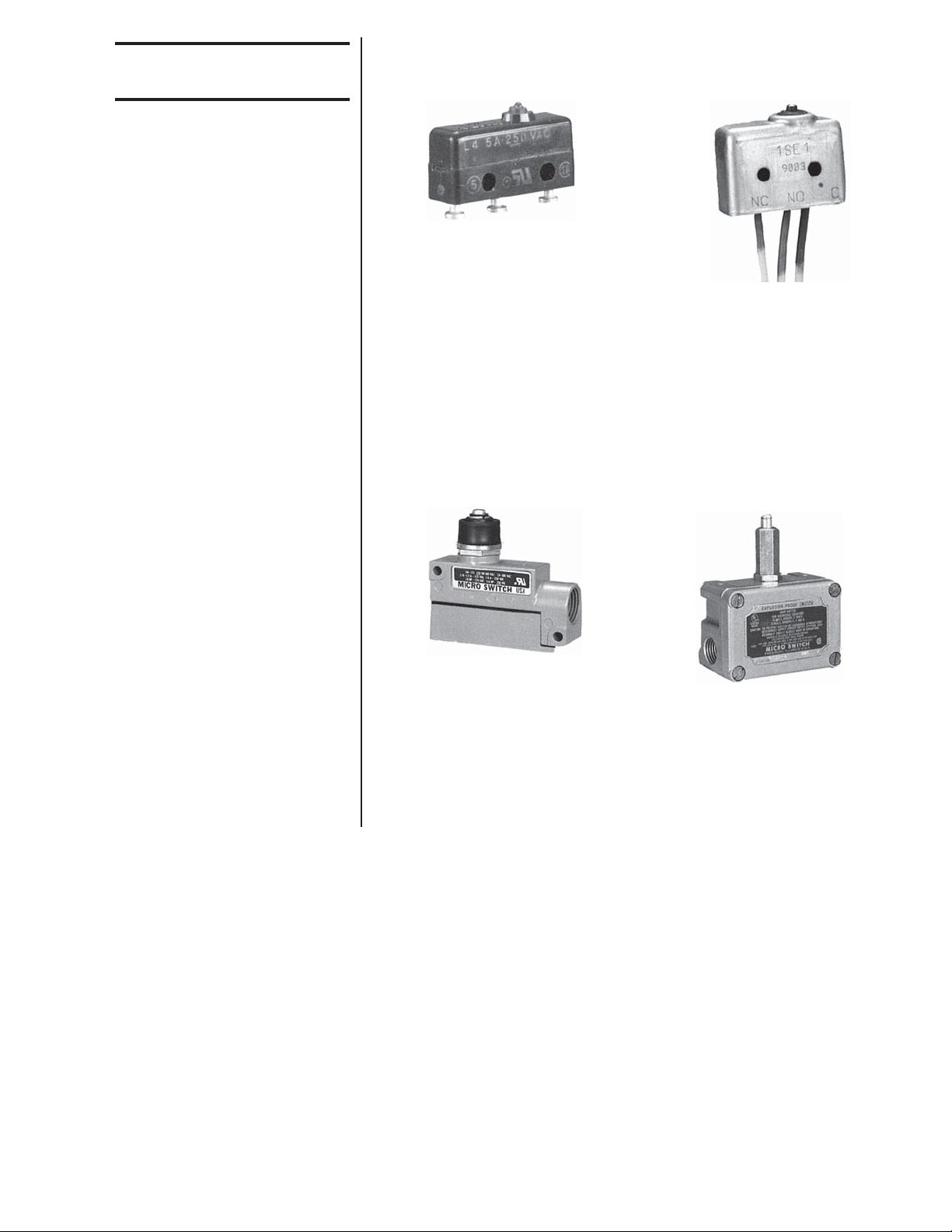
1-7
Microswitches
Below are the four microswitches available and their specifications.
Option A:
0.001” differential travel switch.
Small size
Dillon PN 26419-0026
(Cat. #11SM401-T.) S.P.D.T.
5 amps. resistive at 28VDC or
250VAC
Option J:
0.004” differential travel switch
Small size
Weatherproof
Dillon PN 26420-0015
(Cat. #1SE1.) S.P.D.T.
5 amps. resistive at 28VDC, 125 or
250VAC
Option B:
0.002” differential travel switch
Weatherproof
Dillon PN 17891-0048
(Cat. #BZG1-2RN.) S.P.D.T.
15 amps. resistive at 125, 250 or
480VAC. ½ amp. at 125VDC.
Option C:
0.060” differential travel switch
Explosion proof
Dillon PN 26424-0029
(Cat. #EXA-Q.) S.P.D.T.
20 amps. resistive at 125, 250 or
480VAC. ½ amp. at 125VDC.
7
Page 8
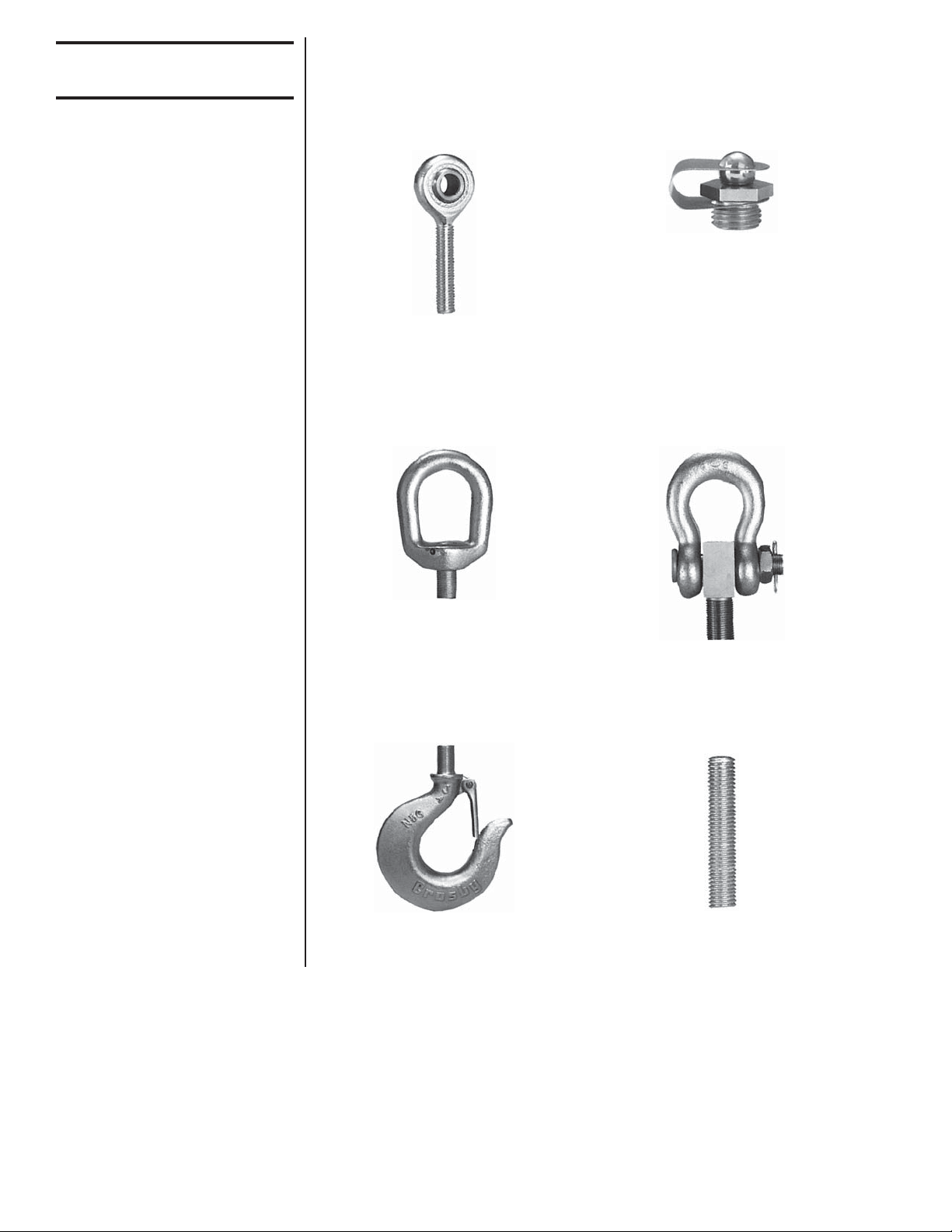
1-8
Attachment Fittings
Attachment fittings for tension and compression models are shown below.
Illustrations are not to scale.
Option E:
Compression loading spherical ball
fitting assembly
Option D:
Spherical rod end connector
Option F: Lifting eye
Option H:
Nonswivel hook
Option G:
Adapter, shackle and pin (one set)
Option S:
Threaded stud
8
Page 9

Section 2 Installation
2-1
Mounting Positions
Tension Models
2-2
Mounting Positions
Compression Models
Some compression models
have flat-top balls; rest the
applied load on the flat
surface of the flat-top ball.
The best mounting position for a tension model is on the dead end of the
line or on a crane anchor point. This mounting minimizes the effects of the
machinery’s motion on the Dynaswitch. It keeps the switch in one relative
position which reduces the possibility of wire tangling and connector
damage.
Position the Dynaswitch so that all of the supported load is transmitted
through the compression ball fitting. Bolt the bottom leg to the loading
machinery or the facility foundation. Make sure the load contacts the
Dynaswitch only at the top of the steel ball and nowhere else! If the load
rests on the upper leg as well as on the ball, the microswitches will not
actuate at the proper load setting. Do not restrict free motion of the upper
leg since this too could cause the Dynaswitch to activate improperly.
9
Page 10

2-3
Dynaswitches &
Reeving Setups
Below are some examples of hoist and reeving setups which use the
Dynaswitch for control and/or safety purposes.
Figure 2-A
2 ropes, 2 part single
reeving
Figure 2-B
As shown at right, Dynaswitch is
installed in series with rope to the
dead end. The microswitch is set
for ¼ capacity of the crane because
there are four parts of line to the
hook.
With two parts of line to the hook,
the Dynaswitch should be installed
in series between wire rope and its
dead end point. Microswitch is set
for ½ maximum capacity of the
hoist.
Frictional reactions within the
sheaves may prevent all parts
of the lines from having identical tension. While generally
suitable for overload protection,
it may give unsatisfactory
results for weighing or batch
control.
10
Figure 2-C
4 ropes, 4 part single
reeving
Figure 2-D
The Dynaswitch may also be placed
between hoist and trolley with
microswitch set for maximum
capacity of the hoist and trolley.
Page 11
2-4
Other Installation
Possibilities
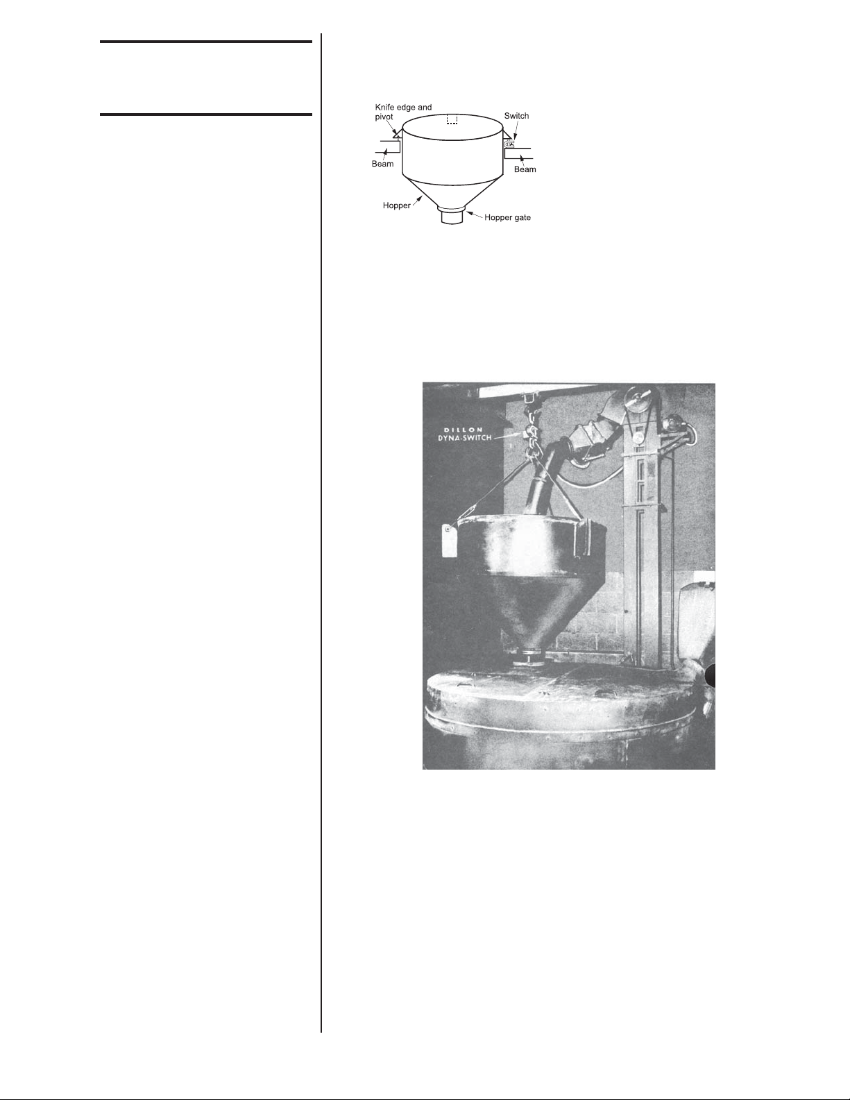
Figure 2-E and 2-F show other uses for the Dynaswitch when either
tension or compressions loads are present.
Batching operations at preset load
points are greatly simplified by
means of economical Dillon
Dynaswitches. Figure 2-E shows a
typical hopper with 3 point suspension. Dynaswitch under one suspension point is set for 1/3 maximum load. It opens hopper gate
automatically at this point. Contents
Figure 2-E
of tank should preferably be liquid,
since solid materials tend to pile
and cause erroneous results.
Figure 2-F
Figure 2-F shows an example of using the Dynaswitch in an automatic
control function. Sand used in foundry operations is brought up from the
floor below by conveyor. It falls into the chute and then spills into the
hopper. The hopper itself is suspended from the Dynaswitch at upper left.
The Dynaswitch is set to open the conveyor motor circuit at 1000 pounds
which represents a full hopper. At the same instant, a trap in the bottom of
the hopper also opens permitting contents to flow out into a mixer below. A
time delay switch on the hopper trap holds it open until all sand has been
discharged at which time the reduced load on the Dynaswitch causes it to
again close the conveyor motor circuit and repeat the cycle endlessly.
The Dynaswitch is also acting as a precision scale since it is set to function at a specific load point. Any form of batching operation can be easily
automated by this simple arrangement.
11
Page 12

2-5
Dynaswitch Selection
To pick the proper sized Dynaswitch for the job, do the following:
1. Determine the mounting position.
2. Calculate the load to be applied to the Dynaswitch.
3. Refer to Table 1-1 to select a Dynaswitch with the proper capacity and
minimum/maximum set point range.
2-6
Dynaswitch Field
Installation Procedures
2-6-A
Wiring the Compression
Model Dynaswitch
2-6-B
Wiring the Tension Model
Dynaswitch
You can put together a test
assembly consisting of an
indicator light or horn, a power
source and two leads with
alligator clips to simulate the
machinery’s control circuit.
Loads applied to compression Dynaswitches cause the force beam legs to
deflect and come closer together. Loads applied to tension units cause the
force beam legs to deflect outward and spread apart. Microswitches are
S.P.D.T. and have three contact terminals. One is normally open, one
normally closed, and one is common. Therefore they can be wired to
make or break a circuit at specific set point(s).
To make a circuit:
1. on increasing compression load, use common and normally open
contacts.
2. on decreasing compression load, use common and normally closed
contacts.
To break a circuit:
1. on increasing compression load, use common and normally closed
contacts.
2. on decreasing compression load, use common and normally open
contacts.
To make a circuit:
1. on increasing tension load, use common and normally closed contacts.
2. on decreasing tension load, use common and normally open contacts.
To break a circuit:
1. on increasing tension load, use common and normally open contacts.
2. on decreasing tension load, use common and normally closed
contacts.
Any time the Dynaswitch is
removed from the machinery and reinstalled, you
must check the switch
operation. Failure to do so
could result in inaccurate
actuation as the calibration
could change.
12
Page 13

2-6-C
Setting the Set Points
1. Figure the desired set point, in pounds, for each microswitch. In
setting two, three or four switches, set the highest set point first, then
work down according to weight. Any other sequence will cause a
shutdown during the adjusting process.
2. Turn the adjustment screw: In compression models, back the
adjustment screw as far as it will go
away from the switch plunger.
In tension models, turn the adjustment screw as far as it will go into the
switch plunger without damaging the
switch.
3. Apply a load on the unit equal to the desired setting. You must apply
an accurately measured load because the set point accuracy will be
no better than the known accuracy of the measured load.
4. Slowly turn the adjustment screw:
In compression, turn the screw until it
is just low enough to actuate the
switch. Then tighten the jam nut to
hold the adjustment.
In tension, turn the screw until it is just
high enough to actuate the switch
plunger. Then tighten the jam nut to
hold the adjustment.
5. Remove, then reapply the load to check the set point. It is properly set
if the machinery, or the test assembly, functions as planned within
desired tolerances.
6. Repeat steps 1-5 as many times as required to obtain correct settings.
Your Dynaswitch is now ready to use. It is recommended that you double
check your installation before beginning operation.
13
Page 14

Low Differential Travel Switch
(For 100, 1,000 and 5,000 lb beams only)
Circuitry
Single pole
Double throw
Electrical Data
UL Rating:
5 AMPS, 125 or 250VAC
Weatherproof Low Differential Travel Switch
(For 2,000, 10,000, 25,000 and 50,000 lb beams only)
Electrical DataCircuitry
UL Rating: L 74
15 AMPS, 125, 250 or 480 VAC;
2 AMPS, 600 VAC;
Single pole
Double throw
1/8 HP, 125 VAC; 1/4 HP, 250 VAC;
.5 AMPS, 125 VDC; .25 AMP 250 VDC.
Explosion-Proof Switch
(For 2,000, 10,000, 25,000 and 50,000 lb beams only)
Electrical DataCircuitry
UL Rating: L 23
20 AMPS, 125, 250 or 480 VAC;
10 AMPS, 125 VAC “L”;
Single pole
Double throw
1 HP, 125 VAC; 2 HP, 250 VAC;
.5 AMPS , 125 VDC; .25 AMP 250 VDC.
Weatherproof Low Differential Travel Switch
(For 100, 1,000 and 5,000 lb beams only)
Electrical DataCircuitry
5 AMPS Res., 3 AMPS Ind., (Sea level),
4 AMPS Res., 2 AMPS Ind., (50,000 feet)
28 VDC
Single pole
Double throw
5 AMPS Res. or Ind. 115 VAC, 60 Hz.
UL/CSA Rating: 5 AMPS, 250 VAC.
14
Page 15

Section 3 Operation
3-1
Safety Shutdown
Function
3-2
Decreasing Load
Operation
3-3
Automation Operation
DO NOT override the safety shutdown circuit. This can result in injury to
workers and damage to equipment.
Ensure that the Dynaswitch triggers both the increasing and decreasing
load function as planned. Stop the machinery and adjust the switch or
setup if a problem exists.
Ensure the automated machinery setup is working properly. If it is not, stop
the machinery and adjust either the Dynaswitch or the other components
of the setup until it does work properly.
Section 4 Maintenance
4-1
General Instructions
4-2
Service Instructions
Service the Dynaswitch at least once every six months (more often if it is
exposed to extreme climate or working conditions) according to paragraph
4-2, below. In addition, check the accuracy of the microswitch at least
once every six months (more often if it is part of a setup which receives
frequent use) and reset the microswitch as required. Switch setting
procedures are outlined in paragraph 2-6.
A. Attachment Fittings - Check for unusual wear, deformation, looseness
B. Micro-Switches - Replace if wires are frayed or if the connection
C. Overload Stop - Make sure no foreign material is present in overload
D. Adjustment screws, overload devices, switch and screw mounting
and corrosion. Replace if damaged or loose. Clean off corrosion; oil
compression steel ball fitting as required.
plunger or housing is damaged in any way.
stop gap, since this could cause errors.
brackets - Replace the component if it is damaged or deformed
enough not to work as designed.
E. Force Beams - Cleaning corrosion and painting are the only authorized
services. If the force beam has suffered damage or permanent
deformation, replace the entire Dynaswitch.
15
Page 16

4-3
Authorized
Replacement
A. Attachment Fittings - The customer is authorized to replace only
shackle and pin attachment fittings at their facility. Customers desiring
replacement of any other attachment fitting must return the
Dynaswitch to Dillon or a factory authorized distributor for attachment
fitting replacement. The reason for this is that all attachment fittings
other than shackles and pins are pinned to the force beam after
assembly.
B. Microswitches - Addition and replacement of microswitches, as well as
conversion from one type to another is authorized as long as the user
orders the proper Dillon microswitches. Microswitch mounting brackets and adjustment screw mounting brackets are available for all
authorized configurations. Switch calibration is required after such
service.
C. Other Parts - The replacement of parts other than shackle and pin
attachment fittings, authorized microswitches and microswitch mounting hardware is not authorized. Attempting to make unauthorized
repairs on the Dynaswitch automatically voids the Dillon warranty.
4-4
Troubleshooting
Problems are generally limited to the Dynaswitch actuating too soon, too
late or not at all.
Recommended troubleshooting procedure:
A. Ensure there is power to the circuits involved.
B. Reset the microswitches.
C. Check the microswitch and the circuit for continuity.
D. Check the functions of the machinery setup (for items that would
cause improper actuation).
Most problems will be found in one of these areas.
Excessive wear in attachment fittings is caused by excessive loading,
improper installation or abnormal machinery travel. Replace damaged
fittings and correct the machinery installation or loading problem.
16
Page 17

Section 5 Cranegard® Load Limit Switch
5-1
Introduction
5-2
General Description
5-3
Safety Factor
The Dillon Cranegard Load Limit Switch is used to protect cranes and
hoists against overloading where it is impossible or inconvenient to use a
Dillon Dynaswitch. This unit can be applied to wire rope without cutting or
removing the dead end from its existing mount. It may also be used on
machinery such as elevators to provide a switch action at a given load.
The Cranegard is intended for applications with gradually applied tensions
and not dynamic or impact loads.
The Dillon Cranegard Load Limit Switch is designed to clamp directly onto
typical hoist or crane rope. It consists of two side plates. Two steel
sheaves which are equipped with precision bearings, a rope clamp and
center support which in turn is attached to a flexure. Arm(s) on the flexure
can actuate as many as four microswitches at preset load points. Adjustment screws for the switches are located under a sealed cover.
The Dillon Cranegard Load Limit Switch flexure beam has a safety factor
of 2:l. Ultimate safety factor is a function of wire rope condition. In the
interest of safety, damaged or worn wire rope should be replaced.
5-4
Micro-Switches
The microswitch is type BZG1-2RN, weatherproof, Dillon P/N 17981-0048
(paragraph 1-7). As many as four switches can be installed on one
Cranegard unit.
Table 5-1, below, indicates capacities and other specifications.
5-5
Key Specifications
Table 5-1
Part Capacity Min. Set Repeatability Rope Diameter Inches
Number Pounds Point Lb Pounds
CGS-1 2500 100 75 3/16 1/2
CGS-2 5000 200 150 3/8 7/8
Minimum Maximum
CGS-3 10000 400 300 7/16 7/8
CGS-4 20000 800 400 5/8 1 1/4
17
Page 18

Section 6 Installation
6-1
Mounting Positions
The best mounting position for the Cranegard Load Limit Switch is adjacent to the wire rope dead end point. It also could be installed adjacent to
the equalizer sheave where wire rope movement is small (a few inches).
The amount of wire rope movement around the equalizer sheave should
be measured by marking the wire rope, noting the amount of movement,
and allowing enough clearance for such movement when mounting the
Cranegard unit.
6-2
Selection
18
Figure 6-A
To pick the proper size Cranegard Load Limit Switch for the job, do the
following:
A. Measure the diameter of the rope on which the Cranegard Load Limit
Switch is to be installed.
B. Calculate the maximum load to be applied to the Cranegard Load Limit
Switch, using capacity of the hoist or crane and number of parts of line
to the hook (refer to 2-3).
C. Choose the number of switches and set point.
D. Refer to table 5-1 for proper selection.
Page 19

6-3
Cranegard Field
Installation Procedures
A. The Cranegard is designed to be mounted on a slack line. If line is not
slack, methods should be employed to shunt load in the cable area
where Cranegard will be installed. Often wire grips and portable
winches are used to accomplish this.
B. Position the Cranegard at the desired location on wire and loosely attch
the clamp wit the included screws. Tighten the screws so that the
cable is loosely gripped between the top and the bottom of the clamp.
Insure the same gap exists between the upper and lower clamps on
both sides.
C. Check switch operation using a voltmeter or other method for monitor-
ing open/closing of switch contacts. If specific loads were indicated at
the time of order, Dillon will calibrate to these values at the factory
prior to shipment. Once installed, there may be diffrences between
calibration and actual trigger values. Differences in rope type &
diameter, temperature, and external mechanisms (such as sheaves)
can affect the switch activation points. If more precise calibration is
required, it should be calibrated under the conditions used.
D. If field calibration is required, follow the additional instructions below.
E. Remove the protective cover to expose adjustment screws.
F. Refer to Paragraph 2-6, Notes 1 and 2, for information on construction
of a test assembly for switch adjustment.
G. Figure the desired set point for each microswitch. In setting two, three
or four switches, set the highest set point first, then work down according to weight. Any other sequence will cause a shutdown during the
adjusting process.
H Turn the adjustment screw(s) counterclockwise, away from the
microswitch plunger(s) as far as possible.
I. Apply the trigger load, insuring that the cutoff load is approached from
the desired direction. For increasing loads, such as overload detection,
gradually apply the load. For decreasing loads, such as slack-line
detection, apply at least 5% more load (of Cranegard capacity) than is
desired for switch trigger, then gradually reduce the load until trigger
load is reached.
J. Slowly turn the adjustment screw until it contacts the microswitch
plunger and the switch actuates. Then tighten the jam nut to hold the
adjustment.
K. Remove, then reapply the load to check the set point. It is properly set
if the machinery (or the test assembly) functions as planned within
desired tolerances.
L. Repeat steps G through K as many times as required to obtain correct
settings.
Figure 6-B
19
Page 20

6-4
Electrical Wiring
Micro-switch(es) are S.P.D.T. and have three contacts. One is normally
open, one normally closed, and one is common. Therefore they can make
or break a circuit (start or stop an operation) at a specific set point(s).
Any time the Dynaswitch is
removed from the machinery and reinstalled, you
must check the switch
operation. Failure to do so
could result in inaccurate
actuation as the calibration
could change.
To BREAK a circuit at a set point as load increases, select normally closed
and common switch terminals. To MAKE a circuit as load increases, wire
to normally open and common terminals.
To BREAK a circuit at a set point as load decreases, wire to common and
normally open terminals. To MAKE a circuit as load decreases, wire to
common and normally closed terminals.
Section 7 Maintenance
7-1
General Instruction
7-2
Mechanical Inspection
Depending on environmental and working conditions, Cranegard Load
Limit Switches should be inspected periodically, at least every six months.
Cranegard Load Limit Switches should be free from any contact friction of
adjacent wire rope.
7-3
Electrical Inspection
7-4
Switch Setting
7-5
Authorized Parts
Replacement
7-6
Troubleshooting
Check for frayed wires, damage to the microswitch housing and protective
cover.
Check established operating setting(s). If necessary, the switches should
be reset.
Type BZG1-2RN microswitches are the only authorized parts replacements for Cranegard Load Limit Switches. Attempting to make unauthorized repairs to the Cranegard Load Limit Switch automatically voids the
Dillon warranty.
Follow the procedure for the Dynaswitch in section 4-4.
Dillon
A division of Weigh-Tronix Inc.
1000 Armstrong Dr.
Fairmont, MN 56031 USA
Telephone: 507-238-4461
Facsimile: 507-238-8258
e-mail: dillon@weigh-tronix.com
www.dillon-force.com
Weigh Bar® is a registered trademark of Weigh-Tronix Inc.
11/06/03 DS&CG_U.P65 PN 16947-0010G e2 Printed in USA
Force Measurement Products & Systems
 Loading...