

DIGIWEIGH DWP-10000F User Manual

NTEP Floor / Pallet Scale
DWP-5500F 2X2
DWP-5000F 3X3
DWP-5000F 4X4
DWP-5000F 5X5
DWP-10000F 5X5
DWP-10000F 4X6
DWP-101(Indicator)
User Manual

Content
CHAPTER 1 MAIN SPECIFICATION
CHAPTER 2 INSTALLATION
CHAPTER 3 INDICATOR
1
Chapter 1 Main Specification
1. Model: DWP-F SERIES NTEP Floor / Pallet scale
2. Accuracy: GradeⅢ, n=5000
3. Sample Rate: 10 times/second
4. Load cell sensitivity 1.5~3mV / V
5. Scale interval: 1/2/5/10/20/50 for option
6. Display: 6 bits LED, 8 state indicating signals
7. Power supply: AC100V~230V,50~60HZ
8. Operating temperature/humidity: 0~50℃; ≤90%RH
9. Transporting temperature: -20~60℃
Chapter 2 Installation
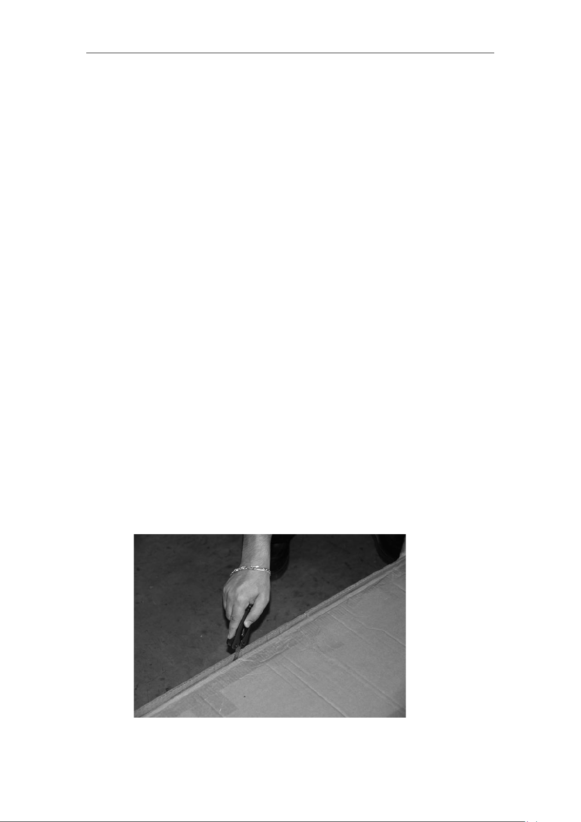
2.0 SCALE BASE SETUP
a. Open the scale base box (Box 1) with a knife very carefully. Sharp blade may
scratch the scale surface.
2
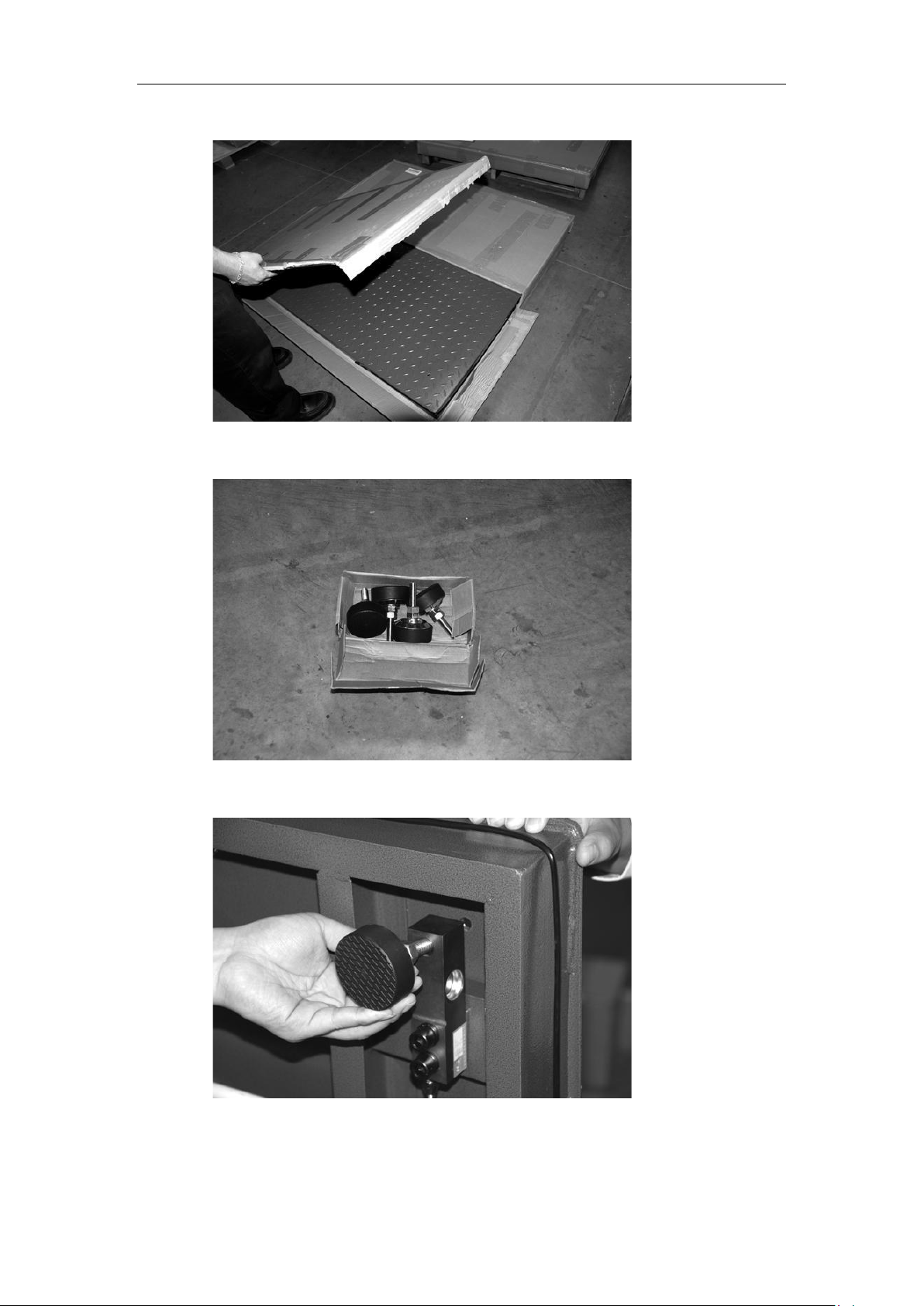
b. Take out the scale feet (total 4 feet packed in the box inside the scale base)
c. Screw each foot ontothe load cell at each corner of the scale base.
3

d. Take out the indicator from Box 2. Plug the scale serial cable into the socket on
the back of the indicator. And use a screw driver to tighten the two screws of the
plug.
Turn on the indicator by pressing the ON/OFF button on the front of the
indicator.
Now your scale is ready to use. For advanced operations, please refer to the
following pages.
4
Chapter 3 Indicator
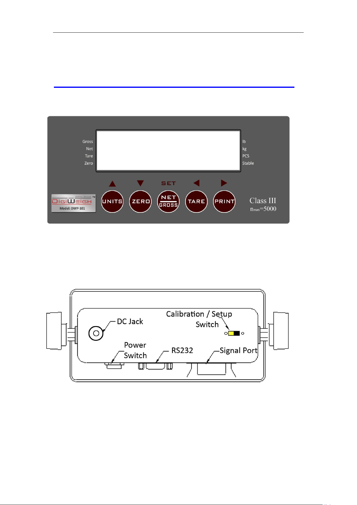
Front and back view of the indicator
Front:
Back:
5
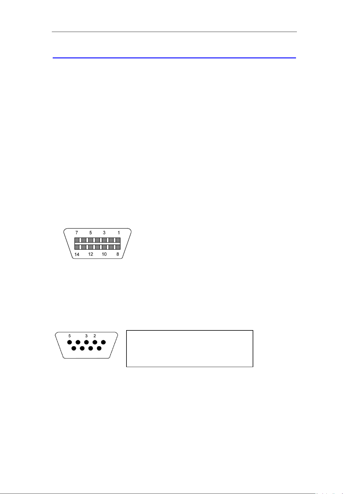
1/8
+Excitation
3/10
-Excitation
5/12
+Signal
7/14
-Signal
2 Receive Data
3 Transmit
5 Signal Ground RS-232
Connections
Connection with Weigh Platform
The indicators mounted in an ABS enclosure ship with a 15 ft shielded load cell cable for
a connection to weigh platform’s load cell(s) or junction box.
1. Plug the cable’s 14-pin connector into the signal port on the rear panel of the
indicator. Wire the bare wires and shield to the weigh platform’s load cell(s) or
junction box using the color codes shown below:
RED: +Excitation
BLACK: - Excitation
GREEN: +Signal
YELLOW: - Signal
2. 2. If you do not wish to use the shielded load cell cable, you may use own, following
the pin assignments shown below:
Connection with Printer or Computer
The indicator comes standard with one full duplex RS-232 serial port, designed for
connection to either a PC or a serial printer. Below is the diagram:
Plug the serial printer, remote display or computer communication cable (not included)
directly into the D-SUB9 serial port connector.
Connection with Power Supply
The indicator comes with an external AC adapter. Simply plug the AC adapter into the its
DC Power Jack first, and then plug into a standard wall outlet.
6
 Loading...