

Page 1
Page 2

Page 3

Page 4
WARNING FOR YOUR PROTECTION
PLEASE READ THE FOLLOWING:
KEEP THESE INSTRUCTIONS
HEED ALL WARNINGS
FOLLOW ALL INSTRUCTIONS
DO NOT USE THIS APPARATUS NEAR WATER
CLEAN ONLY WITH A DR
Y CLOTH.
DO NOT BLOCK ANY OF THE
VENTILATION OPENINGS. INSTALL
IN ACCORDANCE
WITH THE MANUFACTURER’S INSTRUC-
TIONS.
DO NOT INSTALL NEAR ANY HEA
T SOURCES SUCH AS RADIA-
TORS, HEAT REGISTERS,
STOVES, OR OTHER APPARATUS
(INCLUDING AMPLIFIERS) THAT PR
ODUCE HEAT.
ONLY USE ATT
ACHMENTS/ACCESSORIES SPECIFIED BY THE MAN-
UFACTURER.
UNPLUG THIS APPARATUS DURING LIGHTNING STORMS OR
WHEN UNUSED FOR LONG PERIODS OF TIME.
Do not defeat the safety purpose of the polarized or grounding-type
plug. A polarized plug has two blades with one wider than the other. A
grounding type plug has two blades and a third grounding prong. The
wide blade or third prong are provided for your safety. If the provided
plug does not fit your outlet, consult an electrician for replacement of
the obsolete outlet.
Protect the power cord from being walked on or pinched particularly
at plugs, convenience receptacles, and the point where they exit from
the apparatus.
Use only with the car
t stand, tripod bracket,
or table specified by the
manufactur
e, or sold with the a
pparatus. When a car t is used,
use cau-
tion when moving the car
t/apparatus combination to av
oid injury from
tip-ov
er.
Refer all ser
vicing to to qualified service personnel. Ser
vicing is
requir
ed when the apparatus has been damaged in any wa
y, such as
power-supply cord or plug is damaged, liquid has been spilled or objects
have fallen into the apparatus, the apparatus has been exposed to rain
or moisture, does not operate normally, or has been dropped.
POWER ON/OFF SWITCH: For products provided with a power
switch,the power switch DOES NOT break the connection from the
mains.
MAINS DISCONNECT: The plug shall remain readily operable. For
rack-mount or installation where plug is not accessible, an all-pole
mains switch with a contact separation of at least 3 mm in each pole
shall be incorporated into the electrical installation of the rack or building.
FOR UNITS EQUIPPED WITH EXTERNALLY ACCESSIBLE FUSE
RECEPTACLE: Replace fuse with same type and rating only.
MULTIPLE-INPUT VOLTAGE: This equipment may require the use of a
different line cord,attachment plug,or both,depending on the available
power source at installation.Connect this equipment only to the power
source indicated on the equipment rear panel.To reduce the risk of fire
or electric shock, refer servicing to qualified service personnel or
equivalent.
This Equipment is intended for rack mount use only.
SAFETY INSTRUCTIONS
NOTICE FOR CUSTOMERS IF YOUR UNIT IS EQUIPPED
WITH A PO WER CORD.
WARNING:THISAPPLIANCE MUST BE EARTHED.
The cores in the mains lead are coloured in accordance with
the following code:
GREEN and YELLOW - Earth BLUE - Neutral BR O WN - Liv e
As colours of the cores in the mains lead of this appliance may
not correspond with the coloured markings identifying the terminals in your plug,proceed as follows:
• The core which is coloured green and yellow must be
connected to the terminal in the plug marked with the
letter E,or with the earth symbol, or coloured green, or
green and yellow.
• The core which is coloured blue must be connected to
the terminal marked N or coloured black.
• The cor e which is colour ed br own m ust be connected to
the terminal marked L or coloured red.
This equipment may require the use of a different line cord,
attachment plug, or both, depending on the available power
source at installation. If the attachment plug needs to be
changed, refer servicing to qualified service personnel who
should refer to the table below. The green/yellow wire shall be
connected directly to the units chassis.
WARNING:If the gr ound is def eated,certain fault conditions in
the unit or in the system to which it is connected can result in
full line voltage between chassis and earth ground. Severe injury
or death can then result if the chassis and earth ground are
touched simultaneously.
The symbols shown above are internationally accepted
symbols that warn of potential hazards with electrical
products. The lightning flash with arrowpoint in an equilateral triangle means that there are dangerous voltages
present within the unit. The exclamation point in an equilateral triangle indicates that it is necessary for the user to
refer to the owner’s manual.
These symbols warn that there are no user serviceable
parts inside the unit. Do not open the unit. Do not
attempt to service the unit yourself. Refer all servicing to
qualified personnel. Opening the chassis for any reason
will void the manufacturer’s warranty. Do not get the unit
wet. If liquid is spilled on the unit, shut it off immediately
and take it to a dealer for service. Disconnect the unit
during storms to prevent damage.
IMPORTANT SAFETY INSTRUCTIONS
CONDUCTOR
L
LIVE
NEUTRAL
N
E
EARTH GND
WIRE COLOR
Normal Alt
BROWN
BLUE
GREEN/YEL
BLACK
WHITE
GREEN
Page 5
U.K. MAINS PLUG WARNING
A molded mains plug that has been cut off from the cord is unsafe. Discard
the mains plug at a suitable disposal facility. NEVER UNDER ANY CIRCUMSTANCES SHOULD YOU INSERT A DAMAGED OR CUT MAINS PLUG
INTO A 13 AMP POWER SOCKET. Do not use the mains plug without the
fuse cover in place. Replacement fuse covers can be obtained from your local
retailer. Replacement fuses are 13 amps and MUST be ASTA approved to
BS1362.
LITHIUM BATTERY WARNING
CAUTION!
This product may contain a lithium battery.There is danger of explosion if the battery is incorrectly replaced.
Replace only with an Eveready CR 2032 or equivalent.
Make sure the battery is installed with the correct polarity. Discard used batteries according to manufacturer’s
instructions.
ADVARSEL!
Lithiumbatteri - Eksplosjonsfare.Ved utskifting benyttes
kun batteri som anbefalt av apparatfabrikanten. Brukt batteri returneres apparatleverandøren.
ADVARSEL!
Lithiumbatteri - Eksplosionsfare ved fejlagtig håndtering.
Udskiftning må kun ske med batteri av samme fabrikat og
type. Levér det brugte batteri tilbage til leverandøren.
VAROITUS!
Paristo voi räjähtää,jos se on virheellisesti asennettu.
Vaihda paristo ainoastaan laitevalmistajan suosittelemaan
tyyppin.Hävitä käytetty paristo valmistajan ohjeiden
mukaisesti.
VARNING!
Explosionsfara vid felaktigt batteribyte.Använd samma batterityp eller en ekvivalent typ som rekommenderas av
apparattillverkaren.Kassera använt batteri enligt fabrikantens instruktion.
IMPORTANT SAFETY INSTRUCTIONS
ELECTROMAGNETIC
COMPATIBILITY
This unit conforms to the Product
Specifications noted on the Declaration
of Conformity. Operation is subject to
the following two conditions:
• this device may not cause harmful
interference,and
• this device must accept any interference received, including interference
that may cause undesired operation.
Operation of this unit within significant
electromagnetic fields should be avoided.
• use only shielded interconnecting
cables.
Manufacturer’s Name: DigiTech
Manufacturer’s Address: 8760 S.Sandy Parkway
Sandy, Utah 84070, USA
declares that the product:
Product name: GNX4
Note:Product name may be suffixed by the letters EU,JA, NP
and UK.
Product option: all (requires Class II power
adapter that conforms to the
requirements of EN60065,
EN60742,or equivalent.)
conforms to the following Product Specifications:
Safety: IEC 60065 (1998)
EMC: EN 55013 (1990)
EN 55020 (1991)
Supplementary Information:
The product herewith complies with the requirements of the
Low Voltage Directive 72/23/EEC and the EMC Directive
89/336/EEC as amended by Directive 93/68/EEC.
Vice-President of Engineering
8760 S.Sandy Parkway
Sandy, Utah 84070, USA
Date:March 15, 2004
European Contact: Your local DigiTech Sales and
Service Office or
Harman Music Group
8760 South Sandy Parkway
Sandy, Utah 84070 USA
Ph:(801) 566-8800
Fax:(801) 568-7583
DECLARATION OF
CONFORMITY
Page 6

Warranty
We at DigiTech are very proud of our products and back-up each one we sell with the following warranty:
1. The warranty registration card must be mailed within ten days after purchase date to validate this
warranty.
2.DigiTech warrants this product, when used solely within the U.S.,to be free from defects in materials and
workmanship under normal use and service.
3.DigiTech liability under this warranty is limited to repairing or replacing defective materials that show
evidence of defect,provided the product is returned to DigiTech WITH RETURN AUTHORIZATION,
where all parts and labor will be covered up to a period of one year.A Return Authorization number may
be obtained from DigiTech by telephone. The company shall not be liable for any consequential damage as
a result of the product's use in any circuit or assembly.
4.Proof-of-purchase is considered to be the burden of the consumer.
5.DigiTech reser ves the right to make changes in design,or make additions to,or improvements upon this
product without incurring any obligation to install the same on products previously manufactured.
6. The consumer forfeits the benefits of this warranty if the product's main assembly is opened and
tampered with by anyone other than a certified DigiTech technician or,if the product is used with AC
voltages outside of the range suggested by the
manufacturer.
7. The foregoing is in lieu of all other warranties,expressed or implied, and DigiTech neither assumes nor
authorizes any person to assume any obligation or liability in connection with the sale of this product. In
no event shall DigiTech or its dealers be liable for special or consequential damages or from any delay in
the performance of this warranty due to causes beyond their control.
NOTE: The information contained in this manual is subject to change at any time without
notification. Some information contained in this manual may also be inaccurate due to
undocumented changes in the product or operating system since this version of the manual
was completed. The information contained in this version of the owner's manual supersedes all
previous versions.
Page 7

Introduction . . . . . . . . . . . . . . . . . . . . . . . . . . .1
Included Items . . . . . . . . . . . . . . . . . . . . . . . . . . . . .1
Quick Start . . . . . . . . . . . . . . . . . . . . . . . . . . . . . . .2
Make Connections . . . . . . . . . . . . . . . . . . . . . . . .2
Speaker Compensation . . . . . . . . . . . . . . . . . . . .2
Apply Power . . . . . . . . . . . . . . . . . . . . . . . . . . . .2
Select an Output Setup Mode . . . . . . . . . . . . . . .2
Select a Preset . . . . . . . . . . . . . . . . . . . . . . . . . . .2
A Guided Tour of the GNX4 . . . . . . . . . . . . . . . . .3
The Front Panel . . . . . . . . . . . . . . . . . . . . . . . . . .3
The Rear Panel . . . . . . . . . . . . . . . . . . . . . . . . . .6
Audio Routing Setups . . . . . . . . . . . . . . . . . . . .9
Setups Introduction . . . . . . . . . . . . . . . . . . . . . . . . .9
Output Setups and Speaker Compensation . . . . .9
Mic and Line Setups . . . . . . . . . . . . . . . . . . . . . . .12
Optimizing the Mic Input Level . . . . . . . . . . . . . .13
Optimizing the Line Input Levels . . . . . . . . . . . . .13
Making Connections . . . . . . . . . . . . . . . . . . . . .14
For Live Performance . . . . . . . . . . . . . . . . . . . . . . .14
Small Club Setup (Mono Amp Rig) . . . . . . . . . . . .14
Medium Stage Setup (Stereo Amp Rig) . . . . . . . .14
Large Stage Setup (Stereo Amp/Cabinet Rig) . . . .15
Talker
™
Performance Setup . . . . . . . . . . . . . . . . . .16
Coffee House/Solo Performance Setup . . . . . . . .17
For Recording . . . . . . . . . . . . . . . . . . . . . . . . . . . . .18
Onboard Recorder Application . . . . . . . . . . . . . .18
Computer Recording Application . . . . . . . . . . . . .19
Applying Power . . . . . . . . . . . . . . . . . . . . . . . . . . .20
About the GNX4 . . . . . . . . . . . . . . . . . . . . . . . .21
Presets . . . . . . . . . . . . . . . . . . . . . . . . . . . . . . . . . .21
Footswitch Modes . . . . . . . . . . . . . . . . . . . . . . . . . .21
Preset Mode . . . . . . . . . . . . . . . . . . . . . . . . . . . .21
Preset Bounceback . . . . . . . . . . . . . . . . . . . . . .22
Stompbox/Control Mode . . . . . . . . . . . . . . . . . . .22
Recorder Mode . . . . . . . . . . . . . . . . . . . . . . . . . .22
Expression Pedal . . . . . . . . . . . . . . . . . . . . . . . . . .22
Bypass . . . . . . . . . . . . . . . . . . . . . . . . . . . . . . . . . . .23
Tuner . . . . . . . . . . . . . . . . . . . . . . . . . . . . . . . . . . .23
GNX4 Matrix Functions . . . . . . . . . . . . . . . . . .24
The GNX4 Matrix . . . . . . . . . . . . . . . . . . . . . . . . .24
Viewing/Editing GeNetX
™
and
Amp Parameter Values . . . . . . . . . . . . . . . . . . . . . .24
Viewing/Editing Effect Parameter Values . . . . . . . . . .25
GENETX Row . . . . . . . . . . . . . . . . . . . . . . . . . . . .26
CHAN ONE EQ and CHAN TWO EQ Rows . . . .27
TONE Row . . . . . . . . . . . . . . . . . . . . . . . . . . . . . . .29
Amp/Cabinet Modeling . . . . . . . . . . . . . . . . . . .30
Amp Models . . . . . . . . . . . . . . . . . . . . . . . . . . . .30
Cabinet Types . . . . . . . . . . . . . . . . . . . . . . . . . . .31
Editing Amp Models and Cabinet Types . . . . . . . . . .31
Selecting Amp Models and Cabinet Types . . . . . . .32
Adjusting Amp Parameters . . . . . . . . . . . . . . . . . .32
Cabinet Tuning . . . . . . . . . . . . . . . . . . . . . . . . . . .32
Storing Amp Parameter Edits . . . . . . . . . . . . . . . .33
Creating HyperModels
™
. . . . . . . . . . . . . . . . . . . . .33
Saving HyperModels (Amp Save) . . . . . . . . . . . . . . .33
Effects and Parameters . . . . . . . . . . . . . . . . . . .34
Editing a Preset’s Effects . . . . . . . . . . . . . . . . . . . . .34
Effect Definitions . . . . . . . . . . . . . . . . . . . . . . . . . . .35
Preset Levels . . . . . . . . . . . . . . . . . . . . . . . . . . . . . .35
Wah-Pickup . . . . . . . . . . . . . . . . . . . . . . . . . . . . .35
Compressor . . . . . . . . . . . . . . . . . . . . . . . . . . . .35
Whammy
™
/IPS/Talk . . . . . . . . . . . . . . . . . . . . . . .36
Whammy . . . . . . . . . . . . . . . . . . . . . . . . . . . .36
Intelligent Pitch Shifting (IPS) . . . . . . . . . . . . . .37
Detune . . . . . . . . . . . . . . . . . . . . . . . . . . . . . .37
Pitch Shift . . . . . . . . . . . . . . . . . . . . . . . . . . . . .37
Talker
™
. . . . . . . . . . . . . . . . . . . . . . . . . . . . . . .37
Stomp Box Modeling . . . . . . . . . . . . . . . . . . . . . .38
Noise Gate . . . . . . . . . . . . . . . . . . . . . . . . . . . . .39
Chorus/Mod Effects . . . . . . . . . . . . . . . . . . . . . . .39
Chorus . . . . . . . . . . . . . . . . . . . . . . . . . . . . . . .39
Flanger . . . . . . . . . . . . . . . . . . . . . . . . . . . . . . .40
Phaser . . . . . . . . . . . . . . . . . . . . . . . . . . . . . . .40
Triggered Flanger . . . . . . . . . . . . . . . . . . . . . . .40
Triggered Phaser . . . . . . . . . . . . . . . . . . . . . . . .40
Tremolo . . . . . . . . . . . . . . . . . . . . . . . . . . . . . .41
Panner . . . . . . . . . . . . . . . . . . . . . . . . . . . . . . .41
Vibrato . . . . . . . . . . . . . . . . . . . . . . . . . . . . . . .41
Rotary Speaker . . . . . . . . . . . . . . . . . . . . . . . . .41
AutoYa
™
. . . . . . . . . . . . . . . . . . . . . . . . . . . . . .42
YaYa™ . . . . . . . . . . . . . . . . . . . . . . . . . . . . . . . .42
SynthTalk™ . . . . . . . . . . . . . . . . . . . . . . . . . . . .42
Envelope Filter . . . . . . . . . . . . . . . . . . . . . . . . .42
Detune . . . . . . . . . . . . . . . . . . . . . . . . . . . . . . .43
Pitch Shift . . . . . . . . . . . . . . . . . . . . . . . . . . . . .43
Delay . . . . . . . . . . . . . . . . . . . . . . . . . . . . . . . . . .43
Reverb . . . . . . . . . . . . . . . . . . . . . . . . . . . . . . . .44
Expression Pedal Assignment . . . . . . . . . . . . . .45
Expression Pedal . . . . . . . . . . . . . . . . . . . . . . . . .45
Expression Pedal Links 1-3 . . . . . . . . . . . . . . . . . .45
Wah Pedal . . . . . . . . . . . . . . . . . . . . . . . . . . . . .45
Amp Channel Footswitch . . . . . . . . . . . . . . . . . .46
Control Footswitches . . . . . . . . . . . . . . . . . . . . .46
Control A,B, and C Links . . . . . . . . . . . . . . . . . .46
LFOs . . . . . . . . . . . . . . . . . . . . . . . . . . . . . . . . .47
LFO Links 1-2 . . . . . . . . . . . . . . . . . . . . . . . . . . .47
Expression Parameter Assignment List . . . . . . . . .48
Whammy
™
/IPS/Talker™Effect Parameters . . . . .48
Stompbox Effect Parameters . . . . . . . . . . . . . .48
Modulation Effects Parameters . . . . . . . . . . . . .49
Creating a Preset . . . . . . . . . . . . . . . . . . . . . . .50
Selecting a Preset . . . . . . . . . . . . . . . . . . . . . . . . . .50
Create a HyperModel
™
. . . . . . . . . . . . . . . . . . . . . .50
Select the Channel 1 Amp and Cabinet . . . . . . . .50
Select the Channel 2 Amp and Cabinet . . . . . . . .50
Adjust the Channel 1 Parameters . . . . . . . . . . . .51
Adjust the Channel 2 Parameters . . . . . . . . . . . .51
Adjust the EQ/Tune the Cabinets . . . . . . . . . . . .52
Warping Amp Channels Together . . . . . . . . . . . . .53
Table of Contents
Page 8

Save the HyperModel™ . . . . . . . . . . . . . . . . . . . . .53
Select Models for the Preset’s Channels . . . . . . .54
Edit the Presets Effects . . . . . . . . . . . . . . . . . . . .54
Select the Pickup Type . . . . . . . . . . . . . . . . . . .55
Turn the Compressor Off . . . . . . . . . . . . . . . .55
Turn the Whammy
™
/IPS/Talker™Off . . . . . . . . .55
Turn the Stompbox Modeling Off . . . . . . . . . . .55
Adjust the Noise Gate . . . . . . . . . . . . . . . . . . .56
Select and Adjust the Chorus . . . . . . . . . . . . .56
Turn the Delay Off . . . . . . . . . . . . . . . . . . . . . .56
Select and Adjust the Reverb . . . . . . . . . . . . . .57
Store the Preset . . . . . . . . . . . . . . . . . . . . . . . . .57
Storing/Copying a Preset . . . . . . . . . . . . . . . . . .58
Storing a Preset . . . . . . . . . . . . . . . . . . . . . . . . . . . .58
Copying a Preset . . . . . . . . . . . . . . . . . . . . . . . . . . .58
Footswitch Functions for Modes . . . . . . . . . . . .59
Preset Mode - Green . . . . . . . . . . . . . . . . . . . . . . .59
Stompbox/Control Mode - Yellow . . . . . . . . . . . . . .60
Recorder Mode - Red . . . . . . . . . . . . . . . . . . . . . . .61
Drum Machine/MP3 Player . . . . . . . . . . . . . . . .62
Control Panel - Drum Machine/MP3
Player Buttons . . . . . . . . . . . . . . . . . . . . . . . . . . . . .62
Stop/Play . . . . . . . . . . . . . . . . . . . . . . . . . . . . . . .62
Pattern/File . . . . . . . . . . . . . . . . . . . . . . . . . . . . .62
Internal Drum Pattern List . . . . . . . . . . . . . . . .62
Level . . . . . . . . . . . . . . . . . . . . . . . . . . . . . . . . . .62
Tempo . . . . . . . . . . . . . . . . . . . . . . . . . . . . . . . . .62
Kit . . . . . . . . . . . . . . . . . . . . . . . . . . . . . . . . . . .62
Internal Drum Kit List . . . . . . . . . . . . . . . . . . .62
Footswitch Operation . . . . . . . . . . . . . . . . . . . . . . .63
GNX4 MP3 Demo (Internal) . . . . . . . . . . . . . . . . . .63
Audio Routing for Recording . . . . . . . . . . . . . .64
GNX4 Inputs and Recorder Routing . . . . . . . . . . . .64
GNX4 Input Sources . . . . . . . . . . . . . . . . . . . . . . .64
(Compact Flash) CF/USB 1-2 Source . . . . . . . . . .64
USB 3-4 Source . . . . . . . . . . . . . . . . . . . . . . . . . .65
Guitar Signal Routing . . . . . . . . . . . . . . . . . . . . . .66
Mic Signal Routing . . . . . . . . . . . . . . . . . . . . . . . .66
Line Signal Routing . . . . . . . . . . . . . . . . . . . . . . . .67
The GNX4’s 8-Track Recorder . . . . . . . . . . . . .68
Recorder Control and
USB/Signal Routing Panel . . . . . . . . . . . . . . . . . . . . .68
Song Setup . . . . . . . . . . . . . . . . . . . . . . . . . . . . . . .70
Drums/MP3 (Pattern/File) . . . . . . . . . . . . . . . . . .70
Drums/MP3 Level . . . . . . . . . . . . . . . . . . . . . . . .70
Song Tempo . . . . . . . . . . . . . . . . . . . . . . . . . . . . .71
Drum Kit . . . . . . . . . . . . . . . . . . . . . . . . . . . . . . .72
Click Track . . . . . . . . . . . . . . . . . . . . . . . . . . . . . .72
Pre-Roll . . . . . . . . . . . . . . . . . . . . . . . . . . . . . . . .73
Song Repeat . . . . . . . . . . . . . . . . . . . . . . . . . . . . .73
Auto Stop . . . . . . . . . . . . . . . . . . . . . . . . . . . . . .74
Quantize . . . . . . . . . . . . . . . . . . . . . . . . . . . . . . .74
Format . . . . . . . . . . . . . . . . . . . . . . . . . . . . . . . . .75
Using Compact Flash Memory Cards . . . . . . . . . . .75
Let’s Start Recording! . . . . . . . . . . . . . . . . . . . . . . .76
Selecting an Input Source . . . . . . . . . . . . . . . . . . .76
Using the Record and Playback Meters . . . . . . . . .76
Using the GNX4’s Recorder Panel for Recording . . .77
Recording a Track . . . . . . . . . . . . . . . . . . . . . . . .77
Playing Back a Recorded Track . . . . . . . . . . . . . . .78
Recording Multiple Tracks . . . . . . . . . . . . . . . . . .78
Setting Track Playback Levels and Panning . . . . . .78
Setting Each Track’s Playback Level: . . . . . . . . . .79
Setting Each Track’s Pan: . . . . . . . . . . . . . . . . . .79
Adjusting the Recorder’s Playback
Master Level . . . . . . . . . . . . . . . . . . . . . . . . . . . . .79
Undoing/Erasing a Track . . . . . . . . . . . . . . . . . . . .80
Using Undo While the Recorder is Stopped . . .80
Using Undo While Recording is in Progress . . .80
Changing Track Status . . . . . . . . . . . . . . . . . . . . .81
Punching In / Punching Out . . . . . . . . . . . . . . . . .81
Bouncing/Merging Tracks . . . . . . . . . . . . . . . . . . .81
Re-Amping Using the GNX4’s Recorder . . . . . . . . .82
Hands-Free Recording . . . . . . . . . . . . . . . . . . . . . . .83
Using the RECORD Footswitch
to Record a Track . . . . . . . . . . . . . . . . . . . . . . . . .83
Using the PLAY Footswitch to
Play Back a Recorded Track . . . . . . . . . . . . . . . . . .83
Using the Footswitches to
Record Multiple Tracks . . . . . . . . . . . . . . . . . . . . .83
Using the UNDO Footswitch
to Erase a Track . . . . . . . . . . . . . . . . . . . . . . . . . .84
Using Undo While the Recorder is Stopped . . .84
Using Undo While Recording is in Progress . . .84
Using the Footswitches for
Punching In/Punch Outing . . . . . . . . . . . . . . . . . . .84
Hands-Free Recording with the GNXFC . . . . . . . . .85
Using the GNXFC to Record a Track . . . . . . . . .85
Using the GNXFC to Play Back
a Recorded Track . . . . . . . . . . . . . . . . . . . . . . . . .85
Using the GNXFC to Record
Multiple Tracks . . . . . . . . . . . . . . . . . . . . . . . . . . .85
Using the GNXFC to Undo/Erase a Track . . . . . .86
Using Undo While the Recorder is Stopped . . .86
Using Undo While Recording is in Progress . . .86
Using the GNXFC for
Punching In/Punching Out . . . . . . . . . . . . . . . . . .86
Using the GNX4’s JamMan
™
Delay Looper . . . . . . . .87
Recording a Loop . . . . . . . . . . . . . . . . . . . . . . .87
Recording Layered Overdubs to Your Loop . . .88
Using Quantize for Seamless Loops . . . . . . . . . .88
Using the GNXFC for Looping . . . . . . . . . . . . . . . .89
Recording a Loop . . . . . . . . . . . . . . . . . . . . . . . .89
Recording Layered Overdubs to Your Loop . . . . .89
Drum Machine Recorder Operation . . . . . . . . . . . .90
Setting Up Playback Files with a Song . . . . . . . . .90
Recording Drums . . . . . . . . . . . . . . . . . . . . . . . .90
MIDI and Recording . . . . . . . . . . . . . . . . . . . . . . . . .91
Working with Songs and Loops . . . . . . . . . . . . . . . .91
Selecting Songs and Loops . . . . . . . . . . . . . . . .91
Deleting Songs and Loops . . . . . . . . . . . . . . . . .91
Table of Contents
Page 9

Computer Recording via USB . . . . . . . . . . . . . .92
USB Recording Introduction . . . . . . . . . . . . . . . . . .92
Installing the GNX4’s Software Suite . . . . . . . . . .92
Connecting the GNX4 to the Computer . . . . . .92
Using Pro Tracks Plus
™
. . . . . . . . . . . . . . . . . . . . . .93
Installing Pro Tracks Software . . . . . . . . . . . . . . . .93
Setting Up the GNX4 MIDI Device . . . . . . . . . . .93
Setting up the GNX4 for Hands-Free Recording .93
Setting up Pro Tracks Plus
™
for GNX4 Audio . . . .94
Using the GNX4’s Footswitches for
Hands-Free Computer Recording . . . . . . . . . . . . . .95
Recording a Track or Tracks . . . . . . . . . . . . . . . . .95
Playing Back a Recorded Track . . . . . . . . . . . . . . .95
Recording Multiple Tracks . . . . . . . . . . . . . . . . . .95
Using the UNDO Footswitch to Erase a Track . .96
Using the GNXFC for Hands-free Computer
Recorder Functions . . . . . . . . . . . . . . . . . . . . . . . . .96
Re-Amping a Guitar Track . . . . . . . . . . . . . . . . . . . .97
GNX4 Drums and MIDI . . . . . . . . . . . . . . . . . . . . .98
Recording the GNX4 Drums as Audio . . . . . . . . .98
Recording the GNX4 Drums as MIDI . . . . . . . . . .98
USB Playback Mix . . . . . . . . . . . . . . . . . . . . . . . . . .99
USB 1-2 Level/USB 3-4 Level . . . . . . . . . . . . . . . . . .99
Using BIAS
®
Deck™SE . . . . . . . . . . . . . . . . . . . . . . .100
Configuring the Audio Settings
for BIAS Deck SE . . . . . . . . . . . . . . . . . . . . . . . . .100
Compact Flash File Functions . . . . . . . . . . . . . .101
Compact Flash File Structure . . . . . . . . . . . . . . . . . .101
Songs . . . . . . . . . . . . . . . . . . . . . . . . . . . . . . . . . .101
MIDI . . . . . . . . . . . . . . . . . . . . . . . . . . . . . . . . . .101
MP3 . . . . . . . . . . . . . . . . . . . . . . . . . . . . . . . . . . .101
Presets . . . . . . . . . . . . . . . . . . . . . . . . . . . . . . . . .101
Compact Flash Storage/File Transfer . . . . . . . . . . . . .102
Windows
®
Users . . . . . . . . . . . . . . . . . . . . . . . . . .102
Mac®Users . . . . . . . . . . . . . . . . . . . . . . . . . . . . . .102
Memory Card/Computer File Format . . . . . . . . . . .103
Utilities . . . . . . . . . . . . . . . . . . . . . . . . . . . . . . .104
Volume Pedal Update . . . . . . . . . . . . . . . . . . . . . . .104
V-Switch Threshold/Sensitivity . . . . . . . . . . . . . . . . .104
Expression Pedal Calibration . . . . . . . . . . . . . . . . . .104
Preset Bounceback . . . . . . . . . . . . . . . . . . . . . . . . .105
Hands-Free Default . . . . . . . . . . . . . . . . . . . . . . . . .105
Bank Names . . . . . . . . . . . . . . . . . . . . . . . . . . . . . .105
MIDI Channel . . . . . . . . . . . . . . . . . . . . . . . . . . . . .106
Bulk Dump . . . . . . . . . . . . . . . . . . . . . . . . . . . . . . .106
MIDI Preset Dump . . . . . . . . . . . . . . . . . . . . . . . . .106
User HyperModel
™
Amp Dump . . . . . . . . . . . . . . .106
MIDI Mapping . . . . . . . . . . . . . . . . . . . . . . . . . . . . .107
MIDI Merge . . . . . . . . . . . . . . . . . . . . . . . . . . . . . . .107
Drum MIDI . . . . . . . . . . . . . . . . . . . . . . . . . . . . . . .107
Default Drum Kit . . . . . . . . . . . . . . . . . . . . . . . . . .108
Factory Reset . . . . . . . . . . . . . . . . . . . . . . . . . . . . .108
Trouble Shooting Guide . . . . . . . . . . . . . . . . . .109
Appendix . . . . . . . . . . . . . . . . . . . . . . . . . . . . . .112
Preset List . . . . . . . . . . . . . . . . . . . . . . . . . . . . . . . .112
MIDI Implementation Chart . . . . . . . . . . . . . . . . . .112
MIDI CC List . . . . . . . . . . . . . . . . . . . . . . . . . . . . .113
General MIDI Drum Sample List . . . . . . . . . . . . . . .114
Specifications . . . . . . . . . . . . . . . . . . . . . . . . . . . . . .115
Table of Contents
Page 10

Page 11

Introduction
Congratulations on your purchase of the GNX4 Guitar Workstation™. The GNX4 is the most advanced
product of its kind,delivering an award-winning GeNetX
™
multi-modeling guitar processor, onboard 8-track
digital recorder, General MIDI drum machine, MP3 player, and USB audio/MIDI interface in a single integrated
package. Combined with the included suite of recording, editing, and production software, the GNX4 Guitar
Workstation is a complete solution for your performing and recording needs.
The intuitive user interface makes programming as simple as turning a knob. However, your time would be
well spent by reading through this Owner’s Manual with your GNX4 in front of you.
Included Items
Please check to make sure the following items have been included:
• DigiTech GNX4 Guitar Workstation
• DigiTech PSS3 Power Supply
• DigiTech GNX4 Owner’s Manual
• DigiTech Warranty Card
• Pro Tracks Plus
™
User’s Guide
• Pro Tracks Plus
™
Quick Start Guide
• Lexicon®Pantheon™User’s Guide
• DigiTech GNX4 Software Suite Package
•• X-Edit
™
Editor/Librarian and USB Drivers CD
•• Pro T racks Plus™Software CD (Windows®XP/2000)
•• BIAS
®
Deck™SE Software CD (Mac®OSX)
•• GNX4 Software Installation Guide
• USB Cable
The utmost care was taken in the manufacturing and packaging your GNX4. Ever ything should be included
and in perfect working condition. However, if you find anything missing,please contact the factory at once.
Please take a moment to fill out the warranty card.It is your safeguard in the unlikely event that the GNX4
develops a problem.
1
Introduction
Page 12

Quick Start
This Quick Start section is included for those of you who would rather play now and read later.
Make Connections
1.Connect your instrument to the GUITAR/INSTRUMENT INPUT jack on the GNX4’s rear panel.
2.Connect either the 1/4” or the XLR LEFT/RIGHT OUTPUTS to the input(s) of your amplifier(s),
power amp, or mixer.
Speaker Compensation
The GNX4 is equipped with SPEAKER COMPENSATION filtering that can be used with its 1/4”,
XLR,and HEADPHONE OUTPUTS.
1.If you are using the GNX4 with headphones or connecting it directly to a mixer via the XLR
OUTPUTS, switch the XLR OUTPUTS’ SPEAKER COMPENSATION on. The switch is
located to the right of the XLR jacks on the rear panel.
2.If you are connecting the GNX4 directly to a guitar amplifier with a built-in speaker via the 1/4”
OUTPUTS,switch the 1/4” OUTPUTS’ SPEAKER COMPENSATION off. The switch is
located to the right of the 1/4” jacks on the rear panel.
Apply Power
1. Turn the OUTPUT level knobs (for both the 1/4” and XLR OUTPUTS),on the rear panel of the
GNX4, all the way down (fully counter clockwise).
2.Connect the PSS3 power supply to the POWER jack on the GNX4.
3.Connect the other end of the PSS3 power supply to an AC outlet.
4. Turn the GNX4 POWER switch on.
5. Turn your amplifier(s) on,and adjust the volume(s) to a normal playing level. Gradually turn up the
GNX4’s OUTPUT level.
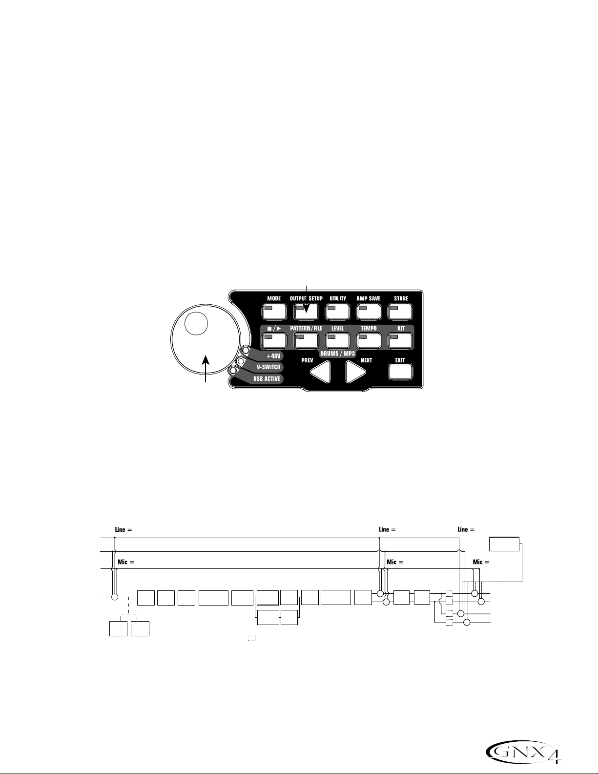
Select an Output Setup Mode
1.Press the OUTPUT SETUP button located in the control panel to the right of the D A T A WHEEL.
2.Rotate the DATA WHEEL to select an Output Setup mode .
3.Select the Output Setup mode that applies to your application,they include:
SteroAll,Mono All,
Mono 1/4, Mono XLR,Split 1 and Split 2.
Note: See page 9 for a detailed explanation of the Output Setups.
5.Press the EXIT button located in the control panel.
Select a Preset
The GNX4 comes with 80 pre-programmed Factory Presets,and 80 User Presets. From the factory,the
User Presets are exact duplicates of the Factory Presets.
1.Press the UP/DOWN footswitches to select a Bank.
2.Press Footswitches 1-5 to select a preset, or rotate the D A T A WHEEL.
2
Introduction
Page 13

A Guided Tour of the GNX4
The Front Panel
1. Footswitches 1-5
Depending on the selected mode, these 5 footswitches select presets,change amp channels, turn
individual effects on and off,control drum machine operations, control playback of MP3 files,and give you
hands-free operation of the GNX4’s onboard recorder. Drums/MP3, Bypass,Tuner, Mode , and Pattern/File
functions are accessed by pressing the labeled pair of footswitches.
2. Recorder Control and USB/Signal Routing Panel
This control panel operates the GNX4’s onboard digital recorder,USB audio routing, and mass storage
functions. (See page 68 for more details regarding the Recorder Control and USB/Signal Routing
Panel.)
3. Record/Play Level Meters
These 4 Segment LED Meters allow you to monitor the Record/Play signal levels during use.
4. Effect Select Buttons
The Effect Select buttons are used together with the Matrix LEDs to choose the effects you want to edit.
5.Amp Control Buttons
The Amp Control buttons are used to select one of the amp/cabinet model edit rows including:
CHAN ONE EQ (Green),GENETX (Yellow),CHAN TWO EQ (Red), and TONE (Silver)
6. Status Button
The Status button is used to select amp channels for editing purposes and to turn each respective amp
channel’s EQ on and off. With the CHAN ONE EQ (Green) amp/cabinet model edit row selected,the
Status button turns Channel One’s EQ on and off. With the GENETX (Yellow) amp/cabinet model edit
row selected,the Status button selects between the Channel One, Channel Two,and the Warp Channels
(if a Warped state between both channels exists). With the CHAN TWO EQ (Red) amp/cabinet model
3
Introduction
37 98111213
2 10
564
a
b
CONTROL A CONTROL B CONTROL C
1
TAP TEMPOAMP CHANNEL
14
15
Page 14

edit row selected,the Status button turns Channel Two’s EQ on and off. With the TONE (Silver) edit row
selected,the Status button selects between Channel One Amp, Warped Amp,and Channel Two Amp. The
Amp Gain,Bass, Midrange,Treble,and Amp Levels alternate between editing Channel One’s (lit green) or
Channel T w o’s (lit red) amp settings as the status button is pressed. When editing effects in the Effect
Matrix,the Status Button turns the selected effect on and off, or selects a controller type for the
expression assignment.
7. Knobs
Depending on which amp control row or effect row is selected using the Amp Control or Effect
Select buttons, these 5 knobs adjust the parameters listed in the column directly above or below each
knob.
8. Matrix
a. GeNetX
™
Amp Controls Matrix
The GeNetX Amp Controls Matrix displays the GNX4’s Channel One and Channel Two amp types,
cabinet types,EQ/tone controls, and cabinet tuning parameters available for editing in each preset.
b.Effects Matrix
The Effects Matrix displays the effects parameters available for editing in each preset.
9. Displays
The Displays give feedback of the various functions that are being used in the GNX4,including preset
name, editing functions,tuner,utility menus, drum machine and recorder settings.
10. Preset Bank LEDs
The Preset Bank LEDs indicate whether the selected preset is an internal Factory or User preset,or if
the preset is a user preset saved externally on the optional Compact Flash memory card.
11. Data Wheel
The Data Wheel is a multi-function control used for selecting presets,editing preset parameters or for
adjusting the settings of the Recorder, Drum Machine, Utility,and Output Setup menus.
12. Status Indicator LEDs (+48V,V-Switch, and USB Active)
The Status Indicator LEDs illuminate when the Microphone Input has +48V Phantom Power active,the
Expression Pedal’s V-Switch is engaged,or the USB connection is active.
13. Control Panel Buttons
The Control Panel Buttons are used to select the GNX4’s Footswitch Modes, Output Setups,Utility
functions,and to store Amp/Cabinet Model edits and Preset changes. They also access the GNX4’s
onboard General MIDI Drum Machine and MP3 Player. The buttons are labeled as follows:
MODE - This button changes the functionality of footswitches 1-5 (see the Footswitch Functions
for Modes section on page 59). When the Mode button is lit yellow,footswitches 1-5
toggle effects on and off,change amp channels, or can be assigned to various parameters
using the control footswitches. When the Mode button is lit green, footswitches 1-5 select
presets in the current preset bank. When the Mode button is lit red, footswitches 1-5
control the GNX4’s recorder functions.
4
Introduction
Page 15

OUTPUT SETUP - This button selects one of the GNX4 Output Setups: Stereo All, Mono All,
Mono 1/4”,Mono XLR, Split 1 and Split 2. Stereo and Mono All have all the
input sources (guitar, mic, line, drums, onboard recorder playback and audio
playback from USB) routed to both output pairs in either stereo or mono
respectively. Split 1 routes the guitar signal to just the 1/4” outputs while all
other sources are routed out the XLR outputs. Split 2 is the same as Split 1
but the guitar signal is also routed out the XLR outputs.
UTILITY - This button accesses the GNX4’s global functions including:Volume Pedal Update,
V-Switch Threshold/Sensitivity,Expression Pedal Calibration,Preset Bounceback, HandsFree,Bank Naming, MIDI Channel selection, Sysex Bulk Dump,MIDI Preset Dump,User
HyperModel
™
Amp Dump,MIDI Mapping,MIDI Merge , Drum MIDI, Default Drum Kit,and
Factory Reset (see the Utilities section on page 104).
AMP SAVE - This button stores Amp and Cabinet changes (tone, gain,level, amp type, cabinet type,
warp,or cabinet tuning) as HyperModels.
STORE - This button is used to save Preset edits to the GNX4’s User Presets or to an optional
Compact Flash card.
(STOP/PLAY) -This button is used to turn the GNX4’s General MIDI Drum Machine/MP3
Player on and off.
PATTERN/FILE - Pressing this button and using the DA TA WHEEL selects the GNX4’s internal
drum patterns,external MIDI, or MP3 files to be played. MIDI and MP3 files must
be resident in the GNX4>MIDI and GNX>MP3 directories on your Compact
Flash card in order for them to be recognized (see the Memory
Card/Computer File Format section on page 103).
LEVEL - This button adjusts the GNX4’s Drum Machine output level or the playback level of MP3s.
TEMPO - This button adjusts the tempo of the GNX4’s Drum Machine. Tempo is ignored when an
MP3 is selected.
KIT - This button selects one of the GNX4’s drum kits. Kit is ignored when an MP3 is selected.
EXIT - Exits all functions back to the preset display.
14. Down/Up Footswitches
These footswitches select songs (Recorder Mode),move up and down through the User preset banks
(Preset Mode),and navigate through presets (Stompbox/Control Mode). Pressing and holding these
footswitches simultaneously temporarily enables them to select the GNX4’s drum patterns or any MIDI
and MP3 files available on an optional Compact Flash memory card.
15. Expression Pedal
The Expression Pedal controls effect parameters in real time. Most GNX4 parameters can be assigned to
the Expression Pedal. Applying extra pressure to the toe of the Expression Pedal enables the V-Switch
feature which changes the Expression Pedal’s function to control the Wah (see V-Switch
Threshold/Sensitivity on page 104).
5
Introduction
Page 16
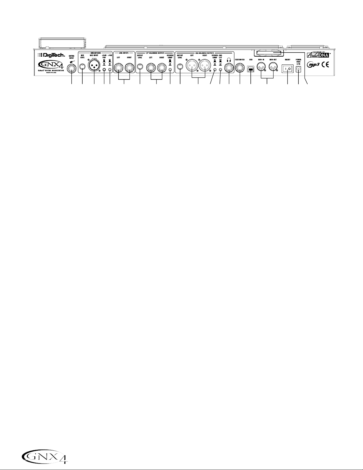
The Rear Panel
1. Guitar/Instrument Input
Connect your guitar/instrument to this jack.
2. Mic Level
Controls the gain of the mic input preamp.
3. Microphone Input
Connect a low impedance microphone to this jack for recording vocals or acoustic instruments into the
GNX4’s Recorder. It can also be used for the Talker
™
Vocoder effect (see Talker on page 37). The mic
signal can remain dry or processed through the GNX4’s effects for live and recording applications.
4. -20dB Pad Switch
The -20dB pad is a resistive attenuator that drops the level coming from the mic input jack. Its purpose
is to give you a way of preventing overload of the preamp when incoming signals become excessive.
When the pad is on,the net gain of the preamp is 20dB lower than normal.
5. +48V Phantom Power Switch
This switches on the phantom power to the Microphone Input. Dynamic microphones do not require
phantom power to operate,but are not harmed by it. Most condenser microphones do require phantom
power to operate. If you are unsure about the phantom power requirements for your microphone,
consult your microphone’s documentation or contact the manufacturer.
6. Left/Right Balanced Line Inputs
Connect line level sources to these jacks for recording or live performance mixing into the GNX4. Line
signals can remain dry or be processed through the GNX4’s effects for live and recording applications.
7. Output Level (1/4” Outputs Only)
Controls the overall volume level of the 1/4” outputs of the GNX4.
8. Left/Right Line 1/4” Balanced Outputs
Connect these outputs to your guitar amplifier(s),power amplifier(s),or to a mixing console that accepts
1/4” balanced connections.
9. Speaker Compensation Switch (1/4” Outputs Only)
This switch enables Speaker Compensation on the 1/4” Outputs for when they are connected to a
full-range speaker system. This switch should be set to the off position when the 1/4” outputs are
connected to a guitar amp or power amp/guitar cabinet system.
10. Output Level (XLR and Headphone Outputs Only)
Controls the overall volume level of the balanced XLR and Headphone outputs of the GNX4.
6
Introduction
12345 6 7 981011121314151617182019
Page 17

11. Left/Right XLR Balanced Outputs
Connect these outputs to your power amplifier/speaker system or to a mixing console that accepts XLR
balanced connections.
12. Speaker Compensation Switch (XLR and Headphone Outputs Only)
This switch enables Speaker Compensation on the XLR and Headphone Outputs for when they are
connected to a full-range speaker system. This switch should be set to the off position when the XLR
outputs are connected to a power amp/guitar cabinet system.
13. Ground Lift Switch
This switch lifts pin 1 of the XLR Outputs from all ground references. This may be necessary to break
troublesome ground loops that can cause hum in the system,especially when both XLR and 1/4” outputs
are used together.
14. Headphone Output
Connect a pair of stereo headphones to this jack. Do not connect a mono plug to this jack, as it may
damage the output driver.
15. Footswitch
(Optional ) Connect a GNXFC footswitch to this jack for remote control of the GNX4’s recorder
functions.
16. USB Jack
Connect this jack to your computer’s USB port for hard disk recording and computer preset editing via
the X-Edit
™
Editor/Librarian software. A standard USB cable is included. The GNX4 is compatible with
USB 2.0 high speed ports, however the USB 2.0 bus will switch to a USB v1.1 full speed data rate to
work with the GNX4.
ATTENTION: Before using the GNX4’s USB connection,it is necessary to first install
the USB drivers provided on the X-Edit Software CD. Please read the Software
Installation Guide that came with your GNX4 for the proper instructions on how to
install the drivers for your operating system.
17. MIDI In
The MIDI In jack receives all incoming MIDI data. MIDI preset changes and CC control messages
received from external MIDI devices connected to the MIDI In jack can be used to control the GNX4
and its presets parameters. When the GNX4 is connected to the computer via USB, the MIDI In can be
used as a MIDI interface for recording any MIDI data in Pro Tracks Plus
™
or other MIDI recording
software.
18. MIDI Out/Thru
The MIDI Out/Thru jack sends MIDI data from the GNX4 including system exclusive information and
MIDI preset changes. When the GNX4 is connected to the computer via USB, it can act as a MIDI
interface for sending MIDI data from Pro Tracks Plus
™
or other MIDI recording software to external
keyboards or sound modules. When MIDI Merge is enabled in the Utility menu,the MIDI Out acts as a
MIDI Thru for any data coming into the GNX4 from the MIDI In jack.
19. Power Switch
Turns the power on and off.
7
Introduction
Page 18

20. Power Input
Connect only the provided DigiTech PSS3 power supply to this jack.
21. Compact Flash Memor y Card Slot
(Optional ) Insert an optional Compact Flash (CF) card in this slot for use with the GNX4’s on board
recorder. Songs,Presets, MIDI files, and MP3 files can be saved and retrieved from the CF card as well.
The GNX4 can also function as a Compact Flash card reader by using a Compact Flash card (inserted
into this slot) and connecting the GNX4 to your computer via the USB port. The Compact Flash card
will be recognized as a hard disk (mass storage drive) for transferring files. See Compact Flash
Storage/File T ransfer on page 102 for more information regarding this function.
NOTE: The GNX4 is compatible with Type I Compact Flash cards only. It is not compatible
with Type II cards or IBM/Hitachi Microdrives
™
.
8
Introduction
Page 19
Setups Introduction
The GNX4 is equipped with four inputs and four outputs that can be configured several different ways for
both live and recording applications. These settings determine which pair of outputs the mic , line, and guitar
processing are routed to and how the mic or line inputs are routed through the GNX4’s effects
processing.
Output Setups and Speaker Compensation
The GNX4 features both 1/4” and XLR outputs on the rear panel. These jacks let you simultaneously
connect the GNX4 to an amplifier/speaker system on stage via the 1/4” outputs and connect directly to
your PA system via the XLR outputs. The GNX4 incorporates Speaker Compensation filtering that can
be turned on or off independently for each output pair depending on your application needs.
Use the OUTPUT SETUP button along with the DA TA WHEEL to select one of the Output Setup
options.
The six Output Setups are as follows:
steroall - All input sources (guitar, mic, line, drums, onboard 8-track recorder playback and USB
playback) are routed to both output pairs in stereo. Speaker Compensation can be turned
on and off independently for either the 1/4" or XLR outputs using the Speaker
Compensation switch associated with each pair on the rear panel.
9
Audio Routing Setups
Output Setup button
Data Wheel
Control Panel
Line Left
Line Right
Mic Input
Guitar Input
+
Comp
Detector
line fx
mic fx
Pickup
Sim
Gate
Detector
Wah Comp
Whammy/IPS
(except
Talker)
CH 1 Amp
CH 1 Amp
CH 1
Stompbox
SC
CH 1
Modeling/
Modeling/
Cabinet
Cabinet
Tone
Tone
CH 2 Amp
CH 2
Modeling/
Cabinet
Tone
= Speaker Compensation Module
Gate
Whammy/IPS
(Talker)
Chorus/
Mod
line rvb
mic rvb mic dry
+
+
Delay Reverb
SC
SC
SC
SC
+
+
+
line dry
DRUMS,
RECORDER,
USB PLAYBACK
XLR Left Output
XLR Right Output
+
1/4" Left Output
1/4" Right Output
Page 20
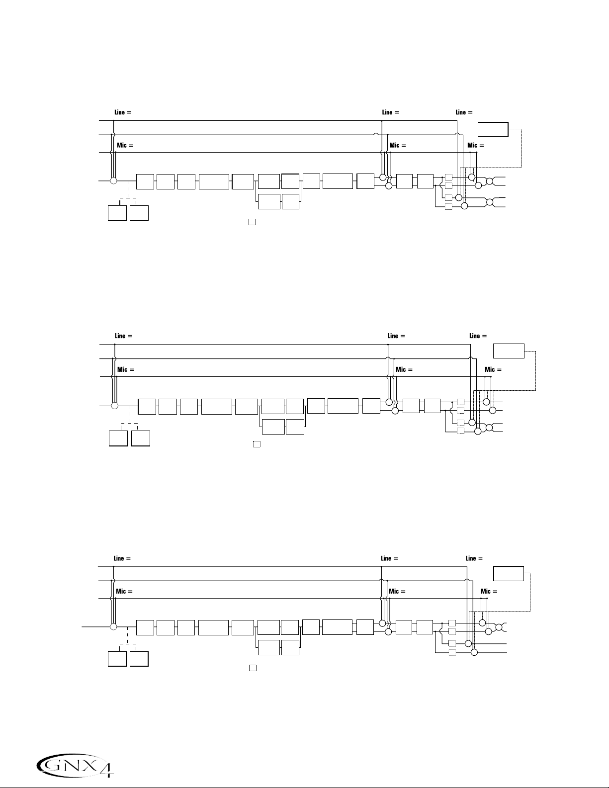
mono all - All input sources (guitar, mic, line, drums, onboard 8-track recorder playback and USB
playback) are routed to both output pairs in mono. Speaker Compensation can be turned
on and off independently for either the 1/4" or XLR outputs using the Speaker
Compensation switch associated with each pair on the rear panel.
mono 1/4 - All input sources (guitar, mic, line, drums, onboard 8-track recorder playback and USB
playback) are routed to the 1/4” outputs in mono. All input sources routed to the XLR
outputs maintain stereo separation. Speaker Compensation can be turned on and off
independently for either the 1/4" or XLR outputs using the Speaker Compensation switch
associated with each pair on the rear panel.
mono xlr - All input sources (guitar, mic, line, drums, onboard 8-track recorder playback and USB
playback) are routed to the XLR outputs in mono. All input sources routed to the 1/4”
outputs maintain stereo separation. Speaker Compensation can be turned on and off
independently for either the 1/4" or XLR outputs using the Speaker Compensation switch
associated with each pair on the rear panel.
10
Audio Routing Setups
Line Left
Line Right
Mic Input
Guitar Input
+
Comp
Detector
line fx
mic fx
Pickup
Sim
Gate
Detector
Wah Comp
Whammy/IPS
(except
Talker)
CH 1 Amp
CH 1 Amp
CH 1
Stompbox
SC
CH 1
Modeling/
Modeling/
Cabinet
Cabinet
Tone
Tone
CH 2 Amp
CH 2
Modeling/
Cabinet
Tone
= Speaker Compensation Module
Gate
Whammy/IPS
(Talker)
Chorus/
Mod
line rvb
mic rvb mic dry
+
+
Delay Reverb
SC
SC
SC
SC
+
+
+
line dry
DRUMS,
RECORDER,
USB PLAYBACK
+
+
+
XLR Left Output
XLR Right Output
1/4" Left Output
1/4" Right Output
Line Left
Line Right
Mic Input
Guitar Input
+
Comp
Detector
line fx
mic fx
Pickup
Sim
Gate
Detector
Wah Comp
Whammy/IPS
(except
Talk er)
CH 1 Amp
CH 1 Amp
CH 1
Stompbox
SC
CH 1
Modeling/
Modeling/
Cabinet
Cabinet
Tone
Tone
CH 2 Amp
CH 2
Modeling/
Cabinet
Tone
= Speaker Compensation Module
Gate
Whammy/IPS
(Talker)
Chorus/
Mod
line rvb
mic rvb mic dry
+
+
Delay Reverb
SC
SC
SC
SC
+
+
+
line dry
USB PLAYBACK
+
+
DRUMS,
RECORDER,
XLR Left Output
XLR Right Output
1/4" Left Output
1/4" Right Output
Line Left
Line Right
Mic Input
Guitar Input
+
Comp
Detector
line fx
mic fx
Pickup
Sim
Gate
Detector
Wah Comp
Whammy/IPS
(except
Tal ke r)
CH 1 Amp
CH 1 Amp
CH 1
Stompbox
SC
CH 1
Modeling/
Modeling/
Cabinet
Cabinet
Tone
Tone
CH 2 Amp
CH 2
Modeling/
Cabinet
Tone
= Speaker Compensation Module
Gate
Whammy/IPS
(Talker)
Chorus/
Mod
line rvb
mic rvb mic dry
+
+
Delay Reverb
SC
SC
SC
SC
+
+
+
line dry
DRUMS,
RECORDER,
USB PLAYBACK
XLR Left Output
+
XLR Right Output
+
1/4" Left Output
1/4" Right Output
Page 21

The SPLIT1 Output mode routes guitar signal to the 1/4” outputs while the mic, line input sources,
drums,and audio playback from the onboard 8-track recorder and the computer are routed out the XLR
outputs.
SPLIT2 is the same as SPLIT1 but the guitar signal with Speaker Compensation is also routed
out the XLR outputs.
SPLIT1 - Stereo guitar processing is routed to the 1/4” outputs. Audio playback from the computer, mic ,
and line sources are routed to the XLR outputs. Speaker Compensation can be individually
turned on and off either the 1/4” or XLR outputs using the Speaker Compensation switch
located next to each output pair on the rear panel.
SPLIT2 - Stereo guitar processing is routed to the 1/4” outputs without Speaker Compensation. Stereo
guitar processing,audio playback from the computer, mic, and line sources are routed to the
XLR outputs with Speaker Compensation. Speaker Compensation can be individually turned
on and off either the 1/4” or XLR outputs using the Speaker Compensation switch located
next to each output pair on the rear panel.
11
Audio Routing Setups
Line Left
Line Right
Mic Input
Guitar Input
line fx
mic fx
CH 1 Amp
Whammy/IPS
(except
Talker)
SC
Comp
Pickup
Gate
Detector
Sim
Wah Comp
+
Detector
CH 1 Amp
CH 1
Stompbox
Modeling/
Modeling/
Tone
Tone
CH 2 Amp
Modeling/
Ton e
CH 1
Cabinet
Cabinet
CH 2
Cabinet
Gate
Whammy/IPS
= Speaker Compensation Module
(Talker)
Chorus/
Mod
line rvb
mic rvb mic dry
+
Delay Reverb
+
SC
SC
+
line dry
DRUMS,
RECORDER,
USB PLAYBACK
XLR Left Output
XLR Right Output
+
1/4" Left Output
1/4" Right Output
Line Left
Line Right
Mic Input
Guitar Input
line fx
mic fx
CH 1 Amp
Whammy/IPS
(except
Talker)
SC
Comp
Pickup
Gate
Detector
Sim
Wah Comp
+
Detector
CH 1 Amp
CH 1
Stompbox
Modeling/
Modeling/
Ton e
Ton e
CH 2 Amp
Modeling/
Tone
CH 1
Cabinet
Cabinet
CH 2
Cabinet
Gate
Whammy/IPS
= Speaker Compensation Module
(Talker)
Chorus/
Mod
line rvb
mic rvb mic dry
+
Delay Reverb
+ +
SC
SC
SC
SC
line dry
+
DRUMS,
RECORDER,
USB PLAYBACK
XLR Left Output
XLR Right Output
1/4" Left Output
1/4" Right Output
Page 22

Mic and Line Setups
The Mic and Line Setups are configurations for the mic and line inputs designed for both live performance
and recording applications. The GNX4 acts as a mixing device for mic and line sources,and can eliminate
the need for a mixer when the GNX4’s outputs are to be plugged directly into a full-range powered
speaker system. When enabled,these inputs can be routed around or through the GNX4’s effects
processing and then mixed directly into the GNX4’s 1/4” and XLR outputs.
Use the SHIFT>MIC and SHIFT>LINE buttons along with the D A T A WHEEL to select the Mic/Line
Setup options.
Both Mic and Line inputs have four settings that can be independently selected. They are as follows:
MIC OFF / LINe OFF - Mic and Line inputs are disabled.
MIC DRY / LINe DRY - Inputs routed directly to GNX4’s outputs, bypassing all effects processing.
MIC RVB / LINe RVB - Inputs routed through delay and reverb effects of the current preset.
MIC FX / LINE FX - Inputs routed through all effects of current preset.
Mic Routing
Line Input Routing
off
off
12
Audio Routing Setups
Mic, Line
buttons
Shift button
Recorder Panel
Data Wheel
mic
Mic Input
Pickup
Sim
mic fx
Wah Comp
Whammy/IPS
(except
Talker)
Stompbox
CH 1 Amp
CH 1 Amp
Modeling/
Modeling/
Tone
Tone
CH 2 Amp
Modeling/
Tone
CH 1
CH 1
Cabinet
Cabinet
CH 2
Cabinet
Gate
Whammy/IPS
(Talker)
mic rvb mic dry
Chorus/
Mod
+
+
Delay Reverb
SC
SC
SC
SC
+
+
XLR Left Output
XLR Right Output
1/4" Left Output
1/4" Right Output
+
+
Line Left
Line Right
line
+
line fx
Pickup
Sim
Wah Comp
Whammy/IPS
(except
Tal ker )
Stompbox
CH 1 Amp
CH 1 Amp
Modeling/
Modeling/
Ton e
Ton e
CH 2 Amp
Modeling/
Ton e
CH 1
CH 1
Cabinet
Cabinet
CH 2
Cabinet
Gate
Whammy/IPS
(Talker)
Chorus/
Mod
line rvb
+
+
Delay Reverb
line dry
SC
+
SC
+
SC
+
SC
+
XLR Left Output
XLR Right Output
1/4" Left Output
SC
SC
SC
1/4" Right Output
Page 23

Optimizing the Mic Input Level
To adjust the microphone input level for optimal use, you must first setup the GNX4’s Record Level
meter located on the Recorder Control and USB/Signal Routing Panel to monitor the live microphone
signal. To do this, follow these steps:
1.Press the SHIFT button located on the Recorder Control and USB/Signal Routing Panel and then
press the CF/USB 1-2 SRC button.
2. Then use the DA T A WHEEL to select your desired input routing source (
STEREOfx,STEROALL,
MONO fx, MONO ALL,SUM+DGTR, SUM+MIC, DGTR+MIC,or DRY MIC). STEREOfx and mono fx will
only work if the Mic Input is selected properly. (See page 64 for more information regarding the
GNX4 Input Sources.) Also, if the mic is routed through
MIC RVB or MIC FX,the active effect’s
level can impact the levels shown in the meters.
3. Talk or sing into the mic as intended for use and adjust the GNX4’s Microphone Input Level knob
located on the rear panel until the level consistently lights just below the 0 dB clip point on the REC
LEVEL meter. Utilize the -20 dB pad switch also located on the GNX4’s rear panel if the level is too
high to provide proper headroom.
NOTE: If your microphone requires phantom power,first make sure the microphone is
connected, then press the Phantom Power switch (labeled +48V) located on the rear panel
of the GNX4. The +48V LED located next to the DATA WHEEL indicates the phantom
power is active. If your mics don’t need phantom power, it is best to turn it off.
Optimizing the Line Input Levels
To adjust the line input levels for optimal use,you must first setup the GNX4’s Record Level meter
located on the Recorder Control and USB/Signal Routing Panel to monitor the live line input signals. To
do this,follow these steps:
1.Press the SHIFT button located on the Recorder Control and USB/Signal Routing Panel and then
press the CF/USB 1-2 SRC button.
2. Then use the DA T A WHEEL to select your desired input routing source (
STEREOfx,STEROALL,
MONO fx, MONO ALL,SUM+DGTR, or DRY line). STEREOfx and mono fx will only work if the Line
Inputs are selected properly. (See page 64 for more information regarding the GNX4 Input
Sources.) Also, if the lines are routed through
line RVB or line FX,the active effect’s level can
impact the levels shown in the meters.
3.Play audio back from your external audio device (mixer, keyboard,CD player, etc.) and adjust its output
level until the level consistently lights just below the 0 dB clip point on the GNX4’s REC LEVEL meter.
13
Audio Routing Setups
Page 24
For Live Performance
The GNX4 was designed to be extremely flexible to meet any of your application needs. For many GNX4
users,its primar y purpose will be for use in live performances. Whether you are a solo performer who
spends weekends playing at a small club or the power-user playing the largest venues each night,the GNX4
has just what you need to do the gig right. The following diagrams show examples of how to utilize the
GNX4 in typical live performance applications.
Before connecting the GNX4,make sure both the GNX4 and your amplifier(s) are turned OFF.
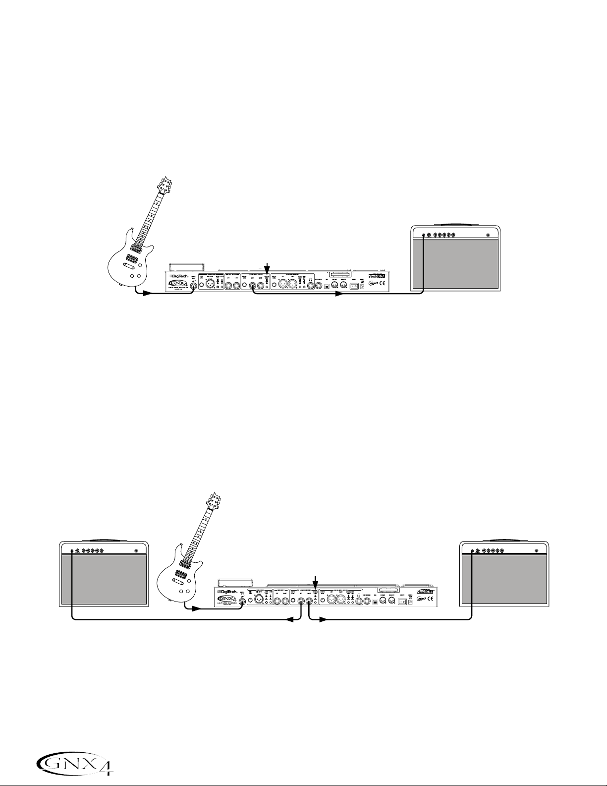
Small Club Setup (Mono Amp Rig)
This diagram demonstrates a minimum setup for using the GNX4 in a typical,small club performance
setup. All you need is your guitar, a couple of guitar cables, and an amp. This connection scheme also
applies for use with a power amp/speaker cabinet rig.
1.Connect your guitar to the GNX4’s Guitar Input.
2.Connect a single mono instrument cable from the Left 1/4” Balanced Output of the GNX4 to the
instrument input or the effect return on your amplifier.
3.Switch the GNX4’s Speaker Compensation for the 1/4” Balanced Outputs to the OFF position.
4.Press the GNX4’s Output Setup button and select “
MONO 1/4” mode using the Data Wheel.
NOTE: When using a guitar amp(s), it may be best to connect the GNX4’s Output to your
amp’s effects return to avoid coloration of the tone due to the amplifier’s tone controls.
Medium Stage Setup (Stereo Amp Rig)
Whether your gig is at a large club or a small hall,nothing beats running your guitar in stereo. This
diagram demonstrates a typical setup using your GNX4’s line outputs,and two guitar combo amps.
1.Connect your guitar to the GNX4’s Guitar Input.
2.Connect mono instrument cables from the Left and Right 1/4” Balanced Outputs of the GNX4 to the
instrument inputs or the effect returns on your amplifiers.
3.Switch the GNX4’s Speaker Compensation for the 1/4” Balanced Outputs to the OFF position.
4.Press the GNX4’s Output Setup button and select “
STEROAll” mode using the Data Wheel.
14
Making Connections
Amplifier
Guitar
Speaker Compensation Switch (1/4" Outputs)
Guitar Input
Left 1/4" Balanced Output
Amplifier
Guitar
Speaker Compensation Switch (1/4" Outputs)
Amplifier
Guitar Input
1/4" Balanced Outputs
Page 25
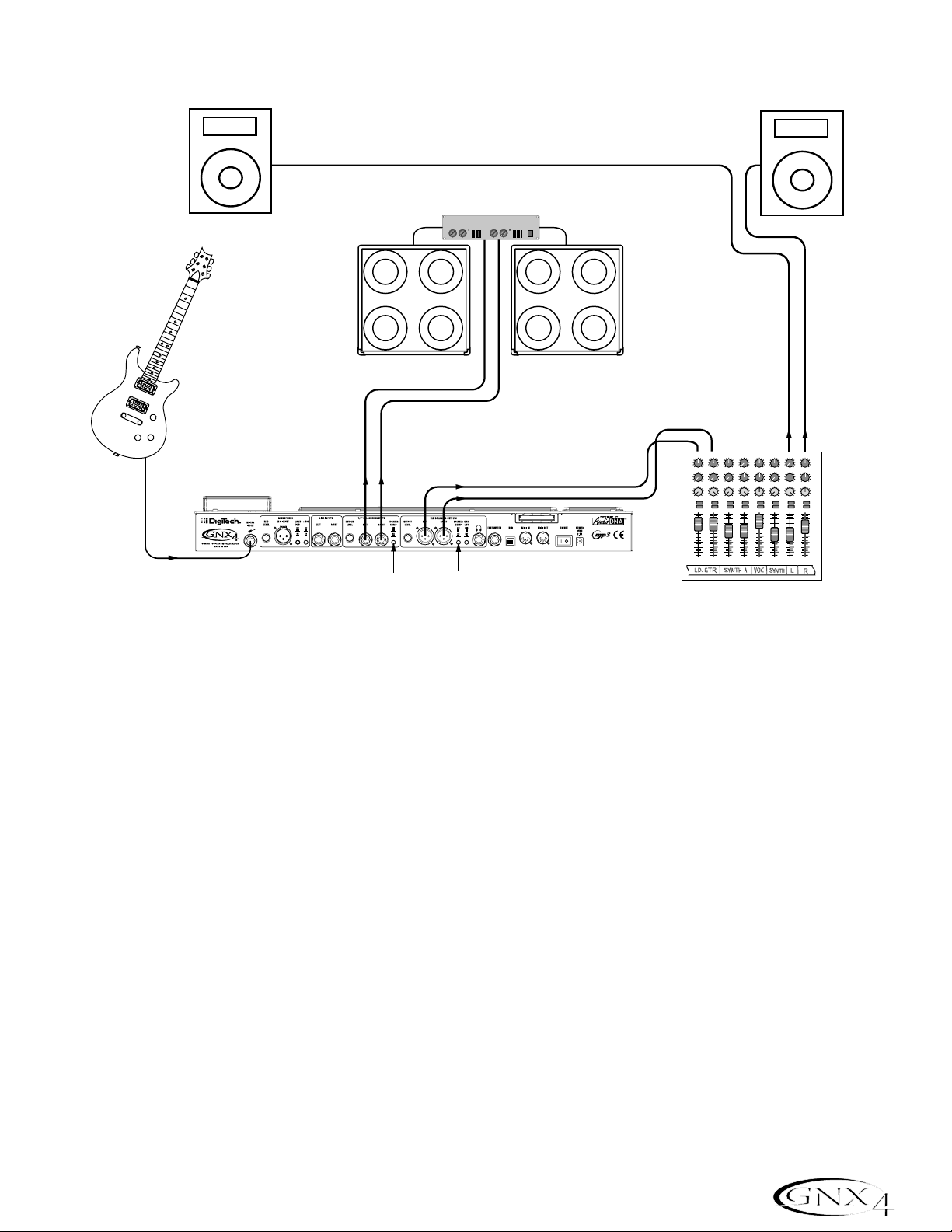
Large Stage Setup (Stereo Amp/Cabinet Rig)
A large stage rig lets you really pull out all the stops since space isn’t necessarily an issue,but volume
usually is. For this application, plug your guitar into the GNX4 and connect mono instrument cables from
the GNX4’s 1/4” outputs into a stereo power amp feeding two cabinets. Using two cabinets gives you
much more dramatic stereo separation and helps widen the sweet spot for your sound when you move
onstage. Another great idea is to run the GNX4’s XLR outputs directly into the house P.A.and have the
sound engineer control your front of house volume in the overall mix. Then if you need to turn up your
stage volume,you won’t upset him by trying to rebalance your guitar volume in the house mix. This
diagram demonstrates a typical,large stage performance setup.
1.Connect your guitar to the GNX4’s Guitar Input.
2.Connect mono instrument cables from the GNX4’s Left and Right 1/4” Line Outputs to a stereo
power amplifier amplifier and switch the 1/4” Outputs Speaker Compensation to the OFF position.
3.Connect XLR cables from the GNX4’s Left and Right XLR outputs to the house P.A. mixer and switch
the XLR Outputs Speaker Compensation to the ON position.
4.Press the GNX4’s OUTPUT SETUP button and select “
STEROALL“ as the output mode using the
DAT A WHEEL.
15
Making Connections
PA Speaker (Left)
Guitar
Guitar Input
1/4" Balanced
Outputs
Speaker Compensation
Switch (1/4" Outputs)
Stereo Power Amp
2- Speaker Cabs
XLR Balanced Outputs
Speaker Compensation
Switch (XLR Outputs)
46
46
2
2
8
0
0
10
10
Aux 1
Aux 1
2468
2468
0
10
0
10
Aux 2
Aux 2
-10+1
-10+1
-2
+2
-2
+2
-3
+3
-3
-4
+4
-4
-5
-5
+5
+5
Pan
Pan
Mute
Mute
L / R
L / R
+10
+10
+5
+5
0
0
-5
-5
-10
-10
-20
-20
-30
-30
-∞
-∞
1234
PA Speaker (Right)
46
2
8
0
Aux 1
2468
0
Aux 2
-10+1
-2
+3
-3
+4
-4
-5
Pan
Mute
L / R
+10
+5
0
-5
-10
-20
-30
-∞
Mixer
46
2
2
8
8
0
10
10
Aux 1
2468
2468
0
10
10
Aux 2
-10+1
+2
-2
+2
-2
+3
-3
+3
-3
+4
-4
+4
-4
-5
-5
+5
+5
Pan
Mute
Mute
L / R
L / R
+10
+10
+5
+5
0
0
-5
-5
-10
-10
-20
-20
-30
-30
-∞
-∞
0
0
46
46
46
46
2
2
2
8
8
8
0
0
0
10
10
10
Aux 1
Aux 1
Aux 1
Aux 1
2468
2468
2468
0
0
10
0
10
10
Aux 2
Aux 2
Aux 2
Aux 2
-10+1
-10+1
-10+1
-10+1
+2
-2
+2
-2
+2
-2
+3
-3
+3
-3
+3
-3
+4
-4
+4
-4
+4
-4
-5
-5
-5
+5
+5
+5
Pan
Pan
Pan
Pan
Mute
Mute
Mute
L / R
L / R
L / R
+10
+10
+10
+5
+5
+5
0
0
0
-5
-5
-5
-10
-10
-10
-20
-20
-20
-30
-30
-30
-∞
-∞
-∞
5
6
8
10
10
+2
+3
+4
+5
Page 26
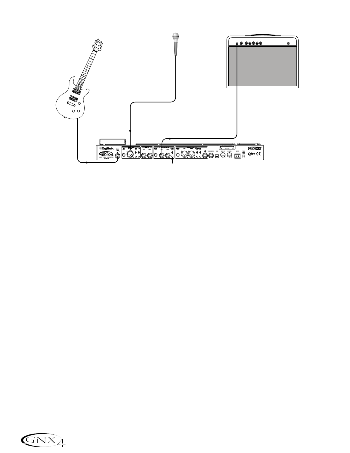
Talker™Performance Setup
The GNX4’s built-in Talker effect creates a talk box effect. To create this effect you must plug a
microphone into the GNX4’s mic input and select one of the five Talker types in the Whammy™/IPS/Talk
module of a preset. Then as you play your guitar talk into the microphone to emulate the talk box effect.
The Talker can be used with any output setup,but for this diagram it will be shown in conjunction with a
mono amp rig.
1.Connect your guitar to the GNX4’s Guitar Input.
2.Connect a single mono instrument cable from the Left 1/4” Line Output of the GNX4 to the
instrument input or the effect return on your amplifier and switch the 1/4” Balanced Outputs Speaker
Compensation to the OFF position.
3.Connect a microphone to the GNX4’s Mic Input using an XLR cable.
4.Select one of the five Talker types in the Whammy/IPS/Talk module of a preset.
5.Press the GNX4’s OUTPUT SETUP button and select “
MONO 1/4“ as the output mode using the
DAT A WHEEL.
6.Use the Mic Level control knob located next to the Mic Input on the GNX4’s rear panel to adjust the
microphone output level. To adjust your microphone input level for optimal use see Optimizing the
Mic Input Level on page 13.
16
Making Connections
Guitar
Microphone
Input
Microphone
Amplifier
Left 1/4" Balanced Output
Guitar Input
Speaker Compensation Switch (1/4" Outputs)
Page 27

Coffee House/Solo Performance Setup
As a solo performer, we all know how important it is to minimize the amount of gear we have to cart to
a gig. For the more elaborate system, this may include electronic keyboards, a CD player,and a mixer.
The GNX4 virtually eliminates the need for most of this hardware. First, for your backing tracks,just rip
your CD audio tracks into MP3s and place these in the MP3 folder created by the GNX4 on the compact
flash card. If you need a mic for vocals or an acoustic instrument,just plug it into the GNX4’s mic input.
You have a variety of routings you can select from including taking advantage of the GNX4’s effects
processing. For the more advanced setup or if you have a partner on keyboards,just plug them into the
GNX4’s line inputs and select the appropriate routing needed. Everything can now be run out the
GNX4’s XLR outputs directly into powered speakers. You can even run to a floor monitor out one of
the available 1/4” Line Outputs and enable Speaker Compensation on both pairs of outputs.
1.Connect your guitar to the GNX4’s Guitar Input.
2.Connect a microphone to the GNX4’s XLR Mic Input use the Mic Level control knob located next to
the Mic Input on the GNX4’s rear panel to adjust the microphone output level. To adjust your
microphone input level for optimal use see Optimizing the Mic Input Level on page 13.
3.Connect a mono instrument cable from the GNX4’s Left 1/4” Line Output to a powered monitor.
4.Connect the GNX4’s balanced XLR Left and Right Outputs to a pair of powered PA speakers.
5.Switch the Speaker Compensation on for both the XLR and 1/4” outputs.
6.Press the GNX4’s OUTPUT SETUP button and select “
STEROALL” as the output mode using the
DAT A WHEEL.
7.Use the Mic Level control knob located next to the Mic Input on the GNX4’s rear panel to adjust the
microphone output level. To adjust your microphone input level for optimal use see Optimizing the
Mic Input Level on page 13.
17
Making Connections
PA Speaker (Left)
Microphone
Guitar
Guitar Input
Mic Input
XLR Balanced Outputs
Powered Monitor
Left 1/4"
Output
CF Card
CompactFlash
Speaker Compensation
Switch (XLR Outputs)
PA Speaker (Right)
®
256 MB
Page 28

For Recording
The GNX4 also offers great flexibility for recording applications. Listed below are a couple typical recording
setups.
Onboard Recorder Application
Ever had a moment where the band just clicked with a great song idea? Then you came back the next
night to go over it again and….how did that go? Never again thanks to the GNX4’s onboard recorder
and its ability to remotely capture that idea forever. Just plug a mic into the GNX4’s mic input, or if you
have multiple mics and a mixer, use the stereo output of the mixer into the GNX4’s Line Inputs. Use the
Shift>CF/USB 1-2 Source buttons located on the GNX4’s Recorder Panel to set the output routing to
“
STEROALl“ and hit record. Now you can ensure that spontaneous genius will never be lost again.
1.Connect your guitar to GNX4’s Guitar Input.
2.Connect a microphone to the GNX4’s Mic Input and use the Mic Level control knob located next to
the Mic Input on the GNX4’s rear panel to adjust the microphone output level. To adjust your
microphone input level for optimal use see Optimizing the Mic Input Level on page 13.
3.Connect a single mono instrument cable from the GNX4’s Left 1/4” Balanced Output to the
instrument input or the effect return on your amplifier and switch the 1/4” Balanced Outputs Speaker
Compensation to the OFF position.
4.Connect a pair of stereo headphones to the Headphone Output.
5.(Advanced Setup) Connect microphones and a keyboard to your mixer and connect the mixer’s stereo
outputs to the GNX4’s Left and Right Line Inputs. To adjust your line input levels for optimal use see
Optimizing the Line Input Levels on page 13.
6.Press the GNX4’s OUTPUT SETUP button and select “
STEROALL” as the output mode using the
DAT A WHEEL.
7.Optimize your recording levels by either increasing or decreasing your source material’s signal level or
by using the GNX4’s SHIFT>CF/USB 1-2 LVL button along with the DATA WHEEL and adjust
the levels while playing your guitar. It is best that the recording level consistently lights the -6dB LED
on the meter. (See the Using the Record and Playback Meters section on page 76 for more
information on optimizing your recording and playback levels.)
18
Making Connections
- Advanced Setup -
Keyboard
Amplifier
Microphone
Microphone
Microphone
2468
2468
2468
2468
2468
2468
2468
Guitar
Mic Input
Guitar Input
Line
Inputs
Left 1/4"
Balanced Output
Speaker Compensation
Switch (1/4" Outputs)
CF Card
®
CompactFlash
256 MB
2468
2
-3
-4
Mixer
+10
+5
0
-5
-10
-20
-30
-∞
Headphones
0
10
0
10
Aux 1
Aux 1
46
46
2
8
8
0
10
0
10
Aux 2
Aux 2
-10+1
-10+1
-2
+2
-2
+2
+3
-3
+3
+4
-4
+4
-5
+5
-5
+5
Pan
Pan
Mute
Mute
L / R
L / R
+10
+5
0
-5
-10
-20
-30
-∞
1234
0
0
10
Aux 1
Aux 1
46
46
2
2
8
0
0
10
Aux 2
Aux 2
-10+1
-10+1
-2
+2
-2
-3
+3
-3
-4
+4
-4
-5
+5
-5
Pan
Pan
Mute
Mute
L / R
L / R
+10
+10
+5
+5
0
0
-5
-5
-10
-10
-20
-20
-30
-30
-∞
-∞
0
10
0
10
0
10
0
10
10
Aux 1
Aux 1
Aux 1
Aux 1
46
46
46
46
2
2
2
2
8
0
10
-10+1
+2
-2
+3
-3
+4
-4
+5
-5
Mute
L / R
+10
+5
0
-5
-10
-20
-30
-∞
8
8
8
8
0
10
0
10
0
10
10
Aux 2
Aux 2
Aux 2
Aux 2
-10+1
-10+1
-10+1
+2
-2
+2
-2
+2
-2
+2
+3
-3
+3
-3
+3
-3
+3
+4
-4
+4
-4
+4
-4
+4
+5
-5
+5
-5
+5
-5
+5
Pan
Pan
Pan
Pan
Mute
Mute
Mute
L / R
L / R
L / R
+10
+10
+10
+5
+5
+5
0
0
0
-5
-5
-5
-10
-10
-10
-20
-20
-20
-30
-30
-30
-∞
-∞
-∞
5
6
7
8
Page 29
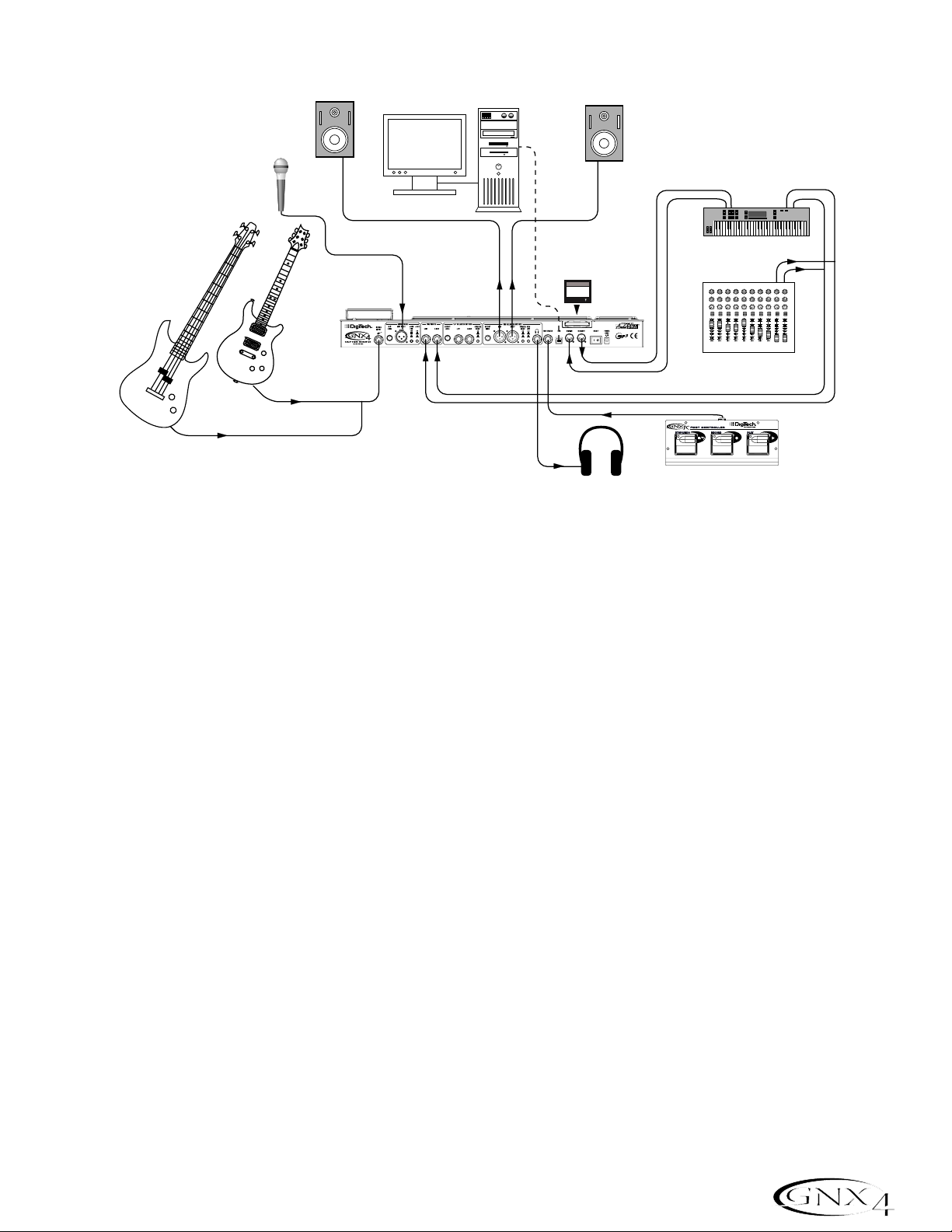
Computer Recording Application
At the heart of your recording studio, the GNX4 serves both as your guitar processor and audio/MIDI
interface. With microphone input, line inputs, and MIDI I/O, you have a full featured interface for
recording almost any source you can think of. Connect your guitar or bass to the GNX4’s
Guitar/Instrument input and use the amp models for tracking your guitar and bass parts. Next, plug in
the mic and get your vocal or acoustic performance nailed. You can even add line level instruments or
feeds from submixes in and record these and all of this completely hands-free. Even your MIDI keyboard
performance can be recorded so you can try the par t with different synth voices later.
Since the GNX4 has professional balanced outputs,you can plug directly into your favorite powered
monitors and get the bonus of latency free recording to boot.
1.Connect your guitar (or bass guitar) to the GNX4’s Guitar Input.
2.Connect a microphone to the GNX4’s Mic Input and use the Mic Level control knob located next to
the Mic Input on the GNX4’s rear panel to adjust the microphone output level. To adjust your
microphone input level for optimal use see Optimizing the Mic Input Level on page 13.
3.Connect a pair of stereo headphones to the Headphone Output.
4.Connect a keyboard,line level instrument,or stereo mixer (for feeding submixes) to the GNX4’s Left
and Right Line Inputs. To adjust your line input levels for optimal use see Optimizing the Line Input
Levels on page 13.
5.Connect a GNXFC Foot Controller (optional) to the GNX4’s Footswitch jack.
6.Connect a MIDI keyboard to the GNX4’s MIDI In and Out/Thru jacks using 5 Pin MIDI cables.
7.Connect XLR cables from the GNX4’s Left and Right XLR outputs to powered studio monitors.
8.Connect the GNX4 to your computer’s USB jack using the included USB cable.
ATTENTION: Before using the GNX4’s USB connection,it is necessary to first install the
USB drivers provided on the X-Edit
™
Software CD. Consult the Software Installation Guide
that came with your GNX4 for the proper instructions on how to install the drivers for your
operating system.
9.Press the GNX4’s OUTPUT SETUP button and select “
STEROALL” as the output mode using the
DAT A WHEEL.
19
Making Connections
Computer
Powered Studio Monitor
USB Cable
Powered Studio Monitor
Microphone
MIDI
Audio
MIDI Keyboard
Guitar
Mic Input
Guitar
Input
XLR
Balanced
Outputs
Line Inputs
CF Card
CompactFlash
256 MB
®
2468
2468
0
10
Aux 1
46
2
2
8
0
10
Aux 2
-10+1
-2
+2
-2
-3
+3
-3
-4
+4
-4
-5
+5
-5
Pan
Mute
Mute
L / R
L / R
+10
+10
+5
+5
0
0
-5
-5
-10
-10
-20
-20
-30
-30
-∞
-∞
1234
0
Aux 1
46
0
Aux 2
-10+1
2468
2468
2468
2468
2468
2468
0
0
10
10
Aux 1
46
2
2
8
8
0
0
10
10
Aux 2
-10+1
+2
-2
+2
-2
+3
-3
+3
-3
+4
-4
+4
-4
+5
-5
+5
-5
Pan
Pan
Mute
Mute
L / R
L / R
+10
+10
+5
+5
0
0
-5
-5
-10
-10
-20
-20
-30
-30
-∞
-∞
2468
2468
0
10
0
10
0
10
0
10
10
0
10
0
10
Aux 1
Aux 1
Aux 1
Aux 1
Aux 1
46
Aux 2
-10+1
Pan
Aux 1
Aux 1
46
46
46
46
46
46
2
2
2
2
8
8
8
8
8
2
2
8
8
0
10
0
10
0
10
0
10
10
0
10
0
10
Aux 2
Aux 2
Aux 2
Aux 2
Aux 2
Aux 2
-10+1
-10+1
-10+1
-10+1
-10+1
-10+1
+2
-2
+2
-2
+2
-2
+2
-2
+2
-2
+2
-2
+3
+4
+5
+10
+2
-3
+3
-3
+3
-3
+3
-3
+3
-3
+3
-3
+3
-4
+4
-4
+4
-4
+4
-4
+4
-4
+4
-4
+4
-5
+5
-5
+5
-5
+5
-5
+5
-5
+5
-5
+5
Pan
Pan
Pan
Pan
Pan
Pan
Mute
Mute
Mute
Mute
Mute
Mute
L / R
L / R
L / R
L / R
L / R
L / R
+10
+10
+10
+10
+10
+5
+5
+5
+5
+5
+5
0
0
0
0
0
0
-5
-5
-5
-5
-5
-5
-10
-10
-10
-10
-10
-10
-20
-20
-20
-20
-20
-20
-30
-30
-30
-30
-30
-30
-∞
-∞
-∞
-∞
-∞
-∞
R
5
6
7
8
L
Stereo Mixer
Bass Guitar
Headphones
GNXFC Foot Controller
(Optional)
Page 30
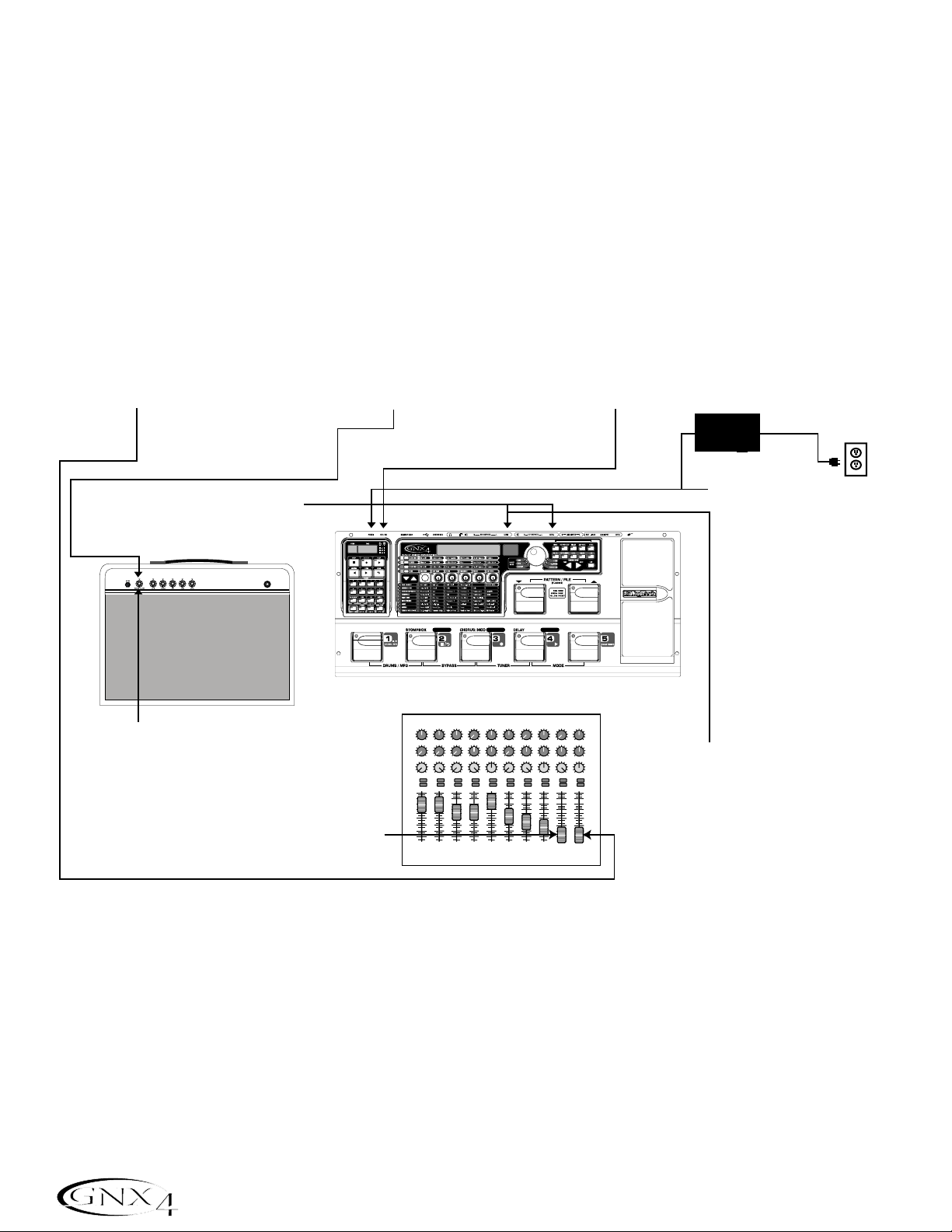
Applying Power
Before applying power to anything,set your amp(s) to a clean tone and set the tone controls to a flat EQ
response (on most amps,this would be 0 or 5 on the tone controls). Then do the following:
1. Turn your amp volume all the way down.
2.Pull the mixer’s master faders all the way down.
3. Turn the GNX4’s Output Level knobs all the way down (fully counter-clockwise).
4.Connect the plug of the PSS3 power supply to the GNX4’s Power Jack. Connect the other end of the
PSS3 power supply to an AC outlet.
5. Turn the GNX4’s power on.
6. Turn your amplifier(s) on and adjust the volume(s)to a normal playing level.
7.Push the mixer’s master faders up to the desired listening level.
8.Gradually increase the GNX4’s Output Levels to the desired listening level.
20
Making Connections
7. Push the Master Faders
up to the desired
listening level.
8. Turn the GNX4's Output
Level knobs up to the
desired listening level.
1. T urn your Amp V olume down.
2. Pull Master Faders
down completely.
6. Turn your Amp on and
adjust the Volume to
a normal playing
level.
CONTROL A CONTROL B CONTROL C
2468
2468
2468
2468
2468
2468
0
10
0
10
Aux 1
Aux 1
46
46
2
2
8
8
0
10
0
10
Aux 2
Aux 2
-10+1
-10+1
-2
+2
-2
+2
-3
+3
-3
+3
-4
+4
-4
+4
-5
+5
-5
+5
Pan
Pan
Mute
Mute
L / R
L / R
+10
+10
+5
+5
0
0
-5
-5
-10
-10
-20
-20
-30
-30
-∞
-∞
1234
0
Aux 1
46
2
0
Aux 2
-10+1
-2
-3
-4
-5
Mute
L / R
+10
+5
0
-5
-10
-20
-30
-∞
0
0
10
0
10
10
Aux 1
Aux 1
46
46
46
2
2
2
8
8
8
0
0
10
0
10
10
Aux 2
Aux 2
-10+1
-10+1
-10+1
+2
-2
+2
-2
+2
-2
+3
-3
+3
-3
+3
-3
+4
-4
+4
-4
+4
-4
+5
-5
+5
-5
+5
-5
Pan
Pan
Pan
Mute
Mute
Mute
L / R
L / R
L / R
+10
+10
+10
+5
+5
+5
0
0
0
-5
-5
-5
-10
-10
-10
-20
-20
-20
-30
-30
-30
-∞
-∞
-∞
5
5. Turn the GNX4 on.
PSS3
Power Supply
4. Connect the PSS3 to the
GNX4's Power Jack and
connect the other end of
the PSS3 to an AC outlet.
TAP T EMPOAMP CHANNEL
2468
2468
0
10
Aux 1
Aux 1
46
2
8
0
10
Aux 2
Aux 2
-10+1
+2
-2
+3
-3
+4
-4
+5
-5
Pan
Mute
L / R
+10
+5
0
-5
-10
-20
-30
-∞
6
2468
2468
0
10
10
0
10
0
10
Aux 1
Aux 1
Aux 1
46
46
46
2
8
8
2
2
8
8
0
10
10
0
10
0
10
Aux 2
Aux 2
Aux 2
-10+1
-10+1
-10+1
+2
-2
+2
-2
+2
-2
+3
-3
+4
-4
+5
Pan
Mute
L / R
+10
+5
0
-5
-10
-20
-30
-∞
7
+2
+3
-3
+3
-3
+3
+4
-4
+4
-4
+4
-5
+5
-5
+5
-5
+5
Pan
Pan
Pan
Mute
Mute
L / R
L / R
+10
+10
+5
+5
0
0
-5
-5
-10
-10
-20
-20
-30
-30
-∞
-∞
R
8
L
3. Turn the GNX4's Ouput
Level knobs down.
Page 31
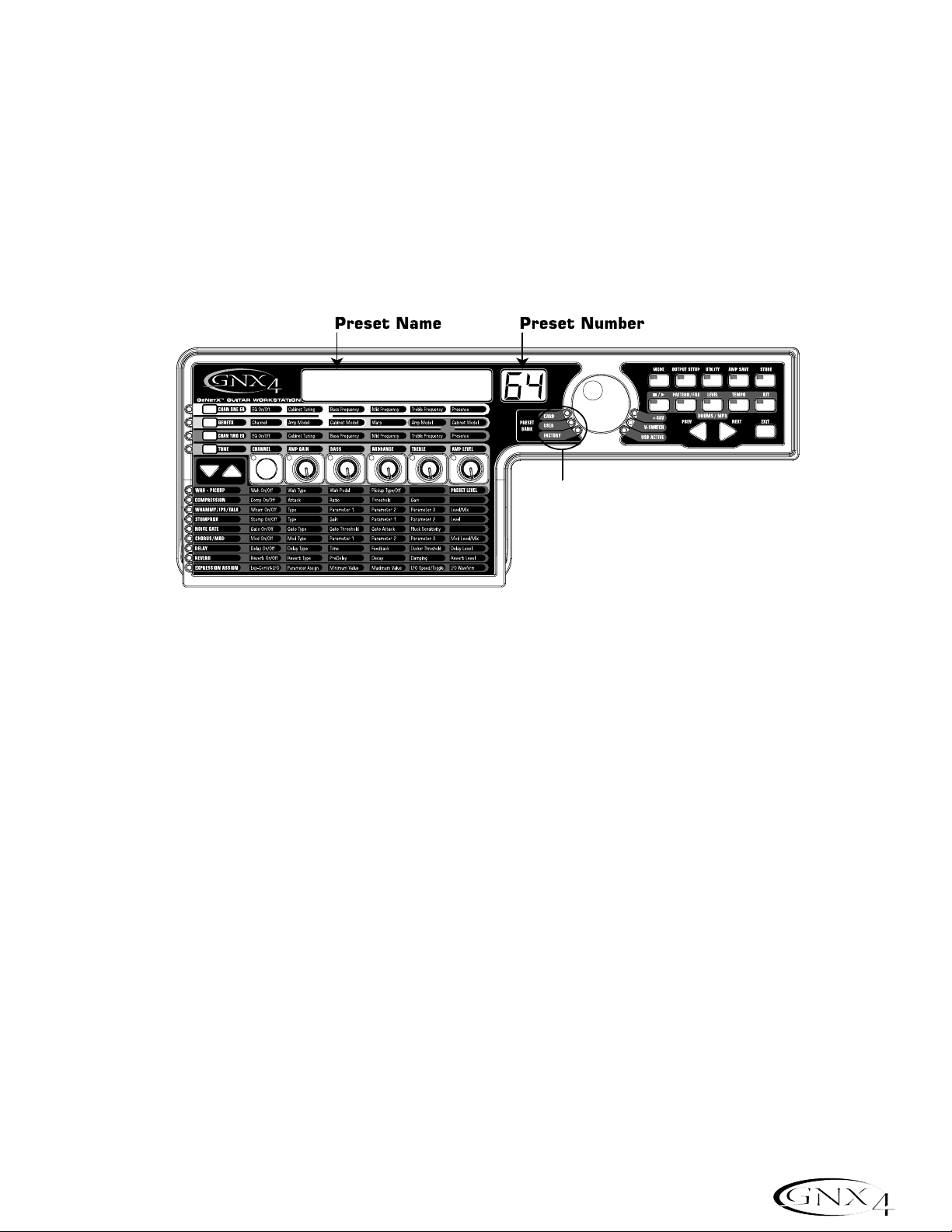
Presets
A preset is a named and numbered location of a programmed sound that resides in the GNX4. Presets can
be recalled with the Footswitches or the DA TA WHEEL. The GNX4 comes with 80 Factor y and 80 User
presets. The Factory Presets do not let you store changes to them. The User presets let you store changes.
From the factory, the 80 User presets are exact duplicates of the 80 Factory presets. This lets you create
your own presets without worrying about losing any of the original presets. When you select a preset,the
name of the preset appears in the green display and the number of the preset appears in the red numeric
display. The User LED to the left of the DAT A WHEEL lights indicating the User preset is active. The
Factory LED lights indicating a Factor y preset is active and the Card LED lights indicating a preset from a
Compact Flash
®
Memory Card inserted into the GNX4’s Memory Card slot is active.
Footswitch Modes
When you first apply power to the GNX4, it powers up in one of three Footswitch Modes:Preset,
Stompbox/Control,or Recorder. The Footswitch Modes are selected in two different ways:
Press the MODE button (located to the right of the D A T A WHEEL)
Or
Press and hold Footswitches 4 and 5 simultaneously.
Depending on which mode is selected,the UP/DOWN footswitch LEDs will light a different color. When
Preset Mode is selected,the UP/DOWN footswitches will be lit green. When Stompbox/Control
Mode is selected, the UP/DOWN footswitches will be lit yellow. And when Recorder Mode is selected,
the UP/DOWN footswitches will be lit red. In any of the modes,the display shows the selected preset’s
name and number. The vertical LEDs on the Matrix indicate which effects are active for the selected preset.
Preset Mode
The GNX4’s Presets are grouped into sixteen banks of five presets. (See the Preset List on page 112
for a complete list of Presets with their respective Bank locations.) When Preset Mode is active the
UP/DOWN footswitches are used to select one of the sixteen Factory,User,or Card Banks. Successive
presses of the UP/DOWN footswitches advances through all Factory/User/Card Banks. Pressing and
holding the UP/DOWN footswitches scrolls through the Factory/User/Card Banks. Once a Bank is
selected,Footswitches 1-5 will flash indicating a preset within that bank needs to be selected. If a
preset is not selected within 5 seconds,the GNX4 returns to the currently selected bank and preset. A
second press of the same footswitch bypasses the preset. Another press reactivates the preset.
21
About the GNX4
Name
LEDs Indicate Whether a Card,
User, or Factory Preset is Active
Page 32

Preset Bounceback
If you would rather not bypass individual presets in Preset Mode by pressing their footswitches
repeatedly, you can enable the Preset Bounceback function in the Utility menu. For example, let’s say
you select Preset 1 using FOOTSWITCH 1 as your rhythm tone. Then you select Preset 4 using
FOOTSWITCH 4 as your solo tone. You can now press FOOTSWITCH 4 again and Preset 1
will be selected again. Pressing FOOTSWITCH 4 repeatedly will bounceback between Preset 4 and
Preset 1. To enable the Preset Bounceback feature,do the following:
1. Press the UTILITY control panel button and use the PREV/NEXT arrow buttons to locate the
Bounceback feature. The display will read BOUNCBAK.
2. Rotate the DATA WHEEL to turn the BounceBack feature on.
3. When finished press the EXIT button.
NOTE: The Preset Bounceback feature only works when the GNX4 is in Preset Mode.
For more information regarding the footswitch functions for Preset Mode see page 59.
Stompbox/Control Mode
Stompbox/Control Mode is another mode of operation that can be used during a performance. When
Stompbox/Control Mode is active, the UP/DOWN footswitches are used to select the GNX4’s presets.
Footswitches 1-4 turn the effects on and off. Footswitch 5 is used as a Tap-Tempo switch for setting the
delay time during a live performance.
For more information regarding the footswitch functions for Stompbox/Control Mode see page 60.
Recorder Mode
When Recorder Mode is active, the GNX4’s UP/DOWN footswitches are used for selecting songs
and loops that reside in the recorder’s memor y. The 1-5 footswitches are used for hands-free control of
the recorder’s functions.
For more information regarding the footswitch functions for Recorder Mode see page 61.
Expression Pedal
The Expression Pedal can control three different parameters simultaneously in each preset. Rock the
Expression Pedal back and forth to change the values of the assigned parameters. Each parameter the
Expression Pedal controls has an adjustable minimum and maximum range. The Expression Pedal also
includes a feature called V-Switch and when enabled, it turns on the wah effect and switches from controlling
the parameters assigned to the Expression Pedal and controls the Wah. See page 45 for more information on
Expression Pedal Pedal Assignment.
22
About the GNX4
Page 33

Bypass
The GNX4 presets can be bypassed for a clean,unprocessed guitar tone. Bypass turns off all effects and
modeling. To bypass the GNX4 in Preset Mode, press the active preset’s Footswitch (the 1-5 footswitch
that is lit),or press Footswitches S 2 and 3 simultaneously. To bypass the GNX4 while in
Stompbox/Control or Recorder Mode, press Footswitches 2 and 3 simultaneously. When the GNX4 is
bypassed,the display reads
BYPASS and all LEDs in the Matrix are off. Press any Footswitch to exit Bypass
and return to the last preset. The Matrix and Programming buttons do not function when Bypass is activated.
NOTE: If Preset Bounceback is enabled in the Utility menu,pressing the active preset’s
footswitch while in Bank Mode will not bypass the GNX4’s effects. To bypass the GNX4’s
presets while Preset Bounceback is enabled you must press Footswitches 2 and 3
simultaneously.
Tuner
The Tuner in the GNX4 lets you quickly tune or check the tuning on your guitar. Press Footswitches 3 and
4 simultaneously to access the Tuner. The display briefly flashes
TUNER. To begin tuning, play a note on your
guitar (a harmonic at the 12th fret usually works best).The red numeric display shows the note being played,
and the green alpha-numeric display indicates whether the note is sharp or flat. Arrows to the left (
<<<)
indicate the note is sharp and should be tuned down. Arrows to the right (
>>>) indicate the note is flat and
should be tuned up. When your note is in tune,
-><- is displayed.
While the tuner is selected,you can set your tuning reference with the D A T A WHEEL. The default factor y
setting is A=440 Hz. The tuning references range from 427 Hz to 453 Hz (± 50 cents (1/2 semitone) from
either direction of 440 Hz). Below 427 Hz, are alternate dropped tunings. The alternate tunings are
REF A(A=Ab),REF G(A=G), and REF G(A=Gb). The display window briefly flashes the selected tuning
preference.
23
About the GNX4
Page 34

The GNX4 Matrix
The main panel of the GNX4 is the Matrix. The Matrix is comprised of two main sections, Amp/Cabinet
and Effects. It is used to navigate through the GNX4’s amp/cabinet modeling and effects parameters. Upon
power up, the GNX4 defaults to the TONE amp control row in the Amp/Cabinet section and any effects
that are enabled within a preset will have their corresponding LEDs lit in the Effects section of the Matrix.
You can select one of the other three Amp Control rows,CHAN 1 EQ, GENETX, or CHAN 2 EQ using
the Amp Control Buttons or you can select the different effects and their parameters using the Effect
Select buttons. The LED to the left of each row indicates which row is active,while the Status Button
and five Knobs control the corresponding parameter above or below each knob.
Viewing/Editing GENETX™and Amp Parameter V alues
To view or edit an amp parameter’s current value,you must first select the row in which the parameter
resides using the Amp Control buttons located to the left of the amp parameter rows. After selecting
the desired row, use the Status Button and Knobs to adjust the parameters. When turning a knob one
click position the current value of the selected parameter will show in the display. If a Knob is turned
again within 3 seconds,the parameter value will be changed. If a Knob is not turned within 3 seconds,
the main display returns back to the preset name.
NOTE: If a parameter name is shown in the display while editing both Amps and Effects,the
DATA WHEEL can change the value as well as the Knobs.
24
GNX4 Matrix Functions
Amp Control
Buttons
AMP/CABINET
SECTION
Status Button
Effect Select
Buttons
EFFECTS
SECTION
Knobs
Amp Control
Buttons
AMP/CABINET
SECTION
Status Button
Knobs
Data Wheel
Page 35

Viewing/Editing Effect Parameter Values
To view or edit an effect parameter’s current value,you must first select the row in which the desired
parameter resides by using the Effect Select Buttons. They are located to the left of the Status
Button. After selecting the desired effect,use the Status Button and Knobs to adjust the effect’s
individual parameters. Parameter adjustments will show in the displays as edits are made. To exit effect
editing,press the EXIT button in the Control Panel.
NOTE: If a parameter name is shown in the display while editing both Amps and Effects,the
DATA WHEEL can change the value as well as the Knobs.
25
GNX4 Matrix Functions
Status Button
Effect Select
Buttons
EFFECTS
SECTION
Knobs
Page 36

GENETX Row
The GENETX row is where amp and cabinet models are selected for the current preset. It is also
where the Warp function resides allowing GeNetX™warping between the two amp models. When the
GENETX row is selected,the Knobs and Status Button perform the following functions:
STATUS BUTTON
Selects between Amp Channel 1 (Green) and Amp Channel 2 (Red) and lets you hear each channel
independently,or if a Warped state (Yellow) between both channels exists, this button selects it and
lets you hear the warped amp. The Status Button’s LED will light Green,Red, or Yellow depending on
which channel is selected.
KNOB 1
Selects the Channel 1 (Green) amp model and the LED for Knob 1 is lit green.
KNOB 2
Selects the Channel 1 (Green) cabinet model and the LED for Knob 2 is lit green.
KNOB 3
Warps the Channel 1 and Channel 2 amp and cabinet models together. Setting this knob to its
minimum position selects Channel 1’s amp and cabinet only and the LED for Knob 3 is lit green.
Setting this knob to its maximum position selects Channel 2’s amp and cabinet only and the LED for
Knob 3 is lit red. Setting Knob 3 to any other position selects a warped state, a combination of
Channel 1 and 2’s amp and cabinet models and the LED will be lit yellow.
KNOB 4
Selects the Channel 2 (Red) amp model and the LED for Knob 4 is lit red.
KNOB 5
Selects the Channel 2 (Red) cabinet model and the LED for Knob 2 is lit red.
26
GNX4 Matrix Functions
GENETX ROW
STATUS
BUTTON
KNOB
1
KNOB
2
KNOB
3
KNOB
4
KNOB
5
Page 37

CHAN ONE EQ and CHAN TWO EQ Rows
The CHAN ONE EQ and CHAN TWO EQ rows are used for modifying the center frequencies of
the Bass,Midrange , and Treble controls of that reside within the TONE Row. A Presence control is
available here for editing amp tone as well. There is also a Cabinet Tuning control for changing the tuning
of a selected channel’s cabinet resonance. When either the CHAN ONE EQ or CHAN TW O EQ
row is selected,the knobs and STATUS button perform the following functions:
STATUS BUTTON
Turns the EQ on and off for the selected channel.
KNOB 1
Adjusts the Cabinet Tuning resonance of the cabinet model for the selected channel. The Cabinet
Tuning ranges are from one octave below (-
1™0) to one octave above (1™0).
KNOB 2
Selects the Bass Center Frequency for the selected channel. The Bass Center Frequency range is
from 50Hz (
50) to 300Hz (300).
KNOB 3
Selects the Midrange Center Frequency for the selected channel. The Midrange Center Frequency
range is from 300Hz (
300 HZ) to 5000Hz (5000 HZ).
KNOB 4
Selects the Treble Center Frequency for the selected channel. The Treble Center Frequency range is
from 500Hz (
500 HZ) to 8000Hz (8000 HZ).
KNOB 5
Boosts or cuts the Presence Level for the selected channel. The Presence Control is a shelf EQ and
has a fixed frequency of 7500Hz. The Presence Level range is from -12dB (
-12) to 12dB (12).
27
GNX4 Matrix Functions
CHAN ONE EQ & CHAN TWO EQ ROWS
STATUS
BUTTON
KNOB
1
KNOB
2
KNOB
3
KNOB
4
KNOB
5
Page 38

Here is an example of how the CHAN ONE EQ row would function when the button is pressed:
Warped Amp Sound being heard:
If the sound being heard is a Warped sound of both amp models,pressing the CHAN ONE EQ button
selects the knobs to control the CHAN ONE EQ’s row of parameters. The STATUS button LED will
light yellow,indicating a Warped sound is being heard,and the knobs will all light green. You can modify
the CHAN ONE EQ row parameters which will be heard as the knobs are turned. The STATUS
button will turn the CHAN ONE EQ on or off and indicate this status by turning the button LED on
and off.
CHAN ONE amp sound being heard:
If the sound being heard is the CHAN ONE amp tone, pressing the CHAN ONE EQ button selects
the knobs to control CHAN ONE EQ’s row of parameters. The STATUS button and the knobs will
light green. You can modify the CHAN ONE EQ row parameters, which can be heard as the knobs are
turned. The STATUS button will turn the CHAN ONE EQ on or off and indicate this status by
turning the button LED on and off.
CHAN TWO amp sound being heard:
If the sound being heard is the CHAN TW O amp tone, pressing the CHAN ONE EQ button selects
the knobs to control the CHAN ONE EQ’s row of parameters. The STATUS button will be lit red
indicating you are still listening to the CHAN TW O amp tone . The knobs however will be lit green and
once any of them are turned,the sound will change from the CHAN TW O amp tone to the CHAN
ONE amp tone. You can then modify the CHAN ONE EQ parameters and these changes can be
heard as the knobs are turned. The STATUS button will also turn green at this time and can be used
to turn the CHAN ONE EQ on or off as will be indicated by the button’s LED turning on and off.
28
GNX4 Matrix Functions
Page 39

TONE Row
The TONE row is where the amp tone controls are located for Channel 1 or Channel 2. The sound
that you hear while adjusting these parameters will depend on the channel status (see chart below).
TONE control row parameters are Channel,Amp Gain, Bass,Midrange ,Treble,and Amp Level.
STATUS BUTTON
Selects one of the four channel states in the following order:
Ch1 amp -The status button LED lights green and the five control knobs light green indicating that
you are listening to Channel 1 and the control knobs affect Channel 1’s tone settings.
Ch1 warp -The status button LED lights yellow and the five control knobs light green indicating that
you are listening to a warped sound and the control knobs affect Channel 1’s tone
settings.
Ch2 amp -The status button LED lights red and the five control knobs light red indicating that you
you are listening to Channel 2 and the control knobs affect Channel 2’s tone settings.
Ch2 warp -The status button LED lights yellow and the five control knobs light red indicating that
you are listening to a warped sound and the control knobs affect Channel 2’s tone
settings.
KNOB 1
Controls the amount of Amp Gain.The Amp Gain range is from 0 to 99.
KNOB 2
Controls the Bass EQ Level (boost/cut). The Bass EQ Level range is from -12dB (-12) to 12dB (12).
KNOB 3
Controls the Midrange EQ Level (boost/cut). The Midrange EQ Level range is from -12dB (12) to
12dB (
12).
KNOB 4
Selects the Treble EQ Level (boots/cut). The Treble EQ Level range is from -12dB (-12) to 12dB (12).
KNOB 5
Controls the Amp Level. The Amp Level Range is from 0 to 99.
29
GNX4 Matrix Functions
TONE ROW
STATUS
BUTTON
KNOB
1
KNOB
2
KNOB
3
KNOB
4
KNOB
5
Page 40

Amp/Cabinet Modeling
The GNX4 was designed to make sound processing easy and intuitive. Because the GNX4 provides both
Amp Modeling and Effects Processing,the editing functions are divided into two sections:the Amp/Cabinet
Modeling section and the Effects section. The GeNetX
™
technology contained in the GNX4 lets you go much
further than mere Amp Modeling. GeNetX lets you create your own Amp/Cabinet HyperModel
™
and store
this custom creation to a User Amp/Cabinet location. When editing either the Amp/Cabinet Modeling,or the
Effects section,you must start with one of the User or Factory Presets. The preset you begin with does not
need to be in the location that you intend to save it.
After selecting a preset,you can select the Amp Models or Cabinet Types for your preset. Amp/Cabinet
Modeling applies the tone of one of several vintage or modern Amp Models and Cabinet Types to your guitar
signal. The GNX4 includes accurate emulations of 15 guitar Amp Models, 10 Bass Amp Models,one Acoustic
Guitar Simulation,and 22 Speaker Cabinet Types.Your choices include:
Amp Models
Marshall, Vox,Fender, Matchless,HiWatt, Ashdown,Ampeg, Trace-Elliot, Sunn, Hartke and Mesa Boogie, are trademarks of their respective
companies and are in no way associated with DigiTech
®
.
30
Amp/Cabinet Modeling
Direct
Guitar Amps
Acoustic
Bass Amps
User
direct 1 Turns the amp modeling off
blackfac 2 Based on a '65 Fender Twin Reverb
boutique 3 Based on a Matchless DC30
rectfied 4 Based on a Mesa Dual Rectifier
hot rod 5 Based on a Mesa Boogie Mark II C
Tweed 6 Based on a '57 Fender Tweed Deluxe
britcmbo 7 Based on a Vox AC30 top boost
cleantub 8 A clean tube combo setting
britstck 9 Based on a '78 Marshall Master Volume
crunch 10 A nice crunchy tube amp combo
hi gain 11 A high gain tube amp
blues 12 A sweet, tube, blues tone
mdrngain 13 Based on a Marshall JCM900
fuzz 14 A high gain fuzz distortion
bass man 15 Based on a Fender Bassman
hiwattag 16 Based on a HiWatt 50 watt stack
acoustic 17 A flat top acoustic guitar
rockbass 18 Based on an Ampeg SVT
mdrnbass 19 Based on an Ashdown ABM-C410H
britbass 20 Based on a Trace-Elliot Commando
solar 21 Based on a Sunn 200S
vintage 22 Based on a ‘69 Ampeg SVT Classic
bomber 23 Based on a Ampeg B15
basic 24 Based on a SWR Basic Black
Dualshow 25 Based on a Fender Dual Showman
boogiman 26 Based on a Mesa Boogie Bass 400+
hartkey 27 Based on a Hartke Model 2000
empty u1 to u9 User HyperModel Locations
Page 41

Cabinet T ypes
Fender, Ampeg,Ashdown, Sunn, Fane, Acoustic, Har tke, SWR, are trademarks of their respective companies and are in no way associated with
DigiTech
®
.
Editing Amp Models and Cabinet Types
Each GNX4 preset has three channels,Channel 1 (green),Channel 2 (red), and Warp (yellow). Amp channels
1 and 2 have selectable amps and cabinets. Each channel has independent controls for gain, level,EQ, and
cabinet tuning. The Warp channel is effectively a mixture of the Channel 1 and 2 amps and cabinets using the
Warp knob in the Amp Controls section of the matrix. When parameter values have changed,the Store LED
lights indicating the preset has been modified and needs to be stored (see page 58 for more on the storing
procedure).
Once you have selected your amps for Channel 1 and 2,you can switch between these,as well as the Warp
channel,using the Amp Channel footswitch (Stompbox/Control Mode only) or the Status button (GeNetX
row is active) when the preset name is displayed. The following sections guide you through the process of
selecting amps and cabinets,adjusting amp parameters, performing cabinet tuning, and creating then saving a
Hypermodel
™
Amp.
r
31
Amp/Cabinet Modeling
Direct
Guitar Cabinets
Bass Cabinets
User
direct 1 Turns the cabinet modeling off
amer2x12 2 Based on an American 2x12
brit4x12 3 Based on a British 4x12
vntg4x12 4 Based on a Vintage 30 4x12
brit2x12 5 Based on a British 2x12
twed1x12 6 Based on an American 1x12
blnd2x12 7 Based on a Blonde 2x12
fane4x12 8 Based on a Fane 4x12
grnb4x12 9 Based on a Greenback 4x12
botq4x12 10 Based on a Boutique 4x12
amer4x10 11 Based on a Bassman 4x10
65 1x12 12 Based on a '65 Tweed 1x12
jazz1x15 13 Based on a Fender Pro 1x15
bass1x15 14 Based on an Ampeg Portaflex
bass4x10 15 Based on an Ashdown 4x10 w/Tweete
bass2x15 16 Based on a Sunn 200S 2x15
fold1x18 17 Based on a Acoustic 360
hart1x15 18 Based on a Hartke 1x15
basic 15h 19 Based on a SWR Basic Black
vntg8x10 20 Based on an Ampeg 8x10
ash 4x10 21 Based on an Ashdown ABM 410
glth4x10 22 Based on an SWR Goliath III
hart4x10 23 Based on a Hartke 4x10
empty U1 to U9 User Locations
Page 42

Selecting Amp Models and Cabinet Types
The first step to editing an Amp,Cabinet Type, or creating your own HyperModel is to select the Amp
and Cabinet types for Channel 1 and Channel 2 in your preset. The procedure for selecting Amps or
Cabinets is as follows:
1.Press the GENETX Amp Control button.
2.Use Knob 1 to select the Amp for Channel 1. The Amp name appears in the display. (See page 30
for a complete list of Amp Models.)
4.Use Knob 2 to select the Cabinet for Channel 1. The Cabinet name appears in the display. See
page 31 for a complete list of Cabinet T ypes.)
5.Use Knob 4 to select the Amp for Channel 2. The Amp name appears in the display.
6.Use Knob 5 to select the Cabinet for Channel 2. The Cabinet name appears in the display.
Adjusting Amp Parameters
The Gain,EQ, and Level Parameters can be adjusted individually for the Channel 1 and Channel 2.
This is accomplished by pressing the TONE Amp Control button. The sound that you hear while
adjusting the knobs depends on the state of the Status Button and the Knobs (see char t below).
When the TONE row is selected,the Status Button steps through four states in the following order :
Ch1 amp -The status button LED lights green and the five control knobs light green indicating that
you are listening to Channel 1 and the control knobs affect Channel 1’s tone settings.
Ch1 warp -The status button LED lights yellow and the five control knobs light green indicating that
you are listening to a warped sound and the control knobs affect Channel 1’s tone
settings.
Ch2 amp -The status button LED lights red and the five control knobs light red indicating that you
you are listening to Channel 2 and the control knobs affect Channel 2’s tone settings.
Ch2 warp -The status button LED lights yellow and the five control knobs light red indicating that
you are listening to a warped sound and the control knobs affect Channel 2’s tone
settings.
The Gain ranges from 0 (
0) to 99 (99). The Bass, Midrange, and Treble EQ range from -12 db(-12) to
+12db (
12). The Level ranges from 0 (0) to 99 (99). The procedure for adjusting these parameters is as
follows:
1.Press the TONE Amp Control button.
2.Press the STATUS button to select either Channel 1 Amp (Green) or Channel 2 Amp (Red).
3.Use Knobs 1 through 5 to adjust the Gain, Tone,and Level of the selected amp channel.
Cabinet T uning
Cabinet tuning actually changes the resonant frequency of the selected cabinet. This is useful for changing
the tonality of your sound without having to touch the EQ parameters. Tuning down gives the sound
more bottom end while tuning up enhances higher frequencies. The procedure for tuning the cabinets is
as follows:
1.Press the CHAN ONE EQ or the CHAN TWO EQ Amp Control button to access the Cabinet
Tuning parameters.
2.Use Knob 1 to adjust the Cabinet Tuning resonance. The Cabinet Tuning ranges are from
-1™0
(one octave below) to 1™0 (one octave above) the cabinet’s standard resonance.
32
Amp/Cabinet Modeling
Page 43

Storing Amp Parameter Edits
Once you are satisfied with your amp edits, these changes need to be stored so that they can be recalled
later. See page 58 for more information on storing changes to a preset.
Creating HyperModels
™
Creating new,unique HyperModels is what GeNetX™is all about. Once both channels Amps and Cabinets
are selected and the Amp Parameters and Cabinet Tunings have been adjusted,GeNetX technology lets you
do something amazing. The characteristics of each Amp and Cabinet can be combined or “Warped” to create
a completely new HyperModel Amp. The procedure for Warping the Channel 1 and Channel 2 Amps
together is as follows:
1.Press the GENETX amp control button.
2.Rotate Knob 3 to Warp the Channel 1 and Channel 2 Amps and Cabinets together. Rotating it
counter-clockwise emphasizes the Channel 1 characteristics while rotating it clockwise emphasizes the
Channel 2 characteristics. A warp value of 1 produces the amp tone of only the Channel 1 (Green)
Amp. A warp value of 99 produces the amp tone of only the Channel 2 (Red) Amp.
Saving HyperModels (Amp Save)
When you have found your ideal warp setting for Channel 1’s and Channel 2’s Amp Models, you can save this
sound as a HyperModel for future use. This HyperModel can be saved in one of 9 User locations. After it
has been saved, it can now be selected by either Amp Channel as the starting point for a new Hypermodel.
The Amp Save procedure is as follows:
1.Press the AMP SAVE button. The AMP SAVE button will begin flashing and the display will read
NEWAMP. The N of NEWAMP is flashing indicating that you can name your HyperModel.
2.Use the DA TA WHEEL to select the alpha-numeric character.
3.Use the NEXT button to move to the next character (to the right), or the PREV button to select
the previous character (to the left).
4.Repeat steps 2 and 3 you have finished naming the new HyperModel.
5.Press the AMP SAVE button again to select one of the 9 User HyperModel locations. If the GNX4
has any unused HyperModel locations available, the display will read
U1. The U1 flashes indicating that
this is the first available location for HyperModel to be stored. If all 9 HyperModel locations are full,
the GNX4 defaults to the first HyperModel location and displays the name of HyperModel stored in
the first location.
6.Use the DA TA WHEEL to select a User location to save the HyperModel. If all locations have been
used,the display shows the name of the HyperModel about to be overwritten.
7.Press the AMP SAVE button again to complete the Amp Save procedure.
Press the EXIT button at any time during the Amp Save procedure to abort the process.
NOTE: The Amp Save procedure only saves Amp/Cabinet combinations to the User
HyperModel locations. It does not store changes or the new HyperModel to the
selected preset. See page 58 for information on storing changes to a preset.
33
Amp/Cabinet Modeling
Page 44

Effects and Parameters
The GNX4 features a comprehensive set of effects for creating just the sound you need for any musical
application. These effects are connected in a standard effects chain with pickup simulator, wah, compressor,
Whammy™/IPS,and distortion stompbox effects placed before the amps. Effects placed post amp are those
that typically sound best when heard in stereo like modulation effects,delay and reverb. The following
diagram show the signal path through the effects of the GNX4:
Editing a Preset’s Effects
The Effects section is accessed with the Effect Select Up/Down buttons.The Matrix LEDs light one at a
time to identify the selected row of effects . Each effect has up to 5 Parameters that can be edited. Pressing
the Status Button turns the effect row on and off. The 5 knobs control the Parameters listed directly
beneath the corresponding knob. Each effect’s parameter is labeled in the Matrix. When a knob is turned,
the corresponding parameter name and value appear in the displays.
Rotating the Knobs increases or decreases the value of the parameter (except for Type which selects
different effect types) and you hear the change in real time. Changing presets,or turning the power off
before storing any changes will erase your changes and revert to the stored values. When the preset has
been edited,the Store LED turns on indicating that a change has been made . You may store your settings to
any of the 80 User Preset locations or on to an optional compact flash card.
34
Effects and Parameters
PRESET
LEVEL
SPEAKER
COMPENSATION
GNX4
OUTPUTS
Edit
Page 45

Effect Definitions
Each Effect within the GNX4 is fully programmable. Understanding how these effects modify the sound,and
how each parameter alters the effect will help you achieve the sound you are looking for. The following
overview outlines how each effect and parameter in the GNX4 works.
Preset Levels
The GNX4 presets each have an independent level control for quick balancing of the levels between presets.
Preset Level is accessed by selecting the Wah – Pickup row of the Matrix using the Effect Select buttons
and then adjusting Knob 5. The Preset Level adjusts the overall output gain of the active Preset and the
range is from
0 to 99. Preset Level changes need to be saved and stored to a user preset location just as any
other effect changes. See page 58 for more information on Storing a Preset.
Wah-Pickup
A Wah is an effect controlled by the Expression Pedal. A Wah applies a boost in gain to a narrow band
of frequencies. As the Expression Pedal is rocked back and forth, the center frequency receiving the
boost is swept up and down making the guitar sound as if it is saying “Wah”. The Wah is engaged and
disengaged by applying pressure to the V-Switch located under the toe of the Expression Pedal. See page
104 for more information regarding the V-Switch.
The Pickup Simulator applies the warmth and thickness of a double coil humbucker pickup to a single coil
guitar,or the unique, crisp sound of a single coil pickup to a guitar with a humbucker. This allows you to
have the best of both worlds without ever changing guitars.
Wah On/Off - The Status button (or the V-Switch) turns the Wah (
Wah) on and off.
Wah T ype - Knob 1 selects the type of Wah.Values include:Cr y Wah (
CRY) is a traditional sounding
W ah, Boutique W ah (
BOuTIQUe) is a wide sweeping Wah with a more modern sound and
Full Range Wah (
fullrang) sweeps the entire spectrum of audible frequencies.
Wah Pedal - Knob 2 controls the pedal (
wah pdl) parameter that adjusts the wah sweep when the
wah is active. The wah sweep range is from
0-99. The Expression Pedal is automatically
linked to this parameter when the V-Switch is engaged. To adjust the minimum and
maximum range, see the Expression Pedal section on page 45.
Pickup T ype/Off - Knob 3 selects the type of Pick Up to be be simulated. Values include: Pickup
Simulator Off (
pick off), Single Coil>Humbucker (SC>humb) gives a single coil pick
up the warm tone of a humbucker, and Humbucker>Single Coil (
humb>SC) gives a
humbucker the unique sound of a single coil.
Knob 4 has no function when the Wah-Pickup is selected.
Preset Level - Knob 5 adjusts the overall preset level. Ranges from
0-99.
Compressor
A compressor is used to increase sustain,and even out the volume dynamics in guitar signal. A
compressor sets boundaries for a signal’s strength. When a signal exceeds the set boundar y,it is forced
back into the set boundary. As the signal fades to a point where it no longer exceeds the boundary, the
compressor expands the signal strength and increases sustain. The compression parameters are as
follows:
Comp On/Off -The Status button turns the Compressor (
Compress) on and off.
Attack - Knob 1 adjusts the length of time it takes for the Compressor to respond to a signal
exceeding the Threshold. Values include:
fast, meDIUM,and slOw.
Ratio - Knob 2 adjusts the input to output ratio once the Threshold has been exceeded.For instance, a
Ratio of 4 to 1 means that a signal exceeding the Threshold by 4 dB will only be allowed 1 dB of
increased output.Higher settings yield a tighter,sound and increase sustain. Lower settings allow
35
Effects and Parameters
Page 46

better dynamics. Ratio settings are: 1.2:1 (¡2-1), 1.5:1 (¡5-1), 1.8:1 (¡8-1), 2:1 (™0-1), 2.5:1
(
™5-1),3:1 (£0-1), 4:1 (¢0-1), 5:1 (∞0-1), 8:1 (•0-1), 10:1 (10-1), 20:1 (20-1), and Infinity:1
(
INFnty-1).
Threshold - Knob 3 selects the Threshold (
threshld). The Threshold is the level a signal is allowed to
reach before the compressor begins to work. Low Threshold settings activate the
compressor with weaker signals. Higher settings require a stronger signal to activate
compression. Ranges from
0 to 99.
Gain - Knob 4 adjusts the Output Gain (
CMP Gain) from the Compressor. This parameter is used to
balance the level of the Compressor to reach unity gain. Other effects can clip if the Compressor
Gain too high. Ranges from
0 to 20(dB).
Knob 5 has no function when the Compressor is selected.
Whammy™/IPS/Talk
This module includes four types of pitch altering effects: Whammy,IPS, Detune, Pitch Shift, and the Talker
™
effect. Only one of the effects in this row can be used at a time. After selecting the type of effect in this
module, the Knobs 2-5 can then be used to adjust the individual parameters associated with the selected
effect. The following pages describe each effect and their parameters in more detail.
Whammy/IPS/Talk On/Off -When the Whammy/IPS/Talk effects module is selected the Status
button turns the Whammy/IPS/Talk effects on and off.
Whammy/IPS/Talk Select - Knob 1 selects whether the module is a Whammy (WHAMMY), Intelligent
Pitch Shifting (IPS),Detuner (DETUNE), Pitch Shift (PITCH), or T alker
(Talker 1-5).
Whammy
Whammy is an effect that uses an Expression Pedal to bend the pitch of the incoming signal,or add a
bendable harmony with the original signal. As the Pedal is moved,the note bends either up or down.
When Whammy is selected,it is automatically placed before the Amp Modeling as shown in the block
diagram (see page 34). The Whammy effect must be linked to the Expression Pedal in order to
function. See page 45 for more information on linking the Expression Pedal.
Parameter 1 - Knob 2 selects the interval and direction of the pitch bend. Choices are as follows:
Parameter 2 - Knob 3 provides a manual control of the Whammy Pedal (
wham pdl) position.
Ranges from
0 to 99.
Knob 4 has no function when the Whammy is selected.
Level - Knob 5 adjusts the Whammy Mix (
Wham mix) of all of the pitch-altering effects in this
module. Ranges from
0 to 99.
Whammy (no Dry Signal)
1 OCT UP (1 octave up)
2 OCT UP (2 octaves up)
2NDDOWN (a second down)
REV2NDDN (a second down reversed pedal
action)
4TH DOWN (a fourth down)
1 OCT DN (an octave down)
2 OCT DN (2 octaves down)
DIVEBOMB (Dive Bomb)
Harmony Bends (Dry Signal Added)
M3->MAJ3 (a minor third to a Major third)
2ND->MAJ3 (a second above to a Major third
up)
3RD->4TH (a third above to a fourth up)
4TH
->5TH (a fourth above to a fifth up)
5TH->OCT (a fifth above to an octave up)
H OCT UP (one octave up)
H OCT DN (one octave down)
octup->Dn (one octave up to one octave
down)
36
Effects and Parameters
Page 47

Intelligent Pitch Shifting (IPS)
Intelligent Pitch Shifting makes a copy of the incoming signal, and then changes the pitch of the copied
note to a diatonically correct interval specified by the Amount parameter. An Intelligent Pitch Shifter
sharpens or flattens the shifted pitch in order to keep the specified interval within the selected key
and scale creating a true harmony.
Parameter 1 - Knob 2 selects the Amount or harmony interval for the Intelligent Pitch Shifter.
Interval choices include:
Parameter 2 - Knob 3 selects the scale the IPS will use. Scale choices include:Major (MAJOR),
Minor (
MINOR),Dorian (DORIAN), Mixolydian (MIXoLYDn), Lydian (LYDIAN),
Harmonic Minor (
HARMINor).
Parameter 3 - Knob 4 selects the musical key the IPS uses. Key choices range from the Key of E
(
KEY E) through the Key of Eb (KEY Eb).
Level - Knob 5 adjusts the IPS Level (
IPS LEVL) of all the pitch-altering effects in this module .
Ranges from
0 to 99.
Detune
A Detuner makes a copy of your incoming signal,takes the copied signal slightly out of tune from the
original,and mixes the two signals together. The result is a doubling type of effect as if two guitars
were playing the same part together.
Parameter 1 - Knob 2 selects the Amount (
AMouNT) of detuning applied to the copied pitch in
cents (100 cents equals 1 semitone). Ranges are from 24 cents below (-24) to 24
cents above (24).
Knob 3 and Knob 4 have no function when Detune is selected.
Level - Knob 5 adjusts the Detune Level (
dtn LeVL) of all pitch-altering effects in this module .
Ranges from 0 to 99.
Pitch Shift
A Pitch Shifter copies the incoming signal,then shifts the pitch of the copied note to a different note.
The shifted note is then mixed back with the original signal sounding as if two guitars were playing
parallel notes.
Parameter 1 - Knob 2 selects the Shift (
SHIFT) of the pitch in semitone intervals. Ranges from
two octaves below (
-24) to two octaves above (24).
Knob 3 and Knob 4 have no function when Pitch Shift is selected.
Level - Knob 5 adjusts the Pitch Level (
pch LeVL) of all pitch-altering effects in this module .
Ranges from
0 to 99.
Talker
™
The Talker is an effect that lets your instrument’s signal be manipulated by your voice. The Talker
requires a microphone be connected to the Mic Input on the rear panel of the GNX4. As you speak
into the microphone,your instrument mimics what you say. There are five Talker types.
OCT DowN (octave down)
7TH DowN (a seventh below)
6tH DowN (a sixth below)
5tH DowN (a fifth below)
4tH DowN (a fourth below)
3RD DowN (a third below)
2ND DowN (a second below)
2ND UP (a second above)
3RD UP (a third above)
4TH UP (a fourth above)
5TH UP (a fifth above)
6TH UP (a sixth above)
7TH UP (a seventh above)
OCT UP (an octave above)
37
Effects and Parameters
Page 48

Type - Knob 1 is used to select one of the 5 Talker types. Talker types range from talker 1 (deep
tonal characteristics),to
talker 5 (bright tonal characteristics).
Sensitivity - Knob 2 adjusts the sensitivity of the microphone level (
MIC LEVL). The input level
from your microphone must be loud enough for the Talker to work properly. If the microphone input
is too weak,the Talker will have trouble tracking. If the input is too strong, the Talker will clip making
the words unintelligible. Adjust the mic level on the GNX4’s rear panel so that the LEDs light,but
stay below the the clip level. (See Optimizing the Mic Input Level on page 13 for more
information regarding mic level adjustment.) The mic level sensitivity ranges are from
0 (least
sensitive) to
99 (most sensitive).
Knob 3,Knob 4, and Knob 5 have no function when Talker is selected.
Stomp Box Modeling
The GNX4 Stomp Box Modeling emulates the tones of the most popular distortion boxes ever used
including the DOD OD250,Boss DS-1,Arbiter Fuzz Face , Electro Harmonix Big Muff,ProCo RAT, DOD
Grunge, Boss Metal Zone, Ibanez TS-9,Voodoo Labs Sparkle Drive,and the Guyatone OD-2*.
*Arbiter, Boss,Electro-Harmonix, ProCo,Ibanez,Voodoo Labs,Guyatone, DS-1, Fuzz Face, Big Muff, RAT, Metal Zone,TS-9,Sparkle Drive, and
OD-2 are trademarks of their respective companies and are in no way associated with DigiTech
Stomp Box On/Off - The Status button turns the Stomp Box Modeling on and off.
Type - Knob 1 selects the type of Stomp Box to be used. Choices include:
Screamer Based on an Ibanez TS-9 Guy OD Based on a GuyaTone OD-2
RODENT Based on a ProCo Rat Distortion SpArkDrv Based on a Voodoo Labs SparkleDrive
DS Dist Based on a Boss DS-1 Grunge Based on a DigiTech
®
Grunge
®
DOD 250 Based on a DOD Overdrive 250 Fuzzy Based on an Arbiter Fuzz Face
BIG MP Based on the Electro Harmonix Zone Based on a Boss Metal Zone
Big Muff Pi
Type Gain Param1 Param2 Param3* Param4* Level
Screamer drive tone level
Rodent dist filter volume
DS Dist dist tone level
DOD 250 gain level
Big MP sustain tone volume
Guy OD drive level
Sparkdrv gain tone clean volume
Grunge grnggain butt face loud
Fuzzy fuzz volume
Zone dist mid freq mid lvl low high level
Gain - Knob 2 controls the amount of Gain or distortion in the Stomp Box model. Range is from 0 to
99.
Parameter 1 - Knob 3 acts as a Tone control for each Stomp Box and controls the Mid Frequency of
the Zone model. Range is from
0 to 99.
Parameter 2 - Knob 4 acts as a second Tone control for the SparkleDrive, and Grunge Stomp Box
models and controls the Mid Level of the Zone model. Range is from
0 to 99.
*Parameter 3 - Controls the Low Frequency of the Zone model. Range is from
0 to 99.
*Parameter 4 - Controls the High Level of the Zone model. Range is from
0 to 99.
Level - Knob 5 controls the output level of the Stompbox model. Range is from
0 to 99.
*These Parameters are only available using the X-E
DIT
™
Editor/Librarian software.
38
Effects and Parameters
Page 49

Noise Gate
A Noise Gate is designed to eliminate hiss and ambient noise while you are not playing. A Noise Gate
can also be used to create an automatic swell in volume. The GNX4 includes two different types of
Noise Gates:Silencer
™
and Pluck. The Silencer™operates as a standard Noise Gate.The Pluck feature is
designed to close after every note (depending on the Pluck Sensitivity). This allows automatic volume
swells to occur on a note by note basis.
Gate On/Off - The Status button turns the Noise Gate (
gate) on and off.
Gate T ype - Knob 1 selects between the Silencer
™
(Silencer) or Pluck (PLUCK) type of Noise Gates.
Gate Threshold - Knob 2 sets the signal strength required to open or close the Noise Gate. The
Gate Threshold (
THRESHld) parameter ranges from 0 (opens easily) to 99 (requires
strong signals to open).
Gate Attack - Knob 3 adjusts the length of time it takes the gate to open (
ATTACK) and the signal to
become audible once the Threshold has been exceeded. Ranges from
0 (immediate
signal),to 9 (This setting will gradually ramp up the volume).
Pluck Sensitivity - Knob 4 selects the threshold (
PLUCKSNS) where the Gate re-triggers when using
the Pluck type Noise Gate. This parameter is only available when Pluck is the
selected type of Noise Gate. Ranges from
0 (requires strong signals) to 99 (re-
triggers with weak signals).
Knob 5 has no function when the Noise Gate is selected.
Chorus/Mod Effects
The Modulation Effects group is a multi-function module allowing you to select effects such as:Chorus,
Flanger,Phaser,Triggered Flanger, Triggered Phaser,Tremolo, Panner,Vibrato,Rotary Speaker,AutoYa™,
YaYa
™
,SynthTalk™,Envelope Filter (auto wah), Detune , and Pitch Shift. Only one of the effects in this row
can be used at a time. After selecting the type of effect in this module, the Knobs 2-5 can then be used
to adjust the individual parameters associated with the selected effect. The following pages describe each
effect and their parameters in more detail.
Chorus/Mod Effects On/Off -When the Chorus/Mod group is selected,the Status button turns the
Chorus/Mod Effects module on and off.
Chorus/Mod Effects Select - Knob 1 selects whether the module is a Chorus (Chorus), Flanger
(Flanger),Phaser (Phaser),Triggered Flanger (trigflng),Triggered
Phaser (trigphas), Tremolo (TREMOLO),Panner (PANNER),Vibrato
(VIBRATO),Rotar y (ROTARY),AutoYa (AUTOYA), YaYa (YAYA),
SynthTalk (SYNTHTLK), Envelope Filter (ENVELOPE),Detune
(DETUNE),Pitch Shift (PITCH).
Chorus
A Chorus adds a short delay to your signal.The delayed signal is modulated in and out of tune and
then mixed back with the original signal to create a thicker sound.
Parameter 1 - Knob 2 adjusts the rate (
Speed) of the modulation. Ranges from 0 to 99.
Parameter 2 - Knob 3 adjusts the intensity (
Depth) of the modulation. Ranges from 0 to 99.
Parameter 3 - Knob 4 adjusts the PreDelay (
PREDeLaY) or length of time before the Chorus effect
is applied to the input signal. Ranges from
1 to 20.
*Parameter 4 - Selects the waveform used by the Chorus. Waveforms include: Triangle, Sine, and
Square. Ranges from
1 to 20.
*Parameter 5 - Adjusts the left to right balance of the wet signal, Ranges from L
99 to R 99.
Mod Level - Knob 5 controls the level (mod levl) of the Chorus. Ranges from 0 to 99.
*These Parameters are only available using the X-E
DIT
™
Editor/Librarian software.
39
Effects and Parameters
Page 50

Flanger
A Flanger uses the same principle as a Chorus but has a shorter delay time and adds regeneration (or
repeats) to the modulating delay. This results in an exaggerated up and down sweeping motion to the
effect.
Parameter 1 - Knob 2 adjusts the rate (
Speed) of the modulation.Ranges from 0 to 99.
Parameter 2 - Knob 3 adjusts the intensity (
Depth) of the Modulation.Ranges from 0 to 99.
Parameter 3 - Knob 4 adjusts the amount of feedback (
Regen) added to the Flanger delay. Ranges
from 0 to 99.
Mod Mix - Knob 5 controls the mix (
mod mix) of wet and dr y signal. Ranges from 0 (all dry) to 99
(all wet).
Phaser
A Phaser splits the incoming signal,takes the split signal in and out of phase and mixes it back in with
the original signal. As the phasing changes,different frequencies are canceled resulting in a warm sort
of twisting sound.
Parameter 1 - Knob 2 adjusts the rate (
Speed) of the modulating phase. Ranges from 0 to 99.
Parameter 2 - Knob 3 adjusts the intensity (
Depth) of the modulation. Ranges from 0 to 99.
Parameter 3 - Knob 4 adjusts the amount of effected signal returned to the input of the Phaser
(
Regen). Ranges from 0 to 99.
*Parameter 4 - Selects the waveform used by the Phaser. Waveforms include: Triangle , Sine , and
Square.
*Parameter 5 - Adjusts the left to right balance of the wet signal. Ranges from L 99
to R 99.
Mod Level - Knob 5 controls the level (
mod levl) of wet and dr y signal. Ranges from 0 (all dry)
to
99 (all wet).
Triggered Flanger
A Triggered Flanger is the same sound as a regular Flanger but it lets you choose the starting point of
the Flanger sweep. With a regular Flanger, the low frequency oscillator (LFO) is continually sweeping
up and down. Therefore,when you begin to play,the flanger may be at the top,bottom,or any
random point of the sweep. With a Triggered Flanger, every time the signal exceeds the Sensitivity
level setting,the Flanger begins at the LFO Start Parameter.
Parameter 1 - Knob 2 adjusts the rate (
Speed) of the modulation. Ranges from 0 to 99.
Parameter 2 - Knob 3 adjusts the strength the signal must be (
senstvty) in order to trigger the
Flanger. Ranges from
0 (strong signals) to 99 (weak signals).
Parameter 3 - Knob 4 selects the Flanger sweep starting point (
LFO STrt). Ranges from 0
(bottom of the sweep point) to 99 (top of the sweep point).
Mod Mix - Knob 5 controls the mix (
mod mix) of wet and dr y signal. Ranges from 0 (all dry) to
99 (all wet).
Triggered Phaser
A Triggered Phaser is the same sound as a regular Phaser but it lets you choose the starting point of
the Phaser sweep. In a regular Phaser, the low frequency oscillator (LFO) is continually changing the
phase of the signal. Therefore,when you begin to play,the phaser may be at any random point of the
phase. With a Triggered Phaser, every time the signal exceeds the Sensitivity level setting, the Phaser
begins at the LFO Start Parameter.
Parameter 1 - Knob 2 adjusts the rate (
Speed) of the modulating phase. Ranges from 0 to 99.
Parameter 2 - Knob 3 adjusts the strength the signal must be (
senstvty) in order to trigger the
Phaser.Ranges from
0 (strong signals) to 99 (weak signals).
*These Parameters are only available using the X-E
DIT
™
Editor/Librarian software.
40
Effects and Parameters
Page 51

Parameter 3 - Knob 4 selects the Phaser sweep starting point (LFO STrt).Ranges from 0
(bottom of the sweep point) to 99 (top of the sweep point).
Mod Mix - Knob 5 controls the mix (
mod mix) of wet and dr y signal. Ranges from 0 (all dry) to 99
(all wet).
Tremolo
A Tremolo effect modulates the volume of the signal at an even rate.
Parameter 1 - Knob 2 adjusts the rate (
Speed) at which the volume modulates. Ranges from 0 to
99.
Parameter 2 - Knob 3 adjusts the intensity (
Depth) of the modulating volume. Ranges from 0 to
99.
Parameter 3 - Knob 4 selects the type of wave form the modulation uses. Choices include:
Triangle , Sine,and Square.
Knob 5 has no function when the Tremolo is selected.
Panner
An Auto Panner modulates the sound from left to right at an even rate.
Parameter 1 - Knob 2 adjusts the rate (
Speed) at which the signal pans from side to side. Ranges
from
0 to 99.
Parameter 2 - Knob 3 adjusts the intensity (
Depth) of the changing pan. Ranges from 0 to 99.
Parameter 3 - Knob 4 selects the type of wave form the modulation uses. Choices include:
Triangle , Sine,and Square.
Knob 5 has no function when the Panner is selected.
Vibrato
A Vibrato effect modulates the pitch of the incoming signal at an even rate.
Parameter 1 - Knob 2 adjusts the rate (
Speed) at which the pitch modulates. Ranges from 0 to
99.
Parameter 2 - Knob 3 adjusts the intensity (
Depth) of the modulating pitch. Ranges from 0 to 99.
Parameter 3 - Knob 4 selects the type of wave form the modulation uses. Choices include:
Triangle , Sine,and Square.
Knob 5 does not function when the Vibrato is selected.
Rotary Speaker
Rotary Speaker is an emulation of a device that includes a spinning horn and rotor (woofer). The
rotation of these two speakers produces an interesting combination of sound panning from side to
side, as well as a slight pitch change due to the speed of the sound coming towards,and then going
away from the listener.
Parameter 1 - Knob 2 adjusts the rate (
Speed) of the spinning speakers. Ranges from 0 to 99.
Parameter 2 - Knob 3 controls the intensity (
Depth) of the Effect. Ranges from 0 to 99.
Parameter 3 - Knob 4 controls the Pitch Shift (
doppler) effect that is the ratio between the horn
and the rotor positions. Ranges from
0 to 99.
*Parameter 4 - Selects the crossover frequency between the horn and rotor. Ranges from 200Hz
to 1500Hz.
Mod Mix - Knob 5 controls the mix (
mod mix) of wet and dr y signal. Ranges from 0 (all dry) to
99 (all wet).
*These Parameters are only available using the X-E
DIT
™
Editor/Librarian software.
41
Effects and Parameters
Page 52

AutoYa
™
An AutoYa combines the characteristics of a Wah and a Flanger together creating an almost human
vowel sound as if the guitar were saying “Yah.” The AutoYa automatically provides this animation by
modulating the sound at an even rate.
Parameter 1 - Knob 2 adjusts the rate (
Speed) of the AutoYa. Ranges from 0 to 99.
Parameter 2 - Knob 3 adjusts the intensity (
Depth) of the AutoYa effect. Ranges from 0 to 99.
Parameter 3 - Knob 4 adjusts the throaty quality (
Range) of the AutoYa effect. Ranges from 1 to
50.
*Parameter 4 - Adjusts the left to right balance of the wet signal. Ranges from L
99
to R 99.
Mod Mix - Knob 5 controls the mix (
mod mix) of wet and dr y signal. Ranges from 0 (all dry) to
99 (all wet).
YaYa
™
The YaYa is an effect exclusive to DigiTech®products. The YaYa is controlled by the Expression Pedal
and combines the characteristics of a wah and a flanger together providing a unique talk box type of
effect. As the Expression Pedal is rocked back and forth, the guitar appears to say “Yah.” The YaYa
effect must be linked to the Expression Pedal in order to function.See page 45 for more information
on linking the Expression Pedal.
Parameter 1 - Knob 2 adjusts the Ya Pedal position (
YA PeDaL). Ranges from 0 to 99.
Parameter 2 - Knob 3 adjusts the intensity (
Depth) of the YaYa effect. Ranges from 0 to 99.
Parameter 3 - Knob 4 adjusts the throaty quality (
Range) of the YaYa effect. Ranges from 1 to 50.
*Parameter 4 - Adjusts the left to right balance of the wet signal. Ranges from L 99 to R 99.
Mod Mix - Knob 5 controls the mix (
mod mix) of wet and dr y signal. Ranges from 0 (all dry) to 99
(all wet).
SynthTalk
™
SynthTalk is another effect exclusive to DigiTech. It makes your guitar appear to speak based upon
the dynamics of your playing style.
Parameter 1 - Knob 2 adjusts the Attack (
attack)of the synthesized voice. Ranges from 0 to 99.
Parameter 2 - Knob 3 adjusts the Release (
release) of the synthesized voice. Ranges from 0 to
99,and oo (infinity).
Parameter 3 - Knob 4 changes the characteristics of the various synth voices (
VOX). Ranges from
0 to 99.
*Parameter 4 - Adjusts the left to right balance of the wet signal. Ranges from L 99 to R 99.
Sensitivity - Knob 5 knob adjusts the sensitivity (
senstvty) of the input signal required to trigger
the SynthTalk effect. Ranges from
0 to 99.
Envelope Filter
The Envelope Filter is an automatic Wah effect that alters your sound according to how hard the
strings are struck.
Parameter 1 - Knob 2 adjusts the sensitivity (
Senstvty) of the input signal required to trigger the
Wah effect. Ranges from
0 to 99.
Parameter 2 - Knob 3 adjusts the frequency range (
Range) of the Wah effect. Ranges from 0 to
99.
Parameter 3 - Knob 4 adjusts the left/right balance of the Wah signal. Ranges from left 99 (
mod
left
99) to right 99 (mod rght 99).
Mod Mix - Knob 5 controls the mix (
mod mix) of wet and dr y signal. Ranges from 0 (all dry) to
99 (all wet).
*These Parameters are only available using the X-E
DIT
™
Editor/Librarian software.
42
Effects and Parameters
Page 53

Detune
A Detuner makes a copy of your incoming signal,takes the copied signal slightly out of tune from the
original,and mixes the two signals together. The result is a doubling type of effect as if two guitars
were playing the same part together.
Parameter 1 - Knob 2 selects the Amount (
AMouNT) of detuning applied to the copied pitch in
cents (100 cents equals 1 semitone). Ranges are from 24 cents below (-24) to 24
cents above (24).
Parameter 2 - Knob 3 adjusts the left/right balance of the detuned signal. Ranges from left 99 (
mod
left
99) to right 99 (mod rght 99).
Knob 4 has no function when Detune is selected.
Mod Level - Knob 5 controls the level (
mod levl) of the detuned note . Ranges from 0 to 99.
Pitch Shift
A Pitch Shifter copies the incoming signal,then shifts the pitch of the copied note to a different note.
The shifted note is then mixed back with the original signal sounding as if two guitars were playing
parallel notes.
Parameter 1 - Knob 2 adjusts the Amount of Pitch Shift (
SHIFT) in intervals of one semi-tone.
Ranges from 12 semitones (-12) below to 24 semitones (24) above.
Parameter 2 - Knob 3 adjusts the left/right balance of the shifted pitch. Ranges from left 99 (
mod
left
99) to right 99 (mod rght 99).
Knob 4 has no function when Pitch Shift is selected.
Mod Level - Knob 5 controls the level (
mod levl) of the shifted pitch. Ranges from 0 to 99.
Delay
Delay records a portion of the incoming signal, and plays it back a short time later. The recorded segment
can repeat just once,several times, or infinitely (that turns off the input to the Delay and lets you play
over the top of a passage in the Delay loop). The Delay in the GNX4 also includes a Ducker Threshold
that lets you set the signal strength required before the Delay records. This feature lets you control the
Delay with your playing.
Delay On/Off - The Status button turns the Delay (
delay) on and off.
Delay Type - Knob 1 selects one of the 5 different types of Delay. The Delay choices include:
Time - Knob 2 adjusts the length of time between repeats. Ranges from 0 through 2000 milliseconds (
0
MS through 2000 MS
) in 1 ms increments. Use the DA TA WHEEL while the Delay Time
appears in the Display to adjust the Delay Time in 100 ms increments.
Feedback - Knob 3 adjusts the number of times the delayed signal will repeat (
feedback). Ranges
from
0 to 99 and rpt hold (infinite repeat).
Ducker Threshold - Knob 4 adjusts the level (
threshld) the input signal must reach before the Delay
signal is attenuated. Ranges from
1 to 99 and off (oF).
*Ducker Attenuation - The Ducker Level selects the amount of attenuation applied to the Delay signal
when the Ducker Threshold has been exceeded.Ranges from 0 to 99.
*Delay Balance - The Delay Balance adjusts the left/right balance of the Delay signal.Ranges from L 99
to R 99.
Spread -This parameter increases or decreases the stereo imaging for the Spread Delay. Range is 1-50.
Delay Level - Knob 5 adjusts the volume (
dly levl) of the Delay signal. Ranges from 0 to 99.
*These Parameters are only available using the X-E
DIT
™
Editor/Librarian software.
MONO (clear concise repeats)
pingpong (bounces from side to side)
ANALOG (deteriorates with each repeat)
anlgpong (side to side with deterioration)
Spread (clear concise repeats with stereo
imaging)
43
Effects and Parameters
Page 54

Reverb
Reverb gives the listener a sense that the music is being performed in various acoustical environments. It
can provide the tight acoustics of a small room, or the ambience of a huge arena.
Reverb On/Off - The Status button turns the Reverb (
reverb) on and off.
Reverb Type - Knob 1 selects the type of Reverb or acoustic environment. The GNX4 provides ten
different environments to choose from including:
PreDelay - Knob 2 adjusts the amount of time (
PREDeLaY) it takes for the initial sound to reach the
first reflective surface in the simulated environment. Ranges from
0 to 15.
Decay - Knob 3 adjusts the length of time the Reverb is audible (
DECAY). Ranges from 0 to 99.
Damping - Knob 4 controls the amount of sound which is absorbed (
damping) in the simulated
environment. Ranges from
0 to 99.
*Reverb Balance - The Reverb Balance adjusts the left/right balance of the Reverb signal. Ranges from
L 99 to R 99.
Reverb Level - Knob 5 adjusts the level (
rvb levl) of the Reverb. Ranges from 0 to 99.
*These Parameters are only available using the X-E
DIT
™
Editor/Librarian software.
STUDIO = Studio
ROOM = W ood Room
CLUB = Club
PLATE = Plate
HALL = Hall
THEATER = Amphitheater
CHURCH = Church
GARAGE = Parking Garage
ARENA = Arena
SPRING = Spring
44
Effects and Parameters
Page 55

The GNX4 has several options for real-time control over effects parameters in each of its presets.
Parameters can be modified during performance both manually and automatically by several methods. These
are referred to as expression controllers and include the following: the built-in Expression Pedal, Internal
LFOs (low frequency oscillators),and the Control Footswitches. Each of these controllers can be
programmed specifically for each preset, giving you many options for manipulating each in a different manner.
Expression Pedal
The Expression Pedal on the GNX4 can control up to 3 parameters in real time. Each parameter assigned
to the Expression Pedal can have specific ranges of how much the parameter is controlled by using the
minimum and maximum controls. The GNX4’s Expression Pedal includes DigiTech®’s exclusive V-Switch.
The V-Switch lets you switch the Expression Pedal assignment on the fly. Apply extra pressure to the toe
of the Expression Pedal to engage the V-Switch,and the Expression Pedal switches between the assigned
parameter and the Wah. The sensitivity or amount of pressure required to engage the V-Switch can be
adjusted to suit your personal taste (or weight of your foot). See page 104 for the V-Switch
Threshold/Sensitivity adjustment procedure.
Expression Pedal Links 1-3
Each preset can have up to 3 parameters assignments to the Expression Pedal. Each assignment has
the following assignment options:
1.Parameter Type (see parameter list on page 48)
2.Min Value
3.Max Value
The procedure for assigning a parameter to the Expression Pedal is as follows:
1.Press either Effect Select button until the Expression Assign row is selected.
2.Press the STATUS button until the display reads
exp pdl1 (Expression Pedal Link 1),exp pdl2
(Expression Pedal Link 2),or exp pdl3 (Expression Pedal Link 3),depending upon which assignment
you want to use or the number of parameters you intend to assign.
3.Rotate Knob 1 until the parameter appears in the display.See the Expression Parameter Assignment
List on page 48 for a complete list of assignable parameters.
4.Rotate Knob 2 to select the minimum value the parameter reaches with the Expression Pedal in the
toe up position.
5.Rotate Knob 3 to select the maximum value the parameter reaches with the Expression Pedal in the
toe down position.
6.Store your Expression Pedal assignment to your preset.See page 58 for more information on storing
presets.
Wah Pedal
The GNX4’s wah effect can be programmed to have specific heel and toe ranges in each preset. These
settings are configured in the Expression Assign row of the matrix. To customize the heel/toe range for
the wah effect,follow these steps:
1.Press either EFFECT SELECT button until the Expression Assign row is selected.
2.Press the STATUS button multiple times until WAH PDL appears in the display.
3.Rotate Knob 2 to set the heel position of the wah effect. Ranges from
0 to 99.
4.Rotate Knob 3 to set the toe position of the wah effect. Ranges from
0 to 99.
5.Press EXIT when finished.
45
Expression Pedal Assignment
Page 56

Amp Channel Footswitch
From the factory, the Amp Channel Footswitch selects between the Channel 1 Amp, Channel 2 Amp,and
the Warped Amp state when the GNX4 is in Stompbox/Control mode. However,you can configure
the function of the Amp Channel Footswitch within a preset.
The procedure for assigning the function of the Amp Footswitch is as follows:
1.Press either EFFECT SELECT button until the Expression Assign row is selected.
2.Press the STATUS button until the display reads
AMP FS (Amp Footswitch).
3.Rotate Knob 1 to select the Amp Footswitch function. Your choices include:
CH1-CH2 - Switches between the Channel 1 (Green) and the Channel 2 (Red) Amp Channels.
CH1-Warp - Switches between the Channel 1 (Green) and the Warped Amp (Yellow) Channels.
CH2-Warp - Switches between the Channel 2 (Red) and the Warped Amp (Yellow) Channels.
C1-c2-wp - Switches between the Channel 1(Green),the Warped (Yellow) Channel, and the
Channel 2 (Red) Channels.
4.Store your Amp Footswitch assignment to your preset.See page 58 for more information on storing
presets.
Control Footswitches
When using the GNX4 in Stompbox/Control mode, FOOTSWITCHES 2,3, and 4 become a
Control Footswitches. This provides even more real-time expressive control during performance when
used in conjunction with the Expression pedal. Up to three 3 parameters can be controlled between two
different values in each preset using the Control footswitches. The Control footswitches can function in
two different ways,as Toggle footswitches or as Momentary footswitches.
When using the Toggle function, a Control footswitch behaves like a normal footswitch in that it switches
to an ON state when pressed once and then an OFF state when pressed again. This type of function is
useful when you want to use it for turning effects like the Compressor or Whammy on and off. It can
also be used to toggle between two different parameter settings, for instance, a delay level of 10 or a
Delay level of 50.
When using the Momentary function, a Control footswitch turns an effect ON as long as it is being
pressed,and turns OFF once it is released. Experimenting with different parameters can produce some
very interesting results. For instance, you can assign PitchShift amount and have your guitar shift from a
fifth above when a Control footswitch is pressed and return to normal pitch when it is released.
Control A, B, and C Links
When the GNX4 is in Stompbox/Control mode,the five numbered footswitches have the following
default functions:
FS 1 – Amp Channel
FS 2 (CONTROL A) – Stompbox On/Off
FS 3 (CONTROL B) – Chorus/Mod On/Off
FS 4 (CONTROL C) – Delay On/Off
FS 5 – T ap Tempo
Footswitches 2,3, and 4,which are also labeled as Control A,B,and C footswitches,are programmable
footswitches that can control of up to 3 parameters each per preset. These are displayed as
CnTRL A
1-3
,CnTRL B 1-3, and CnTRL C 1-3 in the Expression Assign menu. Each Control footswitch has the
following assignment options:
1.Parameter Type (see attached parameter list) 3.Max Value
2.Min Value 4. Toggle or Momentary
46
Expression Pedal Assignment
Page 57

The procedure for assigning the Control Footswitches in the GNX4 is as follows:
1.Press either EFFECT SELECT button until the Expression Assign row is selected.
2.2. Press the Status button until the display reads
CNTRL A1 (Control A1),cntrl a2 (Control A2),
CNTRL A3 (Control A3),CNTRL B1 (Control B1),cntrl B2 (Control B2), CNTRL B3 (Control
B3),
CNTRL C1 (Control C1),cntrl C2 (Control C2),CNTRL C3 (Control C3).
3.Rotate Knob 1 until the Parameter is displayed. See the Expression Parameter Assignment List
on page 48 for a complete list of assignable Parameters.
4.Rotate Knob 2 to select the minimum value the assigned parameter reaches when the Control
footswitch is turned off.
5.Rotate Knob 3 to select the maximum value the assigned parameter reaches when the Control
footswitch is turned on.
6. While on Control Footswitch assignment #1 only,rotate the Knob 4 to select the type of footswitch
function you want it to perform,Toggle,
toggle,or Momentar y,momentary.
7.Store the assignment to your preset. See page 58 for more information on storing.
LFOs
The GNX4 includes two low frequency oscillators (LFO1 and LFO2) that can each be assigned to a single
parameter. A low frequency oscillator automatically varies the value of the assigned parameter at a steady
rate. A minimum and maximum value can be assigned. For instance: if the Amp Gain was assigned to
LFO1,and the minimum value was set at 1 and the maximum value was set at 99, the GNX4 would
automatically sweep the amount of distortion from clean to distorted and back to clean. Individual LFO
speeds can also be assigned.In the previous example, the LFO speed would determine the length of time
it took the LFO to sweep from the clean to the distorted sound.
LFO Links 1-2
Each preset has two LFOs that can each be assigned to a single parameter. Each LFO has the following
assignment options:
1.Parameter Type (see attached parameter list) 3.Max Value 5. LFO Speed
2.Min Value 4.LFO Waveform
The procedure for assigning a parameter to the LFO 1 or LFO 2 is as follows:
1.Press either EFFECT SELECT button until the Expression Assign row is selected.
2.Press the STATUS button to assign LFO1 (
LFO 1) or LFO2 (LFO 2).
3.Rotate Knob 1 until the Parameter is displayed. See the Expression Parameter Assignment List
on page 48 for a complete list of assignable Parameters.
4.Rotate Knob 2 to select the minimum value the assigned parameter reaches at the bottom turn
around point for the LFO.
5.Rotate Knob 3 to select the maximum value the assigned parameter reaches at the top turn around
point for the LFO.
6.Rotate Knob 4 to select the speed that the LFO oscillates from the minimum to the maximum values.
LFO speed ranges from (.
O5 Hz) to 10 Hz (1ºO HZ).
7.Rotate Knob 5 to select the waveform the LFO oscillates on. Your choices include:
triangle (Triangle) - a smooth rise and fall, but abrupt turn around in oscillation.
SINE (Sine) - a smooth rise, fall, and turn around in oscillation.
SQUARE (Square) - an abrupt rise, fall,and turn around in oscillation.
8.Store your LFO assignment to your preset. See page 58 for more information on the storing
procedure.
47
Expression Pedal Assignment
Page 58

Expression Parameter Assignment List
The following parameters can be assigned to any of the 3 Expression Pedal,Control A,B, C footswitches,
or LFO 1 and LFO 2.
NO LINK (No Link) No Parameter is assigned
AMP CHaN (Amp Channel) Switches Amp Channels
Amp WARP (Amp Warp) Warps the Channel 1 and Channel 2 Amp Models
Cab WARP (Cabinet Warp) Warps the Channel 1 and Channel 2 Cabinet types
WARP (Warp) Warps Channel 1 and Channel 2
ch1 GAIN (Green Gain) Controls the Amp Gain for Channel 1
ch1 LeVL (Green Level) Controls the Volume of Channel 1
ch2 GAIN (Red Gain) Controls the Amp Gain for Channel 2
ch2 LeVL (Red Level) Controls the Volume of Channel 2
wahonoff (Wah On/Off) Turns the Wah on and off
wah pdl (Wah Pedal) Adjusts the Wah sweep
pckonoff (Pickup Simulator On/Off) Turns the Pickup Simulator on and off
pck type (Pickup Type) Selects the Pickup type
cmponoff (Compressor On/Off) Turns the Compressor effect on and off
cmpattak (Compressor Attack) Controls the Compressor’s Attack time
cmpratio (Compressor Ratio) Controls the Compressor’s Ratio
cmpthres (Compressor Threshold) Controls the Compressor’s Threshold
CMP GAiN (Compressor Gain) Controls the Compressor’s Gain
ipsonoff (Whammy
™
/IPS/Talker™On/Off) Turns the Whammy/IPS/Talker module on and off
Whammy™/IPS/Talker™Effect Parameters
Active Effect
WHAMMY (Whammy) SHIFTAMT WHAM PDL WHAM MIX
IPS
(IPS) SHIFTAMT SCALE KEY IPS LEVL
DETUNE
(Detune) sHIFTAMT DTN LEVL
PITCH
(Pitch) SHIFTAMT PCH LEVL
TALKER 1
(Talker 1) MIC LEVL
TALKER 2
(Talker 2) MIC LEVL
TALKER 3
(Talker 3) MIC LEVL
TALKER 4
(Talker 4) MIC LEVL
TALKER 5
(Talker 5) MIC LEVL
sboxonof
(Stompbox On/Off) Turns the Stompbox module on and off
Stompbox Effect Parameters
Active Stompbox
Screamer (Screamer) drive tone level
rodent
(Rodent) dist filter volume
ds dist
(DS Dist) dist tone level
dod 250
(DOD 250) gain level
big mp
(Big MP) sustain tone volume
guy od
(Guy OD) drive level
sparkdrv
(Sparkdrv) gain tone clean volume
grunge
(Grunge) grnggain butt face loud
fuzzy
(Fuzzy) fuzz volume
zone
(Zone) dist mid freq mid levl level low high
48
Expression Pedal Assignment
Page 59

gatonoff (Noise Gate On/Off) Turns the Noise Gate on and off
gatthres (Noise Gate Threshold) Controls the Noise Gate’s Threshold
gatattak (Noise Gate Attack) Controls the Noise Gate’s Attack time
PLucksNS (Noise Gate Pluck) Controls the Noise Gate’s Pluck Sensitivity
fx onoff (Chorus/Mod On/Off) Turns the Chorus/Mod module on and off
Modulation Effects Parameters
Active Effect
Chorus (Chorus) Speed Depth predelay MOD levl MOD wave mod bal
Flanger
(Flanger) Speed Depth Regen MOD mix MOD wave mod bal
Phaser
(Phaser) Speed Depth Regen MOD levl mOD wave mod bal
Trigflng
(Trig. Flngr.)Speed Senstvty LFO Strt MOD MIX
Trigphas
(Trig. Phsr.) Speed Senstvt LFO Strt MOD MIX
Tremolo
(Tremolo) Speed Depth waveform
panner
(Panner) Speed Depth waveform
vibrato
(Vibrato) Speed Depth waveform
rotary
(Rotary) Speed Depth Doppler mod mix xover MOD bal
autoya
(Auto Y a™) Speed Depth RANGE MOD mix MOD bal
yaya
(Y a Y a™) yAya PDL Depth RANGE MOD mix MOD bal
synthtlk
(SynthTalk) Attack Release Vox Senstvty mod bal
Envelope
(Env. Fltr.) Senstvty Range MOD Bal MOD MIX
DETUNe
(Detune) Amount MOD Bal MOD LeVL
pitch
(Pitch Shift) SHIFT MOD Bal MOD LeVL
dlyonoff
(Delay On/Off) Turns the Delay module on and off
DLY fdbk (Delay Feedback) Controls the amount of Delay Feedback
threshld (Delay Threshold) Controls the Ducker Threshold for the Delay
duckattn (Ducker Attenuation) Controls the attenuation level applied to the Delay signal
when the Ducker Threshold is exceeded
DLY levl (Delay Level) Controls the Mix Level of the selected Delay Type
DLY BAL (Delay Balance) Controls the left/right balance of the selected Delay Type
*
DLY sprd (Delay Spread) Controls the left/right balance of the selected Delay Type
rvbonoff (Reverb On/Off) Turns the Reverb effect on and of
RVB PRE (Reverb Predelay) Controls the Reverbs Predelay time
rvbdecay (Reverb Decay) Controls the Reverbs Decay time
RVB levl (Reverb Level) Controls the Reverbs Mix Level
RVB BAL (Reverb Balance) Controls the left/right balance of the selected Reverb Type
VOL PRE (Volume Pre) Controls the Volume after the Amp Modeling,but before the
Effects
VOL PoST (Volume Post) Controls the Volume at the end of the Effects chain
LFo1 SPD (LFO 1 Speed) Controls the modulation speed of Expression LFO 1
LFo2 SPD (LFO 2 Speed) Controls the modulation speed of Expression LFO 2
*Delay Balance is replaced by Delay Spread when Spread Delay is selected.
49
Expression Pedal Assignment
Page 60
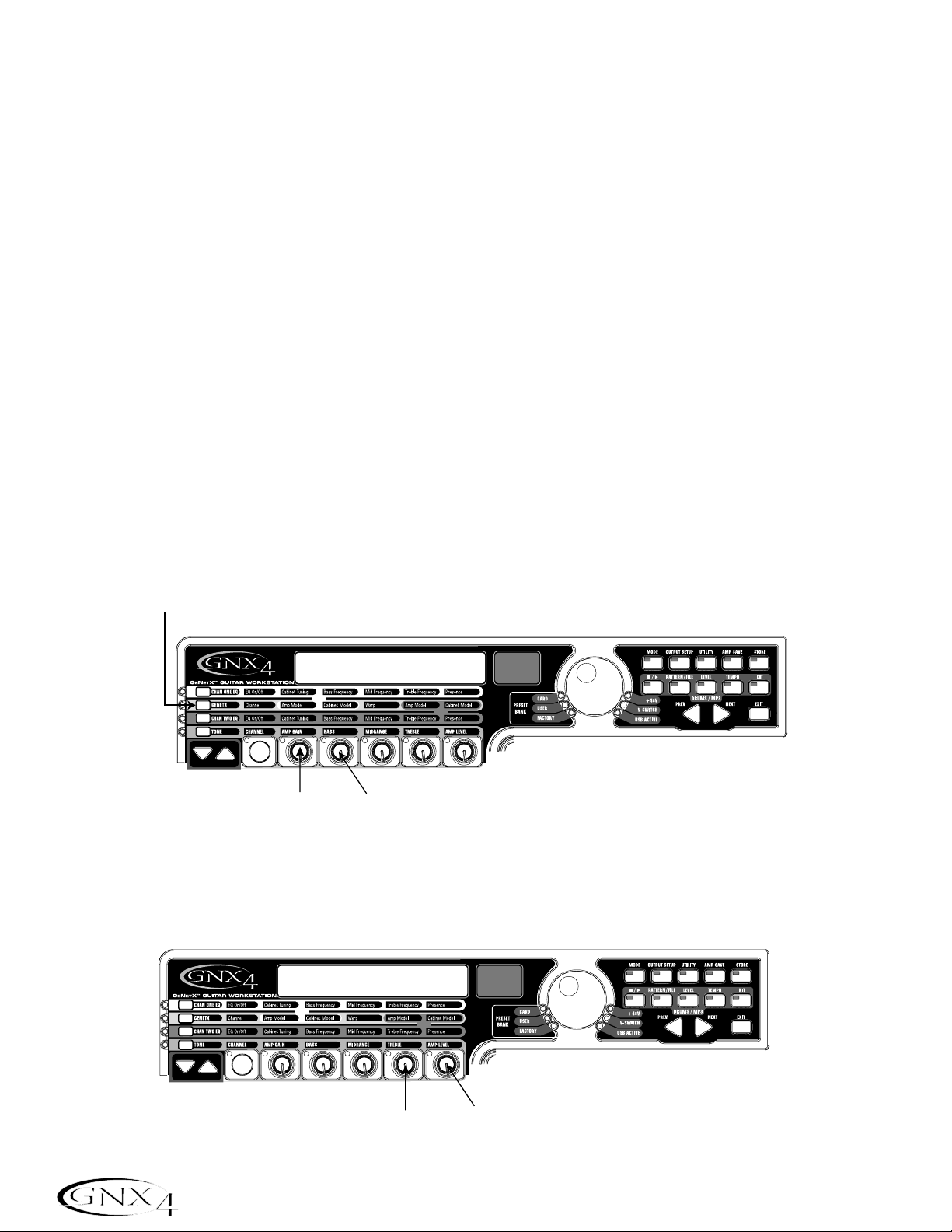
Suppose you wanted to create your own HyperModel™that incorporates the sweet tones of a vintage Tweed
using an American 2x12 cabinet,and the ripping distortion of a Rectified Amp with a British 4x12 cabinet.
Let’s also suppose that you want to be able to toggle between an acoustic guitar simulation and this new
HyperModel with a preset that gives your single coil pickup a humbucker sound,uses no Compression, has a
Noise Gate that opens quickly, a subtle Chorus effect, no Delay, and a little bit of a Hall reverb.The following
guide steps you through the process of creating just that preset in the GNX4.
Selecting a Preset
The first step to create a custom preset of your own is to select a starting point. You can start with any
existing preset,but for this example let’s start with Preset 40. Use the D A T A WHEEL or Footswitches
(when the GNX4 is in either Preset or Stompbox/Control Mode) to select Preset 40.
Create a HyperModel
™
For this example,we are going to use a vintage Tweed amp with an American 2x12 Cabinet, and warp it with
a Rectified Amp using a British 4x12 cabinet.
Select the Channel 1 Amp and Cabinet
To assign the vintage Tweed amp to Channel 1 do the following:
1. Press the GENETX Amp Control button to access each channel’s amp and cabinet models.
2. Rotate Knob 1 until the display reads
TWEED (Tweed).
3. Rotate Knob 2 until the display reads
amer2X12 (American 2x12).
Select the Channel 2 Amp and Cabinet
To assign the Rectified amp to the Channel 2 do the following:
1. Rotate Knob 4 until the display reads
Rectfied (Rectified).
2. Rotate Knob 5 until the display reads
brit4x12 (British 4x12).
50
Creating a Preset
1. Press the GENTEX
Amp Control Button
2. Rotate Parameter 1 Knob
Until Display Reads TWEED
3. Rotate Parameter 2 Knob
Until Display Reads AMER2X12
1. Rotate Parameter 4 Knob
Until Display Reads rectfied
2. Rotate Parameter 5 Knob
Until Display Reads brit4x12
Page 61
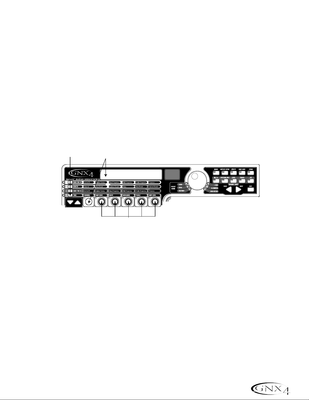
Adjust the Channel 1 Parameters
The Tweed amp that we selected for our Channel 1 assignment uses the factory default settings for the
Gain,EQ, and Level Parameters. Therefore, you may want to change the settings. To access the
Parameters for Channel 1,do the following:
1. Press the TONEAmp Control button.
2. Press the STATUS button three times to select Channel 1’s Parameters. The display will read
ch1
amp
and all the horizontal LEDs will light green indicating that all 5 knobs will adjust Channel 1’s
Parameters.
3. Rotate Knob 1 to adjust the Tweed Amp’s Gain. The range is from
0 to 99.
4. Rotate Knob 2 to adjust the Tweed Amp’s Bass EQ Level (boost/cut). The range is from -12 dB
(
-12) to +12 dB (12).
5. Rotate Knob 3 to adjust the Tweed Amp’s Midrange EQ Level(boost/cut). The range is from -12 dB
(
-12) to +12 dB (12).
6. Rotate Knob 4 to adjust the Tweed Amp’s Treble EQ Level(boost/cut). The range is from -12 dB
(
-12) to +12 dB (12).
7. Rotate Knob 5 to adjust the Tweed Amp’s Level. The range is from
0 to 99.
Adjust the Channel 2 Parameters
Like the Tweed amp in Channel 1,the Rectified amp in Channel 2 may need to be adjusted to suit your
personal taste. To access the Parameters for Channel 2,do the following:
1. Press the STATUS button three times to select Channel 2’s Parameters. The display will read
ch2
amp
and all the horizontal LEDs will light red indicating that all 5 knobs will adjust Channel 2’s
Parameters.
2. Rotate Knob 1 to adjust the Rectified Amp’s Gain. The range is from
0 to 99.
3. Rotate Knob 2 to adjust the Rectified Amp’s Bass EQ Level (boost/cut). The range is from -12 dB
(-
12) to +12 dB (12).
4. Rotate Knob 3 to adjust the Rectified Amp’s Midrange EQ Level(boost/cut). The range is from
-12 dB (-
12) to +12 dB (12).
5. Rotate Knob 4 to adjust the Rectified Amp’s Treble EQ Level(boost/cut). The range is from
-12 dB (-
12) to +12 dB (12).
6. Rotate Knob 5 to adjust the Rectified Amp’s Level. The range is from
0 to 99.
51
Creating a Preset
1. Press the TONE
Amp Control Button
2. Press the Status Button
Until Display Reads CH1 AMP
and All LEDs Light Green
3, 4, 5, Rotate Parameter Knobs to Adjust
6, 7. Channel 1's Gain, EQ Level,
and Amp Level
Page 62

Adjust the EQ/Tune the Cabinets
As an option,you may also want to modify each channel’s EQ center frequencies (Bass,Midrange, and
Treble found in the TONErow) and adjust the resonance for the American 2x12 and the British 4x12
Cabinets. To access the EQ center frequency settings and Cabinet tuning, do the following:
1. Select the amp channel that you would like to edit by pressing either the CHAN ONE EQAmp
Control button or the CHAN TW O EQ Amp Control button.
2. Press the STATUS button to turn the EQ on and off.
3. Rotate Knob 1 to adjust the Cabinet Tuning resonance. The Cabinet Tuning ranges are from -
1™0
(one octave below) to 1™0 (one octave above).
4. Rotate Knob 2 to select the Bass center frequency. The range is from 50 Hz (
50 HZ) to 300 Hz
(
300 HZ).
5. Rotate Knob 3 to select the Midrange center frequency. The range is from 300 Hz (
300 HZ) to 5000
Hz (
5000 HZ).
6. Rotate Knob 4 to select the Treble center frequency. The range is from 500 Hz (
500 HZ) to 8000 Hz
(
8000 HZ).
7. Rotate Knob 5 boosts or cuts the Presence Level. The range is from -12 dB (-
12) to +12 dB (12).
52
Creating a Preset
1. Press the Status Button
Until Display Reads CH2 AMP
and All LEDs Light Red
2, 3, 4, Rotate Parameter Knobs to Adjust
5, 6. Channel 2's Gain, EQ Level,
and Amp Level
1. Press either the CHAN ONE EQ
or CHAN TWO EQ Amp Control Button
3, 4, 5, Rotate Parameter Knobs to Adjust
6, 7. Cabinet Tuning,EQ Center
Frequencies, and Presence Level
2. Press the Status Button
To Turn the EQ On and Off
Page 63

W arping Amp Channels Together
When the Amps and Cabinets in Channel 1 and Channel 2 are dialed in to suit your taste, we can Warp
their characteristics together to create a new HyperModel. To warp the amps do the following:
1. Press the GENETX Amp Control button.
2. Rotate Knob 3 (Warp) knob to blend the Amps and Cabinets together to create a new unique amp.
Save the HyperModel
™
Now that we have designed our own Amp/Cabinet HyperModel, we need to save it to one of the 9 User
HyperModel locations. This allows us to use it in presets. To save the HyperModel,do the following:
1. Press the AMP SAVE button until the display reads
NEW AMP and the first letter (N) is flashing. For
this example, let’s name the HyperModel “Rectweed” (Rectified Tweed).
2. Rotate the DA T A WHEEL to select R as the first letter.
3. Press the NEXT ARROW button to select the next character in the display. Continue using the
DAT A WHEEL and NEXT ARRO W button until the display reads
RECTWeeD.
4. When the display reads
RECTWeeD,press the AMP SAVE button again.
5. Now we need to choose one of the 9 User HyperModel locations. Use the D A T A WHEEL to select
a an empty user location. The display should read
EMPTY (Empty) and the red numeric display should
read
U1 if this is the first HyperModel stored to your GNX4.
6. Press the AMP SAVE button again to save to this Amp location. The display briefly reads
AMP
SaVeD
(Amp Saved) and then returns to the name of the selected preset.
53
Creating a Preset
1. Press the GENTEX
Amp Control Button
2. Rotate Parameter 3 Knob To Warp Amp
and Cabinet Models Together
3. Use Next Arrow Button
To Select Character Locations
NEW AMP
2. Use Data Wheel
to Change
Characters
1. Press the
Amp Save
Button
EMPTY U1
5. Use the Data Wheel
to Select an empty
User or Card Amp Location
4. & 6. Press the Amp
Save Button
Page 64

Select Models for the Preset’s Channels
In the previous steps,we selected a Tweed amp model for the Channel 1 amp and a Rectified amp model
for the Channel 2 amp. Then we warped the two together to create our HyperModel
™
. This
HyperModel is saved as an amp type that we named Rectweed,but it is not currently part of our preset.
In this example preset,we need to be able to toggle between an acoustic guitar simulation and our new
HyperModel. To do this we need to now select the Acoustic model for Channel 1’s amp and Rectweed
for Channel 2’s amp in our preset. This procedure is as follows:
1. Press the GENETX Amp Control button.
2. Rotate Knob 1 until the display reads
ACOUSTic. This is Channel 1’s Model for the preset.
3. Rotate Knob 4 until the display reads
RECTWeeD (our new HyperModel). This is Channel 2’s Model
for the preset. This lets us toggle between these two sounds using the Amp Footswitch (when Preset
Mode is active).
Edit the Preset Effects
The next step to creating our example preset involves editing the effects. To edit the preset, do the
following:
1. Press the EFFECT SELECT DOWN button. The display will briefly read
EDIT and the Matrix LED
in the Wah-Pickup row will light.
2. If the red display reads
WAH On,press the STATUS button once to turn the Wah off (since our
example does not use a Wah).
54
Creating a Preset
1. Press the GENETX
Amp Control button
2. Rotate Knob 1 until
the display reads
acoustic
3. Rotate Knob 4 until
the display reads
Rectweed
wah of
1. Press the Effect
Select Down
Button and the
LED will light
on the Wah-Pickup
effect row
2. If necessary, press the
Status Button to turn the
Wah effect off
Page 65

Select the Pickup Type
In our example preset we use a single coil pickup, but want it to sound like a double coil humbucker.
1. With the Wah-Pickup LED lit, rotate Knob 3 until the display reads
SC>Humb. This makes a single
coil pickup sound like a humbucker.
Turn the Compressor Off
We don’t use compression in our preset so,we need to turn the Compressor off. To turn the
Compressor off,do the following:
1. Press the EFFECT SELECT DOWN button. The Compression LED lights and the display
shows the current status of the Compressor.
2. If the Compressor is on, press the STATUS button until the red display reads off (
Of).
Turn the Whammy™/IPS/Talker™Off
We don’t want Whammy, IPS, or Talker effects in this preset. To turn these effects off,do the
following:
1. Press the EFFECT SELECT DOWN button, and the Whammy/IPS/Talker LED is lit.
2. If the display indicates that one of these effects is active,press the STATUS button until the
display reads off (
Of).
Turn the Stompbox Modeling Off
To turn the Stompbox Modeling off for this preset,do the following
1. Press the EFFECT SELECT DOWN button until the Stompbox LED is lit.
2. If the display indicates that it is active, press the STATUS button until the display reads off (
Of).
55
Creating a Preset
sc>humb
1. Rotate Knob 3 until
the display reads SC>HUMB
Page 66

Adjust the Noise Gate
For our example,we want our Noise Gate to open quickly with a relatively weak signal. This type of
gate uses the Silencer
™
with a low threshold and short attack time. To create this type of Noise Gate,
do the following:
1. Press the AMP FOOTSWITCH to select the Channel 2 Amp (
CH2 AMP), our high gain model.
(The GNX4 must be in Stompbox/Control mode to complete this function.)
2. Press the EFFECT SELECT DOWN button and the Noise Gate’s LED lights.
3. If the display reads off (
Of),press the STATUS button until the display reads on (On).
4. Rotate Knob 1 until the display reads
SILeNCeR for the type of gate.
5. Rotate Knob 2 to set the Threshold to
15 (this may need to be adjusted depending upon your
guitar).
6. Rotate Knob 3 to set the Attack Time to
0 (fast attack).
Select and Adjust the Chorus
Next we wanted to thicken up the sound,by adding a subtle Chorus effect, in the following manner:
1. Press the EFFECT SELECT DOWN button again and the LED in the Chorus/Mod row lights.
2. If the display reads off (
Of),press the STATUS button until the display reads on (On).
3. Rotate Knob 1 until the display reads Chorus (
Chorus) for the effect type.
4. Rotate Knob 2 to set the Chorus Speed to
5.
5. Rotate Knob 3 to set the Chorus Depth to
30.
6. Rotate Knob 4 to set the PreDelay to
1.
7. Rotate Knob 5 to set the Chorus Level to
50.
Turn the Delay Off
To bypass the Delay, do the following:
1. Press the EFFECT SELECT DOWN button until the LED in the Delay row lights.
2. If the display reads on (On),press the STATUS button until the display reads off (Of).
56
Creating a Preset
2. Press the Status Button to
turn the Chorus/Mod effect on
chorus
1. Press Effect
Select Down
again until the
Chorus/Mod LED
Lights
6. Rotate Knob 4
3. Rotate Knob 1
to select Chorus
4. Rotate Knob 2
to set the Chorus
Speed to 5.
5. Rotate Knob 3
to set the Chorus
Depth to 30.
to set the PreDelay
to 1.
7. Rotate Knob 5
to set the Chorus
Level to 50.
Page 67

Select and Adjust the Reverb
In our example preset we wanted a little bit of Hall Reverb to provide some ambience. To add the
reverb, do the following:
1. Press the EFFECT SELECT DOWN button until the LED in the Reverb row lights.
2. If the display reads off (Of),press the STATUS button until the display reads on (On).
3. Rotate Knob 1 to select Hall (
Hall) for the Reverb Type.
4. Rotate Knob 2 to set the Reverb Predelay to
2.
5. Rotate Knob 3 to set the Reverb Decay to
15.
6. Rotate Knob 4 to set the Reverb Damping to
40.
7. Rotate Knob 5 to set the Reverb Level to
30.
Store the Preset
The last step is to store our changes to a User Preset. If we changed presets or turned the GNX4 off
without storing these settings,it would forget what we had done and revert back to the original preset.
To store the preset,do the following:
1. Press STORE. The first letter in the display begins to flash. Since this is an example preset, let’s name
the preset
examplE.
2. Rotate the DA T A WHEEL until the flashing character in the display is an
E.
3. Press the NEXT button once and the second character begins to flash.
4. Rotate the DATA WHEEL again until the flashing character is an
X. Continue using the Next Arrow
button to select the character location and the D A T A WHEEL to change the characters.
5. Once the Display reads
exampLE,press STORE again. The numbers in the red numeric display are
flashing.
6. Rotate the DATA WHEEL to select 48 as the destination.
7. Press STORE once more to save the preset.
Congratulations! You have successfully created a Preset.
57
Creating a Preset
1. Press Effect
Select Down
again until the
Reverb LED
lights.
2. Press the Status Button to
turn the Reverb on.
Hall
7. Rotate Knob 5
to set the Reverb
Level to 30.
3. Rotate Knob 1
to select Hall
as the Reverb
type.
4. Rotate Knob 2
to set the Reverb
PreDelay to 2.
5. Rotate Knob 3
to set the Reverb
Decay to 15.
6. Rotate Knob 4
to set the Reverb
Damping to 40.
3. Use the Next Arrow Button
to select character locations
Store
2. Use Data Wheel to
change characters
1. Press the Store
Button
Page 68

Storing a Preset
Once you have modified the Amp Models,Cabinet Types, and Effect Parameters,the Store Button LED flashes
indicating you have changed a parameter and need to store the changes to a User Preset location or to a
Compact Flash Card Preset location in order to recall them later. The following steps outline the procedure
for storing a preset:
1.Press the STORE button.The first letter of the preset name begins flashing.
2.Use the DA TA WHEEL to select the alpha-numeric character.
3.Press the NEXT button to select the next character to the right, and the PREV button to select the
previous character to the left.
4.Repeat steps 2 and 3 until you are finished naming the new preset.
5.Press the STORE button again.The current preset location will then flash in the red display.
6.Select the User or Card Preset location using the DAT A WHEEL.
7.Press the STORE
button again to finish.
Copying a Preset
To copy one preset to another preset location, begin by selecting the preset you want to copy,then
follow the steps listed above.
Press EXIT at any time during the procedure to abort the store process.
58
Storing/Copying a Preset
2. Use the Data Wheel to select an
alpha-numeric character
1. Press Store
Numbername
3. Use the Next button
5 Press Store Again5 Press Store Again5 Press Store Again
to select the next
character
5. Press Store Again
NumberNumber
6. Select a User or
Card Preset Using
the Data Wheel
5 Press Store Again5 Press Store Again5 Press Store Again
7. Press Store Again
Page 69

The GNX4’s Footswitches perform different functions specific to the Mode that has been selected. Listed
below are descriptions of each footswitch’s function within each of the three Modes.
Preset Mode - Green
Bank Up Footswitch - Selects the next bank of presets. Pressing and holding this
footswitch scrolls up through banks. When a new bank is selected the 1 through 5
footswitch LEDs will strobe left to right prompting the user to select a preset. If a
preset is not selected within 5 seconds,the GNX4 returns to the currently selected
bank and preset. Pressing and holding both the Bank Up and Bank Down
Footswitches together will temporarily enable both footswitches to navigate through
the GNX4’s drum patterns or user MIDI files and MP3s stored on an optional CF card.
Bank Down Footswitch - Selects the previous bank of presets. Pressing and holding
this footswitch scrolls down through banks. When a new bank is selected the 1
through 5 footswitch LEDs will strobe left to right prompting the user to select a
preset. If a preset is not selected within 5 seconds, the GNX4 returns to the currently
selected bank and preset.Pressing and holding both the Bank Up and Bank Down
Footswitches together will temporarily enable both footswitches to navigate through
the GNX4’s drum patterns or user MIDI files and MP3s stored on an optional CF card.
Footswitch 1 - Selects the first preset in the active bank. A second press puts the
GNX4 into Bypass or selects the previous preset if Preset Bounceback is enabled
(see page 22 for more instructions on the Preset Bounceback function). Pressing
and holding Footswitches 1 and 2 together will enable or disable the Drums/MP3
Sync button in the Recorder Panel.
Footswitch 2 - Selects the second preset within the active bank. A second press puts
the GNX4 into Bypass or selects the previous preset if Preset Bounceback is
enabled (see 22 for more instructions on the Preset Bounceback function).
Pressing and holding Footswitches 1 and 2 together will enable or disable the
Drums/MP3 Sync button in the Recorder Panel. Pressing and holding
Footswitches 2 and 3 together will bypass the GNX4’s effects and amp models.
Footswitch 3 - Selects the third preset in the active bank. A second press puts the
GNX4 into Bypass or selects the previous preset if Preset Bounceback is enabled
(see 22 for more instructions on the Preset Bounceback function). Pressing
and holding Footswitches 2 and 3 together will bypass the GNX4’s effects and
amp models. Pressing and holding Footswitches 3 and 4 together accesses the Tuner.
Footswitch 4 - Selects the fourth preset in the active Bank. A second press puts the
GNX4 into Bypass or selects the previous preset if Preset Bounceback is enabled
(see 22 for more instructions on the Preset Bounceback function). Pressing
and holding Footswitches 3 and 4 together accesses the Tuner. Pressing and
holding Footswitches 4 and 5 together will change the Footswitch Modes.
Footswitch 5 - Selects the fifth preset in the active Bank. A second press puts the
GNX4 into Bypass or selects the previous preset if Preset Bounceback is enabled
(see page 22 for more instructions on the Preset Bounceback function). Pressing
and holding Footswitches 4 and 5 together will change the Footswitch Modes.
59
Footswitch Functions for Modes
AMP CHANNEL
CONTROL A
CONTROL B
CONTROL C
TAP TEMPO
Page 70

Stompbox/Control Mode - Yellow
Preset Up Footswitch - Selects the next preset. Pressing and holding this footswitch
scrolls up through presets. After releasing,the preset that is landed on is loaded and
becomes active. Pressing and holding both the Preset Up and Preset Down
Footswitches together will temporarily enable both footswitches to navigate through
the GNX4’s drum patterns or user MIDI files and MP3s stored on an optional CF card.
Preset Down Footswitch - Selects the previous preset. Pressing and holding this
footswitch scrolls down through presets. After releasing, the preset that is landed on is
loaded and becomes active. Pressing and holding both the Preset Up and Preset
Down Footswitches together will temporarily enable both footswitches to navigate
through the GNX4’s drum patterns or user MIDI files and MP3s stored on a CF card.
Amp Channel Footswitch selects a preset’s amp channel (
Ch1 amp, Ch2 amp,or
warp amp).
This footswitch’s function can be changed in the EXPRESSION
ASSIGN menu. (See page 45 for more information regarding Expression Pedal
Assignment.) Pressing and holding Footswitches 1 and 2 together will enable and
disable the Drums/MP3 Sync button in the Recorder Panel.
Stompbox (Control A) Footswitch turns the Stompbox Modeling on and off. This
footswitch’s function can be changed in the EXPRESSION ASSIGN menu to control
up to 3 parameters at one time and can be setup as a toggle or momentary switch.
(See page 45 for more information regarding Expression Pedal Assignment.)
Pressing and holding Footswitches 1 and 2 together will enable or disable the
Drums/MP3 Sync button in the Recorder Panel. Pressing and holding
Footswitches 2 and 3 together will Bypass the GNX4’s effects and amp models.
Chorus/Mod (Control B) Footswitch turns the Chorus/Mod Effects on and off.
This footswitch’s function can be changed in the EXPRESSION ASSIGN menu to
control up to 3 parameters at one time and can be setup as a toggle or momentary
switch. (See page 45 for more information regarding Expression Pedal
Assignment.) Pressing and holding Footswitches 2 and 3 together will Bypass the
GNX4’s effects and amp models. Pressing and holding Footswitches 3 and 4 together
accesses the Tuner.
Delay (Control C) Footswitch turns the Delay on and off. This footswitch’s
function can be changed in the EXPRESSION ASSIGN menu to control up to 3
parameters at one time and can be setup as a toggle or momentary switch. (See page
45 for more information regarding Expression Pedal Assignment.) Pressing and
holding Footswitches 3 and 4 together accesses the Tuner. Pressing and holding
Footswitches 4 and 5 together will change the Footswitch Modes.
T ap Tempo Footswitch is used for setting the repeat time of the Delay effect. By
tapping this switch repeatedly, you can set the delay to repeat in time with your music.
Pressing and holding Footswitches 4 and 5 together will change the GNX4’s
Footswitch Modes.
60
Footswitch Functions for Modes
AMP CHANNEL
CONTROL A
CONTROL B
TAP TEMPO
CONTROL C
Page 71
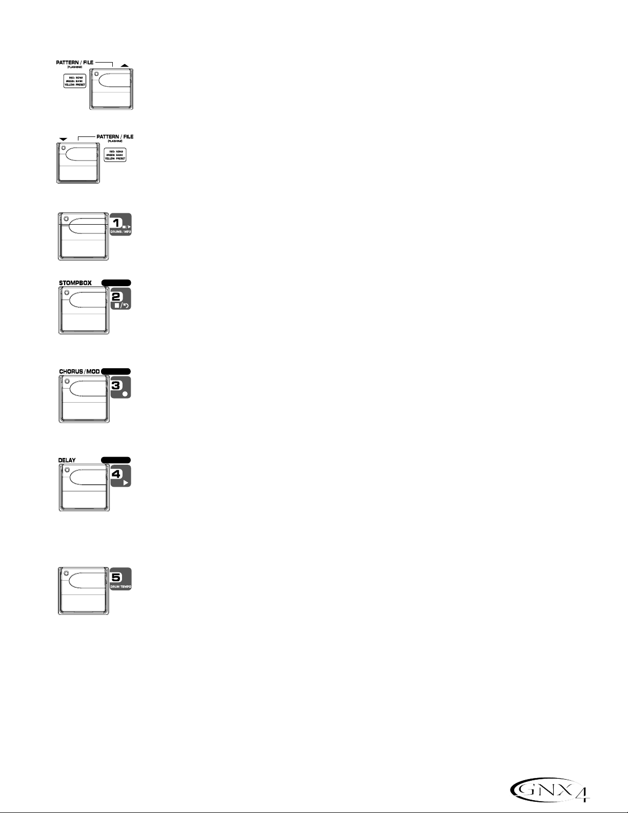
Recorder Mode - Red
Song Up Footswitch - Selects the next song. Pressing and holding both the Song
Up and Song Down Footswitches simultaneously will temporarily enable these
footswitches to navigate through the GNX4’s drum patterns or user MIDI files and
MP3s stored on an optional CF card.
Song Down Footswitch - Selects the previous song. Pressing and holding both the
Song Up and Song Down Footswitches together will temporarily enable these
footswitches to navigate through the GNX4’s drum patterns or user MIDI files and
MP3s stored on an optional CF card.
Drums/MP3 Stop/Play Footswitch - Starts and stops playback of the GNX4’s drum
patterns,or user MIDI files and MP3s in the drum machine file list. Pressing and
holding Footswitches 1 and 2 together will enable or disable the Drums/MP3
Sync button in the Recorder Panel.
Stop/Undo Footswitch - Stops the recorder. Pressing and holding this footswitch
deletes the last track recorded or can delete the current song. Pressing and holding
Footswitch 1 and 2 together will enable or disable the Drums/MP3 Sync button in
the Recorder Panel. Pressing and holding Footswitches 2 and 3 together will
Bypass the GNX4’s effects and amp models.
Record Footswitch - Enables tracks for recording and starts the recorder. It is also
used for setting the JamMan
™
delay loop length and arming and disarming record when
overdubbing onto the active track(s) being recorded. Pressing and holding
Footswitches 2 and 3 together will Bypass the GNX4’s effects and amp models.
Pressing and holding Footswitches 3 and 4 together accesses the Tuner.
Playback Footswitch - Starts playback of the recorder. It is also used for setting the
JamMan delay loop length by putting the first track (or 2 tracks if stereo recording)
that were recorded into playback and automatically arming the next track (or two
tracks if stereo recording) to continue recording the next loop layer. Pressing and
holding Footswitches 3 and 4 together accesses the Tuner. Pressing and holding
Footswitches 4 and 5 together will change the Footswitch Modes.
Drum T empo Footswitch -Tapping this footswitch while the drum machine is on
sets the playback tempo. It must be tapped at least 2 times within 3 seconds to set a
tempo. When a new song is selected from the Recorder Panel,tapping this button
will set the song tempo (which sets the tempo for any drum pattern or MIDI file if
selected) as well. Once a track is recorded in a song,the tempo of a song cannot be
changed by tapping this footswitch until the song has been deleted. You can still tap the
tempo when using the drum machine by itself but not with a previously recorded song.
The Drum Tempo Footswitch also works with MIDI files, however it does not function
when playing MP3s. The Tempo can range from 40 to 240 beats per minute.
Drum T empo is ignored if a song already has tracks recorded and the LED will flash at the song tempo.
Pressing and holding Footswitches 4 and 5 together will change the Footswitch Modes.
61
Footswitch Functions for Modes
AMP CHANNEL
CONTROL A
CONTROL B
CONTROL C
TAP TEMPO
Page 72

The GNX4 is equipped with a Built-in General MIDI Drum Machine and MP3 Player. You can select from
a variety of Factory and User created MIDI drum patterns and drum kits or your own MP3s to play along
with. The GNX4’s Drum Machine/MP3 Player can be set up in different ways as shown below:
Control Panel - Drum Machine/MP3 Player Buttons
(STOP/PLAY)
Press this button to start or stop the drum machine or MIDI File/MP3 playback.
PATTERN/FILE
Press this button to select the Pattern/File library. Use the D A T A WHEEL or PREV and NEXT
buttons to select one of the GNX4’s internal drum patterns. If a CF card is present in the memory
card slot and MP3s and MIDI files are resident on the card, you can select these files for playback as
well. MIDI and MP3 files must be resident in the GNX4>MIDI and GNX4>MP3 directories
respectively on your compact flash card in order for them to be recognized. Please refer to the
Compact Flash Card Usage section of this manual for more information. There are 110 different
drum patterns and 5 metronome settings available including:
Internal Drum Pattern List
LEVEL
Press this button to select the drum machine playback level. Using the DA TA WHEEL or PREV
and NEXT buttons to adjust the volume level of the drum machine or MP3file playback.
TEMPO
Press this button to select the Drum Machine tempo setting. Use the DA TA WHEEL or PREV and
NEXT buttons to adjust the playback speed of the drum or MIDI file being played back. Tempo range
is 40-240 BPM (beats per minute). The TEMPO button has no function when MP3 files are selected
.
KIT
The GNX4 is equipped with several drum kits that cover a variety of music genres. Press this button
to select the drum kit menu. Use the DA TA WHEEL or PREV and NEXT buttons to change
between the different drum kits available. The KIT button has no function when MP3 files are
selected. Listed below are the drum kit types:
Internal Drum Kit List
rock
alterntv
power
heavy
pop
studio
jazzbrsh
techno
8th Beat 1-10
16thBeat 1-5
Rock 1-10
HardRock 1-10
Metal 1-10
Blues 1-5
Funk 1-10
groove 1-5
Country 1-5
R and B 1-5
Jazz 1-5
prog 1-2
prog 6/8 3
prog 7/8 4-5
HipHop 1-5
dance 1-5
Latin 1-5
Reggae 1-5
Percusn 1-5
METR 4/4 1
METR 3/4 1
METR 5/8 1
METR 7/8 1
metronom 5
62
Drum Machine/MP3 Player
Page 73

Footswitch Operation
When the GNX4 is in Recorder Mode,FOOTSWITCH 1 and 5 control drum machine operations.
Drums/MP3 Stop/Play Footswitch - Starts and stops playback of drum patterns or
user MIDI files and MP3s in the drum machine file list. Pressing and holding
Footswitches 1 and 2 simultaneously will enable or disable the Drums/MP3 Sync
button in the Recorder Panel.
Drum T empo Footswitch -Tapping this footswitch while the drum machine is on
sets the playback tempo. It must be tapped at least 2 times within 3 seconds to set a
tempo. When a new song is selected from the Recorder Panel,tapping this button
will set the song tempo (which sets the tempo for any drum pattern or MIDI file if
selected) as well. Once a track is recorded in a song,the tempo of a song cannot be
changed by tapping this footswitch until the song has been deleted. You can still tap the
tempo when using the drum machine by itself but not with a previously recorded song.
The Drum Tempo Footswitch also works with MIDI files, however it does not function
when playing MP3s. The Tempo can range from 40 to 240 beats per minute.
Pattern/File Footswitches - From any of the GNX4’s Footswitch
Modes,you can press and hold the UP/DOWN footswitches
simultaneously to enable them to select any factory drum patterns or any
user MIDI files and MP3s that reside on an optional compact flash card. To
access these patterns and files using the footswitches,do the following:
1.Press and hold the UP/DOWN Footswitches until PAT/FILE appears
in the display. The currently selected pattern or file will then appear in
the display. The UP/DOWN Footswitches will now flash indicating they
are available to select any of the GNX4’s drum patterns, user MIDI files,
or MP3s.
2.Press either the UP or DOWN Footswitch to navigate through the
available patterns and files or press and hold down either footswitch to
scroll through the patterns. You can have the drum machine playing if you
want to hear the files as they are selected.
3.If neither footswitch is pressed within five seconds,the UP/DOWN
Footswitches will stop flashing and return to their normal function
depending on which mode is currently selected.
GNX4 MP3 Demo (Internal)
The GNX4 comes with an internal 30 second MP3 demo that permanently resides in GNX4 memory
(not on a Compact Flash card). To start the demo, remove the Compact Flash card (if one is installed in
your GNX4). Press the PLAY button located on the GNX4’s Recorder Panel and the demo will start
playing. At the end of the song it will automatically loop and playback until you press the Recorder Panel
STOP button. All other Recorder Panel buttons and GNX4 footswitches are effectively disabled when
the MP3 demo is playing.
63
Drum Machine/MP3 Player
AMP CHANNEL
TAP TEMPO
Page 74

This section will cover the GNX4’s inputs and how they are routed for recording internally using Compact
Flash memory and recording on your computer via USB.
GNX4 Inputs and Recorder Routing
The GNX4’s has four audio inputs,the Guitar Input, Mic Input, and Left/Right Line Inputs. It also has a MIDI
input. Each of these inputs can be used to record audio and each has multiple different routing configurations
available. For instance, in a given recording session you may want to record guitar with effects, a dry guitar
only,vocal with or without effects,or both the guitar processing and the line inputs. The GNX4’s flexible
routing lets you record each of these inputs in different combinations and even lets you utilize the GNX4’s
effects processing if desired,giving you a wide variety of options for your particular recording application.
Having an understanding of how the GNX4’s inputs and routing options function is the best way to optimize
your recording experience.
GNX4 Input Sources
The GNX4 has two recorder input selections called Input Sources. Each of these Input Sources offer several
routing configurations for a variety of recording options. The Input Sources are selected using the CF/USB
1-2 SRC and USB 3-4 SRC buttons in the Recorder Panel and the DA TA WHEEL. Up to four tracks of
audio can be recorded on the computer via USB (two tracks maximum to the onboard recorder using an
optional CF memory card). Each Input Source routes a pair of signals (except
MONO FX, MONO ALL,DRY
GUITAR
,DRY MIC,and DRUMS MN which are mono signals) to either the computer or the onboard recorder.
The Input Sources signal combinations are as follows:
(Compact Flash) CF/USB 1-2 Source
stereofx - All input sources that are routed through the GNX4’s effects are sent as a stereo pair to
two available tracks on the onboard recorder or up USB 1 and 2 channels. Drums or MP3,
Dry Mic, and Dr y Line are not recorded.
steroall - All input sources that are routed through the GNX4’s effects, Drums or MP3, Dry Mic , Dry
Line, and Recorder Click Track are sent as a stereo pair to two available tracks on the
onboard recorder or up USB 1 and 2 channels.
mono fx - All input sources that are routed through the GNX4’s effects are summed to mono and sent
to one available track on the onboard recorder or up the USB 1 channel. Nothing is sent up
USB 2 channel. Drums or MP3, Dr y Mic, and Dr y Line are not recorded.
mono all - All input sources that are routed through the GNX4’s effects,Drums or MP3, Dry Mic,Dr y
Line, and Recorder Click Track are summed to mono and sent to one available track on the
onboard recorder or up the USB 1 channel. Nothing is sent up USB 2 channel.
sum+dGTR - All input sources that are routed through the GNX4’s effects are summed to mono and sent
to one available track of the onboard recorder or up the USB 1 channel. Dr y guitar is sent
to the other available track of the onboard recorder or up the USB 2 channel.
sum+mic - All input sources that are routed through the GNX4’s effects are summed to mono and sent
to one available track of the onboard recorder or up the USB 1 channel. Dr y mic signal is
sent to the other available track of the onboard recorder or up the USB 2 channel.
dgtr+mic - Dry guitar signal is sent to one available track of the onboard recorder or up the USB 1
channel. Dr y mic is sent to the other available track of the onboard recorder or up the USB
2 channel.
64
Audio Routing for Recording
Page 75

dry line - Dry Line Left signal is sent to one available track of the onboard recorder or up the USB 1
channel. Dr y Line Right is sent to the other available track of the onboard recorder or up
the USB 2 channel.
dryguitr - Dry Guitar signal is sent to an available track of the onboard recorder or up the USB 1
channel. Nothing is sent up the USB 2 channel.
dry mic - Dry Mic signal is sent to an available track of the onboard recorder or up the USB 1 channel.
Nothing is sent up the USB 2 channel.
drums st - The GNX4 drums playback or MP3 is sent to two available tracks of the onboard recorder
or up the USB 1 and 2 channels.
drums mn - The GNX4 drums playback or MP3 (summed to mono) is sent to one available track of the
onboard recorder or up the USB 1 channel. Nothing is sent up the USB 2 channel.
reamp 1-8/usb - Playback of a pre-recorded,dr y guitar track can be routed back through the GNX4’s
effects processing and recorded back onto two available tracks of the onboard
recorder or back up the USB 1 and 2 busses. Selecting
REAMP 1-8 determines the
source of the dry guitar from the onboard recorder playback. Selecting
REAMPUSB
determines the source of the dry guitar is from the computer. See Re-Amping a
Guitar T rack on pages 82 and 97 for more information how this feature works.
USB 3-4 Source
USB OFF - USB 3 and 4 are disabled.
DGTR+Mic - Dry guitar signal is sent up the USB 3 channel. Dry mic signal is sent up the USB 4 channel.
dry line - Dry Line Left signal is sent up the USB 3 channel and Dr y Line Right signal is sent up the
USB 4 channel.
DRYGuiTR - Dry guitar signal is sent up the USB 3 channel. Nothing is sent up the USB 4 channel.
DRY MIC - Dry mic signal is sent up the USB 3 channel. Nothing is sent up the USB 4 channel.
DRUMS st - GNX4 drum playback is sent stereo up the USB 3 and 4 channels.
DRUMS mn - GNX4 drum playback is sent mono up the USB 3 channel. Nothing is sent up the USB 4
channel.
65
Audio Routing for Recording
Page 76
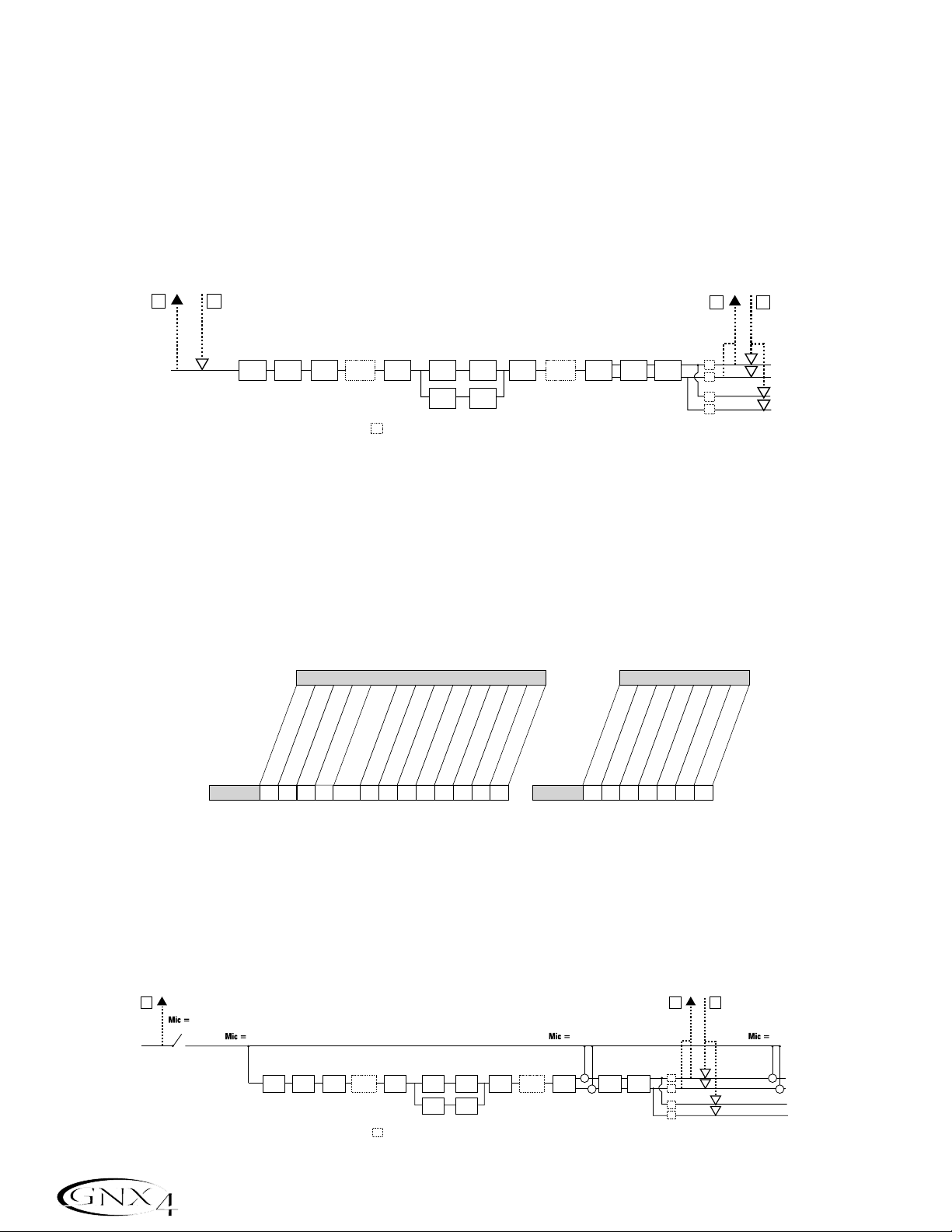
The following diagrams outline how the different input signals are routed through the GNX4 and out to
both the Compact Flash and computer (USB) for recording:
Guitar Signal Routing
The guitar signal is routed from the input through the GNX4’s effects processing and then to the pairs of
outputs. The signal sent to the onboard recorder and up USB can be tapped off either at the input
(CF/USB Send Path A), or at the end of the effects chain (CF/USB Send Path C). Signals recorded
from CF/USB Send Path A can be played back later through the GNX4 for re-amping. See Re-Amping
a Guitar Track on pages 97 for more information on how this feature works.
The guitar signal has two paths in which it is routed to the onboard recorder and up the USB port to the
computer. Path A taps the guitar signal off at the input and sends unprocessed signal to the GNX4’s
recorder and up the USB port. Path C taps the guitar signal at the output of the GNX4 and can include
any effects processing that may be used. Below is a matrix to show where the signal is tapped based on
how the CF/USB 1-2 Source and the USB 3-4 Source settings are configured.
Mic Signal Routing
The mic signal can be routed in different ways through the GNX4. mic off disables the mic input from
being heard,but it still may be recorded using
steroall,Mono all,suM+MIC, DGTR+MIC, or DRY MIC
as the input source. mic dry routes the mic signal around the GNX4’s effects processing and mixes it in
at the outputs.
mic rvb routes the mic signal only through the GNX4’s Delay and Reverb modules.
mic fx routes the mic signal through all of the GNX4’s effects.
66
Audio Routing for Recording
CF/USB Dry
Send Path
Guitar Input
A
B
CF/USB Re-Amp
Return Path
PICKUP SIM WAH COMP
WHAMMY/IPS
STOMPBOX GATE
(except TALKER)
SC
= Speaker Compensation Module
CH 1 AMP
MODELING/
TONE
CH 2 AMP
MODELING/
TONE
CH 1 AMP
CABINET
CH 2 AMP
CABINET
WHAMMY/IPS
(except TALKER)
CHORUS/
MOD
CF/USB Send
DELAY REVERB
Path
C
D
CF/USB Playback
Return Path
SC
SC
SC
SC
XLR Left Output
XLR Right Output
1/4" Left Output
1/4" Right Output
(1/4" USB Playback
disabled in Split Modes)
Routing of Guitar Input to CF/USB
CF/USB 1-2 Source
USB 3-4 Source
stereofx
steroall
Guitar Guitar
CC C, ACA• A •••
C
mono fx
mono all
C
SUM+DGtr
SUM+MIC
DGTR+Mic
dry line
DRYGuiTR
DRY MIC
DRUMS st
drums mn
reamp 1-8/usb
•
usb off
dgtr+mic
dry line
dryguitr
dry mic
• A • A ••
drums st
drums Mn
•
CF/USB Dry
Send Path
E
Mic Input
mic off
mic fx
WHAMMY/IPS
PICKUP SIM WAH COMP
STOMPBOX GATE
(except TALKER)
SC
= Speaker Compensation Module
C
D
CF/USB Playback
Return Path
SC
SC
SC
SC
XLR Left Output
+
XLR Right Output
+
1/4" Left Output
1/4" Right Output
(1/4" USB Playback
disabled in Split Modes)
CH 1 AMP
MODELING/
TONE
CH 2 AMP
MODELING/
TONE
CH 1 AMP
CABINET
CH 2 AMP
CABINET
WHAMMY/IPS
(except TALKER)
CF/USB Send
Path
mic rvb mic dry
+
CHORUS/
MOD
REVERB
DELAY
+
Page 77

The mic signal,as can be seen in the previous Mic Signal Routing diagram, has two paths in which it is
routed to the onboard recorder and up the USB port to the computer. Path E taps the mic signal off at
the mic input and sends unprocessed signal up to the USB port. Path C taps the signal at the output of
the GNX4 and can include any effects processing that may be used. Below is a matrix to show where the
signal is tapped based on how the Mic,CF/USB 1-2 Source,and USB 3-4 Source settings are
configured.
Line Signal Routing
The Line signals,like the mic signal, can be routed in different ways through the GNX4. Line OFF
disables the line inputs from being heard but dry line signal can still be recorded using steroall,Mono
all
,and dry line as the input source. LINE DRY routes the left and right line signals around the
GNX4’s effects processing and mixes them in at the left and right outputs respectively.
line rvb routes
the line signal only through the GNX4’s Delay and Reverb modules.
LINE FX sums the left and right
input signals together and then routes this signal through all the GNX4’s effects.
The line input signals,as can be seen in the previous Line Signal Routing diagram, has two paths in which
they are routed to the onboard recorder and up the USB port to the computer. Path F taps the line
input signals off at the line input and sends unprocessed signal to the GNX4’s recorder and up the USB
port. Path C taps these signals at the output of the GNX4 and can include any effects processing that
may be used. Below is a matrix to show where the signal is tapped based on how the Line,
CF/USB 1-2 Source,and USB 3-4 Source settings are configured.
67
Audio Routing for Recording
Routing of Mic Inputs to CF/USB
Mic
mic off
mic dry
mic RVB
MIC FX
CF/USB 1-2 Source
stereofx
steroall
• E • EE••E • •
E
•
• E • EE••E ••
E
•
C
C
C, E
C, E
C
C
SUM+DGtr
MONO all
MONO fx
C, E
C, E
SUM+MIC
DGTR+Mic
dry line
C C, E E ••E ••
C C, E E ••E ••
DRYGuiTR
DRY MIC
DRUMS st
reamp 1-8/usb
Drums mn
•
•
•
•
Mic
mic off
mic dry
mic RVB
MIC FX
• E ••E •
• E ••E •
• E ••E •
• E ••E •
usb off
dgtr+mic
dry line
USB 3-4 Source
dryguitr
dry mic
drums st
drums mn
•
•
•
•
F
USB Dry
Send Path
Line Left
Line Right
line off
line fx line rvb
PICKUP SIM WAH COMP
+
WHAMMY/IPS
(except TALKER)
SC
CH 1 AMP
STOMPBOX GATE
MODELING/
TONE
CH 2 AMP
MODELING/
TONE
= Speaker Compensation Module
CH 1 AMP
CABINET
CH 2 AMP
CABINET
WHAMMY/IPS
(except TALKER)
CHORUS/
+
MOD
+
USB Send
DELAY
C
Path
SC
REVERB
SC
SC
SC
D
USB Playback
Return Path
line dry
XLR Left Output
+
XLR Right Output
+
1/4" Left Output
1/4" Right Output
(1/4" USB Playback
disabled in Split Modes)
Routing of Line Inputs to CF/USB
Line
line off
line dry
Line RVB
line FX
CF/USB 1-2 Source
stereofx
steroall
• F • ••F ••• •
F
•
• F • ••F ••••
F
•
C
C
C, F
C, F
C
C
MONO all
MONO fx
C, F
C, F
C, F
C, F
SUM+DGtr
SUM+MIC
DGTR+Mic
dry line
DRYGuiTR
DRY MIC
DRUMS st
C • F ••••
• F ••••
C
reamp 1-8/usb
Drums mn
•
•
•
•
Line
LINe off
LINe dry
LINe RVB
LINe FX
••F •••
••F •••
••F •••
••F •••
usb off
dgtr+mic
dry line
USB 3-4 Source
dryguitr
dry mic
drums st
drums mn
•
•
•
•
Page 78

The GNX4’s on-board 8-track digital recorder is the easiest,friendliest multi-track recorder you have ever
used. Rather than having to understand all the mechanics of recording,the GNX4’s recorder is designed to
be virtually hands-free, meaning all you have to do is press a footswitch to get your ideas recorded. The
GNX4 recorder also features a recorder panel interface with standard transport controls,8 track buttons,
Pan,Level, and Master Level buttons for controlling and mixing your projects. Other functions include Time
Remaining,Song Setup, and Input Source buttons which are used for setting up what input source you want
to record or what MP3 or MIDI file you want to use in a song. There are also Record/Playback meters which
let you monitor the levels as you create your song.
Since there is no onboard recording memory,you must first insert an optional Compact Flash (CF) memory
card into the card slot on the rear panel to begin recording tracks. The GNX4 supports most CF cards but
obviously,the larger the card size, the more recording time is available. (See the Using Compact Flash
Memory Cards section on page 75 for memory specifications.)
Recorder Control and USB/Signal Routing Panel
The recorder panel is divided into 12 basic sections:
1. METERS –These two meters show the level of tracks being recorded (REC LEVEL meter) and the
GNX4’s recorder playback level (PLAY LEVEL meter).
2. DISPLAY – There are 2 different displays on the GNX4’s recorder panel
a. SONG –A Song is a group of recorded tracks that are combined to create songs or
loops. This display shows the selected Song or Loop for recording and playback.
b.TIME – This display shows elapsed time of recorded material of the current Song when
the recorder is playing back tracks. When the REMAIN button is on, it will
display the amount of recording time left in memory when the recorder is
stopped.
68
The GNX4’s 8-Track Recorder
1
(a)
2
(b)
3
4
6
7
5
12 (a, b, c, d)
12
8
9
10
12 (e, f, g)
11
Page 79

3. TRANSPORT –The 6 transport buttons just below the displays are used for the record, playback,and
search functions of recorded material. They include STOP, RECORD, PLAY,
REWIND,FAST FORWARD,and UNDO.
4.TRACKS – A Track is an individual memor y location in a song that you record audio to. The GNX4 has
eight individual tracks that can be recorded to.
5. DRUMS/MP3 – This button is used to start the GNX4’s drum machine when the recorder begins
playing. When the button is lit green, the drum machine will playback the pattern or
MIDI file selected in the Song Setup menu. When this button is lit yellow, an MP3 file has
been selected in the Song Setup menu to start playing when the recorder begins playing.
(See the Song Setup section on page 70.) When this button is lit red, the selected
pattern,MIDI file , or MP3 file can be recorded to a track if one of the proper recorder
sources is selected. (See the (Compact Flash) CF/USB 1-2 Source section on page
64.)
6. LEVEL –Accesses the playback level for each track.
7. PAN – Accesses the pan controls for each track.
8. MASTER –This controls the stereo output playback level of tracks recorded on the Compact Flash card.
9. REMAIN –When this button is enabled, the TIME display shows the remaining recording time available
in track minutes when the recorder is stopped. When the recorder is playing back tracks,the
display shows the amount of time remaining in the current song.
10. CF STORAGE –This button is to be pressed first when files are to be copied to and from the
Compact Flash card and your computer’s hard drive. When this button is engaged, the
compact flash card will appear as a new drive on your computer allowing files to be
transferred back and forth. Since file transferring will use up some USB bandwith,it is
not recommended that you record audio to the computer when this is active.
11. SONG SETUP – Accesses setup options for each song including Click T rack, Tempo,Pre-Roll, Song
Repeat,and more. See more about the Song Setup options in the next section.
12. SHIFT –When this button is lit, the secondar y functions labeled below each button are now active.
a. MIC - Selects the mic input routing menu and how the mic signal is routed through the
GNX4’s effects processing for both recording and performance.
b.LINE - Selects the line input routing menu and how both line inputs are routed through the
GNX4’s effects processing for both recording and performance.
c. CF/USB 1-2 SOURCE - Selects what inputs are to be recorded to the onboard recorder
or up the USB 1-2 channels.
d. USB 3-4 SOURCE - Selects what inputs are to be recorded up the USB 3-4 channels.
e. USB PLAY MIX - Controls the level balance between the GNX4’s processing and the USB
stream played back from your computer.
f. CF/USB 1-2 LVL -A gain/attenuation control to optimize the level of sources being
recorded to the Compact Flash card and up the USB 1-2 channel.
g. USB 3-4 LVL - A gain/attenuation control to optimize the level of sources being recorded
up the USB 3-4 channel.
69
The GNX4’s 8-Track Recorder
Page 80

Song Setup
Before you begin recording your first song,you will want to become acquainted with the recorder Setup
functions. Setup functions include: Drums-MP3 (Pattern/File),Drum/MP3 Level,Tempo,Drum Kit, Click
Track, Pre Roll,Song Repeat,Auto Stop, Quantize, and Format. These functions dictate how the recorder
works for each song. Each song can have these functions setup in different ways so that you can customize
how the recorder works depending on your needs. A Song Setup file is saved off to the Compact Flash card
for each song and is resaved whenever any changes are made.
Drums/MP3 (Pattern/File)
The Drums/MP3 (Pattern/File) setup lets you select one of the GNX4’s drum patterns or an external
MIDI or MP3 file to be played back along with any recorded audio in a given song. This is a useful feature
as it lets you have backing tracks in a song without having to allocate audio tracks to play them. When
the DRUMS/MP3 button is enabled, this setting will override the DRUMS/MP3 Pattern selected in the
Control Panel when the PLAY button is pressed on the recorder. To select a pattern or file that you
would like played back with a song,follow these steps:
1.Press the SONG SETUP button once and the GNX4’s main display will show one of the drum
patterns. For example, the 8th Beat pattern will display as
8th beat.
2.Use the DA TA WHEEL to select a Drum Pattern, MIDI, or MP3 file.
3. When finished, press EXIT.
Drums/MP3 Level
The Drums/MP3 Level setup sets the playback level of the file selected in the Drums/MP3 (Pattern/File)
setup menu. When the DRUMS/MP3 button is enabled in the Recorder Panel and the PLAY button is
pressed on the recorder, this setting will override the DRUMS/MP3 Level button located in the far right
Control Panel. To select a pattern or file that you would like played back with a song,follow these steps:
70
The GNX4’s 8-Track Recorder
2. Use the Data Wheel to
select a Drum Pattern,
MIDI, or MP3 file
3. When finished
press Exit
8th beat
1. Press the Song
Setup button
2. Use the Data Wheel to
adjust the Output Level
of the Drums or MP3 file
3. When finished
press Exit
1. Press the Song
Setup button
drum lvl
Page 81

1.Press the SONG SETUP button until the GNX4’s main display reads drum lvl.
2.Use the DA TA WHEEL to adjust the output level of a Drum Pattern or MP3 file.
3. When finished, press EXIT.
Song Tempo
The Song Tempo setup sets the tempo used by the recorder’s Click Track and the GNX4’s drum machine
during the recording and playback of a song. This tempo should be set before any audio is recorded if the
Click Track or drum machine is to be used as a metronome during recording. When the DRUMS/MP3
button is enabled in the Recorder Panel and the PLAY button is pressed on the recorder,this setting will
override the DRUMS/MP3 Tempo button located in the far right Control Panel. The Song Tempo function
has no control when an MP3 file is selected using the Drums-MP3 (Pattern/File) setup. To set the Song
Tempo,follow these steps:
Begin with the recorder stopped.
1.Press the SONG SETUP button until the GNX4’s main display shows the tempo’s numeric value
measured in beats per minute.For example, 124 beats per minute will display as 124 BPm.
2.Use the DA TA WHEEL to adjust the tempo.
3. When finished, press EXIT.
NOTE: Although the Tempo of a song can be changed after tracks have been recorded, it is
not recommended because previously recorded tracks will not be synchronized with
the tracks recorded after the change. The Recorder Tempo also controls the Drum
Machine tempo when recording or playing a virtual Drum track.
71
The GNX4’s 8-Track Recorder
2. Use the Data Wheel to
adjust the Tempo of the
Drum Pattern
3. When finished
press Exit
124 BPM
1. Press the Song
Setup button
Page 82

Drum Kit
The Drum Kit setup selects the drum kit that the Drum Pattern will use during playback. The Drum Kit
setup has no function if an MP3 is selected. To select a Drum Kit, follow these steps:
Begin with the recorder stopped.
1.Press the SONG SETUP button until the GNX4’s main display shows the currently selected drum kit
being used by the drum machine.
2.Use the DA TA WHEEL to select your desired drum kit.
3. When finished, press EXIT.
Click T rack
The Click Track keeps time when the recorder is recording. When Click Track is enabled, a metronome
plays at the selected song’s tempo while recording. To setup the Click Track, follow these steps:
Begin with the recorder stopped.
1.Press the SONG SETUP button until the GNX4’s main display reads
clicktrk.
2.Use the DA TA WHEEL to turn Click Track on and off.
3. When finished, press EXIT.
72
The GNX4’s 8-Track Recorder
2. Use the Data Wheel to
select a Drum Kit
3. When finished
press Exit
KIT
1. Press the Song
Setup button
clicktrk
1. Press the Song
Setup button
2. Use the Data Wheel to
turn the Click Track on
and off
3. When finished
press Exit
Page 83
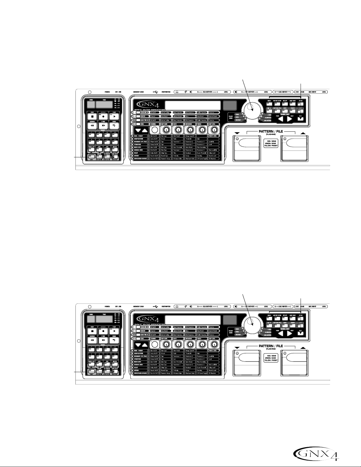
Pre-Roll
Pre-Roll is an amount of time you can have the recorder count off before it actually begins recording.
Pre-Roll can also be used as a count in cue, indicating when the ver y beginning of the song starts. The
GNX4’s Pre-Roll has five settings Off,3,4, 8, or 16 counts. To setup the Pre-Roll function,follow these
steps:
Begin with the recorder stopped.
1.Press the SONG SETUP button until the GNX4’s main display reads
pre-roll.
2.Use the DA TA WHEEL to select the amount of Pre Roll or turn it off. You can select from 3,4, 8, or
16 counts before recording begins.
3. When finished, press EXIT.
Song Repeat
To rehearse with the song you just created, Song Repeat continuously plays the song without having to
press the REWIND and PLAY buttons to re-start it. Each time the song ends during playback, it
automatically restarts from the beginning when this feature is turned on. To enable Song Repeat,follow
these steps:
Begin with the recorder stopped.
1.Press the SONG SETUP button until the GNX4’s main display reads song rpt.
2.Use the DA TA WHEEL to turn Song Repeat on and off.
3. When finished, press EXIT.
73
The GNX4’s 8-Track Recorder
2. Use the Data Wheel to
turn the Pre Roll on
and off
3. When finished
press Exit
Pre-ROll
1. Press the Song
Setup button
2. Use the Data Wheel to
turn the Song Repeat on
and off
song rpt
1. Press the Song
Setup button
3. When finished
press Exit
Page 84

Auto Stop
When trying to conser ve recording memory, or to help automate the recording process,you can use the
recorder’s Auto Stop feature. Begin by recording your longest track first in a new song. Then enable the
Auto Stop feature in the recorder Setup menu. The recorder will now automatically stop at the end of
playback of the longest recorded track while recording new tracks. To enable the Auto Stop follow these
steps:
1.Press the SONG SETUP button until the GNX4’s main display reads
autostop.
2.Use the DA TA WHEEL to turn the Auto Stop feature on and off.
3. When finished, press EXIT.
Quantize
This option is applicable only when the GNX4’s recorder is used as a JamMan™delay looper. The
Quantize function creates perfectly timed loops to the nearest eighth note of a given tempo. Therefore,
if you set a loop length just a little too long to sync with the recorder click track or the GNX4’s drum
machine, the quantize function pulls in the actual loop length to make it sync up exactly with the tempo
you have selected. More about this is found in the Using the GNX4’s JamMan
™
Delay Looper
section on page 87. To setup the Quantize function, follow these steps:
Begin with the recorder stopped.
1.Press the SONG SETUP button until the GNX4’s main display reads
Quantize.
2.Use the DATA WHEEL to turn the quantize function on or off.
3. When finished, press EXIT.
74
The GNX4’s 8-Track Recorder
2. Use the Data Wheel to
turn the Auto Stop on
and off
3. When finished
press Exit
autostop
1. Press the Song
Setup button
quantize
1. Press the Song
Setup button
2. Use the Data Wheel to
turn the Quantize
function on and off
3. When finished
press Exit
Page 85

Format
To quickly erase and format a Compact Flash memory card, the GNX4’s setup menu provides a format
function. If a Compact Flash memor y card is not present in the Compact Flash memory card slot, the
format function is not available. To format a Compact Flash memory card, follow these steps:
1.Press the SONG SETUP button until the display reads
format?. The recorder’s RECORD
button will begin flashing prompting the user to press it to begin formatting.
2.Press the RECORD button. The display reads
SURE?,prompting the user that the next press will
begin the memory erase procedure. To abor t, press EXIT.
3.Pressing the RECORD button a second time will begin the formatting procedure. The GNX4’s
main display reads
format during this time and the GNX4’s buttons and footswitches are disabled
during this procedure.
4. Then GNX4 will display
CF BUSY until the formatting process is complete. You can begin
recording after the GNX4 returns to the preset screen. Do not remove your CF card or turn
the GNX4’s power off while the display reads
CF BUSY or you may lose files.
Using Compact Flash Memory Cards
The GNX4 recorder’s memor y can be increased by using an optional, external Compact Flash memory card.
On the back panel is a card slot for adding memory. The GNX4 supports memor y cards from 32MB
(Megabyte) to 2GB (Gigabyte) in size.
To utilize a Compact Flash memory card in the GNX4, it must be formatted using the FAT16
File format. DigiTech recommends that you format your card in the GNX4 using our internal format
routine. Our internal format routine will configure the card as FAT16. You can also format a card on a PC
using Windows
®
2000 or XP but you MUST select the File System to be FAT (meaning FAT16) instead of
FAT32 and enable the Quick Format option. If a card is formatted using FAT32 and installed into the GNX4
you will be prompted to format it (
FORMAT?). The GNX4 will also prompt the user to format (FORMAT?) a
card that is unrecognizable for any other reason.
NOTE: The GNX4 is compatible with Type I Compact Flash cards only. It is not compatible
with Type II cards or IBM/Hitachi Microdrives
™
.
The table listed below shows the amount of record time each of the currently available cards will provide:
Card Size Recording Time
32MB 6 track minutes
64MB 12 track minutes
128MB 24 track minutes
256MB 48 track minutes
512MB 1 hour and 36 track minutes
1GB 3 hour 12 track minutes
2GB 6 hours 24 track minutes
To use an external memory card with the GNX4, follow these steps:
1.Place the card into the MEMORY CARD slot with the finger grip facing down fully engaging the card.
75
The GNX4’s 8-Track Recorder
Finger Grip
Side Down
Page 86

Let’s Star t Recording!
The GNX4’s recorder can record one or two tracks simultaneously. You can operate the GNX4’s recorder
manually using the Recorder Panel’s buttons, or record hands-free using the GNX4’s footswitches or a
GNXFC (optional).
Selecting an Input Source
To begin recording on the GNX4,it is important to select the source input using the CF/USB 1-2 SRC
button. There are multiple input sources to select from which are outlined in the GNX4 Inputs and
Recorder Routing section on page 64. The source defaults on a new song to Stereo All.
Using the Record and Playback Meters
The GNX4 has two meters located in the upper right corner of the Recorder Panel. The Record meter
can be configured to constantly look at any signals coming into the GNX4 (guitar, mic input,line inputs,
and drum/MP3 playback) and displays their level in reference to the optimum recording level. Before you
begin recording,it is wise to set the levels appropriately to optimize signal to noise. To adjust the source’s
recording levels, follow these steps:
1.Play your guitar or make sure the source you want to record is playing.
2.It is best that the recording level is consistently lighting the -6dB LED on the meter and only lighting
the 0dB LED occasionally.
3.If you need to boost or reduce the level as determined by the Record meter,there are two options:
a.Increase or decrease the level of the source material.
b.Use the GNX4’s CF/USB level compensation control (see steps 4 and 5).
4.If you cannot adjust the source level,press the SHIFT button and then the CF/USB 1-2 LVL button.
5.Use the DATA WHEEL to increase or decrease the level of audio until the optimum level (as
described in step 2) is achieved. The range is from -12 to +24dB.
6.Press the EXIT button.
NOTE: Since what you are hear when you record is not representative of the actual record
level going to the recorder, using the CF/USB 1-2 LVL control to boost or attenuate
levels so as to optimize them for recording will result in an increased or decreased
level during playback versus your monitor level. Use the MASTER button and
DATA WHEEL to adjust playback levels to the desired level as you record.
For more information on Optimizing Microphone and Line Input Levels,see page 13.
76
The GNX4’s 8-Track Recorder
Page 87

Using the GNX4’s Recorder Panel for Recording
Recording a Track
When the GNX4 is powered up and you have installed a Compact Flash card, select the Recorder mode
(Red) using the MODE button found on the Control Panel or by pressing Footswitches 4 and 5
simultaneously. Now the recorder is ready to use. The Song display will read 1,indicating the first song is
selected to record. To begin recording a track,follow these steps:
1.Press the RECORD button. The TRACK 1 button (and TRACK 2 button if recording in stereo)
automatically lights red,indicating it is armed for recording,and the recorder begins recording on this
track. The TIME display begins counting off the recording time.
2.Once recording is complete, press the STOP button. This stops the recording process. The TIME
display shows the elapsed time used, and the TRACK 1 button automatically lights green indicating it is
enabled for playback. (The TRACK 2 button also lights green if recorded in stereo.)
NOTE: Pressing the RECORD button when a track is not armed for recording will force the
GNX4’s recorder to arm and begin recording on the next empty track of a song or
next pair of tracks when stereo sources are selected for recording. You may arm
any 2 track(s) for recording prior to pressing RECORD.
ATTENTION: Do not remove your CF card or turn the GNX4’s power off during the
recording process or you may lose files.
The GNX4’s 8-Track Recorder
77
1. Press the Record button
2. Press the Stop button
Page 88

78
The GNX4’s 8-Track Recorder
Playing Back a Recorded Track
After a track is recorded,playing it back is simple.If you are at the end of the track or the song,press the
PLAY button. The recorder automatically begins playing back the track/song from the very beginning. If
you want to start playback at the beginning of a track or song but are someplace other than the end of
the song,follow these steps:
Begin with the Recorder stopped.
1.Press the REWIND button once to move to the beginning of the song.
2.Press the PLAY button. The newly recorded track is automatically armed in PLAY status (the track
button is lit green) and the track begins playing back.
ATTENTION: Do not remove your CF card or turn the GNX4’s power off while playing
back a track or you may lose files.
Recording Multiple Tracks
After a track has been recorded,you may want to record other tracks (overdub) that will play along with
it. You will want to play the previously recorded track(s) as a monitoring source while recording new
tracks. To add a new track to previously recorded tracks do the following:
1.Press the RECORD button. The next available track for recording automatically lights red,indicating it
is armed to record,and the recorder begins recording on this track from the beginning of the song.
The TIME display begins counting off the recording time. If Autostop is turned on, the recorder will
automatically stop when the longest track playing back is finished. If Autostop is turned off,go to step
2.
2. When recording is complete, press the STOP button.
Setting Track Playback Levels and Panning
After a track has been recorded,you can set the pan and playback level for each track. This is done using
the LEVEL and PAN buttons. This feature is most useful if done while the recording is playing back so
you can hear the changes as they are being made. To set level and pan controls for each track,follow
these steps:
2. Press the Play button
1. Press the Rewind button
Page 89

79
The GNX4’s 8-Track Recorder
Setting Each Track’s Playback Level:
1.Press the REWIND button once to return the song to the beginning.
2.Enable any track(s) you want to playback by pressing their TRACK buttons until they are lit green.
3.Press the PLAY button. Playback of the tracks begins.
4. To adjust the playback level of the tracks,press the LEVEL button once .
5.Press any track button that is playing back. The selected TRACK button will light green and the
other TRACK button LEDs turn off. The main display reads
tkx levl 50 (X = track number).
6. Turn the D A T A WHEEL to adjust this track’s playback level. The range is from
0 to 99.
7.Select other tracks and adjust their playback level by repeating steps 5 and 6.
8.Press the LEVEL button to exit.
Setting Each Track’s Pan:
1.Press the PAN button once. It will light green and the main display will read tkx cntr 0
(X=track number).
2. Turn the D A T A WHEEL to the left to pan the track to the left in the stereo field (
tkx left).
Turn the DA TA WHEEL to the right to pan the track to the right (
tkx rght).
3.Select other tracks and adjust their pan position by pressing the track button and repeating step 2.
4.Press the PAN button again to exit.
Adjusting the Recorder’s Playback Master Level
As more tracks are recorded, the output level will begin to increase. You will notice the Playback
Meter will reach clipping much easier which will cause distortion in the audio being played back. To
compensate for this,the GNX4 recorder has a Master Level to control the overall playback level of the
internal recorder. To adjust the Master playback level,follow these steps:
1.Press the PLAY button to start playback of the song.
2.Press the MASTER button and use the DATA WHEEL to reduce or increase the playback level so
that the PLAYBACK meter level is consistently lighting the -6dB LED on the meter and only lighting
the 0dB LED occasionally.
NOTE: As more tracks are recorded,further adjustments to the Master Level may need to be made
to prevent clipping.
Trak lvl 50
Page 90

Undoing/Erasing a Track
Every track you record may not be a take you want to keep. The GNX4’s recorder features an UNDO
button,that erases the contents of a track. You can undo a track even while recording is in progress,thus
eliminating having to stop and start all the recording procedures again.
WARNING: Deleting a track is permanent and once it is deleted it cannot be retrieved.
Please use the UNDO button with caution.
Using Undo While the Recorder is Stopped
If you have stopped the recorder and decided you were unhappy with the last take, you can Undo
(delete) the track information. To undo the last track you recorded,follow these steps:
1.Press the UNDO button once. The GNX4’s main display reads del trkx, indicating the last
recorded track will be deleted. If you want to delete a different track,press the track button you
want to delete.
2.Press the UNDO button again within 3 seconds to delete the track. If the UNDO button is not
pressed a second time within 3 seconds of the first press,the recorder ignores the undo request
and returns to its normal stopped state.
Using Undo While Recording is in Progress
You can Undo a track while recording is in progress. This eliminates having to stop the recorder
delete the track,rewinding, and having to start over. To undo the track you are currently recording
on,follow these steps:
1.Press the UNDO button once. The GNX4’s main display reads
rerecrd?.
2.Press the UNDO button again within 3 seconds to start re-recording. The display reads
UNDO then
undodone and the recorder returns to the beginning of the song and resumes recording on the
same track. If the UNDO button is not pressed again within 3 seconds of the first press,the
recorder ignores the undo request and recording continues unaffected.
If you don’t want to have the recorder automatically start re-recording when using UNDO,press the
STOP button to stop recording before using the UNDO function.
80
The GNX4’s 8-Track Recorder
del trk1
Page 91

81
The GNX4’s 8-Track Recorder
Changing T rack Status
Each recorded track can be in 1 of 4 states;playback,record,merge, or off. Tracks with recorded material
can be turned on for playback (TRACK button is lit green),armed for recording (TRACK button is lit
red),armed for merging other recorded tracks to it (TRACK button is lit yellow) or turned off (button
is not lit).If a track does not have material recorded on it,it can only be enabled for recording, merge, or
turned off. To change the status of a track, do the following:
1.Press any TRACK button repeatedly until it lights green,red, or yellow. If the button lights green,
there is recorded material present. If the RECORD or PLAY button is pressed the material is played
back. If the button lights red and the RECORD button is pressed, audio will be recorded on this
track. If the button lights yellow,it merges tracks armed for playback,including recorded material
already present on this track.
Punching In/Punching Out
There may be times you want to replace a track section in the middle of a song. Rather than recording
on a new track at the very beginning and wasting recording time with silence,you can “punch in” the
phrase you want to record at a certain point on the track. To punch in record,follow these steps:
1.Arm the track that you want to punch in and record on (the TRACK button turns red).
2.Press the PLAY button. All tracks that are armed for playback and record begin playing, and the
TRACK button armed for recording begins flashing red.
3. When you reach the point in the playback that you want the recording to begin,press the RECORD
button. The TRACK button armed for recording lights solid red and recording begins on this track at
this point.
4. When you are finished recording,press the RECORD button again to disable the track armed for
recording (the track button flashes red) and continue listening to the playback.
Bouncing/Merging T racks
Once you have recorded several tracks, you may want to combine them onto a single track or pair of
tracks to free up recording memory. This is done using the recorder’s Merge function. Merging is
essentially the same as bouncing tracks as you would on old analog 4 and 8-track tape recorders,only
without any signal degradation. You can merge playback tracks with recorded tracks and retain the
recorded material on the tracks you are merging to. This means you don’t need empty tracks to merge
to if all tracks have recorded material on them.
NOTE: Merging tracks is irreversible to the tracks that are merged to. It is wise to make
sure your individual track levels and pans are set prior to merging tracks with recorded
material present. Once tracks are merged,the individual track information cannot be
adjusted.
To merge recorded tracks,follow these steps:
1.Begin with the recorder stopped.
2. Arm the track(s) you want to merge for playback (TRACK buttons lit green).
3.Press the TRACK button(s) you want to merge to until they light yellow. Only a maximum of two
tracks at a time can be selected to merge to.
4.Press the RECORD button. The recorder begins merging the audio from the tracks armed for
playback onto the tracks armed for merge. Once merging has begun, it cannot be stopped until
playback through the entire song is completed.
Page 92

Re-Amping Using the GNX4’s Recorder
Re-amping is a feature that allows you to record a dry, unprocessed guitar track and then play it back through
the GNX4’s effects afterward. This allows you to record a part just once and then experiment with different
amp/cabinet/effect combinations until the sound fits well in the mix. One great thing about using the GNX4’s
re-amp capability is that you can record this unprocessed track while still monitoring your performance
through the GNX4’s processing. This lets you get the feel of hearing the guitar through the amp and effects
while tracking,while only recording the dry guitar. To re-amp a guitar track,follow these steps:
1.Begin with the recorder stopped.
2.Press the SHIFT button on the Recorder Panel.
3. Press the CF/USB 1-2 SRC button on the Recorder Panel.
4. Use the DATA WHEEL to select
DRYGUITR as the source.
5. Press the EXIT button.
6.Use the DA TA WHEEL to select a preset that gives you a good feel for the performance you are about
to record.
7. Press the RECORD button. A new track will arm itself and you can begin recording your performance.
8.When finished, press the STOP button.
9. Press the SHIFT button on the Recorder Panel (if it is not already lit).
10.Press the CF/USB 1-2 SRC button on the Recorder Panel.
11.Use the DATA WHEEL to select
REAMP X (X = the track number you just recorded to).
12.Press the PLAY button.
You will now hear your performance played back through the currently selected preset. Use the DAT A
WHEEL to hear this performance played through different presets. Another re-amping method is to record
a guitar using the amp modeling only,without Chorus/Mod, Delay,or Reverb effects by selecting
MONOALL as
the recording source. You can then select a direct amp and cabinet model upon playback and re-amp through
the GNX4’s effects only.
82
The GNX4’s 8-Track Recorder
Page 93

Hands-Free Recording
The GNX4’s footswitches can perform different functions depending on the mode. (See the Footswitch
Functions for Modes section on page 59 for more information.) When Recorder mode is selected,the
UP/DOWN footswitches are used to select Songs. The 5 numbered footswitches are used to Play Drum
Patterns/MIDI files/MP3s,Stop/Undo, Record,Play,and set Drum Pattern Tempo. Use the Mode button
located in the Control Panel or press Footswitches 4 and 5 simultaneously (until they light red) to select
Recorder mode. This turns your GNX4’s pedalboard into a hands-free remote control for the recorder and
tracks are armed automatically for recording and playback.
Using the RECORD Footswitch to Record a Track
To begin recording a track using the footswitches,follow these steps:
1.Press the RECORD footswitch. The TRACK 1 button (and TRACK 2 button if recording stereo
tracks) automatically lights red,indicating it is armed to record,and the recorder begins recording on
the track. The TIME display begins counting off the recording time.
2. When you are finished recording the track,press the STOP/UNDO footswitch. This stops the
recording process, and the track is saved. The TIME display shows the elapsed time used and the
TRACK 1 button (and TRACK 2 button if recording stereo tracks) is lit green indicating it is now
enabled for playback.
Using the PLAY Footswitch to Play Back a Recorded Track
After a track has been recorded,playing it back is simple.If you are at the end of the track or the song,
press the PLAY footswitch. The recorder automatically begins playing back the track/song from the very
beginning. If you want to start playback at the beginning of a track or song, but are someplace other than
the end of the song,follow these steps:
1.Press the STOP/UNDO footswitch twice. This will rewind to the beginning of the current song.
2.Press the PLAY footswitch. The newly recorded track is automatically armed in PLAY status (track
button is lit green) and the track begins playing back.
Using the Footswitches to Record Multiple Tracks
After a track has been recorded,you may want to record other tracks (overdub) that will play along with
it. You will want to play the previously recorded track(s) as a monitoring source while recording new
tracks. To add a new track to previously recorded tracks do the following:
1.Press the RECORD footswitch. The next available track for recording automatically lights red,
indicating it is armed to record,and the recorder begins recording on this track from the beginning of
the song. The TIME display begins counting off the recording time. If Autostop is enabled in the
Recorder setup,the recorder will automatically stop when the longest track playing back is finished. If
Autostop is turned off,go to step 2.
2. When you are finished recording the track,press the STOP/UNDO footswitch.
83
The GNX4’s 8-Track Recorder
CONTROL A CONTROL B CONTROL C
TAP TEMPOAMP CHANNEL
Page 94

Using the UNDO Footswitch to Erase a Track
If you are not happy with a track you just recorded, no problem. You can easily delete,or Undo the last
recorded track using the GNX4’s footswitches. To Undo a track that was just recorded,follow these
steps:
Using Undo While the Recorder is Stopped
1.Press and hold the STOP/UNDO footswitch once. The GNX4’s main display reads del trkx,
indicating the last recorded track will be deleted.
2.Press the STOP/UNDO footswitch again within 3 seconds to delete the track. If the
STOP/UNDO footswitch is not pressed a second time within 3 seconds of the first press,the
recorder ignores the undo request and returns to its normal stopped state.
Using Undo While Recording is in Progress
You can Undo a track while recording is in progress. This eliminates having to stop the recorder,
rewinding,and having to start over. To undo the track you are currently recording on,follow these
steps:
1.Press and hold the STOP/UNDO footswitch once. The GNX4’s main display reads
rerecrd?.
2.Press the STOP/UNDO footswitch again within 3 seconds to start re-recording. The display reads
undo then undodone and the recorder returns to the beginning of the song and resumes
recording on the same track. If the UNDO footswitch is not pressed again within 3 seconds of the
first press,the recorder ignores the undo request and recording continues unaffected. If you don’t
want to have the recorder automatically start re-recording when using UNDO, press the
STOP/UNDO footswitch to stop recording before using the UNDO function.
Using the Footswitches for Punching In/Punching Out
There may be times you want to replace a track section in the middle of a song. Rather than recording
on a new track at the very beginning and wasting recording time with silence,you can “punch in” the
phrase you want to record at a certain point on the track. To punch in record,follow these steps:
1.Begin with the Recorder stopped.
2.Arm the track that you want to punch in and record on (theTRACK button will light red).
2.Press the PLAY footswitch. Tracks that are armed for playback begin playing,and the TRACK button
armed for recording flashes red.
3. When you reach the point in the playback that you want the recording to begin,press the RECORD
footswitch. The TRACK button armed for recording,lights solid red and recording begins on the
track at this point.
4. When you are finished recording,press the RECORD footswitch to continue listening to playback and
disable the track armed for recording,or press the STOP/UNDO footswitch to stop.
84
The GNX4’s 8-Track Recorder
Page 95
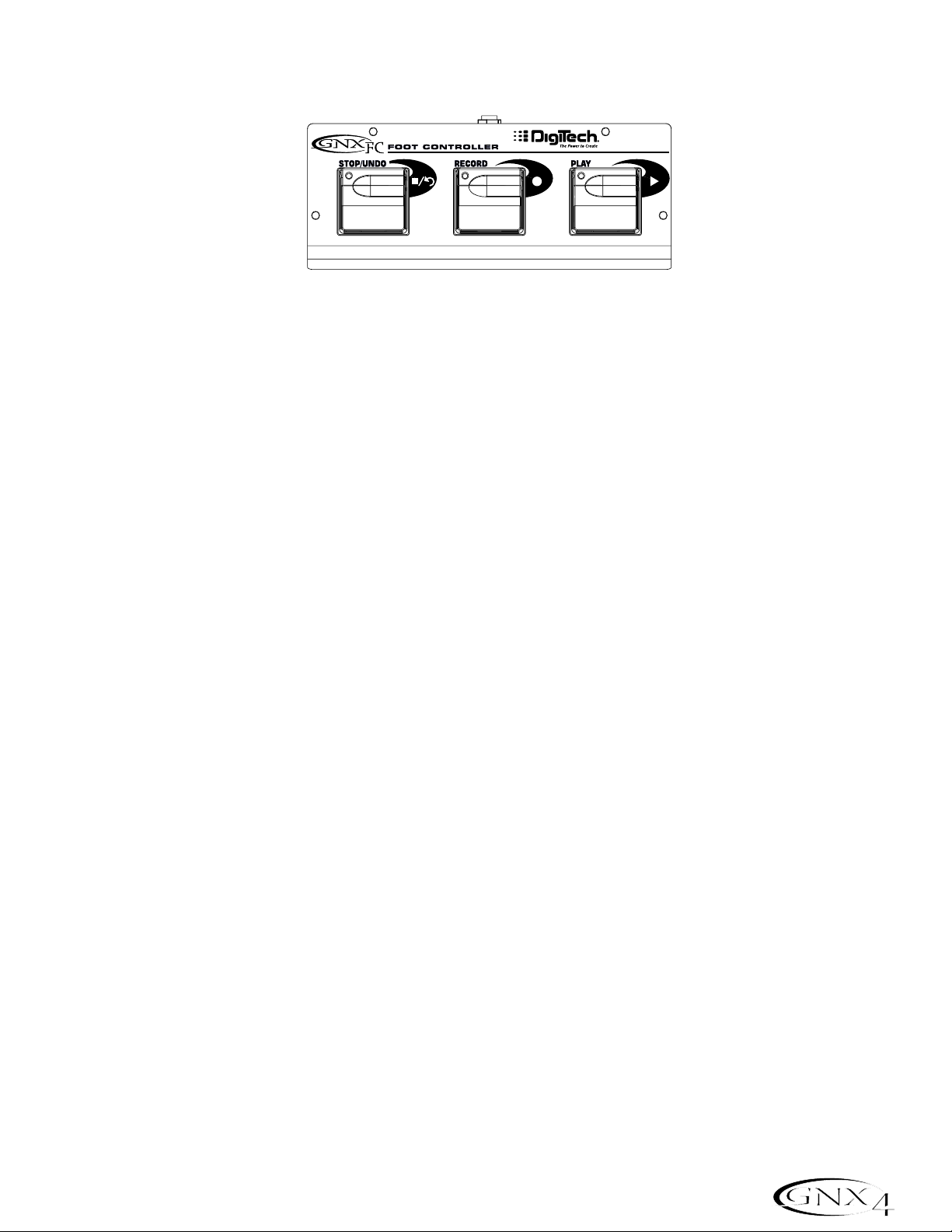
Hands-Free Recording with the GNXFC
The GNX4 is equipped with a footswitch jack that allows you to connect an optional GNXFC for controlling
the GNX4’s recorder. This 3-button footswitch features functions for STOP/UNDO, RECORD,and
PLAY. The GNXFC is also an ideal companion for JamMan
™
(see the Using the GNX4’s JamMan
™
Delay Looper section on page 87 for more information) users as it allows you to leave your GNX4
footswitches setup for changing presets or switching amp channels and effects on and off while the GNXFC
is used for both recording songs and creating loops.
Using the GNXFC to Record a Track
To begin recording a track using the GNXFC footswitches,follow these steps:
1.Press the RECORD footswitch. The TRACK 1 button will automatically light red,which will arm it
to record,and the recorder will begin recording on this track. The TIME display will begin counting off
the recording time.
2.Once recording is completed,press the STOP/UNDO footswitch. This stops the recording process,
and saves the track. The TIME display will show the elapsed time used and the TRACK 1 button will
be lit green indicating it is now enabled for playback.(The TRACK 2 button also lights green if
recorded in stereo.)
Using the GNXFC to Play Back a Recorded Track
After a track has been recorded,playing it back is simple.If you are at the end of the track or the song,
press the PLAY footswitch. The recorder automatically begins playing back the track/song from the very
beginning. If you want to start playback at the beginning of a track or song but are someplace other than
the end of the song,follow these steps:
1.Press the STOP/UNDO footswitch twice. This will rewind to the beginning of the current song.
2.Press the PLAY footswitch. The newly recorded track is automatically armed in PLAY status (track
button is lit green) and the track begins playing back.
Using the GNXFC to Record Multiple Tracks
After a track has been recorded,you may want to record other tracks (overdub) that will play along with
it. You will want to play the previously recorded track(s) as a monitoring source while recording new
tracks. To add a new track to previously recorded tracks do the following:
1.Press the RECORD footswitch. The next available track for recording automatically lights red,
indicating it is armed to record,and the recorder begins recording on this track from the beginning of
the song. The TIME display begins counting off the recording time. If Autostop is enabled in the
Recorder setup,the recorder will automatically stop when the longest track playing back is finished. If
Autostop is turned off,go to step 2.
2. When you are finished recording the track,press the STOP/UNDO footswitch.
85
The GNX4’s 8-Track Recorder
Page 96

Using the GNXFC to Undo/Erase a Track
If you are not happy with a track you just recorded, no problem. You can easily delete,or Undo the last
recorded track using the GNX4’s footswitches. To Undo a track that was just recorded,follow these
steps:
Using Undo While the Recorder is Stopped
1.Press and hold the STOP/UNDO footswitch once. The GNX4’s main display reads del trkx,
indicating the last recorded track will be deleted.
2.Press the STOP/UNDO footswitch again within 3 seconds to delete the track. If the
STOP/UNDO footswitch is not pressed a second time within 3 seconds of the first press,the
recorder ignores the undo request and returns to its normal stopped state.
Using Undo While Recording is in Progress
You can Undo a track while recording is in progress. This eliminates having to stop the recorder,
rewinding,and having to start over. To undo the track you are currently recording on,follow these
steps:
1.Press and hold the STOP/UNDO footswitch once. The GNX4’s main display reads
rerecrd?.
2.Press the STOP/UNDO footswitch again within 3 seconds to start re-recording. The display reads
undo then undodone and the recorder returns to the beginning of the song and resumes
recording on the same track. If the UNDO footswitch is not pressed again within 3 seconds of the
first press,the recorder ignores the undo request and recording continues unaffected. If you don’t
want to have the recorder automatically start re-recording when using UNDO, press the
STOP/UNDO footswitch to stop recording before using the UNDO function.
Using the GNXFC for Punching In/Punching Out
There may be times you will want to record in the middle of a song rather than from the very beginning.
Rather than recording on a new track at the very beginning and wasting recording time with silence, you
will want to “punch in” the phrase you want to record at a certain point on the track and then punch
out. To punch in record do the following:
1.Arm the track you want to punch in record on (TRACK button will light red).
2.Press the PLAY footswitch. Any tracks that are armed for playback will begin playing and the TRACK
button armed for recording will flash red.
3. When you reach the point in the playback that you want the recording to begin,press the RECORD
footswitch. The TRACK button armed for recording will now light solid red and recording will now
begin on this track at this point.
4. When you are finished recording,press the PLAY footswitch to continue listening to playback and
disable the track armed for recording,or press the STOP/UNDO footswitch to stop.
86
The GNX4’s 8-Track Recorder
Page 97

Using the GNX4’s JamMan™Delay Looper
The GNX4’s recorder also doubles as a JamMan Delay Looper. The JamMan is used to create a recording
loop that you can playback with. The JamMan functions are accessed using the GNX4’s footswitches while
they are in Recorder mode. The only difference between regular multi-track recording and looping is the
way you use the footswitches after recording your first track.
When recording multiple tracks for a song,you would normally record your first track,stop, rewind,and then
set up for recording your overdub track. The GNX4’s footswitches provide hands-free operation for these
functions. But when you want to create loops on the fly that you can layer,you want the transition from the
first take to the second and so on to be seamless.
To use the JamMan feature of the GNX4 you must first have the footswitches in Recorder mode. To do this,
press Footswitches 4 and 5 simultaneously until the DOWN/UP footswitches are lit red. If you have
songs already in memory, you must select a new Song to record your loop to. To select a new song,press
the UP footswitch. A new song is defined as a song that has no previously recorded material present on any
of its tracks.
You are now ready to begin recording a loop.
Recording a Loop
Recording a loop is no different than doing multi-track recordings. Here are the steps for creating a loop:
1.Press the RECORD footswitch. The TRACK 1 button automatically lights red,indicating it is armed to
record,and the recorder begins recording on this track. The TIME display begins counting off the
recording time.
2.Just as you reach the end of your take, press the PLAY footswitch. This sets the loop length and
places TRACK 1 into playback. You can listen to what you just recorded, and the TRACK 2 button
will flash red indicating it is now armed and ready to begin recording on.
NOTE: If the RECORD footswitch is pressed instead of the PLAY footswitch after recording
the first pass, recording is disabled and the loop’s length is set. The TRACK 1 button
is still armed for recording (flashing red) but is now playing back what you just
recorded. You can now add material to track 1 rather than record on a new track by
pressing the RECORD footswitch to record on this track again. The new material is
added to existing recorded material. Until the PLAY footswitch is pressed,only
track 1 is available to record on.
87
The GNX4’s 8-Track Recorder
Page 98

Recording Layered Overdubs to your Loop
Adding overdubbed layers to your first loop is easy. After recording your first track and pressing the
PLAY footswitch, TRACK 2 is already armed for recording. To add overdubs to the current loop,follow
these steps:
1.Press the RECORD footswitch. The TRACK 2 button lights solid red and begins recording on this
track.
2. When finished, you can press PLAY to stage the next track for recording or press RECORD to
disable recording and remain on the same track.
If at anytime you are not satisfied with your current take while recording overdubs with your original
loop,you can undo it by pressing the STOP/UNDO footswitch. This erases the contents of a track and
lets you proceed with trying another take without having to stop. To use the UNDO function while
recording a loop, follow these steps:
1.Press the STOP/UNDO footswitch once. The GNX4’s main display reads
rerecrd?.
2.Press the STOP/UNDO footswitch again within 3 seconds to start re-recording. The display reads
undo then undodone and the recorder returns to the beginning of the song and resumes recording on
the same track. If the STOP/UNDO footswitch is not pressed again within 3 seconds of the first
press,the recorder ignores the undo request and recording continues unaffected.
Using Quantize for Seamless Loops
When recording loops,it is important that you set the loop length exactly so that your loop is seamless
from finish to start. Sometimes our timing may not be perfect when pressing the PLAY footswitch to set
the length. The GNX4 provides a Quantize feature that corrects these timing problems to the nearest
eighth note. Quantize looks at the point where you pressed the PLAY footswitch in relation to the
tempo you are using for your loop. Lets say you were recording a four second loop and you pressed the
PLAY footswitch just a little late. No problem,with Quantize enabled, the looper will automatically cut
off the extra recording and give you a perfect four second loop. To enable the Quantize feature,follow
these steps:
1.Begin with the recorder stopped by pressing the STOP/UNDO footswitch.
2.Press the SONG SETUP button and use the PREV/NEXT buttons until the GNX4’s main display
reads:
QUANTIZE.
3.Use the DA TA WHEEL to turn the Quantize feature on and off. Quantize only affects delay loops
and does not affect songs.
4.Press the EXIT button.
88
The GNX4’s 8-Track Recorder
Page 99

Using the GNXFC for Looping
Recording a Loop
To begin recording a loop is no different than when you are doing multi-track recording. You must begin
with a new song in order to create a loop. Press the GNX4’s UP Footswitch (the GNX4’s
footswitches must be in Recorder mode first) or the FFWD button on the Recorder Panel to select a
new song that has not been recorded on. Here are the steps for creating a loop:
1.Press the RECORD footswitch. The TRACK 1 button will automatically light red,which will arm it
to record,and the recorder will begin recording on this track. The TIME display will begin counting off
the recording time.
2.Just as you reach the end of your take, press the PLAY footswitch. This will set the loop length and
place TRACK 1 into playback. You will now begin hearing what you just recorded. You will now see
that the TRACK 2 button is flashing red meaning it is now armed and ready to begin recording on.
You have just successfully recorded you first loop and are now ready to start layering overdubs.
NOTE: If the RECORD footswitch is pressed instead of the PLAY footswitch after recording
the first pass, recording is disabled and the loop’s length will be set. The TRACK 1
button will now be armed for record (flashing red). You will begin hearing playback
of track 1 at this time. If you decide you want to add material to track 1 rather
than recording on a new track,press the RECORD footswitch again to enable
recording on this track again. The new material will now be added to existing
recorded material. Until the PLAY footswitch is pressed,only track 1 will be
available to record on.
Recording Layered Overdubs to Your Loop
To begin adding overdubbed layers to your first loop is easy. Since TRACK 2 is already armed for
recording,press the RECORD footswitch when you are ready to begin recording your overdub.
1.Press the RECORD footswitch. The TRACK 2 button will light solid red and will begin recording on
this track.
2. When finished, you can press PLAY to arm the next track for recording or just press RECORD to
begin adding your next overdub.
If at anytime you are not satisfied with your current take, you can undo it by pressing and holding the
STOP/UNDO footswitch. This will erase the last recorded track and let you proceed with trying
another take without having to stop. (See Using Undo While Recording is in Progress on page 86.)
89
The GNX4’s 8-Track Recorder
Page 100

Drum Machine Recorder Operation
The Drum Machine can be assigned to play a particular pattern,MIDI file, or an MP3 in any song when the
DRUMS/MP3 button on the Recorder panel is enabled. This button will light green if an internal drum
pattern or MIDI file has been selected for playback,or it will light yellow if an MP3 file has been selected.
When using externally created MIDI files or MP3s for use as playback files,the following rules must be
followed in order for these files to work:
• MP3s and MIDI files must be located in their specific folders within the GNX4 folder on the Compact
Flash card. This will ensure that all .mid and .mp3 files can be located and appended to the end of the
factory PATTERN/FILE list. (See page 101 for information regarding Compact Flash File Structure.)
• MP3s must be encoded as stereo,64kb (or greater), 44.1kHz files.
• MIDI files and internal drum patterns cannot be played while an MP3 is being played and vice-versa.
• MIDI files must be Type 0 (Zero) format in order to be recognized by the GNX4.
• Externally created MIDI files can play the internal drum machine if they were recorded using MIDI
Channel 10.
Setting Up Playback Files with a Song
To select a drum pattern, a MIDI file, or MP3 file to be played back when the recorder’s PLAY button is
pressed,follow these steps:
1.Select a new song using the FFWD or REWIND buttons, or using the UP/DOWN footswitches when
they are in recorder footswitch mode.
2.Press the DRUMS/MP3 [play/stop] button in the Control Panel. The drum machine will begin playing.
3.Press the PATTERN button and use the DAT A WHEEL to select which internal drum pattern, MIDI file,
or MP3 file from the list that you want to use with the song.
4.Press the LEVEL, TEMPO,and KIT buttons and use the DA T A WHEEL to set these functions as you
like. Tempo and Kit are unavailable when an MP3 is selected.
5.Press the DRUMS/MP3 [play/stop] button in the Control Panel to stop the drum machine.
6.Press the DRUMS/MP3 button in Recorder Panel until it lights green (drum pattern or MIDI file is
selected) or yellow (MP3 file is selected).
These settings will be automatically saved as part of the song setup for this song once you begin recording. If
you have an existing song in which you want to change the playback file settings,you need to manually edit
these settings in the SONG SETUP menu as follows:
1.Press the SONG SETUP button once. The currently selected pattern being used by the GNX4’s drum
machine will be displayed (New song only). Existing songs may have a different file displayed.
2.Use the DA TA WHEEL to select a new pattern,MIDI file , or MP3 you want associated with the song.
3.Press the NEXT to access the other drum machine menus (level,tempo,kit) and use the DA TA WHEEL
to change these settings. Tempo and Kit are unavailable if any MP3 has been selected.
4.Press the EXIT button.
Once these settings are saved with a song, they will override any the settings changed using the Control
Panel Drum machine button once the song begins playing
Recording Drums
If you want to record the actual drum machine audio rather than just have it sync to recorded tracks, follow
these steps:
1.Press the SHIFT button located on the Recorder Panel.
2.Press the CF/USB 1-2 SRC or USB 3-4 button also located on the Recorder Panel.
90
The GNX4’s 8-Track Recorder
 Loading...