

Page 1
GENETX
GUITAR PROCESSOR
PROCESADOR DE GUITARRA
TM
USER’S GUIDE / MANUAL DE INSTRUCCION
Page 2
I
These symbols are internationally accepted symbols that warn of potential
hazards with electrical products.The lightning flash means that there are
dangerous voltages present within the unit.The exclamation point indicates
that it is necessary for the user to refer to the owners manual.
These symbols warn that there are no user serviceable parts inside the unit.
Do not open the unit. Do not attempt to service the unit yourself.Refer all
servicing to qualified personnel. Opening the chassis for any reason will void
the manufacturer’s warranty. Do not get the unit wet.If liquid is spilled on
the unit, shut it off immediately and take it to a dealer for service .
Disconnect the unit during storms to prevent damage
.
U.K. Mains PlugWarning
A molded mains plug that has been cut off from the cord is unsafe.
Discard the mains plug at a suitable facility.Never under any circum-
stances should you insert a damaged or cut mains plug into a 13
amp power socket.Do not use the mains plug without the fuse cover
in place. Replacement fuse covers can be obtained from your local retailer.Replacement fuses are 13 amps and MUST be ASTA approved to
BS1362.
Safety Instructions
Notice for customers if your unit is equipped with a power cord.
Warning:This appliance must be earthed.
The cores in the mains lead are colored in accordance with the following
code:
Green and Yellow - Earth Blue - Neutral Brown - Live
As colors of the cores in the mains lead of this appliance may not correspond with the colored markings identifying the terminals in your plug, proceed as follows:
•The core which is colored green and y
ellow must be connected to the
terminal in the plug marked with the letter E, or with the earth symbol, or colored green,or gr
een and yellow.
•The core which is colored blue must be connected to the terminal
marked N, or colored black.
•The core which is colored bro
wn must be connected to the terminal
marked L, or colored red.
This equipment may require the use of a different line cord,attachment
plug, or both,depending on the available power source at installation. If the
attachment plug needs to be changed, refer servicing to qualified service
personnel who should refer to the table below.The green/yellow wire shall
be connected directly to the unit’s chassis.
Warning: If the ground plug is defeated,cer
tain fault conditions in the unit
or in the system to which it is connected can result in full line voltage
between chassis and earth ground. Severe injury or death can then result if
the chassis and earth ground are touched simultaneously.
LIVE
E
NEUTRAL
EARTH GND
CONDUCTOR
L
N
BROWN
BLUE
GREEN/YEL
BLACK
Normal Alt
WIRE COLOR
WHITE
GREEN
Warning
For your protection, please read the following:
Water and Moisture:Appliances should not be used near water
(e.g. near a bathtub,washbowl, kitchen sink, laundry tub,in a wet
basement, or near a swimming pool,etc.) Care should be taken so
that objects do not fall and liquids are not spilled into the enclosure
through openings.
Power Sources: The appliance should be connected to a power
supply only of the type described in the operating instructions or as
marked on the appliance.
Grounding or Polarization: Precautions should be taken so that
the grounding or polarization means of an appliance is not defeated.
Power Cord Protection: Power supply cords should be routed so
that they are not likely to be walked on or pinched by items placed
upon or against them, paying particular attention to cords at plugs,
convenience receptacles,and the point where they exit from the
appliance.
Servicing: To reduce the risk of fire or electrical shock, the user
should not attempt to service the appliance beyond that described in
the operating instructions.All other servicing should be referred to
qualified service personnel.
For units equipped with externally accessible fuse receptacle: Replace fuse with same type and rating only.
Electromagnetic Compatibility
Operation is subject to the following conditions:
•This device may not cause harmful interference.
•This device must accept any interference received,including
interference that may cause undesired operation.
•Use only shielded interconnecting cables.
•Operation of this unit within significant electromagnetic fields
should be av
Instrucciones de seguridad
Aviso para los usuarios si su unidad esta equipada con un cable de alimentación.
Precaucion: Esta unidad debe ser conectada a tierra.
Los filamentos del cable de alimentaci
ón están coloreados de acuerdo al
sigiente código:
Verde y Amarillo - Tierra Azul - Neutral Marron - Activo
Dado que los colores del cable de alimentación de esta unidad puede que
no se correspondan con las marcas de color identificativas de su enchufe, haga
lo siguiente :
•El filamento que tiene color amarillo y verde debe ser conectado a la
terminal del conector marcada con la letra E, o con el simbolo de tierra o
de color verde o de color amarillo y verde.
•El filamento con color azul debe ser conectado a la terminal marcada con
una N o de color negro.
•El filamento de color marrón debe ser conectado a la terminal marcada
con una L o de color rojo.
Línea
E
Neutral
Tierra
CONDUCTOR
L
N
Marr
ón
Azul
Verde/Amarillo
Negro
Normal Alt
COLOR CABLE
Blanco
Ver de
Advertencia
Compatibilidad electromagnetica
Esta unidad cumple con las Especificaciones de producto indicada en la
Declaración de Conformidad. Este hace que la unidad etsé sujeta a las
dos condiciones siguientes:
•
etsa unidad no puede producir interferencias molestas ni da
ñinas, y
•
esta unidad debe recibir cualquier interferencia recibida, incluyendo
las que puedan causar errores no deseado. Debe tratar de evitar el
uso de esta unidad dentro decampos electromagnéticos significativos
•
utilice solo cables de interconexión con blindaje.
Los simbolos de aqui arriba están reconocidos internacionalmente como de
advertencia de los riesgos potenciales con aparatos eléctricos. El rayo dentro
de un triángulo equilátero implica que dentro de la unidad existen voltajes
peligrosos. El simbolo de exclamación dentro del triángulo equilátero indica
que es necesario que lel usuario lea el manual de instrucciones de la unidad.
Estos simbolos también le adviertenque dentro de la unidad no hay ninguna
pieza que pueda ser reparada por el propio usuario. No abrael aparato. Nunca
intente hacer ningún tipo de reparación por sus propios medios. Consulte
cualquier posible reparación únicamente a un Servico Técnico cualificado. La
apertura del chasis por cualquier razón anulará la garantia del fabricante.
No permita que la unidad se humedezca. Si cae algún liquido en el aparato,
apáguelo immediatemente y llévelo al distribuidor o servicio técnico.
Desconecte la unidad durante las tormentas para evitar daños.
Aviso Sobre El Enchufe Para U.K.
El uso de un conector de otro cable no es seguro. Descarte este tipo de
conexiones. BAJO NINGUNA CIRCUNSTANCIA DEBE INSERTAR
UN CABLE CORTADO O DAÑADO EN UN ENCHUFE DE
CORRIENTE DE 13 AMP. No utilice un enchufe de corriente sin que
etsé colocado la tapa del fusible. Puede conseguir recambios de estas tapas
de fusible en su tienda local. Los fusibles de recambio son de 13 amps y
DEBEN estar aprobados por la ASTA con el standard BS1362.
Puede que para este aparato necesite usar un cable de alimentación o un
conector distintos, dependiendo de la fuente de alimentación disponible en
su instalación. Si debe cambiar el enchufe, contacte con un técnico cualificado
y que este haga referencia a la tabla siguiente.
El filamento verde/amarillo debería ser conectado directamente a la carcasa
de la unidad.
Precaución : Si se elimina la toma de tierra, determinadas condiciones
de avería de la unidad o del sistema al que esté conectada pueden hacer que
haya cargas de voltaje de linea entre el chasis y la toma de tierra. Esto podriá
producir daños graves o induso la muerte si tocase simultáneamente la
carcasa y la toma de tierra.
AGUA Y HUMEDAD: No utilice este aparato demasiado cerca del
agua (p.e. cerca de una piscina, fregadero, lavadora o en un sótano
húmedo). Evite que pueda caer ningún objeto o líquidos dentro de la
carcasa a tracés de las aberturas.
FUENTE DE ALIMENTACION: Este aparato debe ser conectado a
una toma de alimentación solo del tipo descrito en este manual o
marcado en la propria unidad.
TOMA DE TIERRA O POLARIZACION: Tome las precauciones
necesarias para que la toma de tierra o polarización del aparato no
queden anuladas.
PROTECCION DEL CABLE DE ALIMENTACION: Coloque los
cables de alimentación de tal forma que no puedan ser pisados y que
queden enganchados o aplastados por cosas colocadas sobre o contra
ellos, con un cuidado especial en los receptáculos de entrada y
conectores, y en el punto en el que los cables salen de las unidades.
REPARACIONES : Para reducir el riesgo de incendios o des cargas
eléctricas, el usuario nunca debe tratar de hacer reparaciones en la
unidad fuera de lo descrito en las instrucciones. Debe dirigir cualquier
otra reparación al servicio técnico cualificado.
PARA LAS UNIDADES EQUIPADAS CON RECEPTACULO
DE FUSIBLE ACCESIBLE DESDE EL EXTERIOR: Sustituya el
fusible soo por otro del mismo tipo y características eléctricas.
Page 3

DECLARATION OF CONFORMITY
Manufacturer’s Name: DigiTech
Manufacturer’s Address: 8760 S. Sandy Parkway
Sandy, Utah 84070,
USA
declares that the product:
Product name: GNX2
Note: Product name may be suffixed by the letters EX, EU, JA, and UK.
Product option: all (requires Class II
power adapter that
conforms to the
requirements of
EN60065, EN60742, or
equivalent.)
conforms to the following Product Specifications:
Safety: IEC60065 (1998)
EN 60065 (1993)
EMC: EN 55013 (1990)
EN 55020 (1991)
Supplementary Information:
The product herewith complies with the requirements of the Low Voltage Directive 72/23/EEC and
the EMC Directive 89/336/EEC as amended by
Directive 93/68/EEC.
DigiTech / Johnson
8760 S. Sandy Parkway
Sandy, Utah 84070, USA
Date: May 25, 2001
European Contact:Your local DigiTech / Johnson
Sales and Service Office or
Harman Music Group
8760 South Sandy Parkway
Sandy, Utah
84070 USA
Ph: (801) 566-8800
Fax: (801) 568-7573
DECLARACION DE CONFORMIDAD
Nombre del fabricante: DigiTech
Dirección del fabricante: 8760 S. Sandy Parkway
Sandy, Utah 84070,
USA
declara que el producto:
Nombre del producto: GNX2
Nota: El nombre de este producto puede llevar los sufijos EX, EU, JA y
UK.
Opciones del producto: todas (requiere un
adaptador de corriente
de clase II que cumpla
con los requisitos de
EN60065, EN60742 o
equivalente).
cumple con las siguientes especificaciones de producto:
Seguridad: IEC60065 (1998)
EN 60065 (1993)
EMC: EN 55013 (1990)
EN 55020 (1991)
Información complementaria :
El producto citado anteriormente cumple con los
requisitos de la Directiva de bajo voltaje 72/23/EEC
y con la Directiva EMC 89/336/EEC tal como quedó
enmendada por la Directiva 93/68/EEC.
DigiTech / Johnson
8760 S. Sandy Parkway
Sandy, Utah 84070, USA
Fecha: 25 de mayo de 2001
Contacto en Europa: Su distribuidor y servicio técnico oficial DigiTech/ Johnson o
Harman Music Group
8760 South Sandy Parkway
Sandy, Utah
84070 USA
Tlf: (801) 566-8800
Fax: (801) 568-7573
II
Page 4

IV
Page 5

Introduction 1
Quick Start 2
Making Connections 2
Apply Power 2
Select an Output Mode 2
Select The Target System Setup . .
2
Select a Preset 2
A Guided Tour of the GNX2 3
The Front Panel 3
The Rear Panel 6
Getting Started 7
Making Connections 7
Mono Operation 7
Stereo Operation 7
Direct to a Mixing Console
8
S/PDIF Digital Output 8
Applying Power 8
About the GNX2 9
The Presets 9
Performance Mode 9
Preset Mode 9
FX Mode 9
The Footswitches 10
The Expression Pedal 10
Bypass Mode 10
Tuner Mode 10
Jam-A-Long 10
Learn-A-Lick Mode 11
Rhythm Trainer 11
Editing Functions 13
Editing/Creating a Preset 13
Amp/Cabinet Modeling 13
Amp Models 13
Cabinet Types 13
Editing Amp Models and Cabinet
Types 13
Selecting Amp/Cabinet
Models 14
Adjusting Amp Parameters .
14
Cabinet Tuning 14
Creating HyperModels™ 15
Saving HyperModels™ (Amp
Save) 15
Editing the Effects 15
Storing/Copying a Preset 16
Effects and Parameters 18
Effect Definitions 18
Wah-Pickup 18
Compressor 18
Whammy/IPS 19
Intelligent Pitch Shifting (IPS) 19
Detuning 20
Pitch Shifter 20
Stomp Box Modeling 20
EQ 21
Noise Gate 21
Talker™ 22
Chorus/Mod Effects 22
Chorus 22
Flange 23
Phaser 23
Triggered Flanger 24
Triggered Phaser 24
Tremolo 24
Panner 25
Vibrato 25
Rotary Speaker 25
AutoYa™ 25
Ya Ya ™ 26
SynthTalk™ 26
Envelope Filter 26
Detune 27
Pitch Shift 27
Delay 27
Reverb 28
Tutorial 29
Select a Preset 29
Create a HyperModel™ 29
Select the Green Channel Amp
and Cabinet 29
Select the Red Channel Amp and
Cabinet 29
Adjust the Green Channel
Parameters 30
Adjust the Red Channel
Parameters 30
Tune the Cabinets (optional) 31
Warp the Green and Red
Channels Together 31
Save the HyperModel™ 31
Select Models for the Preset’s
Channels 32
Edit the Preset 32
Select the Pickup Type 32
Turn the Compressor Off . .
33
Turn the Whammy™/IPS Off
33
Turn the Stompbox
Modeling Off 33
Adjust the Noise Gate 34
Turn the Talker™ Off 34
Select and Adjust the
Chorus 34
Turn the Delay Off 35
Select and Adjust the Reverb
35
Store the Preset 35
Other Functions 37
Expression Pedal 37
LFOs 37
Amp Footswitch 38
Expression Parameter Assignment
List 38
Utilities 39
Mono/Stereo Output 40
Target System Setup 40
Volume Pedal Update 40
V-Switch Threshold 40
Expression Pedal Calibration 41
Bank Names 41
MIDI Channel 42
Bulk Dump 42
MIDI Preset Dump 42
User Amp Dump 43
MIDI Mapping 43
MIDI Merge 43
Digital Level 44
Factory Reset 44
GenEdit™ Editor/Librarian 45
PC 45
Mac 45
Appendix 46
Preset List 46
MIDI CC List 47
MIDI Implementation 48
Specifications 48
Block Diagram 49
Warranty 49
Introducción 1
Arranque rápido 2
Conexiones 2
Encendido 2
Selección de un modo de salida 2
Selección de la configuración de
sistema de destino 2
Elección de un preset 2
Un recorrido guiado por el GNX2 3
El panel frontal 3
El panel trasero 6
Incio 7
Conexiones 7
Funcionamiento mono 7
Funcionamiento stereo 7
Conexión directa a una
mesa de mezclas 8
Salida digital SPDIF 8
Encendido 8
Acerca del GNX2 9
Los presets 9
Modo de ejecución9
Modo Preset 9
Modo FX o de efectos 9
Los pedales de disparo 10
El pedal de expresión10
Modo de anulación o bypass 10
Modo de afinación10
Jam-A-Long 10
Modo Learn-A-Lick 11
Entrenador rítmico 11
Funciones de edición 13
Edición/creación de un preset 13
Modelado de amplificador/recinto
acústico 13
Modelos de amplificadores 13
Tipos de recintos acústicos 13
Edición de modelos de amplificadores y tipos de recintos 13
Elección de modelos de
amplificador/recintos 14
Ajuste de parámetros de
amplificador 14
Afinación de recinto acústico 14
Creación de HyperModels™ 15
Almacenamiento de
HyperModels™ (Amp Save) 15
Edición de los efectos 15
Almacenamiento/copia de un preset16
Efectos y parámetros 18
Definición de los efectos 18
Wah-pastilla 18
Compresor 18
Whammy/IPS 19
Modulación de tono inteligente (IPS) 19
Desafinación20
Modulación de tono 20
Modelado de pedal de efectos 20
EQ 21
Puerta de ruidos 21
Talker™ 22
Efectos de chorus/modulación22
Chorus 22
Flange 23
Modulador de fase 23
Flanger por disparo 24
Modulador de fase por dis-
paro 24
Tremolo 24
Panorama 25
Vibrato 25
Altavoz giratorio 25
AutoYa™ 25
Ya Ya ™ 26
SynthTalk™ 26
Envolvente de filtro 26
Desafinación27
Modulación de tono 27
Retardo 27
Reverb 28
Tutorial 29
Elección de un preset 29
Creación de un HyperModel™ 29
Elección del amplificador y recinto
del canal verde 29
Elección del amplificador y recinto
del canal rojo 29
Ajuste de los parámetros del canal
verde 30
Ajuste de los parámetros del canal
rojo 30
Afinación de los recintos
(opcional) 31
Enlace de los canales verde y rojo
juntos 31
Almacenamiento del
HyperModel™ 31
Elección de modelos para los
canales prefijados 32
Edición del preset 32
Selección del tipo de pastilla32
Desactivación del compresor 33
Desactivación del
Whammy™/IPS Off 33
Desactivación del modelado
de pedal de efectos 33
Ajuste de la puerta de ruidos 34
Desactivación del Talker™ 34
Selección y ajuste del
Chorus 34
Desactivación del retardo 35
Elección y ajuste de la reverb 35
Almacenamiento del preset35
Otras funciones 37
Pedal de expresión37
LFOs 37
Pedal de disparo de amplificador 38
Lista de asignación de parámetro
de expresión38
Utilidades 39
Salida Mono/Stereo 40
Configuración de sistema de destino 40
Actualización de pedal de volumen 40
Umbral de V-Switch 40
Calibración del pedal de expresión41
Nombres de bancos 41
Canal MIDI 42
Volcado de datos 42
Volcado de preset MIDI 42
Volcado de amplificador de usuario43
Mapa MIDI 43
Mezcla MIDI 43
Nivel digital 44
Reinicialización a valores de fábrica 44
Editor/biblioteca GenEdit™ 45
PC 45
Mac 45
Apéndice 46
Listado de presets 46
Lista de controladores continuos MIDI 47
Implementación MIDI 48
Especificaciones técnicas 48
Diagrama de bloques 49
Garantía49
V
Table of Contents / Indice
Page 6

Page 7

Introduction
The DigiTech GNX2, is the most advanced guitar processor of its kind. Thanks
to the highly advanced technology provided by GeNetX™, and the extreme
horsepower contained in the Audio DNA™ DSP engine, you now have the
tools to literally create your own guitar amplifier and speaker cabinet models.
All of this power lets you create a sound that is your own. In addition to designing models, the GNX2 has a library full of studio quality effects.
The intuitive user interface makes programming as simple as turning a
knob. However, your time would be well spent by reading through this
User’s Guide with your GNX2 in front of you.
Included Items
Before you tear open the packaging and toss the manual over your
shoulder, please check to make sure the following items have been
included:
• GNX2
• PSS3 Power Supply
• Warranty Card
• User’s Guide
• GenEdit™ Editor/Librarian CD
The utmost care was taken in the manufacturing and packaging your
GNX2. Everything should be included and in perfect working condition. However, if you find anything missing, please contact the factory
at once. Please take a moment to fill out the warranty card. It is your
safeguard in the unlikely event that the GNX2 develops a problem.
Introducción
El DigiTech GNX2 es el procesador de guitarra más avanzado de su clase.
Gracias a la avanzada tecnología ofrecida por GeNetX™ y al gigantesco poder
que alberga la unidad DSP Audio DNA™, ahora tiene la capacidad de crear literalmente el sonido de su propio amplificador de guitarra y recinto acústico.
Todo este potencial le permite crear un sonido que sea tan único y personal
como su música.Además del diseño de sus propios modelos, el GNX2 tiene una
completa biblioteca de efectos con calidad de estudio.
El intuitivo interface de usuario hace que la programación sea tan simple como girar un mando. No obstante, le recomendamos que dedique
unos minutos a leer completamente este manual de instrucciones con
su GNX2 delante.
Elementos incluidos
Antes de despedazar la caja y tirar este manual a un rincón, asegúrese
de que hayan sido incluidos los siguientes elementos:
• GNX2
• Fuente de alimentación PSS3
• Tarjeta de garantía
• Manual de instrucciones
• CD con editor/biblioteca GenEdit™
Hemos puesto el máximo cuidado en la fabricación y embalaje de su
GNX2.Todos los elementos deberían estar dentro de la caja y en perfecto estado operativo. No obstante, si falta alguno de ellos, póngas en
contacto con nosotros inmediatamente.Aproveche también un
momento para rellenar la Tarjeta de Garantía. Ella será su salvavidas
para el improbable caso de que se encuentre con problemas con su
GNX2.
1
Introduction / Introducción
Page 8

Quick Start
The Quick Start section is included for those of you who would rather play
now and read later.
Making Connections
Connect your instrument to the INPUT jack on the rear panel. Connect
the LEFT/RIGHT OUTPUTS to the input(s) of your amplifier(s), power
amp, or mixer.
Apply Power
Turn the OUTPUT knob on the rear panel of the GNX2 all the way
down (fully counter clockwise). Connect the plug of the PSS3 power supply to the POWER jack on the GNX2. Connect the other end of the
PSS3 power supply to an AC outlet and turn the GNX2 POWER switch
on. Turn your amplifier(s) on,and adjust the volume(s) to a normal playing
level. Gradually increase the GNX2’s OUTPUT volume.
Select an Output Mode
Press the UTILITY button and use the DATA WHEEL to select either
the Stereo or Mono output mode.
Select The Target System Setup
The GNX2 needs to know the type of amplification system it will be used
with. After selecting an Output, press the RHYTHM button. The Target
System Setup menu is displayed. Use the DATA WHEEL to select an
amplification system, and press EXIT to return to Performance mode.
Select a Preset
The GNX2 comes with 64 pre-programmed Factory Presets, and 64 User
Presets. From the factory, the User Presets are exact duplicates of the
Factory Presets.This lets you experiment without losing any of the original
presets.
Use the BANK footswitches to select a Bank, and Footswitches 1-4 to
select a preset. The DATA WHEEL can also be used to select a preset.
After you find a preset you like, you can edit it. See Editing and Creating a
Preset page 13.
Arranque rápido
Hemos incluido esta guía de arranque rápido para aquellos que prefieran
empezar a crear primero y leer después.
Conexiones
Conecte su instrumento en la toma Input del panel trasero. Conecte las
Salidas izquierda/derecha a la entrada(s) de su amplificador(s), etapa de
potencia o mesa de mezclas.
Encendido
Gire completamente a la izquierda el mando de salida del panel trasero del
GNX2. Conecte la toma de la fuente de alimentación PSS3 a la entrada
POWER del GNX2. Conecte el otro extremo a una salida de corriente
alterna y coloque el interruptor POWER del GNX1 en la posición on.
Encienda su amplificador(s) y ajuste su volumen a un nivel de ejecución
normal. Aumente lentamente el volumen de salida del GNX2.
Selección de un modo de salida
Para elegir el modo de salida, pulse una vez el botón UTILITY y use la
rueda DATA para elegir el modo de salida Stereo o Mono.
Elección de la configuración del sistema de
destino
El GNX2 necesita saber el tipo de sistema de amplificación con el que lo va a
usar.Tras elegir una salida, pulse el botón RHYTHM.Aparecerá el menú de
configuración de sistema de destino.Use la rueda DATA para elegir un sistema
de amplificación y pulse el botón EXIT para volver al modo de ejecución.
Selección de un Preset
El GNX2 viene con 64 Presets pre-programados en fábrica y 64 Presets de
usuario. Cuando sale de fábrica, los presets de usuario son réplicas exactas
de los presets de fábrica. Esto le permite experimentar sin correr el riesgo
de perder ninguno de los presets originales.
Use los pedales de disparo BANK para elegir un Banco y los Pedales de
disparo 1-4 para elegir entre los distintos Presets.También puede usar la
rueda DATA para elegir los Presets. Una vez que haya localizado el preset
que le guste, puede editarlo.Vea la edición y creación de un preset en la
página 13.
2
Introduction / Introducción
Page 9
A Guided Tour of the GNX2
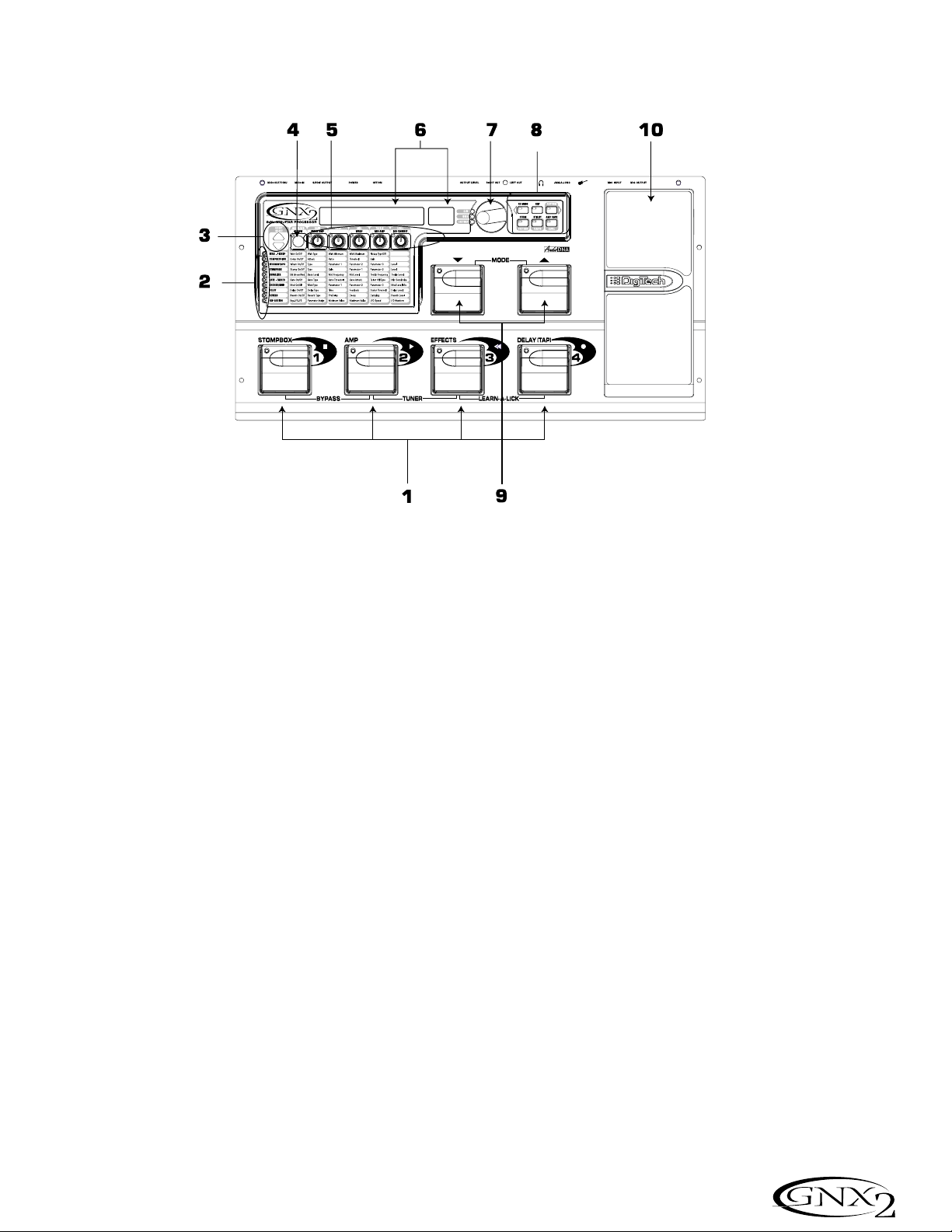
The Front Panel
1. Footswitches 1- 4
Depending on the selected mode, these 4 footswitches select
presets, change amp channels, and turn individual effects on and off.
Bypass, accesses the Tuner,or controls Learn-A-Lick functions.
2. Matrix
The Matrix LEDs light identifying the active effects for the selected
preset in performance mode, or the selected row of effects in edit
mode.
3. Effect Select Buttons
The Effect Select buttons are used together with the Matrix LEDs to
choose the effects you want to edit.
4. Status Button
In performance mode, the Status button selects the Green or Red
Amp Channel. It also activates the amp and cabinet Warping feature
(indicated by a yellow LED next to the Status button). In Edit mode
it turns the selected effect on and off, or selects a controller type for
the expression assignment.
5. Parameter Knobs
In performance mode, these 5 knobs select Amp Models, Speaker
Cabinets, and Warp Models. In Green or Red mode, they adjust the
Amp Gain, EQ and Level of the selected amp channel. In Edit mode,
they adjust the parameters listed in the column directly below each
knob for the selected group of effects.
Recorrido guiado por el GNX1
El panel frontal
1. Pedales de disparo 1 - 4
Dependiendo del modo elegido, estos 4 pedales de disparo se usan
para elegir Presets, cambiar canales de amplificador, activar o
desactivar efectos individuales, anular la unidad, acceder al afinador y
controlar funciones en el modo Learn-A-Lick.
2. Matriz
La Matriz de LEDs le ofrece una indicación visual de los efectos
activos en el preset elegido en el modo de ejecución, o de la fila de
efectos activos en el modo de edición.
3. Botones selectores de efectos
Estos botones selectores de efectos se usan junto con la matriz de
LEDs para escoger los efectos que quiera editar.
4. Botón Status
En el modo de ejecución, este botón se usa para elegir el canal de
amplificación verde o rojo. También activa la función de enlace de
amplificador y recinto (indicada por un piloto amarillo al lado de este
botón). En el modo de edición se usa para cambiar el estado on/off
del efecto elegido, o elegir un tipo de controlador para la asignación
de expresión.
5. Mandos Parameter
En el modo de ejecución, estos 5 mandos se usan para elegir los
modelos de amplificador, recintos acústicos y enlace de modelos.En
el modo verde o rojo, ajustan la ganancia de amplificación, EQ y nivel
del canal de amplificador elegido. En el modo de edición ajustan los
parámetros relacionados en la columna que está justo debajo de
cada uno de los mandos para el grupo de efectos activo.
3
Introduction / Introducción
Page 10

6. Display
The display consists of eight green alpha-numeric characters,and two red
numeric digits. The display provides information for several different functions depending on the selected mode. In Performance mode, the display
shows the selected preset name and number. The display also shows bank
names when changing banks, and momentarily flashes the active amp channel
when the amp channel is changed. In Edit mode, the alpha-numeric display
shows the selected effect’s parameter and value or status. In Tuner mode,
the numeric display shows the note played and the alpha-numeric display
indicates whether the note was sharp or flat. In Learn-A-Lick mode, the
alpha-numeric display shows the selected function and the numeric display
provides an elapsed time for record and playback.
7. Data Wheel
The Data Wheel increases and decreases the selected preset in performance
mode. It increases and decreases the value or status of the selected Utility
or Rhythm function, and scrolls characters in the naming procedure.
8. Mode Buttons
These 6 buttons select GNX2 modes of operation. The Exit button is only
used to exit a function, while the other 5 buttons perform dual functions
dependent on the selected mode of operation. The buttons are labeled as
follows:
FX MODE - The FX Mode button changes the functionality of footswitches
1-4 to toggle individual effects in a selected preset on and off
and change amp channels. When the FX Mode button is lit,
footswitches 1-4 toggle effects on and off and change amp
channels. When the FX Mode button is off, footswitches 1-4
select presets in the current preset bank. This button also
selects the previous character when naming a preset, and the
previous menu in Utility mode. The Mode Down/Up
footswitches functionality changes depending on the status of
the FX Mode button. (see Mode Footswitches section below).
EXIT - Exits all functions and returns to Performance mode.
RHYTHM - The Rhythm button accesses the Rhythm Trainer feature in the
GNX2. When the Rhythm Trainer is selected, the LED lights
and the drum loop begins playing. The bottom row of Mode
buttons can also be used in conjunction with the Data Wheel
to select and edit the Pattern,Tempo, and Level. This button
also selects the next character when naming a preset, and the
next menu in Utility mode.
6. Pantalla
La pantalla consta de seis caracteres verdes alfanuméricos, y dos dígitos
numéricos rojos. Le ofrece información de diversas funciones dependiendo
del modo elegido. En el modo de Ejecución, la pantalla le mostrará el nombre
y número del preset elegido activo.También le mostrará los nombres de los
bancos cuando esté cambiando de uno a otro, y en ella parpadeará momentáneamente el canal de amplificador activo cuando lo cambie. En el modo de
Edición la pantalla alfanumérica le mostrará el parámetro de efecto elegido
en ese momento y su valor o estado. En el modo de Afinador, la pantalla
numérica le mostrará la nota tocada, así como indicaciones de bemol o
sostenido. En el modo Learn-A-Lick, la pantalla alfanumérica le muestra la
función activa mientras que la pantalla numérica le indica el tiempo transcurrido de grabación y reproducción.
7. Rueda Data
La rueda Data aumenta y disminuye el preset activo en el modo de ejecución.Aumenta y disminuye el valor o estado de la función rítmica o de utilidades elegida o va pasando por los distintos caracteres en el proceso de
nombrado.
8. Botones Mode
Estos 6 botones se usan para elegir los diversos modos de funcionamiento
del GNX2. El botón Exit sólo se usa para salir de una función, mientras que
los otros 5 botones tienen funciones dobles dependiendo del modo de funcionamiento elegido. Los botones están indicados de la siguiente forma:
FX MODE - El botón FX Mode cambia la funcionalidad de los pedales de disparo
1-4 para que activen o desactiven efectos individuales en un preset
elegido y cambien canales de amplificación.Cuando el botón FX
Mode está iluminado,los pedales de disparo 1-4 actuarán como
interruptores on/off para los efectos individuales en el preset activo
y cambiarán los canales de amplificación.Si el botón FX Mode está
apagado,los pedales de disparo 1-4 elegirán preset en el banco de
presets activo.Este botón también elige el carácter anterior durante
el proceso de nombrado de un preset,o elige el menú anterior en
el modo de utilidades. La funcionalidad de los pedales de disparo
Mode arriba/abajo cambia dependiendo del estado del botón FX
Mode. (Vea la sección de pedales de disparo de modo más abajo)
EXIT - Sale de todas las funciones y vuelve al modo de ejecución normal.
RHYTHM - El botón Rhythm se usa para acceder a la función de
Entrenador rítmico del GNX2. Cuando está seleccionado este
Entrenador rítmico, el piloto se enciende y el bucle de batería
comienza a reproducirse. Puede usar la fila inferior de botones
de modo junto con la rueda Data para elegir y editar el patrón,
tempo y nivel. Este también elige el siguiente carácter en los
procesos de nombrado de un preset, o el siguiente menú en el
modo de utilidades.
4
Introduction / Introducción
Page 11

STORE - The Store button is used to save your custom edits to the User
presets.The function of this button changes to select Pattern in
Rhythm mode.
UTILITY - The Utility button accesses global functions including Output
Mode,Target System Setup, and MIDI setup.
AMP SAVE - This button stores Amp and Cabinet changes (tone, gain, level,
amp type, cabinet type, warp, or cabinet tuning) as
HyperModels™. This button also selects the level in Rhythm
mode.
9. Mode Footswitches
These footswitches select User Preset Banks, presets,and change
playback speed (Learn-A-Lick), depending on the current mode.
Press the Up and Down footswitches simultaneously to toggle in and
out of FX Mode. When FX Mode is enabled, these footswitches now
navigate through the presets. When FX Mode is disabled, these
footswitches navigate through the User Preset Banks. When LearnA-Lick™ Mode is enabled, these footswitches select the playback
speed of the sampled phrase.
10. Expression Pedal
The Expression Pedal controls effect parameters in real time. Most
GNX2 parameters can be assigned to the Expression Pedal. Applying
extra pressure to the toe of the Expression Pedal switches between
controlling the assigned parameter(s) and controlling the Wah.
STORE - Este botón se usa para almacenar sus ediciones personales en los
presets de usuario. La función de este botón cambia para elegir los
patrones en el modo rítmico.
UTILITY - Este botón le permite acceder a diversas funciones globales
como las de modo de salida, configuración de sistema de destino
y ajustes MIDI.
AMP SAVE - Este botón almacena cambios de los amplificadores y recintos
(sonido, ganancia, nivel, tipo de amplificador, tipo de recinto,
enlace o afinación de recinto) como HyperModels™. Este
botón también elige el nivel en el modo rítmico.
9. Pedales de disparo de modo
Estos pedales de disparo eligen bancos de presets de usuario,presets
y cambian la velocidad de reproducción (Learn-A-Lick) dependiendo
del modo activo. Pulse simultáneamente los pedales de disparo arriba
y abajo para activar o desactivar el modo FX. Cuando este modo
está activo, estos pedales de disparo le permiten navegar por los
distintos bancos de presets de usuario. Cuando está activo el modo
Learn-A-Lick estos pedales eligen la velocidad de reproducción de la
frase musical muestreada.
10. Pedal de expresión
El pedal de expresión controla parámetros de efecto en tiempo real.
La mayoría de los parámetros del GNX2 pueden ser asignados al
pedal de expresión. El aplicar una presión extra en la puntera de este
pedal hará que cambie entre el control del parámetro asignado y el
control del Wah.
5
Introduction / Introducción
Page 12
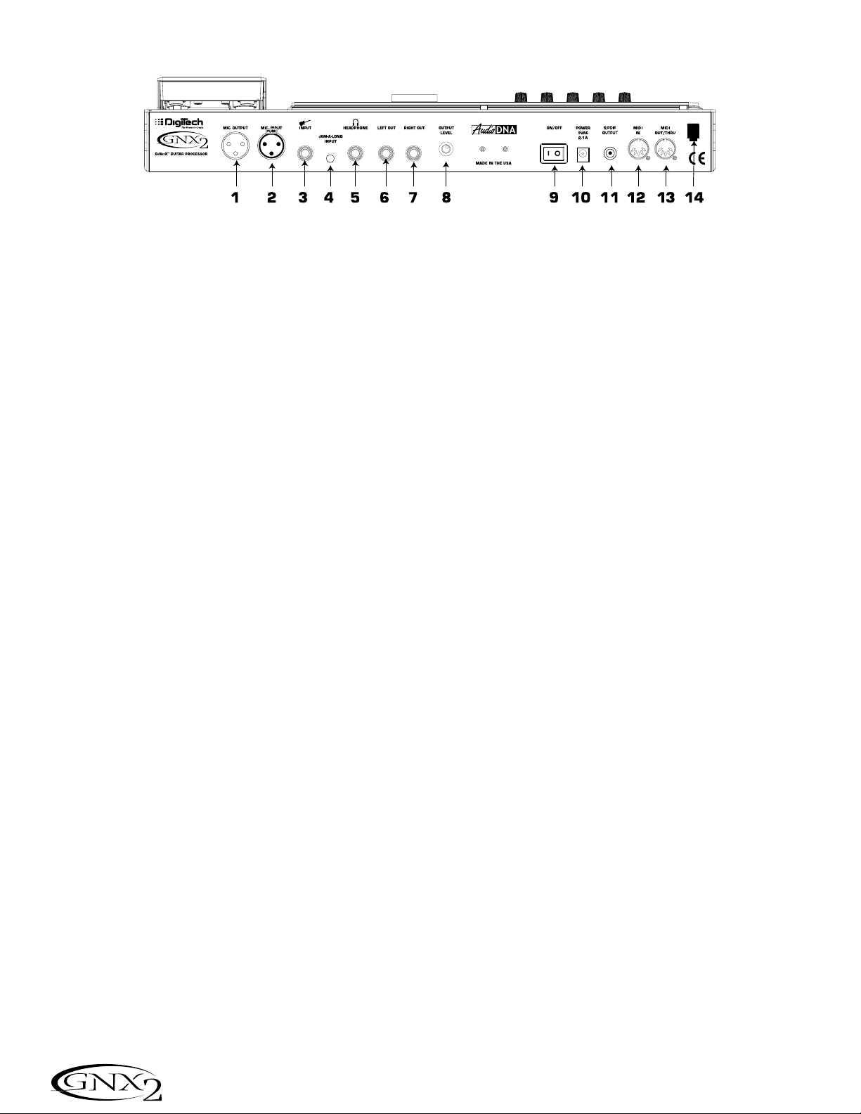
The Rear Panel
1. Mic Output
This XLR jack passes your mic signal to the house mixing console.
2. Mic Input
This XLR jack connects a low impedance mic to the GNX2 that can be used
with the Talker and Vocoder effects. A mic with a cardioid pattern is recommended.
3. Input Jack
Connect your instrument to this jack.
4. Jam-A-Long Jack
Use a 1/8” stereo plug to connect this jack to the output of a tape or CD player. This lets you play along with the music, or record a musical passage.
5. Headphone Output
Connect stereo headphones to this jack. Be sure to set the Target System
Setup mode to Direct when listening through Headphones (see page 40 for
more information on selecting the Target System Setup). Do not connect a
mono plug to this jack, because you may damage the output driver.
6. Left Output
Connect to the input of an amplifier, input of a power amp, or line input of a
mixing console.
7. Right Output
Use this jack in conjunction with the Left Output for stereo applications.
Connect to the input of a second amplifier, or the right input of a stereo power
amp.
8. Output Level
Controls the overall volume level of the GNX2.
9. Power Switch
Turns the power on and off.
10. Power Input
Connect only the provided DigiTech PSS3 power supply to this jack.
11. S/PDIF Output
This is the GNX2’s digital output. The signal at this output is in a stereo digital
format, and is to be connected to a digital S/PDIF input such as those found on
digital recording devices.
NOTE: Do not connect the S/PDIF output to analog auxil-
iary, CD, phono, or tape inputs on consumer electronic
devices. It is not compatible with these inputs.
Panel trasero
1. Salida de micro
Esta clavija XLR pasa su señal de micro a la mesa de mezclas principal.
2. Entrada de micro
Este conector XLR conecta un micro de baja impedancia al GNX2 para que lo
use con los efectos Talker y Vocoder. Le recomendamos que use un micrófono
con un patrón de captación cardioico.
3. Conector de entrada
Conecte su instrumento a esta entrada.
4.Toma Jam-A-Long
Use un conector stereo de 3,5mm para conectar esta toma con la salida de su
pletina o reproductor CD. Esto le permite improvisar junto con la música, o
grabar un pasaje musical.
5. Salida de auriculares
Conecte unos auriculares stereo a esta salida.Asegúrese de ajustar el modo de
configuración de sistema de destino a Direct cuando use los auriculares (vea en
la página 40 más información acerca de esto). No conecte una clavija mono a
esta salida ya que eso podría dañar el cabezal de salida.
6. Salida izquierda
Conecte esta salida a la entrada de un amplificador, la entrada de una etapa de
potencia, o la entrada de línea de una mesa de mezclas.
7. Salida derecha
Use esta salida junto con la salida izquierda para aplicaciones stereo.Conecte
esta salida a la entrada de un segundo amplificador, o a la entrada derecha de
una etapa de potencia stereo.
8. Nivel de salida
Controla el nivel de volumen global del GNX2.
9. Interruptor Power
Enciende o apaga la unidad.
10. Entrada Power
Conecte a esta toma solo la fuente de alimentación DigiTech PSS3 incluida.
11. Salida S/PDIF
Esta es la salida digital del GNX2. La señal que hay en esta salida es en formato
stereo digital, y debe ser conectada a una entrada S/PDIF como la que puede
encontrar en algunas unidades de grabación digital.
NOTA: No conecte la salida S/PDIF a entradas auxiliares, CD,
phono o de cinta de aparatos electrónicos. Las señales de esta
salida no son compatibles con esas entradas.
6
Introduction / Introducción
Page 13
12. MIDI In
This jack receives all incoming MIDI data. Connect this jack to the MIDI out of
a computer, sequencer, MIDI controller, or MIDI storage device.
13. MIDI Out/Thru
This jack sends MIDI data from the GNX2. Connect this jack to the MIDI in of
a computer, or external MIDI recording device. When enabled, MIDI Thru sends
the same information the GNX2 received at the MIDI In.
14. Strain Relief
This secures the power cord and to help prevent it from disconnecting during a
performance.
Getting Started
Making Connections
The GNX2 has several different connection options. You can run mono into an
amp or power amp, stereo into two amps or a stereo power amp, direct into a
mixing console, or any combination of these. Before connecting the GNX2,
make sure both the GNX2 and the amplifier are OFF. The following diagrams
show some examples.
NOTE:The type of amplification system the GNX2 will be used with
should be selected at the Target System Setup of the Utility menu.
See page 40 for more information about selecting the Target System
Setup.
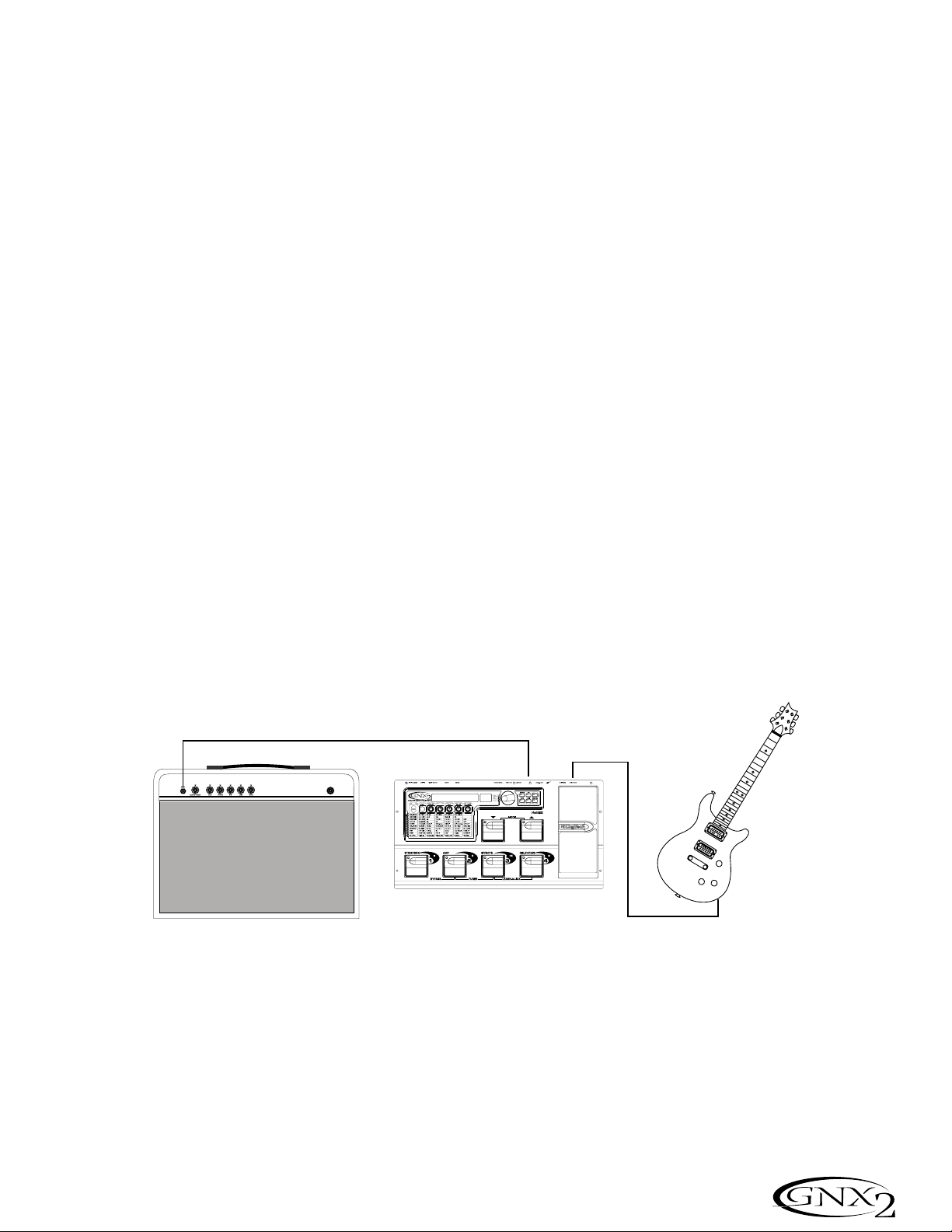
Mono Operation
1. Connect your guitar to the input of the GNX2.
2. Connect the GNX2’s left output to the instrument input on your amplifier, or
to the line input of a power amp.
3. Select Mono as the Output mode from the Utility menu. See page 40 for
more on selecting the Output mode.
Stereo Operation
1. Connect the guitar to the input of the GNX2.
2. Connect the GNX2’s Left output to the input of one amplifier or channel of a
power amp.
3. Connect the GNX2’s right output to a second amplifier, or to a second chan-
nel of a power amp.
4. Select Stereo as the Output mode from the Utility menu. See page 40 for
more on selecting the Output mode.
12. MIDI In
Este conector recibe todos los datos MIDI entrantes. Conecte esta entrada a la
toma MIDI out de un ordenador, secuenciador, controlador MIDI o unidad de
almacenamiento MIDI.
13. MIDI Out/Thru
Este conector envía los datos MIDI emitidos desde el GNX2. Conecte esta clavija a la toma MIDI In de un ordenador o unidad de grabación MIDI exterior.
Cuando esté activa, la función MIDI Thru de esta clavija emitir· la misma información que sea recibida en la toma MIDI In del GNX2.
14. Enganche anti-tirones
Se usa para fijar el cable de alimentación y evitar posibles desconexiones accidentales durante la ejecución.
Inicio
Conexiones
El GNX2 dispone de varias opciones de conexión posibles.Puede hacer una conexión
en mono a un amplificador o etapa de potencia, en stereo a dos amplificadores o una
etapa de potencia stereo,directo a una mesa de mezclas o usar una combinación de
estas conexiones.Antes de conectar el GNX2, asegúrese que tanto el GNX2 como su
amplificador estén apagados.Los diagramas siguientes le muestran algunos ejemplos.
NOTA: El tipo de sistema de amplificación con el que será usado el
GNX2 debe ser elegido en la Configuración de sistema de destino del
menú de utilidades.Vea la página 40 para más información acerca de
estos ajustes.
Funcionamiento Mono
1. Conecte su guitarra a la entrada del GNX2.
2. Conecte la salida izquierda del GNX2 a la entrada de instrumento de su
amplificador o a la entrada de línea de una etapa de potencia.
3. Elija Mono como modo de salida en el menú de utilidades.Vea la página 40
para más información acerca del modo de salida.
Funcionamiento Stereo
1. Conecte la guitarra a la entrada del GNX2.
2. Conecte la salida izquierda del GNX2 a la entrada de un amplificador o a un
canal de una etapa de potencia.
3. Conecte la salida derecha del GNX2 a un segundo amplificador o a un segundo canal de la etapa de potencia.
4. Elija Stereo como modo de salida en el menú de utilidades.Vea la página 40
para más información acerca de la selección del modo de salida.
7
Introduction / Introducción
Guitar Input/Effect Return
Entrada de guitarra/retorno de efectos
Left Output
Salida izquierda
Input
Entrada
Page 14
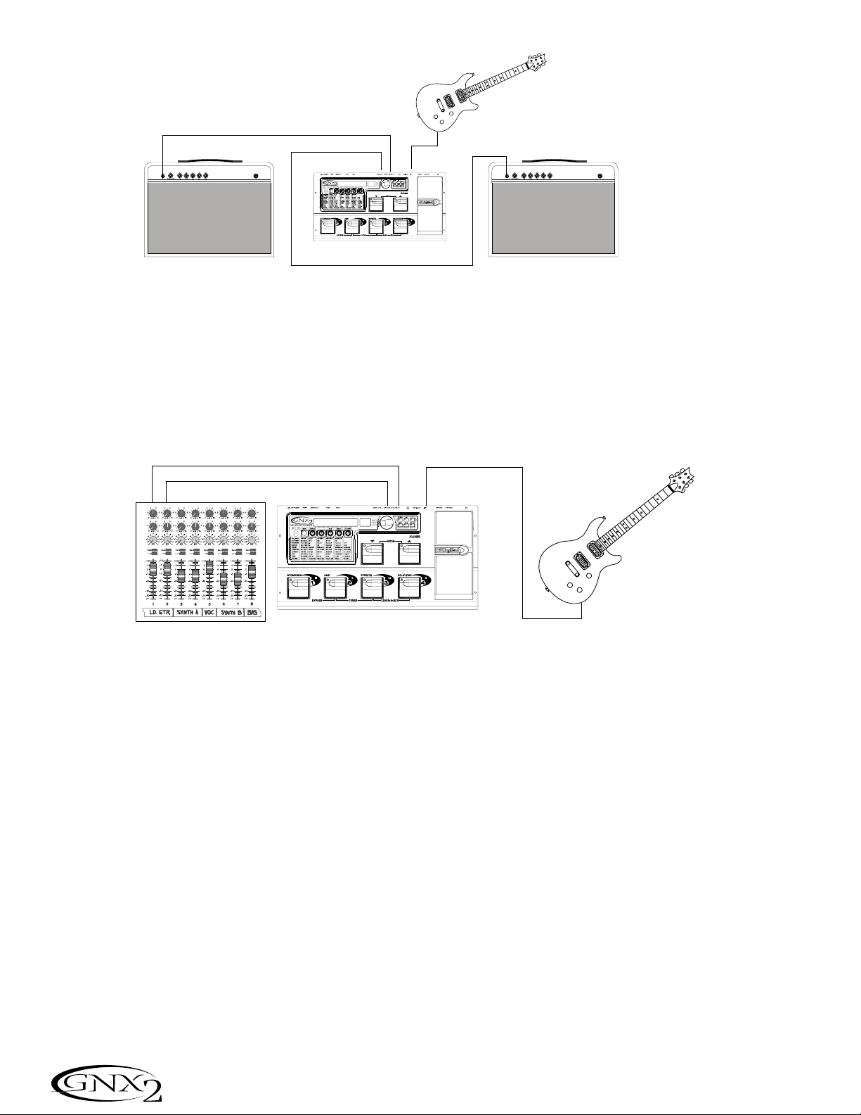
Direct to a Mixing Console
The GNX2 can be connected directly to the inputs of a house PA system, or a
recording console.
1. Connect the guitar to the GNX2’s input.
2. Connect the GNX2’s outputs to the channel inputs of the mixing console.
3. If the GNX2 is to be used in Stereo mode, set the pan controls of the mixer
hard left and right, and select Stereo as the output mode from the Utility menu.
See page 40 for more information on the Output mode.
S/PDIF Digital Output
The GNX2 includes a digital S/PDIF output that connects directly to the latest
digital recording devices and sound cards. Connect the GNX2’s S/PDIF output
to the S/PDIF input on your digital mixer or recorder. You must have S/PDIF
inputs on the receiving device in order to use this output. Be sure to use a 75
ohm or RCA video cable to connect from the Digital Output to a recording
device. You can use the analog and digital outputs of the GNX2 simultaneously.
NOTE: Do not connect the S/PDIF output to analog auxiliary, CD,
phono, or tape inputs on consumer electronic devices. It is not compatible with these inputs.
Applying Power
Once the audio connections are made, turn the GNX2’s Output Level on the
rear panel all the way down (counterclockwise). Connect the PSS3 to the
power jack on the back of the GNX2 and the other end to an AC outlet. Turn
the power switch On. Turn the power to your amplifier(s) on. Set the amp(s)
to a clean tone and set the tone controls to a flat EQ response (on most amps,
this would be 0 or 5 on the tone controls). Turn the Output Level of the
GNX2 up to increase the volume.
Directo a una mesa de mezclas
Puede conectar el GNX2 directamente a las entradas de un sistema PA, o a una
mesa de mezclas.
1. Conecte la guitarra a la entrada del GNX2.
2. Conecte después las salidas del GNX2 a los canales de entrada de la mesa de mezclas.
3. Si va a usar el GNX2 en el modo stereo, ajuste los controles de panorama de
la mesa de mezclas completamente a la izquierda y a la derecha y elija stereo
como modo de salida en el menú de utilidades del GNX2.Vea en la página 40
más información acerca de estos ajustes
Salida digital S/PDIF
El GNX2 incluye una salida digital S/PDIF para conectarlo directamente a los más moder-
nos sistema de grabación digital y tarjetas de sonido.Conecte la salida S/PDIF del GNX2 a
la entrada S/PDIF de su mesa de mezclas o grabadora digital. Para poder usar esta salida, su
unidad receptora deberá tener entradas S/PDIF.Asegúrese de usar un cable de vídeo RCA
o de 75 ohmios para realizar la conexión desde la salida digital a una unidad de grabación.
Puede usar simultáneamente las salidas digital y analógica del GNX2..
NOTA: No conecte la salida S/PDIF a entradas auxiliares, CD, phono o
de cinta de aparatos electrónicos. Las señales de esta salida no son
compatibles con esas entradas.
Encendido
Una vez que haya realizado las conexiones audio, baje a tope el nivel de salida
del panel trasero del GNX2 (a la izquierda). Conecte la fuente de alimentación
PSS3 a la entrada de corriente de la parte trasera del GNX2 y el otro extremo
a una salida de corriente alterna. Coloque el interruptor de encendido del
GNX2 en la posición On. Encienda después también su amplificador(s).Ajuste el
amplificador(s) a un sonido limpio y ajuste los controles de tono a una respuesta EQ plana (en la mayoría de amplificadores,esto suele estar sobre el 0 o el 5
en los controles de tono).Aumente el nivel de salida del GNX2 hasta conseguir
el nivel de volumen que quiera.
8
Introduction / Introducción
Guitar Input/Effect Return
Entrada de guitarra/retorno de efectos
Left Output
Salida izquierda
Right Output
Salida derecha
Left Output
Salida izquierda
Right Output
Salida derecha
Guitar Input/Effect Return
Input
Entrada
Entrada de guitarra/retorno de efectos
Input
Entrada
Page 15

About the GNX2
The Presets
A preset is a named and numbered location of a programmed sound that
resides in the GNX2. Presets can be recalled with the FOOTSWITCHES or
the DATA WHEEL. The GNX2 comes with 64 Factory and 64 User presets.
The Factory Presets do not let you store changes to them. The User presets let
you store changes. From the factory, the 64 User presets are exact duplicates
of the 64 Factory presets. This lets you make your own presets without
worrying about losing any of the original presets. When you select a preset, the
name of the preset appears in the green alpha-numeric display and the number
of the preset appears in the red numeric display. The User LED to the right of
the numeric display lights indicating the User preset is active. The Factory LED
lights indicating a Factory preset is active.
Performance Mode
When you first apply power to the GNX2,it powers up in Performance mode.
This is the mode used while you are performing. While in Performance mode,
the display shows the selected preset’s name and number. The vertical LEDs on
the Matrix indicate which effects are active for the selected preset. From
Performance mode, you have access to all of the GNX2’s presets.
Preset Mode
Preset Mode is the factory default operation mode when the GNX2 is first
powered up. In Preset mode, Footswitches 1-4 select presets in the current
bank. The Mode footswitches are used to select the 16 User Banks. Successive
presses of the MODE footswitches advances through all User/Factory Banks.
Pressing and holding a MODE footwitches scrolls through the User Banks.
Once a Bank has been selected, a preset within that bank needs to be selected.
If a preset is not selected within 5 seconds, the GNX2 returns to the previous
bank and preset.
FX Mode
FX Mode is another mode of operation that can be used during a performance.
The FX MODE button (located to the right of the Data Wheel) is used to
switch between Preset and FX Modes. When FX Mode is active, the FX
MODE button lights. In FX MODE, the 1-4 Footswitches turn on and off the
effects. Footswitch 1 turns the Distortion Stompbox modeling on and off.
Footswitch 2 switches between the Green,Red, and Yellow amp channels.
Footswitch 3 turns the Chorus/Mod Effects module on and off. Footswitch 3
turns the Delay on and off. Footswitch 4 turns the Delay on and off. The Mode
footswitches are used to navigate through all of the GNX2’s presets.
As an added feature, the Delay footswitch can be used as a tap-tempo switch for
setting the delay time during live performance. While the delay is on, press and
hold the Delay footswitch while in FX Mode to turn it into a tap-tempo delay
switch. Press and hold it again to change it back to a Delay on and off switch.
Acerca del GNX2
Los Presets
Los Presets son posiciones con nombres y números de sonidos programados que
residen en el GNX2. Los presets pueden ser cargados con los pedales de disparo o con
la rueda DATA. El GNX2 viene con 64 presets de fábrica y 64 de usuario. Los presets
de fábrica no le permiten almacenar datos sobre ellos.Los presets de usuario son
posiciones en las que puede almacenar sus creaciones. Cuando sale de fábrica, los
64 presets de usuario son réplicas exactas de los 64 presets de fábrica.Esto le permite
crear sus propios presets sin preocuparse de perder ninguno de los sonidos originales.
Cuando elige un Preset, en la pantalla alfanumérica aparecerá el nombre del mismo,
mientras que su número será visualizado en la pantalla numérica roja. El LED User que
está a la derecha de la pantalla numérica se ilumina para indicar si está activo un preset
de usuario. El piloto Factory se ilumina para indicar que está activo un preset de fábrica.
Modo de ejecución
Cuando encienda por primera vez el GNX2, se encenderá en el modo de ejecución.
Este es el modo usado mientras está tocando.Mientras esté en este modo, la pantalla le mostrará el nombre y el número del preset activo entonces. Los pilotos verticales de la matriz le indicarán los efectos que están activos en el preset elegido.
Desde el modo de ejecución, puede acceder a todos los presets del GNX2.
Modo de Preset
Este es el modo por defecto cuando la unidad sale de fábrica. En el modo de Preset,
los pedales de disparo 1-4 cargarán los Presets en el banco activo en ese momento.
Los pedales Mode se usan para elegir los 16 bancos de usuario / fábrica. Las pulsaciones sucesivas sobre los pedales MODE harán que vaya pasando por todos los
bancos de usuario/fábrica. Si mantiene pulsado uno de estos pedales MODE irá
pasando por los bancos de usuario. Una vez que haya elegido el banco que quiera,
deberá elegir un preset dentro de ese banco para activarlo. Si no elige ningún preset
en 5 segundos, el GNX2 volverá al último banco y preset que hubiese estado activo.
Modo FX
El modo FX es otro modo operativo que puede usar durante una ejecución. El
botón FX MODE (situado a la derecha de la rueda Data) se utiliza para cam-
biar entre los modos Preset y FX. Cuando el modo FX está activo, el piloto del
botón FX MODE se ilumina. En el modo FX,los pedales de disparo 1-4 activan
o desactivan los efectos. El pedal de disparo 1 activa o desactiva el modelado de
pedal de efecto de distorsión. El pedal 2 cambia entre los canales de amplificación verde, rojo y amarillo.El pedal 3 activa o desactiva el módulo de efectos
de modulación/chorus. El pedal 4 activa o desactiva el retardo.Los pedales de
disparo Mode se usan para ir pasando por los distintos presets del GNX2.
Como una función añadida, el pedal de disparo de retardo puede ser usado
como un interruptor de marcación de tempo para el ajuste del tiempo de retardo durante una actuación en directo. Mientras está activo el retardo, mantenga
pulsado este pedal de disparo de retardo mientras está en el modo FX para
convertirlo en un interruptor de marcación de tempo de retardo. Manténgalo
pulsado de nuevo para volverlo a convertir en un interruptor de activación o
desactivación del retardo.
9
Editing Functions / Funciones de edición
Preset Name
Nombre del preset
NAMES
Preset Number
Número del preset
64
LEDs Indicate Whether a User
or Factory Preset is Active
Estos pilotos indican si está activo
un preset de usuario o de fábrica
Page 16
The Footswitches
The GNX2 1-4 footswitches are primarily used to select presets or turn on and
off effects, depending on which mode is selected. However, these footswitches
are also used to access other GNX2 functions. For example, pressing
Footswitches 1 and 2 simultaneously, or pressing the lit Footswitch (in Preset
mode) bypasses the the current preset. Pressing Footswitches 2 and 3 simultaneously accesses the Tuner mode. Pressing Footswitches 3 and 4 simultaneously
activates the Learn-A-Lick mode. In Learn-A-Lick mode, Footswitches 1-4 control various Learn-A-Lick functions.
The Expression Pedal
As you go through the different presets in the GNX2, you will find that the
expression pedal has different functions.The Expression Pedal can control three
different parameters in each Preset. Rock the Expression Pedal back and forth
to change the values of the assigned parameters. The pedal can control
assigned minimum and maximum values (stop points) for each parameter. The
Expression Pedal also includes a feature called V-Switch that allows you to override the Parameters assigned to the Expression Pedal and replace them with the
Wah effect. See page 37 for more information on assigning the Expression
Pedal.
Bypass Mode
The GNX2 presets can be bypassed for a clean, unprocessed guitar tone.
Bypass mode turns off all effects and modeling. To bypass the GNX2 in Preset
mode, press the active preset’s Footswitch (the 1-4 footswitch that is lit), or
press Footswitches 1 and 2 simultaneously. To bypass the GNX2 while in FX
Mode, press Footswitches 1 and 2 simultaneously. When the GNX2 is bypassed,
the display reads
BYPASS
and all LEDs in the matrix are off. Press any
Footswitch to exit Bypass and return to the last preset. The Matrix and
Programming buttons are not available in Bypass mode.
Tuner Mode
The Tuner in the GNX2 lets you quickly tune or check the tuning on your guitar. Press Footswitches 2 and 3 simultaneously to enter Tuner mode. The display briefly flashes
TUNER
. To begin tuning,play a note on your guitar (a harmonic at the 12th fret usually works best).The red numeric display shows the
note being played, and the green alpha-numeric display indicates whether the
note is sharp or flat. Arrows to the left (
<<<
) indicate the note is sharp and
should be tuned down. Arrows to the right (
>>>
) indicate the note is flat and
should be tuned up. When your note is in tune,
-><-
is displayed.
In Tuner mode, you can set your tuning reference with the Data Wheel. The
default factory setting is A=440 Hz. The tuning references range from 427Hz to
453Hz (± 50 cents (1/2 semitone) from either direction of 440Hz). Below
427Hz, are alternate dropped tunings. The alternate tunings are
REF A
b
(A=Ab),
REF G
(A=G), and
REF G
b (A=Gb). The display window briefly
flashes the selected tuning preference.
Exit tuner mode by pressing any of the Footswitches.
Jam-A-Long
The Jam-A-Long feature lets you connect a Tape, CD, or MP3 player to the
GNX2. The tape, CD,or MP3 player’s signal is output through the GNX2’s left,
right, and headphone outputs. To use the Jam-A-Long feature, connect the headphone output of your player to the JAM-A-LONG INPUT on the rear panel
of the GNX2. Use a 1/8” stereo cable, and press play on your Tape, CD, or MP3
player.
Los pedales de disparo
Los pedales de disparo 1-4 del GNX2 se usan principalmente para elegir los presets
o activar y desactivar efectos, dependiendo del modo elegido.Sin embargo, estos pedales de disparo se usan también para acceder a otras funciones en el GNX2.Por
ejemplo, si pulsa simultáneamente los pedales de disparo 1 y 2, o si pulsa el pedal de
disparo iluminado en ese momento (en el modo Preset),anulará o dejará en bypass
el preset activo.El mantener pulsados simultáneamente los pedales de disparo 2 y 3
le dará acceso al modo de afinador. El pulsar simultáneamente los pedales de disparo
3 y 4 activar· el modo Learn-A-Lick. En este modo, los cuatro pedales controlarán las
distintas funciones del Learn-A-Lick.
El pedal de expresión
Según vaya pasando por los distintos Presets del GNX2, observará que el pedal de
expresión tiene distintas funciones.Puede asignar este pedal para controlar tres
parámetros distintos en cada Preset.El girar el pedal de expresión adelante y atrás
hará que cambie el valor de los parámetros asignados.El pedal puede controlar valores mÌnimos y máximos (puntos de parada) asignados para cada parámetro. El pedal
de expresión también incluye una función llamada V-Switch que le permite anular los
parámetros asignados al pedal de expresión y sustituir esa asignación por el Wah.Vea
en la página 37 más información acerca de la asignación del pedal de expresión.
Modo de anulación o bypass
Los presets del GNX2 pueden ser anulados para conseguir un sonido de guitarra limpio,
directo y sin procesado.Este modo bypass desactiva todos los efectos y el modelado. Para
anular el GNX2 en el modo de Preset,pulse el pedal de disparo que represente al Preset
activo (el pedal de disparo 1-4 que esté iluminado), o pulse simultáneamente el pedal de
disparo 1 y 2.Para anular el GNX2 mientras esté en el modo FX, pulse simultáneamente
los pedales de disparo 1 y 2.Cuando el GNX2 está en bypass, la pantalla le indicará
BYPASS
y todos los pilotos de la matriz se apagarán.Pulse cualquiera de los pedales de
disparo para salir de esta anulación y volver al último preset usado.En el modo de anulación no puede usar ninguno de los botones de la matriz o de programación.
Modo de afinador
El afinador del GNX2 le permite rápidamente afinar o comprobar la afinación
de su guitarra. Pulse simultáneamente los pedales de disparo 2 y 3 para acceder
al modo de afinador. En la pantalla aparecerá brevemente
TUNER
. Para comenzar la afinación, toque una nota en su guitarra (un armónico en el 12avo traste
suele funcionar bien). La pantalla roja numérica le mostrará la nota que esté
tocando, y la pantalla alfanumérica verde le indicará si la nota está bemolada o
sostenida. Las flechas a la izquierda (
<<<
) le indican que la nota está sostenida y
que debería disminuir su tono. Las flechas a la derecha (
>>>
) indican que el
tono está bemolado y que debería aumentarlo. Cuando la nota esté en su tono
perfecto, en pantalla aparecer·
-><-
.
En el modo de afinador, puede elegir su referencia de afinación con la rueda Data. El
valor de fábrica por defecto es A=440Hz. El rango de referencias de afinación va desde
los 427Hz a los 453Hz ( ± 50 centésimas (1/2 semitono) en ambas direcciones del
440Hz). Por debajo de los 427Hz,también encontrará algunas afinaciones inferiores.
Estas afinaciones alternativas son
REF A
b (A=Ab),
REF G
(A=G) y
REF G
b
(A=Gb). En la pantalla parpadeará brevemente la referencia de afinación elegida.
Para salir del modo de afinador no tiene más que pulsar cualquiera de los pedales de disparo.
Jam-A-Long
La función Jam-A-Long le permite conectar un reproductor de cinta, CD o MP3
al GNX2. La señal de su reproductor de CD, MP3 o cinta es emitida a través de
las salidas izquierda, derecha y de auriculares del GNX2. Para usar la función
Jam-A-Long, conecte la salida de auriculares de su unidad reproductora a la
Entrada JAM-A-LONG del panel trasero del GNX2. Use un cable stereo de
3,5mm. y pulse Play en su reproductor.
10
Editing Functions / Funciones de edición
Page 17

Learn-A-Lick Mode
The Learn-A-Lick function allows you to record a 9 second passage of music
and play it back as slowly as 1/4 the original speed with no change in pitch. This
is very useful for picking out the notes of a fast guitar solo.
There are 6 Learn-A-Lick functions.They are:
• Stop (Controlled by Footswitch 1)
• Play (Controlled by Footswitch 2)
• Rewind (Controlled by Footswitch 3)
• Record (Controlled by Footswitch 4)
• Tempo Down (Controlled by rotating the Data Wheel counter-clockwise)
• Tempo Up (Controlled by rotating the Data Wheel clockwise)
Using Learn-A-Lick
1. Connect the player’s headphone output to the Jam-A-Long input jack on the
rear panel using a 1/8” stereo plug. Set the volume level of the player.
2. Find the passage you want to record and pause the Tape, CD, or MP3 player.
3. Press and hold the number 2 and 3 Footswitches to enter Learn-A-Lick
mode.The display reads:
Lrn LICK
4. Release the pause button on your playback device and press the number 4
Footswitch. The display reads:
RECORD
. The red numeric display provides
a time elapsed reference while recording is in process. When recording is
complete, the recorded passage is set in an auto-loop playback mode indicated by
play
appearing in the display.
5. Press Stop or Pause on the playback device.
6. Rotate the DATA WHEEL counterclockwise to slow the playback down, or
clockwise to increase the playback speed at 1/8 speed intervals.Your interval
choices include:
FULL,7/8,3/4,5/8,1/2,3/8,and 1/4
speeds.
7. Press Footswitch 3 to step back through the loop at 1 second intervals.
8.The EXPRESSION PEDAL controls the output level of the recorded
phrase.
9.To stop the playback, press Footswitch 1.
10.To resume playback, press Footswitch 2.
11.To record a new passage, press Footswitch 4.
12.To exit the Learn-A-Lick mode, press and hold Footswitches 3 and 4, or
press EXIT.
Rhythm Trainer
The Rhythm Trainer in the GNX2 is a tool that can be used to develop a great
sense of timing, rehearse different musical styles,or just to jam with. The
Rhythm Trainer plays sampled drum patterns in an infinite loop. You can select
from a variety of patterns, change the tempo, and adjust the playback level while
using the Rhythm Trainer. When the Rhythm Trainer is enabled,the drum patterns are mixed with your guitar signal at the GNX2’s left, right, and headphone
outputs.
To activate the Rhythm Trainer, follow these steps:
1. Press the RHYTHM button.The Rhythm button’s LED lights and the current
drum pattern will begin playing. If Rhythm mode is enabled from Performance
mode, the Store, Utility, and Amp Save LEDs light.
2. Press the Store, Utility, or Amp Save buttons to adjust the Pattern,Tempo, or
Level using the DATA WHEEL.
Modo Learn-A-Lick
La función Learn-A-Lick le permite grabar un pasaje de hasta 9 segundos de
música y reproducirla hasta a 1/4 de la velocidad normal sin cambio en el tono.
Esto resulta muy útil para hacer un dictado musical de las notas que forman un
solo rápido de guitarra.
Este modo dispone de 6 funciones, que son:
• Stop (Controlado por el pedal de disparo número 1)
• Reproducción (Controlado por el pedal de disparo número 2)
• Rebobinado (Controlado por el pedal de disparo número 3)
• Grabación (Controlado por el pedal de disparo número 4)
• Tempo abajo (Controlado por el giro hacia la izquierda de la rueda Data)
• Tempo arriba (Controlado por el giro a la derecha de la rueda Data)
Uso del Learn-A-Lick
1. Conecte la salida de auriculares de su reproductor de cinta,CD o MP3 a la
toma de entrada Jam-A-Long del panel trasero usando un conector stereo de
3,5mm.Ajuste el nivel de volumen en el reproductor.
2. Localice el pasaje que quiera grabar y pulse la pausa en el reproductor de
cinta, CD o MP3
3. Mantenga pulsados los pedales de disparo 2 y 3 para acceder al modo LearnA-Lick. En la pantalla aparecer·:
Lrn LICK
4. Deje de pulsar el botón de pausa en su unidad reproductora y pulse el pedal
de disparo 4 (grabación). En la pantalla aparecer·:
RECORD
. La pantalla
numérica roja le irá dando una indicación del tiempo transcurrido mientras se
realiza la grabación. Cuando la grabación haya sido completada,la frase musical quedará ajustada en un modo de reproducción de bucle automático indicado por el mensaje
play
en la pantalla.
5. Pulse la parada o la pausa en la unidad reproductora.
6. Gire a la izquierda la rueda Data para ralentizar la reproducción o a la
derecha para aumentar la velocidad de reproducción hasta la normal a intervalos de 1/8 de velocidad. Sus opciones posibles son:
FULL,7/8,3/4
,
5/8,1/2,3/8,y1/4
.
7. Pulse el pedal de disparo 3 para desplazarse hacia atrás por el bucle en intervalos de 1 segundo.
8. El Pedal de expresión controlará el nivel de salida de la frase musical grabada.
9. Para detener la reproducción, pulse el pedal de disparo 1.
10. Para reiniciar la reproducción,pulse de nuevo el pedal de disparo 2.
11. Para grabar un nuevo pasaje, pulse el pedal de disparo 4.
12. Para salir del modo Learn-A-Lick, mantenga pulsados los pedales de disparo
3 y 4, o pulse el botón EXIT.
Entrenador rítmico
El entrenador rítmico del GNX2 es una herramienta que puede usar para desarrollar un buen sentido del ritmo y la temporización, ensayar con distintos estilos musicales o simplemente para improvisar. Esta función reproduce ritmos de batería
muestreados en un bucle infinito,permitiéndole elegir entre una amplia variedad de
patrones, cambiar el tempo y ajustar el nivel de volumen mientras lo usa. Cuando el
entrenador rítmico está activado, los muestreos de batería son mezclados con su
señal de guitarra en las salidas izquierda, derecha y de auriculares del GNX2.
Para activar el entrenador rítmico, siga estos pasos:
1. Pulse el botón RHYTHM El piloto de este botón se iluminará y el patrón rítmi-
co activo en ese momento comenzará a reproducirse.Si activa el modo rítmico
desde el modo de ejecución, los pilotos de los botones Store, Utility y Amp Save.
2. Pulse los botones Store, Utility o Amp Save para ajustar el patrón, tempo o
nivel usando la rueda DATA.
11
Editing Functions / Funciones de edición
Page 18

Pattern
Press the STORE (Pattern) button to adjust the drum pattern. The selected
drum pattern is shown in the display. Use the DATA WHEEL to select a new
pattern. There are 30 different Patterns and a metronome available including:
Tempo
Press the UTILITY (Tempo) button to adjust the tempo. The display shows
the current tempo in beats per minute (BPM). Use the DATA WHEEL to
select a new tempo. Tempo ranges from 40 beats per minute (
40BPM
) to 240
beats per minute (
240BPM
).
Level
Press the AMP SAVE (Level) button to adjust the level. The display reads
DruM LVL
(drum level). Use the DATA WHEEL to select the playback vol-
ume of the drum loop. Level ranges from 1 to 99.
3. Press the RHYTHM button again to turn the Rhythm Trainer off.
Patrón
Pulse el botón STORE (Pattern) para ajustar el patrón de batería. El patrón activo en ese momento aparecerá en la pantalla. Use la rueda DATA para elegir un
nuevo patrón. Dispone de 30 patrones distintos y un metrónomo entre los que
elegir:
Tempo
Pulse el botón UTILITY (Tempo) para ajustar el tempo. En pantalla aparecerá
el tempo activo en tiempos por minuto (BPM). Use la rueda DATA para ajustar
un nuevo tempo.El rango del tempo va desde los 40 tiempos por minuto
(
40BPM
) a los 240 tiempos por minuto (
240BPM
).
Nivel
Pulse el botón AMP SAVE (Level) para ajustar el nivel. En pantalla aparecerá
DruM LVL
(nivel de baterÌa). Use la rueda DATA para elegir el volumen de
reproducción del bucle de batería. El rango del nivel va desde 1 a 99.
3. Pulse de nuevo el botón RHYTHM para desactivar el entrenador rítmico.
ROCK 1
ROCK 2
ROCK 3
ROCK 4
HrdROCK1
HrdROCK2
HrdROCK3
POP 1
POP 2
POP 3
FUNK 1
FUNK 2
FUNK 3
BLUES
JAZZ
DANCE 1
DANCE 2
DANCE 3
DANCE 4
URBAN 1
URBAN 2
CouNTRY1
CouNTRY2
CouNTRY3
SWING 1
SWING 2
REGGAE
CHACHA
BOSSA 1
BOSSA 2
METROnom
12
Editing Functions / Funciones de edición
Page 19

Editing Functions
Editing/Creating a Preset
The GNX2 was designed to make the process of sound creation easy and intuitive. Because the GNX2 provides both Amp Modeling and Effects Processing,
the editing functions have been divided into two sections:the Amp/Cabinet
Modeling section and the Effects section. The GeNetX™ technology contained
in the GNX2 allows you to go much further than mere Amp Modeling.
GeNetX™ lets you create your own Amp/Cabinet HyperModel™ and store
this custom creation to a User Amp/Cabinet location. When editing either the
Amp/Cabinet Modeling, or the Effects section, you must start with one of the
User or Factory Presets. It is not possible to start with a completely empty
preset. The preset you begin with does not need to be in the location that you
intend to save it. To begin creating a HyperModel™ or just edit the effects, you
must select a preset as your starting point.
Amp/Cabinet Modeling
Once you have selected a preset, you can select the Amp Models or Cabinet
Types for your preset.Amp/Cabinet Modeling is a technology that applies the
tone of one of several vintage or modern Amp Models and Cabinet Types to
your guitar signal. The GNX2 includes accurate emulations of 15 popular Amp
Models, 1 Acoustic Guitar Simulation, and 12 Speaker Cabinet Types.Your choices include:
Amp Models
Marshall® is a registered trademark of Marshall Amplification Plc. Vox® is a registered trademark of Korg UK. Fender, Matchless, HiWatt,and Mesa Boogie, are trademarks of their respective companies and are in no way associated with DigiTech.
Cabinet Types
Editing Amp Models and Cabinet Types
Each GNX2 preset has a Green, Red, and Yellow (Warped) Amp Channel. The
Green and Red Amp Channels include individually selectable Amp Models,
Cabinet Types, Gain, EQ, and Level settings.The Speaker Cabinet can also be
tuned meaning that you can select the Cabinet’s resonant frequency.Once the
Models have been selected for the Green and Red channels, the channels can be
toggled instantly using the Amp Channel Footswitch (only when FX Mode is
active).Then the characteristics of the two Models selected for the Green and
Red channels can be Warped together resulting in a completely new
HyperModel™.
Funciones de edición
Edición/Creación de un Preset
El GNX2 ha sido diseñado para hacer que el proceso de creación sonora sea fácil e
intuitivo.Dado que el GNX2 le ofrece tanto modelado de amplificador como procesado de efectos, las funciones de edición han sido divididas en dos secciones;la sección de modelado de amplificador/recinto y la sección de efectos.La tecnología
GeNetX™ que hay dentro del GNX2 le permite ir mucho más allá que el “simple”
modelado de amplificador. El GeNetX™ le permite crear su propio HyperModel™
de amplificador/recinto y almacenar esa creación propia en una posición de amplificador/recinto de usuario.Cuando esté editando tanto la sección de modelado de
amplificador/recinto,como la de efectos, debe comenzar con uno de los presets de
fábrica o de usuario.No es posible comenzar con un preset completamente vacío. El
Preset con el que empiece no tiene por qué estar necesariamente en la posición en
la que piense dejar el nuevo.Para comenzar la creación de un HyperModel™ o simplemente la edición de los efectos, tiene que elegir un preset como punto de partida.
Modelado de amplificador/recinto
Una vez que haya elegido el preset que quiera editar, puede elegir los modelos de
amplificador o tipos de recinto para su preset. El modelado de amplificador / recinto
es una tecnología que aplica el sonido de algunos de los mejores amplificadores de
guitarra clásicos y modernos y tipos de recintos a su señal de guitarra. El GNX2
incluye perfectas simulaciones de 15 populares modelos de amplificador, 1 simulación
de guitarra acústica y 12 tipos de recintos acústicos.Sus opciones incluyen:
Modelos de amplificador
Marshall® es una marca registrada de Marshall Amplification Plc.Vox® es una marca registrada de Korg UK.Fender,Matchless, HiWatt y Mesa Boogie son marcas registradas de
sus respectivas compañÌas y no están asociadas en forma alguna con DigiTech.
Cabinet Types
Edición de modelos de amplificador y recintos
Cada preset del GNX2 tiene un canal de amplificación verde, rojo y amarillo
(enlazado). Los canales verde y rojo incluyen modelos de amplificador, tipos de
recinto, ganancia, EQ y ajustes de nivel asignables de forma individual.También
puede afinar el recinto acústico, lo que implica que puede elegir la frecuencia
resonante de la caja. Una vez que haya ajustado estos parámetros para los
canales verde y rojo, puede cambiar inmediatamente entre ellos usando el pedal
de disparo de canal de amplificación (solo cuando está activo el modo FX).
Después puede enlazar juntas las características de modelo de los dos modelos
para los canales verde y rojo para dar como resultado un HyperModel™ completamente nuevo.
direct 1
- Turns the cabinet modeling off
AMer2X12
2 - American 2x12
BRit4X12
3 - British 4x12
vntg4x12
4 - Vintage 30 4x12
BRit2X12
5 - British 2x12
AMer1X12
6 - American 1x12
BLnd2X12
7 - Blonde 2x12
Fane4X12
8 - Fane 4x12
GRnb4X12
9 - Greenback 4x12
botq4X12
10 - Boutique 4x12
amer4x10
11 - Bassman 4x10
65 1x12
12 - ‘65 Tweed 1x12
Jazz1x15
13 - Pro 1x15
EMPTY
U1 to U9 - User Locations
direct 1
- Desactiva el modelado de recintos
AMer2X12
2 - American 2x12
BRit4X12
3 - British 4x12
vntg4x12
4 - Vintage 30 4x12
BRit2X12
5 - British 2x12
AMer1X12
6 - American 1x12
BLnd2X12
7 - Blonde 2x12
Fane4X12
8 - Fane 4x12
GRnb4X12
9 - Greenback 4x12
botq4X12
10 - Boutique 4x12
amer4x10
11 - Bassman 4x10
65 1x12
12 - Tweed 1x12 del año 65
Jazz1x15
13 - Pro 1x15
EMPTY
U1 to U9 - Posiciones de usuario
DIRECT
1 - Turns the amp modeling off
BLacKFAC
2 - Based on a ‘65 Fender Twin Reverb
BOUTIQue
3 - Based on a Matchless DC30
RECTfied
4 - Based on a Mesa Dual Rectifier
HOTROD
5 - Based on a Mesa Boogie Mark II C
tweeD
6 - Based on a ‘57 Fender Tweed Deluxe
BRiTCMBo
7 - Based on a Vox AC30 top boost
CLeaNTUB
8 - A clean tube combo setting
BRiTSTcK
9 - Based on a ‘78 Marshall Master Volume
CRUNCH
10 - A nice crunchy tube amp combo
HI GAIN
11 - A high gain tube amp
BLUES
12 - A sweet blues tone
MdrnGAiN
13 - Based on a Marshall JCM900
FUZZ
14 - A vintage fuzz distortion
BASS MaN
15 - Based on a Fender Bassman
HIWATtaG
16- Based on a HiWatt 50 watt stack
ACOUSTic
17 - A flat top acoustic guitar
EMPTY
U1 to U9 - User HyperModel™ Locations
DIRECT
1 - Desactiva el modelador de amplificador
BLacKFAC
2 - Basado en un Fender Twin Reverb del 65
BOUTIQue
3 - Basado en un Matchless DC30
RECTfied
4 - Basado en un Mesa Dual Rectifier
HOTROD
5 - Basado en un Mesa Boogie Mark II C
tweeD
6 - Basado en un Fender Tweed Deluxe del 57
BRiTCMBo
7 - Basado en un Vox AC30 top boost
CLeaNTUB
8 - Un combo a válvulas limpio
BRiTSTcK
9 - Basado en un Marshall Master Volume del 78
CRUNCH
10 - Un combo de tipo a válvulas con sonido
crujiente
HI GAIN
11 - amplificador a válvulas con alta ganancia
BLUES
12 - dulce sonido de blues
MdrnGAiN
13 - Basado en un Marshall JCM900
FUZZ
14 - Tradicional distorsión fuzz
BASS MaN
15 - Basado en un Fender Bassman
HIWATtaG
16- Basado en un HiWatt de tipo torre de
50 watios
ACOUSTic
17 - Guitarra acústica
EMPTY
U1 a U9 - Posiciones HyperModel™ de
usuario
13
Editing Functions / Funciones de edición
Page 20

Selecting Amp/Cabinet Models
The first step to editing an Amp Model, Cabinet Type, or creating your own
HyperModel™ is to select the Amp and Cabinet types for the Green and Red
Amp channels in your preset. To do this, the GNX2 must be in the Performance
mode, indicated by the Status button’s LED lighting yellow. EXIT returns you to
Performance mode regardless of the selected mode. The procedure for selecting an Amp Model or Cabinet Type for the Green or Red Amp Channels is as
follows:
1. Use the Parameter 1 knob (far left) to select the Green Amp Model. The Amp
Model name appears in the alpha-numeric display. See the Amp/Cabinet
Modeling section on page 13 for a complete list of Amp Models.
2. Use the Parameter 2 knob (second from the left) to select the Green Cabinet
Type. See the Amp/Cabinet Modeling section on page 13 for a complete list of
Cabinet Types.
3. Use the Parameter 4 knob (second from the right) to select the Red Amp
Model.
4. Use the Parameter 5 knob (far right) to select the Red Cabinet type.
Adjusting Amp Parameters
The Gain, EQ, and Level Parameters can be adjusted individually for the Green
and Red Amp Channels.The Gain ranges from 0 (
0
) to 99 (99).The Bass, Mid,
and Treble EQ range from -12 (
-12
dB) to 12 (
+12
dB).The Level ranges from 0
(
0
) to 99 (99).The procedure for adjusting the Amp Parameters is as follows:
1. Press the STATUS button until all horizontal LEDs across the columns light
green.This indicates that you have accessed the Amp Parameters for the
Green Channel.
2. Use the Parameter 1 knob to adjust the Gain (distortion drive) for the Green
Amp Channel.
3. Use the Parameter 2 knob to adjust the Bass (low frequency) enhancement
for the Green Amp Channel.
4. Use the Parameter 3 knob to adjust the Mid range frequency enhancement for
the Green Amp Channel.
5. Rotate the Parameter 4 knob to adjust the Treble (high frequency) enhancement for the Green Amp Channel.
6. Rotate the Parameter 5 knob to adjust the Level (volume) for the Green Amp
Channel.
7. Press the STATUS button again until all horizontal LEDs across the columns
turn red indicating the Amp Parameters for the Red Channel have been
accessed.Then repeat steps 2 through 6 for adjusting the Red Amp Channel.
Cabinet Tuning
The resonant frequency of the selected speaker cabinets can be tuned individu-
ally. Cabinet Tuning ranges from
-1™0
(one octave below) to
1™0
(one
octave above). The procedure for tuning the cabinets is as follows:
1. Press and hold the STATUS button. Release the Status button after about 2
seconds when the display reads Cabinet Tuning (
CAB TUNe
) and only the
LEDs next to the Parameter 2 and 5 knobs are lit.
2. Rotate the Parameter 2 knob to adjust the tuning of the Green Cabinet type
(
GT
).
3. Rotate the Parameter 5 knob to adjust the tuning of the Red Cabinet type
(
RT
).
4. Once the tuning has been selected for both Green and Red Cabinets, press
EXIT.
Selección de modelos de
amplificador/recinto acústico
El primer paso en la edición del modelo de amplificador, recinto acústico, o para la
creación de su propio HyperModel™ es elegir los tipos de amplificador y recinto
para los canales verde y rojo de su Preset.Para hacer esto, el GNX2 debe estar en el
modo de ejecución que es indicado por el LED del botón Status iluminado en amarillo. El pulsar el botón EXIT devolverá el GNX2 al modo de ejecución sin tener en
cuenta el modo en el que esté en ese momento.El proceso para elegir un modelo de
amplificador o tipo de recinto para los canales verde y rojo es el siguiente:
1. Use el mando Parameter 1 (tope izquierda) para elegir el modelo de amplificador verde. El nombre del modelo de amplificador aparecerá en la pantalla
alfanumérica.Vea la sección de modelado de amplificador/recinto en la
página 13 si quiere ver un listado completo de los modelos.
2. Use el mando Parameter 2 (segundo por la izquierda) para elegir el tipo de
recinto verde.Vea la sección de modelado de amplificador/recinto en la
página 13 si quiere ver un listado completo de los tipos de recinto.
3. Use el mando Parameter 4 (segundo por la derecha) para elegir el modelo de
amplificador del canal rojo.
4. Use el mando Parameter 5 (tope derecha) para elegir el tipo de recinto del
canal rojo.
Ajuste de los parámetros de amplificador
En los canales de amplificación verde y rojo puede ajustar de forma individual los parámet-
ros de ganancia,EQ y nivel. El rango de ganancia va desde 0 (
0
) a 99 (99). El rango de EQ
de agudos, medios y graves de -12 (
-12
dB) a 12 (
+12
dB). El nivel cubre un rango de 0
(
0
) a 99 (99). El proceso para el ajuste de estos parámetros es el siguiente:
1. Pulse el botón Status hasta que todos los LEDs horizontales de las columnas
se iluminen en verde. Esto indica que ha accedido a los parámetros de amplificación del canal verde.
2. Use el mando Parameter 1 para ajustar la ganancia (saturación) para el canal
de amplificación verde.
3. Use el mando Parameter 2 para ajustar el realce de graves (bajas frecuencias)
para el canal de amplificación verde.
4. Use el mando Parameter 3 para ajustar el realce de las frecuencias de rango
medio para el canal verde.
5. Use el mando Parameter 4 para ajustar el realce de agudos (altas frecuencias)
del canal verde.
6. Gire el mando Parameter 5 para ajustar el nivel (volumen) del canal de amplificación verde.
7. Pulse de nuevo el botón Status hasta que todos los LEDs horizontales en las
columnas se iluminen en rojo para indicar que ha accedido a los parámetros de
amplificación del canal rojo.Repita luego los pasos 2 a 6 para ajustar el canal rojo.
Afinación del recinto acústico
También puede afinar de forma individual la frecuencia resonante del recinto acústico elegido. Los rangos de afinación de recinto van desde
-1™0
(una octava abajo)
a
1™0
(una octava arriba). El proceso para afinar los recintos es el siguiente:
1. Mantenga pulsado el botón STATUS.Deje de pulsarlo tras unos 2 segundos
cuando en la pantalla aparezca
CAB TUNe
(afinación de recinto) y sólo
estén iluminados los LEDs que están al lado de los mandos Parameter 2 y 5.
2. Gire el mando Parameter 2 para ajustar la afinación del tipo de recinto del
canal verde (
GT
).
3. Gire el mando Parameter 5 para ajustar la afinación del tipo de recinto del
canal rojo (
RT
).
4. Una vez que haya elegido la afinación que quiera para ambos tipos de recin-
tos, pulse EXIT.
14
Editing Functions / Funciones de edición
Page 21

Creating HyperModels™
Creating new, unique HyperModels™ is what GeNetX™ is all about. Once the
Green and Red Amp Models and Cabinet types are selected, and the Amp
Parameters and Cabinet Tuning have been adjusted, GeNetX™ technology lets
you do something amazing. The characteristics of each Amp and Cabinet
assigned to the Green and Red Channels can actually be combined or “Warped”
to create a completely new Amp HyperModel™. The procedure for Warping
the Green and Red Amps together is as follows:
1. Press the Status button until its LED lights yellow.
2. Rotate the Parameter 3 knob to Warp the Green and Red Amps and Cabinets
together. Rotating counterclockwise adds more of the Green Channel characteristics, and clockwise adds more of the Red Channel characteristics.
Saving HyperModels™ (Amp Save)
When you have finished editing the Green and Red Channels, you
must save the HyperModel™ for future use. This HyperModel™ can
be saved in one of 9 User HyperModel™ locations. After it has been
saved, it can be used in either the Green or Red Amp Channel. The
Amp Save procedure is as follows:
1. Press the AMP SAVE button. The Amp Save button begins flash-
ing and the display reads
NEWAMP
. The Nof
NEWAMP
is flashing
indicating that you can name your HyperModel™.
2. Use the DATA WHEEL to select the alpha-numeric character.
3. Use the RHYTHM button to move to the next character (to the
right), or the FX MODE button to select the previous character
(to the left).
4. Repeat steps 2 and 3 until the HyperModel™ name appears in the
display.
5. Press the AMP SAVE button again to select one of the 9 User
HyperModel™ locations. If the GNX2 has any unused
HyperModel™ locations available, the display reads
EMPTY U1
.
The U1 flashes indicating that this is the first available location for
HyperModel to be stored. If all 9 HyperModel™ locations are full,
the GNX2 defaults to the first HyperModel™ location and displays the name of HyperModel™ stored in the number 1 location.
6. Use the DATA WHEEL to select a User location to save the
HyperModel. If all locations have been used, the display shows the
name of the HyperModel™ about to be overwritten.
7. Press the AMP SAVE button again to complete the Amp Save
procedure.
Press Exit at any time during the Amp Save procedure to abort the
process.
Note:The Amp Save procedure only saves Amp/Cabinet combinations
to the User HyperModel™ locations. It does not store changes or the
new HyperModel™ to the selected preset. See page 16 for information on storing changes to a Preset
Editing the Effects
The GNX2 contains a comprehensive library of fully programmable, studio quality Effects. The Effects section is accessed with the Effect Select Up/Down buttons.The Matrix LEDs light one at a time to identify the selected row of effects
. When you have selected the effect row, you have up to 5 Parameters that can
be edited. Each effect row is divided into 6 columns of Parameters.The first
column is the on/off control. Pressing the Status button at the top of the first
column turns the effect group on and off. The knobs at the top of the other 5
columns control the Parameters listed directly beneath the corresponding knob.
Each effect’s parameter is labeled in the Matrix. When a knob is turned, the
corresponding parameter name appears in the green alpha-numeric display and
the parameter value displays in the red numeric display.
Creación del HyperModels™
La creación de nuevos y únicos HyperModels™ es el verdadero fin del
GeNetX™. Una vez que haya elegido los tipos de amplificador y recinto para
los canales verde y rojo y haya ajustado los parámetros de estos modelos, la
tecnología GeNetX™ le permite hacer algo maravilloso.Las características de
cada amplificador y recinto asignados a los canales verde y rojo pueden ser
combinados o “enlazados” para crear un HyperModel™ completamente nuevo.
El proceso para ese enlace de los canales verde y rojo juntos es el siguiente:
1. Pulse el botón Status hasta que su LED esté iluminado en amarillo.
2. Gire el mando Parameter 3 para mezclar juntos los amplificadores y recintos verde
y rojo.El giro de este mando hacia la izquierda añadirá más características del canal
verde, mientras que el giro a la derecha añadirá más características del canal rojo.
Almacenamiento de HyperModels™
(Amp Save)
Cuando haya terminado de editar los canales verde y rojo, deberá almacenar
el HyperModel™ para poder usarlo en el futuro. Este HyperModel™ puede
ser almacenado en una de las 9 posiciones de HyperModel™ de usuario.
Una vez que lo haya almacenado, podrá usarlo en el canal verde o rojo. El
proceso de almacenamiento de datos de amplificación es el siguiente:
1. Pulse el botón AMP SAVE. El botón comenzará a parpadear y en
la pantalla aparecerá
NEWAMP
. La Nde
NEWAMP
parpadeará para
indicar que ahora puede darle un nombre a su nuevo HyperModel™.
2. Use la rueda DATA para elegir el carácter alfanumérico que quiera.
3. Use el botón RHYTHM para desplazarse al siguiente carácter (a la derecha),
o el botón FX MODE para elegir el carácter anterior (a la izquierda).
4. Repita los pasos 2 y 3 hasta que en pantalla tenga el nombre que
quiera para su HyperModel™.
5. Pulse de nuevo el botón AMP SAVE para elegir una de las 9 posi-
ciones de HyperModel™ de usuario.Si el GNX2 dispone de posiciones de HyperModel™ vacías,en pantalla aparecerá
EMPTY U1
.El
U1 parpadeará para indicar que esa es la primera posición disponible
para su nueva creación a almacenar. Si las 9 posiciones de
HyperModel™ están ocupadas,el GNX2 elegirá por defecto la
primera posición HyperModel™ y mostrará el nombre del
HyperModel™ almacenado en ese momento es dicha posición.
6. Use la rueda DATA para elegir la posición de usuario en la que guardará
el HyperModel™.Si todas las posiciones están ocupadas, la pantalla
mostrará el nombre del HyperModel™ que está a punto de eliminar.
7. Pulse de nuevo el botón AMP SAVE para finalizar el proceso de
almacenamiento de amplificación.
Pulse el botón Exit en cualquier momento durante el proceso de
almacenamiento para anular dicho proceso.
Nota: El proceso de almacenamiento de datos de amplificación solo
guarda las combinaciones de amplificador/recinto en las posiciones de
HyperModel™ de usuario. Esto no almacena ningún cambio o el nuevo
HyperModel™ en el Preset activo en ese momento.Vea en la página 16
la información acerca del almacenamiento de cambios en un Preset.
Edición de los efectos
El GNX2 contiene una amplia biblioteca de efectos completamente programables y de calidad de estudio. Puede acceder a esta sección de efectos con los
botones Effect Select arriba/abajo. La matriz de pilotos se irá iluminando de uno
en uno para indicar la fila de efectos elegida. Cuando haya elegido la fila de efectos que quiera, puede editar dentro de ella hasta 5 parámetros. Cada fila de
efectos ha sido dividida en 6 columnas de parámetros. La primera columna es el
control on/off del efecto concreto. La pulsación del botón Status que está encima de la primera columna hará que el grupo de efectos elegido se active o
desactive. Los mandos que están encima de las otras 5 columnas controlarán los
parámetros que vienen indicados justo debajo de ellos. Cada parámetro de efecto está indicado en la propia matriz. Cuando gira un mando, el nombre del
parámetro correspondiente aparece en la pantalla alfanumérica y el valor de ese
mismo parámetro aparece en la pantalla roja numérica.
15
Editing Functions / Funciones de edición
Page 22

Rotating the parameter knobs increases or decreases the value of the parameter and you hear the change in real time. When parameter values have changed,
the Store LED lights indicating the preset has been modified and needs to be
stored (see page 16 for more on the store procedure). Changing presets, or
turning the power off before storing any changes will erase your changes and
revert to the stored values. When the preset has been edited, you may store
your settings to any of the 64 User Preset locations.
Storing/Copying a Preset
When editing a preset, the Store LED lights indicating you have changed a
parameter and need to store the changes. Once you have modified the
Amp Models, Cabinet types, and Effect Parameters, store it to a User
Preset location.The following steps outline the procedure for storing a
preset:
1. Press the STORE button. The first letter of the preset name begins
flashing.
2. Use the DATA WHEEL to select the alpha-numeric character
3. Press the RHYTHM button to select the next character to the right,
and the FX EDIT button to select the previous character to the left.
4. Repeat steps 2 and 3 until the preset name shows in the display.
5. Once you have entered the name for the preset, press the STORE but-
ton again.The current preset location flashes in the numeric display.
6. Select the User Preset location using the DATA WHEEL.
El giro de los mandos Parameter aumenta o disminuye el valor del parámetro y
podrá escuchar los cambios en tiempo real. Cuando los valores de un parámetro
han sido cambiados, el LED Store se ilumina para indicar que el Preset ha sido modificado y que debería almacenarlo (vea en la página 16 más cosas sobre el proceso
de almacenamiento). Si cambia los Presets,o apaga la unidad antes de guardar los
cambios que haya hecho,esas modificaciones serán borradas y la unidad volverá a
los valores almacenados. Cuando haya editado el Preset, puede almacenarlo en
cualquiera de las 64 posiciones de preset de usuario.
Almacenamiento/Copia de un Preset
Cuando edita un Preset, el piloto Store se ilumina para indicarle que ha cambiado
un parámetro y que debe almacenar sus modificaciones.Una vez que haya los modelos de amplificador, tipos de recintos y parámetros de efectos, almacénelo en una
posición de preset de usuario. Los pasos siguientes le describen cómo hacer esto:
1. Pulse el botón STORE. La primera letra del nombre del preset activo
comenzará a parpadear.
2. Use la rueda DATA para elegir el carácter alfanumérico que quiera
3. Pulse el botón RHYTHM para elegir el siguiente carácter a la derecha
y el botón FX EDIT para elegir el carácter anterior de la izquierda.
4. Repita los pasos 2 y 3 hasta que en pantalla tenga el nombre que quiera.
5. Una vez que haya introducido el nombre que quiera para el Preset, pulse
de nuevo el botón Store. La posición del preset activa parpadeará en la
pantalla numérica.
6. Elija la posición del preset de usuario usando la rueda DATA.
16
Editing Functions / Funciones de edición
Parameter Name and Value are Shown in Display
En la pantalla aparecen el nombre y el valor del parámetro
Use Effect Select Buttons
to Select Effect Row
Use los botones Effect Select
para elegir la fila de efectos
LEDs Indicate the
Selected Row
Los pilotos indican
la fila elegida
Status Button
Turns Selected
Effect on and off
El botón Status
activa o desactiva
el efecto elegido
Each Knob Adjusts the Column of Parameters
Directly Below Knob for the Selected Effect Row
Cada mando ajustar la columna de parámetros que está
justo debajo de cada mando para el grupo de efectos elegido
3 Use FX Mode and Rhythm Button to Select Character Locations
3 Use los botones FX Mode y Rhythm para elegir las posiciones de los caracteres
2 Use Data Wheel to Change Characters
2 Use la rueda Data para cambiar los caracteres
1 Press Store
1 Pulse Store
Page 23

7. Press the STORE button again to finish.
To copy one preset to another preset location,begin by selecting the preset you want to copy, then follow the steps listed above.
Press EXIT at any time during the procedure to aborts the process.
7. Pulse de nuevo el botón STORE para finalizar el proceso de almacenamiento.
El proceso de copia de un Preset en otra posición de Preset es el mismo,
comience eligiendo el preset que quiera copiar y después siga los pasos
indicados anteriormente.
El pulsar el botón EXIT en cualquier momento durante el proceso de
almacenamiento abortará ese proceso.
17
Editing Functions / Funciones de edición
5 Press Store Again
6 Select a User Preset
Using Data Wheel
6 Elija un preset de usuario
con la rueda Data
5 Pulse Store de nuevo
Page 24

Effects and Parameters
The GNX2 can be thought of as several different “virtual” amplifiers, and indi-
vidual, hi-tech stomp boxes. With stomp boxes, the order in which they are
connected can make a big difference in how good the overall sound is. Whether
the stomp boxes are placed before the amp, or in the amp’s effects loop will
also make a difference. The GNX2 has the effects connected in the most logical, and best sounding order. The following diagram shows the signal path
through the processing contained in the GNX2.
Effect Definitions
Each Effect within the GNX2 is fully programmable to suit your personal tastes
and application. Understanding how these effects alter the sound, and how each
parameter alters the effect will help you achieve the sound you are looking for.
The following overview outlines how each effect and parameter in the GNX2
will alter the sound.
Wah-Pickup
A Wah is an effect controlled by the Expression Pedal.A Wah applies a
boost in gain to a narrow band of frequencies. As the Expression Pedal is
rocked back and forth, the center frequency receiving the boost is swept
up and down making the guitar sound as if it is saying “Wah.” The Wah is
engaged and disengaged by applying pressure to the V-Switch located under
the toe of the Expression Pedal. See page 40 for more information
regarding the V-Switch.
The Pickup Simulator applies the warmth and thickness of a double coil
humbucker pickup to a single coil guitar, or the unique, crisp sound of a
single coil pickup to a guitar with a humbucker.This allows you to have the
best of both worlds without ever changing guitars.
Wah On/Off -The Status button (or the V-Switch) turns the Wah (
Wah
)
on and off.
Wah Type - The Number 1 knob selects the type of Wah.Values include:
Cry Wah (
CRY
) is a traditional sounding Wah, Boutique Wah
(
BOuTIQUe
) is a wide sweeping Wah with a more modern sound and
Full Range Wah (
FULlRaNG
)sweeps the entire spectrum of audible
frequencies.
Wah Minimum - The Number 2 knob is used to select the minimum
point the Wah (
WAH MIN
) will reach in the toe up position of the
Expression Pedal. Ranges from 0 to 99.
Wah Maximum -The Number 3 knob is used to select the maximum
point the Wah (
WAH MAX
) will reach in the toe down position of the
Expression Pedal. Ranges from 0 to 99.
Pickup Type/Off - The Number 4 knob selects the type of Pick Up to be
be simulated.Values include: Pickup Simulator Off (
PiCKOFF
), Single
Coil>Humbucker (
SC>HumB
) gives a single coil pick up the warm tone
of a humbucker , and Humbucker>Single Coil (
HumB>SC
) gives a
humbucker the unique sound of a single coil .
The Number 5 knob doesn’t function when the Wah-Pickup module is
selected.
Compressor
A compressor is used to increase sustain, and tighten up guitars. A
compressor sets boundaries for a signal’s strength. When a signal exceeds
the set boundary, it is forced back into the set boundary. As the signal
fades to a point where it no longer exceeds the boundary,the compressor
expands the signal strength and increases sustain. The compression
parameters are as follows:
Comp On/Off - The Status button turns the Compressor (
Compress
)
on and off.
Attack - The Number 1 knob adjusts the length of time it takes for the
Compressor to respond to a signal exceeding the Threshold. Values
include:
fast,meDIUM
, and
slOw.
Ratio - The Number 2 knob adjusts the input to output ratio once the
Threshold has been exceeded.
Efectos y Parámetros
Puede pensar en el GNX2 como si fuese varios amplificadores “virtuales” y pedales
de efectos individuales de alta tecnología distintos. Con los pedales de efectos, el
orden en el que los conecte puede dar lugar a grandes diferencias en la calidad de
sonido final. El si los pedales son colocados antes del amplificador o en el bucle de
efectos del mismo también producirá grandes diferencias. El GNX2 tiene sus efectos
conectados en el orden más lógico y de mejor sonido. El diagrama de la página 49 le
muestra la ruta de señal a través del procesado interno del GNX2.
Definiciones de los efectos
Cada uno de los efectos dentro del GNX2 es completamente programable para que
lo pueda adaptar a sus gustos y aplicaciones personales. El comprender cómo estos
efectos modifican el sonido y la forma en que cada uno de los parámetros modifica el
efecto le ayudará a conseguir el sonido que esté buscando. El resumen siguiente le
describe la forma en que los efectos y los parámetros del GNX2 modifican el sonido.
Wah-Pastilla
Un Wah es un efecto controlado por el pedal de expresión. Un Wah aplica
un realce en la ganancia sobre una estrecha banda de frecuencias.
Conforme mueve el pedal de expresión adelante y atrás,la frecuencia
central que recibe el realce es desplazada haciendo que el sonido de
guitarra parezca que dice “Wah ”.El Wah se activa y desactiva al pulsar
sobre el V-Switch que está situado bajo la puntera del pedal de expresión.
Vea en la página 40 más información sobre esto.
El Simulador de pastilla aplica la calidez y grosor de una pastilla de doble bobinado o humbucker a una guitarra con pastillas simples, o el sonido único y
cristalino de una pastilla simple en una guitarra equipada con humbucker. Esto
le permite tener lo mejor de los dos mundos sin cambiar de guitarra.
Wah On/Off - El botón Status (o el V-Switch) activa y desactiva el efecto Wah.
Tipo de Wah - El mando 1 elige el tipo de Wah. Los valores incluyen: Cry
Wah (
CRY
) que es un wah tradicional, Boutique Wah (
BOuTIQUe
) con
un gran barrido y un sonido más moderno y Wah de rango completo
(
FULlRaNG
) que barre el espectro completo de frecuencias audibles.
Wah Mínimo - El mando 2 se usa para elegir el punto mínimo que
alcanzará el Wah (
WAH MIN
) en la posición de puntera arriba del pedal
de expresión. El rango va de 0 a 99.
Wah Máximo - El mando 3 se usa para elegir el punto máximo que
alcanzará el Wah (
WAH MAX
) en la posición de puntera abajo del pedal
de expresión. El rango va de 0 a 99.
Tipo pastilla/Off - El mando 4 elige el tipo de pastilla a ser simulada. Los
valores son: simulador de pastilla desactivada(
PiCKOFF
), pastilla
simple>humbucker (
SC>HumB
) que da a las pastillas simples el tono
cálido de una humbucker y Humbucker>pastilla simple (
HumB>SC
) que
da a las pastillas dobles el sonido único de una pastilla sencilla.
El mando número 5 no realiza ninguna función cuando elige el módulo
Wah-Pickup.
Compresor
Puede usar un compresor para aumentar el sustain y fortalecer las
guitarras. Un compresor fija unos límites para la fuerza de una señal.
Cuando una señal sobrepasa el límite fijado, es forzada a quedar dentro de
ellos. Conforme la señal baja hasta un punto en el que ya no sobrepasa el
límite, el compresor expande la fuerza de la señal y aumenta el sustain. Los
parámetros de compresión son estos:
Comp On/Off - El botón Status activa y desactiva el compresor
(
Compress
).
Ataque - El mando 1 ajusta el tiempo que tarda el compresor en
responder a una señal que sobrepase el umbral fijado.Los valores son:
fast,meDIUMyslOw.
Ratio - El mando 2 ajusta la relación entre entrada y salida que se
produce una vez que el umbral es sobrepasado.
18
Effects and Parameters / Efectos y Parámetros
Page 25

For instance, a Ratio of 4 to 1 means that a signal exceeding the Threshold
by 4 dB will only be allowed 1 dB of increased output.Higher settings yield
a tighter, sound and increase sustain. Lower settings allow better
dynamics. Ranges include:
¡2-1
(1.2:1),
¡5-1
(1.5:1),
¡8-1
(1.8:1),
™0-1
(2:1),
™5-1
(2.5:1),
£0-1
(3:1),
¢0-1
(4:1),
∞0-1
(5:1),
•0-1
(8:1),
10-1
(10:1),
20-1
(20:1), and
INF-1
(infinity:1).
Threshold - The Number 3 knob selects the Threshold (
threshld
).
The Threshold is the level a signal is allowed to reach before the
compressor begins to work. Low Threshold settings activate the
compressor with weaker signals. Higher settings require a stronger signal
to activate compression. Ranges from
0 to 99.
Gain - The Number 4 knob adjusts the Output Gain (
Gain
) from the
Compressor. This parameter is used to balance the level of the
Compressor to reach unity gain. Other effects can clip if the Compressor
Gain too high. Ranges from
0 to 20 (dB).
The Number 5 knob doesn’t function when the Compressor is selected.
Whammy/IPS
This module includes 4 types of pitch altering effects:Whammy™, IPS,
Detune, and Pitch Shift. The Status button turns the Whammy/IPS
(
Wham/IPS
) module on and off. The Number 1 knob (
Type
) selects
whether the module is a Whammy™(
WHAMMY
), Intelligent Pitch Shifter
(
IPS
), Detuner (
DETUNE
), or Pitch Shifter (
PITCH
). Parameters 1, 2,
and 3 in the Matrix have different functions depending upon which effect is
selected in this module.
Whammy™ is an effect that uses an Expression Pedal to bend the pitch of
the incoming signal, or add a bendable harmony with the original signal. As
the Pedal is moved, the note bends either up or down. When Whammy™
is selected, it is automatically placed before the Amp Modeling as shown in
the block diagram (see page 49).The Whammy™ effect must be linked to
the Expression Pedal in order to function. See page 37 for more
information on linking the Expression Pedal.
Parameter 1 (Whammy™) -The Number 2 knob selects the interval
and direction of the pitch bend. Choices are as follows:
Parameter 2 (Whammy™) -The Number 3 knob provides a manual
control of the Whammy™ pedal position. Ranges from
0 to 99.
The Number 4 knob has no function when the Whammy™ is selected.
Intelligent Pitch Shifting (IPS)
Intelligent Pitch Shifting makes a copy of the incoming signal, and then
changes the pitch of the copied note to a diatonically correct interval
specified by the Amount parameter. An Intelligent Pitch Shifter sharpens
or flattens the shifted pitch in order to keep the specified interval within
the selected key and scale creating a true harmony.
Por ejemplo, un valor de 4 a 1 implica que a una señal que sobrepase el
umbral en 4 dB solo se le permitirá 1 dB de aumento en la salida. Los
valores más altos producen un sonido más potente y aumentan el sustain.
Los valores más bajos dan una mejor respuesta dinámica. El rango para
este parámetro es:
¡2-1
(1.2:1),
¡5-1
(1.5:1),
¡8-1
(1.8:1),
™0-1
(2:1),
™5-1
(2.5:1),
£0-1
(3:1),
¢0-1
(4:1),
∞0-1
(5:1),
•0-1
(8:1),
10-1
(10:1),
20-1
(20:1) e
INF-1
(infinito:1).
Umbral - El mando 3 elige la fuerza máxima que se le permite alcanzar a
la señal antes de que el compresor comience a funcionar. Unos ajustes
bajos de umbral harán que el compresor se active con señales más débiles.
Los ajustes altos harán necesario señales más fuertes para que se active el
compresor. El rango va de
0 a 99.
Ganancia - El mando 4 ajusta la ganancia de salida (
Gain
) del compresor.
Este parámetro se usa para ajustar el balance del nivel del compresor de cara a
conseguir la ganancia unitaria. Es posible saturar otros efectos si ajusta la
ganancia del compresor demasiado alta. El rango va de
0 a 20 (dB).
El mando número 5 no realiza ninguna función cuando se elige el compresor.
Whammy/IPS
Este módulo incluye 4 tipos de efectos de alteración del tono:Whammy™,IPS,
Desafinación y cambio de tono.El botón Status activa y desactiva el módulo
Whammy/IPS (WHAM/IPS). El mando 1 (
Type
) elige si el módulo es un
Whammy™(
WHAMMY
), cambio de tono inteligente (
IPS
), Desafinador
(
DETUNE
) o cambio de tono (
PITCH
). Los parámetros 1, 2 y 3 de la matriz
tendrán distintas funciones dependiendo del efecto que elija en el módulo.
Whammy™ es un efecto que usa un pedal de expresión para modular el tono de la
señal entrante,o añadir una armonía modulable con la señal original.Conforme mueve
el pedal, se producirá una inflexión tonal en la nota hacia arriba o hacia abajo. Cuando
se elige Whammy™ este efecto es colocado automáticamente antes del modelado de
amplificador tal como se muestra en el diagrama de bloques (vea la página 49). El efecto
Whammy™ debe ser enlazado con el pedal de expresión para que funcione.Vea en la
página 37 más información acerca de este enlace del pedal de expresión.
Parámetro 1 (Whammy™) - El mando 2 elige el intervalo y el sentido
de la inflexión tonal. Puede elegir entre las siguientes opciones:
Parámetro 2 (Whammy™) - El mando 3 le permite un control manual
de la posición del pedal Whammy™. El rango va de 0 a 99.
El mando número 4 no tiene ninguna función cuando se elige el Whammy™.
Cambio de tono inteligente (IPS)
El cambio de tono inteligente realiza una copia de la señal entrante, y
después cambia el tono de la nota copiada a un intervalo diatónicamente
correcto especificado por el parámetro de cantidad. El cambio de tono
inteligente aumentará a sostenido o disminuirá a bemol la nota cambiada
de cara a mantener el intervalo especificado dentro de la escala y clave
elegida creando una armonía real.
19
Effects and Parameters / Efectos y Parámetros
Whammy (no Dry Signal/sin señal seca)
1 OCT UP
(1 octave up/1 octava arriba)
2 OCT UP
(2 octaves up/2 octavas arriba)
2NDDOWN
(a second down/una segunda abajo)
REV2NDDN
(a second down reversed pedal action/una segunda
abajo con el pedal al revés)
4TH DOWN
(a fourth down/una cuarta abajo)
1 OCT DN
(an octave down/una octava abajo)
2 OCT DN
(2 octaves down/2 octava abajo)
DIVEBOMB
(Dive Bomb/Carga de profundidad)
Harmony Bends/Armonías moduladas (Dry Signal Added/señal
seca añadida)
M3>MAJ3
(a minor third to a Major third/tercera menor a
tercera mayor)
2ND>MAJ3
(a second above to a Major third up/segunda arriba
a tercera mayor arriba)
3RD>4TH
(a third above to a fourth up/tercera arriba a una
cuarta arriba)
4TH>5TH
(a fourth above to a fifth up/cuarta arriba a quinta arriba)
5TH>OCT
(a fifth above to an octave up/quinta arriba a octava arriba)
H OCT UP
(one octave up/una octava arriba)
H OCT DN
(one octave down/una octava abajo)
OCTUp>Dn
(one octave up to one octave down/una octava
arriba a una octava abajo)
Page 26

Parameter 1 (IPS) - The Number 2 knob selects the Amount or
harmony interval for the Intelligent Pitch Shifter. Interval choices include:
Parameter 2 (IPS) - The Number 3 knob selects the scale the IPS will
use. Scale choices include:Major (
MAJOR
), Minor (
MINOR
), Dorian
(
DORIAN
), Mixolydian (
MIXoLYDn
), Lydian (
LYDIAN
), Harmonic
Minor (
HARMINor
).
Parameter 3 (IPS) - The Number 4 knob selects the musical key the IPS
will use. Key choices range from Key E (
KEY E
) through Key Eb (
KEY
Eb
).
Detuning
Detuning is similar to a standard pitch shifter with the exception that it
shifts the copied signal by less than a semitone resulting in an effect as if
two guitars were slightly out of tune and playing in unison.
Parameter 1 (Detune) - The Number 2 knob selects the Amount
(
AMouNT
) of detuning applied to the copied pitch in cents (100 cents
equals 1 semitone). Ranges from 24 cents below (
-
24) to 24 cents
above (
+
24).
The Number 3 and 4 knobs don’t function when Detune is selected.
Pitch Shifter
A Pitch Shifter makes a copy of the incoming signal and the shifts the pitch
of the copied signal and keeps the shifted pitch at a parallel distance from
the input note.
Parameter 1 (Pitch) - The Number 2 knob selects the Shift (
SHIFT
)
of the pitch in semitone intervals. Ranges from two octaves below (
-24
)
to two octaves above (
+24
).
The Number 3 and 4 knobs have no function when Pitch is selected.
Level -The Number 5 knob adjusts the Level or Mix (
IPS LVL/IPS
MIX
)of all pitch altering effects in this module. Ranges from 0 to 99.
Stomp Box Modeling
The GNX2 Stomp Box Modeling emulates the tones of the most popular
distortion boxes ever used including the DOD OD250, Boss DS-1, Arbiter
Fuzz Face, Electro Harmonix Big Muff, ProCo RAT, DOD Grunge, Boss
Metal Zone, Ibanez TS-9,Voodoo Labs Sparkle Drive, and the Guyatone
OD-2*.
*Arbiter, Boss,Electro-Harmonix, ProCo, Ibanez,Voodoo Labs,
Guyatone, DS-1, Fuzz Face, Big Muff, RAT, Metal Zone,TS-9,
Sparkle Drive, and OD-2 are trademarks of their respective
companies and are in no way associated with DigiTech
Stomp Box On/Off - The Status button turns the Stomp Box
(
Stompbox
) Modeling on and off.
Stomp Box Type - The Number 1 knob selects the type of stomp box
to be used. Choices include:
Parámetro 1 (IPS) - El mando 2 elige la cantidad o intervalo armónico
para este cambio de tono inteligente. Las opciones de intervalo posibles son:
Parámetro 2 (IPS) - El mando 3 elige la escala que usará el IPS. Las
opciones de claves son: Mayor (
MAJOR
), menor (
MINOR
), Dórica
(
DORIAN
), Mixolídia (
MIXoLYDn
), Lídia (
LYDIAN
),Armónica menor
(
HARMINor
).
Parámetro 3 (IPS) - El mando 4 elige la clave musical que usará el IPS. El
rango de opciones va de tono E - mi (
KEY E
) a tono Eb - mi bemol
(
KEY Eb
).
Desafinación
La Desafinación es parecida a un cambio de tono standard con la excepción de
que cambia la señal copiada en menos de un semitono,produciendo un efecto
como si dos guitarras tocasen al unísono ligeramente desafinadas entre ellas.
Parámetro 1 (Desafinación) - El mando 2 elige la cantidad (
AMouNT
)
de desafinación aplicada al tono copiado en centésimas (100 centésimas es
igual a 1 semitono). El rango va desde 24 centésimas por abajo (
-
24) a 24
por arriba (
+
24).
Los mandos números 3 y 4 no tienen ninguna función con el desafinador.
Modulador de tono
Un cambio de tono hace una copia de la señal entrante y modifica el tono
de la señal copiada, manteniendo el tono modificado a una distancia fija y
paralela con respecto a la nota de entrada.
Parámetro 1 (Pitch) - El mando 2 elige el cambio (
SHIFT
) del tono
en intervalos de semitono. El rango va de dos octavas abajo (
-24
) a dos
octavas arriba (
+24
).
Los mandos números 3 y 4 no tienen ninguna función cuando se elige el
modulador de tono.
Nivel - El mando 5 ajusta el nivel o mezcla (
IPS LVL/IPS MIX
) de
todos los efectos de modificación del tono en este módulo. El rango va de
0 a 99.
Modelado de pedal de efectos
El modelado de pedal de efectos del GNX2 simula los sonidos de las
unidades de distorsión más populares jamás usadas incluyendo el
DOD OD250, Boss DS-1,Arbiter Fuzz Face, Electro Harmonix Big Muff,
ProCo RAT, DOD Grunge, Boss Metal Zone, Ibanez TS-9, Voodoo Labs
Sparkle Drive y el Guyatone OD-2*.
* Arbiter, Boss, Electro-Harmonix, ProCo, Ibanez,Voodoo Labs,
Guyatone, DS-1, Fuzz Face, Big Muff, RAT, Metal Zone,TS-9,
Sparkle Drive y OD-2 son marcas registradas de sus respectivas
empresas y no están asociadas con Digitech en forma alguna.
Pedal de efecto on/off - El botón Status activa o desactiva el modelado
de pedal de efectos (
Stompbox
).
Tipo de pedal de efectos - El mando número 1 elige el tipo de pedal de
efectos a usar; las opciones incluyen:
20
Effects and Parameters / Efectos y Parámetros
OCT DowN
(octave down/octava abajo)
7TH DowN
(a seventh below/una séptimo abajo)
6tH DowN
(a sixth below/una sexta abajo)
5tH DowN
(a fifth below/quinta abajo)
4tH DowN
(a fourth below/cuarta abajo)
3RD DowN
(a third below/tercera abajo)
2ND DowN
(a second below/segunda abajo)
2ND UP
(a second above/una segunda arriba)
3RD UP
(a third above/una tercera arriba)
4TH UP
(a fourth above/una cuarta arriba)
5TH UP
(a fifth above/quinta arriba)
6TH UP
(a sixth above/sexta arriba)
7TH UP
(a seventh above/séptima arriba)
OCT UP
(an octave above/una octava arriba)
Page 27

Gain - Controls the amount of distortion or gain in the Stompbox model.
Range is 0-99.
Param1 - A tone control for the Stompbox model. Range is 0-99.
Param2 - A second Tone control for the Stompbox model (not available
in all models). Range is 0-99.
Param3* - Controls the Mid Frequency in the Zone stompbox model.
Range is 0-99.
Param4* - Controls the Mid Level in the Zone stompbox model. Range
is 0-99.
Level - Controls the output level of the Stompbox model. Range is 0-99.
EQ
Equalization helps shape the tonal response of your guitar signal. The EQ
in the GNX2 is similar to the tone knobs on an amplifier with the exception that the GNX2 lets you choose the center frequency for the Mid
Range and Treble adjustments.
EQ Green/Red - The Status button adjusts the EQ when a Warped combination (green and red) of amps is selected. This button does not function if only the green or red channel is selected.
Bass Level - The Number 1 knob adjusts the amount of low end
enhancement. Ranges from
Grn/Red BASS
-12 to
12 (dB).
Mid Frequency - The Number 2 knob selects the frequency to which the
boost will be applied by the Mid Level knob. Ranges from 300Hz to
5000Hz.
Mid Level - The Number 3 knob adjusts the amount of mid range
enhancement. Ranges from
Grn/Red MID
-12 to 12 (dB).
Treble Frequency - The Number 4 knob selects the frequency to which
the boost will be applied by the Treble Level knob. Ranges from 500Hz to
8000Hz.
Treble Level - The Number 5 knob adjusts the amount of high end
enhancement. Ranges from
Grn/Red TRBL
-12 to 12 (dB).
Noise Gate
A Noise Gate is designed to eliminate hiss and ambient noise while you
are not playing. A Noise Gate can also be used to create an automatic
swell in volume. The GNX2 includes two different types of Noise Gates:
Silencer™, and Pluck.The Silencer™ operates as a standard Noise Gate.
The Pluck Noise Gate is designed to close after every note (depending on
the Pluck Sensitivity).This allows automatic volume swells to occur on a
note by note basis.
Ganancia - Controla la cantidad de distorsión o ganancia del modelo de
pedal. El rango va de 0 a 99.
Param1 - Un control de tono para el modelo de pedal. El rango va de 0 a 99.
Param2 - Un segundo control de tono para el modelo de pedal (no
disponible en todos los modelos). El rango es 0-99.
Param3* - Controla la frecuencia media en el modelo de pedal Zone. El
rango es 0-99.
Param4* - Controla el nivel de medios en el modelo de pedal Zone. El
rango es 0-99.
Level - Controla el nivel de salida del modelo de pedal. El rango es 0-99.
EQ
La ecualización le ayuda a retocar el trazado de la respuesta tonal de su
señal de guitarra. El EQ del GNX2 es similar a los mandos de tono de un
amplificador exceptuando que el GNX2 le permite escoger la frecuencia
central de los ajustes de rango medio y agudos.
EQ Verde/Rojo - El botón Status ajusta el EQ cuando se elige una combi-
nación enlazada de canales (verde y rojo). Este botón no funciona si solo
ha elegido el canal rojo o el verde.
Nivel graves - El mando 1 ajusta la cantidad de realce de los super
graves. El rango va de
Grn/Red BASS
-12 a 12 (dB).
Frecuencia medios - El mando 2 elige la frecuencia sobre la que será
aplicado el realce por el mando de nivel de medios. Su rango va de 300Hz
a 5000Hz.
Nivel medios - El mando 3 ajusta la cantidad de realce de rango medio.
El rango va de
Grn/Red MID
-12 a 12 (dB).
Frecuencia agudos - El mando 4 elige la frecuencia sobre la que será
aplicado el realce por el mando de nivel de agudos. Su rango va de 500Hz
a 8000Hz.
Nivel agudos - El mando 5 ajusta la cantidad de realce de los super agudos. El rango va de
Grn/Red TRBL
-12 a 12 (dB).
Puerta de ruidos
Las puertas de ruido han sido diseñadas para suprimir los siseos y el ruido
de fondo cuando no está tocando.También puede usar las puertas de ruidos para crear un barrido automático del volumen. El GNX2 incluye dos
tipos distintos de puertas de ruidos: Silencer™ y Pluck.El Silencer™ actúa
como una puerta de ruidos standard. La puerta de ruidos Pluck ha sido
diseñada para cerrarse tras cada nota (dependiendo de la sensibilidad del
Pluck). Esto permite el que se produzcan barridos automáticos de volumen
con cada nota.
21
Effects and Parameters / Efectos y Parámetros
Screamer
- Based on an / Basado en un Ibanez TS-9
Big MP
- Based on the / Basado en el Electro Harmonix Big Muff Pi.
Fuzzy
- Based on an / Basado en un Arbiter Fuzz Face
Guy OD
- Based on a / Basado en un GuyaTone OD-2
DOD 250
- Based on a / Basado en un DOD Overdrive 250
Rodent
- Based on a Rat distortion / Basado en una distorsión Rat
Grunge
- Based on a / Basado en un DOD Grunge™
SprkDriv
- Based on a / Basado en un Voodoo Labs SparkleDrive.
DS Dist
- Based on a / Basado en un Boss DS-1
Zone
- Based on a / Basado en un Boss Metal Zone.
Type / Gain / Param1 Param 2 / Param3* / Param4* / Level /
Tipo Ganancia Param1 Param 2 Param3* Param4* Nivel
Screamer drive tone level
Rodent dist filter volume
DS Dist dist tone level
DOD 250 gain level
Big MP sustain tone volume
Guy OD drive level
Sparkdrv gain tone clean volume
Grunge grnggain butt face loud
Fuzzy fuzz volume
Zone dist mid freq mid lvl low high level
Page 28

Gate On/Off - The Status button turns the Noise Gate (
gate
) on and
off.
Gate Type - The Number 1 knob selects between the Silencer™
(
Silencer
) or Pluck (
PLUCK
) type of Noise Gates.
Gate Threshold - The Number 2 knob sets the signal strength required
to open or close the Noise Gate.The Gate Threshold (
THRESHld
)
parameter ranges from 0 (opens easily) to 40 (requires strong signals to
open).
Gate Attack - The Number 3 knob adjusts the length of time it takes the
gate to open (
ATTACK
) and the signal to become audible once the
Threshold has been exceeded. Ranges from 0 (immediate signal), to 9 (This
setting will gradually ramp up the volume).
*Pluck Sensitivity - Selects the threshold (
PLUCK
) where the Gate
retriggers when using the Pluck type Noise Gate.This parameter is only
available when Pluck is the selected type of Noise Gate. Ranges from 0
(requires strong signals to retrigger) to 99 (retriggers with weak signals).
The Number 5 knob does not function when the Noise Gate is selected.
Talker™
The Talker™ is an effect designed exclusively by DigiTech, that lets your
instrument speak. The Talker™ requires a microphone be connected to
the Mic Input on the rear panel of the GNX2. As you speak into the
microphone, your instrument mimics what you say. The Talker™ effect is
output only at the 1/4” left and right outputs. When the Talker™ is
bypassed, the mic signal is passed from the XLR mic in to the XLR mic out
unaffected. There are five types of Talker™ selections to choose from.
* These Parameters are only available using the GENEDIT™ com-
puter editor software.
Type - The Number 4 knob is used to select the 5 Talker™ types and
turns the Talker off (
talkoff
).Talker types range from
talker
1
(deep tonal characteristics), to
talker
5 (bright tonal characteristics).
Sensitivity - The Number 5 knob is used to adjust the microphone
sensitivity for the Talker™ effect.The Talker™ must have an appropriate
input level from your microphone in order to work properly. If the
microphone input is too weak, the Talker™ will have trouble tracking. If
the input is too strong, the Talker™ will clip making the words
unintelligible.The Mic Sensitivity ranges from 1 being the least sensitive to
99 being the most sensitive.
Chorus/Mod Effects
The Modulation Effects group is a multi-function module allowing you to
select effects such as; Chorus, Flanger, Phaser, Triggered Flanger,Triggered
Phaser,Tremolo, Panner,Vibrato, Rotary Speaker, AutoYa™,YaYa™,
SynthTalk™, Envelope Filter (auto wah), Detune, and Pitch Shift. Only one
of the effects in this row can be used at a time. When the Chorus/Mod
group is selected, the Status button is used to turn the Effect (
effect
)
module on and off.The Number 1 knob is used to select the type of
effect. After selecting the type of effect in this module, the Number 2-5
knobs can then be used to adjust the individual parameters associated
with the selected effect.The following pages describe each effect and their
parameters in more detail.
CHORUS (
CHORUS
)
A Chorus adds a short delay to your signal.The delayed signal is
modulated in and out of tune and then mixed back with the original
signal to create a thicker sound.
Parameter 1 - The Number 2 knob adjusts the rate (
Speed
) of
the modulation. Ranges from 1 to 99.
* These Parameters are only available using the GenEdit™ computer editor software.
Puerta On/Off - El botón Status activa y desactiva la puerta de ruidos
(
gate
).
Tipo de puerta - El mando 1 elige entre el tipo Silencer™.
(
Silencer
) o Pluck (
PLUCK
) para la puerta de ruidos.
Umbral de puerta - El mando 2 ajusta la fuerza de señal necesaria para
que la puerta de ruido se abra o se cierre. El rango de este parámetro de
umbral (
THRESHld
) de puerta va de 0 (se abre fácilmente) a 40
(necesita para abrirse señales más fuertes).
Ataque de puerta - El mando 3 ajusta el tiempo que tarda la puerta de
ruidos en abrirse (
ATTACK
) y por tanto en ser audible la señal entrante
una vez que ha sido sobrepasado el umbral. Su rango está entre 0 (señal
inmediata) a 9 (este valor produce una rampa gradual del volumen).
*Sensibilidad Pluck - El mando 4 controla el punto en el que la puerta
de ruidos se redispara (
PLUCK
) cuando está usando el tipo de puerta
Pluck. Este parámetro solo está disponible cuando se elige el tipo Pluck. El
rango va de 0 (son necesarias señales más fuertes para el redisparo) a 99
(el redisparo se produce con señales débiles).
El mando número 5 no tiene ninguna función con la puerta de ruidos.
Talker™
Este es un efecto diseñado exclusivamente por Digitech, que permite que
su instrumento "hable". El Talker™ requiere un micrófono conectado a la
entrada de micro del panel trasero del GNX2. Cuando hable en el micró-
fono, su instrumento simulará lo que diga. El efecto Talker™ es emitido al
exterior solo por las salidas izquierda y derecha de 6,3mm. Cuando el
efecto Talker™ es anulado, la señal de micro es pasada desde la entrada
XLR a la salida de micro XLR sin ningún efecto aplicado.Hay cinco tipos
de Talker™ entre los que puede elegir.
* Estos parámetros solo están disponibles cuando se usa el programa editor GenEdit™.
Tipo - El mando número 4 se usa para elegir los cincos tipos de Talker™
y desactivar el efecto (
talkoff
). El rango de tipos va desde el
talker
1 (profundas características tonales) al
talker
5
(características tonales brillantes).
Sensibilidad - El mando número 5 se usa para ajustar la sensibilidad del
micrófono para el efecto Talker™. Este efecto debe tener un nivel de
entrada adecuado de su micrófono para funcionar correctamente. Si la
entrada de su micrófono es demasiado débil, el Talker™ tendrá problemas
para su control. Si la entrada es demasiado potente, el Talker™ se saturará
haciendo que las palabras sean ininteligibles. El rango de sensibilidad del
micro va desde 1 que es valor menos sensible a 99 que es el más sensible.
Chorus/Efectos de modulación
La fila de efectos de modulación es un módulo multifunción que le permite
elegir efectos como; Chorus, Flanger, Modulador de fase, Flanger por disparo, Modulador de fase por disparo,Tremolo, Panorama,Vibrato,Altavoz
giratorio,AutoYa™,YaYa™, SynthTalk™, Envolvente de filtro (auto wah),
Desafinación y Cambio de tono. Solo puede usar un efecto de esta fila a la
vez. Cuando elige la fila Chorus/Mod, el botón Status se usa para activar y
desactivar el módulo de efectos (
effect
). El mando 1 se usa para elegir
el tipo de efecto a utilizar en este módulo, puede usar después los mandos
2-5 para ajustar los parámetros individuales asociados al efecto elegido. Las
páginas siguientes le describen cada uno de los efectos y sus parámetros
con total detalle.
CHORUS (
CHORUS
)
Un Chorus añade un pequeño retardo a su señal. La señal retardada
es modulada desafinándola ligeramente y después es mezclada con la
señal original para crear un sonido más potente.
Parámetro 1 - El mando 2 ajusta la velocidad (
Speed
) de la mod-
ulación. El rango va de 1 a 99.
* Estos parámetros solo están disponibles cuando se usa el programa editor GenEdit™.
22
Effects and Parameters / Efectos y Parámetros
Page 29

Parameter 2 - The Number 3 knob adjusts the intensity (
Depth
)
of the modulation. Ranges from 1 to 99.
Parameter 3 - The Number 4 knob adjusts the PreDelay
(
PREDeLaY
) or length of time before the Chorus effect is applied
to the input signal. Ranges from 1 to 20.
* Parameter 4 - Selects the waveform used by the Chorus.
Waveforms include: Triangle , Sine, and Square.
* Parameter 5 - Adjusts the left to right balance of the wet signal.
Ranges from L 99 to R 99.
Mod Level - The Number 5 knob controls the level (
mod levl
)
of the Chorus. Ranges from 0 to 99.
FLANGER
(
flanger
)
A Flanger uses the same principle as a Chorus but uses a shorter
delay time and adds regeneration (or repeats) to the modulating
delay. This results in an exaggerated up and down sweeping motion
to the effect.
Parameter 1 - The Number 2 knob adjusts the rate (
Speed
) of
the modulation. Ranges from 1 to 99.
Parameter 2 - The Number 3 knob adjusts the intensity (
Depth
)
of the Modulation. Ranges from 1 to 99.
Parameter 3 - The Number 4 knob adjusts the amount of feedback
(
Regen
) added to the Flanger delay. Ranges from 0 to 99.
* Parameter 4 - Selects the waveform used by the Flanger.
Waveforms include: Triangle , Sine, and Square.
* Parameter 5 - Adjusts the left to right balance of the wet signal.
Ranges from L 99 to R 99.
Mod Mix - The Number 5 knob controls the mix (
mod mix
) of
wet and dry signal. Ranges from 0 (all dry) to 99 (all wet).
PHASER
(
phaser
)
A Phaser splits the incoming signal, and then changes the phasing of
the signal. The signal is then taken in and out of phase and mixed
back in with the original signal. As the phasing changes, different frequencies are canceled resulting in a warm sort of twisting sound.
Parameter 1 - The Number 2 knob adjusts the rate (
Speed
) of
the modulating phase. Ranges from 1 to 99.
Parameter 2 - The Number 3 knob adjusts the intensity (
Depth
)
of the modulation. Ranges from 1 to 99.
Parameter 3 - The Number 4 knob adjusts the amount of effected
signal returned to the input of the Phaser (
Regen
). Ranges from 0
to 99.
* Parameter 4 - Selects the waveform used by the Phaser.
Waveforms include: Triangle , Sine, and Square.
* Parameter 5 - Adjusts the left to right balance of the wet signal.
Ranges from L 99 to R 99.
Mod Mix - The Number 5 knob controls the mix (
mod mix
) of
wet and dry signal. Ranges from 0 (all dry) to 99 (all wet).
* These Parameters are only available using the G
ENEDIT™
computer editor software.
Parámetro 2 - El mando 3 ajusta la intensidad (
Depth
) de la
modulación. El rango de este parámetro está entre 1 y 99.
Parámetro 3 - El mando 4 ajusta el pre-retardo (
PREDeLaY
) o
espacio de tiempo que pasa antes de que se aplique el efecto Chorus
a la señal de entrada. El rango es de 1 a 20.
* Parámetro 4 - Elige la forma de onda usada por el Chorus. Estas
formas de onda incluyen la triangular, sinusoidal y cuadrada.
* Parámetro 5 - Ajusta el balance izquierda-derecha de la señal
húmeda. El rango para este parámetro va de L 99 a R 99.
Mod Level - El mando 5 controla el nivel (
mod levl
) del
Chorus. El rango es de 0 a 99.
FLANGER
(
flanger
)
Un Flanger usa el mismo principio que un Chorus pero utiliza un
tiempo de retardo más corto y añade regeneración (o repeticiones)
al retardo de modulación. El resultado de ello es un exagerado
movimiento de barrido arriba y abajo sobre el efecto.
Parámetro 1 - El mando 2 ajusta la velocidad (
Speed
) de la mod-
ulación. El rango va de 1 a 99.
Parámetro 2 - El mando 3 ajusta la intensidad (
Depth
) de la
modulación. El rango de este parámetro est· entre 1 y 99.
Parámetro 3 - El mando 4 ajusta la cantidad de realimentación
(
Regen
) añadida al retardo del Flanger. El rango de este parámetro
está entre 0 a 99.
* Parámetro 4 - Elige la forma de onda usada por el Flanger. Estas
formas de onda incluyen la triangular, sinusoidal y cuadrada.
* Parámetro 5 - Ajusta el balance izquierda-derecha de la señal
húmeda. El rango para este parámetro va de L 99 a R 99.
Mezcla Mod - El mando 5 controla la mezcla entre las señales
húmeda y seca. El rango de este parámetro está entre 0 (solo señal
seca) y 99 (todo húmedo).
MODULACIÓN DE FASE (
phaser
)
Un modulador de fase divide la señal entrante y después cambia la
fase de la señal. Después se realiza una variación de la fase con
respecto a la original. Conforme cambia la fase, se producen distintas
cancelaciones de fase, lo que produce un cálido sonido ondulante.
Parámetro 1 - El mando 2 ajusta la velocidad (
Speed
) de la mod-
ulación. El rango va de 1 a 99.
Parámetro 2 - El mando 3 ajusta la intensidad (
Depth
) de la
modulación. El rango de este parámetro está entre 1 y 99.
Parámetro 3 - El mando 4 ajusta la cantidad de señal con efecto
que es devuelta a la entrada del modulador de fase (
Regen
). El
rango está entre 0 y 99.
* Parámetro 4 - Elige la forma de onda usada por el Modulador de
fase. Estas formas de onda incluyen la triangular,sinusoidal y cuadrada.
* Parámetro 5 - Ajusta el balance izquierda-derecha de la señal
húmeda. El rango para este parámetro va de L 99 a R 99.
Mezcla Mod - El mando 5 controla la mezcla entre las señales
húmeda y seca. El rango de este parámetro está entre 0 (solo señal
seca) y 99 (todo húmedo).
* Estos parámetros solo están disponibles cuando se usa el
programa editor G
ENEDIT™.
23
Effects and Parameters / Efectos y Parámetros
Page 30

TRIGGERED FLANGER (
TRiGFLnG
)
A Triggered Flanger is the same sound as a regular Flanger but it lets
you choose the starting point of the Flanger sweep. With a regular
Flanger, the low frequency oscillator (LFO) is continually sweeping up
and down. Meaning, when you begin to play, the flanger may be at
the top, bottom, or any random point of the sweep. With a Triggered
Flanger, every time the signal exceeds the Sensitivity level setting, the
Flanger begins at the point of the sweep that you set with the value
of the LFO Start Parameter.
Parameter 1 - The Number 2 knob adjusts the rate (
Speed
) of
the modulation. Ranges from 1 to 99.
Parameter 2 - The Number 3 knob adjusts the strength the signal
must be (
senstvty
) in order to trigger the Flanger. Ranges from
1 (requiring strong signals to trigger) to 99 (triggers with weak signals).
Parameter 3 - The Number 4 knob selects the Flanger sweep
starting point (
LFO STrt
). Ranges from 0 to 99.
Mod Mix - The Number 5 knob controls the mix (
mod mix
) of
wet and dry signal. Ranges from 0 (all dry) to 99 (all wet).
TRIGGERED PHASER
(
TRiGPHAs
)
A Triggered Phaser is the same sound as a regular Phaser but it lets
you choose the starting point of the Phaser sweep. In a regular
Phaser, the low frequency oscillator (LFO) is continually changing the
phase of the signal. Meaning, when you begin to play, the phaser may
be at any random point of the phase. With a Triggered Phaser, every
time the signal exceeds the Sensitivity level setting, the Phaser begins
at the point of phasing that you set with the value of the LFO Start
Parameter.
Parameter 1 - The Number 2 knob adjusts the rate (
Speed
) of
the modulating phase. Ranges from 1 to 99.
Parameter 2 - The Number 3 knob adjusts the strength the signal
must be (
senstvty
) in order to trigger the Phaser. Ranges from 1
(requiring strong signals to trigger) to 99 (triggers with weak signals).
Parameter 3 - The Number 4 knob selects the Phaser sweep starting point (
LFO STrt
). Ranges from 0 to 99.
Mod Mix - The Number 5 knob controls the mix (
mod mix
) of
wet and dry signal. Ranges from 0 (all dry) to 99 (all wet).
TREMOLO
(
TREMoLO
)
A Tremolo effect modulates the volume of the signal at an even rate.
Parameter 1 - The Number 2 knob adjusts the rate (
Speed
) at
which the volume modulates. Ranges from 1 to 99.
Parameter 2 - The Number 3 knob adjusts the intensity (
Depth
)
of the modulating volume. Ranges from 0 to 99.
Parameter 3 - The Number 4 knob selects the type of wave form
the modulation will use. Choices include:Triangle , Sine, and Square.
The Number 5 knob does not function when the Tremolo is selected.
* These Parameters are only available using the GenEdit™ computer editor software.
FLANGER POR DISPARO
(
TRiGFLnG
)
Un Flanger por disparo es casi lo mismo que un efecto Flanger normal pero le permite escoger el punto inicial del barrido Flanger. En
un flanger normal, el oscilador de bajas frecuencias (LFO) realiza barridos continuos arriba y abajo. Esto quiere decir que cuando comienza a tocar, el flanger puede estar arriba, abajo o en cualquier punto
intermedio del barrido. Con un flanger por disparo, cada vez que la
señal sobrepase el ajuste de nivel de Sensibilidad, el flanger comenzará en el punto del barrido que haya designado con el valor del
parámetro LFO Start.
Parámetro 1 - El mando 2 ajusta la velocidad (
Speed
) de la mod-
ulación. El rango va de 1 a 99.
Parámetro 2 - El mando 3 ajusta la fuerza que debe tener la señal
(
senstvty
) para disparar el Flanger. El rango va desde 1 (hacen
falta señales muy potentes para el disparo) a 99 (el disparo se realiza
con señales muy débiles).
Parámetro 3 - El mando 4 elige el punto inicial del barrido del
flanger (
LFO STrt
). El rango va de 0 a 99.
Mezcla Mod - El mando 5 controla la mezcla entre las señales
húmeda y seca. El rango de este parámetro está entre 0 (solo señal
seca) y 99 (todo húmedo).
MODULADOR DE FASE POR DISPARO
(
TRiGPHAs
)
Un Modulador de fase por disparo es casi lo mismo que un modulador de fase normal pero le permite escoger el punto inicial del barrido del modulador. En un modulador de fase normal, el oscilador de
bajas frecuencias (LFO) cambia continuamente la fase de la señal.
Esto implica que cuando comience a tocar, el modulador puede estar
en cualquier punto aleatorio de la fase. Con un modulador de fase
por disparo, cada vez que la señal sobrepase el ajuste de nivel de
Sensibilidad, el modulador de fase comenzará en el punto de la fase
designado con el valor del parámetro LFO Start.
Parámetro 1 - El mando 2 ajusta la velocidad (
Speed
) de la mod-
ulación de fase. El rango va de 1 a 99.
Parámetro 2 - El mando 3 ajusta la fuerza que debe tener la señal
(
senstvty
) para disparar el modulador de fase. El rango va de1
(son necesarias señales más fuertes) a 99 (el efecto se dispara con
señales suaves).
Parámetro 3 - El mando 4 elige el punto de inicio de barrido del
modulador de fase (
LFO STrt
). El rango va de 0 a 99.
Mezcla Mod - El mando 5 controla la mezcla entre señales húmeda
y seca. Su rango es de 0 (todo seco) a 99 (sólo húmedo).
TREMOLO
(
TREMoLO
)
Un efecto Tremolo modula el volumen de la señal a una velocidad
constante.
Parámetro 1 - El mando 2 ajusta la velocidad (
Speed
) de la mod-
ulación de volumen. El rango va de 1 a 99.
Parámetro 2 - El mando 3 ajusta la intensidad (
Depth
) de la
modulación de volumen. El rango está entre 0 y 99.
Parámetro 3 - El mando 4 elige el tipo de forma de onda que usará
la modulación. Las opciones son: triangular, sinusoidal y cuadrada.
El mando número 5 no tiene ninguna función cuando se elige el
tremolo.
* Estos parámetros solo están disponibles cuando se usa el programa editor GenEdit™.
24
Effects and Parameters / Efectos y Parámetros
Page 31

PANNER (
Panner
)
An Auto Panner modulates the sound from left to right at an even
rate.
Parameter 1 - The Number 2 knob adjusts the rate (
Speed
) at
which the signal pans from side to side. Ranges from 1 to 99.
Parameter 2 - The Number 3 knob adjusts the intensity (
Depth
)
of the changing pan. Ranges from 0 to 99.
Parameter 3 - The Number 4 knob selects the type of wave form
the modulation will use. Choices include: Triangle , Sine, and Square.
The Number 5 knob does not function when the Panner is selected.
VIBRATO
(
Vibrato
)
A Vibrato effect modulates the pitch of the incoming signal at an even
rate.
Parameter 1 - The Number 2 knob adjusts the rate (
Speed
) at
which the pitch modulates. Ranges from 1 to 99.
Parameter 2 - The Number 3 knob adjusts the intensity (
Depth
)
of the modulating pitch. Ranges from 1 to 99.
Parameter 3 - The Number 4 knob selects the type of wave form
the modulation will use. Choices include: Triangle , Sine, and Square.
ROTARY SPEAKER
(
ROTARY
)
Rotary Speaker is an emulation of a device that included a spinning
horn and rotor (woofer).The rotation of these two speakers produced an interesting combination of sound panning from side to side,
as well as a slight pitch change due to the speed of the sound coming
towards, and then going away from the listener.
Parameter 1 - The Number 2 knob adjusts the rate (
Speed
) of
the spinning speakers. Ranges from 0 to 99.
Parameter 2 - The Number 3 knob controls the intensity
(
Depth
) of the Effect. Ranges from 0 to 99.
Parameter 3 - The Number 4 knob controls the Pitch Shift
(
doppler
) effect which is the ratio between the horn and the
rotor positions. Ranges from 0 to 99.
* Parameter 4 - Selects the crossover frequency between the horn
and rotor. Ranges from 200Hz to 1500Hz.
Mod Mix - The Number 5 knob controls the mix (
mod mix
) of
wet and dry signal. Ranges from 0 (all dry) to 99 (all wet).
AUTOYA™
(AUTOYA)
An AutoYa™ combines the characteristics of a Wah and a Flanger
together creating an almost human vowel sound as if the guitar were
saying “Yah.” The AutoYa™ automatically provides this animation by
modulating the sound at an even rate.
Parameter 1 - The Number 2 knob adjusts the rate (
Speed
) of
the AutoYa.Ranges from 1 to 99.
PANORAMA
(
Panner
)
Un Auto Panorama modula el sonido y lo hace pasar de izquierda a
derecha a una velocidad constante.
Parámetro 1 - El mando 2 ajusta la velocidad (
Speed
) a la que se
produce el movimiento de panorama. El rango va de 1 a 99.
Parámetro 2 - El mando 3 ajusta la intensidad (
Depth
) de este
cambio de un lado al otro del panorama. El rango está entre 0 y 99.
Parámetro 3 - El mando 4 elige el tipo de forma de onda que usará
la modulación. Las opciones son: triangular, sinusoidal y cuadrada.
El mando número 5 no tiene ninguna función cuando se elige el panorama.
VIBRATO
(
Vibrato
)
Un efecto de Vibrato modula el tono de la señal entrante a una
velocidad constante.
Parámetro 1 - El mando 2 ajusta la velocidad (
Speed
) de la mod-
ulación del tono. El rango va de 1 a 99.
Parámetro 2 - El mando 3 ajusta la intensidad (
Depth
) de la
modulación. El rango está entre 0 y 99.
Parámetro 3 - El mando 4 elige el tipo de forma de onda que usará
la modulación. Las opciones son: triangular, sinusoidal y cuadrada.
ALTAVOZ GIRATORIO
(
ROTARY
)
El altavoz giratorio es una simulación de un aparato que incluía una
trompeta y un rotor (woofer) giratorios.El giro de estos dos altavoces producía una combinación interesante de panorama del sonido
de un lado al otro, así como un ligero cambio de tono debido a la
velocidad del sonido que se acercaba y después se alejaba del oyente.
Parámetro 1 - El mando 2 ajusta la velocidad (
Speed
) de los
altavoces giratorios. El rango va de 1 a 99.
Parámetro 2 - El mando 3 ajusta la intensidad (
Depth
) del efecto.
El rango está entre 0 y 99.
Parámetro 3 - El mando 4 controla el efecto de cambio de tono
(
doppler
) que es la relación entre las posiciones del rotor y de la
trompeta. El rango va de 0 a 99.
* Parámetro 4 - Elige la frecuencia de separación entre la trompeta
y el rotor. Su rango va de 200Hz a 1500Hz.
Mezcla Mod - El mando 5 controla la mezcla entre las señales seca
y húmeda. El rango va de 0 (todo seco) a 99 (solo húmedo).
AUTOYA™
(AUTOYA)
Un AutoYa™ combina las características de un Wah y un Flanger juntos para crear casi un sonido vocal humano,como si la guitarra dijese
“Yah.” El AutoYa™ da una mayor animación modulando el sonido a
una velocidad constante.
Parámetro 1 - El mando 2 ajusta la velocidad (
Speed
) de la mod-
ulación. Su rango va de 1 a 99.
* Estos parámetros solo están disponibles cuando se usa el programa editor GenEdit™.
25
Effects and Parameters / Efectos y Parámetros
Page 32

Parameter 2 - The Number 3 knob adjusts the intensity (
Depth
)
of the AutoYa™ effect.Ranges from 1 to 99.
Parameter 3 - The Number 4 knob adjusts the throaty quality
(
Range
) of the AutoYa™ effect.Ranges from 1 to 50.
* Parameter 4 - Adjusts the left to right balance of the wet signal.
Ranges from L 99 to R 99.
Mod Mix - The Number 5 knob controls the mix (
mod mix
) of
wet and dry signal. Ranges from 0 (all dry) to 99 (all wet).
YAYA ™
(
yaya
)
The YaYa™ is an effect exclusive to DigiTech products. The YaYa™ is
controlled by the Expression Pedal and combines the characteristics
of a wah and a flanger together providing a unique talk box type of
effect. As the Expression Pedal is rocked back and forth, the guitar
appears to say “Yah.” The YaYa™ effect must be linked to the
Expression Pedal in order to function. See page 37 for more information on linking the Expression Pedal.
Parameter 1 - The Number 2 knob adjusts the Ya Pedal position
(
YA PeDaL
). Ranges from 0 to 99.
Parameter 2 - The Number 3 knob adjusts the intensity (
Depth
)
of the YaYa™ effect. Ranges from 1 to 99.
Parameter 3 - The Number 4 knob adjusts the throaty quality
(
Range
) of the YaYa™ effect. Ranges from 1 to 50.
* Parameter 4 - Adjusts the left to right balance of the wet signal.
Ranges from L 99 to R 99.
Mod Mix - The Number 5 knob controls the mix (
mod mix
) of
wet and dry signal. Ranges from 0 (all dry) to 99 (all wet).
SYNTHTALK™
(
synthtlk
)
SynthTalk™ is another effect exclusive to DigiTech. It makes your
guitar seem to speak based upon the dynamics of your playing style.
Parameter 1 - The Number 2 knob adjusts the Attack
(
attack
)of the synthesized voice. Ranges from 0 to 99.
Parameter 2 - The Number 3 knob adjusts the Release
(
release
) of the synthesized voice. Ranges from 1 to 99, and oo
(infinity).
Parameter 3 - The Number 4 knob changes the characteristics of
the various synth voices (
VOX
). Ranges from 0 to 99.
* Parameter 4 - Adjusts the left to right balance of the wet signal.
Ranges from L 99 to R 99.
Mod Level - The Number 5 knob adjusts the sensitivity (
senstv-
ty
) of the input signal required to trigger the SynthTalk™ effect.
Ranges from 1 to 99.
ENVELOPE FILTER
(
eNvelOpe
)
The Envelope Filter is an automatic Wah effect that alters your sound
based upon how hard the strings are struck.
Parameter 1 - The Number 2 knob adjusts the sensitivity
(
SENSTVty
) of the input signal required to trigger the Wah effect.
Ranges from 1 to 99.
Parameter 2 - The Number 3 knob adjusts the frequency range
(
Range
) of the Wah effect. Ranges from 1 to 99.
* These Parameters are only available using the GenEdit™ computer editor software.
Parámetro 2 - El mando 3 ajusta la intensidad (
Depth
) del efecto
AutoYa™. El rango va de 1 a 99.
Parámetro 3 - El mando 4 ajusta la calidad gutural (
Range
) del
efecto AutoYa™. Su rango está entre 1 y 50.
* Parámetro 4 - Ajusta el balance izquierda-derecha de la señal
húmeda. Su rango va de L 99 a R 99.
Mezcla Mod - El mando 5 controla la mezcla entre las señales húme-
da y seca. El rango está entre 0 (todo seco) y 99 (todo húmedo).
YAYA ™
(
yaya
)
El YaYa™ es otro efecto exclusivo de los aparatos DigiTech. El YaYa™
es controlado por el pedal de expresión y combina las características
de un wah y un flanger para dar un efecto de tipo caja parlante realmente único. Conforme mueve el pedal de expresión, la guitarra
parecerá que dice “Yah.” El efecto YaYa™ debe ser enlazado al pedal
de expresión para que funcione.Vea en la página 37 más información
acerca de este enlace de funciones al pedal de expresión.
Parámetro 1 - El mando 2 ajusta la posición del pedal Ya
(
YA PeDaL
). El rango va de 0 a 99.
Parámetro 2 - El mando 3 ajusta la intensidad (
Depth
) del efecto
Ya Ya™. El rango está entre 1 y 99.
Parámetro 3 - El mando 4 ajusta la calidad gutural (
Range
) del
efecto YaYa™. Su rango es de 1 a 50.
* Parámetro 4 - Ajusta el balance izquierda-derecha de la señal
húmeda. Su rango va de L 99 a R 99.
Mezcla Mod - El mando 5 controla la mezcla entre las señales húme-
da y seca. El rango está entre 0 (todo seco) y 99 (todo húmedo).
SYNTHTALK™
(
synthtlk
)
El SynthTalk™ es un efecto exclusivo de DigiTech. Hace que su guitarra parezca que habla en base al dinamismo de su estilo musical.
Parámetro 1 - El mando 2 ajusta el ataque (
attack
) de la voz
sintetizada. El rango va de 0 a 99.
Parámetro 2 - El mando 3 ajusta la salida (
release
) de la voz
sintetizada. El rango va de 0 a 99, y oo (infinito).
Parámetro 3 - El mando 4 cambia las características de las distintas
voces sintetizadas (
VOX
). El rango va de 0 a 99.
* Parámetro 4 - Ajusta el balance izquierda-derecha de la señal
húmeda. Su rango va de L 99 a R 99.
Nivel Mod - El mando 5 ajusta la sensibilidad (
senstvty
) de la
señal de entrada necesaria para disparar el efecto SynthTalk™.Su
rango es de 1 a 99.
ENVOLVENTE DE FILTRO
(
eNvelOpe
)
La Envolvente de filtro es un efecto Wah automático que modifica su
sonido en base a la fuerza con la que golpee las cuerdas.
Parámetro 1 - El mando 2 ajusta la sensibilidad (
SENSTVty
) de
la señal de entrada necesaria para disparar el efecto Wah. El rango va
de1 a 99.
Parámetro 2 - El mando 3 ajusta el rango de frecuencias (
Range
)
del efecto Wah. El rango va de 1 a 99.
* Estos parámetros solo están disponibles cuando se usa el programa editor GenEdit™.
26
Effects and Parameters / Efectos y Parámetros
Page 33

Parameter 3 - The Number 4 knob adjusts the left/right balance
(
BAL
) of the Wah signal. Ranges from left -99 (
L-
99) to right 99
(
R+
99).
Mod Mix - The Number 5 knob controls the mix (
mod mix
) of
wet and dry signal. Ranges from 0 (all dry) to 99 (all wet).
DETUNE
(
DetUNe
)
A Detuner makes a copy of your incoming signal, takes the copied
signal slightly out of tune from the original, and mixes the two signals
together. The result is a doubling type of effect as if two guitars were
playing the same part together.
Parameter 1 - The Number 2 knob adjusts the amount of pitch difference (
amount
) applied to the copied signal. Ranges from -24
cents to +24 cents.
Parameter 2 - The Number 3 knob adjusts the left/right balance
(
BAL
) of the detuned signal. Ranges from left 99 (
l-
99) to right
99 (
r+
99).
Mod Level - The Number 5 knob controls the level (
mod levl
)
of the detuned note. Ranges from 0 to 99.
The Number 4 knob does not function when the Detune effect is
selected.
PITCH SHIFT
(
PitCH
)
A Pitch Shifter copies the incoming signal, then shifts the pitch of the
copied note to a different note.The shifted note is then mixed back
with the original signal sounding as if two guitars were playing parallel
notes.
Parameter 1 - The Number 2 knob adjusts the Amount of Pitch
Shift (
SHIFT
) in intervals of one semi-tone. Ranges from 24 semi-
tones below to 24 semitones above.
Parameter 2 - The Number 3 knob adjusts the left/right balance
(
BAL
) of the shifted pitch.Ranges from left 99 (
l-
99) to right 99
(
r+
99).
Mod Level - The Number 5 knob controls the level (
mod levl
)
of the shifted pitch. Ranges from 0 to 99.
The Number 4 knob does not function when the Pitch Shifter is
selected.
DELAY
Delay records a portion of the incoming signal, and plays it back a
short time later. The recorded segment can repeat just once, several
times, or infinitely (that turns off the input to the Delay and lets you
play over the top of a passage in the Delay loop). The Delay in the
GNX2 also includes a Ducker Threshold that lets you set the signal
strength required before the Delay records. This feature lets you
control the Delay with your playing.
Delay On/Off - The Status button turns the Delay (
delay
) on and
off.
Delay Type - The Number 1 knob selects one of the 5 different
types of Delay. The Delay choices include:
Parámetro 3 - El mando 4 ajusta el balance izquierda/derecha
(
BAL
) de la señal Wah. El rango va de izquierda -99 (
L-
99) a
derecha 99 (
R+
99).
Mezcla Mod - El mando 5 controla la mezcla entre las señales
húmeda y seca. El rango de este parámetro va de 0 (todo seco) a 99
(solo húmedo).
DESAFINACIÓN
(
DetUNe
)
Un Desafinador realizará una copia de la señal entrante, desafinará
ligeramente esa señal copiada con respecto a la original, y mezclará
las dos señales juntas. El resultado es un efecto de duplicación como
si dos guitarras tocasen la misma parte juntas.
Parámetro 1 - El mando 2 ajusta la cantidad de diferencia de tono
(
amount
) que se aplica a la señal copiada. El rango va de -24 a +24
centésimas.
Parámetro 2 - El mando 3 ajusta el balance izquierda/derecha
(
BAL
) de la señal desafinada. El rango va de izquierda 99 (
l-
99) a
derecha 99 (
r+
99).
Nivel Mod - El mando 5 controla el nivel (
mod levl
) de la nota
desafinada. El rango va de 0 a 99.
El mando número 4 no tiene ninguna función cuando se elige el efecto desafinador.
CAMBIO DE TONO (
PitCH
)
Un efecto de cambio de tono copia la señal entrante, cambia después
el tono de la nota copiada a una nota distinta y posteriormente mezcla las dos señales juntas, produciendo un sonido como si dos guitarras estuviesen tocando notas paralelas.
Parámetro 1 - El mando 2 ajusta la cantidad de cambio de tono
(
SHIFT
) en intervalos de semitono. El rango va de 24 semitonos
abajo a 24 semitonos arriba.
Parámetro 2 - El mando 3 ajusta el balance izquierda/derecha
(
BAL
) del tono modificado. Su rango es izquierda 99 (
l-
99) a
derecha 99 (
r+
99).
Nivel Mod - El mando 5 controla el nivel (
mod lev
) de la nota
modificada. El rango de este parámetro es de 0 a 99.
El mando 4 no tiene ninguna función cuando se elige el cambio de
tono.
RETARDO
El Retardo es un efecto que graba una parte de la señal entrante, y
después la reproduce un pequeño tiempo después. El segmento
grabado puede repetirse una, varias veces o infinitamente (lo que
desactiva la entrada del retardo y le permite tocar sobre un pasaje
del bucle de retardo). El retardo del GNX2 también incluye un
umbral Ducker que le permite ajustar la fuerza de señal necesaria
para que el retardo grabe datos. Esto le permite controlar el retardo
por medio del dinamismo de su ejecución.
Retardo On/Off - El botón Status activa y desactiva el retardo
(
delay
).
Tipo de retardo - El mando 1 elige uno de los 5 distintos tipos de
retardo. Las opciones posibles son:
27
Effects and Parameters / Efectos y Parámetros
MONO
(clear concise repeats / repeticiones limpias)
PingPONG
(bounces from side to side / cambia de un lado al otro)
ANALOG
(deteriorates with each repeat / se deteriora con cada
repetición)
AnLGPoNG
(side to side with deterioration / pasa de un lado a otro y
se va deteriorando poco a poco)
Spread
(clear concise repeats with stereo imaging / repeticiones
limpias con imagen stereo
)
Page 34

Time - The Number 2 knob adjusts the length of time between
repeats. Ranges from 10MS through 2000MS (10 through 2000
milliseconds) in 10ms increments. Using the Data Wheel while the
Delay Time is showing in the Display will adjust the Delay Time in
1ms increments.
Feedback - The Number 3 knob adjusts the number of times the
delayed signal will repeat (
feedback
). Ranges from 1 to 99 and
rpt hold
(infinite repeat).
Ducker Threshold - The Number 4 knob adjusts the level
(
threshld
) the input signal must reach before the Delay signal is
attenuated. Ranges from 0 to 99 and off (
oF
).
* Ducker Attenuation - The Ducker Level selects the amount of
attenuation applied to the Delay signal when the Ducker Threshold
has been exceeded. Ranges from 0 to 99.
* Delay Balance - The Delay Balance adjusts the left/right balance
of the Delay signal. Ranges from L 99 to R 99.
* Spread - This parameter increases or decreases the stereo imaging for the Spread Delay. Range is 1-50.
Delay Level - The Number 5 knob adjusts the volume
(
dly levl
) of the Delay signal. Ranges from 0 to 99.
REVERB
Reverb gives the listener a sense that the music is being performed
in various acoustical environments. It can provide the tight acoustics
of a small room, or the ambience of huge arena.
Reverb On/Off - The Status button turns the Reverb (
reverb
)
on and off.
Reverb Type - The Number 1 knob selects the type of Reverb or
acoustic environment.The GNX2 provides ten different environments to choose from including:
PreDelay - The Number 2 knob adjusts the amount of time
(
PREDeLaY
) it takes for the initial sound to reach the first reflec-
tive surface in the simulated environment.Ranges from 0 to 15.
Decay - The Number 3 knob adjusts the length of time the Reverb
is audible (
DECAY
). Ranges from 1 to 99.
Damping - The Number 4 knob controls the amount of sound
which is absorbed (
damping
) in the simulated environment.
Ranges from 0 to 99.
* Reverb Balance - The Reverb Balance adjusts the left/right balance of the Reverb signal. Ranges from L 99 to R 99.
Reverb Level - The Number 5 knob adjusts the level (
rvb
levl
) of the Reverb. Ranges from 0 to 99.
* These Parameters are only available using the GenEdit™ computer editor software.
Tiempo - El mando 2 ajusta el tiempo entre las repeticiones. El
rango va de 10MS a 2000MS (10 a 2000 milisegundos) en
incrementos de 10ms. Si usa el dial Data mientras visualiza en la
pantalla el tiempo de retardo podrá ajustar ese tiempo en
incrementos de 1ms.
Realimentación - El mando 3 ajusta el número de veces que se
repetirá la señal retardada (
feedback
). El rango va de 1 a 99 y
rpt hold
(repetición infinita).
Umbral Ducker - El mando 4 ajusta el nivel (
threshld
) que
debe alcanzar la señal de entrada antes de que la señal retardada sea
atenuada. El rango está entre 0 - 99 y off (oF).
* Atenuación Ducker - El nivel Ducker elige la cantidad de atenuación aplicada a la señal de retardo cuando el umbral Ducker ha
sido sobrepasado. El rango está entre 0 y 99.
* Balance retardo - El balance de retardo ajusta el balance izquierda/derecha de la señal de retardo.El rango está entre L 99 y R 99.
* Apertura - Este parámetro aumenta o disminuye la imagen stereo
para el retardo con apertura. El rango va de 1 a 50.
Nivel retardo - El mando 5 ajusta el volumen (
dly levl
) de la
señal retardada. El rango va de 0 a 99.
REVERB
La Reverb puede darle al oyente la sensación de que el sonido es
ejecutado en distintos entornos acústicos. Puede darle la fuerte acús-
tica de una pequeña habitación, o la ambientación de un gran estadio.
Reverb On/Off - El botón Status activa y desactiva la reverb
(
reverb
).
Tipo de Reverb - El mando 1 elige el tipo de reverb o entorno
acústico. El GNX2 le ofrece diez entornos distintos entre los que
puede elegir, incluyendo:
Pre-retardo - El mando 2 ajusta la cantidad de tiempo
(
PREDeLaY
) que tarda el sonido inicial en llegar a la primera
superficie reflexiva del entorno simulado. El rango es de 0 a 15.
Decaimiento - El mando 3 ajusta el tiempo que tarda la reverberación en ser audible (
DECAY
). El rango va de 1 a 99.
Amortiguación - El mando 4 controla la cantidad de sonido
absorbido (
damping
) en el entorno simulado. El rango va de 0 a 99.
* Balance Reverb - Este parámetro ajusta el balance
izquierda/derecha de la señal de reverb. El rango está entre L 99 y R 99.
Nivel de reverb - El mando 5 ajusta el volumen (
rvb levl
) de
la reverb. El rango va de 0 a 99.
* Estos parámetros solo están disponibles cuando se usa el programa editor GenEdit™.
28
Effects and Parameters / Efectos y Parámetros
STUDIO
= Studio/Estudio de grabación
ROOM
= Wood Room/Habitación en madera
CLUB
= Club
PLATE
= Plate/Láminas
HALL
= Hall/Salón
THEATER
= Amphitheater/Anfiteatro
CHURCH
= Church/Iglesia
GARAGE
= Parking Garage/Garaje
ARENA
= Arena/Gran estadio
SPRING
= Spring/Muelles
Page 35

Tutorial
Suppose you wanted to create your own HyperModel™ that incorporated the
sweet tones of a vintage Tweed using an American 2x12 cabinet, and the ripping
distortion of a Rectified Amp with a British 4x12 cabinet.Let’s also suppose that
we want to be able to toggle between an acoustic guitar simulation and this
new HyperModel™ with a preset that gives your single coil pickup a humbucker
sound, uses no Compression, has a Noise Gate that opens quickly, a subtle
Chorus effect, no Delay, and a little bit of a Hall reverb.The following steps
guide you through the process for creating just such a preset in the GNX2.
Select a Preset
The first step to create a preset is to select your starting point.You can start
with any preset, but for this example let’s start with Preset 40. Use the
Footswitches or the Data Wheel to select Preset 40.
Create a HyperModel™
For this example, we are going to use a vintage Tweed amp with an American
2x12 Cabinet, and warp it with a Recitified Amp using a British 4x12 cabinet.
Select Preset 40, and the GNX2 is ready to select the Amp Models (indicated by
the Status button’s yellow LED).
Select the Green Channel Amp and
Cabinet
The LEDs next to the Number 1 and Number 2 knobs are green indicating they will select the Amp and Cabinet types for the Green Channel. To
assign the vintage Tweed amp to the Green Channel, rotate the Number 1
knob until the display reads
TWEED
(Tweed). Then rotate the Number 2
knob until the display reads
AMer2X12
(American 2x12).
Select the Red Channel Amp and Cabinet
The LEDs next to the Number 4 and Number 5 knobs are red indicating
they will select the Amp and Cabinet types for the Red Channel.To assign
the Rectified amp to the Red Channel, rotate the Number 4 knob until
the display reads
rectfied
(Rectified).Then rotate the Number 5
knob until the display reads
BRit4X12
(British 4x12).
Tutorial
Supongamos que quiere crear su propio HyperModel™ incorporando los
suaves y dulces sonidos de un Tweed tradicional con un recinto American 2x12,
y la fuerte distorsión de un amplificador Rectified con un recinto British 4x12.
Asumiremos también que quiere poder cambiar entre una simulación de guitarra acústica y este nuevo HyperModel™ en un Preset que le de a su pastilla sencilla un sonido de humbucker, no va a usar compresión, tiene una puerta de ruidos que se abre rápidamente, un efecto de chorus sutil, sin retardo y con un
toque de reverb de tipo salón. Los pasos siguientes le van a guiar a través del
proceso de creación de este tipo de preset en el GNX2.
Escoja un Preset
El primer paso para la creación de un Preset es elegir su punto de partida. Puede
empezar a partir de cualquier Preset, pero para este ejemplo empezaremos con el
Preset 40. Use los pedales de disparo o la rueda Data para elegir el Preset 40.
Cree un HyperModel™
Para este ejemplo, vamos a usar un amplificador Tweed tradicional con un recinto
acústico American 2x12, y lo vamos a enlazar con un amplificador Rectified usando un recinto British 4x12. Elija el Preset 40 y el GNX2 ya estará listo para elegir
los modelos de amplificador (indicados por el piloto amarillo en el botón Status).
Elija el amplificador y recinto del canal
verde
Los pilotos que están al lado de los mandos número 1 y 2 están encendidos en verde para indicar que estos dos mandos elegirán los tipos de
amplificador y recinto para el canal verde. Para asignar el Tweed tradicional
al canal verde, gire el mando 1 hasta que en la pantalla vea
TWEED
(Tweed). Gire después el mando 2 hasta que en la pantalla aparezca
AMer2X12
(American 2x12).
Elija el amplificador y recinto para el canal
rojo
Los pilotos luminosos que están al lado de los mandos número 4 y 5 se
iluminan en rojo para indicar que estos dos mandos eligen ahora los tipos
de amplificador y recinto para el canal rojo.Para asignar el amplificador
Rectified para el canal rojo, gire el mando 4 hasta que en pantalla aparezca
rectfied
(Rectified). Gire después el mando 5 hasta que pueda ver
BRit4X12
(British 4x12) en la pantalla.
29
Tutorial / Tutorial
Rotate Number 1 Knob Until Display Reads
Gire el mando número 1 hasta que en la pantalla aparezca
Rotate Number 2 Knob Until Display Reads
Gire el mando número 2 hasta que en la pantalla aparezca
Green Channel Amp/Cabinet
Selection Indicated by Green LEDs
Selección de amplificador/recinto de
canal verde indicada por pilotos en verde
Page 36

Adjust the Green Channel Parameters
The Tweed amp that we selected for our Green Channel assignment uses
the factory default settings for the Gain, EQ,and Level Parameters.
Therefore, you may want to change the settings. To access the Green
Channel Parameters, press the STATUS button. All horizontal LEDs light
green indicating that all 5 knobs will adjust the Green Channel Parameters.
Rotate the Number 1 knob to adjust the Tweed Gain. Rotate the Number
2 knob to adjust the Tweed Bass. Rotate the Number 3 knob to adjust the
Tweed Mids. Rotate the Number 4 knob to adjust the Tweed Treble.
Rotate the Number 5 knob to adjust the Tweed Level.
Adjust the Red Channel Parameters
Like the Tweed amp in the Green Channel, the Rectified amp in the Red
Channel may need to be adjusted to suit your personal taste. To access
the Red Channel Parameters, press the STATUS button. All horizontal
LEDs light red indicating that all 5 knobs will adjust the Red Channel
Parameters. Rotate the Number 1 knob to adjust the Rectified Gain.
Rotate the Number 2 knob to adjust the Rectified Bass. Rotate the
Number 3 knob to adjust the Rectified Mids. Rotate the Number 4 knob
to adjust the Rectified Treble. Rotate the Number 5 knob to adjust the
Rectified Level.
Ajuste de los parámetros del canal verde
El amplificador Tweed que hemos elegido para nuestra asignación del canal
verde usa los ajustes de fábrica para los par·metros de ganancia, ecualización y nivel. Por ello, puede que quiera cambiar estos valores. Para
acceder a los parámetros del canal verde, pulse el botón STATUS.Todos
los pilotos horizontales se iluminarán para indicar que los cinco mandos
ajustan ahora los parámetros del canal verde. Gire el mando 1 para ajustar
la ganancia del Tweed, el mando 2 para ajustar los bajos, el mando 3 para
ajustar el rango de los medios, el mando 4 para ajustar los agudos del
Tweed y el mando número 5 para ajustar el nivel.
Ajuste de los parámetros del canal rojo
Al igual que el amplificador Tweed en el canal verde, puede que también
tenga que retocar los parámetros del amplificador Rectified del canal rojo
para adaptarlos a sus gustos. Para acceder a estos parámetros del canal
rojo, pulse el botón STATUS.Todos los LEDs horizontales se iluminarán
ahora en rojo para indicar que los 5 mandos ajustan ahora los parámetros
del canal rojo. Gire el mando 1 para ajustar la ganancia del Rectified, el
mando 2 para ajustar los bajos, el mando 3 para ajustar el rango de los
medios, el mando 4 para ajustar los agudos y el mando número 5 para
ajustar el nivel.
30
Tutorial / Tutorial
Red Channel Amp/Cabinet Selection Indicated by Red LEDs
Selección de amplificador/recinto de canal rojo indicada por pilotos en rojo
Rotate Number 4 Knob Until Display Reads
Gire el mando número 4 hasta que en la pantalla aparezca
Rotate Number 5 Knob
Until Display Reads
Gire el mando número 5
hasta que en la pantalla aparezca
Press Status Button All LEDs Light Green
Pulse el botón Status y se iluminarán todos los pilotos en verde
Knob Functions Change to Adjust Green Channel Gain, EQ and Level
Las funciones de los mandos cambian para ajustar la ganancia, EQ y nivel del canal verde
Press Status Button Again and All LEDs Light Red
Pulse el botón Status de nuevo y se iluminarán todos los pilotos en rojo
Knob Functions Change to Adjust Red Channel Gain, EQ and Level
Las funciones de los mandos cambian para ajustar la ganancia, EQ y nivel del canal rojo
Page 37

Tune the Cabinets (optional)
You may also want to adjust the resonance for the American 2x12 and the
British 4x12 Cabinets. To access the Cabinet tuning for both Red and
Green Channels, press and hold the STATUS button until the display
reads
CAB TUNe
(Cabinet Tuning). Release the Status button and rotate
the Number 2 knob to adjust the tuning for the Green Cabinet (
gtune
º0
) and the Number 5 knob to adjust the tuning for the Red Cabinet
(
rtune º0
). Once the tuning of both Cabinets has been adjusted, press
the STATUS button to return to Performance mode.
Warp the Green and Red Channels
Together
When the Amps and Cabinets in our Green and Red Channels are dialed
in to suit our taste, we can Warp their characteristics together to create a
new HyperModel™. Make sure your GNX2 is in yellow mode (indicated
by the yellow lit Status LED). If it is not in yellow mode, press the Status
button until the Status LED turns yellow. Then rotate the Number 3
(Warp) knob to blend the Amps and Cabinets in our Green and Red
Channels.
Save the HyperModel™
Now that we have designed our own Amp/Cabinet HyperModel™,we
need to save it to one of the 9 User HyperModel™ locations. This allows
us to use it in presets. Press the AMP SAVE button until the display
reads
NEW AMP
and the first letter (N) is flashing. For this example, let’s
name the HyperModel™ “Rectweed” (Rectified Tweed). Rotate the
DATA WHEEL to select R as the first letter.Then press the RHYTHM
button to select the next character in the display. Continue using the
Data Wheel and Rhythm button until the display reads
RECTWeeD
.
When the display reads
RECTWeeD
, press the AMP SAVE button again.
Now we need to choose one of the 9 User HyperModel™ locations.The
alpha-numeric display should read
EMPTY
(Empty) and the red numeric
display should read U1if this is the first HyperModel™ stored to your
GNX2. Press the AMP SAVE button again to save to this Amp location.
The display briefly reads
AMP SaVD
(Amp Saved) and then returns to
the name of the selected preset.
Afinación de los recintos acústicos (opcional)
También puede que quiera ajustar la resonancia de los recintos acústicos
American 2x12 y British 4x12. Para acceder a la afinación de recinto para
ambos canales, mantenga pulsado el botón STATUS hasta que aparezca
CAB TUNe
(afinación de recinto). Deje de pulsar el botón Status y gire
el mando 2 para ajustar la afinación del recinto acústico del canal verde
(
gtune º0
) y el mando 5 para ajustar el del canal rojo (
rtune º0
).
Una vez que haya ajustado la afinación de los recintos de ambos canales,
pulse de nuevo el botón STATUS para volver al modo de ejecución.
Enlace de los canales rojo y verde
Cuando ya haya ajustado a su gusto los amplificadores y recintos del canal
verde y el rojo, puede enlazarlos juntos para crear un nuevo
HyperModel™.Asegúrese de que su GNX2 esté en el modo amarillo
(indicado por el LED de Status iluminado en amarillo). Si no está en ese
modo, pulse el botón Status hasta que el piloto de este botón se ilumine
en amarillo. Gire después el mando 3 (Warp) para conseguir mezclar los
amplificadores y recintos de nuestros canales verde y rojo.
Almacenamiento del HyperModel™
Ahora que hemos diseñado nuestro propio HyperModel™ de
amplificador / recinto, tenemos que almacenar nuestra creación en una de
las 9 posiciones de HyperModel™ de usuario. Esto nos permitirá usarlo
luego en Presets. Pulse una vez el botón AMP SAVE hasta que en la pan-
talla aparezca
NEW AMP
y parpadee la primera letra del nombre (N).
Para este ejemplo, vamos a poner a nuestro HyperModel™ el nombre
“Rectweed” (Rectified Tweed). Gire la rueda DATA para elegir R como
primera letra. Pulse después el botón RHYTHM para elegir el siguiente
carácter de la pantalla. Continúe usando el dial Data y el botón Rhythm
hasta que en la pantalla quede
RECTWeeD
.
Cuando en la pantalla aparezca
RECTWeeD
, pulse de nuevo el botón
AMP SAVE.
Ahora tendrá que elegir una de las 9 posiciones de HyperModel™ de
usuario. En la pantalla alfanumérica debería aparecer
EMPTY
(vacío) y en
la pantalla numérica roja debería ver U1si ese es el primer
HyperModel™ almacenado en su GNX2. Pulse de nuevo el botón AMP
SAVE para guardar su nueva creación en esa posición de amplificador. En
la pantalla aparecerá brevemente
AMP SaVD
(Amplificador guardado) y
después volverá a aparecer el nombre del preset elegido en ese momento.
31
Tutorial / Tutorial
Press and Hold Status Button Until Display Reads
and Knob 2 LED Lights Green and Knob 5 LED Lights Red
Mantenga pulsado el botón Status hasta que aparezca
en pantalla y el piloto del mando 2 se ilumine en verde y el del mando 5 se ilumine en rojo
Rotate Knob 2 to Adjust Green Cabinet Tuning
Gire el mando 2 para ajustar la afinación del recinto acústico verde
3 Use FX Mode and Rhythm Buttons to Select Character Locations
3 Use los botones FX Mode y Rhythm para elegir las posiciones de los caracteres
Rotate Knob 5 to Adjust Red Cabinet Tuning
Gire el mando 5 para ajustar la afinación del recinto acústico rojo
2 Use Data Wheel to Change Characters
2 Use la rueda Data para cambiar los caracteres
1 Press Amp Save
1 Pulse Amp Save
Page 38

Select Models for the Preset’s Channels
In the previous steps, we selected a Tweed for the Green Channel and a
Rectified Model for the Red Channel.Then we Warped the two together
to create our HyperModel™.This HyperModel™ is saved as an amp type
that we named Rectweed, but it is not currently part of our preset. In this
example preset, we need to be able to toggle between an acoustic guitar
simulation and our new HyperModel™.To do this we need to select the
Acoustic model for the Green Channel and Rectweed for the Red
Channel of our preset.The LED next to the Status button should be yellow. If it is not, press EXIT. Now rotate the Number 1 knob until the
display reads
ACOUSTic
.This is the Green Channel Model for the pre-
set. Rotate the Number 4 knob until the display reads
RECTWeeD
(our
new HyperModel™).This is the Red Channel Model for the preset. This
lets us toggle between these two sounds using the Amp Footswitch (when
FX Mode is active).
Edit the Preset
The next step to creating our example preset requires entering the
Effect Edit mode.To do this, press the EFFECT SELECT DOWN
button. The Matrix LED in the Wah-Pickup row lights. The display
briefly reads
EDIT
and then cycles between the status of the Wah
and Pickup Simulator effects. If the red display reads on
WAH
On,
press the STATUS button once to turn it off (since our example is
not using a Wah).
Select the Pickup Type
In our example preset we are using a single coil pickup, but want it
to sound like a double coil humbucker. With the Wah-Pickup LED lit,
rotate the Number 4 knob until the display reads
SC>Humb
. This
makes a single coil sound like a Humbucker.
Elección de modelos a los Presets de canal
En los pasos anteriores hemos asignado un Tweed al canal verde y un modelo
Rectified al canal rojo.Después hemos enlazado los dos juntos para crear nuestro
propio HyperModel™.Este HyperModel™ ha sido ahora guardado como un tipo
al que hemos llamado Rectweed, si bien todavía no es parte de nuestro Preset.En
este Preset de ejemplo,vamos a hacer que podamos cambiar entre una simulación
de guitarra acústica y nuestro nuevo HyperModel™. Para hacer esto tenemos que
asignar un modelo acústico al canal verde y nuestro nuevo Rectweed al canal rojo
de nuestro Preset.El piloto que está al lado del botón Status debería estar ilumina-
do ahora en amarillo.Si no lo está, pulse el botón EXIT.Gire ahora el mando 1
hasta que en la pantalla vea
ACOUSTic
. Esto es el modelo del canal verde para
este Preset. Gire ahora el mando 4 hasta que en la pantalla aparezca
RECTWeeD
(nuestro nuevo HyperModel™). Este es el modelo del canal rojo para el Preset.A
partir de ahora podemos cambiar entre estos dos sonidos usando el pedal de disparo Amp (cuando est· activo el modo FX).
Edición del Preset
El siguiente paso en la creación de nuestro Preset de ejemplo es
entrar en el modo de edición de Preset. Para hacer esto, pulse el
botón EFFECT SELECT ABAJO.El piloto de la fila Wah-Pastilla
de la matriz se ilumina entonces. En la pantalla aparece brevemente
EDIT
y después va pasando entre el estado de los efectos de Wah y
simulador de pastilla. Si la pantalla le muestra que el Wah está activado (
WAH
On), pulse una vez el botón STATUS para desactivarlo
(dado que en nuestro ejemplo no usamos el Wah).
Elección del tipo de pastilla
En nuestro Preset de ejemplo usamos una pastilla de bobinado simple, pero queremos que suene como una humbucker de doble bobinado. Con el piloto Wah-Pickup encendido, gire el mando 4 hasta que
en la pantalla aparezca
SC>Humb
. Esto hace que una pastilla sencilla
suene ahora como una pastilla Humbucker.
32
Tutorial / Tutorial
Press Amp Save Again
Use Data Buttons to Select User Amp Location
Use la rueda Data para elegir posiciones de amplificadores de usuario
Pulse Amp Save de nuevo
Press Effect Select Down
Button and LED Lights on
Wah-Pickup Effect Row
Pulse el botón Effect Select
abajo y el piloto se ilumina
en la fila de efectos Wah-Pastilla
If Necessary, Press Status Button to Turn Wah Effect Off
Si es necesario, pulse el botón Status para desactivar el efecto Wah
Page 39

Turn the Compressor Off
We don’t want to use compression in our preset so, we need to turn
the compressor off. Press the EFFECT SELECT DOWN button.
The Compression LED lights and the display shows the current status of the Compressor. If the Compressor is on, press the STATUS
button until the red display reads off (
Of).
Turn the Whammy™/IPS Off
We don’t want any Whammy™ or IPS effects in this preset. Press
the EFFECT SELECT DOWN button, and the Whammy/IPS LED
is lit. If the display indicates that either one of these effects is active,
press the STATUS button until the Display reads off (
Of).
Turn the Stompbox Modeling Off
We don’t want any Stompbox Modeling in this preset. Press the
EFFECT SELECT DOWN button, and the Stompbox LED is lit. If
the display indicates that it is active, press the STATUS button until
the Display reads off (
Of).
Adjust the EQ
The EQ for both the Acoustic Model (Green Channel) and the
Rectweed HyperModel™ ( Red Channel) can be adjusted individually.
To adjust the EQ, press the EFFECT SELECT DOWN button,
and the Equalizer LED lights. The GNX2 defaults to the Green
Channel EQ adjustments. Therefore, the display briefly reads
EQ
green
. Rotate the Number 1 knob to adjust the Red Channels
Bass enhancement. Rotate the Number 2 knob to select the center
frequency for the Mid-range. Rotate the Number 3 knob to adjust
the Mid-range enhancement. Rotate the Number 4 knob to select
the center frequency for the Treble. Rotate the Number 5 knob to
adjust the Treble enhancement. Press the AMP Footswitch to select
the Red Channel’s EQ adjustments.The display briefly reads
EQ
red
and the same knobs adjust the same EQ Parameters for the
Green Channel.
Desactivación del compresor
En nuestro Preset no queremos usar compresión, por lo que tenemos que
desactivar este efecto.Pulse de nuevo el botón EFFECT SELECT
ABAJO. El piloto de la fila Compression se encenderá y en la pantalla verá
el estado actual del compresor. Si el compresor está activo, pulse el botón
STATUS hasta que la pantalla le indique que está desactivado (
Of).
Desactivación del Whammy™/IPS
En nuestro Preset tampoco queremos usar ningún efecto Whammy™ o
IPS. Pulse nuevamente el botón EFFECT SELECT ABAJO hasta hacer
que se encienda el piloto de la fila Whammy/IPS. Si la pantalla le indica que
alguno de estos efectos están activos (o ambos),pulse el botón STATUS
hasta que en la pantalla vea que están desactivados (Of).
Desactivación del modelado de
pedal de efectos
En este preset tampoco queremos ningún efecto de modelado de
pedal de efecto. Pulse otra vez el botón EFFECT SELECT ABAJO
hasta que se ilumine el piloto Stompbox. Si la pantalla le indica que
este efecto está activo, pulse el botón STATUS hasta que vea en
pantalla que está desactivado (Of).
Ajuste del EQ
Puede ajustar de forma individual la ecualización tanto para el modelo
acústico del canal verde como para nuestro HyperModel™ Rectweed del
canal rojo.Para hacerlo, pulse de nuevo el botón EFFECT SELECT
ABAJO para hacer que se ilumine el LED de la fila Equalizer.El GNX2
por defecto va a los ajustes de EQ del canal verde y la pantalla le muestra
brevemente
EQ green
. Gire el mando 1 para ajustar el realce de
graves del canal rojo, el mando 2 para elegir la frecuencia central para el
rango medio, el mando 3 para ajustar el realce de los medios, el mando 4
para elegir la frecuencia central de los agudos y el mando número 5 para
ajustar el realce de agudos. Pulse el pedal de disparo AMP para elegir los
ajustes de ecualización del canal rojo.En la pantalla aparecerá brevemente
EQ red
y los mismos mandos de antes ajustarán los mismos paráme-
tros de ecualización para el canal verde.
33
Tutorial / Tutorial
Rotate Number 4 Knob Until Display Reads
Gire el mando número 4 hasta que en la pantalla aparezca
Page 40

Adjust the Noise Gate
For our example, we want our Noise Gate to open quickly with a
relatively weak signal.This type of gate uses the Silencer™ with a low
Threshold and short Attack Time. Press the AMP FOOTSWITCH
to select the Red Amp Channel. Press the EFFECT SELECT
DOWN button and the Noise Gate’s LED lights. If the display reads
off (Of), press the STATUS button until the display reads on
(On). Rotate the Number 1 knob until the display reads
SILeNCeR
for the type of gate. Rotate the Number 2 knob to set
the Threshold to 20(this may need to be adjustment depending
upon your guitar). Rotate the Number 3 knob to set the Attack Time
to 0(fast attack).
Turn the Talker™ Off
In our example preset we don’t want the Talker™ effect to be used.
With the Gate - Talker LED lit, rotate the Number 4 knob until the
display reads
talk off
. This will turn off the Talker™.
Select and Adjust the Chorus
Next we wanted to thicken up the sound in our preset by adding a
subtle Chorus effect. Press the EFFECT SELECT DOWN button
again and the LED in the Chorus/Mod row lights. If the display reads
off (Of), press the STATUS button until the Display reads on
(On). Then rotate the Number 1 knob until the display reads
Chorus (
Chorus
) for the effect type. Rotate the Number 2 knob
to set the Chorus Speed to 5. Rotate the Number 3 knob to set
the Chorus Depth to 30. Rotate the Number 5 knob to set the
Chorus Level to 50.
Ajuste de la puerta de ruidos
Para nuestro ejemplo,queremos que la puerta de ruidos se abra rápida-
mente con señales relativamente débiles.Este tipo de puerta debería usar
el tipo Silencer™ con un umbral bajo y un tiempo de ataque rápido.
Pulse de nuevo el Pedal de disparo AMP para elegir el canal de amplificación rojo.Pulse después el botón EFFECT SELECT ABAJO hasta
que se ilumine el piloto de la fila de puerta de ruidos de la matriz. Si en la
pantalla se indica que está desactivada (Of), pulse el botón STATUS
hasta que vea que está activada (On).Gire el mando 1 hasta que en la
pantalla vea
SILeNCeR
como tipo de puerta. Gire el mando 2 para
ajustar el umbral a un valor de 20(puede que tenga que ajustarlo a otro
valor dependiendo de su guitarra). Gire el mando 3 para ajustar el valor
de tiempo de ataque a 0(ataque rápido).
Desactivación del Talker™
En nuestro preset de ejemplo tampoco queremos usar el efecto Talker™.
Con el piloto Gate - Talker iluminado, gire el mando número 4 hasta que
en pantalla aparezca
talk off
. Esto desactiva el Talker™.
Elección y ajuste del Chorus
Ahora queremos que el sonido de nuestro preset se fortalezca añadi-
endo un sutil toque de efecto Chorus. Pulse una vez más el botón
EFFECT SELECT ABAJO hasta que se encienda el piloto de la fila
Chorus/Mod. Si en pantalla aparece que este módulo está desactivado
(Of), pulse el botón Status hasta que vea en pantalla que está activado (On). Gire después el mando 1 hasta que en la pantalla aparezca
Chorus (
Chorus
) como tipo de efecto. Gire el mando 2 para ajus-
tar la velocidad del Chorus a un valor de 5. Gire el mando 3 para
ajustar la profundidad del Chorus a un valor de 30. Gire el mando
número 5 para ajustar el nivel del chorus a un valor de 50.
34
Tutorial / Tutorial
Press Effect Select
Down Again Until the
EQ LED Lights
Pulse de nuevo
el botón Effect Select
abajo hasta que se
ilumine el piloto EQ
Status Button Selects EQ for Green or Red Channels
El botón Status elige la ecualización para los canales verde o rojo
Adjusts
Bass
Ajusta los
graves
Mid
Frequency
Frecuencia
de medios
los medios
Use Status Button to Turn Gate On
Use el botón Status para activar la puerta de ruidos
Adjusts
Mids
Ajusta
Treble
Frequency
Frecuencia
de agudos
Adjusts
Treble
Ajusta
los agudos
Press Effect Select
Down Again Until the
Noise Gate LED Lights
Pulse Effect Select
abajo de nuevo hasta
que se ilumine el piloto
Noise Gate
Elija Silencer como tipo de puerta de ruidos
Select Silencer as Gate Type
Set Threshold Value to 20
Ajuste el valor del umbral a 20
Set Attack Value to 0
Ajuste el valor de ataque a 0
Page 41

Turn the Delay Off
In our example preset we want to bypass the Delay. Press the
EFFECT SELECT DOWN button again and the LED in the Delay
row will light. If the display reads on (On), press the STATUS but-
ton until the display reads off (Of).
Select and Adjust the Reverb
In our example preset we wanted a little bit of Hall Reverb to provide some ambience. Press the EFFECT SELECT DOWN button
again and the LED in the Reverb row lights. If the display reads off
(Of), press the STATUS button until the display reads on (On).
Rotate the Number 1 knob to select Hall (
Hall
) for the Reverb
Type. Rotate the Number 2 knob to set the Reverb Predelay to 2.
Rotate the Number 3 knob to set the Reverb Decay to 15. Rotate
the Number 4 knob to set the Reverb Damping to 40. Rotate the
Number 5 knob to set the Reverb Level to 30.
Store the Preset
The last step, is to store our changes to a User Preset. If we changed
presets or turned the GNX2 off without storing these settings, it would
forget what we had done and revert back to the original preset.To store
the preset, press STORE. The first letter in the Display begins to flash.
Since this is an example preset, let’s name the preset
examplE
. Rotate
the DATA WHEEL until the flashing character in the display is an E.
Press the RHYTHM button once and the second character begins to
flash. Use the Data Wheel again until the flashing character is an X.
Continue using the Rhythm button to select the character location and
the Data Wheel to change the characters.
Desactivación del retardo
En nuestro Preset de ejemplo queremos anular el retardo. Pulse de nuevo el
botón EFFECT SELECT ABAJO para hacer que se encienda el LED de
la fila Delay. Si la pantalla le indica que el retardo est· activado (On), pulse el
botón Status hasta que en pantalla vea que queda desactivado(Of).
Elección y ajuste de la Reverb
En nuestro Preset queremos tener un pequeño toque de reverb de
salón para dar algo de ambientación acústica. Pulse otra vez el botón
EFFECT SELECT ABAJO para hacer que se encienda el piloto de
la fila Reverb. Si la pantalla le indica que la reverb está desactivada
(Of), pulse el botón STATUS hasta que vea en la pantalla que
queda activada (On). Gire el mando 1 para elegir salón (
Hall
)
como tipo de reverb. Gire el mando 2 para ajustar el pre-retardo de
la reverb a un valor de 2. Gire el mando 3 para ajustar el decaimiento de la reverb a un valor de 15. Gire el mando 4 para ajustar la
amortiguación de la reverberación a un valor de 40. Gire el mando
número 5 para ajustar el nivel de la Reverb a un valor de 30.
Almacenamiento del Preset
El último paso es guardar nuestros cambios en un Preset de usuario. Si
cambiamos a otro Preset o apagamos el GNX2 sin guardar estos ajustes,
perderíamos todo lo que habíamos hecho y volveríamos al preset original. Para almacenar el preset,pulse el botón STORE. La primera letra de
la pantalla comenzará a parpadear. Dado que esto es un Preset de ejemplo, vamos a llamarle
examplE
. Gire la rueda DATA hasta que el carác-
ter que parpadea en la pantalla sea una E. Pulse una vez el botón
RHYTHM para que comience a parpadear el segundo carácter de la
pantalla. Use de nuevo la rueda Data hasta que el carácter parpadeante
sea una X. Continúe usando el botón Rhythm para elegir la posición de
los caracteres y la rueda Data para cambiar los caracteres.
35
Tutorial / Tutorial
Press Effect Select
Down Again Until the
Chorus/Mod LED Lights
Pulse Effect Select abajo
de nuevo hasta que se
ilumine el piloto
Chorus/Mod
Elija Chorus como
tipo de modulación
Select Chorus
as Mod Type
Use Status Button to Effect Module On
Use el botón Status para activar el módulo de efectos
Set Chorus
Speed to 5
Ajuste la velocidad
del chorus a 5
Set Chorus
Depth to 30
Ajuste la profundidad
del chorus a 30
Set Chorus
Level to 50
Ajuste el nivel
del chorus a 50
Press Effect Select
Down Again Until the
Reverb LED Lights
Pulse Effect Select
abajo de nuevo hasta
que se ilumine el
piloto Reverb
Press Status Button to Turn Reverb On
Pulse el botón Status para activar la reverb
Select Hall
Elija Hall
Set PreDelay
Value to 2
Ajuste el valor del
pre-retardo a 2
Value to 15
Ajuste el valor de
decaimiento a 15
Set Decay
Set Damping
Value to 40
Ajuste el valor
de amortiguación a 40
Set Reverb Level at 30
Ajuste el nivel de reverb a 30
Page 42

Once the Display reads
exampLE
, press STORE again.The num-
bers in the red numeric display are flashing. Using the Data Wheel,
select 64 as the destination. Press STORE once more to save the
preset.
Congratulations! You have successfully created a Preset.
Una vez que en pantalla tenga el nombre
exampLE
, pulse de nuevo
STORE.Ahora parpadearán los números de la pantalla numérica
roja. Use la rueda Data para elegir 64 como destino. Pulse el botón
STORE una vez más para almacenar el preset.
¡Felicidades! Acaba de crear un Preset con éxito.
36
Tutorial / Tutorial
3 Use FX Mode and Rhythm Buttons to Select Character Locations
3 Use los botones FX Mode y Rhythm para elegir las posiciones de los caracteres
2 Use Datat Wheel to Change Characters
2 Use la rueda Data para cambiar los caracteres
1 Press Store
1 Pulse Store
Press Store Again
Select User Preset 48
Using Data Buttons
Elija el preset de usuario 64
usando la rueda Data
Pulse Store de nuevo
Page 43

Other Functions
Expression Pedal
The Expression Pedal on the GNX2 can control up to 3 parameters in real time
including the Volume, Whammy™, and Ya Ya™. When a parameter has been
assigned to the Expression Pedal, the parameter’s minimum and maximum values
can also be programmed.The GNX2’s Expression Pedal includes DigiTech’s
exclusive V-Switch.The V-Switch allows you to switch the Expression Pedal
assignment on the fly. Applying extra pressure to the toe of the Expression
Pedal engages the V-Switch and the Expression Pedal switches between the
assigned parameter and Wah. The sensitivity or amount of pressure required to
engage the V-Switch can be adjusted to suit your personal taste (or weight of
your foot). See page 40 for the V-Switch Sensitivity adjustment procedure.
The procedure for assigning a parameter to the Expression Pedal is as follows:
1. Press the EFFECT SELECT button until the Exp Assign row has been
selected.
2. Press the STATUS button until the display reads
exp pdl1
(Expression
Pedal Link 1),
exp pdl2
(Expression Pedal Link 2), or
exp pdl3
(Expression Pedal Link 3), depending upon which assignment you want to use
or the number of parameters you intend to assign.The display will alternate
between the Expression Pedal selection and the assigned parameter.
3. Rotate the Number 1 knob until the parameter appears in the display. See the
Expression Parameter Assignment List on page 38 for a complete list of
assignable Parameters.
4. Rotate the Number 2 knob to select the minimum value the parameter
reaches with the Expression Pedal in the toe up position (not available when
volume is the assigned parameter).
5. Rotate the Number 3 knob to select the maximum value the parameter
reaches with the Expression Pedal in the toe down position (not available
when volume is the assigned parameter).
6. Store your Expression Pedal assignment to your preset. See page 16 for more
information on the storing procedure.
LFOs
The GNX2 includes two low frequency oscillators (LFO1 and LFO2) that
can be assigned to the Expression Pedal parameters. A low frequency
oscillator automatically varies the value of the assigned parameter at a
steady rate. A minimum and maximum value can also be assigned. For
instance: if the Amp Gain was assigned to LFO1, and the minimum value
was set at 1 and the maximum value was set at 99, the GNX2 would automatically sweep the amount of distortion from clean to distorted and back
to clean. Individual LFO speeds can also be assigned. In the previous example, the LFO speed would determine the length of time it took the LFO to
sweep from the clean to the distorted sound.The procedure for assigning
the LFOs in the GNX2 is as follows:
1. Press either EFFECT SELECT button until the Exp Assign row is
selected.
2. Press the STATUS button to assign LFO1 (
LFO 1
) or LFO2 (
LFO
2
).
3. Rotate the Number 1 knob until the Parameter is displayed.See the
Expression Parameter Assignment list on page 38 for a complete list of
assignable Parameters.
4. Rotate the Number 2 knob to select the minimum value the assigned
parameter reaches at the bottom turn around point for the LFO (not
available when volume is the assigned parameter).
5. Rotate the Number 3 knob to select the maximum value the assigned
parameter reaches at the top turn around point for the LFO (not available when volume is the assigned parameter).
6. Rotate the Number 4 knob to select the speed that the LFO oscillates
from the minimum to the maximum values. LFO speed ranges from
05HZ(
.O5 HZ
) to 10Hz (
1ºO HZ
).
7. Rotate the Number 5 knob to select the waveform the LFO oscillates
on.Your choices include:
Otras Funciones
Pedal de expresión
El pedal de expresión del GNX2 puede controlar hasta 3 parámetros en tiempo real
incluyendo el volumen,Whammy™ y Ya Ya™. Cuando un parámetro ha sido asignado
al pedal de expresión,también puede programar los valores mínimo y máximo de
dicho parámetro.El pedal de expresión del GNX2 incluye el exclusivo V-Switch de
DigiTech. Este interruptor V-Switch permite que la asignación del pedal de expresión
sea modificada sobre la marcha.Si aplica una presión extra en la puntera del pedal se
activará el V-Switch y la función del pedal de expresión cambiará entre el parámetro
asignado y el Wah. La sensibilidad o cantidad de presión necesaria para activar este
V-Switch puede ser ajustada para adaptarla a sus gustos personales (o al peso de su
pie).Vea en la página 40 el método de ajuste de la sensibilidad del V-Switch.
El proceso de asignación de un parámetro al pedal de expresión es el siguiente:
1. Pulse el botón EFFECT SELECT hasta que haya elegido la fila Exp Assign.
2. Pulse el botón STATUS hasta que vea en pantalla
exp pdl1
(enlace 1 del
pedal de expresión),
exp pdl2
(enlace 2) o
exp pdl3
(enlace 3 del
pedal de expresión), dependiendo de cual sea la asignación que quiera usar o
el número de parámetros que quiera asignar. La pantalla irá cambiando entre
la indicación de la selección del pedal de expresión y el parámetro asignado.
3. Gire el mando 1 hasta que en la pantalla vea el parámetro que quiera.Vea en
la página 38 el listado de asignaciones de parámetro de expresión conocer
todos los parámetros asignables.
4. Gire el mando 2 para elegir el valor mínimo que alcanzará el parámetro cuando el pedal de expresión esté en la posición de puntera arriba (esto no está
disponible cuando el parámetro asignado es el volumen).
5. Gire el mando 3 para elegir el valor máximo que alcanzará el parámetro
cuando el pedal de expresión esté en la posición de puntera abajo (esto no
está disponible cuando el parámetro asignado es el volumen).
6.Almacene su asignación de pedal en su Preset.Vea en la página 16 más información acerca del proceso de almacenamiento.
LFOs
El GNX2 incluye dos osciladores de baja frecuencia asignables (LFO1 y LFO2)
que pueden ser asignados a los parámetros asignados al pedal de expresión. Un
oscilador de baja frecuencia hace que varÌe automáticamente el valor del
parámetro asignado a una velocidad constante.También puede asignar un valor
mínimo y máximo. Por ejemplo:Si la ganancia del amplificador ha sido asignada
al LFO1, y el valor mínimo ha sido fijado en 1 con el máximo en 99, el GNX2
hará automáticamente un barrido en la cantidad de distorsión desde un sonido
limpio a uno distorsionado y al revés.También puede asignar velocidades de
LFO individuales. En el ejemplo anterior, la velocidad del LFO determinaría el
tiempo que tardaría el sonido limpio en convertirse en uno distorsionado. El
proceso de asignación de los LFOs en el GNX2 es el siguiente:
1. Pulse el botón EFFECT SELECT hasta que haya elegido la fila Exp
Assign.
2. Pulse el botón STATUS para asignar el LFO1 (
LFO 1
) o el LFO2
(
LFO 2
).
3. Gire el mando 1 hasta que en la pantalla aparezca el parámetro que
quiera.Vea en la página 38 el listado de asignaciones de parámetro de
expresión para conocer todos los parámetro asignables.
4. Gire el mando 2 para elegir el valor mínimo que alcanzará el parámetro
asignado en el punto de giro inferior del LFO (esto no está disponible
cuando el parámetro asignado es el volumen).
5. Gire el mando 3 para elegir el valor máximo que alcanzará el parámetro
asignado en el punto de giro superior del LFO (esto no está disponible
cuando el parámetro asignado es el volumen).
6. Gire el mando 4 para elegir la velocidad de oscilación del LFO entre sus
valores mÌnimo y máximo. El rango de velocidades para el LFO va desde
05HZ (
.O5 HZ
) a 10HZ (
1ºO HZ
).
7. Gire el mando número 5 para elegir la forma de onda con la que
oscilará el LFO. Sus opciones son:
37
Other Functions / Otras Funciones
Page 44

triangle
(Triangle) - a smooth rise and fall, but abrupt turn
around in oscillation.
SINE
(Sine) - smooth rise, fall, and turn around in oscillation.
SQUARE
(Square) - an abrupt rise, fall, and turn around in oscillation.
8. Store your LFO assignment to your preset. See page 16 for more information on the storing procedure.
Amp Footswitch
From the factory,the Amp Footswitch switches between the Green and
the Red Amp Channels. However,the GNX2 allows you to select the Amp
Footswitch function.The procedure for assigning the function of the Amp
Footswitch is as follows:
1. Press either EFFECT SELECT button until the Exp Assign row is
selected.
2. Press the STATUS button until the display reads
AMP FS
(Amp
Footswitch).
3. Rotate the Number 1 knob to select the Amp Footswitch function.Your
choices include:
G-R
- Switches between the Green and Red Amp Channels.
G-Y
- Switches between the Green and Yellow (Warped) Channels.
R-Y
- Switches between the Red and Yellow (Warped) Channels.
G-R-Y
- Switches between the Green, Red, and Yellow (Warped)
Channels.
4. Store your Amp Footswitch assignment to your preset.See page 16 for
more information on the storing.
Expression Parameter Assignment List
The following Parameters can be assigned to the any of the 3 Expression
Pedal links, LFO 1, or LFO 2.
NO LINK
(No Link) - No Parameter is assigned
cmpattak
(Compressor Attack) - Controls the Compressor’s Attack
time.
CMPRaTiO
(Compressor Ratio) - Controls the Compressor’s Ratio.
cmpthres
(Compressor Threshold) - Controls the Compressor’s
Threshold.
CMP GAiN
(Compressor Gain) - Controls the Compressor’s Gain.
AMOUNT/SHIFT
(Parameter 1) - Controls the interval for the IPS
module.
WHaM PDL
(Whammy™ Parameter 2) - Controls the pitch bend when
Whammy™ is engaged.
KEY
(IPS Parameter 3) - Controls the key type when the IPS module is
engaged.
SCALE
(IPS Parameter 2) - Controls the scale when the IPS module is
engaged.
IPS MIX/IPS LVL
(Wham/IPS Mix/Level) - Controls the wet/dry
mix or Level for the IPS module.
Stompbox Effect Parameters
AMP CHaN
(Amp Channel) - Switches Amp Channels.
Amp WARP
(Amp Warp) - Warps the Green and Red Amp Models.
Cab WARP
(Cabinet Warp) - Warps the Green and Red Cabinet types.
WARP
(Warp) - Warps the Green and Red Channels.
triangle
(Triangular) - un suave aumento y caída, pero con un giro
algo brusco en las oscilaciones.
SINE
(Sinusoidal) - una oscilación suave en todas sus fases.
SQUARE
(Cuadrada) - una oscilación abrupta en todas sus fases.
8.Almacene su asignación de LFO en su Preset.Vea en la página 16 más
información acerca del proceso de almacenamiento.
Pedal de disparo Amp
Cuando la unidad sale de fábrica, el pedal de disparo Amp cambia entre los
canales de amplificación verde y rojo. No obstante, el GNX2 le permite
elegir la función que realizará este pedal de disparo Amp. El proceso para
la asignación de una función a este pedal es el siguiente:
1. Pulse el botón EFFECT SELECT hasta que quede seleccionada la fila
Exp Assign.
2. Pulse el botón STATUS hasta que en la pantalla aparezca
AMP FS
(pedal de disparo Amp).
3. Gire el mando 1 para elegir la función que quiera para el pedal de disparo Amp. Sus posibles opciones son:
G-R
- Cambio entre los canales de amplificación verde y rojo.
G-Y
- Cambio entre los canales de amplificación verde y amarillo (enlazado).
R-Y
- Cambio entre los canales de amplificación verde,rojo y amarillo (enlazado).
G-R-Y
- Cambio entre los canales de amplificación verde, rojo y
amarillo (enlazado).
4. Guarde su asignación del pedal de disparo Amp en su Preset.Vea en la
página 16 la información sobre este proceso de almacenamiento.
Lista de asignación de parámetros de expresión
Los parámetros siguientes pueden ser asignados a cualquiera de los 3
enlaces de pedal de expresión, LFO 1 o LFO 2.
NO LINK
(sin enlace) - No hay ningún parámetro asignado
cmpattak
(Ataque compresor) - Controla el tiempo de ataque del
compresor.
CMPRaTiO
(Ratio de compresor) - Controla el ratio o porcentaje del
compresor.
cmpthres
(Umbral de compresor) - Controla el umbral del compresor.
CMP GAiN
(Ganancia de compresor) - Controla la ganancia del
compresor.
AMOUNT/SHIFT
(Parámetro 1) - Controla el intervalo para el módulo IPS.
WHaM PDL
(Parámetro 2 Whammy™) - Controla la inflexión tonal que
se produce cuando el Whammy™ está activado.
KEY
(IPS Parámetro 3) - Controla el tipo de clave cuando está activo el
módulo IPS.
SCALE
(IPS Parámetro 2) - Controla la escala cuando está activo el
módulo IPS.
IPS MIX/IPS LVL
(Wham/IPS Mezcla/Nivel) - Controla la mezcla
seco/húmedo o el nivel para el módulo IPS.
Parámetros de efecto de pedal de efecto
AMP CHaN
(Canal de amplificación) - Cambia entre los canales de amplificación.
Amp WARP
(Enlace Amp) - Enlaza los modelos de amplificación verde y rojo.
Cab WARP
(Enlace recinto) - Enlaza los tipos de recinto acústico verde y rojo.
WARP
(Enlace) - Enlaza los canales rojo y verde.
38
Other Functions / Otras Funciones
Screamer
drive tone level
Rodent
dist filter volume
DS Dist
dist tone level
DOD 250
gain level
Big MP
sustain tone volume
Guy OD
drive level
Sparkdrv
gain tone clean volume
Grunge
grnggain butt face loud
Fuzzy
fuzz volume
Zone
dist mid freq mid lvl low high level
Page 45

Grn GAIN
(Green Gain) - Controls the Amp Gain for the Green
Channel.
Gnr LEVL
(Green Level) - Controls the Volume of the Green Channel.
Red GAIN
(Red Gain) - Controls the Amp Gain for the Red Channel.
Red LEVL
(Red Level) - Controls the Volume of the Red Channel.
GATTHRes
(Gate Threshold) - Controls the Noise Gate’s Threshold.
GATAtTaK
(Gate Attack) - Controls the Noise Gate’s Attack time.
PLKSNS
(Gate Pluck) - Controls the Noise Gate’s Pluck Sensitivity.
Modulation Effects Parameters
DLY FdBK
(Delay Feedback) - Controls the amount of Delay
Feedback.
DUKTHRes
(Delay Threshold) - Controls the Ducker Threshold for the
Delay.
DUk AtTN
(Ducker Attenuation) - Controls the attenuation level
applied to the Delay signal when the Ducker Threshold is
exceeded.
DLY LeVL
(Delay Level) - Controls the Mix Level of the selected Delay
Type.
DLY BAL
(Delay Balance) - Controls the left/right balance of the selected Delay Type.
RVB PRE
(Reverb Predelay) - Controls the Reverbs Predelay time.
RVBdecay
(Reverb Decay) - Controls the Reverbs Decay time.
RVB LeVL
(Reverb Level) - Controls the Reverbs Mix Level.
RVB BAL
(Reverb Balance) - Controls the left/right balance of the
selected Reverb Type.
VOL PRE
(Volume Pre) - Controls the Volume after the Amp Modeling
but before the Effects.
VOL PoST
(Volume Post) - Controls the Volume at the end of the
Effects chain.
LFo1 SPD
(LFO 1 Speed) - Controls the modulation speed of
Expression LFO 1.
LFo2 SPD
(LFO 2 Speed) - Controls the modulation speed of
Expression LFO 2.
Utilities
The Utility section contains all of the menus for assigning global functions to the
GNX2. Global functions affect the GNX2 in its entirety rather than on a per
preset basis.The Utility menus include: Mono/Stereo Output,Target System
Setup,Volume Pedal Update,V-Switch Threshold, Expression Pedal Calibration,
Dry Track Enable, Bank Naming, MIDI Channel, MIDI Sysex Dumps,Amp Dumps,
MIDI Mapping, MIDI Merge, and Factory Reset.To enter the Utility section, press
the Utility button. Once in the Utility menu, the Rhythm button selects the
next menu (scrolls to the right), and the FX Mode button selects the previous
menu (scrolls to the left). Each of these Utility menus is described in more detail
in the following pages.
Grn GAIN
(Ganancia verde) - Controla la ganancia de amplificación
para el canal verde.
Gnr LEVL
(Nivel verde) - Controla el volumen para el canal verde.
Red GAIN
(Ganancia rojo) - Controla la ganancia de amplificación para
el canal rojo.
Red LEVL
(Nivel rojo) - Controla el volumen para el canal rojo.
GATTHRes
(Umbral puerta) - Controla el umbral de la puerta de ruidos.
GATAtTaK
(Ataque de puerta) - Controla el tiempo de ataque de la
puerta de ruidos.
PLKSNS
(Pluck de puerta) - Controla la sensibilidad Pluck de la puerta
de ruidos.
Parámetros de efectos de modulación
DLY FdBK
(Realiment. retardo) - Controla la cantidad de realimentación del retardo.
DUKTHRes
(Umbral retardo) - Controla el umbral Ducker para el
retardo.
DUk AtTN
(Atenuación Ducker) - Controla el nivel de atenuación que
se aplica a la señal de retardo cuando es sobrepasado el
umbral del Ducker.
DLY LeVL
(Nivel retardo) - Controla el nivel de mezcla para el tipo de
retardo elegido.
DLY BAL
(Balance de retardo) - Balance izda/drcha del tipo de retardo elegido.
RVB PRE
(Pre-retardo de reverb) - Controla el tiempo de pre-retardo
de las reverbs.
RVBdecay
(Decaimiento reverb) - Controla el tiempo de decaimiento
de las reverbs.
RVB LeVL
(Nivel reverb) - Controla el nivel de mezcla de las reverbs.
RVB BAL
(Balance reverb) - Balance izda/drcha del tipo de reverb elegido.
VOL PRE
(Volumen Pre) - Controla el volumen después del modelado
de amplificador pero antes de los efectos.
VOL PoST
(Volumen Post) - Controla el volumen al final de la cadena
de efectos.
LFo1 SPD
(Velocidad LFO 1) - Controla la velocidad de modulación del
LFO 1.
LFo2 SPD
(Velocidad LFO 2) - Controla la velocidad de modulación del
LFO 2..
Utilidades
La sección de utilidades contiene todos los menús relacionados con la asignación de funciones globales del GNX2. Las funciones globales afectan al
GNX2 como unidad en lugar de a cada Preset concreto.Los menús de utilidades incluyen: Salida Mono/Stereo,Configuración del sistema de destino,
Actualización del pedal de volumen, Umbral del V-Switch, Calibración del pedal
de expresión,Activación de pista, Nombrado de banco, Canal MIDI,Volcados
Sysex MIDI,Volcados de amplificadores, mapas MIDI, mezcla MIDI y reinicialización a valores de fábrica. Para acceder a la función de utilidades pulse el
botón Utility.Una vez que esté en este menú de utilidades, el botón Rhythm
elegirá el menú siguiente (desplazamiento a la derecha), mientras que el botón
FX Mode elegirá el menú anterior (desplazamiento a la izquierda). En las páginas
siguientes le describiremos en detalle cada uno de estos menús de utilidades.
39
Other Functions / Otras Funciones
Active Effect/Efecto activo
Chorus
Speed Depth PreDly MOD Bal MOD LVL
Flanger
Speed Depth Regen MOD Bal MOD MIX
Modulador de fase
Speed Depth Regen MOD Bal MOD MIX
Triggered Flanger/Flanger por disparo
Speed Senstv LFO St MOD MIX
Triggered Phaser/Modulador de fase por disparo
Speed Senstv LFO St MOD MIX
Tremolo
Speed Depth
Panner/Panorama
Speed Depth
Vibrato
Speed Depth
Rotary Speaker/Altavoz giratorio
Speed Depth Doppler crosover MODBAL MOD MIX
Auto Ya™
Speed Depth RANGE MOD Bal MOD MIX
Ya Ya™
YA PDL Depth RANGE MOD Bal MOD MIX
SynthTalk
Attack Release Vox MOD Bal Senstvty
Envelope Filter/Envolvente filtro
Senstvty Range MOD Bal MOD MIX
Detune/Desafinación
Amount MOD Bal MOD LVL
Pitch Shift/Cambio de tono
SHIFT MOD Bal MOD LVL
Page 46

Mono/Stereo Output
The GNX2 needs to be set to stereo or mono mode. In Stereo mode, the
GNX2 produces a wide stereo image when the Right and Left Outputs
are connected to two different amplifiers. In Mono mode, the same signal
appears at the Left and Right Outputs.The procedure for selecting the
output mode is as follows:
1. Press the UTILITY button. The Utility button’s LED lights indicating
you are in the Utility section.
2. Using the FX MODE or RHYTHM buttons, scroll to the left or right
until
STEREO
, or
MONO
is displayed as the active output mode.
3. Use the DATA WHEEL to select the output mode.
4. Press EXIT to return to the GNX2 presets.
Target System Setup
The GNX2 can be connected to any type of amplification system.
However, the signal requirement changes depending upon the type of
amplification system.The Target System Setup optimizes the GNX2 for the
type of amplification system it will be used with.The procedure for selecting the Target System is as follows:
1. Press the UTILITY button. The Utility button’s LED lights indicating
you are in the Utility section.
2. Using the FX MODE or RHYTHM button, scroll to the left or right
until one of the following target listings is displayed
3. Rotate the DATA WHEEL to select the type of amplification system
to be used.
4. Press EXIT to return to the GNX2 presets.
Volume Pedal Update
The GNX2 provides the option of selecting the Expression Pedal’s posi-
tion to be updated after changing presets when it is linked to the Volume
Parameter. This feature lets you change presets and keep the volume level
from the previous preset,if the Expression Pedal controls the volume for
both presets. If this feature is disabled, new presets are set to the volume
level value stored with the preset.The procedure for enabling or disabling
the Volume Pedal Update is as follows:
1. Press the UTILITY button. The Utility button’s LED lights indicating
you are in the Utility section.
2. Using the FX MODE or RHYTHM button, scroll to the left or right
until
vOLUmPDl
(Volume Pedal Update) is displayed.
3. Rotate the DATA WHEEL to select On (enabled), or OF (disabled).
4. Press EXIT to return to the GNX2 presets.
V-Switch Threshold
Applying extra pressure to the toe of the Expression Pedal engages a feature called V-Switch. V-Switch is used to alternate between controlling
assigned Parameter(s) with the pedal, and using the pedal as a Wah pedal.
The sensitivity of the V-Switch can be set to the amount of pressure you
want to use. The following steps explain how to set the V-Switch threshold:
Salida Mono/Stereo
Debe indicarle al GNX2 si quiere usarlo en un modo mono o stereo.En el
modo stereo, el GNX2 produce una amplia imagen stereo cuando las salidas izquierda y derecha están conectadas a dos amplificadores distintos. En
el modo Mono, la misma señal aparece en las salidas izquierda y derecha. El
proceso para elegir el modo de salida es el siguiente:
1. Pulse una vez el botón UTILITY. El LED de este botón se encenderá
para indicarle que está en la sección de utilidades.
2. Usando los botones FX MODE o RHYTHM, desplácese a la izquierda
o a la derecha hasta que en la pantalla vea
STEREOo MONO
como el
modo de salida activo.
3. Use la rueda DATA para elegir el modo de salida que quiera.
4. Pulse el botón EXIT para volver a los Presets del GNX2.
Configuración del sistema de destino
Puede conectar el GNX2 a cualquier tipo de sistema de amplificación. Sin
embargo, los requisitos de la señal variarán dependiendo del tipo de amplificación que use. Este menú ha sido diseñado para optimizar el GNX2 para
el tipo de sistema de amplificación con el que lo vaya a usar. El proceso de
selección del sistema de destino que quiera es el siguiente:
1. Pulse una vez el botón UTILITY. El LED de este botón se encenderá
para indicarle que está en la sección de utilidades.
2. Usando los botones FX MODE o RHYTHM, desplácese a la izquierda o a
la derecha hasta que la pantalla le muestre uno de los sistemas siguientes:
3. Gire la rueda DATA para elegir el tipo de sistema de amplificación que
vaya a usar.
4. Pulse el botón EXIT para volver a los Presets del GNX2..
Actualización del pedal de volumen
El GNX2 le da la opción de elegir la posición del pedal de expresión a ser
actualizada tras el cambio de presets cuando está enlazada con el parámetro
de volumen. Esta función le permite cambiar los presets y mantener el mismo
nivel de volumen del preset anterior si el pedal de expresión está asignado al
control del volumen en ambos presets.Si esta función es desactivada, cada
nuevo preset hará que el pedal se inicialice al valor de nivel de volumen almacenado con el preset concreto.El proceso para la activación o desactivación
de la actualización del pedal de volumen es el siguiente:
1. Pulse una vez el botón UTILITY. El LED de este botón se encenderá
para indicarle que está en la sección de utilidades.
2. Usando los botones FX MODE o RHYTHM, desplácese a la izquierda
o a la derecha hasta que la pantalla le muestre
vOLUmPDl
(actual-
ización de pedal de volumen).
3. Gire el dial DATA para elegir
On (activado) u OF (desactivado).
4. Pulse el botón EXIT para volver a los Presets del GNX2.
Umbral del V-Switch
La aplicación de una presión extra en la puntera del pedal de expresión
hace que se active una función a la que llamamos V-Switch. Este V-Switch se
usa para ir cambiando alternativamente entre el control del pedal de
expresión del parámetro(s) asignado,y el que actúe como un pedal Wah.
La sensibilidad de este V-Switch puede ser personalizada para que se active
con la cantidad de presión que quiera usar. Los pasos siguientes le
describen el procedimiento de ajuste del umbral de este V-Switch:
40
Other Functions / Otras Funciones
DIRECT
For direct to console applications
INPT1X12
Instrument input of a 1x12 combo amp
FXLP1X12
Input into the effect return of a 1x12 combo
INPT2X12
Instrument input of a 2x12 combo amp
FXLP2X12
Input into the effect return of a 2x12 combo
INPT4X12
Instrument input of a 4x12 combo amp
FXLP4X12
Input into the effect return of a 4x12 combo
DIRECT
para aplicaciones directas a mesa de mezclas
INPT1X12
entrada de instrumento de un amplificador
combo 1x12
FXLP1X12
entrada al retorno de efectos de un combo 1x12
INPT2X12
entrada de instrumento de un combo 2x12
FXLP2X12
entrada al retorno de efectos de un combo 2x12
INPT4X12
entrada de instrumento de un amplificador
combo 4x12
FXLP4X12
entrada al retorno de efectos de un combo 4x12
Page 47

1. Press the UTILITY button.The Utility button’s LED lights indicating
you are in the Utility section.
2. Using the FX MODE or RHYTHM buttons, scroll to the left or right
until
v SWItCH
(V-Switch).is displayed
3. Rotate the DATA WHEEL to select the threshold setting. Ranges
from 1 to 99 (with 99 requiring more pressure to engage).The sensitivity may be auditioned while making adjustments. Depending on the status
of the Wah the display reads either
WAH
On, or
WAH
OF as the V-
Switch engages and disengages.
4. Press EXIT to return to the GNX2 presets.
Expression Pedal Calibration
The Expression Pedal on the GNX2 needs to be recalibrated for use after
a factory reset has been performed. This calibration procedure is automatically activated after a factory reset procedure. In the event the pedal’s
calibration fails, or if the pedal does not function properly, it can be re-calibrated using the Pedal Calibration menu.The procedure for Calibrating the
Expression Pedal is as follows:
1. Press the UTILITY button. The Utility button’s LED lights indicating
you are in the Utility section.
2. Using the FX MODE or RHYTHM buttons, scroll to the left or right
until
PeDaLCAL
is displayed.
3. Press the blinking STORE button to enter the Pedal Calibration Menu.
The display reads
TOE DN
(Toe Down).
4. Rock the Expression Pedal all the way forward to the toe down position
and press the blinking number 2 Footswitch.The display changes to
read
TOE UP
(toe up).
5. Rock the Expression Pedal all the way back to the toe up position and
press the blinking number 3 Footswitch.
V SWiTCH
is displayed and
allows you to adjust the V-Switch threshold.
6. Rock the Expression Pedal forward and apply the V-Switch pressure to
the toe of the pedal. If further adjustment to the threshold is required,
use the Data Wheel to select the threshold.
Note: If the Display shows ERROR, an error has occurred and
steps 2 through 5 should be repeated.
7. Press EXIT to return to the GNX2 presets.
Bank Names
The GNX2 lets you customize the names of the 16 User Banks where the
64 User presets reside. Customized Bank names aids in quickly identifying
the User Bank containing the presets you may need for a particular song
or set.The procedure for naming the User Banks is as follows:
1. Press the UTILITY button.The Utility button’s LED lights indicating
you are in the Utility section.
2. Using the FX MODE or RHYTHM buttons, scroll to the left or right
until
BANKS
is displayed.
3. Use the DATA WHEEl to select the User Bank you want to rename.
4. Press STORE to access the naming menu.The far left character of the
Bank name begins to blink.
5. Use the DATA WHEEL to select the desired alpha-numeric character.
6. Press the RHYTHM button to select the next character to the right,
and the FX MODE button to select the previous character to the left.
7. Repeat steps 5 and 6 until the Bank name appears in the display.
8. Once the Bank name appears correctly in the display, press STORE
again.
namesavd
is displayed briefly indicating the Bank name has
been saved, and then new Bank name appears.
9. Press EXIT to return to the GNX2 presets.
1.Pulse una vez el botón UTILITY. El LED de este botón se encenderá
para indicarle que está en la sección de utilidades.
2.Usando los botones FX MODE o RHYTHM, desplácese a la izquierda
o a la derecha hasta que en la pantalla aparezca
v SWItCH
(V-Switch).
3.Gire la rueda Data para elegir el valor de umbral que quiera. El rango va
de 1 a 99 (requiriendo el valor 99 una mayor presión para la activación).
Puede ir haciendo pruebas de estos ajustes mientras los realiza.
Dependiendo del estado del Wah la pantalla cambiará entre
WAH
On
o
WAH
OF conforme el V-Switch lo active y desactive.
4. Pulse el botón EXIT para volver a los Presets del GNX2.
Calibración del pedal de expresión
El pedal de expresión del GNX2 debe ser recalibrado tras una reinicialización a los valores de fábrica. Este proceso de calibración se activa
automáticamente tras ese proceso de reset. En el caso de que esta calibración del pedal falle, o si el pedal no funciona correctamente, puede
volverlo a recalibrar usando el menú de calibración del pedal. El proceso
para esta calibración del pedal de expresión es el siguiente:
1. Pulse una vez el botón UTILITY. El LED de este botón se encenderá
para indicarle que está en la sección de utilidades.
2. Usando los botones FX MODE o RHYTHM, desplácese a la izquierda
o a la derecha hasta que en la pantalla alfanumérica aparezca
PeDaLCAL
(calibración de pedal).
3. Pulse el botón parpadeante STORE una vez para acceder al menú de
calibración de pedal. En la pantalla alfanumérica aparecerá ahora
TOE DN
(puntera abajo).
4. Pise el pedal de expresión totalmente hacia delante hasta que su pun-
tera quede abajo del todo y pulse el parpadeante pedal de disparo 2.
La pantalla cambiará entonces a indicar
TOE UP
(puntera arriba).
5. Pise el pedal de expresión totalmente hacia atrás hasta que su puntera
quede arriba del todo y pulse el parpadeante pedal de disparo 3.La
pantalla le mostrará entonces
V SWiTCH
y le permitirá ajustar el
umbral del V-Switch.
6. Pise a fondo el pedal de expresión y aplique la presión que quiera asig-
nar al V-Switch sobre la puntera del pedal. Si tiene que realizar más
ajustes en este umbral, use la rueda Data para elegir el umbral.
Nota: Si en la pantalla aparece ERROR, es que se ha producido
un error en el proceso y debe repetir los pasos 2 al 5.
7. Pulse el botón EXIT para volver a los Presets del GNX2.
Nombrado de bancos
El GNX2 dispone de la capacidad de personalizar los nombres de los 16 bancos de usuario en los que residen los 64 presets de usuario.Los nombres de
bancos personalizados le ayudan a identificar rápidamente el banco de usuario
que contiene los presets que puede necesitar para una canción o concierto
concreto.El proceso de nombrado de los bancos de usuario es el siguiente:
1. Pulse una vez el botón UTILITY. El LED de este botón se encenderá
para indicarle que está en la sección de utilidades
2. Usando los botones FX MODE o RHYTHM, desplácese a la izquierda
o a la derecha hasta que en la pantalla alfanumérica aparezca
BANKS
.
3. Use el dial DATA para elegir el banco de usuario cuyo nombre quiera
cambiar.
4. Pulse el botón STORE para ir al menú de nombrado. El carácter de
más a la izquierda del nombre de banco en la pantalla alfanumérica
comenzará a parpadear.
5. Use la rueda DATA para elegir el carácter alfanumérico que quiera.
6. Pulse el botón RHYTHM para elegir la siguiente posición de carácter a
la derecha, o el botón FX MODE para elegir el carácter anterior.
7. Repita los pasos 5 y 6 hasta que en pantalla tenga el nombre que quiera.
8. Una vez que en la pantalla aparezca el nombre de banco correctamente,
pulse de nuevo el botón STORE.En la pantalla aparecerá brevemente
namesavd
para indicarle que el nombre del banco ha sido almacena-
do, y después volverá al nuevo nombre del banco.
9. Pulse el botón EXIT para volver a los Presets del GNX2.
41
Other Functions / Otras Funciones
Page 48

MIDI Channel
The GNX2 MIDI channel is only used for receiving incoming MIDI data.
The GNX2 does not send MIDI program change commands or CC data.
The procedure for selecting the MIDI channel is as follows:
1. Press the UTILITY button. The Utility button’s LED lights indicating
you are in the Utility section.
2. Using the FX MODE or RHYTHM buttons, scroll to the left or right
until
midichnl
is displayed. The numeric display show the currently
selected MIDI channel.
3. Rotate the DATA WHEEL to select the MIDI channel. Your choices
include 1 through 16, AL (all), and of (off).
4. Press EXIT to return to the GNX2 presets.
Bulk Dump
The Sysex Bulk Dump uploads all the GNX2 presets and utility data to a
sysex librarian, or MIDI recording device.This is useful for making a backup
copy of all your customized settings. The procedure for performing a Bulk
Dump is as follows:
1. Connect a MIDI cable from the GNX2 MIDI Out to the the MIDI In of
a MIDI recording device.
2. Press the UTILITY button. The Utility button’s LED lights indicating
you are in the Utility section.
3. Using the FX MODE or RHYTHM buttons, scroll to the left or right
until
Bulkdump
is displayed. The Store button blinks indicating it
must be pressed to begin the bulk dump.
4. Set the MIDI recording device to record.
5. Press STORE to begin the dump.The display reads
SeNDBuLK
until
the dump is complete at which time the display reads
bulkdump
.
6. Press EXIT to return to the GNX2 presets.
NOTE:The Bulk Dump sends information on the MIDI channel defined in
the MIDI Channel menu.
MIDI Preset Dump
The Sysex Preset Dump uploads individual GNX2 presets to a sysex
librarian, or MIDI recording device.This is useful for making a backup copy
of customized presets, or loading your presets into another GNX2. The
procedure for performing a Sysex Preset Dump is as follows:
1. Connect a MIDI cable from the GNX2 MIDI Out to the the MIDI In of
a MIDI recording device or the MIDI in of another GNX2.
2. Press the UTILITY button.The Utility button’s LED lights indicating
you are in the Utility section.
3. Using the FX MODE or RHYTHM buttons, scroll to the left or right
until
PrSTDuMP
(Preset Dump) is displayed.
4. Use the DATA WHEEL to select the preset number you want to
dump.
5. Press STORE. The Display reads
SeND TO
.
6. Use the DATA WHEEL to select the destination preset number.
7. Set the MIDI recording device to record.
8.Press STORE again.The display reads
send pst
until the dump is
complete at which time the display briefly reads
DONE
before it returns
to
PrSTDuMP
.
9. Press EXIT to return to the GNX2 presets.
The Preset Dump sends information on the MIDI channel defined in the
MIDI Channel menu.
NOTE:The Preset Dump sends information on the MIDI channel defined
in the MIDI Channel menu.
Canal MIDI
El canal MIDI del GNX2 se usa solo para recibir los datos MIDI entrantes.
El GNX2 no envía ninguna orden de cambio de programa MIDI ni
datos CC. El proceso para la elección del canal MIDI es el siguiente:
1. Pulse una vez el botón UTILITY. El LED de este botón se encenderá
para indicarle que está en la sección de utilidades.
2. Usando los botones FX MODE o RHYTHM, desplácese a la izquierda
o a la derecha hasta que en la pantalla alfanumérica aparezca
midichnl
. En la pantalla numérica verá el número del canal MIDI
activo en ese momento.
3. Gire la rueda DATA para elegir el canal MIDI que quiera. Sus opciones
van del 1 al 16, AL (todos) y of (desactivado).
4. Pulse el botón EXIT para volver a los Presets del GNX2.
Volcado de datos
El menú de volcado de datos Sysex permite la descarga de todos los presets y
datos de utilidades del GNX2 a un archivador o unidad de grabación MIDI Sysex.
Esto resulta útil para realizar una copia de seguridad de todos sus ajustes personalizados. El proceso para la realización de este volcado de datos es el siguiente:
1. Conecte un cable MIDI desde la salida MIDI Out del GNX2 a la entrada
MIDI In de la unidad de grabación MIDI.
2. Pulse una vez el botón UTILITY. El LED de este botón se encenderá
para indicarle que está en la sección de utilidades.
3. Usando los botones FX MODE o RHYTHM, desplácese a la izquierda
o a la derecha hasta que en la pantalla alfanumérica aparezca
Bulkdump
. El botón STORE comenzará a parpadear para indicarle
que debe pulsarlo para enviar el volcado de todos los datos.
4.Ajuste la unidad de grabación MIDI para que esté lista para grabar.
5. Pulse el botón Store para dar comienzo al volcado.En la pantalla aparecerá
SeNDBuLK
hasta que termine el volcado, tras lo cual la pantalla
volverá a la indicación
bulkdump
.
6. Pulse el botón EXIT para volver a los Presets del GNX2.
NOTA: El volcado de datos enviará información en el canal MIDI definido
en el menú de canal MIDI.
Volcado de preset MIDI
El menú de volcado de preset Sysex permite la descarga de solo los presets del GNX2 a un archivador o unidad de grabación MIDI Sysex. Esto
resulta útil para realizar una copia de seguridad de sus presets personalizados, o para cargar sus presets en otro GNX2. El proceso para realizar este
tipo de volcado de preset Sysex es el siguiente:
1. Conecte un cable MIDI desde la salida MIDI Out del GNX2 a la entrada
MIDI In de la unidad de grabación MIDI o la entrada MIDI de otro
GNX2.
2. Pulse una vez el botón UTILITY. El LED de este botón se encenderá
para indicarle que está en la sección de utilidades.
3. Usando los botones FX MODE o RHYTHM, desplácese a la izquierda
o a la derecha hasta que en la pantalla alfanumérica aparezca la indicación
PrSTDuMP
(volcado preset).
4. Gire el dial DATA para elegir el número de Preset que quiera transmi-
tir.
5. Pulse una vez el botón STORE. En pantalla aparecerá
SeND TO
.
6. Use de nuevo el dial DATA para elegir el número de Preset de destino.
7.Ajuste la unidad de grabación MIDI para la grabación de datos.
8. Pulse de nuevo el botón STORE. En pantalla aparecerá
send pst
hasta que el volcado termine, tras lo cual en la pantalla verá brevemente
la indicación
DONE
antes de que vuelva a mostrar
PrSTDuMP
.
9. Pulse el botón EXIT para volver a los Presets del GNX2.
El volcado de preset enviará la información en el canal MIDI definido en el
menú de canal MIDI.
NOTA: El volcado de preset enviará información en el canal MIDI definido
en el menú de canal MIDI.
42
Other Functions / Otras Funciones
Page 49

User Amp Dump
User Amp Dump uploads the GNX2 Amp HyperModels™ to a sysex
librarian, or MIDI recording device.This is useful for making a backup copy
of your customized Amp HyperModels™, and loading your
HyperModels™ into another GNX2.The procedure for performing a User
Amp Dump is as follows:
1. Connect a MIDI cable from the GNX2 MIDI Out to the the MIDI In of
a MIDI recording device or the MIDI in of another GNX2.
2. Press the UTILITY button.The Utility button’s LED lights indicating
you are in the Utility section.
3. Using the FX MODE or RHYTHM button, scroll to the left or right
until
AMP DuMP
(Amp Dump) is displayed.
4. Use the DATA WHEEL to select the Amp number you want to dump.
5. Press STORE.The display reads
SND TO
.
6. Use the DATA WHEEL to select the destination User Amp number.
7. Set the MIDI recording device to record.
8. Press STORE again.The display reads
send amp
until the dump is
complete at which time the display briefly reads
DONE
before it displays
AMP DuMP
.
9. Press EXIT to return to the GNX2 presets.
NOTE:The Amp Dump sends information on the MIDI channel defined in
the MIDI Channel menu.
MIDI Mapping
MIDI Mapping allows access to all factory and user presets from external
MIDI program change commands that may not correspond to the GNX2
preset.This is useful when multiple MIDI devices are chained together and
controlled by one central unit. For example, the main MIDI controller can
send out a program change command telling a particular MIDI unit to
change to Program 10, but you may want the GNX2 to change to User
Preset 27.You can remap the GNX2 so when it receives MIDI Program
change 10, it calls up User Preset 27. The Procedure for mapping MIDI
program changes is as follows:
1. Press the UTILITY button.The Utility button’s LED lights indicating
you are in the Utility section.
2. Using the FX MODE or RHYTHM buttons, scroll to the left or right
until
M 1>U
. is displayed.
3. Use the DATA WHEEL to select the incoming MIDI program number
you want to remap.Notice the flashing number to the right of the
M
increments and decrements as you turn the Data Wheel.
4. Press the RHYTHM button. Notice the number in the red numeric
display begins flashing. This number represents the GNX2 preset number that is accessed when the GNX2 receives the MIDI program number shown to the right of the Min the alpha-numeric display.
5. Rotate the DATA WHEEL to select the preset number the GNX2 will
use when it receives the selected MIDI program change.
6. Press EXIT to return to the GNX2 presets.
MIDI Merge
The MIDI Merge function echos the incoming MIDI data to the MIDI Out
port of the GNX2. This is useful when multiple MIDI devices are chained
together, and you want to pass incoming MIDI Data on to MIDI devices
downstream from the GNX2.The procedure for enabling or disabling the
MIDI Merge function is as follows:
1. Press the UTILITY button.The Utility button’s LED lights indicating
you are in the Utility section.
2. Using the FX MODE or RHYTHM buttons, scroll to the left or right
until
midimrge
is displayed. The red numeric display reflects the cur-
rent MIDI Merge status On or OF.
3. Rotate the DATA WHEEL to select the status.
4. Press EXIT to return to the GNX2 presets.
Volcado de amplificador de usuario
El volcado de amplificador de usuario permite la descarga de solo los
HyperModels™ de amplificador de GNX2 a un sistema de archivo o unidad
de grabación MIDI Sysex. Esto resulta útil para hacer una copia de seguridad
de sus HyperModels™ personalizados, o cargar esos HyperModels™ en
otro GNX2. El proceso para realizar este tipo de volcado es el siguiente:
1. Conecte un cable MIDI desde la salida MIDI Out del GNX2 a la entrada
MIDI In de la unidad de grabación MIDI o de otro GNX2.
2. Pulse el botón UTILITY. El LED de este botón se encenderá para indicarle que está en la sección de utilidades.
3. Usando el botón FX MODE o RHYTHM desplácese a la izquierda o
la derecha hasta que en la pantalla alfanumérica de la unidad aparezca
AMP DuMP
(volcado de amplificador).
4. Use el dial DATA para elegir el número de amplificador que quiera
transmitir.
5. Pulse STORE. En pantalla aparecerá
SND TO
.
6. Use de nuevo la rueda DATA para elegir el número de amplificación de
usuario de destino.
7.Ajuste la unidad de grabación MIDI para que pueda grabar datos.
8. Pulse de nuevo STORE. En pantalla aparecerá
send amp
hasta que
el volcado haya finalizado, tras lo cual en pantalla aparecerá brevemente
la indicación
DONE
antes de volver a mostrar
AMP DuMP
.
9. Pulse el botón EXIT para volver a los Presets del GNX2.
NOTA: El volcado de amplificador enviará la información en el canal MIDI
definido en el menú de canal MIDI.
Mapa o distribución MIDI
El mapa MIDI del GNX2 permite el acceder a cualquier preset de fábrica o de
usuario a partir de órdenes de cambio de programa MIDI exteriores que pueden
no corresponderse con el Preset deseado del GNX2.Esto resulta muy útil cuando tenga conectados en serie varias unidades MIDI y todas sean controladas por
una única unidad central. Por ejemplo, el controlador MIDI principal puede enviar
una orden de cambio de programa que le indique a una unidad MIDI concreta
que cambie al programa 10, pero puede que quiera que el GNX2 cambie al programa de usuario 27. Puede redistribuir el GNX2 de forma que cuando reciba el
cambio de programa MIDI 10, cargue el preset de usuario 27. El proceso para
mapear o distribuir los cambios de programa MIDI es el siguiente:
1. Pulse una vez el botón UTILITY. El LED de este botón se encenderá
para indicarle que está en la sección de utilidades.
2. Usando el botón FX MODE o RHYTHM desplácese a derecha o
izquierda hasta que en la pantalla alfanumérica aparezca
M 1>U
.
3. Use la rueda DATA para elegir el número de programa MIDI entrante
que quiera redistribuir. Observe que el n˙mero parpadeante que está a
la derecha de la Maumenta y disminuye conforme gira la rueda Data
4. Pulse el botón RHYTHM. El dígito de la pantalla numérica roja comen-
zará a parpadear. Este número representa el número de preset dentro del
GNX2 que será seleccionado cuando el GNX2 reciba el número de programa MIDI mostrado a la derecha de la Mde la pantalla alfanumérica.
5. Gire la rueda DATA para elegir el número de preset que quiera que ini-
cialice el GNX2 cuando reciba el cambio de programa MIDI elegido.
6. Pulse el botón EXIT para volver a los Presets del GNX2.
Mezcla MIDI
La función de mezcla MIDI repite o hace un “eco” de los datos MIDI entrantes
hacia el puerto de salida MIDI del GNX2. Esto resulta útil cuando tenga conectados en una cadena en serie varias unidades MIDI, y quiera hacer que los
datos MIDI entrantes pasen al resto de unidades que estén detrás del GNX2.
El proceso para la activación o desactivación de la mezcla MIDI es el siguiente:
1. Pulse una vez el botón UTILITY El LED de este botón se encenderá
para indicarle que está en la sección de utilidades.
2. Usando los botones FX MODE o RHYTHM, desplácese a izquierda o
derecha hasta que en la pantalla alfanumérica vea
midimrge
(mezcla
MIDI). En la pantalla numérica roja deberá aparecer el estado actual de
la función de mezcla MIDI On u OF.
3. Gire la rueda DATA para elegir el estado que quiera.
4. Pulse el botón EXIT para volver a los Presets del GNX2.
43
Other Functions / Otras Funciones
Page 50

Digital Level
When plugging the GNX2’s digital output into a recording device, it is
important that the recording device gets as much signal as possible without being pushed into digital clipping. If there are cases where your
recorder is not receiving enough level from the GNX2’s digital output, you
can boost it using the Digital Level option in the Utility menu. The procedure for adjusting the Digital Level is as follows:
1. Press the UTILITY button.The Utility button’s LED lights indicating
you are in the Utility section.
2. Using the FX MODE or RHYTHM buttons, scroll to the left or right
until
diglevel
is displayed. The red numeric display reflects the cur-
rent Digital Level.
3. Rotate the DATA WHEEL to increase or decrease the amount of
Digital Level boost needed. Range is from 1-20.
4. Press EXIT to return to the GNX2 presets.
Dry Track
This feature is useful for recording dry guitar tracks with the intent of
adding processing after the guitar tracks have been recorded.All effects
can be monitored through the analog left/right and headphone outputs
when Dry Track is enabled.Dry Track can tap the signal before or after the
Mod Effects, Delay, and Reverb modules, or off the Input. With Dry Track
1 enabled, the signal delivered to the Digital Output signal includes processing from the Pickup Modeling module through the Noise Gate module. With Dry Track 2 enabled, the signal is tapped of the input jack and
sent directly to the digital output. This lets you record an unprocessed
signal that can be fed back into the input for the purpose of ‘re-amping’
your signal through different amp models. If Dry Track is disabled, the signal is tapped off after all effects (same as the analog outputs).To access the
Dry Track option:
1. Press the UTILITY button. The Utility button’s LED lights indicating
you are in the Utility section.
2. Using the FX MODE or RHYTHM buttons, scroll to the left or right
until
drytrack
(Dry Track) is displayed.
3. Rotate the DATA WHEEL to select OF (disabled), 1 (Dry Track 1),
or 2 (Dry Track 2).
Factory Reset
This function resets the GNX2 settings to its original factory settings. This
procedure erases ALL custom user presets, utility settings, and recalibration of the Expression Pedal. The procedure for performing a Factory
Reset is as follows:
NOTE: Performing this function will erase all user-programmed
data. Be sure you want to erase the memory and start fresh
before continuing with this procedure.
1. Press the UTILITY button.The Utility button’s LED lights indicating
you are in the Utility section.
2. Using the FX MODE or RHYTHM buttons, scroll to the left or right
until
RESET
(Reset) is displayed.
3. Rotate the DATA WHEEL clockwise, until the display reads
NO Yes
(No Yes) and NO is blinking.
NOTE:This procedure resets ALL user settings. Rotate the
DATA WHEEL counterclockwise, or press EXIT while NO is
blinking in the display to abort.
4. Press the RHYTHM button. Yes begins blinking in the display.
5. Press STORE to reset the GNX2. The display returns to the Reset
screen.
6. Press EXIT to return to the GNX2 presets.
Nivel digital
Cuando conecte la salida digital del GNX2 a una unidad de grabación, es
importante que dicha unidad de grabación reciba tanta señal como sea
posible sin que llegue a la saturación digital. En el caso de que su grabadora no reciba nivel suficiente desde la salida digital del GNX2, puede realzar
esta salida usando la opción de nivel digital en el men˙ de utilidades. El
proceso para el ajuste de este nivel digital es el siguiente:
1. Pulse el botón UTILITY. El LED de este botón se encenderá para indi-
carle que está en la sección de utilidades.
2. Usando los botones FX MODE o RHYTHM, desplácese a izquierda o
derecha hasta que vea
diglevel
. La pantalla numérica roja reflejará
el nivel digital activo.
3. Gire la rueda DATA para aumentar o disminuir la cantidad de realce de
nivel digital necesario. El rango está entre 1 y 20.
4. Pulse EXIT para volver a los Presets del GNX2.
Pista seca
Esta función es útil para la grabación de pistas secas de guitarra con la intención de
añadir procesado de efectos después de que haya grabado dichas pistas.Todos los
efectos pueden ser monitorizados a través de las salidas analógicas
izquierda/derecha y de auriculares cuando se activa esta pista seca.Esta función
puede captar la señal antes o después de los módulos de efectos de modulación,
retardo y reverb o desactivarlos en la entrada. Con la pista seca 1 activa,la señal
enviada a la señal de salida digital incluye el procesado desde el módulo de modelado de pastilla hasta el módulo de puerta de ruidos.Con la pista seca 2 activa, la
señal es extraída desde el conector de entrada y enviada directamente a la salida
digital. Esto le permite grabar una señal sin procesar que puede ser realimentada en
la entrada con el fin de 'reamplificar' su señal a través de distintos modelos de
amplificador. Si desactiva esta pista seca,la señal es obtenida después de todos los
efectos (lo mismo que las salidas analógicas).Para acceder a la función de pista seca:
1. Pulse el botón UTILITY. El LED de este botón se encenderá para indi-
carle que está en la sección de utilidades.
2. Usando los botones FX MODE o RHYTHM, desplácese a izquierda o
derecha hasta que vea
drytrack
(mezcla MIDI).
3. Gire la rueda DATA para elegir OF (desactivado), 1 (pista seca 1) o
2 (pista seca 2).
Reinicialización a los valores de fábrica
Esta función reinicializa el GNX2 a sus valores originales de fábrica. Este
proceso borrará TODOS los presets personalizados por el usuario, los
ajustes de utilidades y recalibrará el pedal de expresión. El proceso para
realizar un reset de fábrica es el siguiente:
NOTA: La ejecución de esta función eliminará todos los datos programados por el usuario.Asegúrese de que quiere borrar la
memoria y empezar de cero antes de continuar con este proceso.
1. Pulse el botón UTILITY. El LED de este botón se encenderá para indi-
carle que está en la sección de utilidades.
2. Usando los botones FX MODE o RHYTHM, desplácese a izquierda o
derecha hasta que en la pantalla alfanumérica vea
RESET
(Reset).
3. Gire hacia la derecha la rueda DATA. En pantalla aparecerá
NO Yes
(No Sí) y el NO parpadeará.
NOTA: Este proceso reinicializa TODO los ajustes de usuario.
Gire la rueda Data a la izquierda o pulse EXIT mientras está
parpadeando NO en la pantalla para anular el proceso.
4. Pulse el botón RHYTHM. La palabra Yes comenzará a parpadear en la
pantalla.
5. Pulse el botón STORE para reinicializar el GNX2. La pantalla volverá a
la indicación Reset
6. Pulse el botón EXIT para volver a los Presets del GNX2.
44
Other Functions / Otras Funciones
Page 51

GENE
DIT™ Editor/Librarian
The possibilities are endless when you install the GENEDIT™
Editor/Librarian software on your home computer. Before installing
G
ENE
DIT™ on your Mac or PC, connect the computer’s MIDI output to
the GNX2 MIDI input, and the GNX2 MIDI output to the computer’s
MIDI input.Then insert the G
ENEDIT™ CD ROM into the CD ROM drive
on your computer, and follow the install instructions that appear on the
screen.
PC
If the install instructions do not appear automatically after inserting
the CD,select RUN from the Start menu, and double-click
SETUP.EXE located on the CD ROM drive.
Mac
If the install instructions do not appear automatically after inserting
the CD,double click the CD icon on your monitor. Double-click the
INSTALLER icon and follow the installation instructions.
Editor/Biblioteca genedit™
Las posibilidades de esta unidad se convierten en infinitas cuando instala el
programa editor/biblioteca GeNedit™ en su ordenador.Antes de instalar
el CD GeNedit™ en su Mac o PC, conecte la salida MIDI de su ordenador a la entrada MIDI In del GNX2 y la salida MIDI del GNX2 a la
entrada MIDI de su ordenador. Introduzca después el CD ROM
GeNedit™ en la unidad de CD de su ordenador.
PC
Si la pantalla de inicio del GeNedit™ no aparece automáticamente
en su monitor, elija Ejecutar en su menú de inicio y haga doble clic en
el archivo SETUP.EXE de su CD ROM.
Mac
Si las instrucciones de instalación no aparecen automáticamente tras
introducir el CD, haga doble clic en el icono de CD de la pantalla.
Haga doble clic en el icono del instalador y siga las instrucciones de
instalación a partir de ahí.
45
Other Functions / Otras Funciones
Page 52

Appendix / Apéndice
Preset List / Listado de presets
Bank / Banco 1 (
SHOwCASe
)
1. HYBRID
2. CLNCHORS
3. 2CHUNK
4. BAD BASS
Bank / Banco 2 (
GENETX
)
5.WARP ME
6. BLAKBASS
7. MEAT X 2
8. GNX DIRT
Bank / Banco 3 (
STARS
)
9. ERIC J
10. CARLOS
11. KOBB
12. OLD EVH
Bank / Banco 4 (
AMPS
)
13. BASS MAN
14. MATCHED
15. VOXTOP
16 . H IWAT TAG
Bank / Banco 5 (
BLUES
)
17. BLUE DLY
18. BLUEBALL
19.TEX BLUE
20. GTRORGAN
Bank / Banco 6 (
CouNTRY
)
21. PICKEN
22. PDLSTEEL
23.A MIXLDN
24. HODOWN
Bank / Banco 7 (
rock
)
25. MO WAH
26. FAZE OUT
27.THICKRER
28.WARM PIE
Bank / Banco 8 (
clean
)
29.ACOUSTIC
30. COMP CLN
31.WARM CLN
32. CLEANEXP
Bank / Banco 9 (
metal
)
33. RECTIFY
34. SOLO
35.WHAMMY
36.THE ZONE
Bank / Banco 10 (
studio
)
37. STACKED
38.VOLSWELL
39. BIG DUCK
40. FATBOY
Bank / Banco 11 (
jazz
)
41. JAZZY
42. 5THS
43. FUSOLO
44. JAZZDRIV
Bank / Banco 12 (
vintage
)
45. SURFIN
46. FUZZO
47.TREMBO
48. HILLBLLY
Bank / Banco 13 (
funk
)
49. CLEANWAH
50. FUNKPHAS
51. ENVELOPE
52. FUNKLEAD
Bank / Banco 14 (
hybrid
)
53. BLAKFUZZ
54.TUNE CAB
55.AUTOWARP
56. CLNCRNCH
Bank / Banco 15 (
expressn
)
57. PDLSYNTH
58. ROTARY
5 9. YAYA
60. MO SLIDE
Bank / Banco 16 (
special
)
61. STUTTER
62.TRIPLET
63. DIVEBOMB
64. RIFMATIC
46
Appendix / Apéndice
Page 53

MIDI CC List Listado de CC MIDI
Parameter CC#
Pickup Type/Off CC 1
Wah On/Off CC 2
Wah Type CC 3
Wah Minimum CC 4
Wah Maximum CC 5
Wah Pedal CC 6
Comp On/Off CC 8
Comp Attack CC 9
Comp Threshold CC 10
Comp Ratio CC 11
Comp Gain CC 12
IPS On/Off CC 13
IPS Type CC 14
IPS Level CC 15
IPS Param 1 CC 16
IPS Param 2 CC 17
IPS Param 3 CC 18
Whammy Pedal CC 19
Stompbox On/Off CC 84
Stompbox Type CC 85
Stompbox Gain CC 86
Stompbox Level CC 87
Stompbox Param 1 CC 88
Stompbox Param 2 CC 89
Stompbox Param 3 CC 90
Stompbox Param 4 CC 91
Amp Channel (FS) CC 20
Green Amp Type CC 22
Green Amp Gain CC 23
Green Amp Level CC 24
Green Cab Type CC 25
Green Cab Tuning CC 26
Green Bass Level CC 29
Green Mid Freq (Coarse) CC 30
Green Mid Freq (Fine) CC 31
Green Mid Level CC 32
Green Treble Freq (Coarse) CC 33
Green Treble Freq (Fine) CC 34
Green Treble Level CC 35
Red Amp Type CC 36
Red Amp Gain CC 37
Red Amp Level CC 38
Red Cab Type CC 39
Red Cab Tuning CC 40
Red Bass Level CC 43
Red Mid Freq (Coarse) CC 44
Red Mid Freq (Fine) CC 45
Red Mid Level CC 46
Red Treble Freq (Coarse) CC 47
Red Treble Freq (Fine) CC 48
Red Treble Level CC 49
Amp Morph CC 79
Cabinet Morph CC 80
Amp/Cabinet Morph CC 81
Gate On/Off CC 50
Gate Type CC 51
Gate Threshold CC 52
Gate Attack CC 53
Gate Pluck CC 54
Talker Type CC 82
Talker Sensitivity CC 83
Effect On/Off CC 55
Effect Type CC 56
Effect Level CC 57
Effect Param 1 CC 58
Effect Param 2 CC 59
Effect Param 3 CC 60
Effect Param 4 CC 61
Effect Param 5 CC 62
Delay On/Off CC 63
Delay Type CC 120
Delay Level CC 65
Delay Time (Coarse) CC 66
Delay Time (Fine) CC 67
Delay Feedback CC 68
Ducker Threshold CC 69
Ducker Attenuation CC 70
Delay Balance CC 71
Reverb On/Off CC 72
Reverb Type CC 73
Reverb Level CC 74
Reverb Decay CC 75
Reverb Damping CC 76
Reverb PreDelay CC 77
Reverb Balance CC 78
Volume Pre CC 7
Volume Post CC92
LFO 1 Speed CC 105
LFO 1 Waveform CC 106
LFO 2 Speed CC 110
LFO 2 Waveform CC 111
47
Appendix / Apéndice
Parámetro CC#
Tipo pastilla/Off CC 1
Wah activado/desac. CC 2
Tipo Wah CC 3
Mínimo Wah CC 4
Máximo Wah CC 5
Pedal de Wah CC 6
Compresor activado/des. CC 8
Ataque compresor CC 9
Umbral compresor CC 10
Ratio compresor CC 11
Ganancia compresor CC 12
IPS activado/desact. CC 13
Tipo IPS CC 14
Nivel IPS CC 15
Parámetro 1 IPS CC 16
Parámetro 2 IPS CC 17
Parámetro 3 IPS CC 18
Pedal Whammy CC 19
Pedal de efecto on/off CC 84
Tipo de pedal de efecto CC 85
Ganancia de pedal de efecto CC 86
Nivel de pedal de efectol CC 87
Parámetro 1 de pedal de efecto CC 88
Parámetro 2 de pedal de efecto CC 89
Parámetro 3 de pedal de efecto CC 90
Parámetro 4 de pedal de efecto CC 91
Canal amplificación (FS) CC 20
Tipo Amp. verde CC 22
Ganancia Amp. verde CC 23
Nivel Amp. verde CC 24
Tipo recinto verde CC 25
Afinación recinto verde CC 26
Nivel bajos verde CC 29
Frec. medios verde (amplia) CC 30
Frec. medios verde (fina) CC 31
Nivel medios verde CC 32
Frec. agudos verde (amplia) CC 33
Frec. agudos verde (fina) CC 34
Nivel agudos verde CC 35
Tipo Amp. rojo CC 36
Ganancia Amp. rojo CC 37
Nivel Amp. rojo CC 38
Tipo recinto rojo CC 39
Afinación recinto rojo CC 40
Nivel bajos rojo CC 43
Frec. medios rojo (amplia) CC 44
Frec. medios rojo (fina) CC 45
Nivel medios rojo CC 46
Frec. agudos rojo (amplia) CC 47
Frec. agudos rojo (fina) CC 48
Nivel agudos rojo CC 49
Modulación amplif. CC 79
Modulación recinto CC 80
Modulación amp/recinto CC 81
Puerta ruidos act/desact CC 50
Tipo de puerta CC 51
Umbral de puerta CC 52
Ataque de puerta CC 53
Pluck de puerta CC 54
Tipo de Talker CC 82
Sensibilidad de Talker CC 83
Efecto activ/desact CC 55
Tipo de efecto CC 56
Nivel de efecto CC 57
Parámetro 1 efecto CC 58
Parámetro 2 efecto CC 59
Parámetro 3 efecto CC 60
Parámetro 4 efecto CC 61
Parámetro 5 efecto CC 62
Retardo activ/desact. CC 63
Tipo de retardo CC 120
Nivel de retardo CC 65
Tiempo retardo (amplio) CC 66
Tiempo retardo (fino) CC 67
Realimentación retardo CC 68
Umbral Ducker CC 69
Atenuación Ducker CC 70
Balance de retardo CC 71
Reverb activ/desact CC 72
Tipo de reverb CC 73
Nivel de reverb CC 74
Decaimiento reverb CC 75
Amortiguación reverb CC 76
Pre-retardo reverb CC 77
Balance de reverb CC 78
Pre volumen CC 7
Post volumen CC92
Velocidad LFO 1 CC 105
Forma de onda LFO 1 CC 106
Velocidad LFO 2 CC 110
Forma de onda LFO 2 CC 111
Page 54

MIDI Implementation
Specifications
A/D Converter: ..................................................................................24 bit
D/A Converter: ..................................................................................24 bit
Sampling Frequency: ..........................................................................44.1kHz
DSP Section:
Dual Audio DNA™ DSP architecture
Connections:
Guitar Input and Outputs:................................................................1/4" TS
Jam-A-Long/Learn-A-Lick: ................................................................1/8" Stereo TRS
Mic Input and Output:.......................................................................Balanced XLR
Headphone: ........................................................................................1/4" Stereo TRS
MIDI: .....................................................................................................In and Out/Thru
S/PDIF Output:....................................................................................RCA connector
General:
Frequency Response: .......................................................................20Hz. – 20kHz. +0,
-3dB
S/N ratio: ............................................................................................> 97dB; ref = max
signal, 22kHz measurement bandwidth.
Total Harmonic Distortion: ...........................................................Less than 0.04%
(1kHz).
Memory Capacity: ............................................................................64 Factory Presets,
64 User Presets
Power Requirements:
US and Canada: ..................................................................................120 VAC, 60Hz
Adapter: PSS3-120
Japan: ....................................................................................................100 VAC, 50/60Hz
Adapter: PSS3-100
Europe: ................................................................................................230 VAC, 50Hz
Adapter: PSS3CE-230
UK: .......................................................................................................240 VAC, 50Hz
Adapter: PSS3-240
Power Consumption: ........................................................................23 watts
Dimensions: .........................................................................................Length 17.5" Width
9" Height 3"
Unit Weight: ........................................................................................7.8lbs.
Implementación MIDI
Especificaciones técnicas
Convertidor A/D: ...............................................................................24 bits
Convertidor D/A: ..............................................................................24 bits
Frecuencia de muestreo: ..................................................................44.1kHz
Sección DSP:
Arquitectura DSP doble audio DNA™
Conexiones:
Entrada guitarra y salidas: .................................................................TS 6,3mm
Jam-A-Long/Learn-A-Lick ................................................................TRS stereo 3,5mm
Entrada y salida de micro:.................................................................XLR balanceado
Auriculares: ........................................................................................TRS stereo de 6,3mm
MIDI: .....................................................................................................In y Out/Thru
Salida S/PDIF: .......................................................................................conector RCA
General:
Respuesta de frecuencia: ................................................................20Hz. – 20kHz. +0,
-3dB
Relación señal/ruido: ........................................................................> 97dB; ref = señal
máxima, ancho de banda de medición 22kHz.
Distorsión armónica total: .............................................................Menos del 0.04%
(1kHz).
Capacidad de memoria: ..................................................................64 presets de fábri-
ca, 64 presets de usuario
Alimentación:
EE.UU. y Canadá: ................................................................................120 V CA, 60Hz
Adaptador: PSS3-120
Japón: ...................................................................................................100 V C A, 50/60Hz
Adaptador: PSS3-100
Europa: ................................................................................................230 V CA, 50Hz
Adaptador: PSS3CE-230
Reino Unido: ......................................................................................240 V CA, 50Hz
Adaptador: PSS3-240
Potencia: ...............................................................................................23 watios
Dimensiones: .......................................................................................Longitud 444,5
Anchura 228,5 Altura 76mm
Peso: ......................................................................................................3,8kg.
48
Appendix / Apéndice
Function/Función
MIDI Channel/Canal MIDI
Mode/Modo
Note Number/
Número de nota
Velocity/Velocidad
After Touch/After Touch
Pitchbend/Inflexión tonal
Control Change/
Cambio de control
Program Change/
Cambio de programa
System Exclusive/
Sistema exclusivo
System Common/
Sistema común
Song Position/
Posición de canción:
Song Select/
Selección canción:
Tune/Afinación:
System Real Time/
Sistema tiempo real
Clock/Reloj:
Commands/Ordenes:
Aux Messages/
Mensajes auxiliares
Mode/Modo 2: Omni On, Mono
Mode/Modo 4: Omni Off, Mono
Transmitted/
Transmitida
Received/
Reconocida
Remarks/
Observaciones
See MIDI CC List/
Vea listado CC MIDI
O: Yes/Sí
X: No/No
Page 55

Block Diagram Diagrama de bloques
49
Appendix / Apéndice
Warranty
We at DigiTech are very proud of our products and back-up each one we sell
with the following warranty:
1.The warranty registration card must be mailed within ten days after purchase
date to validate this warranty.
2. DigiTech warrants this product, when used solely within the U.S., to be free from
defects in materials and workmanship under normal use and service.
3. DigiTech liability under this warranty is limited to repairing or replacing defective
materials that show evidence of defect, provided the product is returned to
DigiTech WITH RETURN AUTHORIZATION, where all parts and labor will be
covered up to a period of one year.A Return Authorization number may be
obtained from DigiTech by telephone. The company shall not be liable for any
consequential damage as a result of the product's use in any circuit or assembly.
4. Proof-of-purchase is considered to be the burden of the consumer.
5. DigiTech reserves the right to make changes in design, or make additions to, or
improvements upon this product without incurring any obligation to install the
same on products previously manufactured.
6.The consumer forfeits the benefits of this warranty if the product's main assembly is opened and tampered with by anyone other than a certified DigiTech technician or, if the product is used with AC voltages outside of the range suggested
by the
manufacturer.
7.The foregoing is in lieu of all other warranties, expressed or implied, and DigiTech
neither assumes nor authorizes any person to assume any obligation or liability in
connection with the sale of this product. In no event shall DigiTech or its dealers
be liable for special or consequential damages or from any delay in the performance of this warranty due to causes beyond their control.
NOTE:The information contained in this manual is subject to change at any
time without notification. Some information contained in this manual may also
be inaccurate due to undocumented changes in the product or operating system since this version of the manual was completed.The information contained
in this version of the owner's manual supersedes all previous versions.
Garantía
Todos los aparatos DigiTech son fabricados con el máximo cuidado. Las condiciones
de la garantía varían desde el momento en que los distribuidores son distintos en cada
país.
Si necesita cualquier información relacionada con las condiciones de la garantía en su
país, le rogamos que se ponga en contacto con su distribuidor o comercio local
DigiTech es una marca registrada.
NOTA: La información contenida en este manual está sujeta a cambios en cualquier
momento sin previo aviso.Algunas de las informaciones contenidas en este manual
pueden incluso ser inexactadas debido a modificaciones no documentadas en el
aparato o en el sistema operativo desde el momento de finalizar esta versión del manual. La información contenida en este manual de instrucciones sustituye a la de versiones anteriores.
DETECTOR
DETECTOR DE
COMPRESOR
GUITAR
INPUT
ENTRADA DE
GUITARRA
COMP
DRY TRACK 2 OUT
SALIDA PISTA SECA 2
GATE
DETECTOR
DETECTOR DE
PUERTA
DE RUIDOS
PICKUP SIM
SIMULADOR
DE PASTILLA
DRY TRACK I OUT
SALIDA DE PISTA SECA 1
(Whammy)
STOMPBOX
PEDAL DE
EFECTOS
COMP
COMPRESOR
WHAMMY/IPS
WAH
GREEN AMP
MODELING/TONE
MODELADO/TONO
AMPLIFICADOR
RED AMP
MODELING/TONE
MODELADO/TONO
AMPLIFICADOR
GREEN
CABINET
RECINTO
ACUSTICO VERDE
VERDE
RED CABINET
RECINTO
ACUSTICO ROJO
ROJO
GATE
PUERTA
DE RUIDOS
TALKER
(All except Whammy)
WHAMMY/IPS
WHAMMY/IPS
(todos excepto
Whammy)
CHORUS/
MOD
CHORUS/
MODULACION
DELAY
RETARDO
REVERB
TO AMPLIFIER
AL AMPLIFICADOR
Page 56

DIGITECH
8760 S. SANDY PARKWAY
SANDY, UTAH 84070
PH (801) 566-8800
FAX (801) 566-7005
INTERNATIONAL DISTRIBUTION
8760 S. SANDY PARKWAY
SANDY, UTAH 84070 USA
PH (801) 566-8800
FAX (801) 566-7005
DIGITECH, GENETX,AUDIO DNA,AND
GNX2 ARE TRADE MARKS OF THE
HARMAN MUSIC GROUP INC.
COPYRIGHT THE HARMAN MUSIC
GROUP
PRINTED IN THE USA 06/2001
MANUFACTURED IN THE USA
GNX2 USER’S GUIDE 18-6384-A
PLEASE VISIT DIGITECH ON THE WORLD
WIDE WEB AT:
http://www.digitech.com
DIGITECH
8760 S. SANDY PARKWAY
SANDY, UTAH 84070
TF (801) 566-8800
FAX (801) 566-7005
DISTRIBUCION INTERNACIONAL
8760 S. SANDY PARKWAY
SANDY, UTAH 84070 USA
TF (801) 566-8800
FAX (801) 566-7005
DIGITECH, GENETX,AUDIO DNA Y GNX2
SON MARCAS REGISTRADAS DE
HARMAN MUSIC GROUP INC.
COPYRIGHT THE HARMAN MUSIC
GROUP
IMPRESO EN EE.UU. 06/2001
FABRICADO EN EE.UU.
MANUAL DE INSTRUCCIONES DEL GNX2
18-6384-A
VISITE LA PAGINA WEB DE DIGITECH EN:
HTTP://WWW.DIGITECH.COM
 Loading...