

Page 1
GENETX
UITAR
G
PROCESSOR
TM
USER’S GUIDE
MANUAL DE INSTRUCCIONES
Page 2
These symbols are internationally accepted symbols that warn of potential
hazards with electrical products.The lightning flash means that there are
dangerous voltages present within the unit.The exclamation point indicates
that it is necessary for the user to refer to the owners manual.
These symbols warn that there are no user serviceable parts inside the unit.
Do not open the unit.Do not attempt to service the unit yourself. Refer all
servicing to qualified personnel. Opening the chassis for any reason will void
the manufacturer’s warranty.Do not get the unit wet. If liquid is spilled on
the unit,shut it off immediately and take it to a dealer for service.
Disconnect the unit during storms to prevent damage
.
U.K.Mains PlugWarning
A molded mains plug that has been cut off from the cord is unsafe.
Discard the mains plug at a suitable facility.Never under any circum-
stances should you insert a damaged or cut mains plug into a 13
amp power socket.Do not use the mains plug without the fuse cover
in place. Replacement fuse covers can be obtained from your local retailer.Replacement fuses are 13 amps and MUST be ASTA approved to
BS1362.
Safety Instructions
Notice for customers if your unit is equipped with a power cord.
Warning:This appliance must be earthed.
The cores in the mains lead are colored in accordance with the following
code:
Green and Yellow - Earth Blue - Neutral Brown - Live
As colors of the cores in the mains lead of this appliance may not correspond with the colored markings identifying the terminals in your plug, proceed as follows:
•The core which is colored green and y
ellow must be connected to the
terminal in the plug marked with the letter E, or with the ear th symbol,or colored green,or gr
een and yellow.
•The core which is colored blue must be connected to the terminal
marked N, or colored black.
•The core which is colored bro
wn must be connected to the terminal
marked L, or colored red.
This equipment may require the use of a different line cord,attachment
plug,or both, depending on the available power source at installation.If the
attachment plug needs to be changed,refer servicing to qualified service
personnel who should refer to the table below.The green/yellow wire shall
be connected directly to the unit’s chassis.
Warning: If the ground plug is defeated, cer
tain fault conditions in the unit
or in the system to which it is connected can result in full line voltage
between chassis and earth ground. Severe injury or death can then result if
the chassis and earth ground are touched simultaneously.
LIVE
E
NEUTRAL
EARTH GND
CONDUCTOR
L
N
BROWN
BLUE
GREEN/YEL
BLACK
Normal Alt
WIRE COLOR
WHITE
GREEN
Warning
For your protection,please read the following:
Water and Moisture: Appliances should not be used near water
(e.g. near a bathtub, washbowl, kitchen sink, laundry tub, in a wet
basement,or near a swimming pool, etc.) Care should be taken so
that objects do not fall and liquids are not spilled into the enclosure
through openings.
Power Sources: The appliance should be connected to a power
supply only of the type described in the operating instructions or as
marked on the appliance.
Grounding or Polarization: Precautions should be taken so that
the grounding or polarization means of an appliance is not defeated.
Powe r Co rd Protection: Power supply cords should be routed so
that they are not likely to be walked on or pinched by items placed
upon or against them,paying particular attention to cords at plugs,
convenience receptacles,and the point where they exit from the
appliance.
Servicing: To reduce the risk of fire or electrical shock,the user
should not attempt to service the appliance beyond that described in
the operating instructions.All other servicing should be referred to
qualified service personnel.
For units equipped with externally accessible fuse receptacle: Replace fuse with same type and rating only.
Electromagnetic Compatibility
Operation is subject to the following conditions:
•This device may not cause harmful interference.
•This device must accept any interference received,including
interference that may cause undesired operation.
•Use only shielded interconnecting cables.
•Operation of this unit within significant electromagnetic fields
should be av
Instrucciones de seguridad
Aviso para los usuarios si su unidad esta equipada con un cable de alimentación.
Precaucion: Esta unidad debe ser conectada a tierra.
Los filamentos del cable de alimentación están coloreados de acuerdo al
sigiente código:
Verde y Amarillo - Tierra Azul - Neutral Marron - Activo
Dado que los colores del cable de alimentación de esta unidad puede que
no se correspondan con las marcas de color identificativas de su enchufe, haga
lo siguiente :
•El filamento que tiene color amarillo y verde debe ser conectado a la
terminal del conector marcada con la letra E, o con el simbolo de tierra o
de color verde o de color amarillo y verde.
•El filamento con color azul debe ser conectado a la terminal marcada con
una N o de color negro.
•El filamento de color marrón debe ser conectado a la terminal marcada
con una L o de color rojo.
Línea
E
Neutral
Tierra
CONDUCTOR
L
N
Marr
ón
Azul
Verde/Amarillo
Negro
Normal Alt
COLOR CABLE
Blanco
Verde
Advertencia
Compatibilidad electromagnetica
Esta unidad cumple con las Especificaciones de producto indicada en la
Declaración de Conformidad. Este hace que la unidad etsé sujeta a las
dos condiciones siguientes:
•
etsa unidad no puede producir interferencias molestas ni dañinas, y
•
esta unidad debe recibir cualquier interferencia recibida, incluyendo
las que puedan causar errores no deseado. Debe tratar de evitar el
uso de esta unidad dentro decampos electromagnéticos significativos
•
utilice solo cables de interconexión con blindaje.
Los simbolos de aqui arriba están reconocidos internacionalmente como de
advertencia de los riesgos potenciales con aparatos eléctricos. El rayo dentro
de un triángulo equilátero implica que dentro de la unidad existen voltajes
peligrosos. El simbolo de exclamación dentro del triángulo equilátero indica
que es necesario que lel usuario lea el manual de instrucciones de la unidad.
Estos simbolos también le adviertenque dentro de la unidad no hay ninguna
pieza que pueda ser reparada por el propio usuario. No abrael aparato. Nunca
intente hacer ningún tipo de reparación por sus propios medios. Consulte
cualquier posible reparación únicamente a un Servico Técnico cualificado. La
apertura del chasis por cualquier razón anulará la garantia del fabricante.
No permita que la unidad se humedezca. Si cae algún liquido en el aparato,
apáguelo immediatemente y llévelo al distribuidor o servicio técnico.
Desconecte la unidad durante las tormentas para evitar daños.
Aviso Sobre El Enchufe Para U.K.
El uso de un conector de otro cable no es seguro. Descarte este tipo de
conexiones. BAJO NINGUNA CIRCUNSTANCIA DEBE INSERTAR
UN CABLE CORTADO O DAÑADO EN UN ENCHUFE DE
CORRIENTE DE 13 AMP. No utilice un enchufe de corriente sin que
etsé colocado la tapa del fusible. Puede conseguir recambios de estas tapas
de fusible en su tienda local. Los fusibles de recambio son de 13 amps y
DEBEN estar aprobados por la ASTA con el standard BS1362.
Puede que para este aparato necesite usar un cable de alimentación o un
conector distintos, dependiendo de la fuente de alimentación disponible en
su instalación. Si debe cambiar el enchufe, contacte con un técnico cualificado
y que este haga referencia a la tabla siguiente.
El filamento verde/amarillo debería ser conectado directamente a la carcasa
de la unidad.
Precaución : Si se elimina la toma de tierra, determinadas condiciones
de avería de la unidad o del sistema al que esté conectada pueden hacer que
haya cargas de voltaje de linea entre el chasis y la toma de tierra. Esto podriá
producir daños graves o induso la muerte si tocase simultáneamente la
carcasa y la toma de tierra.
I
AGUA Y HUMEDAD: No utilice este aparato demasiado cerca del
agua (p.e. cerca de una piscina, fregadero, lavadora o en un sótano
húmedo). Evite que pueda caer ningún objeto o líquidos dentro de la
carcasa a tracés de las aberturas.
FUENTE DE ALIMENTACION: Este aparato debe ser conectado a
una toma de alimentación solo del tipo descrito en este manual o
marcado en la propria unidad.
TOMA DE TIERRA O POLARIZACION: Tome las precauciones
necesarias para que la toma de tierra o polarización del aparato no
queden anuladas.
PROTECCION DEL CABLE DE ALIMENTACION: Coloque los
cables de alimentación de tal forma que no puedan ser pisados y que
queden enganchados o aplastados por cosas colocadas sobre o contra
ellos, con un cuidado especial en los receptáculos de entrada y
conectores, y en el punto en el que los cables salen de las unidades.
REPARACIONES : Para reducir el riesgo de incendios o des cargas
eléctricas, el usuario nunca debe tratar de hacer reparaciones en la
unidad fuera de lo descrito en las instrucciones. Debe dirigir cualquier
otra reparación al servicio técnico cualificado.
PARA LAS UNIDADES EQUIPADAS CON RECEPTACULO
DE FUSIBLE ACCESIBLE DESDE EL EXTERIOR: Sustituya el
fusible soo por otro del mismo tipo y características eléctricas.
Page 3

DECLARATION OF CONFORMITY
Manufacturer’s Name: DigiTech
Manufacturer’s Address: 8760 S. Sandy Parkway
Sandy, Utah 84070, USA
declares that the product:
Product name: GNX1
Note: Product name may be suffixed by the letters EX, EU, JA, and UK.
Product option: all (requires Class II power adapter that conforms to the
requirements of EN60065, EN60742, or equivalent.)
conforms to the following Product Specifications:
Safety: IEC60065 (1998)
EN 60065 (1993)
EMC: EN 55013 (1990)
EN 55020 (1991)
Supplementary Information:
The product herewith complies with the requirements of the Low Voltage Directive
72/23/EEC and the EMC Directive 89/336/EEC as amended by Directive
93/68/EEC.
DigiTech / Johnson
8760 S. Sandy Parkway
Sandy, Utah 84070, USA
Date: January 25, 2001
European Contact: Your local DigiTech / Johnson Sales and Service Office or
Harman Music Group
8760 South Sandy Parkway
Sandy, Utah
84070 USA
Ph: (801) 566-8800
Fax: (801) 568-7573
DECLARACION DE CONFORMIDAD
Nombre del fabricante: DigiTech
Dirección del fabricante: 8760 S. Sandy Parkway
Sandy, Utah 84070, USA
declara que el producto:
Nombre del producto: GNX1
Nota: El nombre del producto puede ir precedido por las letras EX, EU, JA y UK.
Opciones del producto: todas (requiere un adaptador de corriente de clase
II que cumpla con los requisitos de EN60065,
EN60742 o equivalente).
cumple con las siguientes especificaciones de producto:
Seguridad: IEC60065 (1998)
EN 60065 (1993)
EMC: EN 55013 (1990)
EN 55020 (1991)
Información complementaria:
El aparato citado anteriormente cumple con los requisitos de la Directiva de Bajo
Voltaje 72/23/EEC y con la Directiva EMC 89/336/EEC tal como quedó enmendada por la Directiva 93/68/EEC.
DigiTech / Johnson
8760 S. Sandy Parkway
Sandy, Utah 84070, USA
Fecha: 25 de enero de 2001
Contacto en Europa: Su distribuidor local DigiTech / Johnson y Servicio técnico o
Harman Music Group
8760 South Sandy Parkway
Sandy, Utah
84070 USA
Ph: (801) 566-8800
Fax: (801) 568-7573
Warranty
All DigiTech products are manufactured with the highest care.The conditions of the war-
ranty vary according the conventions that belong to every different country of distrbution.
If you need any information related to the Waranty conditions in your own country,please
contact your distributor or your retailer.
Digitech is a registered trademark.
NOTE:The information contained in this manual is subject to change at any time without
notification.Some information contained in this manual may also be inaccurate due to undocumented changes in the product or operating system since this version of the manual was
completed.The information contained in this version of the owner's manual supersedes all
previous versions.
Garantía
Todos los productos DigiTech son fabricados con el máximo cuidado. Las condiciones de
la garantía varían de acuerdo a las convenciones y normas que correspondan en cada país
de distribución.
Si necesita cualquier tipo de información relativa a las condiciones de Garantía en su país,
contacte con su distribuidor o comercio local.
Digitech es una marca registrada.
NOTA:La información contenida en este manual está sujeta a cambios en cualquier momen-
to sin previo aviso. Algunas de las informaciones contenidas en este manual puede que no
sean precisas debido a cambios no notificados en el aparato o en el sistema operativo desde
el momento de finalización de esta versión del manual.Toda la información contenida en esta
versión del manual de instrucciones sustituye a la de las versiones anteriores.
II
Page 4

Table of Contents
Safety Information....................................................................I
Declaration of Conformity....................................................II
Warranty....................................................................................II
Section One Introduction
Congratulations........................................................................1
Included Items..........................................................................1
Quick Start ..........................................................................2
A Guided Tour of the GNX1................................................3
The Front Panel ..............................................................3
The Rear Panel ................................................................5
Getting Started ........................................................................6
Making Connections................................................................6
Mono ..........................................................................6
Stereo ..........................................................................6
Direct to a Mixing Console ..........................................7
Applying Power........................................................................7
About the GNX1 ....................................................................7
The Presets ..........................................................................7
Performance Mode..................................................................8
Preset Mode......................................................................8
FX Mode ..........................................................................8
The Footswitches....................................................................9
The Expression Pedal..............................................................9
Bypass Mode ..........................................................................9
Tuner Mode ..........................................................................9
Jam-A-Long ..........................................................................10
Learn-A-Lick Mode..................................................................10
Using Learn-A-Lick..........................................................10
Rhythm T rainer ........................................................................11
Pattern ..........................................................................11
Tempo ..........................................................................11
Level ..........................................................................11
Section Two - Editing
Functions
Editing/Creating a Preset........................................................12
Amp/Cabinet Modeling ..........................................................12
Editing Amp Models and Cabinet Types ............................12
Selecting Amp/Cabinet Models ....................................13
Adjusting Amp Parameters............................................13
Cabinet T uning..................................................................14
Creating HyperModels™..............................................14
Saving HyperModels™ (Amp Save) ............................14
Editing the Effects....................................................................16
Storing/Copying a Preset ......................................................17
Section Three - Effects
and Parameters
About the Effects ....................................................................18
Effects Definitions....................................................................18
Wah-Pickup ......................................................................18
Compressor......................................................................18
Whammy™/IPS................................................................19
EQ ..........................................................................20
Noise Gate........................................................................20
Chorus/Mod Effects................................................................21
Chorus......................................................................21
Flanger ......................................................................21
Phaser ......................................................................21
Triggered Flanger....................................................21
Triggered Phaser ....................................................22
Tremolo ....................................................................22
Panner ......................................................................22
Vibrato......................................................................22
Rotary ......................................................................22
AutoYa™..................................................................23
YaYa ™ ......................................................................23
SynthTalk™..............................................................23
Envelope Filter........................................................23
Detuner....................................................................23
Pitch Shifting............................................................24
Delay ..................................................................................24
Reverb................................................................................24
Section Four - Tutorial
A Guided Example ..................................................................25
Choose a Preset......................................................................25
Create a HyperModel™........................................................25
Select the Green Channel Amp and Cabinet ..........25
Select the Red Channel Amp and Cabinet................25
Adjust the Green Channel Parameters......................26
Adjust the Red Channel Parameters ..........................26
Tune the Cabinets ..........................................................26
Warp the Green and Red Channels Together..........27
Save the HyperModel™................................................27
Assign Models to the Preset Channels ..............................27
Edit the Preset..........................................................................28
Select Pickup Type ..................................................................28
Turn the Compressor Off ....................................................28
Turn the Whammy™/IPS Off ................................................28
Adjust the EQ ..........................................................................29
Adjust the Noise Gate ..........................................................29
Select and Adjust the Chorus ..............................................30
Turn the Delay Off ..................................................................30
Select and Adjust the Reverb................................................30
Store the Preset ......................................................................31
Section Five - Other
Functions
Expression Pedal......................................................................32
LFOs............................................................................................32
Amp Footswitch ......................................................................33
Expression Parameter Assignment List..............................33
Utilities ......................................................................................34
Mono/Stereo Output......................................................34
Target System Setup ......................................................34
Volume Pedal Update ....................................................35
V-Switch Threshold..........................................................35
Expression Pedal Calibration........................................35
Bank Names......................................................................36
MIDI Channel ..................................................................36
MIDI Bulk Dump..............................................................36
MIDI Preset Dump..........................................................36
User Amp Dump..............................................................37
MIDI Mapping ..................................................................37
MIDI Merge ......................................................................38
Factory Reset ..................................................................38
GENEDIT™ Editor/Librarian ..................................................38
Section Six - Appendix
Preset List..................................................................................39
MIDI CC List............................................................................40
MIDI Implementation..............................................................41
Specifications ............................................................................41
Indice
Información de seguridad......................................................I
Declaración de Conformidad ..............................................II
Garantía......................................................................................II
Sección Uno Introducción
Felicidades ..........................................................................1
Elementos incluídos ................................................................1
Arranque rápido ......................................................................2
Recorrido guiado por el GNX1 ..........................................3
El panel frontal ................................................................3
El panel trasero................................................................5
Puesta en marcha ....................................................................6
Conexiones ..........................................................................6
Mono ..........................................................................6
Stereo ..........................................................................6
Directo a una mesa de mezclas ..................................7
Encendido ..........................................................................7
Acerca del GNX1....................................................................7
Los Presets ..........................................................................7
Modo de ejecución..................................................................8
Modo Preset ....................................................................8
Modo FX ..........................................................................8
Los pedales de disparo ..........................................................9
El pedal de expresión ............................................................9
Modo Bypass o de anulación................................................9
Modo de afinación ..................................................................9
Jam-A-Long ..........................................................................10
Modo Learn-A-Lick ................................................................10
Uso del Learn-A-Lick......................................................10
Entrenador rítmico..................................................................11
Patrón ..........................................................................11
Tempo ..........................................................................11
Nivel ..........................................................................11
Sección Dos - Funciones
de Edición
Edición/creación de un Preset..............................................12
Modelado de amplificador/recinto acústico ......................12
Edición de modelos de amplificador y tipos de recinto......12
Elección de modelos de amplificador/recinto..........13
Ajuste de parámetros de amplificador ......................13
Afinación de recinto ......................................................14
Creación de HyperModels™ ......................................14
Almacenamiento de HyperModels™ (Amp Save) ..14
Edición de los efectos ............................................................16
Almacenamiento/Copia de un Preset ................................17
Sección Tres - Efectos y
Parámetros
Acerca de los efectos ............................................................18
Definiciones de los efectos ..................................................18
Wah-Pastilla ......................................................................18
Compresor........................................................................18
Whammy™/IPS................................................................19
EQ ..........................................................................20
Puerta de ruidos ..............................................................20
Chorus/Efectos de modulación ............................................21
Chorus......................................................................21
Flanger ......................................................................21
Modulador de fase ................................................21
Flanger con disparo ..............................................21
Mod.de fase con disparo ....................................22
Tremolo ....................................................................22
Panorama ................................................................22
Vibrato......................................................................22
Altavoz giratorio....................................................22
AutoYa™..................................................................23
YaYa ™ ......................................................................23
SynthTalk™..............................................................23
Envolvente de filtro................................................23
Desafinador ............................................................23
Cambio de tono ....................................................24
Retardo..............................................................................24
Reverb................................................................................24
Sección Cuatro - Tutorial
Un ejemplo guiado..................................................................25
Escoja un Preset ......................................................................25
Creación de un HyperModel™ ..........................................25
Elija el amplificador y recinto del canal verde..........25
Elija el amplificador y recinto del canal rojo ............25
Ajuste los parámetros del canal verde ......................26
Ajuste los parámetros del canal rojo..........................26
Afinación de los recinto ................................................26
Unión de los canales verde y rojo..............................27
Almacenamiento del HyperModel™ ..........................27
Asignación de modelos a los canales Preset ....................27
Edición del Preset....................................................................28
Elección del tipo de pastilla ..................................................28
Desactivación del compresor ..............................................28
Desactivación del Whammy™/IPS ......................................28
Ajuste del EQ ..........................................................................29
Ajuste de la puerta de ruidos ..............................................29
Elección y ajuste del Chorus ..............................................30
Desactivación del retardo......................................................30
Selección y ajuste de la Reverb............................................30
Almacenamiento del preset..................................................31
Sección Cinco - Otras
Funciones
Pedal de expresión..................................................................32
LFOs............................................................................................32
Pedal de disparo de amplificador ........................................33
Listado de asignación de parámetros de expresión........33
Utilidades ..................................................................................34
Salida Mono/Stereo ........................................................34
Configuración del sistema de destino........................34
Actualización del pedal de volumen............................35
Umbral del V-Switch........................................................35
Calibración del pedal de expresión ............................35
Nombres de bancos........................................................36
Canal MIDI ........................................................................36
Volcado de datos MIDI ..................................................36
Volcado de preset MIDI ................................................36
Volcado de amplificadores de usuario........................37
Mapa o distribución MIDI..............................................37
Mezcla MIDI......................................................................38
Reinicialización a valores de fábrica............................38
Editor/biblioteca GENEDIT™ ................................................38
Sección Seis - Apéndices
Listado de presets ..................................................................39
Listado de CC MIDI................................................................40
Tabla de implementación MIDI............................................41
Especificaciones técnicas........................................................41
Page 5

SECTION UN - INTRODUCTION SECCIÓN UNO - INTRODUCCIÓN
Section One - Introduction
Congratulations on purchasing the DigiTech GNX1,the most
advanced guitar processor of its kind.There has never been a guitar
system as unlimited as the GNX1. Thanks to the highly advanced
technology provided by GeNetX™ and the extreme horsepower
contained in the Audio DNA™ DSP engine, you now have the
capability to literally create the tone of your own guitar amplifier and
speaker cabinet. All of this power enables you to create a sound that is
as unique as your music.In addition to designing your own amp and
speaker cabinet,the GNX1 provides the sound coloring tools only a
library full of studio quality effects could produce.
The intuitive user interface makes programming as simple as turning a
knob.However,when you have to stop playing because your fingers are
bleeding,we feel that your recovery time would be well spent by
reading through this User’s Guide with your GNX1 in front of you.It
could assist you in improving on the seemingly perfect tone you may
have already created.
Included Items
Before you tear open the packaging and toss the manual over your
shoulder,please check to make sure the following items have been
included:
• GNX1
• PS0913B Power Supply
• Warranty Card
• User’s Guide
The utmost care was taken in manufacturing and packaging your
GNX1.Everything should be included and in perfect working condition.
However,if you find that anything is missing, contact the factory at
once. Please take a moment to fill out the Warranty Card.It is your
safeguard in the unlikely event that the GNX1 develops a problem.
Sección Uno - Introducción
Felicidades por comprar el DigiTech GNX1, el procesador de guitar-
ra más avanzado de su clase.Nunca ha existido un sistema de guitarra
tan ilimitado como el GNX1.Gracias a la avanzada tecnología ofrecida
por GeNetX™ y al gigantesco poder que alberga la unidad DSP Audio
DNA™,ahora tiene la capacidad de crear literalmente el sonido de su
propio amplificador de guitarra y recinto acústico. Todo este potencial
le permite crear un sonido que sea tan único y personal como su música.Además del diseño de su propio amplificador y recinto acústico,el
GNX1 le ofrece la amplia gama de herramientas de coloración del
sonido que solo puede producir una completa biblioteca de efectos
con calidad de estudio.
El fácil e intuitivo interface de usuario hace que la programación sea
tan simple como girar un mando.No obstante, cuando ya tenga los
dedos despellejados de tanto tocar y deba detenerse un rato,pensamos que sería un buen momento para dedicar unos minutos a leer
completamente este manual de instrucciones con su GNX1 delante.
Puede ayudarle a mejorar ese sonido ya casi perfecto que ha conseguido crear.
Elementos incluídos
Antes de despedazar la caja y tirar este manual a un rincón,asegúrese
de que hayan sido incluídos los siguientes elementos:
• GNX1
• Fuente de alimentación PS0913B
• T arjeta de garantía
• Manual de instrucciones
Hemos puesto el máximo cuidado en la fabricación y embalaje de su
GNX1. Todos los elementos deberían estar dentro de la caja y en perfecto estado operativo.No obstante , si falta alguno de ellos, póngase en
contacto con nosotros inmediatamente. Aproveche también un
momento para rellenar la Tarjeta de Garantía.Ella será su salvavidas
para el improbable caso de que se encuentre con problemas con su
GNX1.
1
Page 6

SECTION UN - INTRODUCTION
Quick Start
This Quick Start guide is included for those of you who would rather begin
creating now and read about the depths of the GNX1 gene pool later.
SECCIÓN UNO - INTRODUCCIÓN
Arranque rápido
Hemos incluído esta guía de arranque rápido para aquellos que prefieran
empezar a crear primero y profundizar en las maravillas del GNX1 después.
Making Connections:
Connect your instrument to the Input jack on the rear panel.Connect
the Left /Right Outputs to the input(s) of your amplifier(s), power amp,
or mixer.
Apply Power:
Turn the Output Knob on the rear panel of the GNX1 all the way down
(fully counter clockwise).Connect the plug of the PS0913B power supply
to the Power jack on the GNX1.Connect the other end of the PS0913B
power supply to an AC outlet and turn the GNX1 Power Switch to the
on position.Turn the power of your amplifier(s) to the on position and
adjust the volume(s)to a normal playing level. Gradually increase the GNX1
Output Knob to achieve the desired volume.
Select Output Mode:
To select the output mode , press the Utility button once and use the
Data Up /Down buttons to select either Stereo or Mono output mode.
Select Target System Setup:
The GNX1 needs to know the type of amplification system it will be used
with.From the previous Output selection step,press the Rhythm button
once. This will take you to the Target System Setup menu.Use the Data
Up/Down buttons to select the amplification system you will be using the
GNX1 with.Then press the Exit button to return the GNX1 to
Performance mode.
Select Preset:
The GNX1 comes with 48 pre-programmed Factory Presets,and 48 User
Presets. From the factory,the User Presets are exact duplicates of the
Factory Presets. This allows you to experiment without running the risk of
losing any of the original sounds contained in the GNX1.
Use the Bank Footswitch (9) to Select a Bank and the 1-3
Footswitches (1) to select different Presets.The Data Up/Down
buttons (7) can also be used to select a Preset.Once you have found
Presets that suit your taste,you can alter the sounds to your specific
needs.Turning the Knobs (5) below the Display will select Amp and
Cabinet Models for the Green and Red Amp Channels.The Middle Knob
will Warp the two channels together.Pressing the Status button (4) will
provide access to the Gain,EQ,and Level Parameters for the Green and
Red Channels.The Effects contained in each Preset can be edited also.
Press the Effect Select Up/Down buttons (3) to access and edit any of
the effects.The Matrix LEDs will light indicating which Effect has been
selected.Follow the row with the lighted LED across to determine which
column the Parameter needing adjustment is located.Once a parameter
has been selected,you may increase or decrease the parameter value to
your liking by rotating the Knob located directly above the column for the
desired parameter.Remember that you are not at risk of losing any of the
sounds the GNX1 came with so,don’t be afraid to experiment.
Conexiones:
Conecte su instrumento en la toma Input del panel trasero.Conecte las
Salidas izquierda/derecha a la entrada(s) de su amplificador(s),etapa de
potencia o mesa de mezclas.
Encendido:
Gire completamente a la izquierda el mando de salida del panel trasero del
GNX1 para bajarlo al mínimo.Conecte la toma de la fuente de alimentación
PS0913B a la entrada Power del GNX1.Conecte el otro extremo a una salida
de corriente alterna y coloque el interruptor Power del GNX1 en la posi-
ción on.Encienda su amplificador(s) y ajuste su volumen a un nivel de ejecución normal. Vaya girando lentamente hacia la derecha el mando de salida
del GNX1 hasta conseguir el volumen que quiera.
Selección del modo de salida:
Para elegir el modo de salida,pulse una vez el botón Utility y use los
botones Data arriba/abajo para elegir el modo de salida Stereo o Mono.
Elección de la configuración del sistema de destino:
El GNX1 necesita saber el tipo de sistema de amplificación con el que lo
va a usar. Desde el paso anterior de elección de salida, pulse una vez el
botón Rhythm.Esto hará que vaya al menú de configuración de sistema
de destino.Use los botones Data arriba/abajo para elegir el sistema de
amplificación con el que usará el GNX1.Pulse después el botón Exit para
hacer que el GNX1 vuelva al modo de ejecución normal.
Selección de Preset:
El GNX1 viene con 48 Presets pre-programados en fábrica y 48 Presets de
usuario.Cuando sale de fábrica,los presets de usuario son réplicas exactas
de los presets de fábrica.Esto le permite experimentar sin correr el riesgo
de perder ninguno de los originales sonidos con los que viene el GNX1.
Use el Pedal de disparo Bank (9) para elegir un Banco y los Pedales
de disparo 1-3 (1) para elegir entre los distintos Presets.También puede
usar los botones Data arriba/abajo (7) para elegir los Presets.Una vez
que haya localizado los Presets que se adapten a su gusto, puede modificar
sus sonidos para adaptarlos a sus necesidades específicas.El giro de los
mandos (5) que están debajo de la pantalla elegirán los modelos de amplificador y recinto para los canales de amplificador verde y rojo.El mando
central unirá juntos los dos canales. El pulsar el botón Status (4) le dará
acceso a los parámetros de ganancia,ecualizador y nivel para los canales
verde y rojo.También puede editar los efectos que están contenidos en
cada Preset.Pulse los botones Effect Select arriba/abajo (3) para poder
acceder y editar cada uno de los efectos.Los LEDs de la Matriz se iluminarán para indicarle cual de los efectos ha sido elegido.Siga la fila cuyo
piloto esté iluminado para determinar en qué columna está el parámetro
que quiera ajustar. Una vez que haya elegido un parámetro,puede aumentar o disminuir el valor del mismo a su gusto con solo girar el Mando
giratorio que esté situado justo encima de la columna del parámetro
deseado.Recuerde que no corre el riesgo de perder ninguno de los
sonidos con los que vino el GNX1 por lo que, no tenga ningún miedo en
experimentar.
2
Page 7
SECTION UN - INTRODUCTION SECCIÓN UNO - INTRODUCCIÓN
A Guided Tour of the GNX1
The Front Panel
Recorrido guiado por el GNX1
El panel frontal
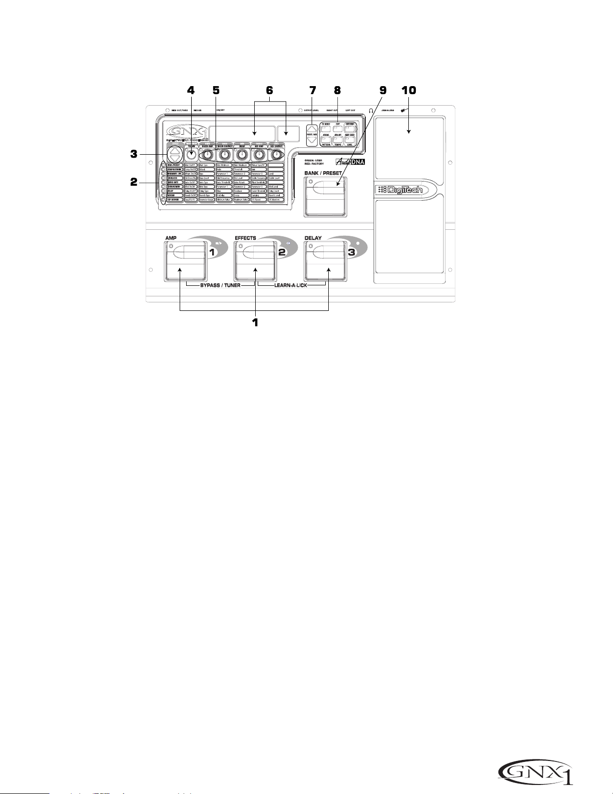
1.1-3 Footswitches - Depending on the currently selected mode,these 3
footswitches are used to select Presets,access the Tuner, turn individual effects
on and off,change Amp Channels,select functions in Learn-A-Lick mode, or
bypass the GNX1.
2. Matrix - The Matrix LEDs provide a visual indication of active effects for the
currently selected Preset in performance mode,or the currently selected effect
row in edit mode.
3. Effect Select Buttons - The Effect Select buttons are used in conjunction
with the Matrix LEDs to choose the row of effects you wish to edit.
4. Status Button - In Performance mode, the Status button is used to select
the Green or Red Amp Channel.The Status button is also used to enable the
Amp and Cabinet Warping feature (indicated by a yellow LED next to the Status
button).In Edit mode it is used to change the on/off status of the selected
effect,select the Green or Red Channel for EQ edits,or select a controller type
for Expression Assignment.
5. Parameter Knobs - In performance mode, these 5 knobs are used to select
Amp Models,Speaker Cabinets,and Warp the Models.In Green or Red mode,
they adjust the Amp Gain,EQ and Level for the Green and Red Amp Channels.
In Edit mode, they are used to adjust the Parameters listed in the column
directly below each knob for the currently selected row of Effects.
6. Display - The Display consists of six alpha-numeric green characters,and two
red numeric digits.The Display provides information for several different
functions depending on the mode that has been selected.In Performance
mode, the Display will show the currently selected Preset name and number.
The Display will also show Bank names when changing banks,and momentarily
flash the active Amp Channel when the Amp Channel is switched.In Edit mode,
the alpha-numeric Display will show the currently selected Effect Parameter and
value or status of the Parameter. In Tuner mode, the numeric Display will show
the note played and provide sharp or flat indications. In Learn-A-Lick mode,
the alpha-numeric display shows the currently selected function and the numeric
Display provides an elapsed time for record and playback.
1.1-3 Pedales de disparo - Dependiendo del modo activo,estos 3 pedales de
disparo se usan para elegir Presets,acceder al afinador,activar o desactivar efectos individuales,cambiar canales de amplificador,elegir funciones en el modo
Learn-A-Lick o anular el GNX1.
2. Matriz - La Matriz de LEDs le ofrece una indicación visual de los efectos
activos en el preset elegido en ese momento en el modo de ejecución,o de la
fila del efecto activo en el modo de edición.
3. Botones selectores de efectos - Estos botones selectores de efectos se
usan junto con la matriz de LEDs para escoger las filas de efectos que quiera
editar.
4. Botón Status - En el modo de ejecución, este botón se usa para elegir el
canal de amplificación verde o rojo. Este botón también se usa para activar la
función de deformación de amplifidor y recinto (indicada por un piloto amarillo
al lado de este botón).En el modo de edición, este botón se usa para cambiar el
estado on/off del efecto elegido,elegir el canal verde o rojo para las ediciones
EQ o elegir un tipo de controlador para la asignación de expresión.
5. Mandos Parameter - En el modo de ejecución,estos 5 mandos se usan para
elegir los modelos de amplificador, recintos acústicos y deformar los modelos.
En el modo verde o rojo, ajustan la ganancia de amplificación, EQ y nivel para los
canales de amplificador verde o rojo. En el modo de edición se usan para ajustar
los parámetros relacionados en la columna que está justo debajo de cada uno
de los mandos para la fila de efectos activa.
6. Pantalla - La pantalla consta de seis caracteres verdes alfanuméricos,y dos
dígitos numéricos rojos.Le ofrece información de diversas funciones dependiendo del modo elegido.En el modo de Ejecución,la pantalla le mostrará el pre-
set elegido activo,con nombre y número.También le mostrará los nombres de
los bancos cuando esté cambiando de uno a otro,y en ella parpadeará momentáneamente el canal de amplificador activo cuando lo active.En el modo de
Edición la pantalla alfanumérica le mostrará el parámetro de efecto elegido en
ese momento y su valor o estado del parámetro.En el modo de Afinador,la
pantalla numérica le mostrará la nota tocada,así como indicaciones de bemol o
sostenido.En el modo Learn-A-Lick,la pantalla alfanumérica le muestra la fun-
ción activa mientras que la pantalla numérica le indica el tiempo transcurrido de
grabación y reproducción.
3
Page 8

SECTION ONE - INTRODUCTION
7. Data Up/Down Buttons -These buttons are used to increase and decrease
the currently selected Preset in Performance mode, value of currently displayed
parameter in edit mode, the value or status of the currently selected Utility or
Rhythm function,or the alpha-numeric character in the naming procedure.
8. Mode Buttons - These 6 buttons are used to select various modes in which
the GNX1 will function.The Exit button performs a single function while the
other 5 buttons perform dual functions based upon the current operation of
the GNX1.The buttons are labeled as follows:
A) FX Mode -The FX Mode button selects whether the 1-3 footswitches
will recall Presets within the selected Bank,or act as on/off switches for
the individual effects in the currently selected Preset.The FX Mode button
will light when the switches are performing effects on/off functions.The
function of this button changes to select the previous character when
naming a Preset,or select the previous menu in Utility mode.
SECCIÓN UNO - INTRODUCCIÓN
7. Botones Data Arriba/Abajo - Estos botones se usan para aumentar y disminuir
el preset activo en ese momento en el modo de ejecución,el valor del parámetro
visualizado en ese momento en el modo de edición,el valor o estado de la función
de utilidades o rítmica activa entonces,o el caracter alfanumérico en el proceso de
nombrado.
8. Botones Mod -Estos 6 buttons se usan para elegir los diversos modos en
los que funcionará el GNX1.El botón Exit realiza una función única mientras
que los otros 5 botones tienen funciones dobles dependiendo de la operación
activa del GNX1.Los botones están indicados de la siguiente forma:
A) FX Mode - Este botón elige si los pedales de disparo 1-3 cargarán
Presets dentro del banco elegido,o actuarán como interruptores on/off
para los efectos individuales en el preset activo.El botón FX Mode se iluminará cuando los interruptores estén actuando como on/off de efectos.
Este botón elige el carácter anterior durante el proceso de nombrado de
un preset,o elige el menú anterior en el modo de utilidades.
B) Exit -This button acts as a panic button and is used to escape from
any mode or level of editing returning the GNX1 to Performance mode.
C) Rhythm -The Rhythm button is used to access the Rhythm Trainer
drum loop feature in the GNX1.When the Rhythm feature is selected,the
LED will light,the drum loop begins playing,and the bottom row of Mode
buttons can be used in conjunction with the Data Up and Down buttons
to select and edit the Pattern,Tempo, and Level. The function of this button
changes to select the next character when naming a Preset,or select the
next menu in Utility mode.
D) Store -The Store button is used to save your custom edits to the user
Presets.The function of this button changes to select Pattern in Rhythm
mode.
E) Utility -The Utility button provides access to several global functions
including Output Mode, Target System Setup,Volume Pedal Update,VSwitch,Pedal Calibration,Bank Names, MIDI Channel, Sysex Dumps,MIDI
Mapping,MIDI Merge, and Factor y Reset menus.The function of this
button changes to select Tempo in Rhythm mode.
F) Amp Save - This button is used to store any changes made to the
characteristics of Amps and Cabinets (tone, gain, level,amp type , cabinet
type, warp, or cabinet tuning) as HyperModels™ for later retrieval or
warping.The function of this button changes to select Level in Rhythm
mode.
9. Bank/Preset Footswitch -The function of this switch will change depending
upon whether the FX Mode is active or inactive.When FX Mode is active, this
switch is used to change Presets.Successive presses of this switch will advance
through all User Presets (indicated by a green LED),and Factory Presets
(indicated by a red LED).Pressing and holding this switch will descend
backwards through all User and Factory Presets.When FX Mode is inactive,
successive presses of this switch will advance through all User (indicated by a
green LED) and Factory (indicated by a red LED) Banks.Pressing and holding
this switch will descend backwards through all User and Factory Banks.
10. Expression Pedal - The Expression Pedal controls the assigned Effect
Parameter in real time. Most Parameters within the GNX1 are available for
Expression Pedal assignment. Applying extra pressure to the toe of the
Expression Pedal will switch between controlling the assigned Parameter and
turning the Wah on and off.
B) Exit - Este botón actúa como un botón de pánico y se usa para salir
de cualquier modo o nivel de edición,devolviendo el GNX1 al modo de
ejecución normal.
C) Rhythm - El botón Rhythm se usa para acceder a la función de bucle de
batería del Entrenador rítmico del GNX1.Cando se elige esta función,el
piloto se enciende, el bucle de batería comienza a reproducirse y puede
usar la fila inferior de botones de modo junto con los botones Data arriba
y abajo para elegir y editar el patrón,tempo y nivel.Este botón pasa a elegir
el siguiente carácter en los procesos de nombrado de un preset,o elige el
siguiente menú en el modo de utilidades.
D) Store - Este botón se usa para almacenar sus ediciones personales en
los presets de usuario.La función de este botón cambia para elegir los
patrones en el modo rítmico.
E) Utility - Este botón le permite acceder a diversas funciones globales
como las de modo de salida,configuración de sistema de destino,actualización de pedal de volumen,V-Switch,calibración de pedal, nombres de
banco,canal MIDI, volcados Sysex,mapa MIDI,mezcla MIDI y reinicialización
a valores de fábrica.Este botón se ocupa de elegir el tempo en el modo rítmico.
F) Amp Save - Este botón se usa para almacenar cualquier cambio que haga
en las características de los amplificadores y recintos (sonido,ganancia, nivel,
tipo de amplificador,tipo de recinto,deformación o afinación de recinto) como
HyperModels™ para su recuperación o deformación posteriores.Este botón
se ocupa de elegir el nivel en el modo rítmico.
9. Pedal Bank/Preset - La función de este interruptor cambiará dependiendo
de si el modo FX está activo o no.Cuando el modo FX está activo, este interruptor se usa para cambiar los presets.Las pulsaciones sucesivas de este interruptor harán que vaya avanzando a través de todos los presets de usuario (indicados por un LED verde),y los presets de fábrica (indicados por un LED rojo).
El mantener pulsado este interruptor hará que vaya pasando hacia atrás por
todos los presets.Cuando el modo FX no esté activo,las pulsaciones sucesivas
de este interruptor harán que vaya pasando por todos los bancos de usuario
(indicados por un piloto verde) y de fábrica (piloto rojo).El mantener pulsado
este interruptor hará que vaya desplazándose hacia atrás por los bancos.
10. Pedal de expresión - El pedal de expresión controla el parámetro de efecto asignado en tiempo real. En el GNX1 puede asignar la mayoría de los
parámetros al pedal de expresión. El aplicar una presión extra en la puntera de
este pedal hará que cambie entre el control del parámetro asignado y la activación on/off del Wah.
4
Page 9
SECTION ONE - INTRODUCTION SECCIÓN UNO - INTRODUCCIÓN
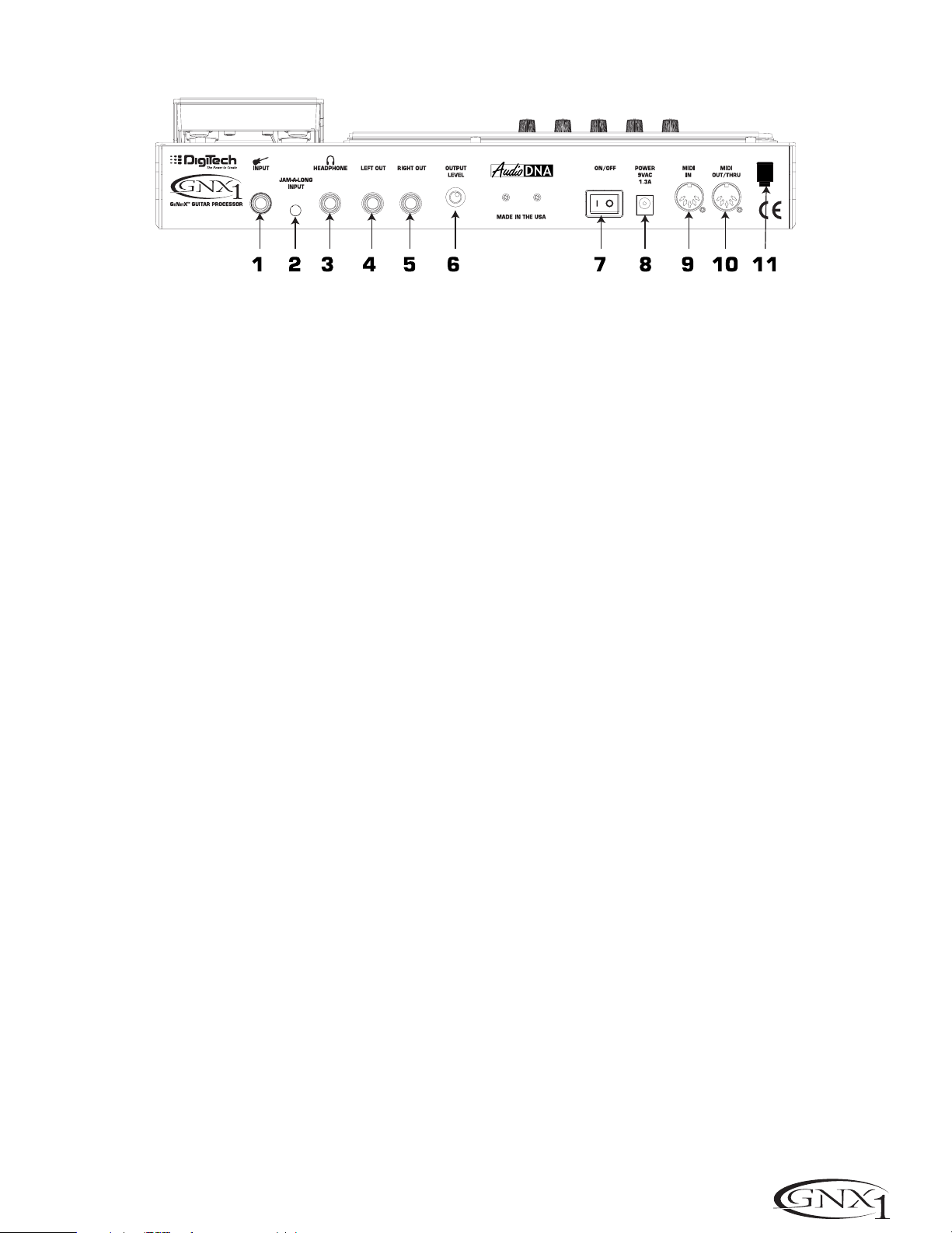
Rear Panel
1. Input Jack - Connect your instrument to this jack.
2. Jam-A-Long Jack - Use an 1/8” stereo plug to connect this jack to the
output of a tape or CD player.This allows you to jam along with the music, or
to record a musical passage into the Learn-A-Lick phrase recorder.
3. Headphone Output - Connect stereo headphones to this jack. Be sure to
set the Target System Setup mode to Direct when listening through
Headphones (see page 34 for more information on selecting the Target System
Setup).Do not connect a mono plug to this jack as doing so may damage the
output driver.
4. Left Output - Connect from this jack to the input of an amplifier,input of a
power amp,or line input of a mixing console.
Panel trasero
1. Clavija de entrada - Conecte su instrumento a esta entrada.
2.Toma Jam-A-Long - Use un conector stereo de 3,5 mm para conectar esta
toma con la salida de su pletina o reproductor CD. Esto le permite improvisar
junto con la música,o grabar un pasaje musical en la grabadora de frases musicales Learn-A-Lick.
3. Salida de auriculares - Conecte unos auriculares stereo a esta salida.
Asegúrese de ajustar el modo de configuración de sistema de destino a Direct
cuando use los auriculares (vea en la página 34 más información acerca de esto).
No conecte una clavija mono a esta salida ya que eso podría dañar el cabezal de
salida.
4. Salida izquierda -Conecte esta salida a la entrada de un amplificador, la
entrada de una etapa de potencia,o la entrada de línea de una mesa de mezclas.
5. Right Output - Use this jack in conjunction with the Left Output for stereo
applications.Connect from this output to the input of a second amplifier, or the
right input of a stereo power amp.
6. Output Level -This knob controls the overall volume level of the GNX1.
7. Power Switch -Turns the power to the GNX1 on and off.
8. Power Input - Connect only the provided DigiTech PS0913B power supply
to this jack.
9. MIDI In - This jack is used to receive all incoming MIDI data intended to
control the GNX1.Connect from this jack to the MIDI out of a computer,
sequencer, MIDI controller,or MIDI storage device.
10. MIDI Out/Thru - This jack is used for all MIDI data being sent out of the
GNX1.Connect from this jack to the MIDI in of a computer, or external MIDI
recording device.When enabled, the MIDI Thru function of this jack sends out
the same information that is received at the MIDI In of the GNX1.
11. Strain Relief -This is used to secure the power cord and prevent possible
disconnects during performance.
5. Salida derecha - Use esta salida junto con la salida izquierda para aplicaciones stereo.Conecte esta salida a la entrada de un segundo amplificador,o a
la entrada derecha de una etapa de potencia stereo.
6. Nivel de salida - Este mando controla el nivel de volumen global del GNX1.
7. Interruptor Power - Enciende o apaga el GNX1.
8. Entrada Power Conecte a esta toma solo la fuente de alimentación DigiTech
PS0913B.
9. MIDI In - Este conector se usa para recibir todos los datos MIDI entrantes
con los que quiera controlar el GNX1.Conecte esta entrada a la toma MIDI
out de un ordenador,secuenciador,controlador MIDI o unidad de almacenamiento MIDI.
10. MIDI Out/Thru - Este conector se usa para todos los datos MIDI que sean
emitidos desde el GNX1.Conecte esta clavija a la toma MIDI in de un ordenador o unidad de grabación MIDI exterior.Cuando esté activa, la función MIDI
Thru de esta clavija emitirá la misma información que sea recibida en la toma
MIDI In del GNX1.
11. Clavija anti-tirones - Se usa para fijar el cable de alimentación y evitar
posibles desconexiones accidentales durante la ejecución.
5
Page 10
SECTION ONE - INTRODUCTION
Getting Started
SECCIÓN Uno - INTRODUCCIÓN
Puesta en marcha
Making Connections
Before connecting the GNX1,make sure that the power to your amplifier is
turned off,and that the power switch on the rear panel of the GNX1 is in the
off position.
There are several different connection options available when using the GNX1.
You may run mono into an amp or power amp,stereo into two amps or a
stereo power amp,direct into a mixing console, or a combination of these .The
following diagrams show the connections for some of these options.
NOTE:The type of amplification system the GNX1 will be used in should be
selected in the Target System Setup of the Utility menu. See page 34 for
more information on selecting the Target System Setup.
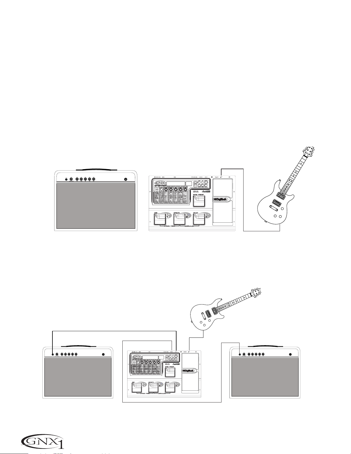
Mono Operation
Connect your guitar to the input of the GNX1.Connect the Left output of the
GNX1 to the instrument input on your amplifier,or to the line input of a power
amp.Select Mono as the Output mode in the Utility menu.See page 34 for
more on selecting the Output mode.
Guitar Input/Effect Return
Entrada guitarra/retorno efectos
Conexiones
Antes de conectar el GNX1,asegúrese que su amplificador esté apagado y que
el interruptor de encendido del panel trasero del GNX1 esté en la posición off.
Cuando use el GNX1 dispone de varias opciones de conexión posibles entre las
que elegir. Puede hacer una conexión en mono a un amplificador o etapa de
potencia,en stereo a dos amplificadores o una etapa de potencia stereo,directo
a una mesa de mezclas o usar una combinación de estas conexiones.Los diagramas siguientes le muestran las conexiones para algunas de esas opciones.
NOTA: El tipo de sistema de amplificación con el que será usado el GNX1
debe ser elegido en la Configuración de sistema de destino del menú de
utilidades.Vea la página 34 para más información acerca de estos ajustes.
Funcionamiento Mono
Conecte su guitarra a la entrada del GNX1.Conecte la salida izquierda del
GNX1 a la entrada de instrumento de su amplificador o a la entrada de línea de
una etapa de potencia.Elija Mono como modo de salida en el menú de utilidades.Vea la página 34 para más información acerca del modo de salida.
Left Output
Salida izquierda
Input
Entrada
Stereo Operation
For stereo operation connect the guitar to the input of the GNX1.Connect
from the GNX1’s Left output to the input of one amplifier or channel of a
power amp.Connect from the Right output of the GNX1 to a second amplifier,
or to a second channel of a power amp.Select Stereo as the Output mode in
the Utility menu.See page 34 for more on selecting the Output mode.
Guitar Input/Effect Return
Entrada guitarra/retorno efectos
Left Output
Salida izquierda
Right Output
Salida derecha
Funcionamiento Stereo
Para un funcionamiento stereo conecte la guitarra a la entrada del GNX1.
Conecte la salida izquierda del GNX1 a la entrada de un amplificador o a un
canal de una etapa de potencia.Conecte la salida derecha del GNX1 a un
segundo amplificador o a un segundo canal de la etapa de potencia.Elija Stereo
como modo de salida en el menú de utilidades.Vea la página 34 para más información acerca de la selección del modo de salida.
Guitar Input/Effect Return
Input
Entrada
Entrada guitarra/retorno efectos
6
Page 11
SECTION ONE - INTRODUCTION SECCIÓN Uno - INTRODUCCIÓN
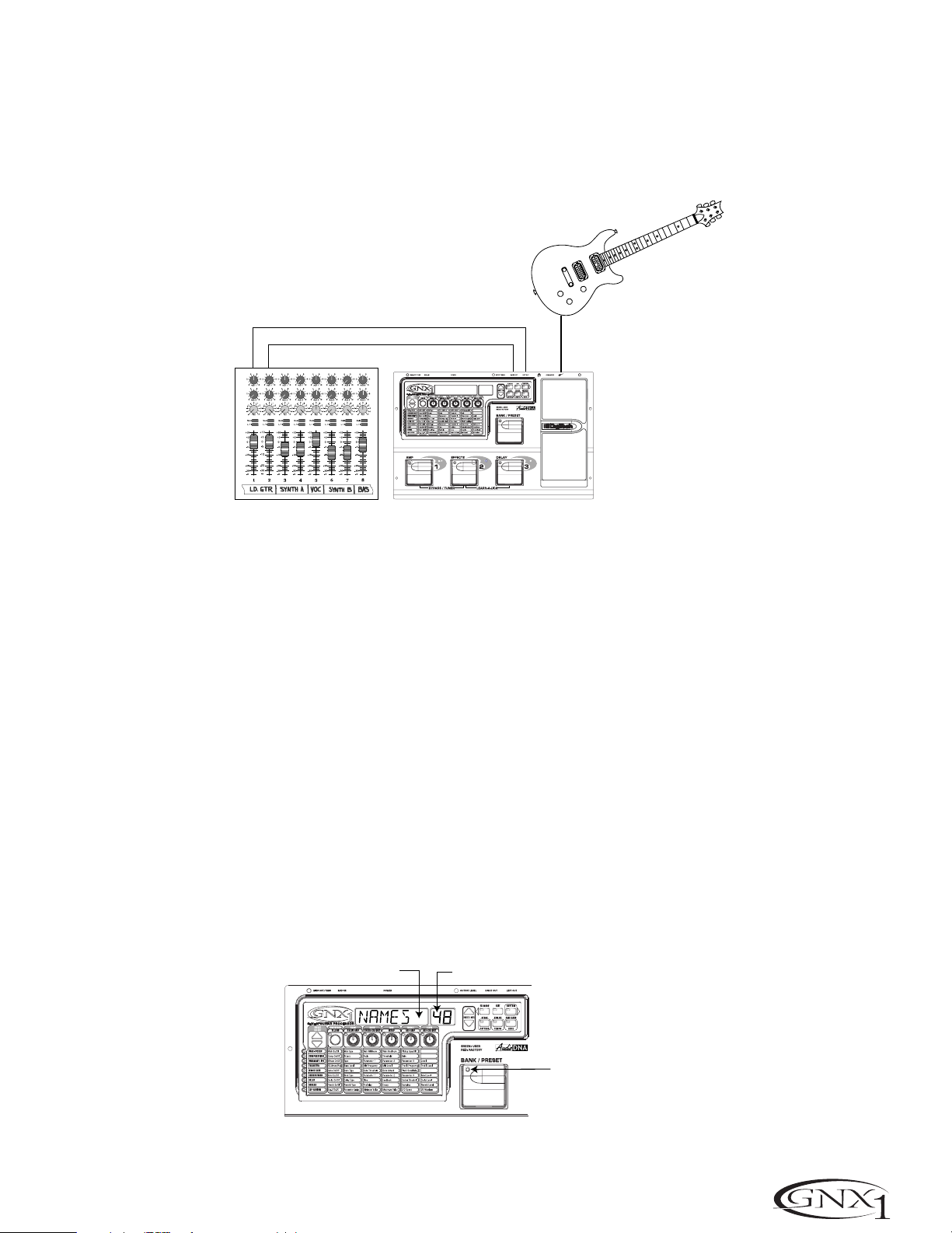
Direct to a Mixing Console
The GNX1 can be connected directly to the inputs of a house PA system,or to
a recording console.Connect the guitar to the input of the GNX1. Connect
from the outputs of the GNX1 to the channel inputs of the mixing console.If
the GNX1 is to be used in Stereo mode,set the pan controls of the mixer hard
left and right,and select stereo as the output mode in the GNX1’s Utility menu.
See page 34 for more information on the output mode.
Left Output/Salida izquierda
Directo a una mesa de mezclas
Puede conectar el GNX1 directamene a las entradas de un sistema PA, o a una
mesa de mezclas.Conecte la guitarra a la entrada del GNX1. Conecte después
las salidas del GNX1 a los canales de entrada de la mesa de mezclas.Si va a usar
el GNX1 en el modo stereo,ajuste los controles de panorama de la mesa de
mezclas completamente a la izquierda y a la derecha y elija stereo como modo
de salida en el menú de utilidades del GNX1.Vea en la página 34 más información acerca de estos ajustes.
Right Output/Salida derecha
Applying Power
Once the audio connections have been made,turn the Output Level on the rear
panel of the GNX1 all the way down (counterclockwise).Connect the PS0913B
to the power jack on the back of the GNX1 and the other end to an AC outlet.
Turn the power switch of the GNX1 to the On position. Turn the power to
your amplifier(s) on. Set the amp(s) to a clean tone and set the tone controls to
a flat EQ response (on most amps,this would be 0 or 5 on the tone controls).
Turn the Output Level of the GNX1 up to achieve the desired volume level.
About the GNX1
The Presets
Presets are named and numbered locations of programmed sounds which reside
in the GNX1.Presets can be recalled with the Footswitches or the Data Up and
Down Switches.The GNX1 comes with 48 Factor y and 48 User Presets
available.The Factory Presets will not allow you to store any changes to them.
The User Presets are locations where your creations may be stored.From the
factory,the 48 User Presets are exact duplicates of the 48 Factory Presets.This
allows you to make your own Presets without the worry of losing any of the
original sounds that the GNX1 came with.When you select a Preset, the name
of the Preset will be shown in the green alpha-numeric Display and the number
of the Preset will be shown in the red numeric Display. The LED at the top of
the Bank/Preset Footswitch will light green to indicate a User Preset and red to
indicate a Factory Preset.
Input
Entrada
Encendido
Una vez que haya realizado las conexiones audio,baje a tope el nivel de salida
del panel trasero del GNX1 (tope izquierdo).Conecte la fuente de alimentación
PS0913B a la entrada de corriente de la parte trasera del GNX1 y el otro
extremo a una salida de corriente alterna. Coloque el interruptor de encendido
del GNX1 en la posición On.Encienda después también su amplificador(s).
Ajuste el amplificador(s) a un sonido limpio y ajuste los controles de tono a una
respuesta EQ plana (esto suele estar sobre el 0 o el 5 en los controles de
tono). Aumente el nivel de salida del GNX1 hasta conseguir el nivel de volumen
que quiera.
Acerca del GNX1
Los Presets
Los Presets son posiciones con nombres y números de sonidos programados
que residen en el GNX1.Los presets pueden ser cargados o activados con los
pedales de disparo o con los interruptores Data arriba o abajo. El GNX1 viene
con 48 presets de fábrica y 48 de usuario.Los presets de fábrica no le permitirán almacenar datos sobre ellos.Los presests de usuario son posiciones en las
que puede almacenar sus creaciones.Cuando sale de fábrica, los 48 presets de
usuario son réplicas exactas de los 48 presets de fábrica.Esto le permite crear
sus propios presets sin preocuparse de perder ninguno de los sonidos originales
con los que viene el GNX1.Cuando elige un Preset, en la pantalla alfanumérica
aparecerá el nombre del mismo,mientras que su número será visualizado en la
pantalla numérica roja. El piloto LED que está encima del pedal de disparo
Bank/Preset se iluminará en verder para indicar un preset de usuario o en rojo
para indicar uno de fábrica.
Preset Names
Nombres de preset
Preset Numbers
Números de preset
Green=User
Red=Factory
Verde=usuario
Rojo=fábrica
7
Page 12
SECTION ONE - INTRODUCTION
Performance Mode
When you first apply power to the GNX1,it will power up in Performance
mode. This is the top level mode and the mode used while you are performing.
While in Performance mode,the Display will show the currently selected
Preset’s name and number. The vertical LEDs on the Matrix will indicate the
Effects which are active in the selected Preset.From Performance mode, you
have access to all of the Presets within the GNX1 with your choice of assigning
the Footswitches to either Preset Mode or FX Mode.
SECCIÓN Uno - INTRODUCCIÓN
Modo de ejecución
Cuando encienda por primera vez el GNX1,se encenderá en el modo de ejecución.Este es el nivel superior de los modos y es el modo usado mientras está
ejecutando presets.Mientras esté en este modo,la pantalla le mostrará el nombre y el número del preset activo entonces. Los pilotos verticales de la matriz
le indicarán los efectos que están activos en el preset elegido.Desde el modo
de ejecución,puede acceder a todos los presets del GNX1 pudiendo asignar los
pedales de disparo al modo de preset o al modo FX.
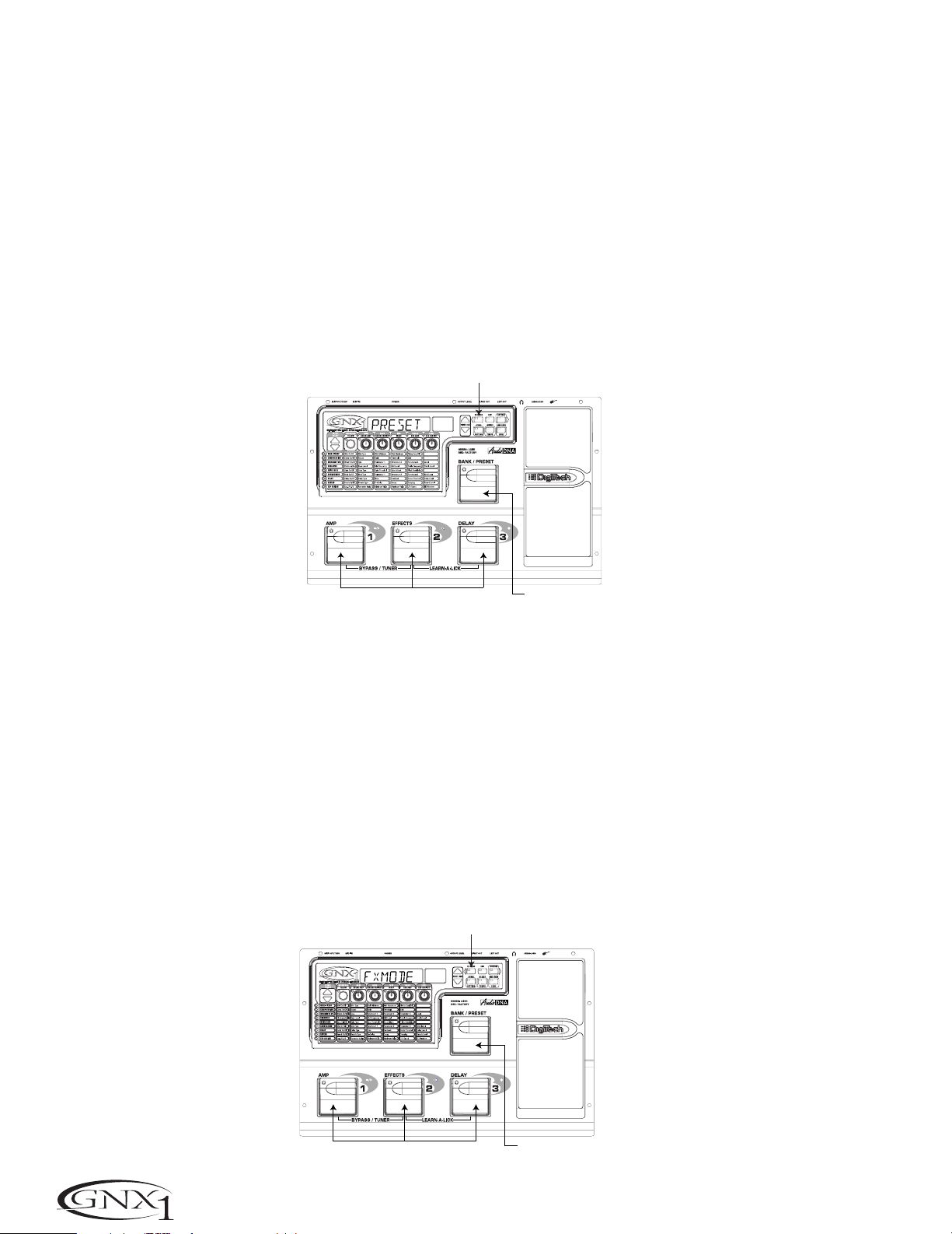
Preset Mode
Preset Mode is the default mode from the factory. In Preset mode, the 1-3
Footswitches will call up Presets in the currently selected Bank. The Bank
Switch is used to select the 16 User/Factory Banks. Successive presses of the
Bank/Preset switch will advance forward through all User/Factory Banks.
Pressing and holding the Bank/Preset switch will scroll backwards through all
User/Factory Banks. Once the desired Bank has been selected, the LEDs in
the 1-3 Footswitches will flash indicating that a Preset within that bank needs
to be selected in order to activate the Bank.If no Preset selection is made
within 5 seconds,The GNX1 will return to the last Bank and Preset that had
been active.
LED Off Indicates / Los LED apagados indican
Preset Mode el modo Preset
Switches Select Presets
Los interruptores eligen los Presets
FX Mode
FX mode is another mode of operation which can be used during a
performance. The FX Mode button (located to the right of the Display) is
used to switch between Preset and FX Modes.When the FX mode is active,
the FX Mode button will light.In FX Mode, the 1-3 Footswitches toggle the
designated Effects.Depending on which effects are active in the current
Preset,these switches may have one or more LEDs lit indicating the status of
these effects.Footswitch 1 toggles between the Green,Red, and Yellow amp
channels.Footswitch 1 will light either green,red,or yellow indicating
whether the Green Channel,Red Channel, or a Warped combination of the
Green and Red Channels is active.Footswitch 2 turns on and off the
Chorus/Mod Effects Module. Footswitch 3 turns on and off the Delay. The
Bank/Preset switch is used to change Presets.Successive presses of the
Bank/Preset switch will advance forward through all Factory and User
Presets.Pressing and holding the Bank/Preset switch will scroll backwards
through all Factory and User Presets.
LED On indicates FX Mode
El piloto encendido indica el modo FX
Modo de Preset
Este es el modo por defecto cuando la unidad sale de fábrica.En el modo de
Preset,los pedales de disparo 1-3 cargarán los Presets en el banco activo en
ese momento.El interruptor Bank se usa para elegir los 16 bancos de usuario
/ fábrica.Las pulsaciones sucesivas del interruptor Bank/Preset harán que vaya
pasando por todos los bancos de usuario/fábrica.Si mantiene pulsado este
interruptor irá pasando por los bancos hacia atrás.Una vez que haya elegido
el banco que quiera,los pilotos de los pedales de disparo 1-3 parpadearán
para indicar que tiene que elegir un preset dentro de ese banco para activarlo.Si no elige ningún preset en 5 segundos,el GNX1 volverá al último banco
y preset que hubiese estado activo.
Selects Banks
Elige los bancos
Modo FX
El modo FX es otro modo operativo que puede usar durante una ejecución.
El botón FX Mode (situado a la derecha de la pantalla) se utiliza para cambiar
entre los modos Preset y FX.Cuando el modo FX está activo, el piloto del
botón FX Mode se ilumina.En el modo FX, los pedales de disparo 1-3 cambian los efectos designados.Dependiendo de los efectos que estén activos en
el preset elegido,estos interruptores puede que tengan un solo LED iluminado o varios,para indicar el estado de estos efectos. El pedal de disparo 1
cambia entre los canales de amplificador verde,rojo y amarillo.El pedal de
disparo 1 se iluminará en esos colores para indicar que está activo el canal
verde, el canal rojo o una combinación deformada de ambos canales. El pedal
de disparo 2 activa o desactiva el módulo de efectos Chorus/Mod.El pedal de
disparo 3 activa o desactiva el retardo. El interruptor Bank/Preset se usa para
cambiar los Presets.Las pulsaciones sucesivas sobre este interruptor
Bank/Preset harán que vaya pasando por los distintos presets de fábrica y de
usuario.Si mantiene pulsado este interruptor irá pasando hacia atrás por los
diferentes presets.
Switches Toggle Effects
Interruptores activan efectos
Selects Presets
Elige presets
8
Page 13
SECTION ONE - INTRODUCTION SECCIÓN Uno - INTRODUCCIÓN
The Footswitches
As explained previously, Preset Mode utilizes Footswitches 1-3 to select Presets,
and the same switches will toggle Effects in FX Mode. However,these
footswitches are also used to access other functions in the GNX1.Pressing the
1 and 2 Footswitches simultaneously,or pressing the currently lit Footswitch
(in Preset mode) will bypass the GNX1.Pressing and holding the 1 and 2
Footswitches simultaneously will access the Tuner mode. Pressing the 2 and 3
Footswitches simultaneously will activate the Learn-A-Lick mode.In the
Learn-A-Lick mode, the 1-3 switches will activate the various Learn-A-Lick
functions.
Los pedales de disparo
Como hemos explicado anteriormente, el modo Preset usa los pedales de disparo 1-3 para elegir los Presets,y estos mismos interruptores cambian los efectos en el modo FX. Sin embargo, estos pedales de disparo se usan también para
acceder a otras funciones en el GNX1.Si pulsa simultáneamente los pedales
de disparo 1 y 2,o si pulsa el pedal de disparo iluminado en ese momento
(en el modo Preset),anulará o dejará en bypass el GNX1.El mantener pulsados
simultáneamente los pedales de disparo 1 y 2 le dará acceso al modo de afinador. El pulsar simultáneamente los pedales de disparo 2 y 3 activará el
modo Learn-A-Lick.En este modo,los tres interruptores activarán las distintas
funciones del Learn-A-Lick.
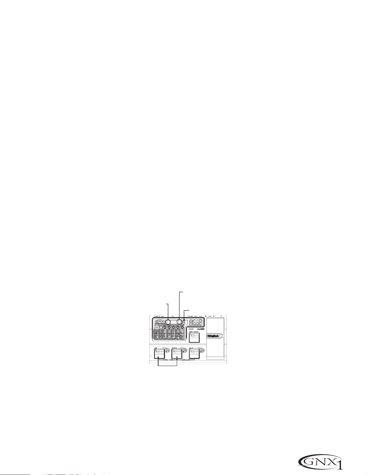
The Expression Pedal
As you go through the different Presets in the GNX1, you will find that the
expression pedal has different functions.This pedal can be assigned to control
three different parameters in each Preset.Rocking the Expression Pedal back
and forth will change the value of the assigned parameters.You can assign
minimum and maximum values (stop points) for each parameter that you
control with the pedal.The Expression Pedal also includes a feature called VSwitch which allows you to override the Parameters assigned to the Expression
Pedal and replace its assignment with the Wah.See page 32 for more
information on assigning the Expression Pedal.
Bypass Mode
The GNX1 can be bypassed for a clean,unprocessed,straight guitar tone.
Bypass mode disengages all Modeling and effects.To bypass the GNX1 in Preset
mode, press the Footswitch representing the currently active Preset (the 1-3
footswitch that is lit),or press Footswitch 1 and 2 simultaneously.To bypass
the GNX1 while in FX Mode, press the 1 and 2 Footswitches simultaneously.
When the GNX1 is bypassed,the Display will read BYPASS and all LEDs in the
Matrix will turn off.Pressing any Footswitch will exit Bypass and return to the
last Preset used.None of the Matrix or Programming buttons are available in
Bypass mode.
Tuner Mode
The Tuner in the GNX1 allows you to quickly tune or check the tuning on your
guitar. Enter Tuner mode by pressing and holding Footswitches 1 and 2
simultaneously. The Display will briefly show TUNER indicating that you are in
Tuner mode.To begin tuning,play a note on your guitar (a harmonic at the 12th
fret usually works best).The red numeric Display will show the note being
played,and the green alpha-numeric display will indicate whether the note is
sharp or flat. Arrows to the left (<<<) indicate the note is sharp and should be
tuned down. Arrows to the right (>>>) indicate the note is flat and should be
tuned up.When your note is in tune, the Display will read -><- .
Arrows Pointing Right
indicate note is flat
Las flechas a la derecha
indican nota bemolada
El pedal de expresión
Según vaya pasando por los distintos Presets del GNX1,obser vará que el pedal
de expresión tiene distintas funciones.Puede asignar este pedal para controlar
tres parámetros distintos en cada Preset.El girar el pedal de expresión adelante y atrás hará que cambie el valor de los parámetros asignados.Puede asignar valores mínimos y máximos (puntos de parada) para cada parámetro que
vaya a controlar con el pedal.El pedal de expresión también incluye una función
llamada V-Switch que le permite anular los parámetros asignados al pedal de
expresión y sustituir esa asignación por el Wah.Vea en la página 32 más información acerca de la asignación del pedal de expresión.
Modo de anulación o bypass
El GNX1 puede ser anulado o colocado en bypass para conseguir un sonido de
guitarra limpio,directo y sin procesado. Este modo bypass desactiva todos los
efectos y el modelado.Para anular el GNX1 en el modo de Preset, pulse el
pedal de disparo que represente al Preset activo (el pedal de disparo 1-3 que
esté iluminado),o pulse simultáneamente el pedal de disparo 1 y 2. Para anular el GNX1 mientras esté en el modo FX,pulse simultáneamente los pedales
de disparo 1 y 2.Cuando el GNX1 está en bypass, la pantalla le indicará
BYPASS y todos los pilotos de la matriz se apagan. La pulsación de cualquiera
de los pedales de disparo hará que salga de esta anulación y le devolverá al
último preset usado.En el modo de anulación no puede usar ninguno de los
botones de la matriz o de programación.
Modo de afinador
El afinador del GNX1 le permite rápidamente afinar o comprobar la afinación
de su guitarra. Acceda a este modo manteniendo pulsados simultáneamente los
pedales de disparo 1 y 2. En la pantalla aparecerá brevemente TUNER para
indicarle que está en el modo de afinador. Para comenzar la afinación, toque una
nota en su guitarra (un armónico en el 12avo traste suele funcionar bien).La
pantalla roja numérica le mostrará la nota que esté tocando,y la pantalla
alfanumérica verde le indicará si la nota está bemolada o sostenida.Las flechas a
la izquierda (<<<) le indican que la nota está sostenida y que debería disminuir
su tono.Las flechas a la derecha (>>>) indican que el tono está bemolado y que
debería aumentarlo.Cuando la nota esté en su tono perfecto,en pantalla aparecerá -><- ..
Arrows Pointing Left
indicate note is Sharp
Las flechas a la izquierda
indican nota sostenida
Note played/Nota tocada
Press and Hold to Activate Tuner
Mantenga pulsado para activar el afinador
In Tuner mode,you can select your tuning reference with the Data Up/Down
buttons. The default factory setting is A=440 Hz.The tuning reference ranges
from 427 Hz to 453 Hz,which is the equivalent of ± 50 cents (1/2 semitone) in
either direction from 440 Hz.When you scroll below 427 Hz,you will also find
alternate dropped tunings.Alternate tunings are REF A& (A=Ab),REF G
(A=G),and REF G& (A=Gb).The display window will briefly flash the currently
selected tuning preference.
Exit tuner mode by pressing any of the Footswitches.
En el modo de afinador, puede elegir su referencia de afinación con los botones
Data arriba/abajo.El valor de fábrica por defecto es A=440 Hz.El rango de
referencias de afinación va desde los 427 Hz a los 453 Hz, lo que es equivalente
a ± 50 centésimas (1/2 semitono) en ambas direcciones del 440 Hz. Cuando
pase por debajo de los 427 Hz,también encontrará algunas referencias de afinación alternativas a otros tonos.Estas afinaciones alternativas son REF A&
(A=Ab),REF G (A=G) y REF G& (A=Gb).En la pantalla parpadeará breve-
mente la referencia de afinación elegida.
Para salir del modo de afinador no tiene más que pulsar cualquiera de los ped-
ales de disparo.
9
Page 14

SECTION ONE - INTRODUCTION
Jam-A-Long
The Jam-A-Long feature allows you to connect a Tape, CD,or MP3 player to the
GNX1,and Jam with your favorite artists.The signal from your Tape , CD, or MP3
player is output through the left and right, and headphone outputs of the
GNX1. To use the Jam-A-Long feature,connect the headphone output of your
Tape , CD, or MP3 player to the Jam-A-Long Input on the rear panel of the
GNX1 using an 1/8” stereo cable.Then press play on your Tape,CD,or MP3
player.
SECCIÓN Uno - INTRODUCCIÓN
Jam-A-Long
La función Jam-A-Long le permite conectar un reproductor de cinta,CD o MP3
al GNX1,e improvisar así con sus músicos favoritos.La señal de su reproductor
de CD,MP3 o cinta es emitida a través de las salidas izquierda,derecha y de
auriculares del GNX1. Para usar la función Jam-A-Long, conecte la salida de
auriculares de su unidad reproductora a la Entrada Jam-A-Long del panel
trasero del GNX1 usando un cable stereo de 3,5 mm.Después de conectarlo,
pulse Play en su reproductor.
Learn-A-Lick Mode
The Learn-A-Lick function allows you to record a 9 second passage of music
and play it back as slow as 1/4 speed with no change in pitch. This is very useful
for picking out the notes of a fast guitar solo.
There are 6 functions for Learn-A-Lick.They are:
• Stop (Controlled by the number 1 Footswitch)
• Rewind (Controlled by the number 2 Footswitch)
• Play (Controlled by the number 1 Footswitch)
• Record (Controlled by the number 3 Footswitch)
• Tempo Down (Controlled with Data Down button)
• Tempo Up (Controlled by the Data Up button)
Using Learn-A-Lick
1. Connect the output of your Tape, CD,or MP3 player’s headphone output
to the Jam-A-Long input jack on the rear panel using an 1/8” stereo plug.
Set the level of the player to a desired listening level.
2. Cue up to the passage you want to record and hit pause on the Tape , CD,
or MP3 player.
3. Press and hold the number 2 and 3 Footswitches to enter Learn-A-Lick
mode. The display will read: LALICK.
4. Release the pause button on your playback device and press the number 3
(Record) Footswitch. The display will read: RECORD and recording will
begin. The red numeric Display will provide a time elapsed reference
while recording is in process.When recording is completed,the phrase
will be set to an auto-loop playback mode indicated by play in the
Display.
5. Press stop or pause on the playback device.
6. Press the Data Down button to slow the playback down.Press the Data
Up button to increase the playback speed to normal at 1/8 speed
intervals.Your interval choices include: FULL, 7/8,3/4, 5/8, 1/2, 3/8,
and 1/4 speeds.
7.Pressing the number 2 (Rewind) Footswitch steps back through the loop
at 1 second intervals.
8. The Expression Pedal will control output level of the recorded phrase.
9. To stop the playback, press the number 1 (Stop) Footswitch.
10.To resume playback,press the number 1 Footswitch again.
11.To record a new passage, press the number 3 (Record) Footswitch.
12.To exit the Learn-A-Lick mode,press and hold the number 2 and 3
Footswitches,or press the Exit button.
Modo Learn-A-Lick
La función Learn-A-Lick le permite grabar un pasaje de hasta 9 segundos de
música y reproducirla hasta a 1/4 de la velocidad normal sin cambio en el tono.
Esto resulta muy útil para hacer un dictado musical de las notas que forman un
solo rápido de guitarra.
Este modo dispone de 6 funciones,que son:
• Stop (Controlado por el pedal de disparo número 1)
• Rebobinado (Controlado por el pedal de disparo número 2)
• Reproducción (Controlado por el pedal de disparo número 1)
• Grabación (Controlado por el pedal de disparo número 3)
• Tempo abajo (Controlado por el botón Data abajo)
• Tempo arriba (Controlado por el botón Data abajo)
Uso del Learn-A-Lick
1. Conecte la salida de auriculares de su reproductor de cinta,CD o MP3 a
la toma de entrada Jam-A-Long del panel trasero usando un conector
stereo de 3,5 mm. Ajuste el nivel del reproductor al nivel de escucha qe
quiera.
2. Escuche y localice el pasaje que quiera grabar y pulse la pausa en el reproductor de cinta,CD o MP3 justo antes de dicho pasaje.
3. Mantenga pulsados los pedales de disparo 2 y 3 para acceder al modo
Learn-A-Lick.En la pantalla aparecerá: LALICK.
4. Deje de pulsar el botón de pausa en su unidad reproductora y pulse el
pedal de disparo 3 (grabación). En la pantalla aparecerá: RECORD y
comenzará la grabación. La pantalla numérica roja le irá dando una indicación del tiempo transcurrido mientras se realiza la grabación.Cuando la
grabación haya sido completada,la frase musical quedará ajustada en un
modo de reproducción de bucle automático indicado por el mensaje
play en la pantalla.
5. Pulse la parada o la pausa en la unidad reproductora.
6. Pulse el botón Data abajo para ralentizar la reproducción. Pulse el botón
Data arriba para aumentar la velocidad de reproducción hasta la normal
a intervalores de 1/8 de velocidad.Sus opciones posibles son: FULL, 7/8,
3/4,5/8, 1/2, 3/8 y 1/4.
7. La pulsación del pedal de disparo 2 (Rebobinado) hará que se vaya
desplazando hacia atrás por el bucle en intervalos de 1 segundo.
8. El Pedal de expresión controlará el nivel de salida de la frase musical
grabada.
9. Para detener la reproducción, pulse el pedal de disparo 1 (Stop).
10.Para reiniciar la reproducción,pulse de nuevo el pedal de disparo 1.
11. Para grabar un nuevo pasaje, pulse el pedal de disparo 3 (grabación).
12. Para salir del modo Learn-A-Lick, mantenga pulsados los pedales de
disparo 2 y 3,o pulse el botón Exit.
10
Page 15

SECTION ONE - INTRODUCTION SECCIÓN Uno - INTRODUCCIÓN
Rhythm T rainer
The Rhythm Trainer in the GNX1 is a great tool for developing a great sense of
timing,rehearsing different musical styles,or just jamming.The Rhythm Trainer
plays sampled drum beats in an infinite loop allowing you to select from a
variety of patterns,change the tempo,and adjust the volume level.When the
Rhythm Trainer is activated,the drum samples are mixed with your guitar signal
at the left,right, and headphone outputs of the GNX1.
To activate the Rhythm Trainer, press the Rhythm button once.The Rhythm
button’s LED will light and the current drum pattern will playback continuously.
If Rhythm mode is activated from Performance mode, the LEDs in the Store,
Utility,and Amp Save buttons will light indicating that the function of these
switches has been replaced with a secondary Rhythm Trainer function.Selecting
these buttons while the Rhythm Trainer is active will show the secondary
Rhythm function in the Display allowing the Pattern, Tempo, or Level to be
adjusted using the Data Up/Down buttons.
Entrenador rítmico
El entrenador rítmico del GNX1 es una gran herramienta para desarrollar un buen
sentido del ritmo y la temporización,ensayar con distintos estilos musicales o simplemente para improvisar. Esta función reproduce ritmos de batería muestreados en
un bucle infinito,permitiéndole elegir entre una amplia variedad de patrones, cambiar el tempo y ajustar el nivel de volumen.Cuando el entrenador rítmico está activado,los muestreos de batería son mezclados junto con su señal de guitarra en las
salidas izquierda,derecha y de auriculares del GNX1.
Para activar el entrenador rítmico,pulse una vez el botón Rhythm.El piloto de
este botón se iluminará y el patrón rítmico activo en ese momento se reproducirá de forma continua.Si activa el modo rítmico desde el modo de ejecución,
los pilotos de los botones Store,Utility y Amp Save se iluminarán para indicar
que la función de estos interruptores ha sido sustituida por la función secundaria del entrenador rítmico.El elegir estos botones mientras el entrenador rítmico está activo hará que disponga de una función rítmica secundaria en la pantalla que le permitirá ajustar el patrón,tempo o nivel usando los botones Data
arriba/abajo.
Pattern
Press the Pattern (Store) button to access the drum pattern function.The
currently selected drum pattern will be shown in the Display.Use the Data
Up and Down buttons to select the Pattern.There are 30 different Patterns
and a metronome available including:
ROCK 1
ROCK 2
ROCK 3
ROCK 4
HROCK1
HROCK2
HROCK3
POP1
Tempo
Press the Tem p o (Utility) button to access the tempo adjustment.The
display shows the current tempo in beats per minute (BPM). Use the Data
Up and Down buttons to change the tempo of the selected Pattern.Tempo
ranges from 40BPM (40 beats per minute) to 240BPM (240 beats per
minute).
Level
Press the Level (Amp Save) button to access the Level adjustment.The
display reads DRMLVL (drum level). Use the Data Up and Down buttons to
select the playback volume of the drum loop. Level ranges from 1 to 99.
Presets can be changed or edited while the Rhythm mode is enabled.
Press the Rhythm button again to deactivate the Rhythm Trainer.
POP2
POP3
FUNK1
FUNK2
FUNK3
BLUES
JAZZ
DANCE1
Patrón
Pulse el botón Pattern (Store) para acceder a la función de patrón de
batería.El patrón activo en ese momento aparecerá en la pantalla.Use los
botones Data arriba y abajo para elegir los patrones.Dispone de 30
patrones distintos y un metrónomo entre los que elegir:
DANCE2
DANCE3
DANCE4
URBAN1
URBAN2
CNTRY1
CNTRY2
SWING1
SWING2
REGGAE
CHACHA
BOSSA1
BOSSA2
METRO
CNTRY3
Tempo
Puls el botón Tem p o (Utility) para acceder al ajuste del tempo.En pantalla
aparecerá el tempo activo en tiempos por minuto (BPM).Use los botones
Data arriba y abajo para cambiar el tempo del patrón elegido. El rango del
tempo va desde los 40BPM (40 tiempos por minuto) a los 240BPM (240
tiempos por minuto).
Nivel
Pulse el botón Level (Amp Save) para acceder al ajuste del nivel.En pantalla
aparecerá DRMLVL (nivel de batería). Use los botones Data arriba y abajo
para elegir el volumen de reproducción del bucle de batería.El rango del
nivel va desde 1 a 99.
Puede cambiar o editar los presets con el modo de entrenador rítmico activo.
Pulse de nuevo el botón Rhythm para desactivar el entrenador rítmico.
11
Page 16

SECTION TWO - EDITING FUNCTIONS
SECCIÓN DOS - FUNCIONES DE EDICIÓN
Section Two - Editing Functions
Editing/Creating a Preset
The GNX1 was designed to make the process of sound creation easy and
intuitive.Because the GNX1 provides both Amp Modeling and Effects
Processing,the editing functions have been divided into two sections;the
Amp/Cabinet Modeling section which provides editing for the Amp and Cabinet
Modeling,and the Effects section which provides editing of the extensive Effects
library.The GeNetX™ technology contained in the GNX1 allows you to go
much further than mere Amp Modeling.GeNetX™ lets you create your own
Amp/Cabinet HyperModel™,tune the resonant frequency of the speaker
cabinet and store this custom creation to a User Amp/Cabinet location.When
editing either the Amp/Cabinet Modeling, or the Effects section, you must start
with one of the User or Factory Presets. It is not possible to start with a
completely empty Preset.The Preset you begin with does not necessarily need
to be the location which you intend to have it reside, as you can save your
creation to any User Preset location during the store process. To begin creating
a HyperModel™ or just editing the Effects,you will have to select a Preset
which will be your starting point by using the Footswitches or Data
Up/Down buttons.
Amp/Cabinet Modeling
Once you have selected a Preset you wish to edit,you can select the Amp
Models or Cabinet Types for your Preset.Amp/Cabinet Modeling is a technology
which applies the tone of one of several vintage or modern Amp Models and
Cabinet Types to your guitar signal. The GNX1 includes accurate emulations of
15 popular Amp Models, 1 Acoustic Guitar Simulation,and 6 Speaker Cabinet
Types.Your choices include:
Sección Dos - Funciones de edición
Edición/Creación de un Preset
El GNX1 ha sido diseñado para hacer que el proceso de creación sonora sea
fácil e intuitivo.Dado que el GNX1 le ofrece tanto modelado de amplificador
como procesado de efectos,las funciones de edición han sido divididas en dos
secciones;la sección de modelado de amplificador/recinto que se encarga de la
edición del modelado de amplificador y recintos acústicos,y la sección de efectos que se encarga de la edición de la amplia biblioteca de efectos.La tecnología
GeNetX™ que hay dentro del GNX1 le permite ir mucho más allá que el “simple” modelado de amplificador. El GeNetX™ le permite crear su propio
HyperModel™ de amplificador/recinto,ajustar la frecuencia resonante del recinto acústico y almacenar esa creación propia en una posición de
amplificador/recinto de usuario.Cuando esté editando tanto la sección de modelado de amplificador/recinto,como la de efectos, debe comenzar con uno de
los presets de fábrica o de usuario.No es posible comenzar con un preset completamente vacío.El Preset con el que empiece no tiene por qué estar necesariamente en la posición en la que piense dejar el nuevo,ya que puede guardar su
creación en cualquier posición de preset de usuario durante el proceso de
almacenamiento.Para comenzar la creación de un HyperModel™ o simplemente la edición de los efectos,tiene que elegir un preset como punto de partida usando los pedales de disparo o los botones Data arriba/abajo.
Modelado de amplificador/recinto
Una vez que haya elegido el preset que quiera editar, puede elegir los modelos
de amplificador o tipos de recinto para su preset.El modelado de amplificador /
recinto es una tecnología que aplica el sonido de algunos de los mejores amplificadores de guitarra clásicos y modernos y tipos de recintos a su señal de guitarra.El GNX1 incluye perfectas simulaciones de 15 populares modelos de amplificador, 1 simulación de guitarra acústica y 6 tipos de recintos acústicos.Sus
opciones incluyen:
DIRECT 1 - Turns the amp modeling off
BLKFAC 2 - Based on a ‘65 Fender Twin
Reverb
BOUTIQ 3 - Based on a Matchless DC30
RECTIF 4 - Based on a Mesa Dual
Rectifier
HOTROD 5 - Based on a Mesa Boogie
Mark II C
tweeD 6 - Based on a ‘57 Fender
Tweed Deluxe
BRTCMB 7 - Based on a Vox AC30 top
boost
CLNTUB 8 - A clean tube combo setting
BRTSTK 9 - Based on a ‘78 Marshall
Master V olume
CRUNCH 10 - A nice crunchy tube amp
combo
HIGAIN 11 - A high gain tube amp
BLUES 12 - A sweet blues tone
MODGAN 13 - Based on a Marshall
JCM900
FUZZ 14 - A vintage fuzz distortion
BASSMN 15 - Based on a Fender Bassman
HIWATG 16- Based on a HiWatt 50 watt
stack
ACOUST 17 - A flat top acoustic guitar
EMPTY U1 to U9 - User HyperModel™
Locations
Amp Models
Marshall® is a registered trademark of Marshall Amplification Plc. Vox® is a
registered trademark of Korg UK. Fender, Matchless,HiWatt,and Mesa Boogie,
are trademarks of their respective companies and are in no way associated with
DigiTech.
CAB OF 1 - Turns the cabinet modeling off
AM2X12 2 - American 2x12
BR4X12 3 - British 4x12
V 4X12 4 - Vintage 30 4x12
BR2X12 5 - British 2x12
AM1X12 6 - American 1x12
BL2X12 7 - Blonde 2x12
FN4X12 8 - Fane 4x12
GR4X12 9 - Greenback 4x12
EMPTY U1 to U9 - User Locations
Cabinet T ypes
Editing Amp Models and Cabinet Types
Each Preset in the GNX1 is equipped with a Green,Red, and Yellow (Warped)
Amp Channel.The Green and Red Amp Channels include individually assignable
Amp Models,Cabinet Types,Gain, EQ, and Level settings.The Speaker Cabinet
can also be tuned meaning that you can select the Cabinet’s resonant frequency.
Once these Parameters have been adjusted for the Green and Red channels,
they can be toggled instantly by use of the Amp Channel Footswitch (only
when FX Mode is active).The Amp Models,Gain, EQ, and Level characteristics
selected for the Green and Red channels can then be Warped together resulting
in a completely new HyperModel™.
Modelos de amplificador
DIRECT 1 - Desactiva el modelador de
amplificador
BLKFAC 2 - Basado en un Fender Twin
Reverb de 65
BOUTIQ 3 - Basado en un Matchless DC30
RECTIF 4 - Basado en un Mesa Dual
Rectifier
HOTROD 5 - Basado en un Mesa Boogie
Mark II C
tweeD 6 - Basado en un Fender Tweed
Deluxe del 57
BRTCMB 7 - Basado en un Vox AC30 top
boost
CLNTUB 8 - Un combo a válvulas limpio
BRTSTK 9 - Basado en un Marshall Master
Marshall® es una marca registrada de Marshall Amplification Plc. Vox® es una
marca registrada de Korg UK. Fender, Matchless,HiWatt y Mesa Boogie son
marcas registradas de sus respectivas compañías y no están asociadas en forma
alguna con DigiTech.
Volume del 78
CRUNCH 10 - Un combo de tipo a válvulas
con sonido crujiente
HIGAIN 11 - amplificador a válvulas con alta
ganancia
BLUES 12 - dulce sonido de blues
MODGAN 13 - Basado en un Marshall JCM900
FUZZ 14 - Tradicional distorsión fuzz
BASSMN 15 - Basado en un Fender Bassman
HIWATG 16- Basado en un HiWatt de tipo
torre de 50 watios
ACOUST 17 - Guitarra acústica
EMPTY U1 a U9 - Posiciones
HyperModel™ de usua rio
Tipos de recintos
CAB OF 1 - Desactiva el modelado de
recintos
AM2X12 2 - American 2x12
BR4X12 3 - British 4x12
V 4X12 4 - Vintage 30 4x12
BR2X12 5 - British 2x12
AM1X12 6 - American 1x12
BL2X12 7 - Blonde 2x12
FN4X12 8 - Fane 4x12
GR4X12 9 - Greenback 4x12
EMPTY U1 a U9 - Posiciones de
usuario
Edición de modelos de amplificador y recintos
Cada preset del GNX1 está equipado con un canal de amplificación verde,rojo
y amarillo (enlazado).Los canales verde y rojo incluyen modelos de amplificador,
tipos de recinto,ganancia, EQ y ajustes de nivel asignables de forma individual.
También puede afinar el recinto acústico,lo que implica que puede elegir la frecuencia resonante de la caja.Una vez que haya ajustado estos parámetros para
los canales verde y rojo, puede cambiar inmediatamente entre ellos usando el
pedal de disparo de canal de amplificación (solo cuando está activo el
modo FX).Las características de modelo de amplificador,ganancia, EQ y nivel
elegidas para los canales verde y rojo pueden ser enlazadas para dar como
resultado un HyperModel™ completamente nuevo.
12
Page 17

SECTION TWO - EDITING FUNCTIONS SECCIÓN DOS - FUNCIONES DE EDICIÓN
Selecting Amp/Cabinet Models
The first step to editing an Amp Model, Cabinet Type, or creating your own
HyperModel™ is to select the Amp and Cabinet types for the Green and Red
Amp channels in your Preset.To do this, the GNX1 must be in the
Performance mode which is indicated by the LED next to the Status button
lighting yellow. Pressing the Exit button will return the GNX1 to
Performance mode regardless of the currently selected mode.The procedure
for selecting an Amp Model or Cabinet Type for the Green or Red Amp
Channels is as follows:
1.Use the Parameter 1 knob (far left) to select the Green Amp Model. The
Amp Model name will appear in the alpha-numeric Display. See the
Amp/Cabinet Modeling section on page 12 for a complete list of Amp
Models.
2.Use the Parameter 2 knob (second from the left) to select the Green
Cabinet Type.See the Amp/Cabinet Modeling section on page 12 for a
complete list of Cabinet Types.
3.Use the Parameter 4 knob (second from the right) to select the Red
Amp Model.
4.Use the Parameter 5 knob (far right) to select the Red Cabinet type.
Selección de modelos de amplificador/recinto acústico
El primer paso en la edición del modelo de amplificador, recinto acústico,o
para la creación de su propio HyperModel™ es elegir los tipos de amplificador y recinto para los canales verde y rojo de su Preset. Para hacer esto, el
GNX1 debe estar en el modo de ejecución que es indicado por el LED al
lado del botón Status iluminado en amarillo.El pulsar el botón Exit devolverá
el GNX1 al modo de ejecución sin tener en cuenta el modo en el que esté
en ese momento.El proceso para elegir un modelo de amplificador o tipo de
recinto para los canales verde y rojo es el siguiente:
1.Use el mando Parameter 1 (tope izquierda) para elegir el modelo de
amplificador verde.El nombre del modelo de amplificador aparecerá en la
pantalla alfanumérica.Vea la sección de modelado de amplificador/recinto
en la página 12 si quiere ver un listado completo de los modelos.
2.Use el mando Parameter 2 (segundo por la izquierda) para elegir el tipo
de recinto verde.Vea la sección de modelado de amplificador/recinto en la
página 12 si quiere ver un listado completo de los tipos de recinto.
3.Use el mando Parameter 4 (segundo por la derecha) para elegir el mod-
elo de amplificador del canal rojo.
4.Use el mando Parameter 5 (tope derecha) para elegir el tipo de recinto
del canal rojo.
Start with Yellow LED
Comience con LED amarillo
Adjusting Amp Parameters
The Gain,EQ, and Level Parameters can be adjusted individually for
the Green and Red Amp Channels.The Gain ranges from 0 (0) to
99 (99).The Bass, Mid, and Treble EQ range from -12 (-12 dB) to
12 (+12 dB).The Level ranges from 0 (0) to 99 (99). The procedure
for adjusting the Amp Parameters is as follows:
1.Press the Status button until all horizontal LEDs across the
columns light green.This indicates that you have accessed the Amp
Parameters for the Green Channel.
2.Use the Parameter 1 knob to adjust the Gain (distortion drive)
for the Green Amp Channel.
3.Use the Parameter 2 knob to adjust the Bass (low frequency)
enhancement for the Green Amp Channel.
4.Use the Parameter 3 knob to adjust the Mid range frequency
enhancement for the Green Amp Channel.
5.Use the Parameter 4 knob to adjust the Treble (high frequency)
enhancement for the Green Amp Channel.
6.Use the Parameter 5 knob to adjust the Level (volume) for the
Green Amp Channel.
7.Press the Status button again until all horizontal LEDs across the
columns turn Red indicating that the Amp Parameters for the Red
Channel have been accessed.Then repeat steps 2 through 6 for
adjusting the Red Amp Channel.
Ajuste de los parámetros de amplificador
En los canales de amplificación verde y rojo puede ajustar de forma
individual los parámetros de ganancia,EQ y nivel.La ganancia va
desde 0 (0) a 99 (99). El rango de EQ de agudos, medios y graves de
-12 (-12 dB) a 12 (+12 dB).El nivel cubre un rango de 0 (0) a 99
(99).El proceso para el ajuste de estos parámetros es el siguiente:
1.Pulse el botón Status hasta que todos los LEDs horizontales de
las columnas se ilumine en verde.Esto indica que ha accedido a los
parámetros de amplificación del canal verde.
2.Use el mando Parameter 1 para ajustar la ganancia (saturación)
para el canal de amplificación verde.
3.Use el mando Parameter 2 para ajustar el realce de graves (bajas
frecuencias) para el canal de amplificación verde.
4.Use el mando Parameter 3 para ajustar el realce de las frecuencias de rango medio para el canal verde.
5.Use el mando Parameter 4 para ajustar el realce de agudos
(altas frecuencias) del canal verde.
6.Use el mando Parameter 5 para ajustar el nivel (volumen) del
canal de amplificación verde.
7.Pulse de nuevo el botón Status hasta que todos los LEDs horizontales en las columnas se iluminen en rojo para indicar que ha
accedido a los parámetros de amplificación del canal rojo. Repita
luego los pasos 2 a 6 para ajustar el canal rojo.
Green LEDs/pilotos verdes
Red LEDs/pilotos rojos
13
Page 18

SECTION TWO - EDITING FUNCTIONS
Cabinet T uning
The resonant frequency of the selected speaker cabinets can also be
tuned individually. Cabinet Tuning ranges from -1™0 (one octave
below) to 1™0 (one octave above).The procedure for tuning the
cabinets is as follows:
1.Press and hold the Status button.Release the Status button after
about 2 seconds when the Display reads CABTUN (Cabinet T uning)
and only the LEDs next to the Parameter 2 and 5 knobs will light
indicating that the function of these knobs has changed to Cabinet
tuning.
2.Rotating the Parameter 2 knob will adjust the tuning of the
Green Cabinet type (GT).
3.Rotating the Parameter 5 knob will adjust the tuning of the Red
Cabinet type (RT).
4.Once the desired tuning has been selected for both Green and
Red Cabinets,press the Exit button once.
SECCIÓN DOS - FUNCIONES DE EDICIÓN
Afinación del recinto acústico
También puede afinar de forma individual la frecuencia resonante
del recinto acústico elegido.Los rangos de afinación de recinto van
desde -1™0 (una octava abajo) a 1™0 (una octava arriba).El proce-
so para afinar los recintos es el siguiente:
1.Mantenga pulsado el botón Status. Deje de pulsarlo después de
unos 2 segundos,cuando en la pantalla aparezca CABTUN (afi-
nación de recinto) y sólo estén iluminados los LEDs que están al
lado de los mandos Parameter 2 y 5 para indicar que la función de
esos mandos ha cambiado para encargarse de esta afinación.
2.El giro del mando Parameter 2 ajustará la afinación del tipo de
recinto del canal verde (GT).
3.El giro del mando Parameter 5 ajustará la afinación del tipo de
recinto del canal rojo (RT).
4.Una vez que haya elegido la afinación que quiera para ambos tipos
de recintos,pulse una vez el botón Exit.
Creating HyperModels™
The creation of new, unique HyperModels™ is what GeNetX™ is all about.
Once the Green and Red Amp Models and Cabinet types have been selected
and the Amp Parameters and Cabinet Tuning have been adjusted, GeNetX™
technology allows you to do something amazing.The characteristics of each
Amp and Cabinet assigned to the Green and Red Channels can actually be
combined or “Warped” to create a completely new Amp HyperModel™.The
procedure for Warping the Green and Red Amps together is as follows:
1.With the GNX1 in Performance mode (indicated by a yellow Status LED),
rotate the Parameter 3 knob to Warp the Green and Red Amps and
Cabinets together. Rotating counterclockwise will add more of the Green
Channel characteristics,and clockwise will add more of the Red Channel
characteristics.
Saving HyperModels™ (Amp Save)
When you have obtained the desired blend of the Green and Red Channels,
you must perform the Amp Save procedure to create your new
HyperModel™ for future use.This HyperModel™ can be saved in one of 9
User HyperModel™ locations.Then your new HyperModel™ can be
selected for use in either the Green or Red Amp Channel, and even be
Warped again with any other Factory Amp Model or User HyperModel™.
The Amp Save procedure is as follows:
1.Press the Amp Save button once .The Amp Save button will begin to flash
and the Display will read NEWAMP. The N of NEWAMP will be flashing
indicating that you can now name your HyperModel™.
2.Use the Data Up/Down buttons to select the desired alpha-numeric
character.
Creación del HyperModels™
La creación de nuevos y únicos HyperModels™ es el verdadero fin del
GeNetX™.Una vez que haya elegido los tipos de amplificador y recinto para
los canales verde y rojo y haya ajustado los parámetros de estos modelos,la
tecnología GeNetX™ le permite hacer algo maravilloso.Las características
de cada amplificador y recinto asignados a los canales verde y rojo pueden
ser combinados o “enlazados” para crear un HyperModel™ completamente
nuevo. El proceso para ese enlace de los canales verde y rojo juntos es el
siguiente:
1.Con el GNX1 en el modo de ejecución (indicado por el LED Status en
amarillo),gire el mando Parameter 3 para mezclar juntos los amplificadores y recintos verde y rojo.El giro de este mando hacia la izquierda
añadirá más características del canal verde,mientras que el giro a la
derecha añadirá más características del canal rojo.
Almacenamiento de HyperModels™ (Amp Save)
Cuando haya conseguido la mezcla perfecta entre los canales verde y rojo,
deberá ejecutar el proceso de almacenamiento de amplificación (Amp Save)
para crear su nuevo HyperModel™ y poder usarlo en el futuro.Este
HyperModel™ puede ser almacenado en una de las 9 posiciones de
HyperModel™ de usuario.Después podrá elegir su nuevo HyperModel™
para usarlo en el canal verde o rojo, o incluso mezclarlo de nuevo con otro
modelo de amplificador de fábrica o HyperModel™ de usuario.El proceso de
almacenamiento de datos de amplificación es el siguiente:
1.Pulse una vez el botón Amp Save.El botón comenzará a parpadear y en
la pantalla aparecerá NEWAMP.La N de NEWAMP parpadeará para indicar
que ahora puede darle un nombre a su nuevo HyperModel™.
2.Use los botones Data arriba/abajo para elegir el carácter alfanumérico
que quiera.
14
Use FX Mode and Rhythm Buttons to select Character Locations
Use los botones FX Mode y Rhythm para
elegir las posiciones de los caracteres
Use Data Buttons to Change Characters
Use los botones Data para cambiar los caracteres
Press Amp Save
Pulse Amp Save
Page 19

SECTION TWO - EDITING FUNCTIONS SECCIÓN DOS - FUNCIONES DE EDICIÓN
3.Once the desired character has been selected, use the Rhythm button to
move to the next character (to the right),or the FX Mode button to
select the previous character (to the left).
4.Repeat steps 2 and 3 until the desired HyperModel™ name is shown in
the Display.
5.Press the Amp Save button again to select one of the 9 User
HyperModel™ locations.If the GNX1 has any unused HyperModel™
locations available,the Display will read EMPTY U1.The U1 will be flashing
indicating that this is the first available location for your new creation to be
stored.If all 9 HyperModel™ locations are filled,the GNX1 will default to
the first HyperModel™ location and will display the name of
HyperModel™ stored in the number 1 location.
6.Use the Data Up/Down buttons to select the User location where the
HyperModel™ will be saved.If all locations have been used, the Display will
show the name of the HyperModel™ about to be overwritten.
7.Once the desired location has been selected, press the Amp Save button
again to complete the Amp Save procedure.
3.Una vez que haya elegido el carácter que quiera,use el botón Rhythm
para desplazarse al siguiente carácer (a la derecha),o el botón FX Mode
para elegir el carácter anterior (a la izquierda).
4.Repita los pasos 2 y 3 hasta que en pantalla tenga el nombre que quiera
para su HyperModel™.
5.Pulse de nuevo el botón Amp Save para elegir una de las 9 posiciones de
HyperModel™ de usuario.Si el GNX1 dispone de posiciones de
HyperModel™ vacías,en pantalla aparecerá EMPTY U1.El U1 parpadeará
para indicar que esa es la primera posición disponible para su nueva
creación a almacenar.Si las 9 posiciones de HyperModel™ están ocupadas,
el GNX1 elegirá por defecto la primera posición HyperModel™ y
mostrará el nombre del HyperModel™ almacenado en ese momento es
dicha posición.
6.Use los botones Data arriba/abajo para elegir la posición de usuario en la
que guardará el HyperModel™.Si todas las posicione están ocupadas, la pantalla
mostrará el nombre del HyperModel™ que está a punto de eliminar.
7.Una vez que haya elegido la posición que quiera,pulse de nuevo el botón
Amp Save para finalizar el proceso de almacenamiento de amplificación.
Use Data Buttons to Select User Amp Location
Use los botones Data para elegir la posición de
amplificador de usuario
Pressing the Exit button at any time during the Amp Save procedure will
abort the process.
Note:The Amp Save procedure only saves Amp/Cabinet combinations to the
User HyperModel™ locations.It does not store any changes or the
new HyperModel™ to the currently selected Preset.See page 17 for
information on storing changes to a Preset.
Press Amp Save
Pulse Amp Save
La pulsación del botón Exit en cualquier momento durante el proceso de
almacenamiento hará que dicho proceso sea anulado.
Nota: El proceso de almacenamiento de datos de amplificación solo guarda
las combinaciones de amplificador/recinto en las posiciones de
HyperModel™ de usuario.No almacene ningún cambio o el nuevo
HyperModel™ en el Preset activo en ese momento.vea en la página
17 la información acerca del almacenamiento de cambios en un Preset.
15
Page 20

SECTION TWO - EDITING FUNCTIONS
Editing the Effects
The GNX1 contains a comprehensive library of fully programmable,studio
quality Effects. The Effects section is accessed with the Effect Select
Up/Down buttons.The Matrix LEDs will light one at a time to indicate the
selected Effect row. When you have selected the desired effect row, you have up
to 5 Parameters which can be edited.Each effect row has been divided into 6
columns of Parameters.The first column is the on/off control for the selected
effect.Pressing the Status button at the top of the first column will turn the
selected effect row on or off.The knobs at the top of the other 5 columns will
control the Parameters listed directly beneath the corresponding knob for the
selected Effect group.Each Effect Parameter is labeled in the Matrix.When a
knob is turned,the corresponding Parameter name will appear in the green
alpha-numeric Display and the Parameter value will be shown in the red
numeric Display.
Parameter Name and Value are Shown in Display
En la pantalla puede ver el nombre y el número del parámetro
Use Effect Select Buttons
to Select Effetc Row
Use los botones de seleción de
efectos para elegir la fila de efectos
SECCIÓN DOS - FUNCIONES DE EDICIÓN
Edición de los efectos
El GNX1 contiene una amplia biblioteca de efectos completamente programables y de calidad de estudio.Puede acceder a esta sección de efectos con los
botones Effect Select arriba/abajo.La matriz de pilotos se irá iluminando de
uno en uno para indicar la fila de efectos elegida.Cuando haya elegido la fila de
efectos que quiera,puede editar dentro de ella hasta 5 parámetros.Cada fila de
efectos ha sido dividida en 6 columnas de parámetros.La primera columna es el
control on/off del efecto concreto. La pulsación del botón Status que está encima de la primera columna hará que la fila de efectos elegida se active o desactive.Los mandos que están encima de las otras 5 columnas controlarán los
parámetros que vienen indicados justo debajo de ellos para el grupo de efectos
correspondiente.Cada parámetro de efecto está indicado en la propia matriz.
Cuando gira un mando,el nombre del parámetro correspondiente aparece en la
pantalla alfanumérica y el valor de ese mismo parámetro aparece en la pantalla
roja n u mérica.
LEDs Indicate the Selected Row
Los LED indican la fila elegida
Status Button Turns Selected Effect on and off
El botón Status activa o desactiva el efecto elegido
Rotating the Parameter knobs will increase or decrease the value of the
corresponding Parameter and you will hear the change in real time.When
Parameter values have been changed,the Store LED will light indicating the
Preset has been modified and must be stored in order to retain your changes
(see page 17 for more on the store procedure). Changing Presets, or turning
the power off before storing any changes will erase your changes and revert to
the stored values for the selected Preset.When the Preset has been edited to
your liking, you may store your settings to any of the 48 User Preset locations.
Each Knob Adjusts the column of Parameters
Directly Below Knob for the Selected Effect Row
Cada botón ajusta la columna de parámetros que está justo
debajo de cada mando para la fila de efectos elegida
El giro de los mandos Parameter hará que aumente o disminuya el valor del
parámetro correspondiente,y podrá escuchar los cambios en tiempo real.
Cuando los valores de un parámetro han sido cambiados,el LED Store se ilumina para indicar que el Preset ha sido modificado y que debería almacenarlo si
quiere conservar sus cambios (vea en la página 17 más cosas sobre el proceso
de almacenamiento).Si cambia los Presets, o apaga la unidad antes de guardar
los cambios que haya hecho,esas modificaciones serán borradas y la unidad
volverá a los valores almacenados para el preset elegido.Cuando haya editado el
Preset a su gusto,puede almacenarlo en cualquiera de las 48 posiciones de preset de usuario.
16
Page 21

SECTION TWO - EDITING FUNCTIONS
Storing/Copying a Preset
When editing a Preset,the Store LED will light indicating that you have changed
a Parameter and need to store the changes.Once you have modified the Amp
Models,Cabinet types, and Effect Parameters to your liking, you can store your
creation to a User Preset location.The following steps outline the procedure for
storing a Preset:
SECCIÓN DOS - FUNCIONES DE EDICIÓN
Almacenamiento/Copia de un Preset
Cuando edita un Preset,el piloto Store se ilumina para indicarle que ha cambiado un parámetro y que debe almacenar sus modificaciones.Una vez que haya
modificado a su gusto los modelos de amplificador, tipos de recintos y parámetros de efectos, puede almacenar su creación en una posición de preset de
usuario.Los pasos siguiente le describen cómo hacer esto:
1.Press the Store button once and the GNX1 will enter a naming mode.
The first letter of the currently loaded Preset name will begin to flash.
2.Use the Data Up/Down buttons to select the desired alpha-numeric
character
3.Press the Rhythm button to select the next character to the right,and
the FX Edit button to select the previous character to the left.
Use FX Mode and Rhythm Buttons
to Select Character Locations
Use los botones FX Mode y Rhythm para
elegir las posiciones de los caracteres
Use Data Buttons to Change Characters
Use los botones Data para cambiar los caracteres
4.Repeat steps 2 and 3 until the desired Preset name shows in the Display.
5.Once you have entered the desired name for the Preset,press the Store
button again.The current Preset location will flash in the numeric Display.
This is asking you to select a User Preset location where your new sound
will reside.
6.Select the User Preset location using the Data Up/Down buttons.
1.Pulse una vez el botón Store y el GNX1 accederá al modo de nombrado.
La primera letra del nombre del preset activo comenzará a parpadear.
2.Use los botones Data arriba/abajo para elegir el carácter alfanumérico
que quiera
3.Pulse el botón Rhythm para elegir el siguiente carácter a la derecha y el
botón FX Edit para elegir el carácter anterior de la izquierda.
Press Store
Pulse Store
4.Repita los pasos 2 y 3 hasta que en pantalla tenga el nombre que quiera.
5.Una vez que haya introducido el nombre que quiera para el Preset, pulse
de nuevo el botón Store.La posición del preset activa parpadeará en la
pantalla numérica.Esto le está indicando que elija una posición de preset
de usuario en la que almacenar su nuevo sonido.
6.Elija la posición del preset de usuario usando los botones Data arriba/abajo.
Select a User Preset / Elija un preset de usuario
Using Data Buttons usando los botones Data
7.Press the Store button again to complete the Store process.
The procedure for copying one Preset to another Preset location is the same.
Simply begin by selecting the Preset that you want to copy,then follow the steps
listed above.
Pressing the Exit button at any time during the Store procedure will abort the
Store process.
The GNX1 utilizes the latest advances in programming and semiconductor
technology,including FLASH memor y. This type of memory allows users to
store the sounds they create to memory that requires NO internal backup
battery,and to update their units to the latest software version from their
computer via the Internet. To keep the GNX1 groomed and working to peak
performance, the system will optimize FLASH memory after approximately
every 30 preset saves. During this time, when you have initiated a normal
preset save procedure and pressed the store button,the display will show a
BUSY message for a few seconds while it performs this memory optimization
routine. Rest assured the system is functioning normally and all of your presets
(including the new one) are in perfect order and ready to be recalled at any
time for that ultimate guitar sound!
Press Store Again
Pulse Store de nuevo
7.Pulse de nuevo el botón Store para finalizar el proceso de almacenamiento.
El proceso de copia de un Preset en otra posición de Preset es el mismo.
Simplemente comience eligiendo el preset que quiera copiar y después siga los
pasos indicados anteriormente.
El pulsar el botón Exit en cualquier momento durante el proceso de almacenamiento abortará ese proceso.
El GNX1 utiliza los últimos avances en cuanto a programación y tecnología de
semiconductores,incluyendo la memoria FLASH. Este tipo de memoria permite
a los usuarios almacenar los sonidos que creen en una memoria que NO
requiere ninguna pila interna de mantenimiento,así como actualizar sus unidades
con la última versión de software desde su ordenador vía Internet.Para mantener el GNX1 al máximo rendimiento,el sistema optimizará la memoria FLASH
aproximadamente después de cada 30 almacenamientos de presets.Durante ese
periodo,cuando haya iniciado un proceso de almacenamiento de preset normal
y pulse el botón Store,la pantalla le mostrará el mensaje BUSY durante unos
pocos segundos en los que realizará esta rutina de optimización de la memoria.
Esto asegura que el sistema funcione normalmente y que todos los presets
(incluyendo el que acaba de grabar) estén en perfecto orden y listos para ser
cargados en cualquier momento para poner en sus manos ese sonido de guitarra definitivo!
17
Page 22

SECTION THREE - EFFECTS AND PARAMETERS
SECCIÓN TRES - EFECTOS Y PARÁMETROS
Section Thr ee - Effects and Parameters
About the Effects
The GNX1 can be thought of as several different “virtual” amplifiers, and
individual,hi-tech stomp boxes.With stomp boxes, the order in which they are
connected can make a big difference in how good the overall sound is. Whether
the stomp boxes are placed before the amp,or in the amp’s effects loop will
also make a difference.The GNX1 has the Effects connected in the most logical,
and best sounding order.The following diagram shows the signal path through
the processing contained in the GNX1.
Effect Definitions
Each Effect within the GNX1 is fully programmable to suit your personal tastes
and application.Understanding how these Effects will alter the sound,and how
each Parameter will alter the Effect will help you achieve the sound you are
looking for. The following overview outlines how each Effect and Parameter in
the GNX1 will alter the sound.
Wah-Pickup
A Wah is an effect controlled by the Expression Pedal.A Wah applies a boost in
gain to a narrow band of frequencies.As the Expression Pedal is rocked back
and forth, the center frequency receiving the boost is swept up and down
making the guitar sound as if it is saying “Wah.” The Wah is engaged and
disengaged by applying pressure to the V-Switch located under the toe of the
Expression Pedal.See Page 35 for more information regarding the V-Switch.
The Pickup Simulator applies the warmth and thickness of a double coil
humbucker pickup to a single coil guitar, or the unique, crisp sound of a single
coil pickup to a guitar with a humbucker.This allows you to have the best of
both worlds without ever changing guitars.
Wah On/Off - The Status button (or the V-Switch) engages and disengages
the Wah effect.
Wah Type - The Number 1 Knob selects the type of Wah.Values include:
CRY (Cry Wah is a traditional sounding Wah),BOTIQU (Boutique Wah is a wide
sweeping Wah with a more modern sound) and FULRNG (Full Range Wah
sweeps the entire spectrum of audible frequencies).
Wah M inimum - The Number 2 Knob is used to select the minimum point
the Wah (WAHMIN) will reach in the toe up position of the Expression Pedal.
Ranges from 0 to 99.
Wah Maximum - The Number 3 Knob is used to select the maximum
point the Wah (WAHMAX) will reach in the toe down position of the Expression
Pedal. Ranges from 0 to 99.
Pickup T ype/Off -The Number 4 Knob selects the type of Pick Up to be be
simulated.Values include:PCKOFF (Pickup Simulator Off), SC>HB (Gives a
single coil pick up the warm tone of a humbucker),and HB>SC (Gives a
humbucker the unique sound of a single coil).
The Number 5 knob has no function when the Wah-Pickup is selected.
Compressor
A Compressor can be used to increase sustain,and tighten up guitars.A
Compressor sets boundaries for a signal’s strength.When a signal exceeds the
set boundary,it is forced back into the set boundary. As the signal fades to a
point where it no longer exceeds the boundary,the compressor expands the
signal strength and increases sustain.Compression Parameters are as follows:
Comp On/Off - The Status button engages and disengages the Compressor.
Attack -The Number 1 Knob adjusts the length of time it takes for the
Compressor to respond to a signal exceeding the Threshold. Values include:
fast, meDIUM,and slOw.
Ratio -The Number 2 Knob adjusts the input to output ratio once the
Threshold has been exceeded.For instance, a Ratio of 4 to 1 means that a signal
exceeding the Threshold by 4 dB will only be allowed 1 dB of increased output.
Higher settings yield a tighter, sound and increase sustain.Lower settings allow
better dynamics.Ranges include: ¡2-1 (1.2:1),¡5-1 (1.5:1),¡8-1 (1.8:1),™0-1
(2:1),™5-1 (2.5:1), £0-1 (3:1), ¢0-1 (4:1), ∞0-1 (5:1), •0-1 (8:1),10-1
(10:1),20-1 (20:1), and INF-1 (infinity:1).
Sección Tr es - Efectos y P arámetros
Acerca de los efectos
Puede pensar en el GNX1 como si fuese varios amplificadores “virtuales” y pedales
de efectos individuales de alta tecnología distintos.Con los pedales de efectos,el
orden en el que los conecte puede dar lugar a grandes diferencias en la calidad de
sonido final.El si los pedales son colocados antes del amplificador o en el bucle de
efectos del mismo también producirá grandes diferencias.El GNX1 tiene sus efectos
conectados en el orden más lógico y de mejor sonido.El diagrama siguiente le muestra la ruta de señal a través del procesado interno del GNX1.
Definiciones de los efectos
Cada uno de los efectos dentro del GNX1 es completamente programable para
que lo pueda adaptar a sus gustos y aplicaciones personales.El comprender
cómo estos efectos modifican el sonido y la forma en que cada uno de los
parámetros modifica el efecto le ayudará a conseguir el sonido que esté buscando.El resumen siguiente le describe la forma en que los efectos y los parámetros del GNX1 modifican el sonido.
Wah-Pastilla
Un Wah es un efecto controlado por el pedal de expresión.Un Wah aplica un
realce en la ganancia sobre una estrecha banda de frecuencias.Conforme mueve
el pedal de expresión adelante y atrás,la frecuencia central que recibe el realce
es desplazada haciendo que el sonido de guitarra parezca que dice “Wah.” El
Wah se activa y desactiva al pulsar sobre el V-Switch que está situado bajo la
puntera del pedal de expresión.Vea en la página 35 más información sobre esto.
El Simulador de pastilla aplica la calidez y grosor de una pastilla de doble
bobinado o humbucker a una guitarra con pastillas simples,o el sonido único y
cristalino de una pastilla simple en una guitarra equipada con humbucker. Esto le
permite tener lo mejor de los dos mundos sin cambiar de guitarra.
Wah On/Off - El botón Status (o el V-Switch) activa y desactiva el efecto Wah.
Tipo de Wah - El mando 1 elige el tipo de Wah.Los valores incluyen:CRY (el
Cry Wah es un wah tradicional),BOTIQU (Boutique Wah,con un gran barrido y
un sonido más moderno) y FULRNG (Wah de rango completo que barre el
espectro completo de frecuencias audibles).
Wah Mínimo - El mando 2 se usa para elegir el punto mínimo que alcanzará
el Wah (WAHMIN) en la posición de puntera arriba del pedal de expresión. El
rango va de 0 a 99.
Wah Máximo - El mando 3 se usa para elegir el punto máximo que alcanzará el Wah (WAHMAX) en la posición de puntera abajo del pedal de expresión.
El rango va de 0 a 99.
Tipo pastilla/Off -El mando 4 elige el tipo de pastilla a ser simulada. Los valores son:PCKOFF (simulador de pastilla desactivada), SC>HB (da a las pastillas
simples el tono cálido de una humbucker) y HB>SC (da a las pastillas dobles el
sonido único de una pastilla sencilla).
El mando número 5 no realiza ninguna función cuando elige Wah-Pickup.
Compresor
Puede usar un compresor para aumentar el sustain y fortalecer las guitarras.Un
compresor fija unos límites para la fuerza de una señal.Cuando una señal sobrepasa
el límite fijado,es forzada a quedar dentro de ellos. Conforme la señal baja hasta un
punto en el que ya no sobrepasa el límite,el compresor expande la fuerza de la
señal y aumenta el sustain.Los parámetros de compresión son estos:
Comp On/Off - El botón Status activa y desactiva el compresor.
Ataque - El mando 1 ajusta el tiempo que tarda el compresor en responder a
una señal que sobrepase el umbral fijado.Los valores son: fast, meDIUM y
slOw.
Ratio - El mando 2 ajusta la relación entre entrada y salida que se produce
una vez que el umbral es sobrepasado.Por ejemplo,un valor de 4 a 1 implica
que a una señal que sobrepase el umbral en 4 dB solo se le permitirá 1 dB de
aumento en la salida.Los valores más altos producen un sonido más potente y
aumentan el sustain.Los valores más bajos dan una mejor respuesta dinámica.El
rango para este parámetro es:¡2-1 (1.2:1), ¡5-1 (1.5:1),¡8-1 (1.8:1), ™0-1
(2:1),™5-1 (2.5:1), £0-1 (3:1), ¢0-1 (4:1), ∞0-1 (5:1), •0-1 (8:1),10-1
(10:1),20-1 (20:1), y INF-1 (infinito:1).
18
Page 23

SECTION THREE - EFFECTS AND PARAMETERS
Threshold -The Number 3 Knob selects the maximum strength the signal is
allowed to reach before the compressor begins to work.Low Threshold settings
will activate the Compressor with weaker signals.Higher settings will require a
stronger signal to activate compression.Ranges from 0 to 99.
Gain -The Number 4 Knob adjusts the Output Gain from the Compressor.
This parameter should be used to balance the level of the Compressor in order
to achieve unity gain.It is possible to clip other effects in the GNX1 by setting
the Compressor Gain too high.Ranges from 0 to 20 (dB).
The Number 5 knob has no function when the Compressor is selected.
Whammy/IPS
This module includes 4 types of pitch altering effects:Whammy™, IPS, Detune,
and Pitch Shift.The Status button engages (IPS ON) and disengages (IPSOFF)
the Whammy/IPS module.The Number 1 Knob (Type) selects whether the
module is a WHAMMY (Whammy™),IPS (Intelligent Pitch Shifter), DETUNE
(Detuner),or PITCH (Pitch Shifter).Parameters 1, 2,and 3 in the Matrix will
have different functions depending upon which effect is selected in this module.
Whammy™ is an effect that uses an Expression Pedal to bend the pitch of the
incoming signal,or add a bendable harmony with the original signal. As the
Pedal is moved,the note will bend either up or down.When Whammy™ is
selected,it is automatically placed before the Amp Modeling as shown in the
block diagram (at the beginning of the Effects section).The Whammy™ effect
must be linked to the Expression Pedal in order to function.See page 32 for
more information on linking the Expression Pedal.
Parameter 1 (Whammy™) -The Number 2 Knob selects the interval and
direction of the pitch bend.Choices are as follows:
Parameter 2 (Whammy™) -The Number 3 Knob provides a manual
control of the Whammy™ pedal position. Ranges from 0 to 99.
The Number 4 knob has no function when the Whammy™ is selected.
Intelligent Pitch Shifting (IPS) makes a copy of the incoming signal,and then
Whammy (no Dry Signal)
1OCTUP (1 octave up)
2OCTUP (2 octaves up)
2NDDWN (a second down)
REV2ND (a second down reversed
pedal action)
4THDWN (a fourth down)
1OCTDN (an octave down)
2OCTDN (2 octaves down)
DIVBOM (Dive Bomb)
Harmony Bends (Dry Signal
Added)
M3>MA3 (a minor third to a Major
third)
2NDMA3 (a second above to a Major
third up)
3RD4TH (a third above to a fourth
up)
4TH5TH (a fourth above to a fifth up)
5THOCT (a fifth above to an octave
up)
HOCTUP (one octave up)
HOCTDN (one octave down)
OCTU>D (one octave up to one
octave down)
SECCIÓN TRES - EFECTOS Y PARÁMETROS
Umbral - El mando 3 elige la fuerza máxima que se le permite alcanzar a la
señal antes de que el compresor comience a funcionar.Unos ajustes bajos de
umbral harán que el compresor se active con señales más débiles.Los ajustes
altos harán necesario señales más fuertes para que se active el compresor. El
rango va de 0 a 99.
Ganancia - El mando 4 ajusta la ganancia de salida del compresor.Debería
usar este parámetro para ajustar el balance del nivel del compresor de cara a
conseguir la ganancia unitaria.Es posible saturar otros efectos del GNX1 si ajusta la ganancia del compresor demasiado alta.El rango va de 0 a 20 (dB).
El mando número 5 no realiza ninguna función cuando se elige el compresor.
Whammy/IPS
Este módulo incluye 4 tipos de efectos de alteración del tono:Whammy™, IPS,
Desafinación y cambio de tono.El botón Status activa (IPS ON) y desactiva
(IPSOFF) el módulo Whammy/IPS. El mando 1 (Type) elige si el módulo es un
WHAMMY (Whammy™),IPS (cambio de tono inteligente), DETUNE
(Desafinador),o PITCH (cambio de tono).Los parámetros 1, 2 y 3 de la matriz
tendrán distintas funciones dependiendo del efecto que elija en el módulo.
El Whammy™ es un efecto que usa un pedal de expresión para modular el
tono de la señal entrante, o añadir una armonía modulable con la señal original.
Conforme mueve el pedal,se producirá una inflexión tonal en la nota hacia arriba o hacia abajo.Cuando se elige Whammy™, este efecto es colocado automáticamente antes del modelado de amplificador tal como se muestra en el diagrama de bloques (al principio de la sección de efectos).El efecto Whammy™ debe
ser enlazado con el pedal de expresión para que funcione.Vea en la página 32
más información acerca de este enlace del pedal de expresión.
Parámetro 1 (Whammy™) - El mando 2 elige el inter valo y el sentido de
la inflexión tonal.Puede elegir entre las siguientes opciones:
Parámetro 2 (Whammy™) - El mando 3 le permite un control manual de
la posición del pedal Whammy™. El rango va de 0 a 99.
El mando número 4 no tiene ninguna función cuando se elige el Whammy™.
Cambio de tono inteligente (IPS) realiza una copia de la señal entrante, y
Whammy (sin señal seca)
1OCTUP (1 octava arriba)
2OCTUP (2 octavas arriba)
2NDDWN (una segunda abajo)
REV2ND (una segunda abajo con el
pedal al revés)
4THDWN (una cuarta abajo)
1OCTDN (una octava abajo)
2OCTDN (2 octava abajo)
DIVBOM (Carga de profundidad)
Armonías moduladas (señal seca
añadida)
M3>MA3 (tercera menor a tercera
mayor)
2NDMA3 (segunda arriba a tercera
mayor arriba)
3RD4TH (tercera arriba a una cuarta
arriba)
4TH5TH (cuarta arriba a quinta arriba)
5THOCT (quinta arriba a octava arriba)
HOCTUP (una octava arriba)
HOCTDN (una octava abajo)
OCTU>D (una octava arriba a una
octava abajo)
changes the pitch of the copied note to a diatonically correct interval specified
by the Amount Parameter.An Intelligent Pitch Shifter differs from a regular Pitch
Shifter in the fact that an Intelligent Pitch Shifter will sharp or flat the shifted
pitch in order to keep the specified interval within the selected key and scale
creating a true harmony.
Parameter 1 (IPS) -The Number 2 Knob selects the Amount or harmony
interval for the Intelligent Pitch Shifter.Interval choices include:
Parameter 2 (IPS) -The Number 3 Knob selects the scale the IPS will use.
Key choices include: MAJOR (Major), MINOR (minor),DORIAN (Dorian),
MIXLYD (Mixolydian),LYDIAN (Lydian), HARMIN (Harmonic minor).
Parameter 3 (IPS) -The Number 4 Knob selects the musical key the IPS
will use. Key choices range from KEY E (Key E) through KEY E&(Key Eb) .
OCTDN (octave down)
7THDN (a seventh below)
6tHDN (a sixth below)
5tHDN (a fifth below)
4tHDN (a fourth below)
3RDDN (a third below)
2NDDN (a second below)
2NDUP (a second above)
3RDUP (a third above)
4THUP (a fourth above)
5THUP (a fifth above)
6THUP (a sixth above)
7THUP (a seventh above)
OCTUP (an octave above)
después cambia el tono de la nota copiada a un intervalo diatónicamente correcto especificado por el parámetro de cantidad.Este cambio de tono
inteligente se diferencia del cambio de tono normal por el hecho de que el cambio inteligente aumentará a sostenido o disminuirá a bemol la nota cambiada de
cara a mantener el intervalo especificado dentro de la escala y clave elegida creando una armonía real.
Parámetro 1 (IPS) - El mando 2 elige la cantidad o intervalo armónico para
este cambio de tono inteligente. Las opciones de intervalo posibles son:
Parámetro 2 (IPS) - El mando 3 elige la escala que usará el IPS. Las
opciones de claves son:MAJOR (Mayor),MINOR (menor), DORIAN (Dórica),
MIXLYD (Mixolídia), LYDIAN (Lídia), HARMIN (Armónica menor).
Parámetro 3 (IPS) - El mando 4 elige la clave musical que usará el IPS.El
rango de opciones va de KEY E (tono E - mi) a KEY E&(tono Eb - mi
bemol) .
OCTDN (octava abajo)
7THDN (una séptimo abajo)
6tHDN (una sexta abajo)
5tHDN (quinta abajo)
4tHDN (cuarta abajo)
3RDDN (tercera abajo)
2NDDN (segunda abajo)
2NDUP (una segunda arriba)
3RDUP (una tercera arriba)
4THUP (una cuarta arriba)
5THUP (quinta arriba)
6THUP (sexta arriba)
7THUP (séptima arriba)
OCTUP (una octava arriba)
19
Page 24

SECTION THREE - EFFECTS AND PARAMETERS SECCIÓN TRES - EFECTOS Y PARÁMETROS
Detuning is similar to a standard pitch shifter with the exception that it shifts
the copied signal by less than a semitone resulting in an effect as if two guitars
were slightly out of tune and playing in unison.
Parameter 1 (Detune) -The Number 2 Knob selects the AMNT (Amount)
of detuning applied to the copied pitch in cents (100 cents equals 1 semitone).
Ranges from -24 (24 cents below) to +24 (24 cents above).
The number 3 and 4 Knobs have no function when Detune is selected.
La Desafinación es parecida a un cambio de tono standard con la excepción de
que cambia la señal copiada en menos de un semitono,produciendo un efecto
como si dos guitarras tocasen al unísono ligeramente desafinadas entre ellas.
Parámetro 1 (Desafinación) - El mando 2 elige la AMNT (cantidad) de desafi-
nación aplicada al tono copiado en centésimas (100 centésimas es igual a 1 semitono).El rango va de -24 (24 centésimas por abajo) a +24 (24 por arriba).
Los mandos números 3 y 4 no tienen ninguna función con el desafinador.
A Pitch Shifter will keep the shifted pitch at a parallel distance from the input
note.
Parameter 1 (Pitch) -The Number 2 Knob selects the SHIFT (Shift) of
the pitch in semitone intervals. Ranges from -24 (two octaves below) to +24
(two octaves above).
The number 3 and 4 Knobs have no function when Pitch is selected.
Level -The Number 5 Knob adjusts the Level or Mix (IPSLVL/IPSMIX)of all
pitch altering effects in this module. Ranges from 0 to 99.
EQ
Equalization is an extremely useful tool used to further shape the tonal
response of your guitar signal.The EQ in the GNX1 is similar to the tone knobs
on an amplifier with the exception that the GNX1 allows you to choose the
center frequency for the Mid Range and Treble adjustments.
EQ Green/Red - The Status button is used to select whether you are
adjusting the EQ for the Amp Model assigned to the Green or the Red Amp
Channel when a Warped combination of amps is selected.
Bass Level -The Number 1 Knob adjusts the amount of low end
enhancement.Ranges from G/R BASS -12 to 12 (dB).
Mid Frequency -The Number 2 Knob selects the frequency to which the
boost will be applied by the Mid Level knob.Ranges from 300Hz (300 Hz.) to
5000Hz (5000 Hz.)
Mid Level -The Number 3 Knob adjusts the amount of mid range
enhancement.Ranges from G/R MID -12 to 12 (dB).
Treble Frequency -The Number 4 Knob selects the frequency to which the
boost will be applied by the Treble Level knob.Ranges from 500Hz (500 Hz.) to
8000Hz (8000 Hz.)
Treble Level - The Number 5 Knob adjusts the amount of high end
enhancement.Ranges from G/R TRBL -12 to 12 (dB).
Un cambio de tono mantendrá el tono modificado a una distancia fija y paralela con respecto a la nota de entrada.
Parámetro 1 (Tono) - El mando 2 elige el SHIFT (cambio) del tono en
intervalos de semitono.El rango va de -24 (dos octavas abajo) a +24 (dos
octavas arriba).
Los mandos números 3 y 4 no tienen ninguna función con el mando de tono.
Nivel - El mando 5 ajusta el nivel o mezcla (IPSLVL/IPSMIX) de todos los efec-
tos de modificación del tono en este módulo.El rango va de 0 a 99.
EQ
La ecualización es una herramienta extremadamente útil usada para retocar el
trazado de la respuesta tonal de su señal de guitarra.El EQ del GNX1 es similar
a los mandos de tono de un amplificador exceptuando que el GNX1 le permite
escoger la frecuencia central de los ajustes de rango medio y agudos.
EQ V erde/Rojo - El botón Status se usa para elegir si está ajustando el EQ
para el modelo de amplificador asignado al canal rojo o al verde cuando se elige
una combinación enlazada de canales.
Nivel graves - El mando 1 ajusta la cantidad de realce de los super graves. El
rango va de G/R BASS -12 a 12 (dB).
Frecuencia medios - El mando 2 elige la frecuencia sobre la que será aplicado el realce por el mando de nivel de medios.Su rango va de 300Hz (300 Hz.)
a 5000Hz (5000 Hz.)
Nivel medios - El mando 3 ajusta la cantidad de realce de rango medio.El
rango va de G/R MID -12 a 12 (dB).
Frecuencia agudos - El mando 4 elige la frecuencia sobre la que será aplicado el realce por el mando de nivel de agudos.Su rango va de 500Hz (500 Hz.)
to 8000Hz (8000 Hz.)
Nivel agudos - El mando 5 ajusta la cantidad de realce de los super agudos.El
rango va de G/R TRBL -12 a 12 (dB).
Noise Gate
A Noise Gate is designed to eliminate hiss and ambient noise while you are
not playing. A Noise Gate can also be used to create an automatic swell in
volume.The GNX1 includes two different types of Noise Gates:Silencer™, and
Pluck.The Silencer™ operates as a standard Noise Gate .The Pluck Noise Gate
is designed to close after every note (depending on the Pluck Sensitivity).This
allows automatic volume swells to occur on a note for note basis.
Gate On/Off - The Status button turns the Noise Gate on (GAT ON) and
off (GATOFf).
Gate T ype - The Number 1 Knob selects between the silNCR
(Silencer ™) or PLUCK (Pluck) type of Noise Gates.
Gate Threshold - The Number 2 Knob sets the signal strength required to
open or close the Noise Gate. The Gate Threshold (THRESH) parameter ranges
from 0 (opens easily) to 40 (requires strong signals to open).
Gate Attack - The Number 3 Knob adjusts the length of time it takes the
gate to open (ATTACK) and the signal to become audible once the Threshold
has been exceeded.Ranges from 0 (immediate signal), to 9 (This setting will
gradually ramp up the volume).
Pluck Sensitivity - The Number 4 Knob controls the point where the Gate
retriggers (PLUCK) when using the Pluck type Noise Gate.This Parameter is
only available when Pluck is the selected type of Noise Gate.Ranges from 0
(requires strong signals to retrigger) to 99 (retriggers with weak signals).
The Number 5 knob has no function when the Noise Gate is selected.
Puerta de ruidos
Las puertas de ruido han sido diseñadas para suprimir los siseos y el ruido de
fondo cuando no está tocando. También puede usar las puertas de ruidos para
crear un barrido automático del volumen.El GNX1 incluye dos tipos distintos
de puertas de ruidos: Silencer™ y Pluck. El Silencer™ actúa como una puer ta
de ruidos standard.La puerta de ruidos Pluck ha sido diseñada para cerrarse
tras cada nota (dependiendo de la sensibilidad del Pluck).Esto permite el que se
produzcan barridos automáticos de volumen con cada nota.
Puerta On/Off - El botón Status activa (GAT ON) y desactiva (GATOFf) la
puerta de ruidos.
Tipo de puerta - El mando 1 elige entre el tipo silNCR (Silencer ™) o
PLUCK (Pluck) para la puerta de ruidos.
Umbral de puerta - El mando 2 ajusta la fuerza de señal necesaria para que
la puerta de ruido se abra o se cierre. El rango de este parámetro de umbral
(THRESH) de puerta va de 0 (se abre fácilmente) a 40 (necesita para abrirse
señales más fuertes).
Ataque de puerta - El mando 3 ajusta el tiempo que tarda la puerta de ruidos en abrirse (ATTACK) y por tanto en ser audible la señal entrante una vez
que ha sido sobrepasado el umbral.Su rango está entre 0 (señal inmediata) a 9
(este valor produce una rampa gradual del volumen).
Sensibilidad Pluck - El mando 4 controla el punto en el que la puerta de
ruidos se redispara (PLUCK) cuando está usando el tipo de puerta Pluck.Este
parámetro solo está disponible cuando se elige el tipo Pluck.El rango va de 0
(son necesarias señales más fuertes para el redisparo) a 99 (el redisparo se produce con señales débiles).
El mando número 5 no tiene ninguna función con la puerta de ruidos.
20
Page 25

SECTION THREE - EFFECTS AND PARAMETERS
SECCIÓN TRES - EFECTOS Y PARÁMETROS
Chorus/Mod Effects
The Modulation Effects row is a multi-function module allowing y ou to select effects such as;Chorus,
Flanger ,Phaser,Triggered Flanger, T rigger ed Phaser ,Tremolo,Panner, Vibrato,Rotary Speaker ,AutoYa™,
YaYa™,SynthT alk™,Envelope Filter (auto wah),Detune,and Pitch Shift. Only one of the effects in this
row can be used at a time.When the Chorus/Mod row is selected,the Status button is used to turn
the Effect module on (EFF ON) and off (EFFOFF).The Number 1 Knob is used select the type of
Effect to be used.After selecting the type of effect in this module,the Number 2,Number 3,
Number 4,and Number 5 Knobs can then be used to adjust the individual Parameters associated
with the selected effect.The following pages describe each Effect and their Parameters in more detail.
Chorus (CHORUS)
A Chorus adds a short delay to your signal.The delayed signal is modulated in and
out of tune and then mixed back with the original signal to create a thicker sound.
Parameter 1 -The Number 2 Knob adjusts the rate (SPEED) of the
modulation.Ranges from 1 to 99.
Parameter 2 -The Number 3 Knob adjusts the intensity (DEPTH) of the
modulation.Ranges from 1 to 99.
Parameter 3 -The Number 4 Knob adjusts the PreDelay (PREDLY) or length
of time before the Chorus effect is applied to the input signal.Ranges from 1 to 20.
* Parameter 4 - Selects the waveform used by the Chorus.Waveforms
include T riangle,Sine, and Square.
* Parameter 5 -Adjusts the left to right balance of the wet signal.Ranges from L 99 to R 99.
Mod Level -The Number 5 Knob controls the volume of the Chorus.Ranges from 0 to 99.
Flange (FLaNge)
A Flanger uses the same principle as a Chorus but uses a shorter delay
time and adds regeneration (or repeats) to the modulating delay.This results
in an exaggerated up and down sweeping motion to the effect.
Parameter 1 -The Number 2 Knob adjusts the rate (SPEED) of the
modulation.Ranges from 1 to 99.
Parameter 2 -The Number 3 Knob adjusts the intensity (DEPTH) of the
Modulation.Ranges from 1 to 99.
Parameter 3 -The Number 4 Knob adjusts the amount of feedback
(REGEN) added to the Flanger delay. Ranges from 0 to 99.
* Parameter 4 - Selects the waveform used by the Flanger. Waveforms
include T riangle,Sine, and Square.
* Parameter 5 -Adjusts the left to right balance of the wet signal.Ranges from L 99 to R 99.
Mod Mix -The Number 5 Knob controls the mix of wet and dry signal.
Ranges from 0 (all dry) to 99 (all wet).
Chorus/Efectos de modulación
La fila de efectos de modulación es un módulo multifunción que le permite elegir efectos como;Chorus,
Flanger ,Modulador de fase,Flanger por disparo,Modulador de fase por disparo,Tremolo,Panorama,
Vibrato,Altavoz giratorio ,AutoY a™,YaYa™,SynthTalk™,Envolvente de filtro (auto wah),Desafinación y
Cambio de tono. Solo puede usar un efecto de esta fila a la vez.Cuando elige la fila Chorus/Mod ,el
botón Status se usa para activar (EFF ON) y desactivar (EFFOFF) el módulo de efectos.El mando 1
se usa para elegir el tipo de efecto a utilizar Después de elegir el tipo de efecto de este módulo,puede
usar los mandos 2,3,4y 5 para ajustar los parámetros individuales asociados al efecto elegido.Las pági-
nas siguientes le describen cada uno de los efectos y sus parámetros con total detalle.
Chorus (CHORUS)
Un Chorus añade un pequeño retardo a su señal.La señal retardada es modulada desafinándola
ligeramente y después es mezclada con la señal original para crear un sonido más potente.
Parámetro 1 - El mando 2 ajusta la velocidad (SPEED) de la modulación. El rango va de 1 a 99.
Parámetro 2 - El mando 3 ajusta la intensidad (DEPTH) de la modulación.
El rango de este parámetro está entre 1 y 99.
Parámetro 3 - El mando 4 ajusta el pre-retardo (PREDLY) o espacio de tiempo que
pasa antes de que se aplique el efecto Chorus a la señal de entrada.El rango es de 1 a 20.
* Parámetro 4 - Elige la forma de onda usada por el Chorus. Estas formas
de onda incluyen la triangular,sinusoidal y cuadrada.
* Parámetro 5 -Ajusta el balance izquierda-derecha de la señal húmeda. El
rango para este parámetro va de L 99 a R 99.
Nivel Mod - El mando 5 controla el volumen del Chorus.El rango es de 0 a 99.
Flanger (FLaNge)
Un Flanger usa el mismo principio que un Chorus pero utiliza un tiempo de retardo
más corto y añade regeneración (o repeticiones) al retardo de modulación.El resultado
de ello es un exagerado movimiento de barrido arriba y abajo sobre el efecto .
Parámetro 1 - El mando 2 ajusta la velocidad (SPEED) de la modulación. El rango va de 1a 99.
Parámetro 2 - El mando 3 ajusta la intensidad (DEPTH) de la modulación.
El rango de este parámetro está entre 1 y 99.
Parámetro 3 -El mando 4 ajusta la cantidad de realimentación (REGEN)
añadiida al retardo del Flanger. El rango de este parámetro está entre 0 a 99.
* Parámetro 4 - Elige la forma de onda usada por el Flanger Estas formas
de onda incluyen la triangular,sinusoidal y cuadrada.
* Parámetro 5 -Ajusta el balance izquierda-derecha de la señal húmeda. El
rango para este parámetro va de L 99 a R 99.
Mezcla Mod - El mando 5 controla la mezcla entre las señales húmeda y seca.El
rango de este parámetro está entre 0 (solo señal seca) y 99 (todo húmedo).
Phaser (PHaseR)
A Phaser splits the incoming signal, and then changes the phasing of the signal.This signal is
then taken in and out of phase and mixed back in with the original signal.As the phasing
changes,different frequencies get canceled resulting in a warm sort of twisting sound.
Parameter 1 -The Number 2 Knob adjusts the rate (SPEED) of the
modulating phase. Ranges from 1 to 99.
Parameter 2 -The Number 3 Knob adjusts the intensity (DEPTH) of the
modulation.Ranges from 1 to 99.
Parameter 3 -The Number 4 Knob adjusts the amount of effected signal
returned to the input of the Phaser (REGEN). Ranges from 0 to 99.
* Parameter 4 - Selects the waveform used by the Phaser. Waveforms
include T riangle,Sine, and Square.
* Parameter 5 -Adjusts the left to right balance of the wet signal.Ranges from L 99 to R 99.
Mod Mix -The Number 5 Knob controls the mix of wet and dry signal.
Ranges from 0 (all dry) to 99 (all wet).
Trig gered Flanger (TRGFLG)
A Triggered Flanger is the same sound as a regular Flanger but allows you to choose the
starting point of the Flanger sweep.In a regular Flanger ,the low frequency oscillator (LFO) is
continually sweeping up and down.This means that when you begin to pla y,the flanger may be
at the top,bottom,or any random point of the sweep.With a Triggered Flanger,every time the
signal exceeds the Sensitivity level setting,the Flanger will begin at the point of the sweep
that you designate with the value of the LFO Start Parameter.
Parameter 1 -The Number 2 Knob adjusts the rate (SPEED) of the
modulation.Ranges from 1 to 99.
Parameter 2 -The Number 3 Knob adjusts the strength the signal must
be (SENSTV) in order to trigger the Flanger.Ranges from 1 (requiring strong
signals to trigger) to 99 (triggers with weak signals).
Parameter 3 -The Number 4 Knob selects the Flanger sweep starting
point (LFO ST).Ranges from 0 to 99.
Mod Mix -The Number 5 Knob controls the mix of wet and dry signal.
Ranges from 0 (all dry) to 99 (all wet).
Modulación de fase PHASER)
Un modulador de fase divide la señal entrante y después cambia la fase de la señal. Después
se realiza una variación de la fase con respecto a la original.Conforme cambia la fase,se producen distintas cancelaciones de fase,lo que produce un cálido sonido ondulante
Parámetro 1 - El mando 2 ajusta la velocidad (SPEED) de la modulación. El rango va de 1 a 99.
Parámetro 2 - El mando 3 ajusta la intensidad (DEPTH) de la modulación.
El rango de este parámetro está entre 1 y 99.
Parámetro 3 - El mando 4 ajusta la cantidad de señal con efecto que es devuelta a la
entrada del modulador de fase (REGEN).El rango está entre 0 y 99.
* Parámetro 4 - Elige la forma de onda usada por el Modulador de fase. Estas
formas de onda incluyen la triangular,sinusoidal y cuadrada.
* Parámetro 5 -Ajusta el balance izquierda-derecha de la señal húmeda. El
rango para este parámetro va de L 99 a R 99.
Mezcla Mod - El mando 5 controla la mezcla entre las señales húmeda y seca.El
rango de este parámetro está entre 0 (solo señal seca) y 99 (todo húmedo).
Flanger por disparo(TRGFLG)
Un Flanger por disparo es casi lo mismo que un efecto Flanger normal pero le per-
mite escoger el punto inicial del barrido Flanger.En un flanger normal, el oscilador de
bajas frecuencias (LFO) realiza barridos continuos arriba y abajo . Esto quiere decir que
cuando comienza a tocar ,el flanger puede estar arriba, abajo o en cualquier punto intermedio del barrido.Con un flanger por disparo,cada vez que la señal sobrepase el ajuste
de nivel de Sensibilidad,el flanger comenzará en el punto del barrido que haya desig-
nado con el valor del parámetro LFO Start.
Parámetro 1 - El mando 2 ajusta la velocidad (SPEED) de la modulación. El rango va de 1a 99.
Parámetro 2 -El mando 3 ajusta la fuerza que debe tener la señal (SENSTV)
para disparar el Flanger.El rango va desde 1 (hacen falta señales muy potentes
para el disparo) a 99 (el disparo se realiza con señales muy débiles).
Parámetro 3 - El mando 4 elige el punto inicial del barrido del flanger
(LFO ST).El rango va de 0 a 99.
Mezcla Mod - El mando 5 controla la mezcla entre las señales húmeda y seca.
El rango de este parámetro está entre 0 (solo señal seca) y 99 (todo húmedo).
* These P arameters are only availab le using the G
ENEDIT™ computer editor software.
* Estos parámetros solo están disponibles cuando se usa el software editor G
ENEDIT™.
21
Page 26

SECTION THREE - EFFECTS AND PARAMETERS SECCIÓN TRES - EFECTOS Y PARÁMETROS
Trig gered Phaser (TRGPHA)
A Triggered Phaser is the same sound as a regular Phaser but allows you
to choose the starting point of the Phaser sweep.In a regular Phaser,the low
frequency oscillator (LFO) is continually changing the phase of the signal.This
means that when you begin to play, the phaser may be at the any random
point of the phase. With a Triggered Phaser, every time the signal exceeds the
Sensitivity level setting,the Phaser will begin at the point of phasing that
you designate with the value of the LFO Start Parameter.
Parameter 1 -The Number 2 Knob adjusts the rate (SPEED) of the
modulating phase. Ranges from 1 to 99.
Parameter 2 -The Number 3 Knob adjusts the strength the signal must
be (SENSTV) in order to trigger the Phaser.Ranges from 1 (requiring strong
signals to trigger) to 99 (triggers with weak signals).
Parameter 3 -The Number 4 Knob selects the Phaser sweep starting
point (LFO ST).Ranges from 0 to 99.
Mod Mix -The Number 5 Knob controls the mix of wet and dry signal.
Ranges from 0 (all dry) to 99 (all wet).
Tremolo (TREMLO)
A Tremolo effect modulates the volume of the signal at an even rate.
Parameter 1 -The Number 2 Knob adjusts the rate (SPEED) at which
the volume modulates.Ranges from 1 to 99.
Parameter 2 -The Number 3 Knob adjusts the intensity (DEPTH) of the
modulating volume.Ranges from 0 to 99.
Parameter 3 -The Number 4 Knob selects the type of wave form the
modulation will use. Choices include: TRINGL (triangle),SINE (sine),and
SQUARE (square).
The Number 5 knob has no function when the Tremolo is selected.
Panner (PANNER)
An Auto Panner modulates the sound from left to right at an even rate.
Parameter 1 -The Number 2 Knob adjusts the rate (SPEED) at which
the signal pans from side to side.Ranges from 1 to 99.
Parameter 2 -The Number 3 Knob adjusts the intensity (DEPTH) of the
changing pan.Ranges from 0 to 99.
Parameter 3 -The Number 4 Knob selects the type of wave form the
modulation will use. Choices include: TRINGL (triangle),SINE (sine),and
SQUARE (square).
The Number 5 knob has no function when the Panner is selected.
Vibrato (viBRTO)
A Vibrato effect modulates the pitch of the incoming signal at an even rate.
Parameter 1 -The Number 2 Knob adjusts the rate (SPEED) at which
the pitch modulates.Ranges from 1 to 99.
Parameter 2 -The Number 3 Knob adjusts the intensity (DEPTH) of the
modulating pitch.Ranges from 1 to 99.
Parameter 3 -The Number 4 Knob selects the type of wave form the
modulation will use. Choices include: TRINGL (triangle),SINE (sine),and
SQUARE (square).
Rotary Speaker (ROTARY)
Rotary Speaker is an emulation of a device that included a spinning horn
and rotor (woofer).The rotation of these two speakers produced an
interesting combination of the sound panning from side to side,as well as a
slight pitch change due to speed of the sound coming towards,and then
going away from the listener.
Parameter 1 -The Number 2 Knob adjusts the rate (SPEED) of the
spinning speakers.Ranges from 0 to 99.
Parameter 2 -The Number 3 Knob controls the intensity (DEPTH) of
the Effect.Ranges from 0 to 99.
Parameter 3 - The Number 4 Knob controls the Pitch Shift (DOPPLR)
effect which is the ratio between the horn and the rotor positions.Ranges
from 0 to 99.
* Parameter 4 - Selects the crossover frequency between the horn and
rotor.Ranges from 200Hz to 1500Hz.
Mod Mix -The Number 5 Knob controls the mix of wet and dry signal.
Ranges from 0 (all dry) to 99 (all wet).
Modulador de fase por disparo (TRGPHA)
Un Modulador de fase por disparo es casi lo mismo que un modulador de
fase normal pero le permite escoger el punto inicial del barrido del modulador.
En un modulador de fase normal,el oscilador de bajas frecuencias (LFO) cambia
continuamente la fase de la señal.Esto implica que cuando comience a tocar,el
modulador puede estar en cualquier punto aleatorio de la fase.Con un modulador de fase por disparo,cada vez que la señal sobrepase el ajuste de nivel de
Sensibilidad,el modulador de fase comenzará en el punto de la fase designado
con el valor del parámetro LFO Start.
Parámetro 1 - El mando 2 ajusta la velocidad (SPEED) de la modulación
de fase. El rango va de 1 a 99.
Parámetro 2 - El mando 3 ajusta la fuerza que debe tener la señal
(SENSTV) para disparar el modulador de fase. El rango va de1 (son necesarias señales más fuertes) a 99 (el efecto se dispara con señales suaves).
Parámetro 3 - El mando 4 elige el punto de inicio de barrido del modulador de fase (LFO ST).El rango va de 0 a 99.
Mezcla de Mod - El mando 5 controla la mezcla entre señales húmeda y
seca.Su rango es de 0 (todo seco) a 99 (sólo húmedo).
Tremolo (TREMLO)
Un efecto Tremolo modula el volumen de la señal a una velocidad constante.
Parámetro 1 - El mando 2 ajusta la velocidad (SPEED) de la modulación
de volumen.El rango va de 1 a 99.
Parámetro 2 - El mando 3 ajusta la intensidad (DEPTH) de la modulación
de volumen.El rango está entre 0 y 99.
Parámetro 3 - El mando 4 elige el tipo de forma de onda que usará la
modulación.Las opciones son: TRINGL (triangular),SINE (sinusoidal) y
SQUARE (cuadrada).
El mando número 5 no tiene ninguna función cuando se elige el tremolo.
Panorama (PANNER)
Un Auto Panorama modula el sonido y lo hace pasar de izquiera a derecha
a una velocidad constante.
Parámetro 1 - El mando 2 ajusta la velocidad (SPEED) a la que se pro-
duce el movimiento de panorama.El rango va de 1 a 99.
Parámetro 2 - El mando 3 ajusta la intensidad (DEPTH) de este cambio de
un lado al otro del panorama.El rango está entre 0 y 99.
Parámetro 3 - El mando 4 elige el tipo de forma de onda que usará la
modulación.Las opciones son: TRINGL (triangular),SINE (sinusoidal) y
SQUARE (cuadrada).
El mando número 5 no tiene ninguna función cuando se elige el panorama.
Vibrato (viBRTO)
Un efecto de Vibrato modula el tono de la señal entrante a una velocidad
constante.
Parámetro 1 - El mando 2 ajusta la velocidad (SPEED) de la modulación
del tono.El rango va de 1 a 99.
Parámetro 2 - El mando 3 ajusta la intensidad (DEPTH) de la modulación.
El rango está entre 0 y 99.
Parámetro 3 - El mando 4 elige el tipo de forma de onda que usará la
modulación.Las opciones son: TRINGL (triangular),SINE (sinusoidal) y
SQUARE (cuadrada).
Altavoz giratorio (ROTARY)
El altavoz giratorio es una simulación de un aparato que incluía una
trompeta y un rotor (woofer) giratorios.El giro de estos dos altavoces producía una combinación interesante de panorama del sonido de un lado al
otro,así como un ligero cambio de tono debido a la velocidad del sonido que
se acercaba y después se alejaba del oyente.
Parámetro 1 - El mando 2 ajusta la velocidad (SPEED) de los altavoces
giratorios.El rango va de 1 a 99.
Parámetro 2 - El mando 3 ajusta la intensidad (DEPTH) del efecto.El
rango está entre 0 y 99.
Parámetro 3 - El mando 4 controla el efecto de cambio de tono
(DOPPLR) que es la relación entre las posiciones del rotor y de la trompeta. El
rango va de 0 a 99.
* Parámetro 4 - Elige la frecuencia de separación entre la trompeta y el
rotor.Su rango va de 200 Hz a 1500 Hz.
Mezcla Mod - El mando 5 controla la mezcla entre las señales seca y
húmeda.El rango va de 0 (todo seco) a 99 (solo húmedo).
* These Parameters are only available using the G
editor software.
22
ENEDIT™ computer
* Estos parámetros solo están disponibles cuando se usa el software
editor G
ENEDIT™.
Page 27

SECTION THREE - EFFECTS AND PARAMETERS SECCIÓN TRES - EFECTOS Y PARÁMETROS
AutoY a™ (AUTOYA)
An AutoY a™ combines the characteristics of a Wah and a Flanger together creating
an almost human vowel sound as if the guitar wer e saying “Yah.” The AutoYa™
automatically provides this animation by modulating the sound at an ev en rate.
Parameter 1 -The Number 2 Knob adjusts the rate (SPEED) of the modulation.
Ranges from 1 to 99.
Parameter 2 - The Number 3 Knob adjusts the intensity (DEPTH) of the
AutoYa™ effect. Ranges from 1 to 99.
Parameter 3 - The Number 4 Knob adjusts the throaty quality (RANGE) of the
AutoYa™ effect. Ranges from 1 to 50.
* Parameter 4 -Adjusts the left to right balance of the wet signal.Ranges from L 99
to R 99.
Mod Mix -The Number 5 Knob controls the mix of wet and dry signal.Ranges
from 0 (all dry) to 99 (all wet).
AutoY a™ (AUTOYA)
Un AutoY a™ combina las características de un Wah y un Flanger juntos para crear
casi un sonido vocal humado,como si la guitarra dijese “Yah. ” El AutoYa™ da una
mayor animación modulando el sonido a una velocidad constante.
Parámetro 1 - El mando 2 ajusta la velocidad (SPEED) de la modulación.Su rango
va de 1 a 99.
Parámetro 2 - El mando 3 ajusta la intensidad (DEPTH) del efecto AutoYa™.El
rango va de 1 a 99.
Parámetro 3 - El mando 4 ajusta la calidad gutural (RANGE) del efecto AutoYa™.
Su rango está entre 1 y 50.
* Parámetro 4 - Ajusta el balance izquierda-der echa de la señal húmeda.Su rango
va de L 99 a R 99.
Mezcla Mod - El mando 5 controla la mezcla entre las señales húmeda y seca.El
rango está entre 0 (todo seco) y 99 (todo húmedo).
YaYa™ (yaya)
The YaYa™ is another effect exclusive to DigiTech products.The YaYa™ is
controlled by the Expression Pedal and combines the characteristics of a wah and a
flanger together providing a unique talk box type of effect.As the Expression Pedal is
rock ed back and f orth,the guitar appears to say “Yah.” The YaYa™ effect must be
linked to the Expression Pedal in or der to function.See page 32 for more information
on linking the Expression Pedal.
Parameter 1 - The Number 2 Knob adjusts the Ya Pedal position (YA PDL).
Ranges from 0 to 99.
Parameter 2 - The Number 3 Knob adjusts the intensity (DEPTH) of the YaYa™
effect.Ranges from 1 to 99.
Parameter 3 - The Number 4 Knob adjusts the throaty quality (RANGE) of the
YaYa™ effect. Ranges from 1 to 50.
* Parameter 4 -Adjusts the left to right balance of the wet signal.Ranges from L 99
to R 99.
Mod Mix -The Number 5 Knob controls the mix of wet and dry signal.Ranges
from 0 (all dry) to 99 (all wet).
SynthTalk™ (syNtLK)
SynthTalk™ is an effect exclusive to DigiTech. It makes your guitar seem to speak
based upon the dynamics of your playing style.
Parameter 1 -The Number 2 Knob adjusts the ATTACK of the synthesized
voice.Ranges from 0 to 99.
Parameter 2 - The Number 3 Knob adjusts the RELEAS of the synthesized
voice.Ranges from 1 to 99,and oo (infinity).
Parameter 3 -The Number 4 Knob changes the characteristics of the various
synth voices (VOX).Ranges from 0 to 99.
* Parameter 4 -Adjusts the left to right balance of the wet signal.Ranges from L 99
to R 99.
Mod Level -The Number 5 Knob adjusts the sensitivity (SENSTV) of the input
signal required to trigger the SynthTalk™ effect.Ranges from 1 to 99.
YaYa™ (yaya)
El YaYa™ es otro efecto exclusiv o de los a paratos DigiTech. El YaYa™ es controla-
do por el pedal de expresión y combina las características de un wah y un flanger
para dar un efecto de tipo caja parlante realmente único. Conforme mue ve el pedal
de expresión,la guitarra parecerá que dice “Yah. ” El efecto YaYa™ debe ser enlazado
al pedal de expresión para que funcione.V ea en la página 32 más información acerca
de este enlace de funciones al pedal de expresión.
Parámetro 1 - El mando 2 ajusta la posición del pedal Ya (YA PDL).El rango va
de 0 a 99.
Parámetro 2 - El mando 3 ajusta la intensidad (DEPTH) del efecto YaYa™.El rango
está entre 1 y 99.
Parámetro 3 - El mando 4 ajusta la calidad gutural (RANGE) del efecto YaYa™.Su
rango es de 1 a 50.
* Parámetro 4 -Ajusta el balance izquierda-derecha de la señal húmeda.Su rango
va de L 99 a R 99.
Mezcla Mod - El mando 5 controla la mezcla entre las señales húmeda y seca.El
rango está entre 0 (todo seco) y 99 (todo húmedo).
SynthTalk™ (syNtLK)
El SynthT alk™es un efecto exclusivo de DigiTech.Hace que su guitarra parezca
que habla en base al dinamismo de su estilo musical.
Parámetro 1 - El mando 2 ajusta el ataque (ATTACK) de la voz sintetizada.El
rango va de 0 a 99.
Parámetro 2 - El mando 3 ajusta la salida (RELEAS) de la voz sintetizada.El rango
va de 0 a 99,y oo (infinito).
Parámetro 3 - El mando 4 cambia las características de las distintas voces sinteti-
zadas (VOX).El rango va de 0 a 99.
* Parámetro 4 -Ajusta el balance izquierda-derecha de la señal húmeda.Su rango
va de L 99 a R 99.
Nivel mod - El mando 5 ajusta la sensibilidad (SENSTV) de la señal de entrada
necesaria para disparar el efecto SynthTalk™. Su rango es de 1 a 99.
Envelope Filter (eNvlOp)
The Envelope Filter is an automatic Wah effect that alters your sound based upon
how hard the strings are struck.
Parameter 1 -The Number 2 Knob adjusts the sensitivity (SENSTV) of the input
signal required to trigger the Wah effect.Ranges from 1 to 99.
Parameter 2 -The Number 3 Knob adjusts the frequency range (RANGE) of the
Wah effect. Ranges from 1 to 99.
Parameter 3 -The Number 4 Knob adjusts the left/right balance (BAL) of the
Wah signal. Ranges from L99 (left 99) to R99 (right 99).
Mod Mix -The Number 5 Knob controls the mix of wet and dry signal.Ranges
from 0 (all dry) to 99 (all wet).
Detune (DetUNe)
A Detuner will make a copy of your incoming signal,take the copied signal slightly
out of tune from the original,and mix the two signals together.The result is a
doubling type of effect as if two guitars were playing the same part together.
Parameter 1 - The Number 2 Knob adjusts the amount of pitch difference
(AMNT) applied to the copied signal.Ranges from -24 cents to +24 cents.
Parameter 2 - The Number 3 Knob adjusts the left/right balance (BAL) of the
detuned signal.Ranges from L99 (left 99) to R99 (right 99).
Mod Level -The Number 5 Knob controls the volume of the detuned note.
Ranges from 0 to 99.
The Number 4 knob has no function when the Detune effect is selected.
* These Parameters are only available using the G
software.
ENEDIT™ computer editor
Envolvente de filtr o(eNvlOp)
La Envolvente de filtro es un efecto Wah automático que modifica su sonido en
base a la fuerza con la que golpee las cuerdas.
Parámetro 1 - El mando 2 ajusta la sensibilidad (SENSTV) de la señal de entrada
necesaria para disparar el efecto Wah.El rango va de1 a 99.
Parámetro 2 - El mando 3 ajusta el rango de frecuencias (RANGE) del efecto Wah.
El rango va de 1 a 99.
Parámetro 3 - El mando 4 ajusta el balance izquierda/derecha (BAL) de la señal
Wah. El rango va de L99 (izquierda 99) a R99 (derecha 99).
Mezcla mod - El mando 5 controla la mezcla entre las señales húmeda y seca.El
rango de este parámetro va de 0 (todo seco) a 99 (solo húmedo).
Desafinación (DetUNe)
Un Desafinador realizará una copia de la señal entrante, desafinará ligeramente esa
señal copiada con respecto a la original,y mezclará las dos señales juntas. El resultado
es un efecto de duplicación como si dos guitarras tocasen la misma parte juntas.
Parámetro 1 - El mando 2 ajusta la cantidad de diferencia de tono (AMNT) que se
aplica a la señal copiada.El rango va de -24 a +24 centésimas.
Parámetro 2 - El mando 3 ajusta el balance izquierda/derecha (BAL) de la señal
desafinada.El rango va de L99 (izquierda 99) a R99 (derecha 99).
Nivel mod - El mando 5 controla el volumen de la nota desafinada.El rango va de
0 a 99.
El mando número 4 no tiene ninguna función cuando se elige el efecto desafinador.
* Estos parámetros solo están disponibles cuando se usa el software
editor G
ENEDIT™.
23
Page 28

SECTION THREE - EFFECTS AND PARAMETERS SECCIÓN TRES - EFECTOS Y PARÁMETROS
Pitch Shift (PitCH)
A Pitch Shifter copies the incoming signal, then shifts the pitch of the
copied note to a different note.The shifted note is then mixed back with the
original signal sounding as if two guitars were playing parallel notes.
Parameter 1 -The Number 2 Knob adjusts the Amount of Pitch Shift
(SHIFT) in intervals of one semi-tone. Ranges from -12 (12 semitones
below) to +24 (24 semitones above).
Parameter 2 - The Number 3 Knob adjusts the left/right balance (BAL) of
the shifted pitch.Ranges from L99 (left 99) to R99 (right 99).
Mod Level -The Number 5 Knob controls the volume of the shifted
pitch.Ranges from 0 to 99.
The Number 4 knob has no function when the Pitch Shifter is selected.
Delay
Delay is an effect that will record a portion of the incoming signal,and then
play it back a short time later.The recorded segment can repeat just once,
several times,or infinitely (which turns the input to the Delay off and allows you
to play over the top of a passage in the Delay loop). The Delay in the GNX1
also includes a Ducker Threshold which allows you to set the signal strength
required before the Delay will record.This feature allows you to control the
Delay through the dynamics of your playing.
Delay On/Off -The Status button turns the Delay on (DLY ON) and off (DLYOFF).
Delay T ype - The Number 1 Knob selects one of the 4 different types of
Delay.Delay choices include:
MONO (Mono Digital Delay - clear concise repeats)
PPONG (Ping Pong Delay - bounces from side to side)
Time -The Number 2 Knob adjusts the length of time between repeats.
Ranges from 10 MS through 2000MS (10 through 2000 ms in 10 ms
increments).Using the Data Up/Down buttons while the Delay Time is
showing in the Display will adjust the Delay Time in 1 ms increments.
Feedback - The Number 3 Knob adjusts the number of times the delayed
signal will repeat (FEEDBK).Ranges from 1 to 99 and RPHOLD (infinite
repeat).
Ducker Threshold - The Number 4 Knob adjusts the level (THRESH) the
input signal must reach before the Delay signal is attenuated.Ranges from 0 to
99 and oF (off).
Delay Lev el - The Number 5 Knob adjusts the volume (DLYLVL) of the Delay
signal.Ranges from 0 to 99.
* Ducker Attenuation -The Ducker Level selects the amount of attenuation
applied to the Delay signal when the Ducker Threshold has been exceeded.
Ranges from 0 to 99.
* Delay Balance - The Delay Balance adjusts the left/right balance of the Delay
signal.Ranges from L 99 to R 99.
ANALOG (Analog Delay - deteriorates with each repeat)
ALGPNG (Analog Ping Pong - side to side with
deterioration)
Cambio de tono (PitCH)
Un efecto de cambio de tono copia la señal entrante, cambia después el
tono de la nota copiada a una nota distinta y posteriormente mezcla las dos
señales juntas,produciendo un sonido como si dos guitarras estuviesen
tocando notas paralelas.
Parámetro 1 - El mando 2 ajusta la cantidad de cambio de tono (SHIFT)
en intervalos de semitono.El rango va de -12 (12 semitonos abajo) a +24
(24 semitonos arriba).
Parámetro 2 - El mando 3 ajusta el balance izquierda/derecha (BAL) del tono
modificado.Su rango es L99 (izquierda 99) a R99 (derecha 99).
Nivel mod - El mando 5 controla el volumen de la nota modificada.El
rango de este parámetro es de 0 a 99.
El mando 4 no tiene ninguna función cuando se elige el cambio de tono.
Retardo
El Retardo es un efecto que graba una parte de la señal entrante, y después la
reproduce un pequeño tiempo después.El segmento grabado puede repetirse
una,varias veces o infinitamente (lo que desactiva la entrada del retardo y le
permite tocar sobre un pasaje del bucle de retardo). El retardo del GNX1 también incluye un umbral Ducker que le permite ajustar la fuerza de señal necesaria para que el retardo grabe datos.Esto le permite controlar el retardo por
medio del dinamismo de su ejecución.
Retardo On/Off - El botón Status activa (DLY ON) y desactiva (DLYOFF) el retardo.
Tipo retardo - El mando 1 elige uno de los 4 distintos tipos de retardo.Las
opciones posibles son:
MONO (retardo digital mono - repeticiones limpias)
PPONG (retardo ping pong - cambia de un lado al otro)
ANALOG (retardo analógico - se deteriora con cada
Tiempo - El mando 2 ajusta el tiempo entre las repeticiones. El rango va de 10
MS a 2000MS (10 a 2000 ms en incrementos de 10 ms).Si usa los botones
Data arriba/abajo mientras visualiza en la pantalla el tiempo de retardo podrá
ajustar ese tiempo en incrementos de 1 ms.
Realimentación - El mando 3 ajusta el número de veces que se repetirá la
señal retardada (FEEDBK).El rango va de 1 a 99 y RPHOLD (repetición
infinita).
Umbral Ducker - El mando 4 ajusta el nivel (THRESH) que debe alcanzar la
señal de entrada antes de que la señal retardada sea atenuada.El rango está
entre 0 - 99 y oF (off).
Nivel retardo - El mando 5 ajusta el volumen (DLYLVL) de la señal retardada.
El rango va de 0 a 99.
* Atenuación Ducker - El nivel Ducker elige la cantidad de atenuación aplicada a
la señal de retardo cuando el umbral Ducker ha sido sobrepasado.El rango está
entre 0 y 99.
* Balance retardo - El balance de retardo ajusta el balance izquierda/derecha de
la señal de retardo.El rango está entre L 99 y R 99.
repetición )
ALGPNG (ping pong analógico - pasa de un lado a otro y
se va deteriorando poco a poco)
Reverb
Reverb can give the listener a sense that the material is being performed in
various acoustical environments.It can provide the tight acoustics of a small
room,or the ambience of huge arena.
Reverb On/Off -The Status button turns the Reverb on (RVB ON) and off (RVBOFF).
Reverb T ype - The Number 1 Knob selects the Type of Reverb or acoustic
environment.The GNX1 provides ten different environments to choose from
including:
STUDIO = Studio
ROOM = Wood Room
CLUB = Club
PLATE = Plate
HALL = Hall
PreDelay -The Number 2 Knob adjusts the amount of time (PREDLY) it
takes for the initial sound to reach the first reflective surface in the simulated
environment.Ranges from 0 to 15.
Decay -The Number 3 Knob adjusts the length of time the Reverb is audible
(DECAY).Ranges from 1 to 99.
Damping -The Number 4 Knob controls the amount of sound which is absorbed
(DAMPNG) in the simulated envir onment.Ranges from 0 to 99.
Reverb Lev el - The Number 5 Knob adjusts the volume (RVBLVL) of the
Reverb.Ranges from 0 to 99.
* Reverb Balance - The Reverb Balance adjusts the left/right balance of the
Reverb signal.Ranges from L 99 to R 99.
* These Parameters are only available using the G
editor software.
24
AMPTHE = Amphitheater
CHURCH = Church
GARAGE = Parking Garage
ARENA = Arena
SPRING = Spring
ENEDIT™ computer
Reverb
La Reverb puede darle al oyente la sensación de que el sonido es ejecutado en
distintos entornos acústicos.Puede darle la fuerte acústica de una pequeña
habitación,o la ambientación de un gran estadio.
Reverb On/Off - El botón Status activa (RVB ON) y desactiva (RVBOFF) la reverb.
Tipo Reverb - El mando 1 elige el tipo de reverb o entorno acústico.El
GNX1 le ofrece diez entornos distintos entre los que puede elegir, incluyendo:
STUDIO = Estudio de grabación
ROOM = Habitación en madera
CLUB = Club
PLATE = Láminas
HALL = Salón
PreRetardo - El mando 2 ajusta la cantidad de tiempo (PREDLY) que tarda el
sonido inicial en llegar a la primera superficie reflexiva del entorno simulado.El
rango es de 0 a 15.
Decaimiento - El mando 3 ajusta el tiempo que tarda la reverberación en ser
audible (DECAY).El rango va de 1 a 99.
Amortiguación - El mando 4 controla la cantidad de sonido absorvido (DAMPNG) en el
entorno simulado.El rango va de 0 a 99.
Nivel de reverb - El mando 5 ajusta el volumen (RVBLVL) de la reverb.El
rango va de 0 a 99.
* Balance Reverb - Este parámetro ajusta el balance izquierda/derecha de la
señal de reverb.El rango está entre L 99 y R 99.
* Estos parámetros solo están disponibles cuando se usa el software
editor G
ENEDIT™.
AMPTHE = Amfiteatro
CHURCH = Iglesia
GARAGE = Garage
ARENA = Gran estadio
SPRING = Muelles
Page 29

SECTION FOUR - TUTORIAL SECCIÓN CUATRO - TUTORIAL
Section Four - Tutorial
A Guided Example
Suppose you wanted to create your own HyperModel™ that incorporated the
sweet tones of a vintage Tweed with an American 2x12 cabinet, and the ripping
distortion of a Rectified Amp with a British 4x12 cabinet.Let’s also suppose that
we want to be able to toggle between an acoustic guitar simulation and this
new HyperModel™ in a Preset which gave your single coil pickup a humbucker
sound,used no Compression, had a Noise Gate that opens quickly, a subtle
Chorus effect,no Delay, and a little bit of a Hall reverb.The following steps will
guide you through the procedure for creating just such a Preset in the GNX1.
Choose a Preset
The first step in creating a Preset is selecting your starting point.You can star t
with any Preset,but for this example let’s start with Preset 40.Use the
Footswitches or the Data Up/Down buttons to select Preset 40.
Create a HyperModel™
For this example, we are going to use a vintage Tweed amp with an American
2x12 Cabinet,and warp it with a Recitified Amp using a British 4x12 cabinet.
After selecting Preset 40,the GNX1 will be ready to select the Amp Models
(indicated by the yellow Status button LED).
Select the Green Channel Amp and Cabinet
The LEDs next to the Number 1 and Number 2 knobs are lit
green indicating that these two knobs will select the Amp and
Cabinet types for the Green Channel.To assign the vintage Tweed
amp to the Green Channel,rotate the Number 1 Knob until the
Display reads TWEED (Tweed). Then rotate the Number 2 Knob
until the Display reads AM2X12 (American 2x12).
Sección Cuatro - Tutorial
Un ejemplo guiado
Supongamos que quiere crear su propio HyperModel™ incorporando los
suaves y dulces sonidos de un Tweed tradicional con un recinto American 2x12,
y la fuerte distorsión de un amplificador Rectified con un recinto British 4x12.
Asumiremos también que quiere poder cambiar entre una simulación de guitarra acústica y este nuevo HyperModel™ en un Preset que le de a su pastilla sencilla un sonido de humbucker, no va a usar compresión,tiene una puerta de ruidos que se abre rápidamente,un efecto de chorus sutil, sin retardo y con un
toque de reverb de tipo salón.Los pasos siguientes le van a guiar a través del
proceso de creación de este tipo de preset en el GNX1.
Escoja un Preset
El primer paso para la creación de un Preset es elegir su punto de partida.
Puede empezar a partir de cualquier Preset,pero para este ejemplo empezaremos con el Preset 40.Use los pedales de disparo o los botones Data arri-
ba/abajo para elegir el Preset 40.
Cree un HyperModel™
Para este ejemplo,vamos a usar un amplificador Tweed tradicional con un recinto acústico American 2x12, y lo vamos a enlazar con un amplificador Recitified
usando un recinto British 4x12.Después de elegir el Preset 40,el GNX1 ya
estará listo para elegir los modelos de amplificador (indicados por el piloto
amarillo en el botón Status).
Elija el amplificador y recinto del canal verde
Los pilotos que están al lado de los mandos número 1 y 2 están
encendidos en verde para indicar que estos dos mandos elegirán
los tipos de amplificador y recinto para el canal verde.Para asignar
el Tweed tradicional al canal verde,gire el mando 1 hasta que en
la pantalla vea TWEED (Tweed). Gire después el mando 2 hasta
que en la pantalla aparezca AM2X12 (American 2x12).
Rotate Number 1 Knob
Until Display Reads
Green Channel Amp/Cabinet
Selection Indicated by Green LEDs
Selección de amplificador/recinto de canal
verde indicado por los pilotos de color verde
Select the Red Channel Amp and Cabinet
The LEDs next to the Number 4 and Number 5 knobs are lit red
indicating that these two knobs will select the Amp and Cabinet types for
the Red Channel.To assign the Rectified amp to the Red Channel,rotate
the Number 4 Knob until the Display reads RECTIF (Rectified).Then
rotate the Number 5 Knob until the Display reads BR4X12 (British
4x12).
Gire el mando número 1
hasta que en la pantalla aparezca
Rotate Number 2 Knob
Until Display Reads
Gire el mando número 2 hasta que
en la pantalla aparezca
Elija el amplificador y recinto para el canal rojo
Los pilotos luminosos que están al lado de los mandos número 4 y 5 se
iluminan en rojo para indicar que estos dos mandos eligen ahora los tipos
de amplificador y recinto para el canal rojo.Para asignar el amplificador
Rectified para el canal rojo,gire el mando 4 hasta que en pantalla aparezca RECTIF (Rectified). Gire después el mando 5 hasta que pueda ver
BR4X12 (British 4x12) en la pantalla.
25
Page 30
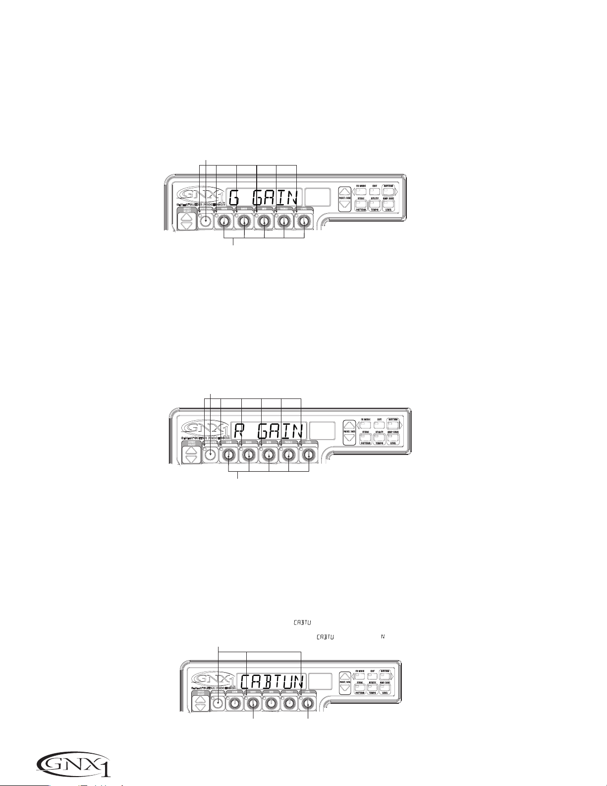
SECTION FOUR - TUTORIAL
Adjust the Green Channel Parameters
The Tweed amp that we selected for our Green Channel assignment will
initialize with factory default settings for the Gain, EQ, and Level
Parameters.These settings may not necessarily suit your personal taste
and require some fine tuning.To access these Green Channel Parameters,
press the Status button once.All horizontal LEDs will light green
indicating that all 5 knobs will now adjust the Green Channel Parameters.
Rotate the Number 1 Knob to adjust the Tweed Gain, Number 2
Knob to adjust the Tweed Bass, Number 3 Knob to adjust the Tweed
Mids,Number 4 Knob to adjust the Tweed Treble,and the Number 5
Knob to adjust the Tweed Level.
Appuyez sur Status, tous les témoins s'allument en vert
Nach Drücken der Status-Taste leuchten alle LEDs grün.
Les potentiomètres sont désormais affectés aux réglages
de gain, d'égalisation et de niveau du canal vert
Reglerfunktionen ändern sich, um Gain, EQ und Level des
Grünen Kanals einzustellen.
SECCIÓN CUATRO - TUTORIAL
Ajuste de los parámetros del canal verde
El amplificador Tweed elegido como asignación para nuestro canal verde se
inicializará con los ajustes de fábrica para los parámetros de ganancia,
ecualización y nivel.Estos valores puede que no coincidan con sus gustos
personales y quizá deba retocarlos.Para acceder a estos parámetros delc
anal verde,pulse una vez el botón Status.Todos los pilotos horizontales
se iluminarán para indicar que los cinco mandos ajustan ahora los
parámetros del canal verde.Gire el mando 1 para ajustar la ganancia del
Tweed, el mando 2 para ajustar los bajos, el mando 3 para ajustar el
rango de los medios,el mando 4 para ajustar los agudos del Tweed y el
mando número 5 para ajustar el nivel.
Adjust the Red Channel Parameters
Like the Tweed amp in the Green Channel,the Rectified amp in the Red
Channel may need to be tweaked to suit your personal taste. To access
these Red Channel Parameters,press the Status button again.All
horizontal LEDs will light red indicating that all 5 knobs will now adjust the
Red Channel Parameters.Rotate the Number 1 Knob to adjust the
Rectified Gain,Number 2 Knob to adjust the Rectified Bass, Number 3
Knob to adjust the Rectified Mids, Number 4 Knob to adjust the
Rectified T reble,and the Number 5 Knob to adjust the Rectified Level.
Appuyez une nouvelle fois sur Status, les témoins s'allument en rouge
Nach nochmaligem Drücken der Status-Taste leuchten alle LEDs rot.
Les potentiomètres sont désormais affectés au réglage
du gain, d'égalisation et de niveau du canal rouge
Reglerfunktionen ändern sich, um Gain, EQ und Level des
Roten Kanals einzustellen.
Tune the Cabinets (optional)
We may also want to adjust the resonance for the American 2x12 and the
British 4x12 Cabinets.To access the Cabinet tuning for both Red and
Green Channels,press and hold the Status button until the Display reads
CABTUN (Cabinet Tuning). Release the Status button and rotate the
Number 2 Knob to adjust the tuning for the Green Cabinet (GT º0)
and the Number 5 Knob to adjust the tuning for the Red Cabinet (RT
º0).Once the tuning of both Cabinets have been adjusted,press the
Status button again to return to the Performance mode.
Ajuste de los parámetros del canal rojo
Al igual que el amplificador Tweed en el canal verde,puede que también
tenga que retocar los parámetros del amplificador Rectified del canal rojo
para adaptarlos a sus gustos.Para acceder a estos parámetros del canal
rojo, pulse de nuevo el botón Status.Todos los LEDs horizontales se iluminarán ahora en rojo para indicar que los 5 mandos ajustan ahora los
parámetros del canal rojo.Gire el mando 1 para ajustar la ganancia del
Rectified,el mando 2 para ajustar los bajos, el mando 3 para ajustar el
rango de los medios,el mando 4 para ajustar los agudos y el mando
número 5 para ajustar el nivel.
Afinación de los recintos acústicos (opcional)
También puede que quiera ajustar la resonancia de los recintos acústicos
American 2x12 y British 4x12.Para acceder a la afinación de recinto para
ambos canales,mantenga pulsado el botón Status hasta que aparezca
CABTUN (afinación de recinto). Deje de pulsar el botón Status y gire el
mando 2 para ajustar la afinación del recinto acústico del canal verde (GT
º0) y el mando 5 para ajustar el del canal rojo (RT º0).Una vez que
haya ajustado la afinación de los recintos de ambos canales,pulse de nuevo
el botón Status para volver al modo de ejecución.
26
Maintenez Statut enfoncée jusqu'à ce que s'affiche à l'écran,
le témoin du potentiomètre 2 s'allume en vert et celui du potentiomètre 5 en rouge
Status-Taste gedrückt halten, bis auf dem Display angezeigt wird und die
Regler 2-LED grün und die Regler 5-LED rot leuchtet.
Accordez l'enceinte verte avec le potentiomètre 2
Green Cabinet-Stimmung mit Regler 2 einstellen
Accordez l'enceinte rouge avec le potentiomètre 5
Red Cabinet-Stimmung mit Regler 5 einstellen
Page 31

SECTION FOUR - TUTORIAL SECCIÓN CUATRO - TUTORIAL
k
Warp the Green and Red Channels Together
When we have the Amps and Cabinets in our Green and Red Channels
dialed in to suit our taste, we can Warp them together to create our new
HyperModel™.Make sure your GNX1 is in yellow mode (indicated by the
Status LED lighting yellow).If it is not in yellow mode,press the Status or
Exit button until yellow mode has been accessed.Then rotate the
Number 3 (Warp) Knob to achieve the desired blend of the Amps and
Cabinets in our Green and Red Channels.
Save the HyperModel™
Now that we have designed our own Amp/Cabinet HyperModel™,we
need to save our creation to one of the 16 User HyperModel™ locations.
This will enable us to use it in Presets.Press the Amp Save button once.
The Display will read NEWAMP (New Amp) and the first letter (N) will be
flashing.This is asking us to name the new HyperModel™. For the sake of
this example, let’s name the HyperModel™ “Rectwd” (Rectified Tweed).
Press the Data Up/Down buttons to select R as the first letter.Then
press the Rhythm button to select the next character in the Display.This
character should already be an E because we started out with the name
“NEWAMP.” If it is not an E,press the Data Up/Down buttons to select
E as the character. Continue to use the Rhythm button to select the next
character location in the Display,and the Data Up/Down buttons to
select the alphabetic characters until the Display reads RECTWD.
3 Appuyez sur Rhythm pour passer au caractère suivant
3 Rhythm-T aste drücken, um nächstes Zeichen zu wählen.
Enlace de los canales rojo y verde
Cuando ya haya ajustado a su gusto los amplificadores y recintos del canal
verde y el rojo,puede enlazarlos juntos para crear un nuevo
HyperModel™. Asegúrese de que su GNX1 esté en el modo amarillo
(indicado por el LED de Status iluminado en amarillo).Si no está en ese
modo,pulse el botón Status o Exit hasta que acceda al modo amarillo.
Gire después el mando 3 (Warp) para conseguir la mezcla de amplificadores y recintos que quiera entre ambos canales.
Almacenamiento del HyperModel™
Ahora que hemos diseñado nuestro propio HyperModel™ de amplificador /
recinto,tenemos que almacenar nuestra creación en una de las 16 posiciones
de HyperModel™ de usuario.Esto nos permitirá usarlo luego en Presets.
Pulse una vez el botón Amp Save.En la pantalla aparecerá NEWAMP (Nuevo
amplificador) y parpadeará la primera letra del nombre (N).Esto le estará
pidiendo que elija la primera letra para el nombre de su HyperModel™.Para
este ejemplo,vamos a poner a nuestro HyperModel™ el nombre “Rectwd”
(Rectified Tweed).Pulse los botones Data arriba/abajo para elegir R como
primera letra.Pulse después el botón Rhythm para elegir el siguiente carácter de la pantalla.Este caracter debería ser ya una E dado que ya estaba con
el nombre “NEWAMP.” Si no fuese una E,pulse los botones Data
arriba/abajo para elegir una E como carácter.Continúe usando el botón
Rhythm para elegir la siguiente posición de carácter de la pantalla, y los
botones Data arriba/abajo para elegir los caracteres específicos,hasta que
en la pantalla quede RECTWD.
2 Sélectionnez les caractères à l'aide des boutons Data
2 Blinkendes mit den Data-Tasten in ein ändern.
Then press the Amp Save button again.This will take us to the second
step of saving a HyperModel™,which is choosing one of the 9 User
HyperModel™ locations.The alpha-numeric Display should read EMPTY
(Empty) and the red numeric Display should read U1 because this is the
first HyperModel™ stored to your GNX1.Press the Amp Save button
again to store this new creation to this Amp location.The Display will
briefly read AMPSVD (Amp Saved) and then return to showing the name
of the currently selected Preset.
Sélectionnez un emplacement Amp
utilisateur à l'aide des touches DATA
User Amp-Position mit den Data-Tasten wählen
Assign Models to the Preset Channels
In the previous steps,we assigned a Tweed to the Green Channel and a
Rectified Model to the Red Channel.Then we Warped the two together to
create our HyperModel™.This HyperModel™ is now saved as an amp type that
we named Rectwd, but it is not currently a part of our Preset.In this example
Preset,we were going to have the ability to toggle between an acoustic guitar
simulation and our new HyperModel™.To do this we need to assign the
acoustic model to the Green Channel and our new Rectwd to the Red Channel
of our Preset.The LED next to the Status button should currently be yellow.If
it is not,press the Exit button. Now rotate the Number 1 Knob until the
Display reads ACOUST.This is the Green Channel Model for the Preset.Now
rotate the Number 4 Knob until the Display reads RECTWD (our new
HyperModel™).This is the Red Channel Model for the Preset.We will now be
able to toggle between these two sounds using the Amp Footswitch.
1 Appuyez sur Amp Save
1 Amp Save drücken
Pulse de nuevo el botón Amp Save.Esto hará que vaya a la siguiente fase
del almacenamiento del HyperModel™,en la que elegirá una de las 9 posiciones de HyperModel™ de usuario.En la pantalla alfanumérica debería
aparecer EMPTY (vacío) y en la pantalla numérica roja debería ver U1
dado que ese es el primer HyperModel™ almacenado en su GNX1.Pulse
de nuevo el botón Amp Save para guardar su nueva creación en una
posición de amplificador. En la pantalla aparecerá brevemente AMPSVD
(Amplificador guardado) y después volverá a aparecer el nombre del preset activo en ese momento.
Appuyez sur Amp Save
Nochmals Amp Save drüc
Asignación de modelos a los Presets de canal
En los pasos anteriores hemos asignado un Tweed al canal verde y un modelo
Rectified al canal rojo.Después hemos enlazado los dos juntos para crear nuestro propio HyperModel™.Este HyperModel™ ha sido ahora guardado como
un tipo al que hemos llamado Rectwd,si bien todavía no es parte de nuestro
Preset.En este Preset de ejemplo,vamos a hacer que podamos cambiar entre
una simulación de guitarra acústica y nuestro nuevo HyperModel™. Para hacer
esto tenemos que asignar un modelo acústico al canal verde y nuestro nuevo
Rectwd al canal rojo de nuestro Preset.El piloto que está al lado del botón
Status debería estar iluminado ahora en amarillo.Si no lo está,pulse el botón
Exit.Gire ahora el mando 1 hasta que en la pantalla vea ACOUST.Esto es el
modelo del canal verde para este Preset.Gire ahora el mando 4 hasta que en
la pantalla aparezca RECTWD (nuestro nuevo HyperModel™).Este es el modelo
del canal rojo para el Preset.A partir de ahora podemos cambiar entre estos
dos sonidos usando el pedal de disparo Amp.
27
Page 32

SECTION FOUR - TUTORIAL
Edit the Preset
The next step to creating our example Preset is to enter the Preset Edit mode.
To do this, press the Effect Select Down button once. At this point the
Matrix LED in the Wah-Pickup row should light.The Display will briefly show
EDIT and then cycle between showing the status of the Wah and Pickup
simulator Effects.If the Display shows that the Wah is on (WAH ON),press the
Status button once to turn it off (since our example is not using a Wah).
Appuyez sur le bouton Effect Select
du bas, le témoin de la rangée
Wah-Pickup s'allume
Effect Select Down-Taste drücken,
damit die LED in der Wah-Pickup
Effect-Zeile leuchtet.
Appuyez si nécessaire sur Status pour désactiver l'effet Wah
Nötigenfalls Status-Taste drücken, um Wah-Effekt auszuschalten
SECCIÓN CUATRO - TUTORIAL
Edición del Preset
El siguiente paso en la creación de nuestro Preset de ejemplo es entrar en el
modo de edición de Preset.Para hacer esto,pulse una vez el botón Effect
Select abajo. En este punto, el piloto de la fila Wah-Pastilla de la matriz
debería iluminarse. En la pantalla debería aparecer brevemente EDIT y después
ir mostrando el estado de los efectos de Wah y simulador de pastilla.Si la pantalla le muestra que el Wah está activado (WAH ON), pulse una vez el botón
Status para desactivarlo (dado que en nuestro ejemplo no usamos el Wah).
Select the Pickup Type
In our example Preset we were assuming that we were using a single coil
pickup,but wanted it to sound like a double coil humbucker.With the WahPickup LED lit,rotate the Number 4 Knob until the Display shows SC>HB.
This means that a single coil will sound like a Humbucker.
Turn the Compressor Off
Next,we didn’t want to use compression in our Preset so, we need to turn the
compressor off. Press the Effect Select Down button again. The LED on the
Compression row will light and the Display will show the current status of the
Compressor.If the Compressor is on,press the Status button until the Display
shows CMPOFF.The Compressor will then be disengaged.
Turn the Whammy™/IPS Off
We didn’t want to use any Whammy™ or IPS effects in this Preset.Press the
Effect Select Down button again and the LED on the Whammy/IPS row will
light.If the Display indicates that either one of these effects is active,press the
Status button until the Display reads IPSOFF (IPS Off).
Elección del tipo de pastilla
En nuestro Preset de ejemplo hemos asumido que usábamos una pastilla de
bobinado simple, pero que queríamos que sonase como una humbucker de
doble bobinado.Con el piloto Wah-Pickup encendido,gire el mando 4 hasta
que en la pantalla aparezca SC>HB.Esto implica que una pastilla sencilla sonará
ahora como una pastilla Humbucker.
Sélectionnez à l'aide du
potentiomètre 4.
Number 4-Regler drehen, bis auf
dem Display
Desactivación del compresor
Después,hemos dicho que en nuestro Preset no queremos usar compresión,
por lo que tenemos que desactivar este efecto.Pulse de nuevo el botón Effect
Select abajo.El piloto de la fila Compression se encenderá y en la pantalla
verá el estado actual del compresor. Si el compresor está activo,pulse el botón
Status hasta que en pantalla vea CMPOFF. En ese momento el compresor
quedará desactivado.
Desactivación del Whammy™/IPS
En nuestro Preset tampoco queríamos usar ningún efecto Whammy™ o IPS.
Pulse nuevamente el botón Effect Select abajo hasta hacer que se encienda el
piloto de la fila Whammy/IPS. Si la pantalla le indica que alguno de estos efectos
están activos (o ambos),pulse el botón Status hasta que en la pantalla vea
IPSOFF (IPS Off).
angezeigt wird.
28
Page 33

SECTION FOUR - TUTORIAL SECCIÓN CUATRO - TUTORIAL
Adjust the EQ
The EQ for both the Acoustic Model in the Green channel and our Rectwd
HyperModel™ in the Red channel can be adjusted individually. To do so, press
the Effect Select Down button again and the LED on the Equalizer row will
light.The GNX1 will default to the EQ adjustments for the Red Channel and
the Display will briefly read EQ RED (EQ Red). Rotate the Number 1 Knob
to adjust the Red Channels Bass enhancement,the Number 2 Knob to select
the center frequency for the Mid-range,the Number 3 Knob to adjust the
Mid-range enhancement,the Number 4 Knob to select the center frequency
for the Treble, and the Number 5 Knob to adjust the Treble enhancement.
Press the Status button or Amp Footswitch to select the Green Channel’s
EQ adjustments.The Display will briefly read EQ GRN (EQ Green) and the
same knobs will adjust the same EQ Parameters for the Green Channel.
Sélectionnez l'égaliseur du canal vert ou
du canal rouge à l'aide du bouton Status
Status-Taste wählt EQ für Grünen oder Roten Kanal
Appuyez une nouvelle fois sur
la flèche Effect Select du bas
pour que le témoin EQ s'allume
Nochmals Effect Select Down
drücken, bis EQ LED leuchtet
Réglage
Fréquence
graves
Regelt die
Bässe
médiums
Frequenz
Ajuste del EQ
Puede ajustar de forma individual la ecualización tanto para el modelo acústico
del canal verde como para nuestro HyperModel™ Rectwd del canal rojo.Para
hacerlo,pulse de nuevo el botón Effect Select abajo para hacer que se ilumine el LED de la fila Equalizer. El GNX1 por defecto va a los ajustes de EQ del
canal rojo y la pantalla le muestra brevemente EQ RED (EQ rojo). Gire el
mando 1 para ajustar el realce de graves del canal rojo,el mando 2 para ele-
gir la frecuencia central para el rango medio,el mando 3 para ajustar el realce
de los medios,el mando 4 para elegir la frecuencia central de los agudos y el
mando número 5 para ajustar el realce de agudos.Pulse el botón Status o el
pedal Amp para elegir los ajustes de ecualización del canal verde.En la pantalla
aparecerá brevemente EQ GRN (EQ verde) y los mismos mandos de antes ajustarán los mismos parámetros de ecualización para el canal verde.
Réglage
Mitte-
médiums
Regelt die
Mitten
Fréquence
Frequenz
aiguë
Treble-
Réglage
aigus
Regelt die
Höhen
Adjust the Noise Gate
For our example, we wanted our Noise Gate to open quickly with a relatively
weak signal.This type of gate would use the Silencer™ with a low Threshold
and short Attack Time . Press the Amp Footswitch again to select the Red
Amp Channel.Now press the Effect Select Down button and the LED in the
Noise Gate row will light.If the Display indicates that the Noise Gate is off
(GATOFF),press the Status button until the Display reads GAT ON (Gate On).
Rotate the Number 1 Knob until the Display reads SILNCR (Silencer) as the
type of gate. Rotate the Number 2 Knob to set the Threshold to a value of 20
(this may need further adjustment depending upon your guitar).Rotate the
Number 3 Knob to set the Attack Time value to 0 (fast attack).
Activez le Noise Gate à l'aide du bouton Status
Gate mit Status-Taste einschalten
Appuyez sur la flèche Effect Select
du bas pour allumer le témoin Noise Gate
Nochmals Effect Select Down drücken,
bis Noise Gate LED leuchtet
Ajuste de la puerta de ruidos
Para nuestro ejemplo,queríamos que la puerta de ruidos se abriese rápidamente con señales relativamente débiles.Este tipo de puerta debería usar el
tipo Silencer™ con un umbral bajo y un tiempo de ataque rápido.Pulse de
nuevo el Pedal Amp para elegir el canal de amplificación rojo.Pulse después el
botón Effect Select abajo hasta que se ilumine el piloto de la fila de puerta de
ruidos de la matriz.Si en la pantalla se indica que la puerta de ruidos está desactivada (GATOFF),pulse el botón Status hasta que en la pantalla aparezca GAT
ON (puerta activada). Gire el mando 1 hasta que en la pantalla vea SILNCR
(Silencer) como tipo de puerta. Gire el mando 2 para ajustar el umbral a un
valor de 20 (puede que tenga que ajustarlo a otro valor dependiendo de su guitarra).Gire el mando 3 para ajustar el valor de tiempo de ataque a 0 (ataque
rápido).
Sélectionnez le Noise
Gate de type Silencer
Silencer als Gate-
Typ wählen
Réglez le seuil
sur 20
Threshold-Wert auf
20 setzen
Réglez l'attaque
sur 0
Attack-Wert auf
0 setzen
29
Page 34

SECTION FOUR - TUTORIAL
Select and Adjust the Chorus
Next we wanted to thicken up the sound in our Preset by adding a subtle
Chorus effect.Press the Effect Select Down button again and the LED in the
Chorus/Mod row will light.If the Display indicates that this module is off
(EFFOFF),press the Status button until the Display reads EFF ON (Effect
On).Then rotate the Number 1 Knob until the Display shows CHORUS
(Chorus) as the effect type. Rotate the Number 2 Knob to set the Chorus
Speed to a value of 5.Rotate the Number 3 Knob to set the Chorus Depth
to a value of 30. Rotate the Number 5 Knob to set the Chorus Level to a
value of 50.
Activer le module d'effet à l'aide du bouton Status
Effekt-Modul mit Status-Taste einschalten
Appuyez sur la flèche
Effect Module du bas pour
que le témoin Chorus/Mod s'allume
Nochmals Effect Select Down-Taste
drücken, bis Chorus/Mod LED leuchtet
Sélectionnez Chorus comme
type de modulateur
Chorus als Mod Type wählen
Réglez la vitesse du
SECCIÓN CUATRO - TUTORIAL
Elección y ajuste del Chorus
Ahora queremos que el sonido de nuestro preset se fortalezca añadiendo un
sutil toque de efecto Chorus.Pulse una vez más el botón Effect Select abajo
hasta que se encienda el piloto de la fila Chorus/Mod.Si en pantalla aparece que
este módulo está desactivado (EFFOFF),pulse el botón Status hasta que vea
en pantalla EFF ON (Efecto activado). Gire después el mando 1 hasta que en
la pantalla aparezca CHORUS (Chorus) como tipo de efecto.Gire el mando 2
para ajustar la velocidad del Chorus a un valor de 5.Gire el mando 3 para
ajustar la profundidad del Chorus a un valor de 30.Gire el mando número 5
para ajustar el nivel del chorus a un valor de 50.
Réglez le niveau du
Chorus sur 50
Chorus Level
auf 50 setzen
Chorus sur 5
Chorus Speed
auf 5 setzen
Réglez la profondeur
du Chorus sur 30
Chorus Depth
auf 30 setzen
Turn the Delay Off
In our example Preset we wanted the Delay to be bypassed. Press the Effect
Select Down button again and the LED in the Delay row will light.If the
Display indicates that the Delay is on (DLY ON),press the Status button until
the Display reads DLYOFF (Delay Off).
Select and Adjust the Reverb
In our example Preset we also wanted a little bit of Hall Reverb to provide
some ambience. Press the Effect Select Down button again and the LED in
the Reverb row will light.If the Display indicates that the Reverb is off
(RVBOFF),press the Status button until the Display reads RVB ON (Reverb
On).Rotate the Number 1 Knob to select HALL (Hall) as the Reverb Type.
Rotate the Number 2 Knob to set the Reverb Predelay to a value of 2.Rotate
the Number 3 Knob to set the Reverb Decay to a value of 15.Rotate the
Number 4 Knob to set the Reverb Damping to a value of 40.Rotate the
Number 5 Knob to set the Reverb Level to a value of 30.
Appuyez sur Status pour activer la réverbération
Reverb mit Status-Taste einschalten
Appuyez sur la flèche
Effect Select du bas pour
que le témoin Reverb s'allume
Nochmals Effect Select Down-Taste
drücken, bis Reverb LED leuchtet
Desactivación del retardo
En nuestro Preset de ejemplo queríamos que el retardo quedase anulado.Pulse
de nuevo el botón Effect Select abajo para hacer que se encienda el LED de
la fila Delay.Si la pantalla le indica que el retardo está activado (DLY ON),pulse
el botón Status hasta que en pantalla vea DLYOFF (retardo desactivado).
Elección y ajuste de la Reverb
En nuestro Preset queremos tener un pequeño toque de reverb de salón para
dar algo de ambientación acústica.Pulse otra vez el botón Effect Select abajo
para hacer que se encienda el piloto de la fila Reverb.Si la pantalla le indica que
la reverb está desactivada (RVBOFF),pulse el botón Status hasta que vea en la
pantalla RVB ON (Reverb activada). Gire el mando 1 para elegir HALL (salón)
como tipo de reverb.Gire el mando 2 para ajustar el pre-retardo de la reverb
a un valor de 2.Gire el mando 3 para ajustar el decaimiento de la reverb a un
valor de 15.Gire el mando 4 para ajustar la amortiguación de la reverberación
a un valor de 40.Gire el mando número 5 para ajustar el nivel de la Reverb a
un valor de 30.
30
Sélectionnez
Hall
Hall wählen
Réglez PreDelay
sur 2
PreDelay-Wert
auf 2 setzen
Réglez Decay
sur 15
Decay-Wert
auf 15 setzen
Réglez Damping
sur 40
Damping-Wert
auf 40 setzen
Réglez le niveau de la
réverbération sur 30
Reverb Level
auf 30 setzen
Page 35

SECTION FOUR - TUTORIAL SECCIÓN CUATRO - TUTORIAL
Store the Preset
The last step that we need to do is to store our changes to a User Preset.If we
changed Presets or turned the GNX1 off without storing these settings,it
would forget what we had done and revert back to the original Preset.Press the
Store button once. The first letter in the Display begins to flash which is asking
us to rename the Preset.Since this is an example Preset, let’s name the Preset
exampl.Press the Data Up/Down buttons until the flashing character in the
Display is an E.Press the Rhythm button once and the second character
begins to flash.Use the Data Up/Down buttons again until the flashing
character is an X.Press the Rhythm button again to Select the third character
and change it to an A using the Data Up/Down buttons. Continue using the
Rhythm button to select the characters and the Data Up/Down buttons to
change the characters.
3 Déplacez-vous parmi les caractères
à l'aide des touches FX Mode et Rhythm
Zeichenpositionen mit FX Mode- und
3
Rhythm-Tasten wählen
Almacenamiento del Preset
El último paso que tenemos que hacer es guardar nuestros cambios en un
Preset de usuario.Si cambiamos a otro Preset o apagamos el GNX1 sin guardar
estos ajustes,perderíamos todo lo que habíamos hecho y volveríamos al preset
original.Pulse una vez el botón Store.La primera letra de la pantalla comenzará
a parpadear para indicarnos que le demos un nuevo nombre al Preset. Dado que
esto es un Preset de ejemplo,vamos a llamarle exampl. Pulse los botones
Data arriba/abajo hasta que el carácter que parpadea en la pantalla sea una E.
Pulse una vez el botón Rhythm para que comience a parpadear el segundo
carácter de la pantalla.Use de nuevo los botones Data arriba/abajo hasta que
el carácter parpadeante sea una X.Pulse nuevamente el botón Rhythm para
elegir el tercer carácter y cambiarlo a una A usando los botones Data
arriba/abajo.Continúe usando el botón Rhythm para elegir los caracteres y
los botones Data arriba/abajo para cambiar los caracteres.
1 Appuyez sur Store
1 Store drücken
2 Éditez les caractères
à l'aide des touches Data
2 Zeichen mit Data-Tasten ändern
Once the Display reads exampL,press the Store button again.Now the
numbers in the red numeric Display are flashing,which is asking where to store
this new Preset.Using the Data Up/Down buttons,select 48 as the
destination.Press the Store button one more time to execute the Store
function.
Congratulations! You have successfully created a Preset.
Una vez que en pantalla tenga el nombre exampL,pulse de nuevo el botón
Store.Ahora parpadearán los números de la pantalla numérica roja, lo que le
estará pidiendo que elija en qué lugar guardar su nuevo Preset.Usando los
botones Data arriba/abajo,elija 48 como destino.Pulse el botón Store una
vez más para ejecutar la función de almacenamiento.
Appuyez sur Store
Sélectionnez l'emplacement 48
à l'aide des touches Data
User Preset 48 mit den Data-Tasten wählen
Nochmals Store drücken
¡Felicidades! Acaba de crear un Preset con éxito.
31
Page 36

SECTION FIVE - OTHER FUNCTIONS
SECCIÓN CINCO - OTRAS FUNCIONES
Section Five - Other Functions
Expression Pedal
The Expression Pedal on the GNX1 can be assigned to control up to 3
Parameters in real time including the Volume,Whammy™,Ya Ya™,or just about
any other parameter.. When a parameter has been assigned to the Expression
Pedal,the minimum and maximum values the assigned Parameter will reach can
also be programmed.The GNX1’s Expression Pedal includes DigiTech’s exclusive
V-Switch. The V-Switch allows the Expression Pedal assignment to be switched
on the fly.Applying extra pressure to the toe of the Expression Pedal will engage
the V-Switch and the function of the Expression Pedal will switch between the
assigned parameter and Wah. The sensitivity or amount of pressure required to
engage the V-Switch can be adjusted to suit your personal taste (or weight of
your foot).See page 35 for the V-Switch Sensitivity adjustment procedure.
The procedure for assigning a parameter to the Expression Pedal is as follows:
1.Press the Effect Select button until the Exp Assign row has been selected.
2.Press the Status button until the Display reads EXPDL1 (Expression Pedal
Link 1),EXPDL2 (Expression Pedal Link 2), or EXPDL3 (Expression Pedal
Link 3),depending upon which assignment you wish to use or the number of
Parameters you intend to assign.The Display will alternate between showing
the Expression Pedal selection and the currently assigned Parameter.
3.Rotate the Number 1 Knob until the desired Parameter appears in the
Display.See the Expression Parameter Assignment List on page 33 for a
complete list of assignable Parameters.
4.Rotate the Number 2 Knob to select the minimum value the assigned
parameter will reach with the Expression Pedal in the toe up position (not
available when volume is the assigned parameter).
5.Rotate the Number 3 Knob to select the maximum value the assigned
parameter will reach with the Expression Pedal in the toe down position (not
available when volume is the assigned parameter).
6.Store your Expression Pedal assignment to your Preset. See page 17 for more
information on the storing procedure.
LFOs
The GNX1 includes two assignable low frequency oscillators (LFO1 and LFO2)
which can be assigned to any of the same parameters available for assignment to
the Expression Pedal.A low frequency oscillator will automatically vary the value
of the assigned parameter at a steady rate.A minimum and maximum value each
LFO will reach may be also be assigned.For instance: if the Amp Gain was
assigned to LFO1,and the minimum value was set at 1 and the maximum value
was set at 99,the GNX1 would automatically sweep the amount of distortion
from a clean sound to a distorted sound.Individual LFO speeds are also
available for assignment.In the previous example, the LFO speed would
determine the length of time it took the LFO to sweep from the clean to the
distorted sound. The procedure for assigning the LFOs in the GNX1 is as
follows:
1.Press the Effect Select button until the Exp Assign row has been selected.
2.Press the Status button to select whether you want to assign LFO1 (LFO1)
or LFO2 (LFO2).
3.Rotate the Number 1 Knob until the desired Parameter appears in the
Display.See the Expression Parameter Assignment list on page 33 for a
complete list of assignable Parameters.
4.Rotate the Number 2 Knob to select the minimum value the assigned
parameter will reach at the bottom turn around point for the LFO (not
available when volume is the assigned parameter).
5.Rotate the Number 3 Knob to select the maximum value the assigned
parameter will reach at the top turn around point for the LFO (not available
when volume is the assigned parameter).
6.Rotate the Number 4 Knob to select the speed at which the LFO will
oscillate from the minimum to the maximum values.LFO speed ranges from
.O5 HZ (.05 Hz) to 1ºO HZ (10.0 Hz).
7.Rotate the Number 5 Knob to select the waveform the LFO will oscillate
on.Your choices include:
TRINGL (Triangle) - a smooth rise and fall, but abrupt turn around in
oscillation.
SINE (Sine) - a smooth rise, fall, and turn around in oscillation.
SQUARE (Square) - an abrupt rise, fall, and turn around in oscillation.
8.Store your LFO assignment to your Preset.See page 17 for more information
on the storing procedure.
Sección Cinco - Otras Funciones
Pedal de expresión
El pedal de expresión del GNX1 puede ser asignado para controlar hasta 3
parámetros en tiempo real incluyendo el volumen, Whammy™,Ya Ya™,o casi
cualquier otro parámetro.Cuando un parámetro ha sido asignado al pedal de
expresión,también puede programar los valores mínimo y máximo que podrá
alcanzar dicho parámetro.El pedal de expresión del GNX1 incluye el exclusivo
V-Switch de DigiTech. Este interruptor V-Switch permite que la asignación del
pedal de expresión sea modificada sobre la marcha.Si aplica una presión extra
en la puntera del pedal se activará el V-Switch y la función del pedal de expresión cambiará entre el parámetro asignado y el Wah.La sensibilidad o cantidad
de presión necesaria para activar este V-Switch puede ser ajustada para adaptarla a sus gustos personales (o al peso de su pie).Vea en la página 35 el método
de ajuste de la sensibilidad del V-Switch.
El proceso de asignación de un parámetro al pedal de expresión es el siguiente:
1.Pulse el botón Effect Select hasta que haya elegido la fila Exp Assign.
2.Pulse el botón Status hasta que vea en pantalla EXPDL1 (enlace 1 del pedal de
expresión),EXPDL2 (enlace 2) o EXPDL3 (enlace 3 del pedal de expresión),
dependiendo de cual sea la asignación que quiera usar o el número de parámetros que quiera asignar.La pantalla irá cambiando entre la indicación de la selección del pedal de expresión y el parámetro asignado en ese momento.
3.Gire el mando 1 hasta que en la pantalla vea el parámetro que quiera.Vea en
la página 33 en listado de asignaciones de parámetro de expresión para tener
un listado completo de los parámetros asignables.
4.Gire el mando 2 para elegir el valor mínimo que alcanzará el parámetro asignado cuando el pedal de expresión esté en la posición de puntera arriba (esto
no está disponible cuando el parámetro asignado es el volumen).
5.Gire el mando 3 para elegir el valor máximo que alcanzará el parámetro
asignado cuando el pedal de expresión esté en la posición de puntera abajo
(esto no está disponible cuando el parámetro asignado es el volumen).
6. Almacene su asignación de pedal en su Preset.Vea en la página 17 más información acerca del proceso de almacenamiento.
LFOs
El GNX1 incluye dos osciladores de baja frecuencia asignables (LFO1 y LFO2)
que pueden ser asignados a cualquiera de los parámetros disponibles para su
asignación al pedal de expresión. Un oscilador de baja frecuencia hará que varíe
de forma automática el valor del parámetro asignado a una velocidad constante.
También puede asignar un valor mínimo y máximo que alcanzará cada uno de
los LFO.Por ejemplo: Si la ganancia del amplificador ha sido asignada al LFO1,y
el valor mínimo ha sido fijado en 1 con el máximo en 99,el GNX1 hará
automáticamente un barrido en la cantidad de distorsión desde un sonido
limpio a uno distorsionado.También puede asignar velocidades de LFO individuales.En el ejemplo anterior,la velocidad del LFO determinaría el tiempo que
tardaría el sonido limpio en convertirse en uno distorsionado.El proceso de asignación de los LFOs en el GNX1 es el siguiente:
1.Pulse el botón Effect Select hasta que haya elegido la fila Exp Assign.
2.Pulse el botón Status para elegir si quiere asignar el LFO1 (LFO1) o el
LFO2 (LFO2).
3.Gire el mando 1 hasta que en la pantalla aparezca el parámetro que quiera.
Vea en la página 33 en listado de asignaciones de parámetro de expresión
para tener un listado completo de los parámetros asignables.
4.Gire el mando 2 para elegir el valor mínimo que alcanzará el parámetro asignado en el punto de giro inferior del LFO (esto no está disponible cuando el
parámetro asignado es el volumen).
5.Gire el mando 3 para elegir el valor máximo que alcanzará el parámetro
asignado en el punto de giro superior del LFO (esto no está disponible cuando el parámetro asignado es el volumen).
6.Gire el mando 4 para elegir la velocidad de oscilación del LFO entre sus val-
ores mínimo y máximo.El rango de velocidades para el LFO va dese.O5 HZ
(.05 Hz) a 1ºO HZ (10.0 Hz).
7.Gire el mando número 5 para elegir la forma de onda con la que oscilará
el LFO.Sus opciones son:
TRINGL (Triangular) - un suave aumento y caida,pero con un giro algo brusco en las oscilaciones.
SINE (Sinusoidal) - una oscilación suave en todas sus fases.
SQUARE (Cuadrada) - una oscilación abrupta en todas sus fases.
8. Almacene su asignación de LFO en su Preset.Vea en la página 17 más información acerca del proceso de almacenamiento.
32
Page 37

SECTION FIVE - OTHER FUNCTIONS SECCIÓN CINCO - OTRAS FUNCIONES
Amp Footswitch
From the factory,the Amp Footswitch changes between the Green and the Red
Amp Channels.However, the GNX1 allows you to select the function of the
Amp Footswitch.The procedure for assigning the function of the Amp
Footswitch is as follows:
1.Press the Effect Select button until the Exp Assign row has been selected.
2.Press the Status button until the Display reads AMP FS (Amp Footswitch).
3.Rotate the Number 1 Knob to select the desired function of the Amp
Footswitch.Your choices include:
G-R - Switches between the Green and Red Amp Channels.
G-Y - Switches between the Green and Yellow (Warped) Channels.
R-Y - Switches between the Red and Yellow (Warped) Channels.
G-R-Y - Switches between the Green,Red, and Yellow (Warped) Channels.
4.Store your Amp Footswitch assignment to your Preset.See page 17 for more
information on the storing procedure.
Expression Parameter Assignment List
The following Parameters can be assigned to the any of the 3 Expression Pedal
links,LFO 1, or LFO 2.
NOLINK (No Link) - No Parameter is assigned
VOLPRE (Volume Pre) - Controls the Volume after the Amp Modeling but before the
Effects.
VOLPST (Volume Post) - Controls the Volume at the end of the Effects chain.
A WARP (Amp Warp) - Warps the Green and Red Amp Models.
C WARP (Cabinet Warp) - Warps the Green and Red Cabinet types.
WARP (Warp) - Warps the Green and Red Channels.
CMPATK (Compressor Attack) - Controls the Compressor’s Attack time.
CMPRTO (Compressor Ratio) - Controls the Compressor’s Ratio.
CMPTHR (Compressor Threshold) - Controls the Compressor’s Threshold.
CMPGAN (Compressor Gain) - Controls the Compressor’s Gain.
AMOUNT/SHIFT (Parameter 1) - Controls the interval for the IPS module.
WHMPDL (Whammy™ Parameter 2) - Controls the pitch bend when Whammy™ is
engaged.
SCALE (IPS Parameter 2) - Controls the scale when the IPS module is engaged.
KEY (IPS Parameter 3) - Controls the key type when the IPS module is engaged.
IPSMIX/IPSLVL (IPS Mix/Level) - Controls the wet/dry mix or Level for the IPS
AMPCHN (Amp Channel) - Switches Amp Channels.
G GAIN (Green Gain) - Controls the Amp Gain for the Green Channel.
G LEVL (Green Level) - Controls the Volume of the Green Channel.
R GAIN (Red Gain) - Controls the Amp Gain for the Red Channel.
R LEVL (Red Level) - Controls the Volume of the Red Channel.
GATTHR (Gate Threshold) - Controls the Noise Gate’s Threshold.
GATATK (Gate Attack) - Controls the Noise Gate’s Attack time.
PLKSNS (Gate Pluck) - Controls the Noise Gate’s Pluck Sensitivity.
Modulation Effects Parameters
module.
Effet actif
Chorus SPEED DEPTH PREDLY MODBAL MODLVL
Flanger SPEED DEPTH REGEN MODBAL MODMIX
Phaser SPEED DEPTH REGEN MODBAL MODMIX
Triggered Flanger SPEED SENSTV LFO ST MODMIX
Triggered Phaser SPEED SENSTV LFO ST MODMIX
Tremolo SPEED DEPTH
Panner SPEED DEPTH
Vibrato SPEED DEPTH
Rotary Speaker SPEED DEPTH DOPPLR XOVER MODBAL MODMIX
Auto Y a™ SPEED DEPTH RANGE MODBAL MODMIX
YaYa™ YA PDL DEPTH RANGE MODBAL MODMIX
SynthTalk ATTACK RELEAS VOX MODBAL SENSTV
Envelope Filter SENSTV RANGE MODBAL MODMIX
Detune AMOUNT MODBAL MODLVL
Pitch Shift SHIFT MODBAL MODLVL
Pedal de disparo Amp
Cuando la unidad sale de fábrica,el pedal de disparo Amp cambia entre los
canales de amplificación verde y rojo. No obstante, el GNX1 le permite elegir la
función que realizará este pedal de disparo Amp. El proceso para la asignación
de una función a este pedal es el siguiente:
1.Pulse el botón Effect Select hasta que quede seleccionada la fila Exp Assign.
2.Pulse el botón Status hasta que en la pantalla aparezca AMP FS (pedal de
disparo Amp).
3.Gire el mando 1 para elegir la función que quiera para el pedal de disparo
Amp.Sus posibles opciones son:
G-R - Cambio entre los canales de amplificación verde y rojo.
G-Y - Cambio entre los canales de amplificación verde y amarillo (enlazado).
R-Y - Cambio entre los canales de amplificación rojo y amarillo (enlazado).
G-R-Y - Cambio entre los canales de amplificación verde,rojo y amarillo (enlazado).
4.Guarde su asignación del pedal de disparo Amp en su Preset.Vea en la página
17 la información sobre este proceso de almacenamiento.
Lista de asignación de parámetros de expresión
Los parámetros siguientes pueden ser asignados a cualquiera de los 3 enlaces de
pedal de expresión,LFO 1 o LFO 2.
NOLINK (sin enlace) - No hay ningún parámetro asignado
VOLPRE (Volumen Pre) - Controla el volumen después del modelado de amplificador
pero antes de los efectos.
VOLPST (Volumen Post) - Controla el volumen al final de la cadena de efectos.
A WARP (Enlace Amp) - Enlaza los modelos de amplificación verde y rojo.
C WARP (Enlace recinto) - Enlaza los tipos de recinto acústico verde y rojo.
WARP (Enlace) - Enlaza los canales rojo y verde.
CMPATK (Ataque compresor) - Controla el tiempo de ataque del compresor.
CMPRTO (Ratio de compresor) - Controla el ratio o porcentaje del compresor.
CMPTHR (Umbral de compresor) - Controla el umbral del compresor.
CMPGAN (Ganancia de compresor) - Controla la ganancia del compresor.
AMOUNT/SHIFT (Parámetro1) - Controla el intervalo para el módulo IPS.
WHMPDL (Parámetro 2 Whammy™) - Controla la inflexión tonal que se produce cuando
el Whammy™ está activado.
SCALE (IPS Parámetro 2) - Controla la escala cuando está activo el módulo IPS.
KEY (IPS Parámetro 3) - Controla el tipo de clave cuando está activo el módulo IPS.
IPSMIX/IPSLVL (IPS Mezcla/Nivel) - Controla la mezcla seco/húmedo o el nivel para
el módulo IPS.
AMPCHN (Canal de amplificación) - Cambia entre los canales de amplificación.
G GAIN (Ganancia verde) - Controla la ganancia de amplificación para el canal verde.
G LEVL (Nivel verde) - Controla el volumen para el canal verde.
R GAIN (Ganancia rojo) - Controla la ganancia de amplificación para el canal rojo.
R LEVL (Nivel rojo) - Controla el volumen para el canal rojo.
GATTHR (Umbral puer ta) - Controla el umbral de la puerta de ruidos.
GATATK (Ataque de puer ta) - Controla el tiempo de ataque de la puerta de ruidos.
PLKSNS (Pluck de puer ta) - Controla la sensibilidad Pluck de la puerta de ruidos.
Parámetros de efectos de modulación
DLYFBK (Delay Feedback) - Controls the amount of Delay Feedback.
DUKTHR (Delay Threshold) - Controls the Ducker Threshold for the Delay.
DUkATN (Ducker Attenuation) - Controls the attenuation level applied to the Delay
signal when the Ducker Threshold is exceeded.
DLYLVL (Delay Level) - Controls the Mix Level of the selected Delay Type.
DLYBAL (Delay Balance) - Controls the left/right balance of the selected Delay Type.
RVBPRE (Reverb Predelay) - Controls the Reverbs Predelay time.
RVBDCY (Reverb Decay) - Controls the Reverbs Decay time.
RVBLVL (Reverb Level) - Controls the Reverbs Mix Level.
RVBBAL (Reverb Balance) - Controls the left/right balance of the selected Reverb Type.
LF1SPD (LFO 1 Speed) - Controls the modulation speed of Expression LFO 1.
LF2SPD (LFO 2 Speed) - Controls the modulation speed of Expression LFO 2.
DLYFBK (Realiment.retardo) - Controla la cantidad de realimentación del retardo.
DUKTHR (Umbral retardo) - Controla el umbral Ducker para el retardo.
DUkATN (Atenuación Ducker) - Controla el nivel de atenuación que se aplica a la señal
de retardo cuando es sobrepasado el umbral del Ducker.
DLYLVL (Nivel retardo) - Controla el nivel de mezcla para el tipo de retardo elegido.
DLYBAL (Balance de retardo) - Balance izda/drcha del tipo de retardo elegido.
RVBPRE (Pre-retardo de reverb) - Controla el tiempo de pre-retardo de las reverbs.
RVBDCY (Decaimiento Reverb) - Controla el tiempo de decaimiento de las reverbs.
RVBLVL (Nivel reverb) - Controla el nivel de mezcla de las reverbs.
RVBBAL (Balance reverb) - Balance izda/drcha del tipo de reverb elegido.
LF1SPD (velocidad LFO 1) - Controla la velocidad de modulación del LFO 1.
LF2SPD (velocidad LFO 2) - Controla la velocidad de modulación del LFO 2.
33
Page 38

SECTION FIVE - OTHER FUNCTIONS
Utilities
The Utility section contains all of the menus for assigning global functions to the
GNX1.Global functions affect the GNX1 in its entirety rather than on a per
Preset basis.The Utility menus include: Mono/Stereo Output,Target System
Setup,Volume Pedal Update, V-Switch Sensitivity,Pedal Calibration,Bank Naming,
MIDI Channel,MIDI Sysex Dumps,Amp Dumps, MIDI Mapping, MIDI Merge, and
Factory Reset. The Utility section is entered by pressing the Utility button at
which time the Utility button will light.Once in the Utility menu, the Rhythm
button selects the next menu (scrolls to the right),and the FX Mode button
selects the previous menu (scrolls to the left).Each of these Utility menus is
described in more detail in the following pages.
Mono/Stereo Output
The GNX1 needs to be told whether you wish to use it in a stereo or mono
mode. In Stereo mode, the GNX1 will produce a wide stereo image when
the Right and Left Outputs are connected to two different amplifiers.In
Mono mode, the same signal will appear at the Left and Right Outputs.The
procedure for selecting the output mode in the GNX1 is as follows:
1.Press the Utility button once.The LED in the Utility button will light
indicating you are in the Utility section.
2.Using the FX Mode or Rhythm buttons,scroll to the left or right until
the display shows either STEREO,or MONO as the active output mode.
3.Use the Data Up/Down buttons to select the desired output mode.
4.Press the Exit button to return to the GNX1 Presets.
Target System Setup
The GNX1 can be connected to any type of amplification system.However,
the signal requirements will change depending upon the type of amplification
used.The Target System Setup is intended to optimize the GNX1 for the
type of amplification system it will be used with.The procedure for selecting
the desired Target System is as follows:
1.Press the Utility button once.The LED in the Utility button will light
indicating you are in the Utility section.
2.Using the FX Mode or Rhythm button,scroll to the left or right until
the display shows one of the following listings of Target Systems:
SECCIÓN CINCO - OTRAS FUNCIONES
Utilidades
La sección de utilidades contiene todos los menús relacionados con la asignación
de funciones globales del GNX1.Las funciones globales afectan al GNX1 como
unidad en lugar de a cada Preset concreto.Los menús de utilidades incluyen:
Salida Mono/Stereo,Configuración del sistema de destino,Actualización del pedal
de volumen,Sensibilidad del V-Switch,Calibración del pedal, Nombrado de banco,
Canal MIDI,Volcados Sysex MIDI,Volcados de amplificadores,mapas MIDI,mezcla
MIDI y reinicialización a valores de fábrica.Para acceder a la función de utilidades
debe pulsar el botón Utility,tras lo cual se iluminará su piloto.Una vez que esté
en el menú de utilidades,el botón Rhythm elegirá el menú siguiente (desplazamiento a la derecha),mientras que el botón FX Mode elegirá el menú anterior
(desplazamiento a la izquierda).En las páginas siguientes le describiremos en
detalle cada uno de estos menús de utilidades.
Salida Mono/Stereo
Debe indicarle al GNX1 si quiere usarlo en un modo mono o stereo.En el
modo stereo,el GNX1 producirá una amplia imagen stereo cuando las salidas
izquierda y derecha estén conectadas a dos amplificadores distintos.En el
modo Mono,aparecerá la misma señal en las salidas izquierda y derecha.El
proceso para elegir el modo de salida del GNX1 es el siguiente:
1.Pulse una vez el botón Utility.El LED de este botón se encenderá para
indicarle que está en la sección de utilidades.
2.Usando los botones FX Mode o Rhythm, desplácese a la izquierda o a la
derecha hasta que en la pantalla vea STEREO o MONO como el modo de
salida activo.
3.Use los botones Data arriba/abajo para elegir el modo de salida que
quiera.
4.Pulse el botón Exit para volver a los Presets del GNX1.
Configuración del sistema de destino
Puede conectar el GNX1 a cualquier tipo de sistema de amplificación.Sin
embargo,los requisitos de la señal variarán dependiendo del tipo de amplificación que use. Este menú ha sido diseñado para optimizar el GNX1 para el
tipo de sistema de amplificación con el que lo vaya a usar. El proceso de
selección del sistema de destino que quiera es el siguiente:
1.Pulse una vez el botón Utility.El LED de este botón se encenderá para
indicarle que está en la sección de utilidades.
2.Usando los botones FX Mode o Rhythm, desplácese a la izquierda o a la
derecha hasta que la pantalla le muestre uno de los sistemas siguientes:
DIRECT (For direct to console
applications)
IN1X12 (Instrument input of a
1x12 combo amp)
FX1X12 (Input into the effect
return of a 1x12 combo)
IN2X12 (Instrument input of a
3.Press the Data Up/Down buttons to select the type of amplification
system (from the preceding list) to be used.
4.Press the Exit button to return to the GNX1 Presets.
Volume Pedal Update
The GNX1 provides the option of selecting the Expression Pedal’s position
to be updated after changing Presets when it is linked to the Volume
Parameter. This feature allows you to change Presets and retain the same
volume level from the previous Preset if the Expression Pedal is assigned to
control volume on both Presets.If this feature is disabled, new Presets will
initialize at the volume level value stored to the Preset. The procedure for
enabling or disabling the Volume Pedal Update is as follows:
1.Press the Utility button once. The LED in the Utility button will light
indicating you are in the Utility section.
2.Using the FX Mode or Rhythm button, scroll to the left or right until
the Display shows vOLUPD (Volume Pedal Update).
3.Press the Data Up/Down to select On (enabled), or OF (disabled).
4.Press the Exit button to return to the GNX1 Presets.
2x12 combo amp)
FX2X12 (Input into the effect
return of a 2x12 combo)
IN4X12 (Instrument input of a
4x12 combo amp)
FX4X12 (Input into the effect
return of a 4x12 combo)
DIRECT (para aplicaciones directas
a mesa de mezclas)
IN1X12 (entrada de instrumento
de un amplificador combo 1x12)
FX1X12 (entrada al retorno de
efectos de un combo 1x12)
IN2X12 (entrada de instrumento
3.Pulse los botones Data arriba/abajo para elegir el tipo de sistema de
amplificación (de entre los de la lista anterior) que vaya a usar.
4.Pulse el botón Exit para volver a los Presets del GNX1.
Actualización del pedal de volumen
El GNX1 le da la opción de elegir la posición del pedal de expresión a ser
actualizada tras el cambio de presets cuando está enlazada con el parámetro
de volumen.Esta función le permite cambiar los presets y mantener el mismo
nivel de volumen del preset anterior si el pedal de expresión está asignado al
control del volumen en ambos presets.Si esta función es desactivada, cada
nuevo preset hará que el pedal se inicialice al valor de nivel de volumen almacenado con el preset concreto.El proceso para la activación o desactivación
de la actualización del pedal de volumen es el siguiente:
1.Pulse una vez el botón Utility.El LED de este botón se encenderá para
indicarle que está en la sección de utilidades.
2.Usando los botones FX Mode o Rhythm, desplácese a la izquierda o a la
derecha hasta que la pantalla le muestre vOLUPD (actualización de pedal
de volumen).
3.Pulse Data arriba/abajo para elegir On (activado) u OF (desactivado).
4.Pulse el botón Exit para volver a los Presets del GNX1.
de un combo 2x12)
FX2X12 (entrada al retorno de
efectos de un combo 2x12)
IN4X12 (entrada de instrumento
de un amplificador combo 4x12)
FX4X12 (entrada al retorno de
efectos de un combo 4x12)
34
Page 39

SECTION FIVE - OTHER FUNCTIONS SECCIÓN CINCO - OTRAS FUNCIONES
V-Switch Threshold
Applying extra pressure on the toe of the Expression Pedal engages a feature
we call the V-Switch. The V-Switch is used to alternate between the
Expression Pedal controlling the assigned Parameter(s),and acting as a Wah
Pedal.The sensitivity of the V-Switch can be tailored to engage with the
amount of pressure you wish to use.
The following steps outline the procedure for adjusting the V-Switch
threshold:
1.Press the Utility button once.The LED in the Utility button will light
indicating you are in the Utility section.
2.Using the FX Mode or Rhythm button, scroll to the left or right until
the Display shows vSWICH (V-Switch).
3.Press the Data Up/Down to select the threshold setting you desire.
Ranges from 1 to 99 (with 99 requiring more pressure to engage).The
sensitivity may be auditioned while making adjustments.The Display will
read either WAH ON,or WAHOFF (depending on the status of the Wah) as
the V-Switch engages and disengages.
4.Press the Exit button to return to the GNX1 Presets.
Expression Pedal Calibration
The Expression Pedal on the GNX1 needs to be recalibrated for use after a
factory reset has been performed.This calibration procedure is automatically
entered after a factory reset procedure.In the event the Pedal’s calibration
fails,or if the Pedal does not function properly,it can be re-calibrated using
the Pedal Calibration menu.The procedure for Calibrating the Expression
Pedal is as follows:
1.Press the Utility button once.The LED in the Utility button will light
indicating you are in the Utility section.
2.Using the FX Mode or Rhythm button, scroll to the left or right until
the alpha-numeric Display shows
PDLCAL (Pedal Calibration).
3.Press the blinking Store button once to enter the Pedal Calibration Menu.
The alpha-numeric Display reads
TOE DN (Toe Down).
4.Rock the Expression Pedal all the way forward to the toe down position
and press the blinking number 2 Footswitch.The Display changes to read
TOE UP (toe up).
5.Rock the Expression Pedal all the way back to the toe up position and
press the blinking number 3 Footswitch.The Display will show VSWTCH
and allow you to adjust the V-Switch threshold.
6.Rock the Expression Pedal forward and apply the desired V-Switch pressure
to the toe of the pedal.If further adjustment to the threshold is required,
use the Data Up/Down buttons to select the desired threshold.
Note:If the Display shows ERROR,an error has occurred and steps 2
through 5 should be repeated.
7.Press the Exit button to return to the GNX1 Presets.
Umbral del V-Switch
La aplicación de una presión extra en la puntera del pedal de expresión hace
que se active una función a la que llamamos V-Switch.Este V-Switch se usa
para ir cambiando alternativamente entre el control del pedal de expresión
del parámetro(s) asignado,y el que actúe como un pedal Wah.La sensibilidad
de este V-Switch puede ser personalizada para que se active con la cantidad
de presión que quiera usar.
Los pasos siguientes le describen el procedimiento de ajuste del umbral de
este V -Switch:
1.Pulse una vez el botón Utility.El LED de este botón se encenderá para
indicarle que está en la sección de utilidades.
2.Usando los botones FX Mode o Rhythm, desplácese a la izquierda o a la
derecha hasta que en la pantalla aparezca vSWICH (V-Switch).
3.Pulse los botones Data arriba/abajo para elegir el valor de umbral que
quiera.El rango va de 1 a 99 (requiriendo el valor 99 una mayor presión
para la activación).Puede ir haciendo pruebas de estos ajustes mientras los
realiza. En la pantalla aparecerá WAH ON o WAHOFF (dependiendo del
estado del Wah) conforme el V-Switch lo active y desactive.
4.Pulse el botón Exit para volver a los Presets del GNX1.
Calibración del pedal de expresión
El pedal de expresión del GNX1 debe ser recalibrado tras una reinicialización a
los valores de fábrica.Este proceso de calibración se activa automáticamente
tras ese proceso de reset.En el caso de que esta calibración del pedal falle , o si
el pedal no funciona correctamente,puede volverlo a recalibrar usando el
menú de calibración del pedal.El proceso para esta calibración del pedal de
expresión es el siguiente:
1.Pulse una vez el botón Utility.El LED de este botón se encenderá para
indicarle que está en la sección de utilidades.
2.Usando los botones FX Mode o Rhythm, desplácese a la izquierda o a la
derecha hasta que en la pantalla alfanumérica aparezca PDLCAL (cali-
bración de pedal).
3.Pulse el botón parpadeante Store una vez para acceder al menú de calibración de pedal.En la pantalla alfanumérica aparecerá ahora TOE DN
(puntera abajo).
4.Pise el pedal de expresión totalmente hacia delante hasta que su puntera
quede abajo del todo y pulse el parpadeante pedal de disparo 2.La pantalla cambiará entonces a indicar TOE UP (puntera arriba).
5.Pise el pedal de expresión totalmente hacia atrás hasta que su puntera
quede arriba del todo y pulse el parpadeante pedal de disparo 3.La pantalla le mostrará entonces VSWTCH y le permitirá ajustar el umbral del V-
Switch.
6.Pise a fondo el pedal de expresión y aplique la presión que quiera asignar al
V-Switch sobre la puntera del pedal.Si tiene que realizar más ajustes en
este umbral,use los botones Data arriba/abajo para elegir el umbral que
quiera con total precisión.
Nota: Si en la pantalla aparece ERROR,es que se ha producido un error en el
proceso y debe repetir los pasos 2 al 5.
7.Pulse el botón Exit para volver a los Presets del GNX1.
35
Page 40

SECTION FIVE - OTHER FUNCTIONS
Bank Names
The GNX1 provides the ability to customize the names of each of the 16
User Banks where the 48 User Presets reside.Customized Bank names aid in
quickly identifying the User Bank containing the Presets you may need for a
particular song or set. The procedure for naming the User Banks is as
follows:
1.Press the Utility button once.The LED in the Utility button will light
indicating you are in the Utility section.
2.Using the FX Mode or Rhythm button, scroll to the left or right until
the alpha-numeric Display shows BANKS.
3.Use the Data Up/Down buttons to select the User Bank you wish to
rename.
4.Press the Store button once which takes you into the naming menu.The
far left alpha-numeric character of the Bank name begins to blink.
5.Use the Data Up/Down buttons to select the desired alpha-numeric
character.
6.Press the Rhythm button to select the next character to the right,or the
FX Mode button to select the previous character to the left.
7.Repeat steps 4 and 5 until the desired Bank name is shown in the Display
8.Once the desired Bank name is showing in the Display, press the Store
button again.The Display will briefly show NAMSVD indicating that the Bank
name has been saved,and then return to the new Bank name.
9.Press the Exit button to return to the GNX1 Presets.
MIDI Channel
The MIDI channel in the GNX1 is used for receiving incoming MIDI data
only. The GNX1 does not send out any MIDI program change commands or
CC data.The procedure for selecting the MIDI channel is as follows:
1.Press the Utility button once.The LED in the Utility button will light
indicating you are in the Utility section.
2.Using the FX Mode or Rhythm button, scroll to the left or right until
the alpha-numeric Display shows MIDICH.The numeric Display will show
the currently selected MIDI channel.
3.Press the Data Up/Down to select the desired MIDI channel.your
choices include 1 through 16, al (all),and OF (off).
4.Press the Exit button to return to the GNX1 Presets.
Bulk Dump
The Sysex Bulk Dump menu allows up loading of all the GNX1 Presets and
Utility data to a sysex librarian,or MIDI recording device.This is useful for
making a backup copy of all your customized settings.The procedure for
performing a Bulk Dump is as follows:
1.Connect a MIDI cable from the GNX1 MIDI Out to the the MIDI In of a
MIDI recording device.
2.Press the Utility button once.The LED in the Utility button will light
indicating you are in the Utility section.
3.Using the FX Mode or Rhythm button, scroll to the left or right until
the alpha-numeric Display shows BLKDMP (Bulk Dump).The Store button
begins blinking indicating that you must press the store button in order to
send a bulk dump.
4.Set the MIDI recording device to record.
5.Press the Store button to begin the dump.The Display reads SNDBLK
until the dump is complete at which time the Display will return to
showing BLKDMP.
6.Press the Exit button to return to the GNX1 Presets.
Note:The Bulk Dump will send information on the MIDI channel defined in
the MIDI Channel menu.
SECCIÓN CINCO - OTRAS FUNCIONES
Nombrado de bancos
El GNX1 dispone de la capacidad de personalizar los nombres de los 16 bancos
de usuario en los que residen los 48 presets de usuario.Los nombres de bancos
personalizados le ayudan a identificar rápidamente el banco de usuario que contiene los presets que puede necesitar para una canción o concierto concreto.El
proceso de nombrado de los bancos de usuario es el siguiente:
1.Pulse una vez el botón Utility.El LED de este botón se encenderá para
indicarle que está en la sección de utilidades
2.Usando los botones FX Mode o Rhythm, desplácese a la izquierda o a la
derecha hasta que en la pantalla alfanumérica aparezca BANKS.
3.Use los botones Data arriba/abajo para elegir el banco de usuario cuyo
nombre quiera cambiar.
4.Pulse una vez el botón Store lo que hará que vaya al menú de nombrado.
El carácter de más a la izquierda del nombre de banco en la pantalla
alfanumérica comenzará a parpadear.
5.Use los botones Data arriba/abajo para elegir el carácter alfanumérico
que quiera.
6.Pulse el botón Rhythm para elegir la siguiente posición de carácter a la
derecha,o el botón FX Mode para elegir el carácter anterior.
7.Repita los pasos 4 y 5 hasta que en pantalla tenga el nombre que quiera.
8.Una vez que en la pantalla aparezca el nombre que quiera para el banco de
usuario,pulse de nuevo el botón Store.En la pantalla aparecerá brevemente NAMSVD para indicarle que el nombre del banco ha sido almacenado,y después volverá al nuevo nombre del banco.
9.Pulse el botón Exit para volver a los Presets del GNX1.
Canal MIDI
El canal MIDI del GNX1 se usa solo para recibir los datos MIDI entrantes. El
GNX1 no envía ninguna orden de cambio de programa MIDI ni datos CC.El
proceso para la elección del canal MIDIes el siguiente:
1.Pulse una vez el botón Utility.El LED de este botón se encenderá para
indicarle que está en la sección de utilidades.
2.Usando los botones FX Mode o Rhythm, desplácese a la izquierda o a la
derecha hasta que en la pantalla alfanumérica aparezca MIDICH.En la pantalla numérica verá el número del canal MIDIactivo en ese momento.
3.Pulse los botones Data arriba/abajo para elegir el canal MIDI que quiera.
sus opciones van del 1 al 16, al (todos) y OF (desactivado).
4.Pulse el botón Exit para volver a los Presets del GNX1.
Volcado de datos
El menú de volcado de datos Sysex permite la descarga de todos los presets
y datos de utilidades del GNX1 a un archivador o unidad de grabación MIDI
Sysex.Esto resulta útil para realizar una copia de seguridad de todos sus
ajustes personalizados.El proceso para la realización de este volcado de
datos es el siguiente:
1.Conecte un cable MIDI desde la salida MIDI Out del GNX1 a la entrada
MIDI In de la unidad de grabación MIDI.
2.Pulse una vez el botón Utility.El LED de este botón se encenderá para
indicarle que está en la sección de utilidades.
3.Usando los botones FX Mode o Rhythm, desplácese a la izquierda o a la
derecha hasta que en la pantalla alfanumérica aparezca BLKDMP (volcado
de datos).El botón Store comenzará a parpadear para indicarle que debe
pulsarlo para enviar el volcado de todos los datos.
4. Ajuste la unidad de grabación MIDI para que esté lista para grabar.
5.Pulse el botón Store para dar comienzo al volcado.En la pantalla aparecerá SNDBLK hasta que termine el volcado, tras lo cual la pantalla volverá
a la indicación BLKDMP.
6.Pulse el botón Exit para volver a los Presets del GNX1.
Nota: El volcado de datos enviará información en el canal MIDIdefinido en
el menú de canal MIDI.
MIDI Preset Dump
The Sysex Preset Dump menu allows up loading of just the GNX1 Presets to
a sysex librarian,or MIDI recording device.This is useful for making a backup
copy of your customized Presets,or loading your Presets into another
GNX1.The procedure for performing a Sysex Preset Dump is as follows:
1.Connect a MIDI cable from the GNX1 MIDI Out to the the MIDI In of a
MIDI recording device or the MIDI in of another GNX1.
2.Press the Utility button once.The LED in the Utility button will light
indicating you are in the Utility section.
3.Using the FX Mode or Rhythm button, scroll to the left or right until
the alpha-numeric Display shows
PSTDMP (Preset Dump).The numeric Display will show 1 indicating that
the GNX1 is ready to dump Preset number 1.
36
Volcado de preset MIDI
El menú de volcado de preset Sysex permite la descarga de solo los presets
del GNX1 a un archivador o unidad de grabación MIDISysex. Esto resulta
útil para realizar una copia de seguridad de sus presets personalizados,o para
cargar sus presets en otro GNX1.El proceso para realizar este tipo de volcado de preset Sysex es el siguiente:
1.Conecte un cable MIDI desde la salida MIDI Out del GNX1 a la entrada
MIDI In de la unidad de grabación MIDI o la entrada MIDI de otro GNX1.
2.Pulse una vez el botón Utility.El LED de este botón se encenderá para
indicarle que está en la sección de utilidades.
3.Usando los botones FX Mode o Rhythm, desplácese a la izquierda o a la
derecha hasta que en la pantalla alfanumérica aparezca la indicación
PSTDMP (volcado preset). En la pantalla numérica aparecerá 1 para
indicar que el GNX1 está listo para enviar el preset número 1.
Page 41

SECTION FIVE - OTHER FUNCTIONS SECCIÓN CINCO - OTRAS FUNCIONES
4.Use the Data Up/Down buttons to select the Preset number you wish to
send out.
5.Press the Store button once.The Display reads SND TO which is asking
you to select the destination Preset location.
6.Use the Data Up/Down buttons to select the destination Preset number.
7.Set the MIDI recording device to record.
8.Press the Store button again. The Display reads PSTSND until the dump is
complete at which time the Display briefly reads DONE before it returns to
showing PSTDMP.
9.Press the Exit button to return to the GNX1 Presets.
The Preset Dump will send information on the MIDI channel defined in the
MIDI Channel menu.
User Amp Dump
The Amp Dump menu allows up loading of just the GNX1 Amp
HyperModels™ to a sysex librarian,or MIDI recording device.This is useful
for making a backup copy of your customized Amp HyperModels™, or
loading your HyperModels™ into another GNX1.The procedure for
performing a Sysex Preset Dump is as follows:
1.Connect a MIDI cable from the GNX1 MIDI Out to the the MIDI In of a
MIDI recording device or the MIDI in of another GNX1.
2.Press the Utility button once.The LED in the Utility button will light
indicating you are in the Utility section.
3.Using the FX Mode or Rhythm button, scroll to the left or right until
the alpha-numeric Display shows
AMPDMP (Amp Dump).The numeric Display will show 1 indicating that
the GNX1 is ready to dump Amp number 1.
4.Use the Data Up/Down buttons to select the Amp number you wish to
send out.
5.Press the Store button once.The Display reads SND TO which is asking
you to select the destination User Amp location.
6.Use the Data Up/Down buttons to select the destination User Amp
number.
7.Set the MIDI recording device to record.
8.Press the Store button again. The Display reads AMPSND until the dump is
complete at which time the Display briefly reads DONE before it returns to
showing AMPDMP.
9.Press the Exit button to return to the GNX1 Presets.
The Amp Dump will send information on the MIDI channel defined in the
MIDI Channel menu.
MIDI Mapping
The MIDI Mapping in the GNX1 allows any of the Factory, or User Preset to
be accessed from external MIDI program change commands which may not
necessarily correspond to the desired GNX1 Preset.This is useful when
multiple MIDI devices are chained together and are all controlled by one
central unit.For example, the main MIDI controller can send out a program
change command telling a particular MIDI unit to change to Program 10,but
you may want the GNX1 to change to User Preset 27.You can remap the
GNX1 so when it receives MIDI Program change 10,it calls up User Preset
27. The Procedure for mapping MIDI program changes is as follows:
1.Press the Utility button once.The LED in the Utility button will light
indicating you are in the Utility section.
2.Using the FX Mode or Rhythm button, scroll to the left or right until
the alpha-numeric Display shows
M 1>U.
3.With the digit to the right of the M blinking, use the Data Up/Down
buttons to select the incoming MIDI program number you wish to remap.
4.When the incoming MIDI program number has been selected, press the
Rhythm button once.The digit in the red numeric Display will begin to
flash.This number represents the Preset number within the GNX1 that will
be accessed when the GNX1 receives the MIDI program number shown
to the right of the M in the alpha-numeric Display.
5.Press the Data Up/Down buttons to select the desired Preset number
the GNX1 will initialize when it receives the selected MIDI program
change.
6.Press the Exit button to return to the GNX1 Presets.
4.Use los botones Data arriba/abajo para elegir el número de Preset que
quiera transmitir.
5.Pulse una vez el botón Store.En pantalla aparecerá SND TO para indicarle
que elija la posición destino para el Preset.
6.Use de nuevo los botones Data arriba/abajo para elegir el número de
Preset de destino.
7. Ajuste la unidad de grabación MIDI para la grabación de datos.
8.Pulse de nuevo el botón Store.En pantalla aparecerá PSTSND hasta que
el volcado termine,tras lo cual en la pantalla verá brevemente la indicación
DONE antes de que vuelva a mostrar PSTDMP.
9.Pulse el botón Exit para volver a los Presets del GNX1.
El volcado de preset enviará la información en el canal MIDIdefinido en el
menú de canal MIDI.
Volcado de amplificador de usuario
El volcado de amplificador de usuario permite la descarga de solo los
HyperModels™ de amplificador de GNX1 a un sistema de archivo o unidad
de grabación MIDI Sysex. Esto resulta útil para hacer una copia de seguridad
de sus HyperModels™ personalizados,o cargar esos HyperModels™ en otro
GNX1.El proceso para realizar este tipo de volcado es el siguiente:
1.Conecte un cable MIDI desde la salida MIDI Out del GNX1 a la entrada
MIDI In de la unidad de grabación MIDI o de otro GNX1.
2.Pulse una vez el botón Utility.El LED de este botón se encenderá para
indicarle que está en la sección de utilidades.
3.Usando el botón FX Mode o Rhythm desplácese a la izquierda o la
derecha hasta que en la pantalla alfanumérica de la unidad aparezca
AMPDMP (volcado de amplificador). La pantalla numérica mostrará 1 para
indicar que el GNX1 está listo para volcar el amplificador número 1.
4.Use los botones Data arriba/abajo para elegir el número de amplificador
que quiera transmitir.
5.Pulse una vez el botón Store.En pantalla aparecerá SND TO para pedirle
que elija la posición de amplificador de usuario de destino.
6.Use los botones Data arriba/abajo para elegir el número de amplificación de usuario de destino.
7. Ajuste la unidad de grabación MIDI para que pueda grabar datos.
8.Pulse de nuevo el botón Store.En pantalla aparecerá AMPSND hasta que
el volcado haya finalizado, tras lo cual en pantalla aparecerá brevemente la
indicación DONE antes de volver a mostrar AMPDMP.
9.Pulse el botón Exit para volver a los Presets del GNX1.
El volcado de amplificador enviará la información en el canal MIDIdefinido en
el menú de canal MIDI.
Mapa o distribución MIDI
El “mapeo” MIDI del GNX1 permite el acceder a cualquier preset de fábrica
o de usuario a partir de órdenes de cambio de programa MIDI exteriores
que pueden no corresponderse necesariamente con el Preset deseado del
GNX1.Esto resulta muy útil cuando tenga conectados en serie varias
unidades MIDI y todas sean controladas por una única unidad central. Por
ejemplo,el controlador MIDIprincipal puede enviar una orden de cambio de
programa que le indique a una unidad MIDIconcreta que cambie al programa
10,pero puede que quiera que el GNX1 cambie al programa de usuario 27.
Puede redistribuir el GNX1 de forma que cuando reciba el cambio de programa MIDI 10,cargue el preset de usuario 27. El proceso para mapear o
distribuir los cambios de programa MIDI es el siguiente:
1.Pulse una vez el botón Utility.El LED de este botón se encenderá para
indicarle que está en la sección de utilidades.
2.Usando el botón FX Mode o Rhythm desplácese a derecha o izquierda
hasta que en la pantalla alfanumérica aparezca M 1>U.
3.Con el dígito a la derecha de la M parpadeante, use los botones Data
arriba/abajo para elegir el número de programa MIDI entrante que quiera
redistribuir.
4.Cuando haya elegido el número de programa MIDI entrante,pulse una vez
el botón Rhythm.El dígito de la pantalla numérica roja comenzará a
parpadear. Este número representa el número de preset dentro del GNX1
que será seleccionado cuando el GNX1 reciba el número de programa
MIDI mostrado a la derecha de la M de la pantalla alfanumérica.
5.Pulse los botones Data arriba/abajo para elegir el número de preset que
quiera que inicialice el GNX1 cuando reciba el cambio de programa MIDI
elegido.
6.Pulse el botón Exit para volver a los Presets del GNX1.
37
Page 42

SECTION FIVE - OTHER FUNCTIONS
MIDI Merge
The MIDI Merge function is used to echo the incoming MIDI data to the
MIDI Out port of the GNX1. This is useful when multiple MIDI devices are
chained together, and you wish to pass the incoming MIDI Data on to MIDI
devices downstream from the GNX1.The procedure for enabling or disabling
the MIDI Merge function is as follows:
1.Press the Utility button once.The LED in the Utility button will light
indicating you are in the Utility section.
2.Using the FX Mode or Rhythm buttons, scroll to the left or right until
the alpha-numeric Display shows MMERGE (MIDI Merge).The red numeric
Display will read either On (on) or OF (off) depending upon the current
status of the MIDI merge function.
3.Press the Data Up/Down buttons to select the desired status.
4.Press the Exit button to return to the GNX1 Presets.
Factory Reset
This function resets the GNX1 to its original factory settings. This
procedure will erase all custom user Presets, Utility settings, and
recalibrate the Expression Pedal.
ATTENTION: Performing this function will erase all user-programmed
1.Press the Utility button once.The LED in the Utility button will light
indicating you are in the Utility section.
2.Using the FX Mode or Rhythm buttons, scroll to the left or right until
the alpha-numeric Display shows RESET (Reset).
3.Press the Data Up button once.The Display reads NO Yes (No Y es) and
the NO is blinking.
4.This is your last chance to change your mind. Pressing the Data Down or
Exit button while the no is blinking in the Display will abort the Reset
procedure.
5.If you are sure that you want to reset all user settings, press the Rhythm
button once to make the word YES begin blinking in the display.
6.Pressing the Store button will reset the GNX1.The display will return to
the Reset screen
7.Press the Exit button to return to the GNX1 Presets.
GENEDIT™ Editor/Librarian
The creative flexibility of the GNX1 is impressive by itself. However,the
possibilities are endless when you install the G
software in your home computer. Before installing the GENEDIT™ CD in your
Mac or PC, connect the MIDI out from your computer to the MIDI In on the
GNX1.Connect from the MIDI Out on the GNX1 to your computer’s MIDI In.
Then insert the G
computer.
PC
If the GENEDIT™ setup window does not appear on your monitor
automatically, just select Run from your start menu, and double click on the
Setup.exe file in your CD ROM drive.The G
software is intuitive and includes help menus to answer any questions, as well
as guide you through programming and controlling the GNX1.
Mac
If the GENEDIT™ setup window does not appear on your monitor
automatically, double click on the CD icon in your display. When the
GENEDIT™window opens,double click on the “Read Me” file.This document
will provide the latest information and instructions for running the
ENEDIT™ software.You may want to print this document out.Once you are
G
finished with the Read Me file, close the document and double click on the
Installer icon and follow the installation instructions from there.
data.All such data will be lost forever! Be sure you want
to erase the memory and start fresh before continuing
with this procedure.
The procedure for performing a Factory Reset is as follows:
ENEDIT™ Editor/Librarian
ENEDIT™ CD ROM into the CD ROM drive on your
ENEDIT™ Editor/Librarian
SECCIÓN CINCO - OTRAS FUNCIONES
Mezcla MIDI
La función de mezcla MIDI se usa para repetir o hacer un “eco” de los datos
MIDI entrantes hacia el puerto de salida MIDI del GNX1.Esto resulta útil
cuando tenga conectados en una cadena en serie varias unidades MIDI,y
quiera hacer que los datos MIDI entrantes pasen al resto de unidades que
estén detrás del GNX1.El proceso para la activación o desactivación de la
mezcla MIDI es el siguiente:
1.Pulse una vez el botón Utility.El LED de este botón se encenderá para
indicarle que está en la sección de utilidades.
2.Usando los botones FX Mode o Rhythm,desplácese a izquierda o
derecha hasta que en la pantalla alfanumérica vea MMERGE (mezcla MIDI).
En la pantalla numérica roja deberá aparecer On (on) u OF (off) dependien-
do del estado actual de la función de mezcla MIDI.
3.Pulse los botones Data arriba/abajo para elegir el estado que quiera.
4.Pulse el botón Exit para volver a los Presets del GNX1.
Reinicialización a los valores de fábrica
Esta función reinicializa el GNX1 a sus valores originales de fábrica.
Este proceso borrará todos los presets personalizados por el
usuario,los ajustes de utilidades y recalibrará el pedal de expresión.
ATENCION: La ejecución de esta función eliminará todos los datos pro-
1.Pulse una vez el botón Utility.El LED de este botón se encenderá para
indicarle que está en la sección de utilidades.
2.Usando los botones FX Mode o Rhythm,desplácese a izquierda o
derecha hasta que en la pantalla alfanumérica vea RESET (Reset).
3.Pulse una vez el botón Data arriba.En pantalla aparecerá NO Yes (No
Sí) y el NO parpadeará.
4.Esta es su última oportunidad de cambiar de idea. Si pulsa el botón Data
abajo o Exit mientras este “no” parpadea en la pantalla anulará el proceso
de reinicialización.
5.Si está seguro de que quiere reiniciar todos los ajustes de usuario,pulse
una vez el botón Rhythm para hacer que la palabra YES comience a
parpadear en la pantalla.
6.El pulsar el botón Store reinicializará el GNX1. La pantalla volverá a la
indicación Reset
7.Pulse el botón Exit para volver a los Presets del GNX1.
Editor/Biblioteca GENEDIT™
La flexibilidad creativa del GNX1 ya resulta impresionante por sí misma.No
obstante, estas posibilidades se convierten en infinitas cuando instala el programa editor/biblioteca GENEDIT™en su ordenador. Antes de instalar el CD
ENEDIT™ en su Mac o PC, conecte la salida MIDI de su ordenador a la entra-
G
da MIDI In del GNX1.Conecte la salida MIDI del GNX1 a la entrada MIDI de su
ordenador. Introduzca después el CD ROM GENEDIT™ en la unidad de CD de
su ordenador.
PC
Si la pantalla de inicio del GENEDIT™ no aparece automáticamente en su
monitor, elija Ejecutar en su menú de inicio y haga doble clic en el archivo
Setup.exe de su CD ROM. El software editor/biblioteca GENEDIT™es intuitivo e incluye menús de ayuda para responder a la mayoría de sus dudas,así
como para guiarle a través de la programación y control del GNX1.
Mac
Si la pantalla de inicio del GENEDIT™ no aparece automáticamente en su
monitor, haga doble clic en el icono de CD de la pantalla. Cuando se abra la
ventana G
documento le facilitará la última información e instrucciones disponibles acerca de la instalación y el funcionamiento de su programa GENEDIT™.Puede
que le venga bien imprimir este documento.Una vez que haya terminado de
leer este fichero,cierre el documento, haga doble clic en el icono del instalador y siga las instrucciones de instalación a partir de ahí.
gramados por el usuario.¡Todos estos datos se perderán
para siempre! Asegúrese de que quiere borrar la memoria y
empezar de cero antes de continuar con este proceso.
El proceso para realizar un reset de fábrica es el siguiente:
ENEDIT™,haga doble clic en el archivo “Read Me” (Léame).Este
38
Page 43

SECTION SIX - APPENDIX SECCIÓN SEIS - APÉNDICE
Section Six - Appendix
Preset List
Bank 1 (SHOCAS)
1.HYBRID
2.CLNCHO
3.2CHUNK
Bank 2 (GENETX)
4.WARPME
5.BLKBAS
6.MEAT2X
Bank 3 (STARS)
7.ERIC J
8.CARLOS
9.KOBB
Bank 4 (AMPS)
10.BASSMN
11.MATCHD
12. VOXTOP
Bank 5 (BLUES)
13.BLUDLY
14.BLUBAL
15.TEXBLU
Bank 6 (CNTRY)
16.PICKEN
17.PSTEEL
18.A MIXO
Bank 7 (ROCK)
19.MO W AH
20.FAZOUT
21.THICKR
Bank 8 (CLEAN)
22.ACOUST
23.CMPCLN
24.WRMCLN
Bank 9 (METAL)
25.RECTFY
26.SOLO
27.WHAMMY
Bank 10 (STUDIO)
28.STACKD
29.VOLSWL
30.BIGDUK
Bank 11 (JAZZ)
31.JAZZY
32.5THS
33.FUSOLO
Bank 12 (VINTAG)
34.SURFIN
35.FUZZO
36.TREMBO
Bank 13 (FUNK)
37.CLNWAH
38.FNKPHS
39.ENVLOP
Bank 14 (HYBRID)
40.BLKFUZ
41.TUNCAB
42.WARPIN
Bank 15 (EXPRSN)
43.PSYNTH
44.ROTARY
45.YAYA
Bank 16 (SPECIA)
46.STUTER
47.TRIPLT
48.DIVBOM
Sección Seis - Apéndice
Listado de presets
Banco 1 (SHOCAS)
1.HYBRID
2.CLNCHO
3.2CHUNK
Banco 2 (GENETX)
4.WARPME
5.BLKBAS
6.MEAT2X
Banco 3 (STARS)
7.ERIC J
8.CARLOS
9.KOBB
Banco 4 (AMPS)
10.BASSMN
11.MATCHD
12. VOXTOP
Banco 5 (BLUES)
13.BLUDLY
14.BLUBAL
15.TEXBLU
Banco 6 (CNTRY)
16.PICKEN
17.PSTEEL
18.A MIXO
Banco 7 (ROCK)
19.MO W AH
20.FAZOUT
21.THICKR
Banco 8 (CLEAN)
22.ACOUST
23.CMPCLN
24.WRMCLN
Banco 9 (METAL)
25.RECTFY
26.SOLO
27.WHAMMY
Banco 10 (STUDIO)
28.STACKD
29.VOLSWL
30.BIGDUK
Banco 11 (JAZZ)
31.JAZZY
32.5THS
33.FUSOLO
Banco 12 (VINTAG)
34.SURFIN
35.FUZZO
36.TREMBO
Banco 13 (FUNK)
37.CLNWAH
38.FNKPHS
39.ENVLOP
Banco 14 (HYBRID)
40.BLKFUZ
41.TUNCAB
42.WARPIN
Banco 15 (EXPRSN)
43.PSYNTH
44.ROTARY
45.YAYA
Banco 16 (SPECIA)
46.STUTER
47.TRIPLT
48.DIVBOM
39
Page 44

SECTION SIX - APPENDIX
SECCIÓN SEIS - APÉNDICE
MIDI CC List Listado de CC MIDI
Parameter CC#
Pickup T ype/Off CC 1
Wah On/Off CC 2
Wah Type CC 3
Wah M inimum CC 4
Wah Maximum CC 5
Wah Pedal CC 6
Comp On/Off CC 8
Comp Attack CC 9
Comp Threshold CC 10
Comp Ratio CC 11
Comp Gain CC 12
IPS On/Off CC 13
IPS T ype CC 14
IPS Level CC 15
IPS Param 1 CC 16
IPS Param 2 CC 17
IPS Param 3 CC 18
Whammy Pedal CC 19
Amp Channel (FS) CC 20
Green Amp Type CC 22
Green Amp Gain CC 23
Green Amp Level CC 24
Green Cab Type CC 25
Green Cab Tuning CC 26
Green Bass Level CC 29
Green Mid Freq (Coarse) CC 30
Green Mid Freq (Fine) CC 31
Green Mid Level CC 32
Green T r eble F req (Coarse) CC 33
Green Treble Freq (Fine) CC 34
Green T reble Level CC 35
Parameter CC#
Amp Morph CC 79
Cabinet Morph CC 80
Amp/Cabinet Morph CC 81
Gate On/Off CC 50
Gate T ype CC 51
Gate Threshold CC 52
Gate Attack CC 53
Gate Pluck CC 54
Effect On/Off CC 55
Effect T ype CC 56
Effect Level CC 57
Effect Param 1 CC 58
Effect Param 2 CC 59
Effect Param 3 CC 60
Effect Param 4 CC 61
Effect Param 5 CC 62
Delay On/Off CC 63
Delay T ype CC 120
Delay Level CC 65
Delay Time (Coarse) CC 66
Delay Time (Fine) CC 67
Delay Feedback CC 68
Ducker Threshold CC 69
Ducker Attenuation CC 70
Delay Balance CC 71
Reverb On/Off CC 72
Reverb T ype CC 73
Reverb Level CC 74
Reverb Decay CC 75
Reverb Damping CC 76
Reverb PreDelay CC 77
Reverb Balance CC 78
Parámetro CC#
Tipo pastilla/Off CC 1
Wah activado/desac. CC 2
Tipo Wah CC 3
Mínimo Wah CC 4
Máximo Wah CC 5
Pedal de Wah CC 6
Compresor activado/des. CC 8
Ataque compresor CC 9
Umbral compresor CC 10
Ratio compresor CC 11
Ganancia compresor CC 12
IPS activado/desact. CC 13
Tipo IPS CC 14
Nivel IPS CC 15
Parámetro 1 IPS CC 16
Parámetro 2 IPS CC 17
Parámetro 2 IPS CC 18
Pedal Whamm y CC 19
Canal amplificación (FS) CC 20
Tipo Amp.verde CC 22
Ganancia Amp.verde CC 23
Nivel Amp.verde CC 24
Tipo recinto verde CC 25
Afinación recinto verde CC 26
Nivel bajos verde CC 29
Frec. medios verde (amplia) CC 30
Frec. medios verde (fina) CC 31
Nivel medios verde CC 32
Frec.agudos verde (amplia) CC 33
Frec.agudos verde (fina) CC 34
Nivel agudos verde CC 35
Parámetro CC#
Modulación amplif. CC 79
Modulación recinto CC 80
Modulación amp/recinto CC 81
Puerta ruidos act/desact CC 50
Tipo de puerta CC 51
Umbral de puerta CC 52
Ataque de puerta CC 53
Pluck de puerta CC 54
Efecto activ/desact CC 55
Tipo de efecto CC 56
Nivel de efecto CC 57
Parámetro 1 efecto CC 58
Parámetro 2 efecto CC 59
Parámetro 3 efecto CC 60
Parámetro 4 efecto CC 61
Parámetro 5 efecto CC 62
Retardo activ/desact. CC 63
Tipo de retardo CC 120
Nivel de retardo CC 65
Tiempo retardo (amplio) CC 66
Tiempo retardo (fino) CC 67
Realimentación retardo CC 68
Umbral Ducker CC 69
Atenuación Ducker CC 70
Balance de retardo CC 71
Reverb activ/desact CC 72
Tipo de reverb CC 73
Nivel de reverb CC 74
Decaimiento reverb CC 75
Amortiguación reverb CC 76
Pre-retardo reverb CC 77
Balance de reverb CC 78
Red Amp Type CC 36
Red Amp Gain CC 37
Red Amp Level CC 38
Red Cab Type CC 39
Red Cab Tuning CC 40
Red Bass Level CC 43
Red Mid Freq (Coarse) CC 44
Red Mid Freq (Fine) CC 45
Red Mid Level CC 46
Red T reble Freq (Coarse) CC 47
Red Treble Freq (Fine) CC 48
Red T reble Level CC 49
Volume Pre CC 7
Volume Post CC92
LFO 1 Speed CC 105
LFO 1 Waveform CC 106
LFO 2 Speed CC 110
LFO 2 Waveform CC 111
Tipo Amp.rojo CC 36
Ganancia Amp.rojo CC 37
Nivel Amp.rojo CC 38
Tipo recinto rojo CC 39
Afinación recinto rojo CC 40
Nivel bajos rojo CC 43
Frec. medios rojo (amplia) CC 44
Frec. medios rojo (fina) CC 45
Nivel medios rojo CC 46
Frec.agudos rojo (amplia) CC 47
Frec.agudos rojo (fina) CC 48
Nivel agudos rojo CC 49
Pre volumen CC 7
Post volumen CC92
Velocidad LFO 1 CC 105
Forma de onda LFO 1 CC 106
Velocidad LFO 2 CC 110
Forma de onda LFO 2 CC 111
40
Page 45

SECTION SIX - APPENDIX SECCIÓN SEIS - APÉNDICE
MIDI Implementation
Implementación MIDI
Specifications
A/D Converter: 24 bit
D/A Converter: 24 bit
Sampling Frequency: 44.1 kHz
DSP Section:
Dual Audio DNA™ DSP architecture
Connections:
Guitar Input and Outputs: 1/4" TS
Jam-A-Long/Learn-A-Lick: 1/8" Stereo TRS
Headphone: 1/4" Stereo TRS
MIDI: In and Out/Thru
General:
Frequency Response: 20 Hz. – 20 kHz. +0, -3 dB
S/N ratio: Greater than 95 dB;ref = max signal,22kHz
measurement bandwidth.
Total Harmonic Distor tion: Less than 0.04% (1kHz).
Memory Capacity: 48 Factor y Presets, 48 User Presets
Power Requirements:
US and Canada: 120 VAC, 60 Hz
Adapter: PS0913B
Japan: 100 V AC,50/60 Hz
Adapter: PS0913-100
Europe: 230 VA C, 50 Hz
Adapter: PS0913CE-230
UK: 240 VA C, 50 Hz
Adapter: PS0913-240B
Power Consumption: 15 watts
Dimensions: Length 14.5" Width 9" Height 3"
Unit W eight: 6.4 lbs.
Especificaciones técnicas
Convertidor A/D: 24 bits
Convertidor D/A: 24 bits
Frecuencia de muestreo: 44.1kHz
Sección DSP:
Arquitectura DSPdoble audio DNA™
Conexiones:
Entrada guitarra y salidas: TS 6,3mm
Jam-A-Long/Learn-A-Lick: TRS stereo 3,5mm
Auriculares: TRS stereo de 6,3mm
MIDI: In y Out/Thru
General:
Respuesta de frecuencia: 20Hz.– 20kHz. +0, -3dB
Relación señal/ruido: Mayor de 95dB;ref = señal máxima, ancho de
banda de medición 22kHz.
Distorsión armónica total: Menos del 0.04% (1kHz).
Capacidad de memoria: 48 presets de fábrica,48 presets de usuario
Alimentación:
EE.UU.y Canada: 120 V CA, 60Hz
Adaptador: PS0913B
Japón: 100 V CA, 50/60Hz
Adaptador: PS0913-100
Europa: 230 V CA, 50Hz
Adaptator: PS0913CE-230
Reino Unido: 240 V C A, 50Hz
Adaptador: PS0913-240B
Potencia: 15 watios
Dimensiones: Longitud 368 Anchura 228,5 Altura 76 mm
Peso : 3,2 kgs
41
Page 46

DIGITECH
8760 S. SANDY PARKWAY
SANDY, UTAH 84070
H (801) 566-8800 FAX (801) 566-7005
P
NTERNATIONAL DISTRIBUTION
I
8760 S. SANDY PARKWAY
SANDY, UTAH 84070 USA
PH (801) 566-8800 FAX (801) 566-7005
DIGITECH
8760 S. SANDY PARKWAY
SANDY, UTAH 84070
F (801) 566-8800 FAX (801) 566-7005
T
ISTRIBUCIÓN INTERNACIONAL
D
8760 S. SANDY PARKWAY
SANDY, UTAH 84070 EE.UU.
TF (801) 566-8800 FAX (801) 566-7005
DIGITECH
, GENETX,AUDIO DNA, AND GNX1 ARE TRADE MARKS OF THE
HARMAN MUSIC GROUP INC.
COPYRIGHT THE HARMAN MUSIC GROUP
PRINTED IN THE USA 02/2001
M
ANUFACTURED IN THE USA
GNX1 U
P
LEASE VISIT DIGITECH ON THE WORLD WIDE WEB AT:
SER’S GUIDE 18-6378-A
http://www.digitech.com
DIGITECH
, GENETX,AUDIO DNA Y GNX1 SON MARCAS REGISTRADAS DE
HARMAN MUSIC GROUP INC.
COPYRIGHT THE HARMAN MUSIC GROUP
IMPRESO EN EE.UU. 02/2001
F
ABRICADO EN EE.UU.
M
ANUAL DE INSTRUCCIONES DEL GNX1 18-6378-A
V
ISITE LA PÁGINA WEB DE DIGITECH EN:
http://www.digitech.com
 Loading...