

Page 1

Pole Moun ting :This serie s also include a pole mount option. The
pole moun t socket located o n the bottom of the sp eaker may be
used to sec ure the speaker to a s peaker tripod. Al ways be sure to
fellow th e guidelines lis ted be blow when pol e mounting your sp eaker.
1. Always be s ure the stand is des igned to support t he weight of the
speaker
2.In outd oor situations t hat are prone to win dy conditions and strong
wind gust , b e sure to use sandba gs as additional t ripod support ,
this will g reatly reduce th e risk of tipping
3.Do not st ack speakers on to p of each other when mounting on a
tripod. O nly one speaker sh ould be mounted to a tripod at one time
4.Alway s position the tri pod legs away from f oot traffic
5.Exten d the tripod legs to t heir fully extended position to avoid
acciden tal tipping
6.Obser ve and follow all sa fety guideline s and regulation s specified
by the trip od manufacture r
7.Be sure t he tripod is situa ted on a flat ,level , and stable surface
8.Alway s tighten all trip od locks
CS-2490
OWNER`S MANUAL
Distrib uted by:
TechBrand s by Electus Distr ibution Pty.L td.
320 Victoria Rd, Rydalmere
NSW 2116 Austral ia
Ph: 1300 73 8 555
Int`1: +6 1 2 8832 3200
Fax: 1300 7 38 500
www.tech brands.com
Page 2

IMPORTANT SAFETY SYMBOLS
Use only with the cart, stand, tripod, bracket,
CAUTION
RIS K OF ELEC TRIC SH OCK
DO NO T OPEN
The symbol is used to indicate that some hazardous live terminals are involved within this apparatus, even
under the normal operating conditions, which may be sufficient to constitute the risk of electric shock or
death.
The symbol is used in the service documentation to indicate that specific component shall be replaced
only by the component specified in that documentation for safety reasons.
Protective grounding terminal
or table specified by the manufacturer, or
sold with the apparatus. When a cart is used,
use caution when moving the cart/apparatus
combination to avoid injury from tip-over.
Rigging and Mounting Options
Rigging P oints : This series speakers include four rigging points.
These poi nts are de tailed o n page six . The rigging points are
used to fly o r suspen d the spea ker in the a ir by some m eans.
Alternating current/voltage
Hazardous live terminal
WARNING: Describes precautions that should be observed to prevent the danger of injury or death to the operator.
CAUTION: Describes precautions that should be observed to prevent danger of the apparatus.
ON: Denotes the apparatus is turned on
OFF: Denotes the apparatus is turned off.
°
1. IMPORTANT SAFETY INSTRUCTIONS
·Read these instructions.
·Keep these instructions.
·Heed all warning.
·Follow all instructions.
·Water & Moisture
The apparatus should be protected from moisture and
rain, can not used near water, for example: near bathtub, kitchen sink or a swimming pool, etc.
·Heat
The apparatus should be located away from the heat
source such as radiators, stoves or other appliances
that produce heat.
·Ventilation
Do not block areas of ventilation opening. Failure to
do could result in fire. Always install accordance with
the manufacturer's instructions.
·Object and Liquid Entry
Objects do not fall into and liquids are not spilled into
the inside of the apparatus for safety.
·Power Cord and Plug
Protect the power cord from being walked on or pinched
particularly at plugs, convenience receptacles, and the
point where they exit from the apparatus.
Do not defeat the safety purpose of the polarized or
grounding-type plug. A polarized plug has two blades
with one wider than the other. A grounding type plug
has two blades and a third grounding prong. The wide
blade or the third prong is provided for your safety.
If the provided plug does not fit into your outlet, refer
to electrician for replacement.
·Power Supply
The apparatus should be connected to the power supply
only of the type as marked on the apparatus or described
in the manual. Failure to do could result in damage to the
product and possibly the user.
Unplug this apparatus during lightning storms or when
unused for long periods of time.
Where the MAINS plug or an appliance coupler is used as
the disconnect device, the disconnect device shall remain
readily operable.
·Fuse
To prevent the risk of fire and damaging the unit, please
use only of the recommended fuse type as described in
the manual. Before replacing the fuse, make sure the unit
turned off and disconnected from the AC outlet.
·Electrical Connection
Improper electrical wiring may invalidate the product warranty.
·Cleaning
Clean only with a dry cloth. Do not use any solvents such
as benzol or alcohol.
·Servicing
Do not implement any servicing other than those means
described in the manual. Refer all servicing to qualified
service personnel only.
·Only use accessories/attachments or parts recommended
by the manufacturer.
6
Owner`s Manual
1
Page 3

Main Features
Typical speaker output setup
XLR-XLR ba la nc ed c ab le s
XLR-XLR ba la nc ed c ab le s
TAPE IN
EFF SEND
EFF RETURN
MIC
MIC
CS-2490
MIC
BAL IN
BAL IN
BAL IN
2
1
250W
BAL
OR
UNBAL
LINE IN
LINE IN
LO - CUT LO - CUT
100Hz 100Hz
8 ohms
GAIN
GAIN
0
0
-60-20
-60-20
HIGH
HIGH
0
0
+15-15
+15-15
96dB
MID
MID
0
0
+15-15
+15-15
LOW
LOW
0
0
+15-15
+15-15
MON
MON
0
0
90 H x 60 V
0
0
EFF
EFF
0
0
0
0
PAN
PAN
0
0
2.5KHz
RL
RL
VOL
VOL
0
0
0
FB1203
1 2
1
L R
L L
R R
BAL
OR
STEREO LINE IN 3/4
UNBAL
GAIN
0
HIGH
0
MID
0
LOW
0
MON
0
EFF
0
PAN
0
VOL
0
MON OUT
IN
L
R
MAIN OUT
BAL
L
R
TAPE OUT
OR
INSERT
UNBAL
L
L
R
R
ROOM/PHONESSTEREO LINE IN 5/6
DIGITAL EFF ECT
GAIN
0
0
+15-15
+15-15
+15-15
0
0
RL
0
3/4
UP
0
DOWN
HIGH
. . .
mS
0
PROGRAM
12 - 196mS
+15-15
MID
0
+15-15
METER
LOW
TAPE
L
R
PH
dB
0
0
7
4
0
+15-15
2
RETURN
MON
0
0
0
EFF
-2
-4
0
0
MON
EFF
-7
0
0
-10
-20
0
0
+15 -15
DC
PAN
0
SELECT
MAIN OUT
TAPE
RL
PEAKPEAKPEAKPEAK PEAK
ROOM
VOL
MAIN
0
0
0
0
0
0
0
MAIN SECTION
5/6
CS-2490
CS-2484 CS-2486 SPEAKER LOOPING
FROM MIXER
TO NEXT SPEAKER
CS-2490
CS-2490
2
4
Page 4
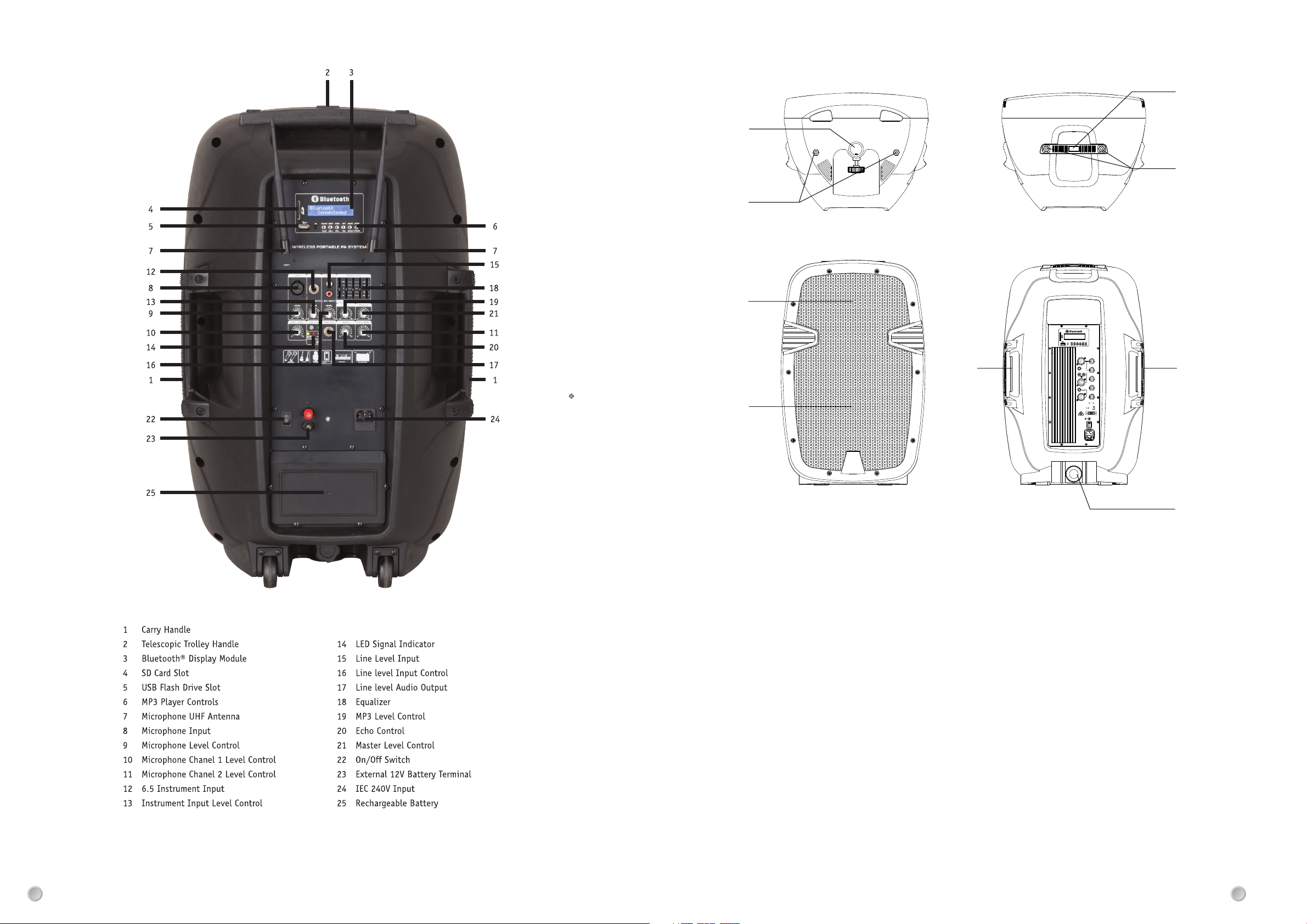
CS-2490 REAR PANEL DESCRIPTION
1
2
3
4
Controls and Features
CS-2 486
LEVEL
MIN MAX
LEVEL
MIC
INPUT
LINE
INPUT
MIN
MAX
VOLUME
L
R
MIN
MAX
TREBLE
LINE
+12
-12
BASS
+12
-12
POWERCLIP
POWER
AC 240V 50Hz
5
2
55
6
1.POLE MO UNT SOCK ET-This s ocket is d esigne d to fit a standard speaker
pole moun t or tripo d speake r stand.
2.RIGGI NG POINT S-This s eries sp eaker ha s rigging points . These points are
to be used to f ly or susp end the sp eaker in the air by some means . Be sure
to follow t he flyin g outlines.
3.HIGH FR EQUENC Y TRANSDUCER - This unit is used to re produc e the high
frequen cy respo nse..
4.WOOFE R-The hi gh-pow ered woofer is used to reproduce the
midrang e and low fr equenc ies.
5.TRANS PORT HAN DLE-Th is serie s speake rs come wi th built -in
heavy-d uty tran sporta tion han dle . Use th is handle for secure
and easy tr anspor tation .
6.POLE MO UNT LOCK ING BOLT- This pin i s used to se cure the
speaker i n place wh en mount ing the sp eaker in a pole mount
configu ration . Always be sure to tighten down on the locki ng
bolt to pre vent the s peaker f rom shif ting during use.
35
 Loading...