


USER MANUAL
INSTALLATION AND QUICK-START GUIDE
CONNECTION GUIDE
OPERATING GUIDE
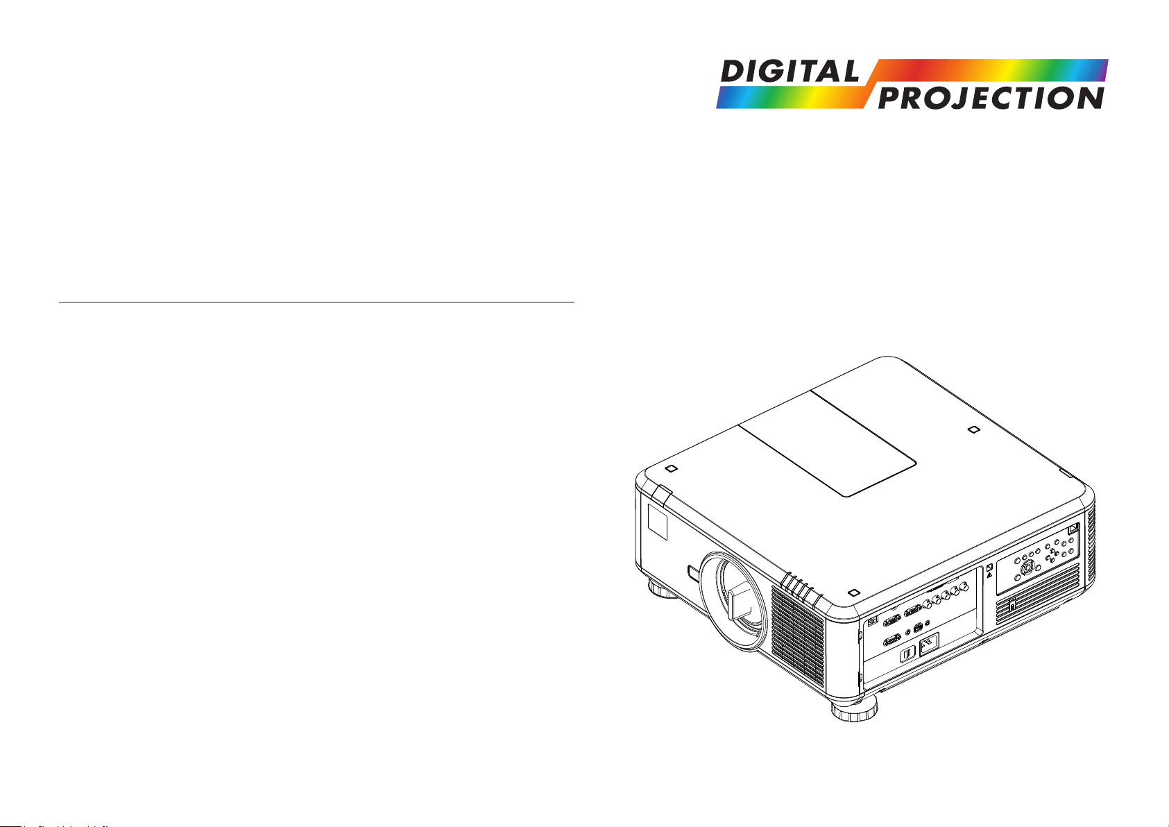
E-Vision 7500 Series
High Brightness Digital Video Projector
REMOTE COMMUNICATIONS GUIDE
Rev D July 2014
114-738D

Digital Projection E-Vision 7500 Series
About This Document
Please follow the instructions in this manual carefully to ensure safe and long-lasting use of the projector.
Keep this manual handy for future reference.
Symbols used in this manual
Many pages in this document have a dedicated area for notes. The information in that area is accompanied by the following symbols:
ELECTRICAL WARNING: this symbol indicates that there is a danger of electrical shock unless the instructions are closely
followed.
WARNING: this symbol indicates that there is a danger of physical injury to yourself and/or damage to the equipment unless
the instructions are closely followed.
NOTE: this symbol indicates that there is some important information that you should read.
Product revision
Because we at Digital Projection continually strive to improve our products, we may change specications and designs, and add new features
without prior notice.
Notes
Legal notice
Trademarks and trade names mentioned in this document remain the property of their respective owners.
Digital Projection disclaims any proprietary interest in trademarks and trade names other than its own.
Copyright © 2014 Digital Projection Ltd. All rights reserved.
iRev D July 2014

Digital Projection E-Vision 7500 Series
Introduction
Congratulations on your purchase of this Digital Projection product.
Your projector has the following key features:
• Swappable color wheels for high brightness and color critical applications.
• HDMI 1.4 for Side by Side, Frame Packing & Top Bottom 3D formats.
• HDBaseT® enables transmission of uncompressed High Denition Video over standard CAT5e/6 LAN cable.
• Motorized and programmable shift, zoom and focus. Intelligent Lens Memory with 10 user-denable preset positions.
• Control via LAN and RS232.
A serial number is located on the back of the projector. Please record it here:
Notes
iiRev D July 2014

Digital Projection E-Vision 7500 Series
CONTENTS
INSTALLATION AND QUICK-START GUIDE ..............................1
WHAT’S IN THE BOX? ................................................................... 3
PROJECTOR OVERVIEW ............................................................... 4
Front view.............................................................................................. 4
Rear view .............................................................................................. 4
Remote control ...................................................................................... 5
Control panel ......................................................................................... 7
Indicators............................................................................................... 7
CHANGING THE LENS, LAMPS, FILTERS AND COLOR WHEEL .... 8
Fitting the lens ....................................................................................... 8
Removing the lens ................................................................................ 8
Changing a lamp ................................................................................... 9
Changing the lters ............................................................................. 10
Changing the color wheel.................................................................... 11
POSITIONING THE SCREEN AND PROJECTOR ........................... 12
OPERATING THE PROJECTOR .................................................... 13
Switching the projector on ................................................................... 13
Selecting an input signal or test pattern .............................................. 13
Input signal ........................................................................................ 13
Test pattern ........................................................................................ 13
Adjusting the lens ................................................................................ 14
Zoom ................................................................................................ 14
Focus ............................................................................................... 14
Shift ................................................................................................. 14
Adjusting the image............................................................................. 14
Orientation ......................................................................................... 14
Aspect Ratio ....................................................................................... 14
Picture .............................................................................................. 14
Switching the projector off ................................................................... 15
CONNECTION GUIDE ............................................................................17
SIGNAL INPUTS AND OUTPUTS .................................................. 19
SUPPORTED SIGNAL INPUT MODES .......................................... 20
CONTROL CONNECTIONS ........................................................... 23
WIRING DETAILS ......................................................................... 24
Signal inputs and outputs .................................................................... 24
HDBaseT input.................................................................................... 24
3D sync connection .............................................................................. 24
HDMI input ......................................................................................... 25
DVI-D ............................................................................................... 26
DisplayPort ........................................................................................ 27
VGA ................................................................................................. 28
COMPONENT .................................................................................... 28
Control connections ............................................................................ 29
LAN connection ................................................................................... 29
RS232 Serial control input ...................................................................... 29
Wired Remote control connection ............................................................ 29
Screen Trigger output ...........................................................................29
iiiRev D July 2014

Digital Projection E-Vision 7500 Series
OPERATING GUIDE ................................................................................31
USING THE MENUS ..................................................................... 34
Navigating the menus ......................................................................... 34
Submenus ........................................................................................... 35
Selecting parameters .......................................................................... 36
Sliders ................................................................................................. 37
Commands .......................................................................................... 37
A TOUR OF THE MENUS .............................................................. 38
INPUT menu ....................................................................................... 38
Input Selection .................................................................................... 38
Test Pattern ........................................................................................ 39
Color Space ....................................................................................... 39
Input Lock .......................................................................................... 39
Background ........................................................................................ 39
Auto Sync Adjust ................................................................................. 39
PICTURE menu .................................................................................. 40
Picture Mode ...................................................................................... 40
Contrast, Brightness, Saturation, Hue ....................................................... 40
Gamma ............................................................................................. 40
Color submenu.................................................................................... 41
Sharpness, Noise Reduction................................................................... 41
Aspect Ratio ....................................................................................... 42
PICTURE menu continued ................................................................... 43
Overscan ........................................................................................... 43
VGA Setup submenu ............................................................................ 43
Auto Sync .......................................................................................... 43
LAMPS menu ...................................................................................... 44
Mode ................................................................................................ 44
Power ............................................................................................... 44
High Altitude Mode ............................................................................... 44
Custom Power Level ............................................................................ 44
Lamp Status ....................................................................................... 44
ALIGNMENT menu ............................................................................. 45
Projection Mode .................................................................................. 45
Fan Mode .......................................................................................... 45
Lens Control ....................................................................................... 45
Lens Memory submenu ......................................................................... 46
Center Lens ....................................................................................... 46
Keystone ........................................................................................... 46
Digital Alignment submenu ..................................................................... 47
H/V Alignment submenu ........................................................................ 47
CONTROL menu ................................................................................. 48
Eco Network Power .............................................................................. 48
Auto Power Off.................................................................................... 48
Auto Power On.................................................................................... 48
Projector Control ................................................................................. 48
Network submenu ................................................................................ 49
Startup Logo ....................................................................................... 49
Trigger .............................................................................................. 49
Auto Search ....................................................................................... 49
Dynamic Black .................................................................................... 49
3D submenu ....................................................................................... 50
Language submenu .............................................................................. 51
SERVICE menu .................................................................................. 52
Information ......................................................................................... 52
Blue Only ........................................................................................... 52
Factory Reset ..................................................................................... 52
MENU MAP .................................................................................. 53
ivRev D July 2014

Digital Projection E-Vision 7500 Series
REMOTE COMMUNICATIONS GUIDE ..........................................57
INTRODUCTION ........................................................................... 59
Operation commands .......................................................................... 59
Key commands ................................................................................... 59
THE OPERATION COMMANDS..................................................... 60
INPUT menu ....................................................................................... 60
PICTURE menu .................................................................................. 61
LAMPS menu ...................................................................................... 64
ALIGNMENT menu ............................................................................. 65
CONTROL menu ................................................................................. 65
SERVICE menu .................................................................................. 67
Miscellaneous commands ................................................................... 67
ERROR CODES ........................................................................... 68
THE KEY COMMANDS ................................................................. 72
WEB CONFIGURATION UTILITY .................................................. 73
Email settings ...................................................................................... 74
Projector controls ................................................................................ 75
vRev D July 2014

INSTALLATION AND QUICK-START GUIDE
E-Vision 7500 Series
High Brightness Digital Video Projector
Rev D July 2014

Digital Projection E-Vision 7500 Series IN THIS GUIDE Installation and Quick-Start Guide
IN THIS GUIDE
What’s In The Box? ............................................................................................. 3
Projector Overview ............................................................................................. 4
Front view ....................................................................................................................4
Rear view .....................................................................................................................4
Remote control ............................................................................................................5
Control panel ...............................................................................................................7
Indicators .....................................................................................................................7
Changing The Lens, Lamps, Filters And Color Wheel ............................. 8
Fitting the lens .............................................................................................................8
Removing the lens ......................................................................................................8
Changing a lamp .........................................................................................................9
Changing the lters ..................................................................................................10
Changing the color wheel ........................................................................................11
Positioning The Screen And Projector ....................................................... 12
Operating The Projector ................................................................................. 13
Switching the projector on .......................................................................................13
Selecting an input signal or test pattern .................................................................13
Input signal ......................................................................................................................13
Test pattern .....................................................................................................................13
Adjusting the lens .....................................................................................................14
Zoom ...............................................................................................................................14
Focus ..............................................................................................................................14
Shift .................................................................................................................................14
Adjusting the image ..................................................................................................14
Orientation ......................................................................................................................14
Aspect Ratio ....................................................................................................................14
Picture .............................................................................................................................14
Switching the projector off .......................................................................................15
Rev D July 2014
Digital Projection E-Vision 7500 Series WHAT’S IN THE BOX? Installation and Quick-Start Guide
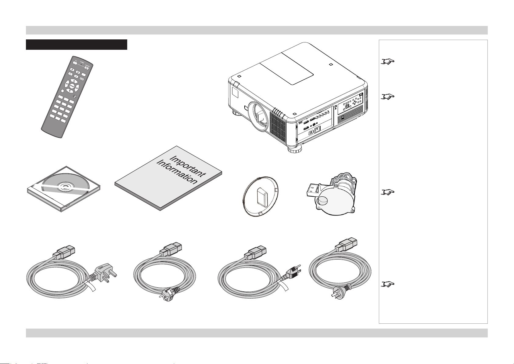
What’s In The Box?
Remote control
(114-230)
User Manual on disc
(115-759)
Important Information
(114-739)
Lens cap
Notes
Make sure your box contains
everything listed. If any pieces are
missing, contact your dealer.
You should save the original box
and packing materials, in case you
ever need to ship your projector.
Projector
An RYGCWB color wheel, optimized
for brightness, is tted as standard.
Use the RGBCMY color wheel for
optimized color.
RGBCMY color wheel
Power cable,
United Kingdom
(112-814)
Power cable,
Europe
(112-816)
Power cable,
North America
(112-815)
Only one power cable - dependent
on the destination territory - will be
supplied with the projector.
Power cable,
China
(112-817)
3Rev D July 2014
Digital Projection E-Vision 7500 Series PROJECTOR OVERVIEW Installation and Quick-Start Guide
Projector Overview
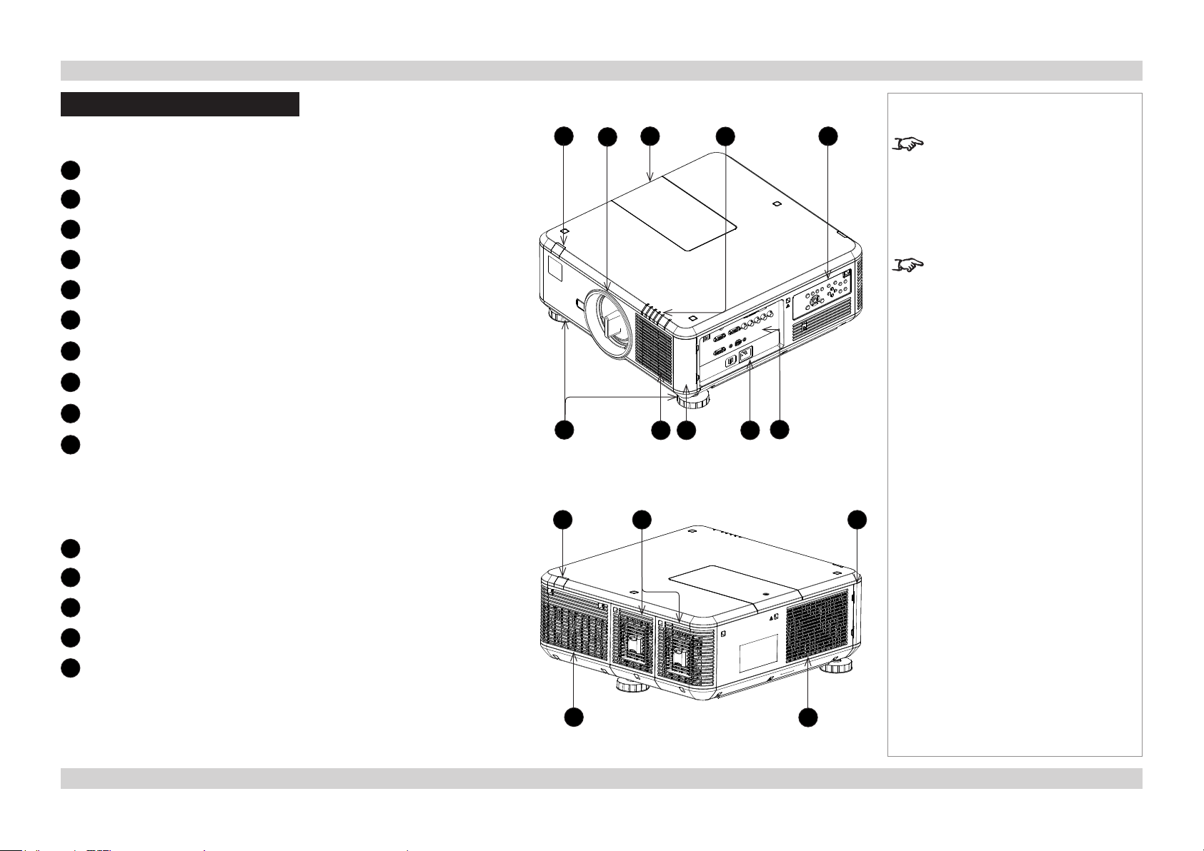
Front view
Front infra-red window
1
2
Lens
3
Color wheel cover
4
Indicator panel
5
Control panel
6
Adjustable feet
7
Air inlet
8
Air lter cover
9
Mains input
10
Connection panel
Notes
1
6
3 5
2
7
4
8 9
The air lters should be cleaned or
changed regularly, depending on the
installation environment.
The lters should be changed at the
same time as the lamp is changed.
The projector lens is shipped
separately.
10
Rear view
Rear infra-red window
1
2
Lamp covers
3
Air lter cover
4
Air outlet
5
Air inlet
1
4
2 3
5
4Rev D July 2014
Digital Projection E-Vision 7500 Series PROJECTOR OVERVIEW Installation and Quick-Start Guide
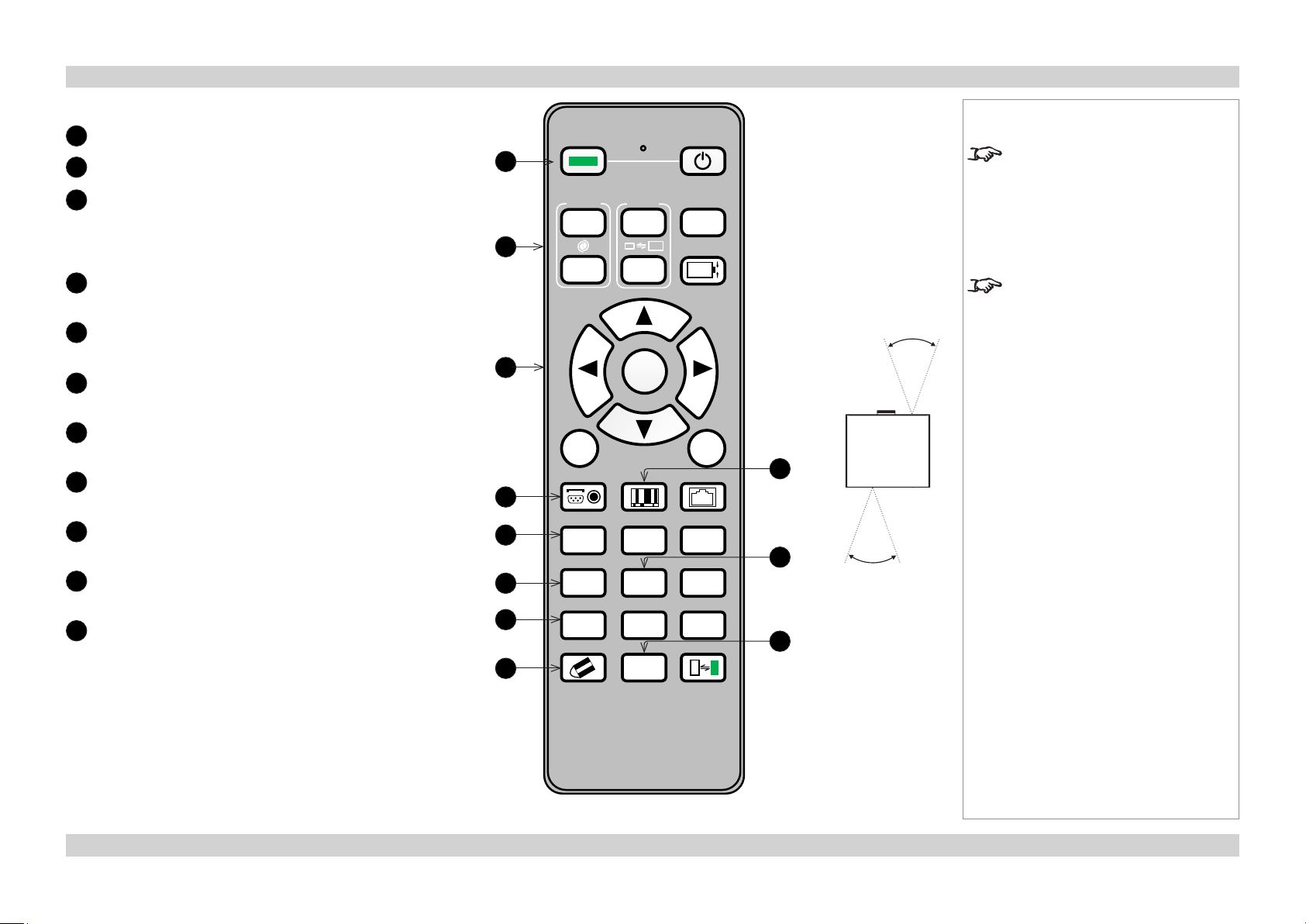
Remote control
Power ON/OFF
1
2
Lens controls
3
Menu controls
Press MENU to open the OSD, then use the buttons to
navigate.
When the OSD is closed, ENTER opens lens controls.
4
INPUT
Select input source.
5
AUTO SYNC
Re-synchronise with the current input signal.
6
OVERSCAN
Select from Off, Crop and Zoom.
7
3D MODE
Access 3D settings.
8
CLEAR
Use only with ID SET.
9
PICTURE
Open the Picture menu.
10
FREEZE
Freeze the current frame.
11
SHUTTER
Notes
ON POWER OFF
1
FOCUS
+
2
3
MENU
INPUT PICTURE NETWORK
4
AUTO SYNC ASPECT BLANK
5
OVERSCAN FREEZE
6
7
CLEAR SHUTTER ID SET
8
ZOOM
+
ENTER
2 31
5 64
INFO.3D MODE
8 97
0
TEST
PATTERN
LENS SHIFT
EXIT
LAMP MODE
LIGHT
40°
9
40°
10
Infra-red
reception
11
The projector can use an infra-red or
a wired remote control.
Some of the controls are duplicated
on the projector control panel, as
shown in the next section.
For full details of how to use the
controls and the menu system, see
the Operating Guide.
5Rev D July 2014
Digital Projection E-Vision 7500 Series PROJECTOR OVERVIEW Installation and Quick-Start Guide
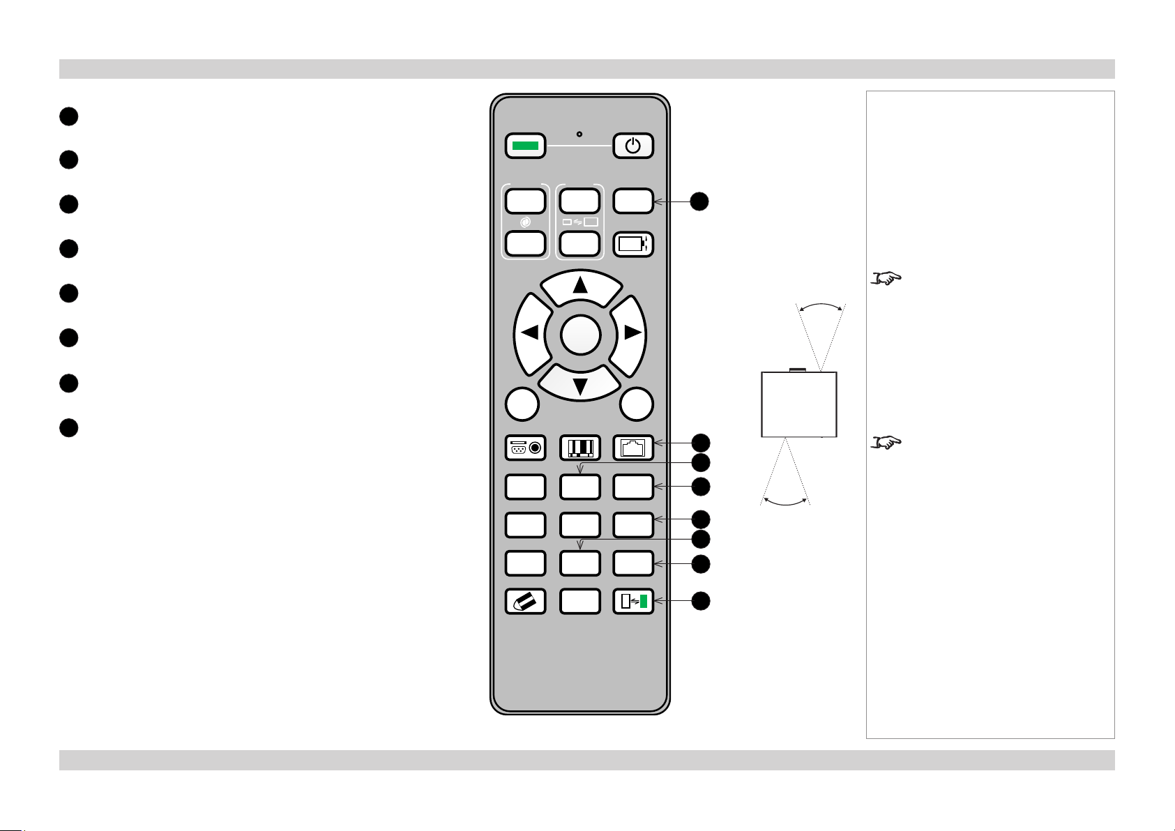
Notes
TEST PATTERN
12
Open the list of available test patterns.
13
NETWORK
Access network settings.
14
ASPECT
Change the aspect ratio.
15
BLANK
Image mute.
16
LAMP MODE
Open the Lamps menu.
17
INFO
Open the Service menu.
18
LIGHT
Illuminate the buttons on the remote control for 10 seconds.
19
ID SET
Hold for 5 seconds to view ID status.
COMBINATION: ID SET + number
Set the ID (Hold for 5 seconds)
COMBINATION: ID SET + CLEAR
Clear the ID (Hold for 5 seconds)
ON POWER OFF
FOCUS
+
MENU
INPUT PICTURE NETWORK
AUTO SYNC ASPECT BLANK
ZOOM
+
ENTER
TEST
PATTERN
LENS SHIFT
EXIT
2 31
OVERSCAN FREEZE
LAMP MODE
5 64
INFO.3D MODE
LIGHT
8 97
CLEAR SHUTTER ID SET
0
12
13
14
15
16
17
18
19
40°
40°
Infra-red
reception
To protect the lamps from thermal
shock, it will not be possible to
change the Lamp Mode more than
once within ve minutes.
Use the ID SET feature to assign
discrete ID addresses for up to nine
projectors. This will enable you to
operate each projector separately
with a dedicated remote control.
6Rev D July 2014
Digital Projection E-Vision 7500 Series PROJECTOR OVERVIEW Installation and Quick-Start Guide
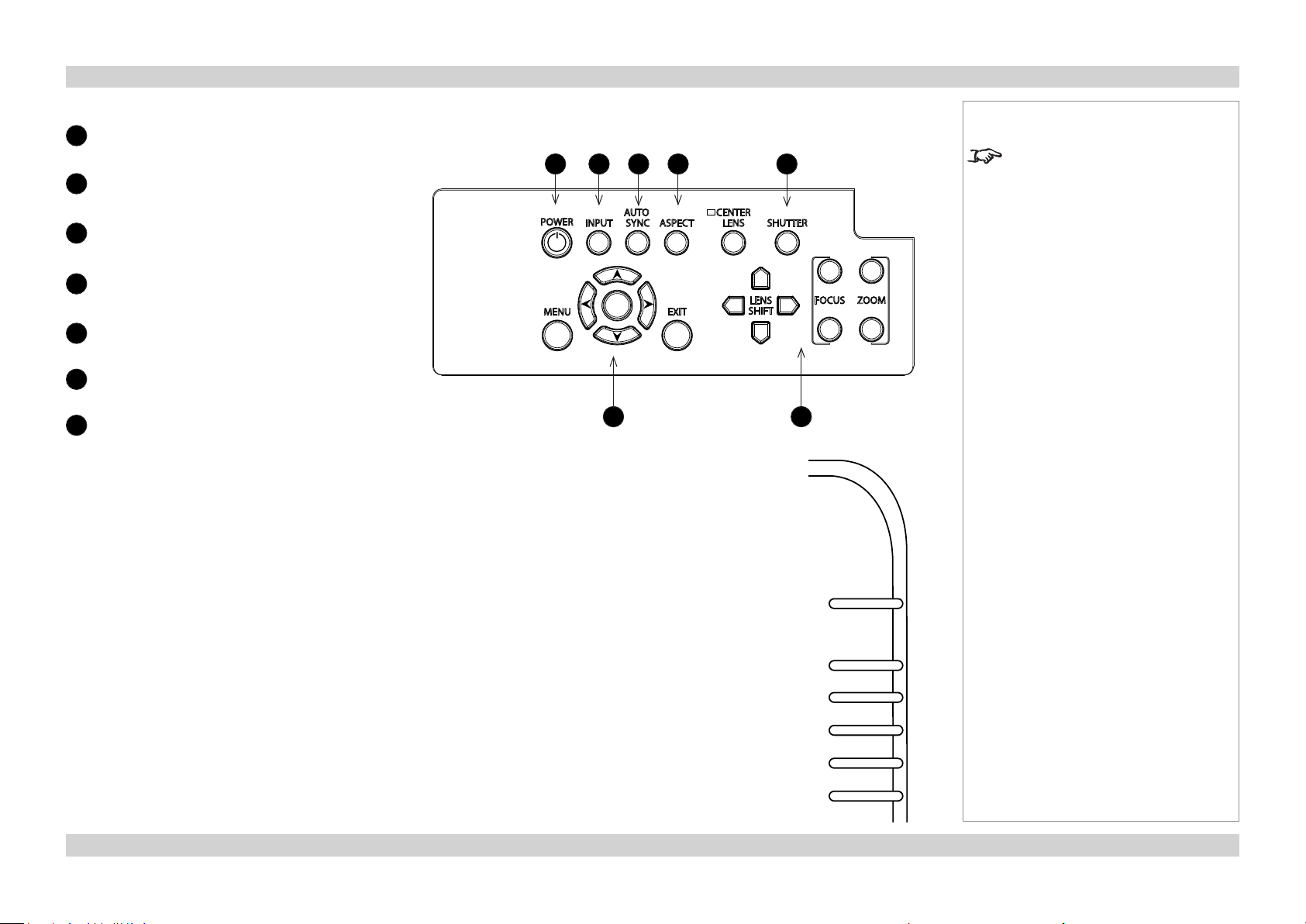
Control panel
POWER
1
Off or Standby.
2
INPUT
Select input source.
3
AUTO SYNC
Re-synchronise with the current input signal.
4
ASPECT
Change the aspect ratio.
5
SHUTTER
6
Menu controls
7
Lens controls
Indicators
POWER off = NO POWER
green = normal RUNNING mode red = STANDBY mode
ashinggreen = PROJECTOR WARM UP
ashingamber = PROJECTOR COOL DOWN
1
2 3 4 5
ENTER
6
Notes
For full details of how to use the
controls and the menu system, see
the Operating Guide.
7
POWER STATUS LAMP1 LAMP2 TEMP. SHUTTER
STATUS off = NO ERROR
ashingred(1ash) = COVER OPEN ashingred(4ashes) = FAN ERROR
red = SYSTEM ERROR
LAMPS 1,2 off = OFF
ashingred = LAMP ERROR red = END OF LIFE
ashinggreen = LAMP WARM-UP green = ON
TEMP off = NO ERROR ashing red = ERROR (temperature)
SHUTTER off = OPEN green = CLOSED
7Rev D July 2014
Digital Projection E-Vision 7500 Series CHANGING THE LENS, LAMPS, FILTERS AND COLOR WHEEL Installation and Quick-Start Guide
Changing The Lens, Lamps, Filters And Color Wheel
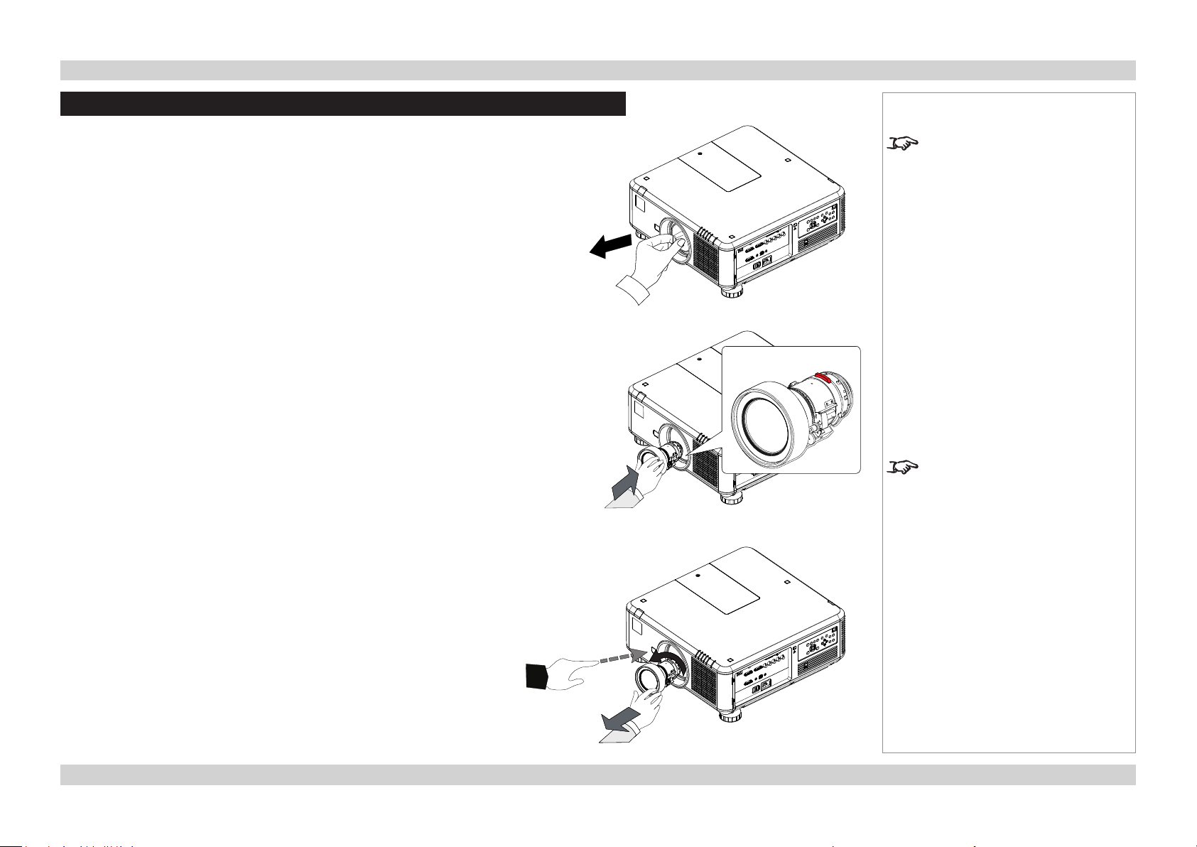
Fitting the lens
1. Remove the lens cap.
2. Position the lens so that the labels are at the top, and gently insert it all
the way into the lens mount.
3. Push the lens in rmly, and turn it clockwise until it clicks into place.
Notes
The projector lens is shipped
separately.
The Center Lens command must
be used after a new lens is inserted.
See the Operating Guide for more
details.
Removing the lens
1. Push in the lens release lever, and turn the lens anti-clockwise.
2. Remove the lens.
8Rev D July 2014
Digital Projection E-Vision 7500 Series CHANGING THE LENS, LAMPS, FILTERS AND COLOR WHEEL Installation and Quick-Start Guide
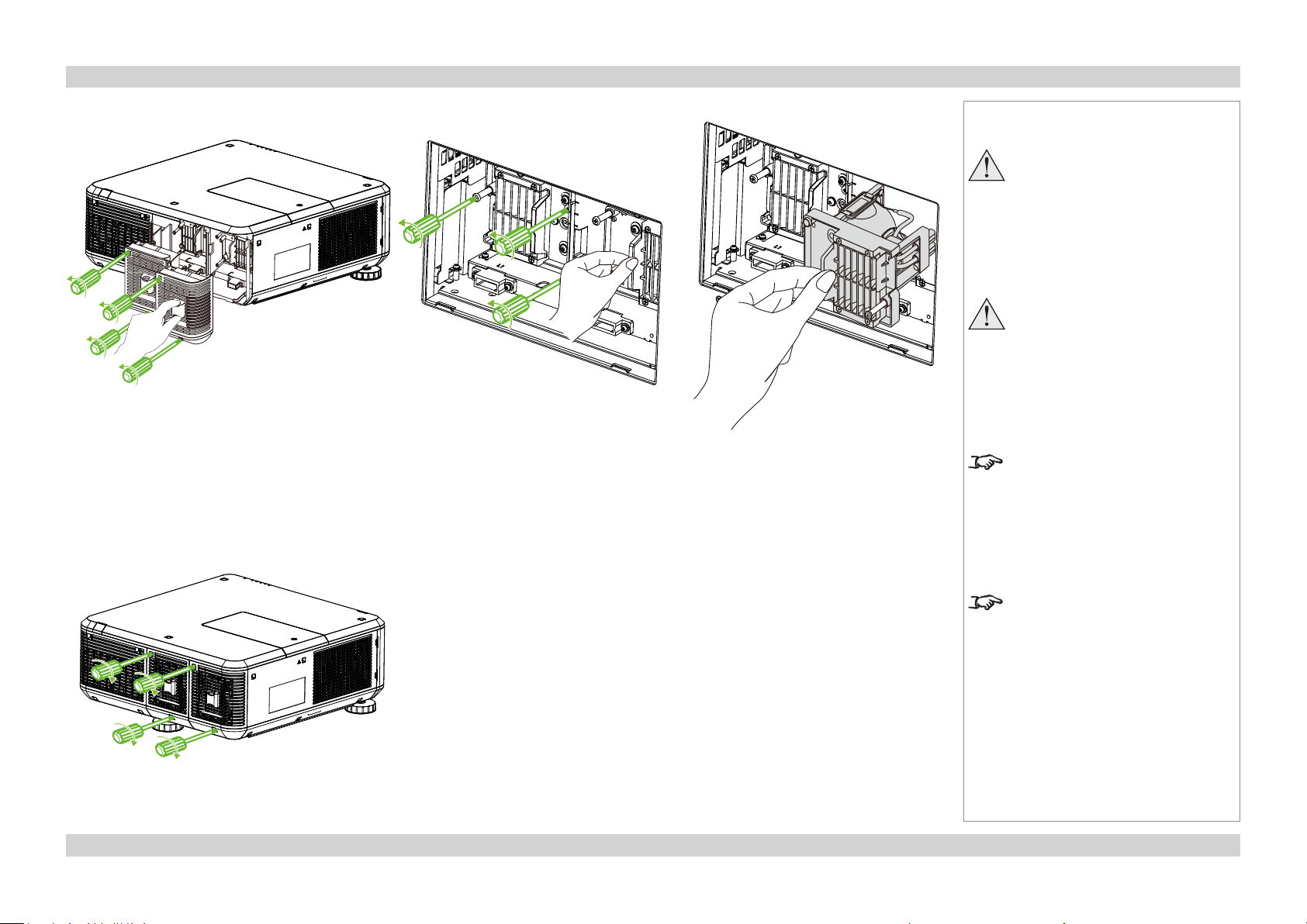
Changing a lamp
1. Unscrew the two captive screws securing the cover for the lamp that needs changing.
2. Open the lamp compartment.
3. Unscrew the three captive screws securing the lamp module.
4. Pull rmly on the handle to remove the lamp module.
5. Insert a new lamp module and fasten the screws.
Notes
Always allow the lamp to cool for
5 minutes before:
- disconnecting the power
- moving the projector
- changing the lamp
The lamp and color wheel must
be changed only by suitably
qualied personnel.
The projector will shut down if any
of the covers are opened whilst in
operation.
6. Replace the lamp compartment cover and fasten the screws.
The lters should be changed at the
same time as the lamp is changed.
9Rev D July 2014
Digital Projection E-Vision 7500 Series CHANGING THE LENS, LAMPS, FILTERS AND COLOR WHEEL Installation and Quick-Start Guide
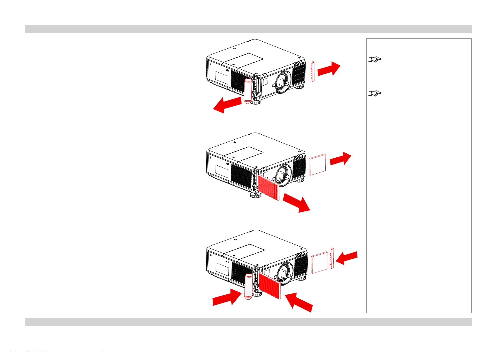
Changing the lters
1. Press the air lter covers, then pull them out as shown in Fig. 1.
2. Pull out the old lters as shown in Fig. 2.
Notes
The projector will shut down if any
of the covers are opened whilst in
operation.
The lters should be changed at the
same time as the lamp is changed.
Fig. 1
Fig. 2
3. Insert the new lters and close the lter covers as shown in Fig. 3.
Fig. 3
10Rev D July 2014
Digital Projection E-Vision 7500 Series CHANGING THE LENS, LAMPS, FILTERS AND COLOR WHEEL Installation and Quick-Start Guide
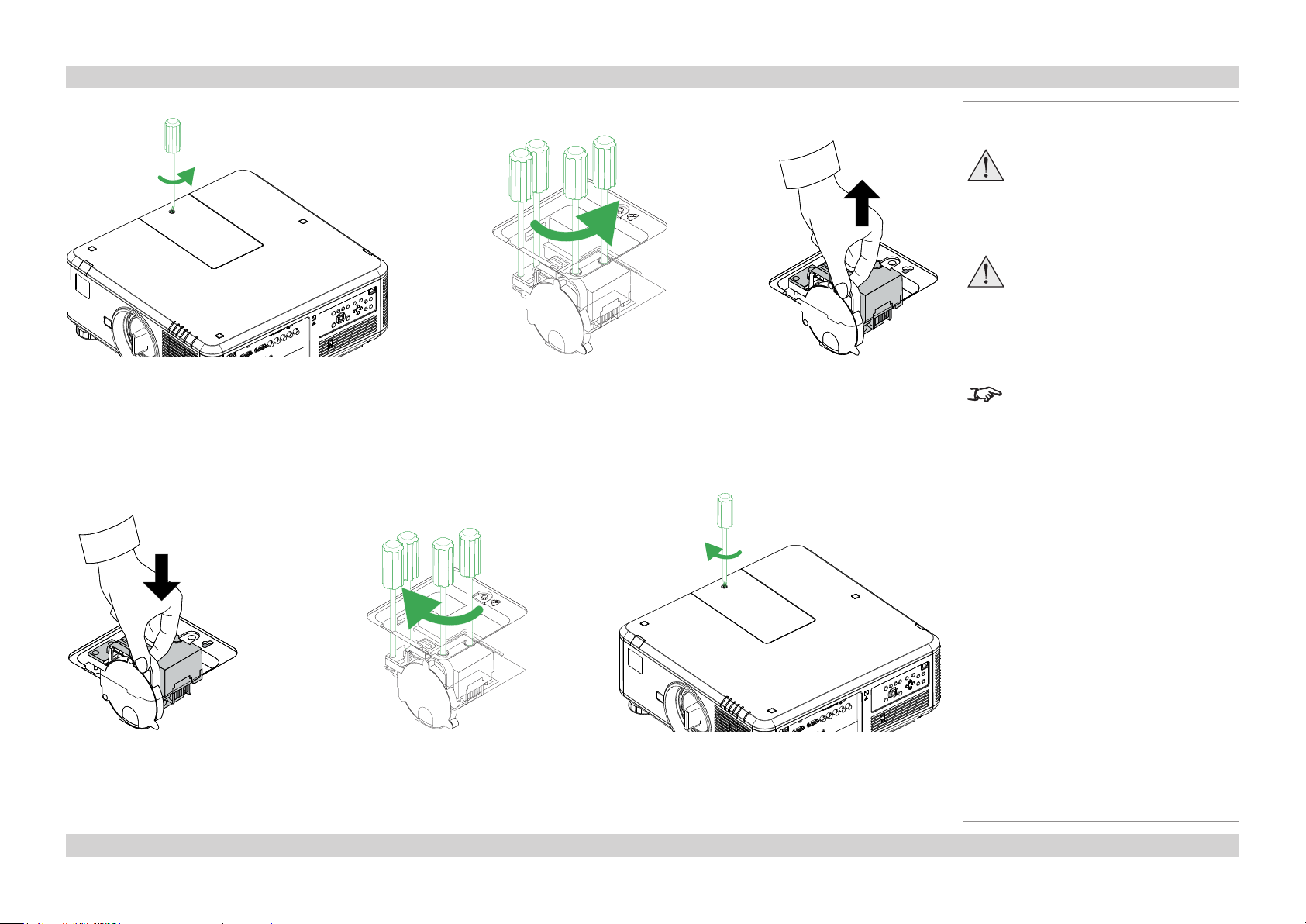
Changing the color wheel
Fig. 1 Fig. 2 Fig. 3
1. Unscrew the captive screw securing the color wheel compartment cover (Fig. 1) and open the compartment.
2. Unscrew the four captive screws securing the color wheel (Fig. 2).
3. Remove the color wheel (Fig. 3).
Notes
The lamp and color wheel must
be changed only by suitably
qualied personnel.
Allow the projector to cool for
5 minutes before changing the
color wheel.
The projector will shut down if any
of the covers are opened whilst in
operation.
Fig. 4
4. Insert a new color wheel (Fig. 4) and fasten the screws (Fig. 5).
5. Replace the cover and fasten the screw (Fig. 6).
Fig. 6Fig. 5
11Rev D July 2014
Digital Projection E-Vision 7500 Series POSITIONING THE SCREEN AND PROJECTOR Installation and Quick-Start Guide
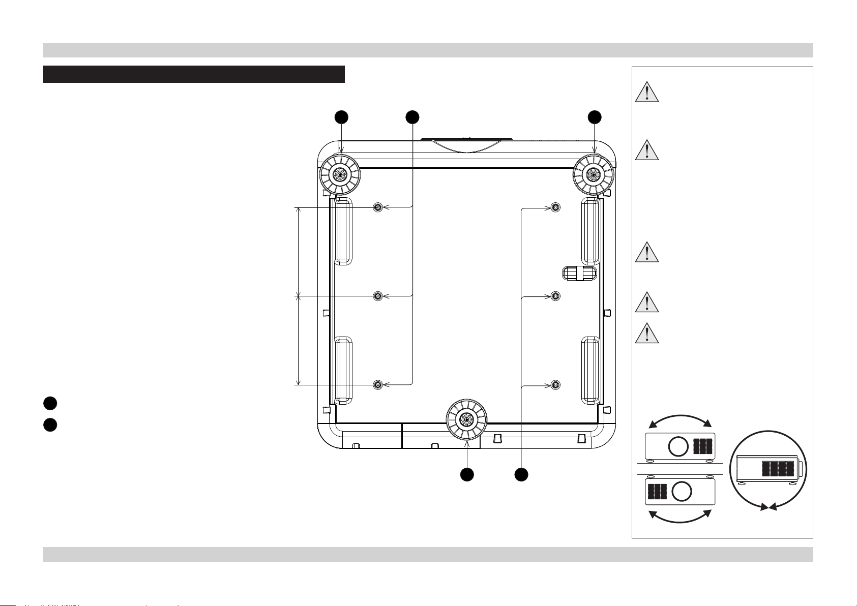
Positioning The Screen And Projector
1. Install the screen, ensuring that it is in the best
position for viewing by your audience.
2. Mount the projector, ensuring that it is at a suitable
distance from the screen for the image to ll the
screen. Set the adjustable feet so that the projector
is level, and perpendicular to the screen.
The drawing shows the positions of the feet for table
mounting, and the xing holes for ceiling mounting.
150 mm150 mm
1 2 1
Notes
Always allow the lamp to cool for
5 minutes before:
- disconnecting the power
- moving the projector
Ensure that there is at least 70
cm (28 in) of space between the
ventilation outlets and any wall,
and 50 cm (20 in) on all other
sides.
If ceiling mounting, ensure there
is 30 cm (12 in) of space between
the projector and ceiling.
Backup safety chains or wires
should always be used with
ceiling mount installations.
Do not stack the projectors.
Do not tilt the projector more than
±10° from side to side when in
use, as this may cause serious
lamp failure, damage the lamp
module and cause extra cost on
replacement.
1
Three adjustable feet
2
Six M4 holes for ceiling mount
The screws should not penetrate more than 15
mm into the body of the projector.
Desktop
±10°
±360°
1 2
±10°
Ceiling
12Rev D July 2014

Digital Projection E-Vision 7500 Series OPERATING THE PROJECTOR Installation and Quick-Start Guide
Operating The Projector
Switching the projector on
1. Connect the power cable between the mains supply and the projector. Switch on at the switch next to the power connector.
2. Wait until the self-test has completed and the Power indicator on the projector control panel shows red. The lamp will be off and the
projector will be in STANDBY mode.
3. Press POWER on the control panel or POWER ON on the remote control.
The Power indicator on the control panel will ash green for a few seconds whilst the lamp comes up to full brightness. When the
projector is ready for use, the Power indicator will show steady green.
Selecting an input signal or test pattern
Input signal
1. Connect an image source to the projector. The signal should be automatically detected by the projector, and should be displayed within
two or three seconds.
2. If more than one signal is connected, select the input you want to display:
• Press INPUT repeatedly on the control panel or remote control to cycle through the inputs.
• or use Input Selection in the INPUT menu.
Notes
For full details of how to connect an
image source to the projector, see
the Connection Guide.
For full details of how to use the
controls and the menu system, see
the Operating Guide.
Test patter n
If you do not have an image source connected to the projector, you can display a test pattern instead:
• Press TEST PATTERN repeatedly on the remote control to cycle through the test patterns,
• or select a Test Patter n from the INPUT menu.
To return to viewing the image from
your image source, scroll through
the test pattern list to Off.
13Rev D July 2014
Digital Projection E-Vision 7500 Series OPERATING THE PROJECTOR Installation and Quick-Start Guide
Adjusting the lens
Zoom
• Use the ZOOM +/− buttons on the control panel or on the remote control to adjust the
lens so that the image lls the screen.
or use Lens Control in the ALIGNMENT menu.
Focus
• Use the FOCUS +/− buttons on the control panel or on the remote control to adjust the
lens until the image is sharp.
or use Lens Control in the ALIGNMENT menu.
Shift
• Use the LENS SHIFT buttons , , and on the control panel to adjust the
position of the image,
or press the LENS SHIFT button on the remote control then use , , and
to adjust the position of the image.
or use Lens Control in the ALIGNMENT menu.
Adjusting the image
Orientation
• This can be set from the ALIGNMENT menu.
Select the orientation which suits the positioning of the projector.
Notes
For full details of how to use the
controls and the menu system, see
the Operating Guide.
Aspect Ratio
• This can be set from the PICTURE menu, or from the ASPECT button on the remote
control or control panel.
Picture
Settings such as Brightness and Contrast can be set from the PICTURE menu.
14Rev D July 2014

Digital Projection E-Vision 7500 Series OPERATING THE PROJECTOR Installation and Quick-Start Guide
Switching the projector off
1. Press and hold POWER on the control panel or POWER OFF on the remote control for 5 seconds.
The lamp will go off, and the Power indicator on the control panel will ash amber for a few seconds whilst the lamp cools. The Power
indicator on the control panel will then show red and the projector will be in Standby mode.
2. Switch off at the switch next to the power connector. Disconnect the power cable from the projector.
Notes
Always allow the lamp to cool for
5 minutes before:
- disconnecting the power
- moving the projector
15Rev D July 2014

Digital Projection E-Vision 7500 Series Installation and Quick-Start Guide
This page is intentionally left blank.
16Rev D July 2014
16
E-Vision 7500 Series
High Brightness Digital Video Projector
CONNECTION GUIDE
Rev D July 2014

Digital Projection E-Vision 7500 Series IN THIS GUIDE Connection Guide
IN THIS GUIDE
Signal Inputs And Outputs ............................................................................. 19
Supported Signal Input Modes ..................................................................... 20
Control Connections ........................................................................................ 23
Wiring Details ..................................................................................................... 24
Signal inputs and outputs ........................................................................................24
HDBaseT input ................................................................................................................24
3D sync connection .........................................................................................................24
HDMI input ......................................................................................................................25
DVI-D ..............................................................................................................................26
DisplayPort ......................................................................................................................27
VGA .................................................................................................................................28
COMPONENT .................................................................................................................28
Control connections .................................................................................................29
LAN connection ...............................................................................................................29
RS232 Serial control input ..............................................................................................29
Wired Remote control connection ...................................................................................29
Screen Trigger output .....................................................................................................29
Rev D July 2014
Digital Projection E-Vision 7500 Series SIGNAL INPUTS AND OUTPUTS Connection Guide
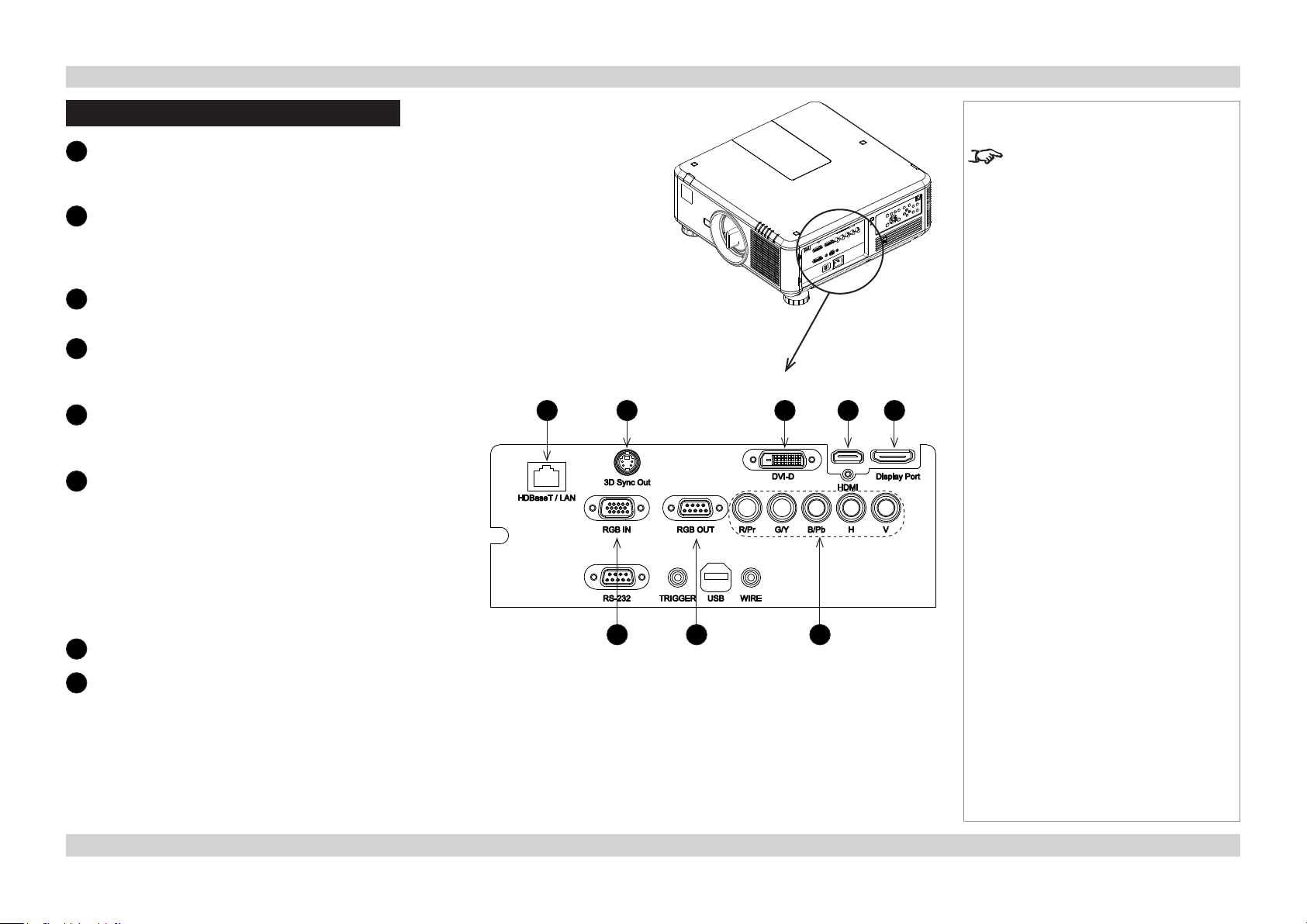
Signal Inputs And Outputs
HDBaseT
1
Receives digital input from HDBaseT-compliant
devices.
2
3D Sync Out
Sync output signal. This may be affected by the 3D
Sync Invert setting in the CONTROL > 3D menu.
Connect this to your IR emitter or ZScreen.
3
DVI-D
Connect a DVI-D cable to the DVI connector.
4
HDMI
HDMI 1.4 input. Connect an HDMI cable to the
connector.
5
DisplayPort
DisplayPort 1.2 input. Connect a DisplayPort cable to
the connector.
6
RGB In
Receives analog signal from a computer. When using
this input, it is best to use a fully wired VGA cable to
connect the source to the projector. This will allow the
source to determine the projector’s capabilities via DDC
and show an optimized image.
Such cables can be identied as they have a blue
connector shell.
Use the INPUT > VGA Setup menu.
7
RGB Out
Notes
For a complete listing of pin
congurations for all signal and
control connectors, see Wiring
Details later in this Guide.
1 2 3 4 5
6 7 8
8
Component
RGBHV, RGsB or RGBS
• Set Color Space in the INPUT menu to Auto or
RGB-Video.
YPbPr or YCbCr
• Set Color Space in the INPUT menu to YPbPr or
YCbCr.
19Rev D July 2014

Digital Projection E-Vision 7500 Series SUPPORTED SIGNAL INPUT MODES Connection Guide
Supported Signal Input Modes
Signal Type Resolution
PC 720x400 70
640x480 59.94
640x480 72
640x480 75
640x480 85
800x600 56
800x600 60.32
800x600 72
800x600 75
800x600 85.06
848x480 47.95
848x480 59.94
1024x768 60
1024x768 70
1024x768 75.03
1024x768 85.03
1280x720 47.95
1280x768 59.87
1280x720 60
1280x800 59.81
Refresh
Rate (Hz)
- RGBHV
COMPONENT
continued on next page...
- YUV
COMPONENT
VGA - RGBHV
VGA - YUV
DVI-D (EIA
Timing)
HDMI - RGB (EIA
Timing)
(EIA Timing)
HDMI - YUV 8-bit
Display Port (EIA
Timing)
Notes
HDBaseT
20Rev D July 2014

Digital Projection E-Vision 7500 Series SUPPORTED SIGNAL INPUT MODES Connection Guide
Notes
Signal Type Resolution
1280x960 60
1280x1024 60.02
1280x1024 75.02
1280x1024 85.02
1366x768 59.79
1440x900 59.887
1600x1200 60
1920x1080 47.95
1680x1050 59.94
1920X1200RB 60
1920X1200 50
1400x900 60
1400X1050 60
Apple Mac 640x480 66.59
832x624 74.54
1152x870 75
NTSC NTSC (M, 4.43) 59.94
PAL PAL (B,G,H,I) 50
PAL (N) 50
PAL (M) 59.94
SECAM SECAM (M) 50
SDTV RGBS 50
Refresh
Rate (Hz)
- RGBHV
COMPONENT
- YUV
COMPONENT
continued on next page...
VGA - RGBHV
VGA - YUV
DVI-D (EIA
Timing)
HDMI - RGB (EIA
Timing)
(EIA Timing)
HDMI - YUV 8-bit
Display Port (EIA
Timing)
HDBaseT
21Rev D July 2014

Digital Projection E-Vision 7500 Series SUPPORTED SIGNAL INPUT MODES Connection Guide
Notes
Signal Type Resolution
1440x480i 60
1440x576i 50
480i 59.94
576i 50
EDTV 480p 59.94
576p 50
HDTV 1035i 60
1080i 50
1080i 59.94
1080i 60
720p 50
720p 59.94
720p 60
1080p 23.98
1080p 24
1080p 25
1080p 29.97
1080p 30
1080p 50
1080p 59.94
1080p 60
Refresh
Rate (Hz)
- RGBHV
COMPONENT
- YUV
COMPONENT
VGA - RGBHV
VGA - YUV
Timing)
DVI-D (EIA
HDMI - RGB (EIA
Timing)
(EIA Timing)
HDMI - YUV 8-bit
Display Port (EIA
Timing)
HDBaseT
22Rev D July 2014

Digital Projection E-Vision 7500 Series CONTROL CONNECTIONS Connection Guide
Control Connections
LAN
1
• The projector’s features can be controlled via a
LAN connection, using commands described in the
Remote Communications Guide.
• Alternatively, use the WebCongurationUtility to
control the projector.
• Crestron RoomView® Express built-in. Enabling
support staff to remotely take control of classroom
technology, perform remote system diagnostics,
track projector usage and log network activity.
• Use a crossed LAN cable to connect directly to a
computer, or an uncrossed cable to connect to a
network hub.
2
RS-232
• The projector’s features can be controlled via a
serial connection, using the control strings described
in the Remote Communications Guide.
• Use a null-modem cable to connect directly to a
computer, or a straight cable to connect to a modem.
3
Screen trigger
The Trigger output can be connected to an electrically
operated screen, automatically deploying the screen
when the projector is switched on, or activating curtains
when the aspect ratio is changed.
4
USB
Service port for rmware updates only.
Notes
For a complete listing of pin
congurations for all signal and
control connectors, see Wiring
Details later in this Guide.
For full details of how to use the
menu system, see the Operating
Guide.
If Eco Network Power is set to
Eco, the LAN connection will be
disabled when the projector is in
STANDBY mode. To enable power
on via LAN, set Eco Network
Power to Standard.
1
2 3 4 5
See www.crestron.com for
further information on Crestron
RoomView® Express.
5
Wired remote control
Connect the remote control using the remote control
cable supplied with the projector.
Plugging in the remote control cable
will disable the infra-red.
23Rev D July 2014

Digital Projection E-Vision 7500 Series WIRING DETAILS Connection Guide
Wiring Details
Signal inputs and outputs
HDBaseT input
RJ45 socket
3D sync connection
Pin 1 +5V
Pin 2 Ground
Pin 3 Stereo sync
Notes
For full details of all input settings,
see the INPUT menu in the
Operating Guide.
HDBaseT input
VESA 3-pin Mini DIN
24Rev D July 2014

Digital Projection E-Vision 7500 Series WIRING DETAILS Connection Guide
HDMI input
19 way type A connector
1 TMDS Data 2+
2 TMDS Data 2 Shield
3 TMDS Data 2-
4 TMDS Data 1+
5 TMDS Data 1 Shield
6 TMDS Data 1-
7 TMDS Data 0+
8 TMDS Data 0 Shield
9 TMDS Data 0-
10 TMDS Clock+
11 TMDS Clock Shield
12 TMDS Clock-
13 CEC
14 not connected
15 SCL (DDC Clock)
16 SCA (DDC Data)
17 DDC/CEC Ground
18 +5 V Power
19 Hot Plug Detect
pin view of panel connector
Notes
For full details of all input settings,
see the INPUT menu in the
Operating Guide.
25Rev D July 2014

Digital Projection E-Vision 7500 Series WIRING DETAILS Connection Guide
DVI-D
24 way D-type connector
1 TMDS Data 2-
2 TMDS Data 2+
3 TMDS Data 2 Shield
4 unused
5 unused
6 DDC Clock
7 DDC Data
8 unused
9 TMDS Data 1-
10 TMDS Data 1+
11 TMDS Data 1 Shield
12 unused
13 unused
14 +5 V Power
15 Ground
16 Hot Plug Detect*
17 TMDS Data 0-
18 TMDS Data 0+
19 TMDS Data 0 Shield
20 unused
21 unused
22 TMDS Clock Shield
23 TMDS Clock+
24 TMDS Clock-
pin view of female connector
Notes
For full details of all input settings,
see the INPUT menu in the
Operating Guide.
* Hot plug detect (HPD) is fully DVI compliant. DVI sources detect the presence of a display
device by providing +5V on pin 14 and looking for +5V on pin 16. Whenever the projector is
operational, and 5V is present on pin 14, pin 16 will be held at +5V.
EDID is available even when the projector is switched off.
Operational means that the projector is powered up. Non operational states are powered
down and some self test and reprogramming modes.
High Denition Content Protection (HDCP) is supported on this input.
26Rev D July 2014

Digital Projection E-Vision 7500 Series WIRING DETAILS Connection Guide
DisplayPort
DisplayPort 1.2
Pin 1 ML_Lane 0 (p) Lane 0 (positive)
Pin 2 GND Ground
Pin 3 ML_Lane 0 (n) Lane 0 (negative)
Pin 4 ML_Lane 1 (p) Lane 1 (positive)
Pin 5 GND Ground
Pin 6 ML_Lane 1 (n) Lane 1 (negative)
Pin 7 ML_Lane 2 (p) Lane 2 (positive)
Pin 8 GND Ground
Pin 9 ML_Lane 2 (n) Lane 2 (negative)
Pin 10 ML_Lane 3 (p) Lane 3 (positive)
Pin 11 GND Ground
Pin 12 ML_Lane 3 (n) Lane 3 (negative)
Pin 13 CONFIG1 connected to Ground1)
Pin 14 CONFIG2 connected to Ground1)
Pin 15 AUX CH (p) Auxiliary Channel (positive)
Pin 16 GND Ground
Pin 17 AUX CH (n) Auxiliary Channel (negative)
Pin 18 Hot Plug Hot Plug Detect
Pin 19 Return Return for Power
Pin 20 DP_PWR Power for connector (3.3 V 500 mA)
pin view of connector
Notes
191115171913 7 5 3
21012161820 14 8 6 4
For full details of all input settings,
see the INPUT menu in the
Operating Guide.
27Rev D July 2014

Digital Projection E-Vision 7500 Series WIRING DETAILS Connection Guide
VGA
15 way D-type connector
1 R
2 G
3 B
4 unused
5 Digital Ground (H Sync)
6 R Ground
7 B Ground
8 G Ground
9 +5v
10 Digital Ground (V Sync/DDC)
11 unused
12 SDA
13 H Sync
14 V Sync
15 SCL
pin view of female connector
Notes
For full details of all input settings,
see the INPUT menu in the
Operating Guide.
COMPONENT
5 x 75 ohm BNC
RGBHV RGsB YPbPr YCbCr
Green Green + Sync Y Y
Blue Blue Pb Cb
Red Red Pr Cr
Hsync
Vsync
Pb/Cb Y Pr/Cr
Blue Green Red
H V
28Rev D July 2014

Digital Projection E-Vision 7500 Series WIRING DETAILS Connection Guide
Control connections
LAN connection
RJ45 socket
RS232 Serial control input
1 unused
2 Received Data (RX)
3 Transmitted Data (TX)
4 unused
5 Signal Ground
6 unused
7 unused
8 unused
9 unused
Wired Remote control connection
3.5mm mini jack
Tip Not connected
Ring Signal
Sleeve Ground
Screen Trigger output
3.5mm mini jack
Tip Signal
Sleeve Ground
LAN connection
pin view of female connector
Tip
Sleeve
Ring
Tip
Sleeve
Notes
For full details of all control settings,
see the CONTROL menu in the
Operating Guide.
Note that plugging in the remote
control cable will disable the infrared.
29Rev D July 2014

Digital Projection E-Vision 7500 Series Connection Guide
This page is intentionally left blank.
30Rev D July 2014
30

E-Vision 7500 Series
High Brightness Digital Video Projector
OPERATING GUIDE
Rev D July 2014

Digital Projection E-Vision 7500 Series IN THIS GUIDE Operating Guide
IN THIS GUIDE
Using The Menus ............................................................................................... 34
Navigating the menus ...............................................................................................34
Submenus ..................................................................................................................35
Selecting parameters ................................................................................................36
Sliders ........................................................................................................................37
Commands .................................................................................................................37
A Tour Of The Menus ....................................................................................... 38
INPUT menu ...............................................................................................................38
Input Selection ................................................................................................................38
Test Pattern .....................................................................................................................39
Color Space ....................................................................................................................39
Input Lock .......................................................................................................................39
Background .....................................................................................................................39
Auto Sync Adjust .............................................................................................................39
PICTURE menu ..........................................................................................................40
Picture Mode ...................................................................................................................40
Contrast, Brightness, Saturation, Hue ............................................................................40
Gamma ...........................................................................................................................40
Color submenu ................................................................................................................41
Sharpness, Noise Reduction ..........................................................................................41
Aspect Ratio ....................................................................................................................42
PICTURE menu continued .................................................................................43
Overscan .........................................................................................................................43
VGA Setup submenu ......................................................................................................43
Auto Sync ........................................................................................................................43
LAMPS menu .............................................................................................................44
Mode ...............................................................................................................................44
Power ..............................................................................................................................44
High Altitude Mode ..........................................................................................................44
Custom Power Level .......................................................................................................44
Lamp Status ....................................................................................................................44
ALIGNMENT menu ....................................................................................................45
Projection Mode ..............................................................................................................45
Fan Mode ........................................................................................................................45
Lens Control ....................................................................................................................45
Lens Memory submenu ..................................................................................................46
Center Lens ....................................................................................................................46
Keystone .........................................................................................................................46
Digital Alignment submenu .............................................................................................47
H/V Alignment submenu .................................................................................................47
CONTROL menu ........................................................................................................48
Eco Network Power ........................................................................................................48
Auto Power Off ................................................................................................................48
Auto Power On ................................................................................................................48
Projector Control .............................................................................................................48
Network submenu ...........................................................................................................49
Startup Logo ...................................................................................................................49
Trigger .............................................................................................................................49
Auto Search ....................................................................................................................49
Dynamic Black ................................................................................................................49
3D submenu ....................................................................................................................50
Language submenu ........................................................................................................51
SERVICE menu ..........................................................................................................52
Information ......................................................................................................................52
Blue Only ........................................................................................................................52
Factory Reset ..................................................................................................................52
continued
Rev D July 2014

Digital Projection E-Vision 7500 Series IN THIS GUIDE Operating Guide
Menu Map............................................................................................................. 53
INPUT .........................................................................................................................53
PICTURE ....................................................................................................................53
LAMPS ........................................................................................................................54
ALIGNMENT ..............................................................................................................54
CONTROL ..................................................................................................................55
SERVICE ....................................................................................................................55
Rev D July 2014

Digital Projection E-Vision 7500 Series USING THE MENUS Operating Guide
Using The Menus
Use the buttons on the projector control
panel or on the remote control, to
access the menu system.
• To open the on-screen display
(OSD), press MENU. To close,
press EXIT/RETURN.
Navigating the menus
• Select a menu using
and ,
• then open the menu by pressing
.
The rst item in the menu is
highlighted.
• Select an item in the menu using
and .
• To open another menu, rst close
the current menu by pressing
MENU.
MENU 1
Menu 1
Menu 1
Menu 1
Menu 1
Menu 1
Menu 1
Projector control panel
MENU 2 MENU 3
MENU 1
Menu 2
Menu 2
Menu 2
Menu 2
Menu 2
Menu 2
MENU 2 MENU 3
MENU 1
Menu 2
Menu 2
Menu 2
Menu 2
Menu 2
Menu 2
MENU 4
Menu 2
Menu 2
Menu 2
Menu 2
Menu 2
Menu 2
MENU 5
MENU 4
MENU 2 MENU 3
MENU 1
MENU 2 MENU 3
MENU 6
MENU 5
MENU 4
Remote control
MENU 6
MENU 5
MENU 4
MENU 6
MENU 5
NotesNotes
Some menu options and controls
may not be available due to settings
in other menus. These will be
shaded grey on the actual menu.
MENU 6
34Rev D July 2014

Digital Projection E-Vision 7500 Series USING THE MENUS Operating Guide
Submenus
• Select a submenu using
and .
• then open the submenu by pressing
ENTER.
The submenu appears to the right side
of the menu it was called from.
The name of the submenu is shown at
the top.
• To close the submenu, press MENU.
Sometimes, a submenu leads to a subsubmenu:
• Select the sub-submenu using
and .
• then open it by pressing ENTER.
The sub submenu appears below the
submenu it was called from.
The name of the sub submenu is shown
at the top.
• To close the sub submenu, press
MENU.
MENU 1
Selection < Item >
Submenu 1 Enter
Submenu 2 Enter
Slider < 100 >
Command Execute
MENU 1
Selection < Item >
Submenu 1 Enter
Submenu 2 Enter
Slider < 100 >
Command Execute
MENU 2 MENU 3
MENU 1
Selection < Item >
Submenu 1 Enter
Submenu 2 Enter
Slider < 100 >
Command Execute
MENU 2 MENU 3
MENU 1
Selection < Item >
Submenu 1 Enter
Submenu 2 Enter
Slider < 100 >
Command Execute
MENU 4
MENU 2 MENU 3
MENU 4
Submenu 1 Item
Submenu 1 Item
Sub-submenu Enter
Submenu 1 Item
MENU 2 MENU 3
MENU 5
MENU 5
Submenu 1
MENU 6
MENU 4
Submenu 1 Item
Submenu 1 Item
Submenu 1 Item
Submenu 1 Item
MENU 6
MENU 4
Submenu 1 Item
Submenu 1 Item
Sub-submenu Enter
Submenu 1 Item
MENU 5
Submenu 1
MENU 5
Submenu 1
Notes
Some menu options and controls
may not be available due to settings
in other menus. These will be
shaded grey on the actual menu.
MENU 6
MENU 6
Sub-submenu
Sub-submenu Item
Sub-submenu Item
Sub-submenu Item
Sub-submenu Item
35Rev D July 2014

Digital Projection E-Vision 7500 Series USING THE MENUS Operating Guide
Selecting parameters
Most parameters are changed by selecting from a list:
• Select from the list using
and .
• The change will usually be made immediately.
Sometimes you can open the list in the same way you
open a submenu.
• Press ENTER to open the list.
The list appears to the right of the menu it was
called from.
• The item that is currently selected is marked with a
block: .
• Select from the submenu using
and .
• The change will be made when you press ENTER
to conrm the selection.
MENU 1
Submenu Enter
Selection < Item 1 >
Slider < 100 >
Command Execute
MENU 1
Submenu Enter
Selection Enter
Slider < 100 >
Command Execute
MENU 2 MENU 3
MENU 1
Submenu Enter
Selection < Item 2 >
Slider < 100 >
Command Execute
MENU 2 MENU 3
MENU 2 MENU 3
MENU 4
MENU 4
§ Item 1
MENU 5
MENU 5
Selection
Item 2
Item 3
Item 4
MENU 4
MENU 6
MENU 5
MENU 6
MENU 6
Notes
Some menu options and controls
may not be available due to settings
in other menus. These will be
shaded grey on the actual menu.
There may be a short delay when
changing some parameters, due to
internal processing time.
36Rev D July 2014

Digital Projection E-Vision 7500 Series USING THE MENUS Operating Guide
Sliders
• Use or to adjust the value.
The menu will disappear, to be replaced by a slider bar.
• To return to the menu, press MENU.
Commands
• To execute the command, press ENTER.
In this example,
• use or to move the blue highlight to OK or Cancel,
• then press ENTER to conrm your selection.
MENU 1
Submenu Enter
Selection < Item 2 >
Slider < 100 >
Command Execute
Slider 100
MENU 1
Submenu Enter
Selection < Item 2 >
Slider < 100 >
Command Execute
MENU 2 MENU 3
MENU 2
MENU 3
MENU 4
MENU 4
MENU 5
MENU 5
MENU 6
MENU 6
Notes
Some menu options and controls
may not be available due to settings
in other menus. These will be
shaded grey on the actual menu.
Confirm
OK Cancel
37Rev D July 2014

Digital Projection E-Vision 7500 Series A TOUR OF THE MENUS Operating Guide
A Tour Of The Menus
INPUT menu
Input Selection
• Press ENTER to open the Input Selection menu, then select an
input from the list.
INPUT
Input Selection Enter
Test Pattern Enter
Color Space < Auto >
Input Lock < Auto >
Background < Logo >
Auto Sync Adjust < Always >
INPUT
Input Selection Enter
Test Pattern Enter
Color Space < Auto >
Input Lock < Auto >
Background < Logo >
Auto Sync Adjust < Always >
PICTURE LAMPS ALIGNMENT CONTROL SERVICE
PICTURE LAMPS ALIGNMENT CONTROL SERVICE
Notes
See also Using the Menus, earlier
in this guide and Menu Map, later in
this guide.
Input Selection
· HDMI
DVI
VGA
Component / BNC
Display Port
HDBase T
38Rev D July 2014

Digital Projection E-Vision 7500 Series A TOUR OF THE MENUS Operating Guide
INPUT menu continued
Test Pattern
• Press ENTER to display a Test Pattern.
• Use or to scroll through the following Test Patterns:
... Off, Color Bar, Crosshatch, Burst, Red, Green, Blue, White,
Black, H Ramp, Uncorrected Red, Uncorrected Green,
Uncorrected Blue, Uncorrected White, Uncorrected Black,
Off ...
• To return to viewing the image from your image source,
use or to scroll through the list to Off.
Color Space
• Set this to Auto, except when the projector has problems selecting
between YCrCb, YPrPb, RGB-PC and RGB-Video.
Input Lock
• Set this to Auto, except when the projector has problems locking
on to 48Hz, 50Hz and 60Hz signals.
INPUT
Input Selection Enter
Test Pattern Enter
Color Space < Auto >
Input Lock < Auto >
Background < Logo >
Auto Sync Adjust < Always >
PICTURE LAMPS ALIGNMENT CONTROL SERVICE
Test Pattern
Color Bar
Crosshatch
Burst
Red
Green
Blue
White
Black
H Ramp
Uncorrected Red
Uncorrected Green
Uncorrected Blue
Uncorrected White
Uncorrected Black
· Off
Notes
See also Using the Menus, earlier
in this guide and Menu Map, later in
this guide.
Background
• Set this to determine what appears on screen when the projector is
searching for a valid input source.
Auto Sync Adjust
• Select from
• Off: Auto Sync Adjustment is never performed.
• Auto – Projector will compare with the previous ve signals
stored in memory, and then recall those settings if possible.
• Always - Projector will perform auto setup every time a new
signal source is connected, ignoring any settings in memory.
39Rev D July 2014

Digital Projection E-Vision 7500 Series A TOUR OF THE MENUS Operating Guide
PICTURE menu
Picture Mode
• Select one of the Picture modes as required.
Contrast, Brightness, Saturation, Hue
• Adjust the sliders for these settings, as required.
Gamma
• Select one of the Gamma settings as required.
INPUT
Picture Mode < High Bright >
Contrast < 100 >
Brightness < 100 >
Saturation < 100 >
Hue < 100 >
Gamma < Video >
Color Enter
Sharpness < 0 >
Noise Reduction < 0 >
Aspect Ratio < Letterbox >
Overscan < Off >
VGA Setup Enter
Autosync Execute
PICTURE
LAMPS ALIGNMENT CONTROL SERVICE
Notes
See also Using the Menus, earlier
in this guide and Menu Map, later in
this guide.
40Rev D July 2014

Digital Projection E-Vision 7500 Series A TOUR OF THE MENUS Operating Guide
PICTURE menu continued
Color submenu
• Press ENTER to open the Color submenu.
Color Temperature
• Native gives you the brightest possible image.
• A value between 5000K and 9300K selects the relevant color
temperature.
Trim
• Set the Red, Green and Blue Lift and Gain settings, to improve the
appearance of the projected image.
Hue, Saturation, Gain
• Set the Red, Green, Blue, Cyan, Magenta and Yellow settings as
required.
White Balance
• Set the Red, Green and Blue levels as required.
INPUT
Picture Mode < High Bright >
Contrast < 100 >
Brightness < 100 >
Saturation < 100 >
Hue < 100 >
Gamma < Video >
Color Enter
Sharpness < 0 >
Noise Reduction < 0 >
Aspect Ratio < Letterbox >
Overscan < Off >
VGA Setup Enter
Autosync Execute
PICTURE
LAMPS ALIGNMENT CONTROL SERVICE
Color
Color Temperature < Native >
Trim Enter
Hue Enter
Saturation Enter
Gain Enter
White Balance Enter
Trim
Red Lift < 0 >
Green Lift < 0 >
Blue Lift < 0 >
Red Gain < 0 >
Green Gain < 0 >
Blue Gain < 0 >
Hue
Red < 0 >
Green < 0 >
Blue < 0 >
Cyan < 0 >
Magenta < 0 >
Yellow < 0 >
White Balance
Red < 0 >
Green < 0 >
Blue < 0 >
Notes
See also Using the Menus, earlier
in this guide and Menu Map, later in
this guide.
Sharpness, Noise Reduction
• Adjust the sliders for these settings, as required.
41Rev D July 2014

Digital Projection E-Vision 7500 Series A TOUR OF THE MENUS Operating Guide
PICTURE menu continued
Aspect Ratio
• Set Aspect Ratio to suit the incoming video
signal.
The 5:4, 4:3, 16:10, 16:9, 1.88:1 and 2.35:1
settings will stretch the image to the selected
aspect ratio, leaving black bars at the top and
bottom or sides of the screen, depending on
the aspect ratio of the projector.
The Letterbox setting can be used where
a wide screen image has been supplied in a
narrower format with black bars at the top and
bottom. The top and bottom of the image will
be cropped,and the image stretched to ll the
screen.
The Native setting will scale the image to t
either the full height or width of the screen,
whilst retaining the aspect ratio of the image.
The Unscaled setting will display the image
pixel for pixel at its supplied resolution, in the
centre of the screen. There may be black bars
at the top and bottom or sides of the screen,
or the image may be cropped, depending on
the video signal and the aspect ratio of the
projector.
16:10 image
5:4 image
displayed at 5:4
displayed unscaled
Notes
See also Using the Menus, earlier
in this guide and Menu Map, later in
this guide.
displayed at 2.35:1
displayed at native
letterbox image
stretched and cropped
42Rev D July 2014

Digital Projection E-Vision 7500 Series A TOUR OF THE MENUS Operating Guide
PICTURE menu continued
Overscan
• Set this to Off, On or Zoom as required.
VGA Setup submenu
• Press ENTER to open the VGA Setup submenu.
H Total, H Start, H Phase, V Start
• Adjust the sliders for these settings, as required to suit the incoming
image.
Auto Sync
• Press ENTER to force the projector to re-synchronise with the input
signal.
INPUT
Picture Mode < High Bright >
Contrast < 100 >
Brightness < 100 >
Saturation < 100 >
Hue < 100 >
Gamma < Video >
Color Enter
Sharpness < 0 >
Noise Reduction < 0 >
Aspect Ratio < Letterbox >
Overscan < Off >
VGA Setup Enter
Autosync Execute
PICTURE
LAMPS ALIGNMENT CONTROL SERVICE
VGA Setup
H Total < 100 >
H Start < 100 >
H Phase < 100 >
V Start < 100 >
Notes
Overscan is used to compensate
for noisy or badly dened image
edges, by cropping the image, or
increasing the size of the image to
force the edges off screen.
You can also press the AUTO SYNC
button on the remote control or
control panel to re-synchronise the
image.
See also Using the Menus, earlier
in this guide and Menu Map, later in
this guide.
43Rev D July 2014

Digital Projection E-Vision 7500 Series A TOUR OF THE MENUS Operating Guide
LAMPS menu
Mode
• Set this to Dual, Lamp 1, Lamp 2 or Single as required.
When the mode is changed, it will not be possible to change it again
within ve minutes.
Power
• Set this to Normal for 100% power, Eco for 80% power or Custom
to enable the Custom Power slider.
High Altitude Mode
• Set this to On if it is necessary to have the cooling fans running at
high speed.
Custom Power Level
• Set the slider as required.
Lamp Status
• For information only.
INPUT
Mode < Dual >
Power < Normal >
High Altitude < Off >
Custom Power Level < 100% >
Lamp 1 Status < On >
Lamp 2 Status < On >
PICTURE
LAMPS
ALIGNMENT CONTROL SERVICE
Notes
When Mode is set to Single, the
projector will turn on using the lamp
with the least hours of use.
To protect the lamps from thermal
shock, it will not be possible to
change the Mode more than once
within ve minutes.
The Power setting should be set
to Custom if you want to use the
Custom Power Level slider.
See also Using the Menus, earlier
in this guide and Menu Map, later in
this guide.
44Rev D July 2014

Digital Projection E-Vision 7500 Series A TOUR OF THE MENUS Operating Guide
ALIGNMENT menu
Projection Mode
• Front and Rear dene whether the projector is in front of the screen
or behind it.
Set to Ceiling + Front or Ceiling + Rear if the projector is ceiling
mounted.
Fan Mode
• Adjusts the fan speeds to optimise cooling when the projector is in
vertical orientation.
Set to Up or Down as appropriate when projecting lens up or down.
Lens Control
1. Press ENTER to display the Lens Control box.
2. Press ENTER again to switch between SHIFT and ZOOM/FOCUS
mode.
3. Use , , and to adjust the lens as necessary.
INPUT
Projection Mode < Front >
Fan Mode < Normal >
Lens Control Enter
Lens Memory Enter
Center Lens Execute
Keystone < 0 >
Digital Alignment Enter
H/V Alignment Enter
PICTURE LAMPS
Lens Control
Zoom
Focus
Enter to Shift
ALIGNMENT
CONTROL SERVICE
Lens Control
Shift V
Shift H
Enter to Zoom/Focus
Notes
See also Using the Menus, earlier
in this guide and Menu Map, later in
this guide.
45Rev D July 2014

Digital Projection E-Vision 7500 Series A TOUR OF THE MENUS Operating Guide
ALIGNMENT menu continued
Lens Memory submenu
The current lens position, focus and zoom settings can be saved in
one of ten memories, for later recall.
• Press ENTER to open the Lens Memory submenu.
Save Memory
• Press ENTER to open the Save Memory submenu.
• Use and to select from Lens Memory 1
to Lens Memory 10.
• Press ENTER to save the current settings.
Load Memory
• Press ENTER to open the Load Memory submenu.
• Use and to select from Lens Memory 1
to Lens Memory 10.
• Press ENTER to recall the saved settings.
Center Lens
• Press ENTER to center the lens.
INPUT
Projection Mode < Front >
Fan Mode < Normal >
Lens Control Enter
Lens Memory Enter
Center Lens Execute
Keystone < 0 >
Digital Alignment Enter
H/V Alignment Enter
PICTURE LAMPS
ALIGNMENT
Load Memory Enter
Save Memory Enter
CONTROL SERVICE
Lens Memory
Notes
See also Using the Menus, earlier
in this guide and Menu Map, later in
this guide.
The Center Lens command must
be used after a new lens is inserted.
Keystone
• Use the Keystone control to correct for any distortion caused by
the projector being in a different vertical plane to the screen.
46Rev D July 2014

Digital Projection E-Vision 7500 Series A TOUR OF THE MENUS Operating Guide
ALIGNMENT menu continued
Digital Alignment submenu
• Press ENTER to open the Digital Alignment submenu.
Digital Zoom, Digital Pan, Digital Scan
• Use and to select a digital alignment control.
• Set the slider as required.
Reset
• Press ENTER to reset all Digital Alignment settings to zero.
H/V Alignment submenu
• Press ENTER to open the H/V Alignment submenu.
H Zoom, V Zoom, H Shift, V Shift
• Use and to select an alignment control.
• Set the slider as required.
Reset
• Press ENTER to reset all H/V Alignment settings to zero.
INPUT
Projection Mode < Front >
Fan Mode < Normal >
Lens Control Enter
Lens Memory Enter
Center Lens Execute
Keystone < 0 >
Digital Alignment Enter
H/V Alignment Enter
INPUT
Projection Mode < Front >
Fan Mode < Normal >
Lens Control Enter
Lens Memory Enter
Center Lens Execute
Keystone < 0 >
Digital Alignment Enter
H/V Alignment Enter
PICTURE LAMPS
PICTURE LAMPS
ALIGNMENT
Digital Zoom < 0 >
Digital Pan < 0 >
Digital Scan < 0 >
Reset Execute
ALIGNMENT
H Zoom < 0 >
V Zoom < 0 >
H Shift < 0 >
V Shift < 0 >
Reset Execute
CONTROL SERVICE
Digital Alignment
CONTROL SERVICE
H/V Alignment
Notes
See also Using the Menus, earlier
in this guide and Menu Map, later in
this guide.
H Shift will only work if the image
has been reduced horizontally using
H Tuning. Likewise, V Shift will
only work once V Tuning has been
applied.
47Rev D July 2014

Digital Projection E-Vision 7500 Series A TOUR OF THE MENUS Operating Guide
CONTROL menu
Eco Network Power
• Set this to Standard or Eco as required. In Eco mode, when the
projector is in STANDBY mode, the LAN connection is disabled.
Auto Power Off
• Set this to On if you want the projector to go into Standby mode
when no input source is detected for 20 minutes.
Auto Power On
• Set this to On if you want the projector to start up immediately when
the mains is connected.
• Set this to Off if you want the projector to go into Standby mode
when the mains is connected. In this case, the projector will not
start up until the POWER button is pressed on the control panel or
the remote control.
Projector Control
• Set this to RS232, Network or Both as required.
INPUT
Eco Network Power < Standard >
Auto Power Off < Off >
Auto Power On < Off >
Projector Control < Network >
Network Enter
Startup Logo < On >
Trigger < Auto >
Auto Search < Off >
Dynamic Black < On >
3D Enter
Language Enter
PICTURE LAMPS
ALIGNMENT
CONTROL
SERVICE
Notes
Eco Network Power must be set to
Standard if you wish to be able to
switch the projector on via LAN.
See also Using the Menus, earlier
in this guide and Menu Map, later in
this guide.
48Rev D July 2014

Digital Projection E-Vision 7500 Series A TOUR OF THE MENUS Operating Guide
CONTROL menu continued
Network submenu
• Press ENTER to open the Network submenu.
Set DHCP to Off to enable manual editing of the IP Address,
Subnet Mask and Gateway elds. If DHCP is On, these elds are
updated automatically and manual editing is disabled.
Startup Logo
• Set this to On if you want the DP logo to show when the projector is
rst switched on.
Trigger
• Set this to Auto if you want the Trigger output to be activated when
the projector is rst switched on.
• Set this to one of the Aspect Ratio settings, if you want the
Trigger output to be activated when the projector is switched to
that aspect ratio.
INPUT
Eco Network Power < Standard >
Auto Power Off < Off >
Auto Power On < Off >
Projector Control < Network >
Network Enter
Startup Logo < On >
Trigger < Auto >
Auto Search < Off >
Dynamic Black < On >
3D Enter
Language Enter
PICTURE LAMPS
ALIGNMENT
IP Address < 192.168.00.100 >
Subnet Mask < 255.255.155.00 >
Gateway < 192.168.00.254 >
DHCP < Off >
Apply Execute
CONTROL
Network
SERVICE
Notes
See also Using the Menus, earlier
in this guide and Menu Map, later in
this guide.
Auto Search
• When this is set to On, the projector will search for an alternative
input source when the current input source is disconnected
• When this is set to Off, the projector will show the DP logo when
the current input source is disconnected.
Dynamic Black
• Set this to On or Off as required.
Dynamic Black reduces the overall
light output for images that contain
a lot of black. This improves the
perceived contrast ratio.
49Rev D July 2014

Digital Projection E-Vision 7500 Series A TOUR OF THE MENUS Operating Guide
CONTROL menu continued
3D submenu
• Press ENTER to open the 3D menu, then select from the list:
3D Mode
Choose from DLP-Link and IR, or Off to disable 3D.
3D Sync Invert
Set to On or Off as required.
3D Format
Choose from Frame Sequential, Top/Bottom, Side by Side and
Frame Packing.
L R L R
INPUT
Eco Network Power < Standard >
Auto Power Off < Off >
Auto Power On < Off >
Projector Control < Network >
Network Enter
Startup Logo < On >
Trigger < Auto >
Auto Search < Off >
Dynamic Black < On >
3D Enter
Language Enter
PICTURE LAMPS
ALIGNMENT
3D Mode < Off >
3D Sync Invert < Off >
3D Format < Frame Sequential >
CONTROL
3D
SERVICE
Notes
See also Using the Menus, earlier
in this guide and Menu Map, later in
this guide.
L
R
Top-and-Bottom
Frame Sequential
L R
Side-by-Side
L
R
Frame Packing
50Rev D July 2014

Digital Projection E-Vision 7500 Series A TOUR OF THE MENUS Operating Guide
CONTROL menu continued
Language submenu
• Press ENTER to open the Language Selection menu, then select a
language from the list.
INPUT
Eco Network Power < Standard >
Auto Power Off < Off >
Auto Power On < Off >
Projector Control < Network >
Network Enter
Startup Logo < On >
Trigger < Auto >
Auto Search < Off >
Dynamic Black < On >
3D Enter
Language Enter
PICTURE LAMPS
ALIGNMENT
Language
§ English
Français
Español
Deutsch
Português
简体中文
繁體中文
日本語
한국어
CONTROL
SERVICE
Notes
See also Using the Menus, earlier
in this guide and Menu Map, later in
this guide.
51Rev D July 2014

Digital Projection E-Vision 7500 Series A TOUR OF THE MENUS Operating Guide
SERVICE menu
Information
• The rst part of the menu is for information only.
Blue Only
• Set this to On or Off as required.
Factory Reset
• The projector will ask for conrmation before restoring all settings to
factory defaults.
• When the conrmation box appears, use or to move the
blue highlight to OK or Cancel, then press ENTER to conrm your
selection.
INPUT
Model : DP-9670-SDPHB
Serial Number : C202XXXXY0008
Software Version : MD04-0D01-LD06-RE04-SE02-PD03-9B03
Active Source : HDMI
Pixel Clock : 148.65 MHz
Signal Format : 1080p/50Hz
H/V Refresh Rate : H: 56.306 kHz V: 50Hz
Lamp 1 Time : 44 HRS
Lamp 2 Time : 45 HRS
Power On Time : 45 HRS
Blue Only < Off >
Factory Reset Enter
PICTURE LAMPS
ALIGNMENT
CONTROL
Confirm
OK Cancel
SERVICE
Notes
See also Using the Menus, earlier
in this guide and Menu Map, later in
this guide.
Do NOT do this unless you are
sure that you want to restore ALL
settings to their factory defaults.
52Rev D July 2014

Digital Projection E-Vision 7500 Series MENU MAP Operating Guide
Menu Map
Menu Submenus and Controls
INPUT
Input Selection HDMI, DVI, VGA, Component/BNC, Display Port, HDBaseT
Test Pattern Color Bar, Crosshatch, Burst, Red, Green, Blue, White, Black, H Ramp, Uncorrected Red, Uncorrected
Green, Uncorrected Blue, Uncorrected White, Uncorrected Black, Off
Color Space Auto, YCbCr, YPbPr, RGB-PC, RGB-Video
Input Lock Auto, 48Hz, 50Hz, 60Hz
Background Logo, Blue, Black, White
Auto Sync Adjust Always, Off, Auto
PICTURE
Picture Mode High Bright, Presentation, Video
Contrast slider, 0 to 200 (100)
Brightness slider, 0 to 200 (100)
Saturation slider, 0 to 200 (100)
Hue slider, 0 to 200 (100)
Gamma Video, Linear, Film, Graphics
Color
Color Temperature Native, 5000K, 6500K, 7800K, 9300K
Trim Red Lift, Green Lift, Blue Lift, Red Gain, Green Gain, Blue Gain: sliders, 0 to 200 (100)
Hue Red, Green, Blue, Cyan, Magenta, Yellow: sliders, 0 to 200 (100)
Saturation Red, Green, Blue, Cyan, Magenta, Yellow: sliders, 0 to 200 (100)
Gain Red, Green, Blue, Cyan, Magenta, Yellow: sliders, 0 to 200 (100)
White Balance Red, Green, Blue: sliders, 0 to 200 (100)
Sharpness slider, 0 to 31 (0)
Noise Reduction slider, 0 to 15 (0)
Aspect Ratio 5:4, 4:3, 16:10, 16:9, 1.88, 2.35, Letterbox, Native, Unscaled
Overscan Off, Crop, Zoom
VGA Setup H Total, H Start, H Phase, V Start: sliders, 0 to 200 (100)
Auto Sync Press ENTER to execute
Notes
Some of the information in this menu
map is summarised. See the actual
menu on the projector for full detail.
Some menu options and controls
may not be available due to settings
in other menus. These will be
shaded grey on the actual menu.
Where it would be helpful, some
menu options are described in more
detail earlier in this operating guide.
Color Temperature values depend
on other settings.
53Rev D July 2014

Digital Projection E-Vision 7500 Series MENU MAP Operating Guide
Menu Submenus and Controls
LAMPS
Mode Dual, Lamp 1, Lamp 2, Single
Power Normal, Eco, Custom Power
High Altitude Off, On
Custom Power Level 75-100% (100%)
Lamp Status Information Only: Lamp 1 On, Off Lamp 2 On, Off
ALIGNMENT
Projection Mode Front, Rear, Ceiling + Front, Ceiling + Rear
Fan Mode Normal, Up, Down
Lens Control Shift, Zoom/Focus
Lens Memory
Load Memory Memory 1-10
Save Memory Memory 1-10
Center Lens Press ENTER to execute
Keystone
Digital Alignment
Digital Zoom
Digital Pan
Digital Scan
Reset
H/V Alignment
H Zoom
V Zoom
H Shift
V Shift
Reset
Notes
Some of the information in this menu
map is summarised. See the actual
menu on the projector for full detail.
Some menu options and controls
may not be available due to settings
in other menus. These will be
shaded grey on the actual menu.
Where it would be helpful, some
menu options are described in more
detail earlier in this operating guide.
54Rev D July 2014

Digital Projection E-Vision 7500 Series MENU MAP Operating Guide
Menu Submenus and Controls
CONTROL
Eco Network Power Standard, Eco
Auto Power Off On, Off
Auto Power On On, Off
Projector Control RS232, Network, Both
Network
IP Address
Subnet Mask
Gateway
DHCP On, Off
Apply Press ENTER to execute.
Startup Logo On, Off
Trigger Auto, 5:4, 4:3, 16:10, 16:9, 1.88, 2.35, Letterbox, Native, Unscaled
Auto Search On, Off
Dynamic Black On, Off
3D
3D Mode Off, DLP-Link, IR
3D Sync Invert On, Off
3D Format Frame Sequential, Top/Bottom, Side by Side, Frame Packing
Language Select from list
SERVICE
Information only: Model, Serial Number, Software Version, Active Source, Pixel Clock, Signal Format, H/V Refresh
Rate, Lamp 1 Time, Lamp 2 Time, Power On Time
Blue Only Off, On
Factory Reset Press ENTER to execute.
Notes
Some of the information in this menu
map is summarised. See the actual
menu on the projector for full detail.
Some menu options and controls
may not be available due to settings
in other menus. These will be
shaded grey on the actual menu.
Where it would be helpful, some
menu options are described in more
detail earlier in this operating guide.
55Rev D July 2014

Digital Projection E-Vision 7500 Series Operating Guide
This page is intentionally left blank.
56Rev D July 2014

REMOTE COMMUNICATIONS GUIDE
E-Vision 7500 Series
High Brightness Digital Video Projector
Rev D July 2014

Digital Projection E-Vision 7500 Series IN THIS GUIDE Remote Communications Guide
IN THIS GUIDE
Introduction ........................................................................................................ 59
Operation commands ...............................................................................................59
Key commands ..........................................................................................................59
The Operation Commands ............................................................................. 60
INPUT menu ...............................................................................................................60
PICTURE menu ..........................................................................................................61
LAMPS menu .............................................................................................................64
ALIGNMENT menu ....................................................................................................65
CONTROL menu ........................................................................................................65
SERVICE menu ..........................................................................................................67
Miscellaneous commands ........................................................................................67
Error Codes ......................................................................................................... 68
The Key Commands ......................................................................................... 72
Web Conguration Utility ............................................................................... 73
Email settings ............................................................................................................74
Projector controls .....................................................................................................75
Rev D July 2014

Digital Projection E-Vision 7500 Series INTRODUCTION Remote Communications Guide
Introduction
The projector can be controlled by using an external control system or a PC via a LAN or RS232 serial interface, using a terminal-emulation
program, such as HyperTerminal.
Operation commands
Operation commands simulate menu operations and determine the settings of the projector, and use the following format:
• All commands consist of ASCII text strings starting with the letters ‘op’, and ending with an ASCII Carriage Return character:
op <operation> <command> [CR]
• The <command> string can take one of the following formats:
<command> Description
Set = <value> Makes the setting take that value.
Get ? Asks what the current value is.
The value is returned as an ASCII text string.
Increment + Adds 1 to the current value.
Decrement – Subtracts 1 from the current value.
Execute (none) Performs an action.
Examples
op input.sel = 1 [CR] sets the input signal to DVI
op input.sel ? [CR] asks what is the input signal
op brightness + [CR] increments the brightness setting
op contrast – [CR] decrements the contrast setting
op auto.img [CR] commands the projector to attempt to re-synchronise to the current input source
Notes
Details of how to connect to the
projector, using the serial control
or LAN inputs, can be found in the
Connections Guide.
Spaces in the commands are
necessary.
e.g op input.sel = 1
NOT opinput.sel=1
The TCP Port number is 7000.
The Serial Port settings are:
● Baud rate - 115,200 bps
● Data length - 8 bits
● Stop bits - one
● Parity - none
● Flow control - none
Key commands
Key commands duplicate remote control key presses and use the following format:
ky <operation>[CR]
Examples
ky testpattern[CR] brings up the list of available test patterns (identical to pressing the TEST PATTERN key on the remote)
ky input[CR] brings up the list of available input sources (identical to pressing the INPUT key on the remote)
ky power.off[CR] switches the projector off (identical to pressing the POWER OFF key on the remote)
59Rev D July 2014

Digital Projection E-Vision 7500 Series THE OPERATION COMMANDS Remote Communications Guide
The Operation Commands
<operation> <command> <values> Notes
INPUT menu
input.sel = ? 0 = HDMI
1 = DVI
2 = VGA
3 = Component / BNC
4 = DP
pattern = ? 0 = Color Bar
1 = Cross Hatch
2 = Burst
3 = Red (TI)
4 = Green (TI)
5 = Blue (TI)
6 = WHITE (TI)
7 = BLACK (TI)
8 = HRamp (TI)
9 = Red (uncorrected)
10 = Green (uncorrected)
11 = Blue (uncorrected)
12 = White (uncorrected)
13 = Black (uncorrected)
14 = Off
color.space = ? 0 = Auto
1 = YCbCr (Rec. 601)
2 = YPbPr (Rec. 709)
3 = RGB-PC (0-255)
4 = RGB-Video (16-235)
input.lock = ? 0 = Auto
1 = 48 Hz
2 = 50 Hz
3 = 60 Hz
no.signal = ? 0 = Logo
1 = Blue
2 = Black
3 = White
continued on next page...
Not applicable in STANDBY mode or when Picture
Mute is On.
Not applicable in STANDBY mode.
Not applicable in STANDBY mode or without signal
locked.
Not applicable in STANDBY mode or without signal
locked.
Not applicable in STANDBY mode.
Notes
60Rev D July 2014

Digital Projection E-Vision 7500 Series THE OPERATION COMMANDS Remote Communications Guide
...continued from previous page
<operation> <command> <values> Notes
PICTURE menu
pic.mode = ? 0 = High Bright
1 = Presentation
2 = Video
contrast = ? + - 0 ~ 200 Not applicable in STANDBY mode or without signal
locked.
bright = ? + - 0 ~ 200 Not applicable in STANDBY mode or without signal
locked.
saturat = ? + - 0 ~ 200 Not applicable in STANDBY mode or without signal
locked.
Only valid when the input is Composite or
S-Video.
tint = ? + - 0 ~ 200 Hue
Not applicable in STANDBY mode or without signal
locked.
Only valid when the input is Composite or
S-Video.
gamma = ? 0 = Film
1 = Graphics
2 = Video
3 = Linear
color.temp ? 0 = Native
1 = 5400K
2 = 6500K
3 = 9300K
red.offset = ? + - 0 ~ 200 Not applicable in STANDBY mode or without signal
green.offset = ? + - 0 ~ 200 Not applicable in STANDBY mode or without signal
blue.offset = ? + - 0 ~ 200 Not applicable in STANDBY mode or without signal
red.gain = ? + - 0 ~ 200 Not applicable in STANDBY mode or without signal
continued on next page...
Not applicable in STANDBY mode or without signal
locked.
Not applicable in STANDBY mode or without signal
locked.
Not applicable when Color Space is set to
Custom.
Not applicable when edge blending is on.
locked.
locked.
locked.
locked.
Notes
61Rev D July 2014

Digital Projection E-Vision 7500 Series THE OPERATION COMMANDS Remote Communications Guide
...continued from previous page
<operation> <command> <values> Notes
green.gain = ? + - 0 ~ 200 Not applicable in STANDBY mode or without signal
locked.
blue.gain = ? + - 0 ~ 200 Not applicable in STANDBY mode or without signal
locked.
sharp = ? + - 0 ~ 31 Not applicable in STANDBY mode or without signal
locked.
nr = ? + - 0 ~ 15 Noise Reduction
Not applicable in STANDBY mode or without signal
locked.
aspect = ? 0 = 5:4
1 = 4:3
2 = 16:10
3 = 16:9
4 = 1.88
5 = 2.35
6 = Letterbox
7 = Native
8 = Unscaled
zoom = ? 0 = Off
1 = Crop
2 = Zoom
h.total = ? + - 0 ~ 200 Not applicable in STANDBY mode or without signal
h.pos = ? + - 0 ~ 200 Not applicable in STANDBY mode or without signal
h.phase = ? + - 0 ~ 200 Not applicable in STANDBY mode or without signal
v.pos = ? + - 0 ~ 200 Not applicable in STANDBY mode or without signal
continued on next page...
Not applicable in STANDBY mode or without signal
locked.
Native aspect ratio is not applicable when zoom is
set to Zoom.
Overscan
Not applicable in STANDBY mode or without signal
locked.
Zoom is not applicable when aspect ratio is set to
Native.
locked.
Only applicable when the source is either VGA or
Component.
locked.
locked.
Only applicable when the source is either VGA or
Component.
locked.
Notes
62Rev D July 2014

Digital Projection E-Vision 7500 Series THE OPERATION COMMANDS Remote Communications Guide
...continued from previous page
<operation> <command> <values> Notes
auto.img (execute) Auto Sync
Not applicable in STANDBY mode or without signal
locked.
hsg.r.gain = ? + - 0 ~ 200 Not applicable in STANDBY mode or without signal
locked.
hsg.g.gain = ? + - 0 ~ 200 Not applicable in STANDBY mode or without signal
locked.
hsg.b.gain = ? + - 0 ~ 200 Not applicable in STANDBY mode or without signal
locked.
hsg.c.gain = ? + - 0 ~ 200 Not applicable in STANDBY mode or without signal
locked.
hsg.m.gain = ? + - 0 ~ 200 Not applicable in STANDBY mode or without signal
locked.
hsg.y.gain = ? + - 0 ~ 200 Not applicable in STANDBY mode or without signal
locked.
hsg.r.sat = ? + - 0 ~ 200 Not applicable in STANDBY mode or without signal
locked.
hsg.g.sat = ? + - 0 ~ 200 Not applicable in STANDBY mode or without signal
locked.
hsg.b.sat = ? + - 0 ~ 200 Not applicable in STANDBY mode or without signal
locked.
hsg.c.sat = ? + - 0 ~ 200 Not applicable in STANDBY mode or without signal
locked.
hsg.m.sat = ? + - 0 ~ 200 Not applicable in STANDBY mode or without signal
locked.
hsg.y.sat = ? + - 0 ~ 200 Not applicable in STANDBY mode or without signal
locked.
hsg.r.hue = ? + - 0 ~ 200 Not applicable in STANDBY mode or without signal
locked.
continued on next page...
Notes
63Rev D July 2014

Digital Projection E-Vision 7500 Series THE OPERATION COMMANDS Remote Communications Guide
...continued from previous page
<operation> <command> <values> Notes
hsg.g.hue = ? + - 0 ~ 200 Not applicable in STANDBY mode or without signal
locked.
hsg.b.hue = ? + - 0 ~ 200 Not applicable in STANDBY mode or without signal
locked.
hsg.c.hue = ? + - 0 ~ 200 Not applicable in STANDBY mode or without signal
locked.
hsg.m.hue = ? + - 0 ~ 200 Not applicable in STANDBY mode or without signal
locked.
hsg.y.hue = ? + - 0 ~ 200 Not applicable in STANDBY mode or without signal
locked.
hsg.wr.gain = ? + - 0 ~ 200 Not applicable in STANDBY mode or without signal
locked.
hsg.wg.gain = ? + - 0 ~ 200 Not applicable in STANDBY mode or without signal
locked.
hsg.wb.gain = ? + - 0 ~ 200 Not applicable in STANDBY mode or without signal
locked.
LAMPS menu
lamps = ? 0 = Dual
1 = Lamp1
2 = Lamp2
3 = Single
lamp.mode = ? 0 = Standard
1 = Economy
2 = Custom Power Level
lamp.pwr = ? 0-31 (75 % ~100.0 %) Not applicable in STANDBY mode or without signal
altitude = ? 0 = Off
1 = On
lamp1.stat ? 0 = Off
1 = On
lamp2.stat ? 0 = Off
1 = On
continued on next page...
Not applicable in STANDBY mode or when lamp is
cooling.
Drive
Not applicable in STANDBY mode or without signal
locked.
locked.
High Altitude
Not applicable in STANDBY mode.
Not applicable in STANDBY mode.
Not applicable in STANDBY mode.
Notes
64Rev D July 2014

Digital Projection E-Vision 7500 Series THE OPERATION COMMANDS Remote Communications Guide
...continued from previous page
<operation> <command> <values> Notes
ALIGNMENT menu
proj.mode = ? 0 = Front
1 = Rear
2 = Ceiling + Front
3 = Ceiling + Rear
fan.pos = ? 0 = Normal
1 = Up
2 = Down
zoomio + - + = Zoom out
- = Zoom in
focus + - + = Focus Near
- = Focus Far
vert.offset + - + = Up
- = Down
horiz.offset + - + = Right
- = Left
lens.load = 1 ~ 10 Lens Memory Load
lens.save = 1 ~ 10 Lens Memory Save
lens.center (execute) Not applicable in STANDBY mode.
v.keystone = ? + - -80 ~ +80 Not applicable in STANDBY mode.
Not applicable in STANDBY mode.
Not applicable in STANDBY mode.
Motor command. Not applicable in STANDBY
mode.
Motor command. Not applicable in STANDBY
mode.
Vertical Lens Shift
Motor command. Not applicable in STANDBY
mode.
Horizontal Lens Shift
Motor command. Not applicable in STANDBY
mode.
Not applicable in STANDBY mode.
Not applicable in STANDBY mode.
CONTROL menu
eco.net.pow = ? 0 = Off (Standard Standby Mode)
1 = On (ECO Standby Mode)
auto.powoff = ? 0 = Off
1 = On
auto.powon = ? 0 = Off
1 = On
continued on next page...
Eco Network Power
Not applicable in STANDBY mode.
Notes
65Rev D July 2014

Digital Projection E-Vision 7500 Series THE OPERATION COMMANDS Remote Communications Guide
...continued from previous page
<operation> <command> <values> Notes
proj.ctrl = ? 0 = RS232 only
1 = RJ45 only
2 = RS232 + RJ45
net.ipaddr = ? <string>
net.subnet = ? <string>
net.gateway = ? <string>
net.dhcp = ? 0 = Off
1 = On
startup.logo = ? 0 = Off
1 = On
trig.1 = ? 0 = 5:4
1 = 4:3
2 = 16:10
3 = 16:9
4 = 1.88
5 = 2.35
6 = Letterbox
7 = Native
8 = Unscaled
9 = Auto
auto.src = ? 0 = Off
1 = On
dblack = ? 0 = Off
1 = On
lang = ? 0 = English
1 = French
2 = Spanish
3 = German
4 = Portuguese
5 = Chinese Simplied
6 = Chinese Traditional
7 = Japanese
8 = Korean
continued on next page...
Not applicable when Eco Network Power is on.
If trig.1 is set to Auto, the projector will start
sending the trigger as soon as it is switched on.
Otherwise the trigger will be sent only when the
aspect ratio matches this setting.
Not applicable in STANDBY mode.
Auto Search
Not applicable in STANDBY mode.
Dynamic Black
Not applicable in STANDBY mode.
Notes
66Rev D July 2014

Digital Projection E-Vision 7500 Series THE OPERATION COMMANDS Remote Communications Guide
...continued from previous page
<operation> <command> <values> Notes
SERVICE menu
model ? <string>
ser.no ? <string>
sw.ver ? <string>
pixel.clock ? <string> In MHz
Not applicable in STANDBY mode or without signal
locked.
signal ? <string> Not applicable in STANDBY mode or without signal
locked.
h.refresh ? <string> Not applicable in STANDBY mode or without signal
locked.
v.refresh ? <string> Not applicable in STANDBY mode or without signal
locked.
lamp1.hours ? <string>
lamp2.hours ? <string>
proj.runtime ? <string>
blue.only = ? 0 = Off
1 = On
fact.reset (execute) Factory reset
Miscellaneous commands
power.on (execute) Power on
power.off (execute) Power off (puts projector into Standby mode)
status ? 0 = standby
1 = warm up
2 = imaging
3 = cooling
4 = reset
errcode ? <string> Returns an error code - refer to the Error Codes
section below.
Notes
67Rev D July 2014

Digital Projection E-Vision 7500 Series ERROR CODES Remote Communications Guide
Error Codes
Code Name Description
0000 ErrNormal No Error
0101 ErrFmtInitFail DMD Init Fail
0102 ErrFmtDADFail DAD1000 detected thermal or voltage fault
0103 ErrFmtPMDFail Cannot initialize PMD1000
0104 ErrFmtSEQFail Cannot enable sequencer
0201 ErrLamp1InitFail Lamp 1 Init fail (at ignition stage)
0202 ErrLamp1LitFail Lamp 1 lit fail (lamp is accidentally off)
0203 ErrLamp1OverTemp Lamp 1 over temperature
0204 ErrLamp1Ovp Lamp 1 over voltage
0205 ErrLamp1OverLife Lamp 1 reach end of life
0211 ErrLamp2InitFail Lamp 2 Init fail (at ignition stage)
0212 ErrLamp2LitFail Lamp 2 lit fail (lamp is accidentally off)
0213 ErrLamp2OverTemp Lamp 2 over temperature
0214 ErrLamp2Ovp Lamp 2 over voltage
0215 ErrLamp2OverLife Lamp 2 reach end of life
0501 ErrBal1CommFail Ballast 1 communication error
0502 ErrBal1OverTemp Ballast 1 over temperature
0511 ErrBal2CommFail Ballast 2 communication error
0512 ErrBal2OverTemp Ballast 2 over temperature
0601 ErrFan1InitFail
0602 ErrFan1Rotate
0603 ErrFan1Speed Fan 1 speed error
0611 ErrFan2InitFail
0612 ErrFan2Rotate
0613 ErrFan2Speed Fan 2 speed error
0621 ErrFan3InitFail
0622 ErrFan3Rotate
0623 ErrFan3Speed Fan 3 speed error
continued on next page...
Notes
68Rev D July 2014

Digital Projection E-Vision 7500 Series ERROR CODES Remote Communications Guide
...continued from previous page
Code Name Description
0631 ErrFan4InitFail
0632 ErrFan4Rotate
0633 ErrFan4Speed Fan 4 speed error
0641 ErrFan5InitFail
0642 ErrFan5Rotate
0643 ErrFan5Speed Fan 5 speed error
0651 ErrFan6InitFail
0652 ErrFan6Rotate
0653 ErrFan6Speed Fan 6 speed error
0661 ErrFan7InitFail
0662 ErrFan7Rotate
0663 ErrFan7Speed Fan 7 speed error
0671 ErrFan8InitFail
0672 ErrFan8Rotate
0673 ErrFan8Speed Fan 8 speed error
0681 ErrFan9InitFail
0682 ErrFan9Rotate
0683 ErrFan9Speed Fan 9 speed error
0691 ErrFan10InitFail
0692 ErrFan10Rotate
0693 ErrFan10Speed Fan 10 speed error
06A1 ErrFan11InitFail
06A2 ErrFan11Rotate
06A3 ErrFan11Speed Fan 11 speed error
06B1 ErrFan12InitFail
06B2 ErrFan12Rotate
06B3 ErrFan12Speed Fan 12 speed error
0801 ErrCwSpin Color Wheel spin error
continued on next page...
Notes
69Rev D July 2014

Digital Projection E-Vision 7500 Series ERROR CODES Remote Communications Guide
...continued from previous page
Code Name Description
0802 ErrCwCoverOpen Color Wheel cover open
0803 ErrCwInit Color Initial setting fail
1011 ErrInletSensorFail Air Inlet temp sensor (T1) error
1012 ErrInletSensorOverTemp T1 over temperature
1031 ErrDMDSensorFail DMD temp sensor (T2) error
1032 ErrDMDSensorOverTemp DMD (T2) over temperature
1041 ErrInlet2SensorFail Air Inlet temp sensor (T3) error
1042 ErrInlet2SensorOverTemp T3 over temperature
1102 ErrLamp1HousingOpen Lamp 1 housing open
1112 ErrLamp2HousingOpen Lamp 2 housing open
1201 ErrThermalBreak1Trig Thermal break1 open
1211 ErrThermalBreak2Trig Thermal break2 open
1401 ErrEepromCommFail EEPROM communication fail
1402 ErrEepromChecksumFail EEPROM checksum error
2001 ErrMcuI2c1Fail DDP4422 I2C Port 0 fail
2002 ErrMcuI2c2Fail DDP4422 I2C Port 1 fail
2103 ErrScalerLoadOsdFail OSD Load fail
2201 ErrDigitalRx1InitFail ITX6535 Init fail
2202 ErrDigitalRx1CommFail ITX6535 communication fail
2301 ErrAdcInitFail AFE1000 Init fail
2302 ErrAdcCommFail AFE1000 communication fail
2701 ErrExGpio1InitFail External GPIO 1 Init fail
2702 ErrExGpio1CommFail External GPIO 1 communication fail
2711 ErrExGpio2InitFail External GPIO 2 Init fail
2712 ErrExGpio2CommFail External GPIO 2 communication fail
2721 ErrExGpio3InitFail External GPIO 3 Init fail
2722 ErrExGpio3CommFail External GPIO 3 communication fail
2901 ErrFanDriver1InitFail Fan Driver 1 (IC9800) Init fail
continued on next page...
Notes
70Rev D July 2014

Digital Projection E-Vision 7500 Series ERROR CODES Remote Communications Guide
...continued from previous page
Code Name Description
2902 ErrFanDriver1CommFail Fan Driver 1 (IC9800) communication fail
2911 ErrFanDriver2InitFail Fan Driver 2 (IC9805) Init fail
2912 ErrFanDriver2CommFail Fan Driver 2 (IC9805) communication fail
2921 ErrFanDriver3InitFail Fan Driver 3 (IC21) Init fail
2922 ErrFanDriver3CommFail Fan Driver 3 (IC21) communication fail
2931 ErrFanDriver4InitFail Fan Driver 4 (PSOC) Init fail
2932 ErrFanDriver4CommFail Fan Driver 4 (PSOC) communication fail
3011 ErrMotorInitFail Motor Board Init fail
3012 ErrMotorCommFail Motor Board communication fail
3101 ErrRj45InitFail RJ45 Init fail
3102 ErrRj45CommFail RJ45 communication fail
Notes
71Rev D July 2014

Digital Projection E-Vision 7500 Series THE KEY COMMANDS Remote Communications Guide
The Key Commands
<operation> Corresponding remote control key
power.on POWER ON
power.off POWER OFF
menu MENU
exit EXIT
enter ENTER
up UP
down DOWN
left LEFT
right RIGHT
nop no operation (checking if projector is available)
Notes
An input command will return
“NA” when the input command is
not applicable in some specic
conditions.
72Rev D July 2014

Digital Projection E-Vision 7500 Series WEB CONFIGURATION UTILITY Remote Communications Guide
Web Conguration Utility
Use the embedded Web Conguration Utility
to control the projector via a LAN network:
1. Make sure the projector is connected to a
remote computer via LAN.
2. From the remote computer, access the
default LAN IP address of the projector.
The Web Conguration Utility opens.
Projector Info
1
Shows projector and network
information.
2
Alert Mail Settings
Allows you to set up error warnings
and regular status reports by email.
3
Crestron
Provides access to projector
controls
Notes
If Eco Network Power is set to
Eco, the LAN connection will be
disabled when the projector is in
STANDBY mode. To enable power
on via LAN, set Eco Network
Power to Standard.
1
2
3
The default LAN IP address is XXX.
XXX.X.XXX
If you suspect this has been
changed, then you can view the
current
Control Menu.
Network settings in the
For more information about
connecting the projector via LAN,
see the Connection Guide.
73Rev D July 2014

Digital Projection E-Vision 7500 Series WEB CONFIGURATION UTILITY Remote Communications Guide
Email settings
To set up email alerts:
1. Navigate to the Alert Mail Settings tab 1.
2. Enter SMTP settings, email addresses and
preferences as required.
For assistance with your network settings, consult
your network administrator.
Notes
1
74Rev D July 2014

Digital Projection E-Vision 7500 Series WEB CONFIGURATION UTILITY Remote Communications Guide
Projector controls
To access projector controls, navigate
to the Crestron page.
From this page you can do the
following:
Power the projector ON/OFF
1
2
Select input source
3
Freeze the image
Adjust image settings:
4
Contrast, Brightness and
Sharpness.
Click a button to open a slider.
5
Zoom and shift the image
Click the edge of the ribbon to
access the Zoom control.
6
Change network settings
Click the Tools link.
7
Contact Crestron support
Click Contact IT Help.
8
Access the OSD
Click these buttons as you
would press the buttons on
your remote control.
Notes
6
7
1
2
8
3
4
5
For further information, refer to the
Crestron documentation, or visit
www.crestron.com
75Rev D July 2014
 Loading...