

Page 1

E-Vision 6900 Series
High Brightness Digital Video Projector
4INSTALLATION AND QUICK-START GUIDE
4CONNECTION GUIDE
4OPERATING GUIDE
4REFERENCE GUIDE
Rev A February 2017
118-049A
Page 2
Digital Projection E-Vision 6900 Series
About This Document
Please follow the instructions in this manual carefully to ensure safe and long-lasting use of the projector.
Keep this manual handy for future reference.
Symbols used in this manual
Many pages in this document have a dedicated area for notes. The information in that area is accompanied by the following symbols:
ELECTRICAL WARNING: this symbol indicates that there is a danger of electrical shock unless the instructions are closely
followed.
WARNING: this symbol indicates that there is a danger of physical injury to yourself and/or damage to the equipment unless
the instructions are closely followed.
NOTE: this symbol indicates that there is some important information that you should read.
Product revision
Because we at Digital Projection continually strive to improve our products, we may change specications and designs, and add new features
without prior notice.
Notes
Legal notice
Trademarks and trade names mentioned in this document remain the property of their respective owners.
Digital Projection disclaims any proprietary interest in trademarks and trade names other than its own.
Copyright © 2017 Digital Projection Ltd. All rights reserved.
Rev A February 2017
page i
Page 3
Digital Projection E-Vision 6900 Series
Introduction
Congratulations on your purchase of this Digital Projection product.
Your projector has the following key features:
• Support for Side by Side, Frame Packing, Frame Sequential and Top Bottom 3D formats.
• HDBaseT® for reception of uncompressed High Denition Video up to 100 m from the source.
• Swappable color wheels for high brightness and color critical applications.
• DynamicBlack™ for improved black levels in dark scenes.
• Independent control of hue, saturation and gain for primary and secondary colors.
• Vertical and horizontal keystone correction.
• Control via LAN and RS232.
• Motorized lens mount.
A serial number is located on the product label. Please record it here:
Notes
Rev A February 2017
page ii
Page 4

Digital Projection E-Vision 6900 Series
CONTENTS
INSTALLATION AND QUICK-START GUIDE ..............................1
PROJECTOR OVERVIEW ............................................................... 3
Front and rear views ............................................................................. 3
CONNECTING THE POWER SUPPLY ............................................. 4
Voltage selection ................................................................................... 4
REMOTE CONTROL ....................................................................... 5
Infrared reception .................................................................................. 8
CONTROL PANEL .......................................................................... 9
Indicators............................................................................................. 10
CHANGING THE LENS, LAMPS, FILTER AND COLOR WHEEL .... 11
Inserting a new lens ............................................................................ 11
Removing the lens .............................................................................. 11
Changing the lamps ............................................................................ 12
Changing the lter ............................................................................... 13
Changing the color wheel.................................................................... 14
POSITIONING THE SCREEN AND PROJECTOR ........................... 15
OPERATING THE PROJECTOR .................................................... 16
Switching the projector on ................................................................... 16
Selecting an input signal or test pattern .............................................. 16
Input signal ........................................................................................ 16
Test pattern ........................................................................................ 16
Adjusting the lens ................................................................................ 17
Zoom ................................................................................................ 17
Focus ............................................................................................... 17
Shift ................................................................................................. 17
Adjusting the image............................................................................. 17
Orientation ......................................................................................... 17
Aspect ratio ........................................................................................ 17
Picture .............................................................................................. 17
Switching the projector off ................................................................... 18
CONNECTION GUIDE ............................................................................19
SIGNAL INPUTS AND OUTPUTS .................................................. 21
CONTROL CONNECTIONS ........................................................... 22
Rev A February 2017
page iii
Page 5

Digital Projection E-Vision 6900 Series
CONTENTS (continued)
OPERATING GUIDE ................................................................................23
USING THE PROJECTOR ............................................................. 25
Main menu .......................................................................................... 25
Lens menu .......................................................................................... 26
Lens Memory ...................................................................................... 27
Image menu ........................................................................................ 28
Image Mode ....................................................................................... 28
Brightness and Contrast ........................................................................ 28
Gamma ............................................................................................. 29
Dynamic Black .................................................................................... 29
Saturation, Hue, Sharpness and Noise Reduction ........................................ 29
Position and Phase .............................................................................. 30
Resync ............................................................................................. 30
Color menu.......................................................................................... 31
Color Space ....................................................................................... 31
Color Temperature ............................................................................... 32
Trim ................................................................................................. 33
Hue / Saturation / Gain .......................................................................... 33
Geometry menu .................................................................................. 35
Aspect Ratio ....................................................................................... 35
Keystone ........................................................................................... 36
Corner Adjustment ............................................................................... 38
Overscan ........................................................................................... 39
3D menu.............................................................................................. 40
The 3D Swap setting explained ............................................................... 40
3D types ............................................................................................ 41
Frame rate multiplication in 3D images ...................................................... 42
Lamps menu ....................................................................................... 43
Setup menu ......................................................................................... 44
Network ............................................................................................ 45
RS232 .............................................................................................. 45
Security ............................................................................................. 46
Filter ................................................................................................. 46
EDID Mode ........................................................................................ 47
Projector ID Control .............................................................................. 47
System ............................................................................................. 48
Information menu ................................................................................ 49
Source information ............................................................................... 49
Factory Reset ..................................................................................... 49
MENU MAP .................................................................................. 50
Rev A February 2017
page iv
Page 6

Digital Projection E-Vision 6900 Series
CONTENTS (continued)
REFERENCE GUIDE ................................................................................55
THE DMD™ .................................................................................. 57
SCREEN REQUIREMENTS ........................................................... 59
Fitting the image to the DMD™ ........................................................... 59
WUXGA images displayed full width ......................................................... 59
WUXGA images displayed with a height of 1080 pixels .................................. 60
WUXGA images displayed full height ........................................................ 61
Diagonal screen sizes ......................................................................... 62
Fitting the image to the screen ............................................................ 63
Positioning the screen and projector ................................................... 64
POSITIONING THE IMAGE ........................................................... 65
FRAME RATES AND PULLDOWNS EXPLAINED ........................... 67
Interlaced and progressive scan ......................................................... 67
Frame rates of image sources ............................................................ 67
Pulldowns - conversion into destination formats ................................. 68
2:3 (normal) pulldown ........................................................................... 68
2:3:3:2 (advanced) pulldown ................................................................... 69
APPENDIX A: LENS PART NUMBERS .......................................... 70
APPENDIX B: SUPPORTED SIGNAL INPUT MODES .................... 71
2D formats........................................................................................... 71
3D formats........................................................................................... 73
APPENDIX C: WIRING DETAILS .................................................. 74
RS232 ................................................................................................. 74
Trigger 1 & Trigger 2 ........................................................................... 75
Wired remote control ........................................................................... 75
3D Sync IN / OUT ............................................................................... 75
APPENDIX D: GLOSSARY OF TERMS ......................................... 76
Rev A February 2017
page v
Page 7
E-Vision 6900 Series
High Brightness Digital Video Projector
4
INSTALLATION AND QUICK-START GUIDE
Rev A February 2017
Page 8

Digital Projection E-Vision 6900 Series
IN THIS GUIDE
IN THIS GUIDE
Projector Overview ............................................................................................. 3
Front and rear views ...................................................................................................3
Connecting The Power Supply ........................................................................ 4
Voltage selection ......................................................................................................... 4
Remote Control .................................................................................................... 5
Infrared reception ........................................................................................................8
Control Panel ........................................................................................................ 9
Indicators ...................................................................................................................10
Changing The Lens, Lamps, Filter And Color Wheel ............................. 11
Inserting a new lens ..................................................................................................11
Removing the lens ....................................................................................................11
Changing the lamps ..................................................................................................12
Changing the lter ....................................................................................................13
Changing the color wheel ........................................................................................14
Positioning The Screen And Projector ....................................................... 15
Operating The Projector ................................................................................. 16
Switching the projector on .......................................................................................16
Selecting an input signal or test pattern .................................................................16
Input signal ......................................................................................................................16
Test pattern .....................................................................................................................16
Switching the projector off .......................................................................................18
Adjusting the lens .....................................................................................................17
Zoom ...............................................................................................................................17
Focus ..............................................................................................................................17
Shift .................................................................................................................................17
Adjusting the image ..................................................................................................17
Orientation ......................................................................................................................17
Aspect ratio .....................................................................................................................17
Picture .............................................................................................................................17
Installation and Quick-Start Guide
Rev A February 2017
Page 9
Digital Projection E-Vision 6900 Series
PROJECTOR OVERVIEW
Projector Overview
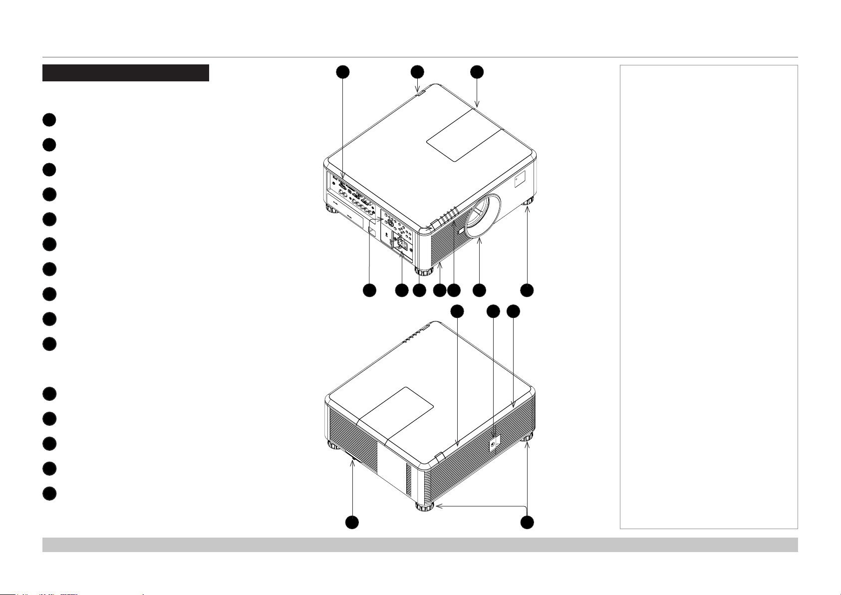
Front and rear views
Connection panel
1
Rear infrared window
2
Color wheel door
3
Control panel
4
Power switch and power connection
5
Front infrared window
6
Air inlet
7
Indicators
8
Lens mount
9
Adjustable foot
10
1
2
5 9
8376 104
131211
Notes
Lamp compartment with air outlets
11
Lamp compartment door
12
Air outlet
13
Air inlet and lter
14
Adjustable feet
15
Installation and Quick-Start Guide
14 15
Rev A February 2017
page 3
Page 10
Digital Projection E-Vision 6900 Series
CONNECTING THE POWER SUPPLY
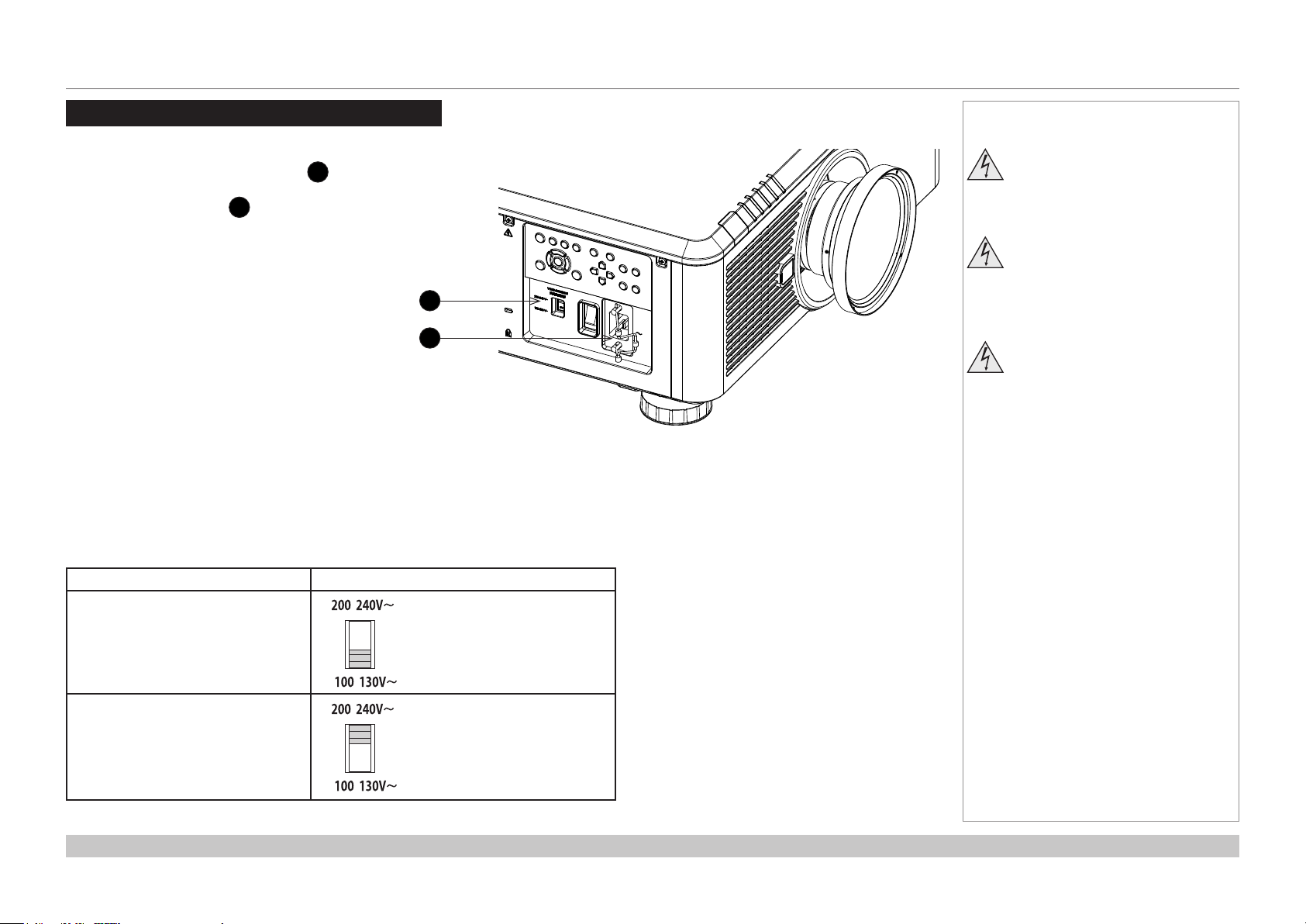
Connecting The Power Supply
Adjust the VOLTAGE SELECT switch 1 to
the required voltage, then rmly push the mains
connector into the socket 2.
1
2
Voltage selection
The VOLTAGE SELECT switch must be set to match the power supply you are using:
Notes
Use only the power cable
provided.
Ensure that the power outlet
includes a ground connection as
this equipment MUST be earthed.
Handle the power cable carefully
and avoid sharp bends. Do not
use a damaged power cable.
Voltage of power supply used Position of VOLTAGE SELECT switch
AC 100 - 130 V outlet
AC 200-240 V (single phase) outlet
Installation and Quick-Start Guide
Rev A February 2017
page 4
Page 11
Digital Projection E-Vision 6900 Series
REMOTE CONTROL
Remote Control
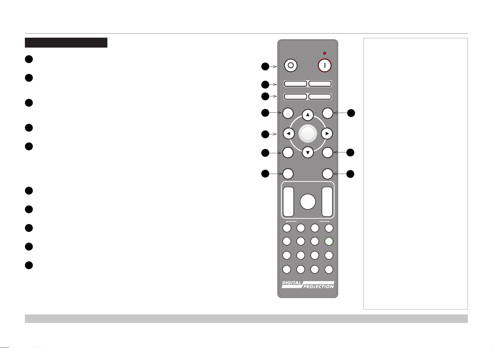
1
Power ON / OFF
Turns power on and off.
2
Pic Mute ON / OFF
Shows and hides the projected image.
When OFF, the light source is completely switched off and the screen is black.
2
OSD ON / OFF
Enable and disable screen timeout messages and control whether to show the OSD
during projection.
4
MENU
Access the OSD. If the OSD is open, press this button to go back to the previous menu.
5
Navigation (arrows and OK)
Navigate through the menus with the arrows, conrm your choice with OK.
In lens adjustment modes, the arrows are used to move, zoom or focus the lens. See 11
below.
In lens adjustment modes, or when the OSD is not showing, the OK button switches
between modes: Shift Adjustment and Zoom / Focus Adjustment.
6
EXIT
Go up one level in the OSD. When the top level is reached, press to close the OSD.
7
FREEZE
Freeze the current frame.
8
DEFAULT
When editing a parameter, press this button to restore the default value.
9
INFO
Access information about the projector.
10
RE-SYNC
Re-synchronise with the current input signal.
Notes
OFF ON
1
Pic Mute
2
3
4
5
6
7
OFF
OFF
MENU
EXIT INFO
FREEZE
FOCUS ZOOM
IN
OUT
USER PRESET
A B C D
HDMI2 DVI
HDMI1
21 3
BRI
CON GAMMA
DISPLAYPORT
HD-T 3GSDI
4 5 6
R G B ALL
VGA COMP1 COMP2
7 8 9 0
3D EYE PIP SWAP
ON
OSD
ON
DEFAULT
8
OK
9
RE-SYNC
10
LENS
IN
SHIFT
OUT
ALT
ALT
ADDR
TEST
continues on next page...
Installation and Quick-Start Guide
Rev A February 2017
page 5
Page 12
MENU
EXIT INFO
OK
OSD
OFF
ON
DEFAULT
Digital Projection E-Vision 6900 Series
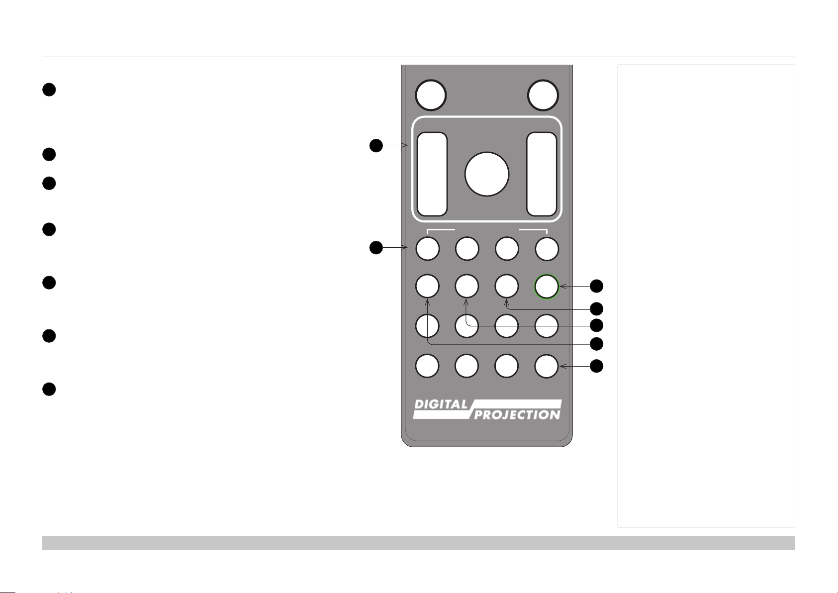
11
LENS adjustment
FOCUS IN / OUT: adjust focus.
SHIFT: press and hold this button, then use the Navigation arrow
buttons to move the lens.
ZOOM IN / OUT: adjust zoom.
12
USER PRESET A, B, C, D
This featrure is not supported.
13
ALT
14
Press and hold this button to access alternative functions for all
buttons with a green label.
DVI / GAMMA / numeric input 3
Select the DVI input.
Use with ALT to switch to the next Gamma value:
...1.0, 1.8, 2.0, 2.2, 2.35, 2.5...
15
HDMI 2 / CON / numeric input 2
Select the HDMI 1 input.
Use with ALT to bring up the Contrast control, then adjust the value
with the LEFT and RIGHT arrow buttons.
16
HDMI 1 / BRI / numeric input 1
Select the HDMI 1 input.
Use with ALT to bring up the Brightness control, then adjust the
value with the LEFT and RIGHT arrow buttons.
17
TEST / SWAP / numeric input 0
Show a test pattern. Press again to show the next test pattern:
...Off, White, Black, Red, Green, Blue, CheckerBoard,
CrossHatch, V Burst, H Burst, ColorBar...
The SWAP function is not supported.
REMOTE CONTROL
FREEZE
FOCUS ZOOM
11
12
IN
OUT
A B C D
HDMI1
BRI
DISPLAYPORT
4 5 6
R G B ALL
VGA COMP1 COMP2
7 8 9 0
3D EYE PIP SWAP
LENS
SHIFT
USER PRESET
HDMI2 DVI
21 3
CON GAMMA
HD-T 3GSDI
RE-SYNC
IN
OUT
ALT
ALT
ADDR
TEST
Notes
13
14
15
16
17
continues on next page...
Installation and Quick-Start Guide
Remote control
Rev A February 2017
page 6
Page 13
Pic Mute
OFF
ON
MENU
EXIT INFO
OK
LENS
FOCUS ZOOM
OSD
OFF
ON
DEFAULT
FREEZE
RE-SYNC
Digital Projection E-Vision 6900 Series
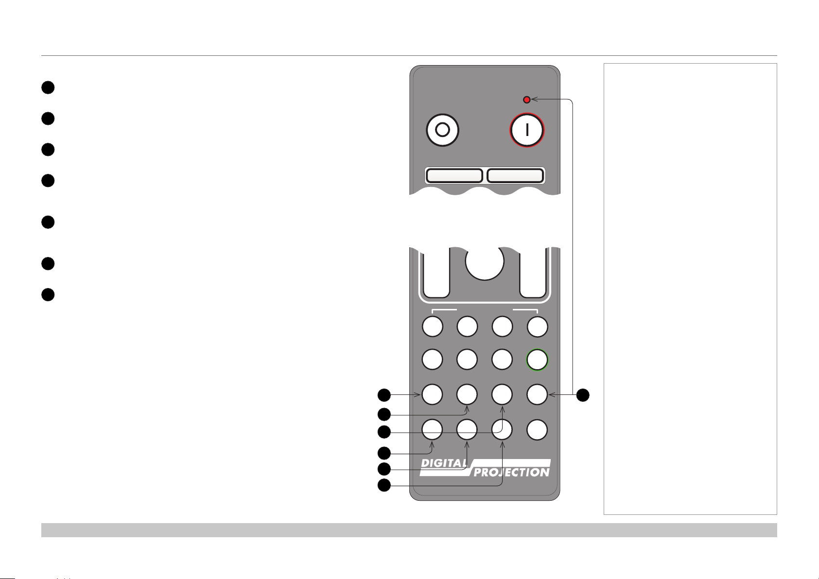
17
DISPLAYPORT / R / numeric input 4
18
HD-T / G / numeric input 5
DisplayPort is not supported.
Select the HDBaseT input.
19
3GSDI / B / numeric input 6
3G-SDI is not supported.
20
VGA / 3D / numeric input 7
Select the VGA input.
Use with ALT to toggle the 3D Format setting between Off and Auto.
21
COMP1 / EYE / numeric input 8
22
23
Select the Component 1 input.
Use with ALT to switch between left and right eye 3D dominance.
COMP2 / PIP / numeric input 9
Component 2 and PIP are not supported.
ADDR / ALL (with red indicator at the top)
Assign and unassign an IR remote address.
To assign an address:
1. Press and hold this button until the indicator starts ashing.
2. Release this button and while the indicator is still ashing, enter
a two-digit address using the numeric input buttons. The indicator
will ash three times quickly to conrm the change.
To unassign an address and return to the default address 00,
• Press and hold ALT and this button simultaneously until the
indicator ashes to conrm the change.
REMOTE CONTROL
OFF ON
Remote control top
IN
OUT
A B C D
HDMI1
BRI
DISPLAYPORT
17
18
19
20
21
22
4 5 6
R G B ALL
VGA COMP1 COMP2
7 8 9 0
3D EYE PIP SWAP
Pic Mute
OFF
OSD
SHIFT
USER PRESET
HDMI2 DVI
21 3
CON GAMMA
HD-T 3GSDI
Notes
ON
IN
OUT
ALT
ALT
ADDR
23
TEST
Installation and Quick-Start Guide
Remote control bottom
Rev A February 2017
page 7
Page 14
Digital Projection E-Vision 6900 Series
REMOTE CONTROL
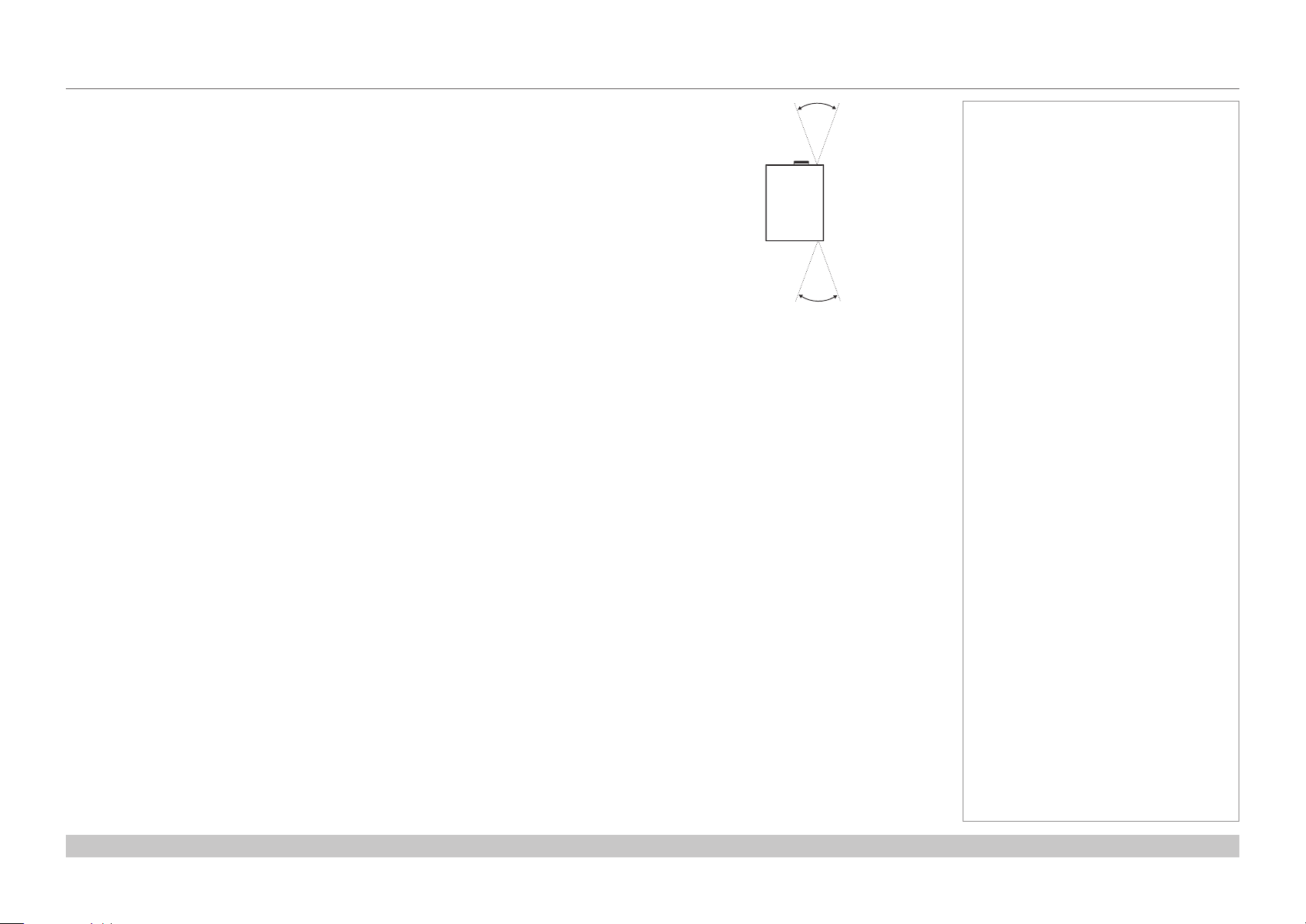
Infrared reception
The projector has infrared sensors at the front and back.
The angle of acceptance is 40°. Make sure that the remote control is within the angle of
acceptance when trying to control the projector.
40°
40°
Infrared reception
Notes
Installation and Quick-Start Guide
Rev A February 2017
page 8
Page 15
Digital Projection E-Vision 6900 Series
CONTROL PANEL
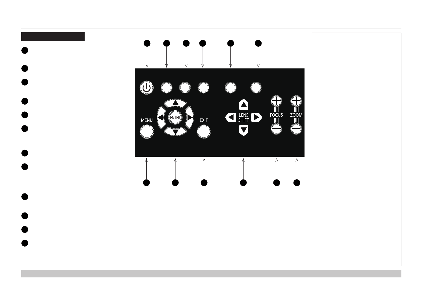
Control Panel
POWER
1
2
3
4
5
6
7
8
9
10
11
12
Switches the projector on and off
(STANDBY).
INPUT
Switches to the next input source.
AUTO SYNC
Re-synchronises with the current input
signal.
ASPECT
Changes the aspect ratio.
CENTER LENS
Centers the lens.
SHUTTER
Shows and hides the projected image.
When OFF, the light source is completely
switched off and the screen is black.
MENU
Displays and exits the OSD.
Arrow buttons & ENTER
Navigation buttons used to highlight menu
entries in the OSD.
Press ENTER to open or execute the
highlighted menu entry.
EXIT
Exits the current OSD page and enters the
level above.
LENS SHIFT arrow buttons
Each of these buttons moves the lens in the specied direction.
FOCUS plus and minus buttons
Used to move the focus in and out.
ZOOM plus and minus buttons
Used to zoom in and out.
1 2 3 4 5 6
POWER
7 8 9 10 11 12
INPUT
AUTO
SYNC
ASPECT
CENTER
LENS
SHUTTER
Notes
Installation and Quick-Start Guide
Rev A February 2017
page 9
Page 16
Digital Projection E-Vision 6900 Series
CONTROL PANEL
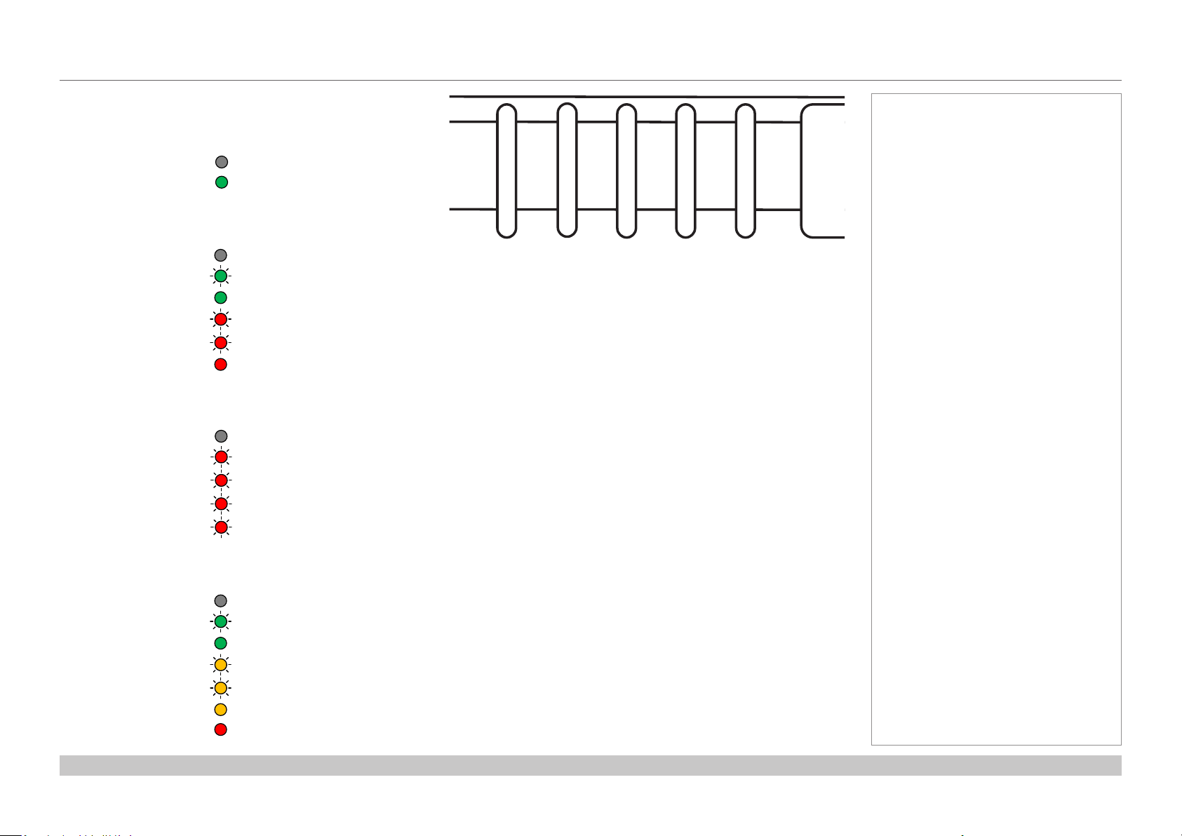
Indicators
SHUTTER
Behavior Meaning
Off The shutter is open.
Steady green The shutter is closed.
LAMP 2 / LAMP 1
Behavior Meaning
Off The lamp is switched off.
Flashing green The lamp is preparing to switch on.
Steady green The lamp is switched on.
One red ash, pause No lamp.
Six red ashes, pause The lamp failed to switch on.
Steady red The lamp is end-of-life.
STATUS
Behavior Meaning
Off No error.
One red ash, pause Cover error.
Two red ashes, pause Temperature error.
Three red ashes, pause System error.
Four red ashes, pause Fan error.
Notes
STATUSLAMP 1LAMP 2SHUTTER POWER
POWER
Behavior Meaning
Off The projector is switched off.
Flashing green The projector is warming up.
Steady green The projector is switched on.
Flashing amber The projector is cooling down.
One amber ash, pause Keypad Lock warning.
Steady amber The projector is in Network STANDBY mode (<3W).
Steady red The projector is in Eco STANDBY mode (<0.5W).
Installation and Quick-Start Guide
Rev A February 2017
page 10
Page 17
Digital Projection E-Vision 6900 Series
CHANGING THE LENS, LAMPS, FILTER AND COLOR WHEEL
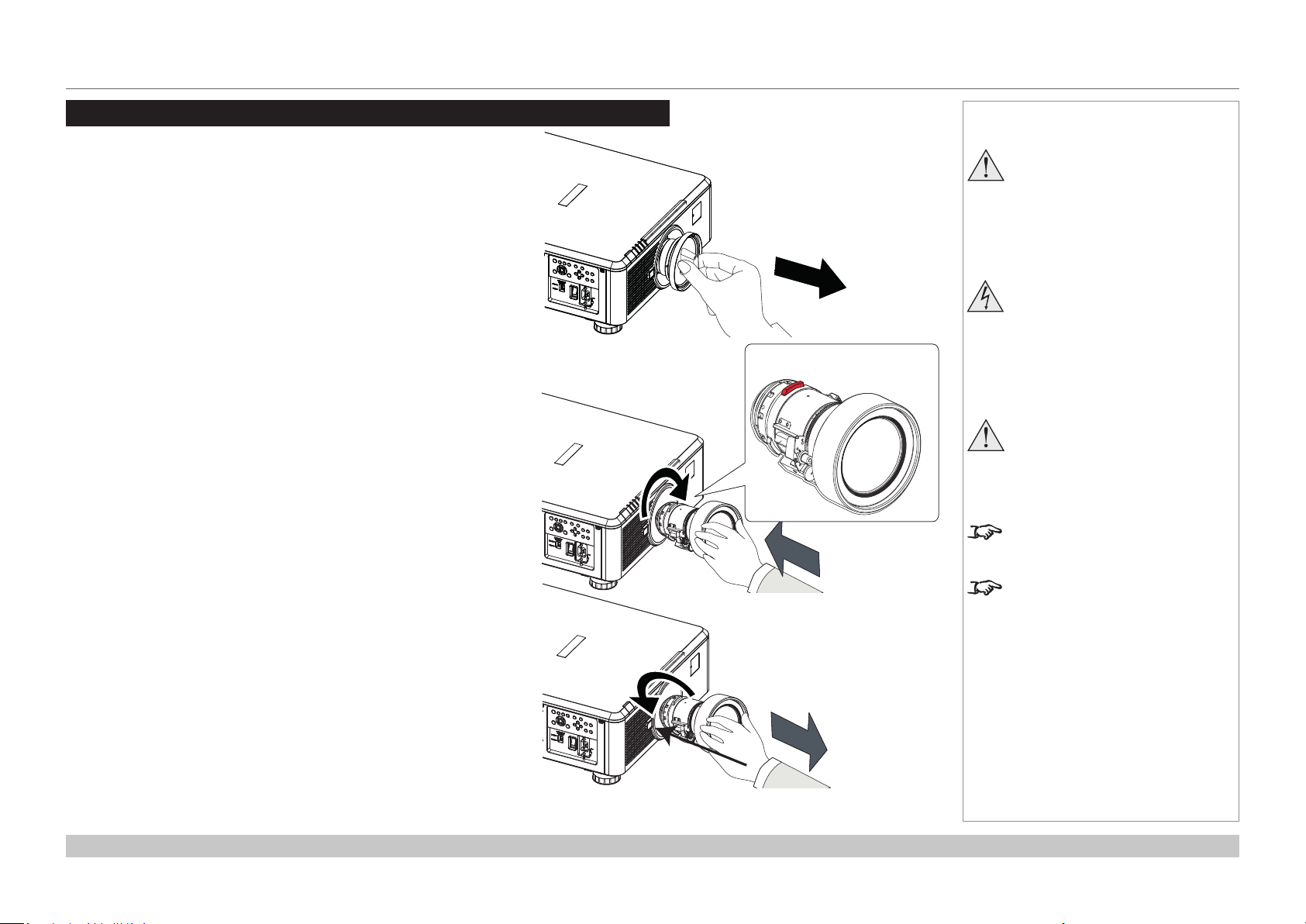
Changing The Lens, Lamps, Filter And Color Wheel
Inserting a new lens
1. Remove the front and rear lens caps.
2. Position the lens so that the labels are at the top, and gently insert it
all the way into the lens mount.
3. Push the lens in rmly and turn it clockwise until it clicks into place.
Notes
Always allow the lamp to cool for
5 minutes before:
- disconnecting the power
- moving the projector
Before changing the lens,
always make sure the projector
is switched off and fully
disconnected from its power
supply.
When changing the lens, avoid
using excessive force as this may
damage the equipment.
The lens is shipped separately.
Removing the lens
1. Push in the lens release lever, and turn the lens anti-clockwise.
2. Remove the lens..
Installation and Quick-Start Guide
Take care to preserve the original
lens packaging and protective caps
for future use.
Rev A February 2017
page 11
Page 18
Digital Projection E-Vision 6900 Series
CHANGING THE LENS, LAMPS, FILTER AND COLOR WHEEL
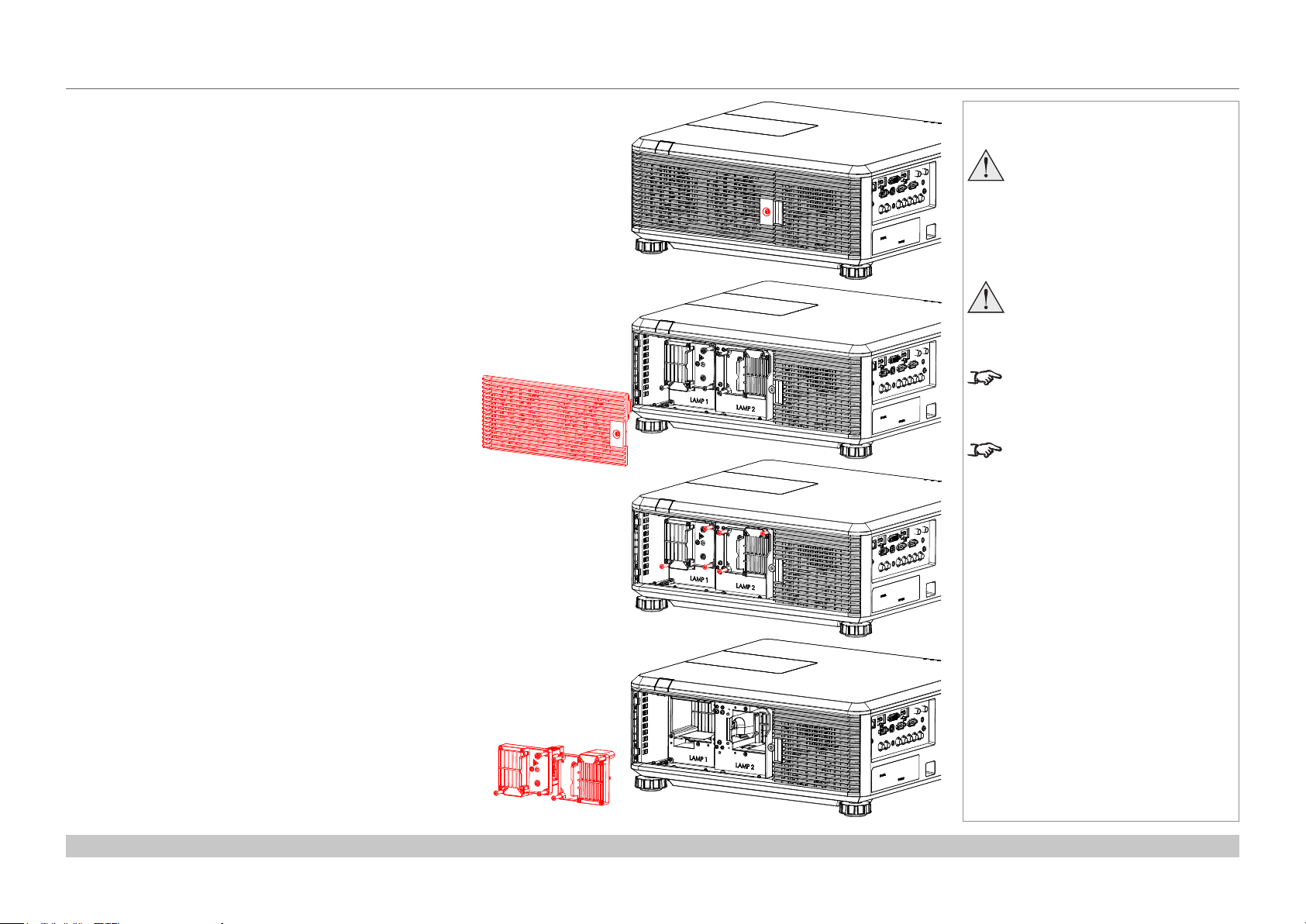
Changing the lamps
1. Unscrew the captive screw holding the lamp compartment
door.
2. Remove the door to reveal the lamp modules.
Notes
Always allow the lamp to cool for
5 minutes before:
- disconnecting the power
- moving the projector
The lamp must be changed only
by suitably qualied personnel.
The projector will shut down if the
cover is opened whilst in operation.
Theltersshouldbechangedatthe
same time as the lamp is changed.
3. Unscrew the three captive screws holding each lamp
module in its place.
4. Pull out the old lamp modules and insert the new ones.
5. Use the three captive screws on each module to hold it into
position, then replace the lamp compartment cover and
secure it with the screw.
Installation and Quick-Start Guide
Rev A February 2017
page 12
Page 19
Digital Projection E-Vision 6900 Series
CHANGING THE LENS, LAMPS, FILTER AND COLOR WHEEL
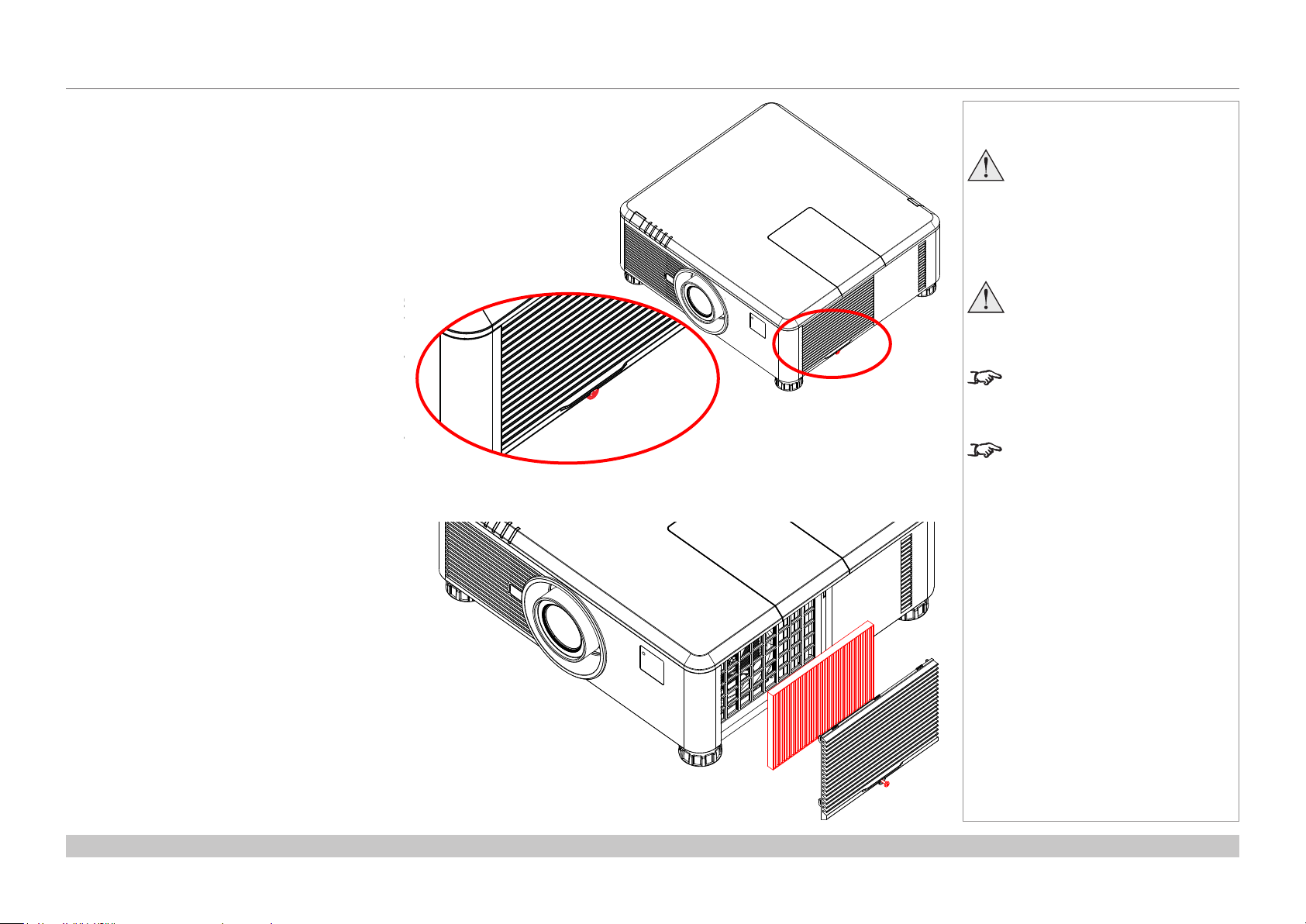
Changing the lter
1. Loosen the captive screw at the bottom of the
lter door.
Notes
Always allow the lamp to cool for
5 minutes before:
- disconnecting the power
- moving the projector
The lamp must be changed only
by suitably qualied personnel.
The projector will shut down if the
cover is opened whilst in operation.
Theltersshouldbechangedatthe
same time as the lamp is changed.
2. Remove the door and the lter as shown in the
illustration.
3. Replace the lter, then close the door and
tighten the screw to secure it in place.
Installation and Quick-Start Guide
Rev A February 2017
page 13
Page 20
Digital Projection E-Vision 6900 Series
CHANGING THE LENS, LAMPS, FILTER AND COLOR WHEEL
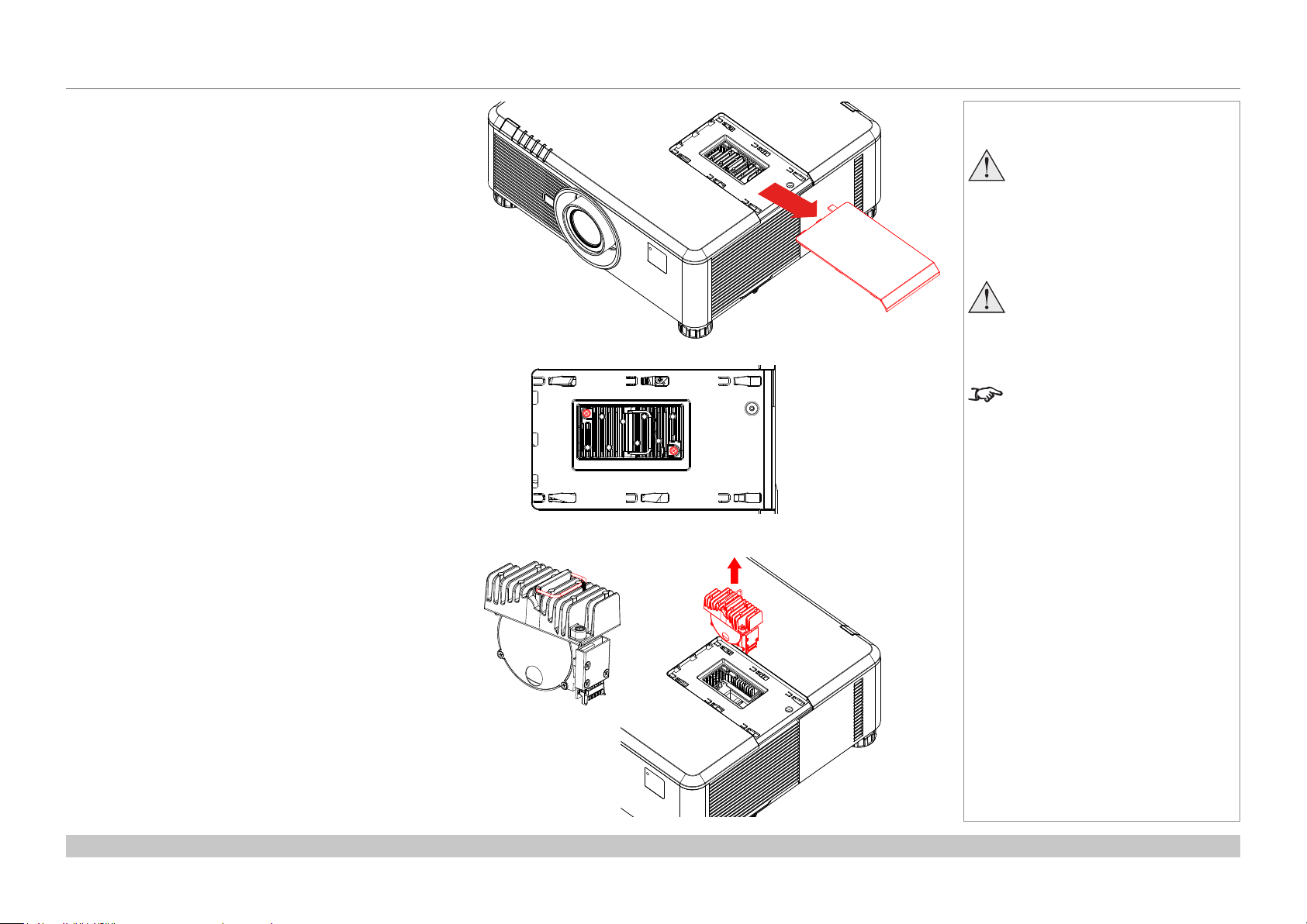
Changing the color wheel
1. Slide open the lamp compartment cover as shown in the
picture.
2. Unscrew the two captive screws securing the color wheel.
Notes
Always allow the lamp to cool for
5 minutes before:
- disconnecting the power
- moving the projector
The color wheel must be changed
only by suitably qualied
personnel.
The projector will shut down if the
cover is opened whilst in operation.
3. Lift and pull the color wheel handle to remove the color
wheel.
4. Insert a new color wheel, lower the handle, fasten the
screws and replace the lamp compartment cover.
Installation and Quick-Start Guide
Rev A February 2017
page 14
Page 21
Digital Projection E-Vision 6900 Series
POSITIONING THE SCREEN AND PROJECTOR
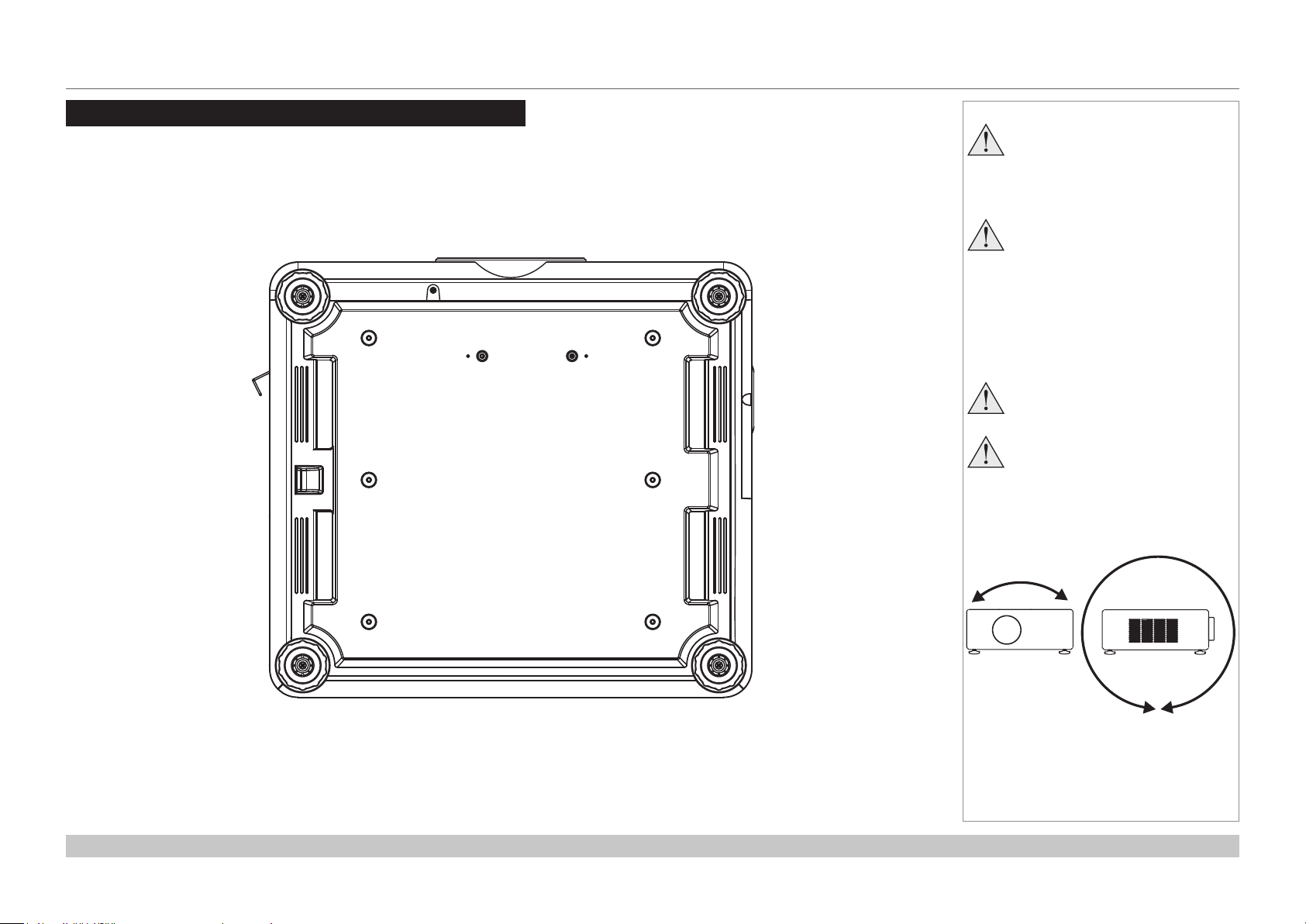
Positioning The Screen And Projector
1. Install the screen, ensuring that it is in the best position for viewing by your audience.
2. Mount the projector, ensuring that it is at a suitable distance from the screen for the image to ll the screen. Set the adjustable feet so that
the projector is level, and perpendicular to the screen.
Alternatively, six M4 bolts (max length 16 mm [0.6 in]) can be used to attach the projector to a ceiling mount (optional accessory,).
Notes
Always allow the lamp to cool for
5 minutes before:
- disconnecting the power
- moving the projector
Ensure that there is at least
50cm (20in) of space between the
ventilation outlets and any wall,
and 10cm (4in) on all other sides.
If ceiling mounting, ensure there
is 30cm (12in) of space between
the projector and ceiling.
Do not stack the projectors.
Do not tilt the projector more than
±10° from side to side when in
use, as this may cause serious
lamp failure, damage the lamp
module and cause extra cost on
replacement.
Location of the ceiling mount holes at the bottom of the projector
Installation and Quick-Start Guide
±10°
±360°
Rev A February 2017
page 15
Page 22
Digital Projection E-Vision 6900 Series
OPERATING THE PROJECTOR
Operating The Projector
Switching the projector on
• Connect the power cable between the mains supply and the projector. Switch on at the switch next to the power connector.
• Wait until the self-test has completed and the Power indicator on the projector control panel shows amber. The lamp will be off and the
projector will be in STANDBY mode.
• Press on the control panel or POWER ON on the remote control.
The Power indicator on the control panel will ash green for a few seconds whilst the lamp comes up to full brightness. When the
projector is ready for use, the Power indicator will show steady green.
Selecting an input signal or test pattern
Input signal
• Connect an image source to the projector. The signal should be automatically detected by the projector, and should be displayed within a
two or three seconds.
• If more than one signal is connected, then select the image you want to display:
• On the control panel, press INPUT to cycle through the inputs,
or
• on the remote control, press the button for the input of your choice,
or
• on any device, press MENU to show the OSD (On-screen DIsplay), then highlight Input, then press OK/ENTER to open the list of
inputs.
Notes
Before switching on the projector
for the rst time, make sure
the electric circuit is grounded.
Poor grounding may damage the
projector.
Always allow the lamp to cool for
5 minutes before:
- disconnecting the power
- moving the projector
For full details of how to connect an
image source to the projector, see
the Connection Guide.
Test pattern
To display a test pattern:
1. Press MENU to open the OSD. Use the UP and DOWN arrow buttons to highliught Test Pattern, then press OK/ENTER to open the list
of test patterns. Alternatively, on the remote control press TEST to open the same list.
2. Use the UP and DOWN arrow buttons to highlight the test pattern you wish to display and press OK/ENTER.
Installation and Quick-Start Guide
For full details of how to use the
controls and the menu system, see
the Operating Guide.
Rev A February 2017
page 16
Page 23

Digital Projection E-Vision 6900 Series
OPERATING THE PROJECTOR
Adjusting the lens
Zoom
• Use the ZOOM +/− buttons on the control panel or the ZOOM IN/OUT buttons on the remote control to adjust the lens so that the image
lls the screen.
Focus
• Use the FOCUS +/− buttons on the control panel or the FOCUS IN/OUT buttons on the remote control to adjust the lens until the image is
sharp.
Shift
• Use the LENS SHIFT arrow buttons on the control panel to adjust the position of the image,
or press the SHIFT button on the remote control then use the arrow buttons to adjust the position of the image.
Adjusting the image
Orientation
• Use the Orientation settings in the Setup menu.
Aspect ratio
• Press the ASPECT button on the control panel to cycle through all the available settings.
or
• use the Aspect Ratio setting in the Geometry menu.
Picture
• Open the Image menu, then use the sliders to adjust brightness, contract etc.
Notes
For full details of how to use the
controls and the menu system, see
the Operating Guide.
Installation and Quick-Start Guide
Rev A February 2017
page 17
Page 24
Digital Projection E-Vision 6900 Series
OPERATING THE PROJECTOR
Switching the projector off
• Press on the control panel or POWER OFF on the remote control, then press the button a second time within 5 seconds to conrm.
The lamp will go off, and the Power indicator on the control panel will ash amber for a few seconds whilst the lamp cools. The Power
indicator on the control panel will then show amber and the projector will be in Standby mode.
• Switch the projector off completely from the switch next to the power connector. Disconnect the power cable from the projector.
Notes
Always allow the lamp to cool for
5 minutes before:
- disconnecting the power
- moving the projector
Installation and Quick-Start Guide
Rev A February 2017
page 18
Page 25

E-Vision 6900 Series
High Brightness Digital Video Projector
4
CONNECTION GUIDE
Rev A February 2017
Page 26

Digital Projection E-Vision 6900 Series
IN THIS GUIDE
IN THIS GUIDE
Signal Inputs And Outputs ............................................................................. 21
Control Connections ........................................................................................ 22
Connection Guide
Rev A February 2017
Page 27
Digital Projection E-Vision 6900 Series
SIGNAL INPUTS AND OUTPUTS
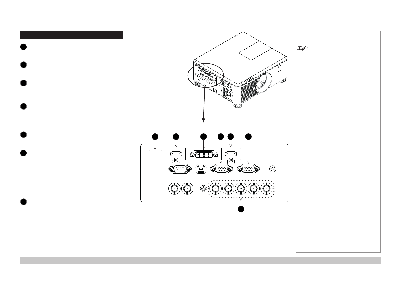
Signal Inputs And Outputs
HDBaseT/LAN
1
2
3
4
5
6
7
Receives digital signal from HDBaseT-compliant
devices.
HDMI II
This HDMI 1.4 input supports HDCP 1.1 and DVI
1.0.
DVI-D
This input can receive digital (DVI-D) signal from a
compatible source.
Supports HDCP.
Monitor Out
Connect an analog monitor cable (VGA) to the 15-
pin D-type connector.
The connected monitor will display signal received
via the VGA input.
HDMI I
This HDMI 1.4 input supports HDCP 1.1 and DVI
1.0.
VGA
This input receives analog signals from a
computer.
When using this input, it is best to use a fully
wired VGA cable to connect the source to the
projector. This will allow the source to determine
the projector’s capabilities via DDC and show an
optimized image. Such cables can be identied as
they have a blue connector shell.
Component
Connect a set of RGsB, RGBHV or YCbCr cables
to the BNC connectors.
1 2 3 5 6
4
7
Notes
For a complete listing of pin
congurationsforallsignaland
control connectors, see Wiring
Details later in this Guide.
Connection Guide
Rev A February 2017
page 21
Page 28
Digital Projection E-Vision 6900 Series
CONTROL CONNECTIONS
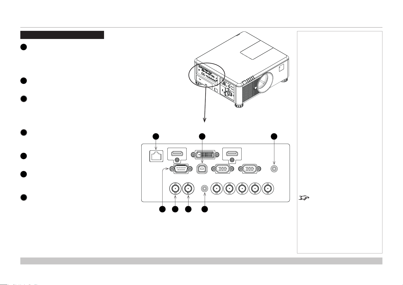
Control Connections
HDBaseT/LAN
1
Receives digital signal from HDBaseT-compliant
devices.
All of the projector’s features can be controlled via
a LAN connection, using commands described in
the Remote Communications Guide.
Service
2
3
4
5
6
The USB Service port is used for rmware
updates only.
Screen Trigger
The Trigger output can be connected to an
electrically operated screen, automatically
deploying the screen when the projector is
switched on, and retracting the screen when the
projector is switched to standby.
RS-232
All of the projector’s features can be controlled via
a serial connection, using commands described in
the Remote Communications Guide.
3D Sync Out
Connect to a Z Screen or 3D IR emitter as
appropriate.
3D Sync In
Connect the 3D sync from your graphics card or
server.
1 3
2
Notes
Wired Remote
7
The remote control can be connected using a
standard 3.5 mm mini jack cable (tip-ring-sleeve,
or TRS).
Connection Guide
Plugging in the remote control cable
will disable infrared transmission.
5 6 74
Rev A February 2017
page 22
Page 29

E-Vision 6900 Series
High Brightness Digital Video Projector
4
OPERATING GUIDE
Rev A February 2017
Page 30

Digital Projection E-Vision 6900 Series
IN THIS GUIDE
IN THIS GUIDE
Using The Projector ......................................................................................... 25
Main menu .................................................................................................................25
Lens menu .................................................................................................................26
Lens Memory ..................................................................................................................27
Image menu ...............................................................................................................28
Image Mode ....................................................................................................................28
Brightness and Contrast .................................................................................................28
Gamma ...........................................................................................................................29
Dynamic Black ................................................................................................................29
Saturation, Hue, Sharpness and Noise Reduction .........................................................29
Position and Phase .........................................................................................................30
Resync ............................................................................................................................30
Color menu ................................................................................................................31
Color Space ....................................................................................................................31
Color Temperature ..........................................................................................................32
Trim .................................................................................................................................33
Hue / Saturation / Gain ...................................................................................................33
Geometry menu .........................................................................................................35
Aspect Ratio ....................................................................................................................35
Keystone .........................................................................................................................36
Corner Adjustment ..........................................................................................................38
Overscan .........................................................................................................................39
Setup menu ................................................................................................................44
Network ...........................................................................................................................45
RS232 .............................................................................................................................45
Security ...........................................................................................................................46
Filter ................................................................................................................................46
EDID Mode .....................................................................................................................47
Projector ID Control ........................................................................................................47
System ............................................................................................................................48
Information menu ......................................................................................................49
Source information ..........................................................................................................49
Factory Reset ..................................................................................................................49
Menu Map............................................................................................................. 50
3D menu .....................................................................................................................40
The 3D Swap setting explained ......................................................................................40
3D types ..........................................................................................................................41
Frame rate multiplication in 3D images ...........................................................................42
Lamps menu ..............................................................................................................43
Operating Guide
Rev A February 2017
Page 31

Digital Projection E-Vision 6900 Series
USING THE PROJECTOR
Using The Projector
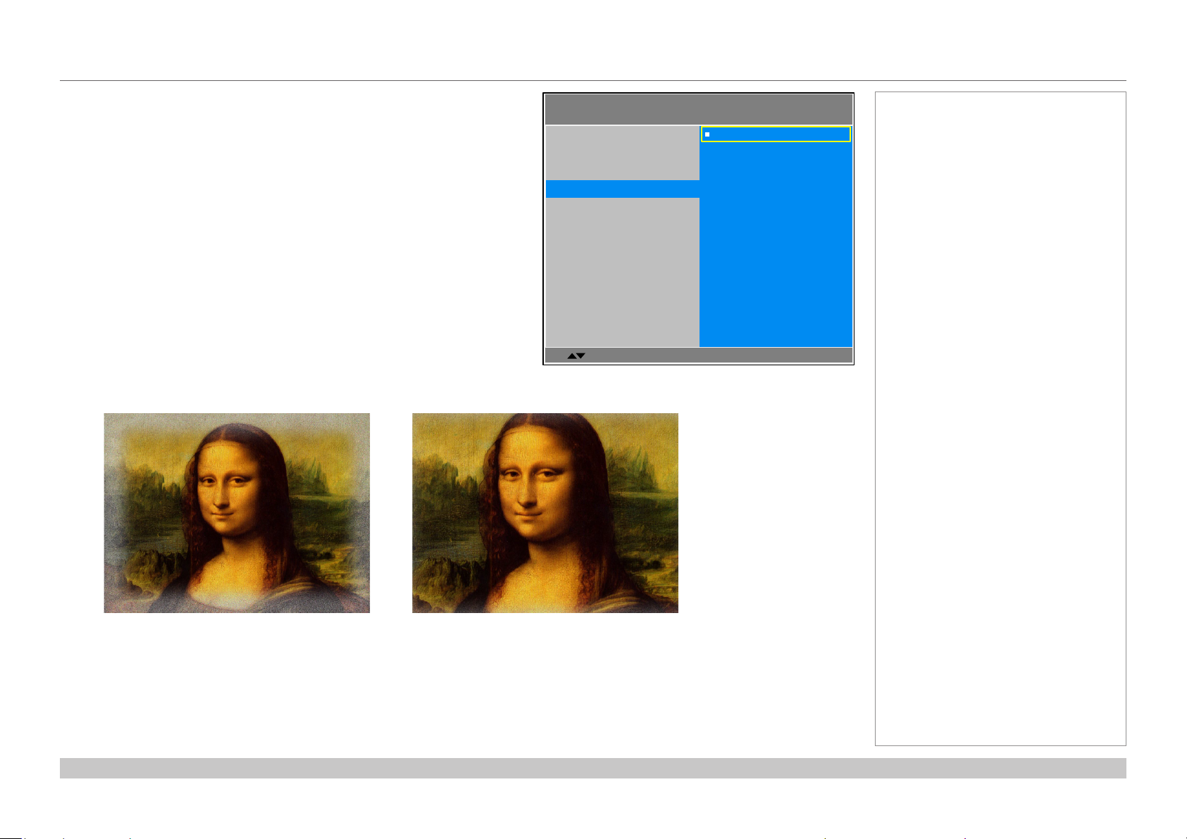
Main menu
• Input
Press ENTER to open the list of available inputs.
Use the UP and DOWN arrow buttons to select an input from the list, then
press ENTER to conrm your choice.
Press MENU to return to the main menu.
• Test Pattern
Choose from:
...Off, White, Black, Red, Green, Blue, Checkerboard, Crosshatch, V Burst,
H Burst, Color Bar, H Ramp...
Use the LEFT and RIGHT arrow buttons to switch between values.
• Lens, Image, Color, Geometry, 3D, Lamps, Setup and Information
Press ENTER to open these menus and access various settings.
E-Vision 6900
Input
Test Pattern
Lens
Image
Color
Geometry
3D
Lamps
Setup
Information
Select Item
E-Vision 6900
Input
Test Pattern
Lens
Image
Color
Geometry
3D
Lamps
Setup
Information
[Enter] Submenu
[Menu] Exit
HDMI I
HDMI II
DVI-D
VGA
Component
HDBaseT
HDMI
Off
8
8
8
8
8
8
8
8
Notes
If no input is connected, the Image
menu will be unavailable.
Some settings are associated with
the current input and the value of
the Image Mode setting (Bright,
Presentation or Video). The
projector automatically stores values
of such settings to reuse when an
Input / Image Mode combination
is selected again. For example, if
you increase the Contrast value
while on the DVI-D input with Image
Mode set to Bright, the next time
you use the DVI-D input with Image
Mode set to Bright, the projector
will automatically set the same
Contrast value.
Settings NOT associated with an
Input / Image Mode combination
are called global settings and are
indicated with a globe icon
Menu Map further in this guide.
in the
Operating Guide
Select Item
[Enter] Execute
[RETURN] Back
Rev A February 2017
page 25
Page 32

Digital Projection E-Vision 6900 Series
USING THE PROJECTOR
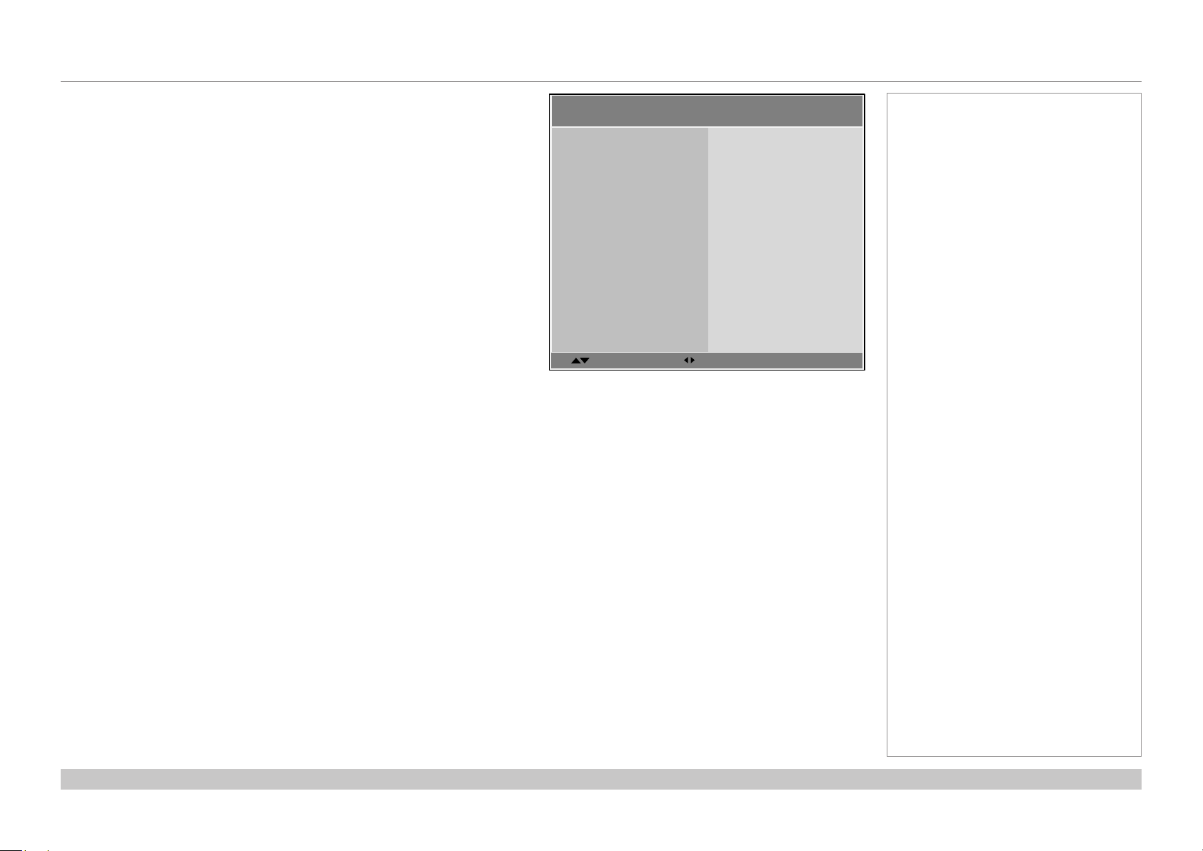
Lens menu
• Lens Lock
• Lens Control
Lens Control operates in Zoom/Focus and Shift mode.
When in Zoom/Focus mode:
• Use the UP and DOWN arrow buttons to adjust Zoom.
• Use the LEFT and RIGHT arrow buttons to adjust Focus.
When in Shift mode, use the arrow buttons to adjust Shift.
Press ENTER to switch between Shift and Zoom/Focus mode.
• Lens Type
Choose UST or non-UST lens.
• Center Lens
• Lens Memory
Open a submenu to save, load or clear a lens preset.
Lens >>
Lens Lock
Lens Control
Lens Type
Center Lens
Lens Memory
Save Memory
Load Memory
Clear Memory
Select Item
Adjust
Lens Control
Zoom
Focus
Notes
Off
8
non-UST lens
Execute
8
8
8
[RETURN] Back
See Lens Memory further in this
guide.
Operating Guide
Enter to Shift
Lens Control
Shift V
Shift H
Enter to Zoom/Focus
Rev A February 2017
page 26
Page 33

Digital Projection E-Vision 6900 Series
USING THE PROJECTOR
Lens menu continued from previous page
Lens Memory
These menus allows you to load, save and delete up to ten lens presets,
containing position, zoom, focus and shift adjustment information.
For example, if using different screen sizes and aspect ratios, you can save zoom,
focus and positioning for each screen size and aspect ratio in a dedicated preset.
Use Clear Memory to delete a memory preset if you need to save a new
combination of lens settings in its place. Overwriting a saved memory preset is not
possible.
Lens >> Load Memory
Memory 1
Memory 2
Memory 3
Memory 4
Memory 5
Memory 6
Memory 7
Memory 8
Memory 9
Memory 10
8
8
8
8
8
8
8
8
8
8
Lens >> Save Memory
Memory 1
Memory 2
Memory 3
Memory 4
Memory 5
Memory 6
Memory 7
Memory 8
Memory 9
Memory 10
Select Item
Lens >> Clear Memory
Memory 1
Memory 2
Memory 3
Memory 4
Memory 5
Memory 6
Memory 7
Memory 8
Memory 9
Memory 10
[Enter] Submenu
Notes
8
8
8
8
8
8
8
8
8
8
[Menu] Exit
8
8
8
8
8
8
8
8
8
8
Operating Guide
Select Item
[Enter] Submenu
[Menu] Exit
Select Item
[Enter] Submenu
[Menu] Exit
Rev A February 2017
page 27
Page 34

Digital Projection E-Vision 6900 Series
USING THE PROJECTOR
Image menu
Image Mode
Choose from Bright, Presentation and Video.
Press ENTER to open the list.
Use the UP and DOWN arrow buttons to select an image mode from the list,
then press ENTER to conrm your choice.
Press MENU to return to the main menu.
Brightness and Contrast
Highlight the setting you wish to edit, and then press the LEFT or RIGHT
arrow button to open the slider.
Use the LEFT and RIGHT arrow buttons to adjust the slider.
Press MENU to close the slider.
Image >>
Image Mode
Brightness
Contrast
Gamma
Dynamic Black
Saturation
Hue
Sharpness
Noise Reduction
Position And Phase
Resync
Select Item
[Enter] Execute
Bright
Presentation
Video
[RETURN] Back
Image >>
Image Mode
Brightness
Contrast
Gamma
Dynamic Black
Saturation
Hue
Sharpness
Noise Reduction
Position And Phase
Resync Execute
Bright
100
100
2.2
Off
100
100
8
Notes
15
0
Operating Guide
Select Item
Brightness
Adjust
[RETURN] Back
100
Rev A February 2017
page 28
Page 35

Digital Projection E-Vision 6900 Series
USING THE PROJECTOR
Image menu continued from previous page
Gamma
Choose a de-gamma curve from 1.0, 1.8, 2.0, 2.2, 2.35, 2.5 and S Curve.
Used correctly, the Gamma setting can improve contrast while maintaining good
details for blacks and whites.
If excess ambient light washes out the image and it is difcult to see details in dark
areas, lower the Gamma setting to compensate. This improves contrast while
maintaining good details for blacks. Conversely, if the image is washed out and
unnatural, with excessive detail in black areas, increase the setting.
Dynamic Black
Set to On to allow for increased contrast in darker scenes by modulating the light
source.
Image >>
Image Mode
Brightness
Contrast
Gamma
Dynamic Black
Saturation
Hue
Sharpness
Noise Reduction
Position And Phase
Resync
Select Item
[Enter] Execute
Notes
1.0
1.8
2.0
2.2
2.35
2.5
[RETURN] Back
Saturation, Hue, Sharpness and Noise Reduction
Highlight the setting you wish to edit, and then press ENTER, or the LEFT or
RIGHT arrow button to open the slider.
Use the LEFT and RIGHT arrow buttons to adjust the slider.
Press MENU to close the slider.
Operating Guide
Noise Reduction
0
Saturation and Hue are only
accessible if the projector is
connected to a Component input
source.
Rev A February 2017
page 29
Page 36

Digital Projection E-Vision 6900 Series
USING THE PROJECTOR
Image menu continued from previous page
Position and Phase
Press ENTER to open a submenu.
• VGA Setup
H Total, H Start, H Phase, V Start
Adjust these settings as required to suit the incoming image.
• Digital Alignment
Digital Zoom, Digital Pan, Digital Scan
Select a digital alignment control.
Reset
Press ENTER to reset all Digital Alignment settings to zero.
• H/V Alignment
H Zoom, V Zoom, H Shift, V Shift
Select an alignment control.
Reset
Press ENTER to reset all H/V Alignment settings to zero.
Highlight the setting you wish to edit, and then press ENTER, or the LEFT or
RIGHT arrow button to open the slider.
Use the LEFT and RIGHT arrow buttons to adjust the slider.
Press MENU to close the slider.
Resync
Press ENTER to force the projector to resynchronize with the current input.
Image >> Position And Phase
VGA Setup
Digital Alignment
H/V Alignment
Select Item
Image >>
Image Mode
Brightness
Contrast
Gamma
Dynamic Black
Saturation
Hue
Sharpness
Noise Reduction
Position And Phase
Resync Execute
[Enter] Submenu
[RETURN] Back
8
8
8
Bright
100
100
2.2
Off
100
100
8
Notes
VGA Setup is only accessible if the
projector is connected to a VGA or
Comnponent input source.
Digital Pan and Digital Scan will
only work if Digital Zoom is greater
than zero.
H Shift will only work if the image
has been reduced horizontally using
H Zoom. Likewise, V Shift will
only work once V Zoom has been
applied.
15
0
Operating Guide
Select Item
[Enter] Execute
[RETURN] Back
Rev A February 2017
page 30
Page 37

Digital Projection E-Vision 6900 Series
USING THE PROJECTOR
Color menu
Color Space
In most cases, the Auto setting determines the correct colorspace to use. If it
does not, you can choose a specic colorspace:
Choose from Auto, YPbPr, YCbCr, RGB-PC and RGB-Video.
Color >>
Color Space
Color Temperature
Trim
Hue / Saturation / Gain
Select Item
Color >>
Color Space
Color Temperature
Trim
Hue / Saturation / Gain
Adjust
Notes
Auto
6500K
8
8
[Menu] Exit
Auto
YPbPr
YCbCr
RGB-PC
RGB-Video
Operating Guide
Select Item
[Enter] Execute
[RETURN] Back
Rev A February 2017
page 31
Page 38

Digital Projection E-Vision 6900 Series
USING THE PROJECTOR
Color menu continued from previous page
Color Temperature
Choose a value from 5500K (warmer) to 9300K (cooler) or Native (no
correction).
Color >>
Color Space
Color Temperature
Trim
Hue / Saturation / Gain
Select Item
[Enter] Execute
Notes
Native
5500K
6500K
7800K
9300K
[RETURN] Back
Operating Guide
Rev A February 2017
page 32
Page 39

Digital Projection E-Vision 6900 Series
USING THE PROJECTOR
Color menu continued from previous page
Trim
Adjust the RGB lift and gain settings to improve the color balance of the projected
image.
Highlight the setting you wish to edit, and then either press ENTER to access it, or
use the LEFT and RIGHT arrow buttons to switch between values.
Hue / Saturation / Gain
Press ENTER to open a submenu, then use the LEFT and RIGHT arrow
buttons to move the sliders.
Hue
Adjust hue of the main color as shown below:
Main color Hue
R Magenta
G Yellow
B Cyan
C Green
M Blue
Y Red
Yellow
Cyan
Magenta
Blue
Red
Green
Color >> Trim
Red Lift
Green Lift
Blue Lift
Red Gain
Green Gain
Blue Gain
Select Item
Color >> Hue / Saturation / Gain
Red
Green
Blue
Cyan
Magenta
Yellow
White
Adjust
Notes
100
100
100
100
100
100
[RETURN] Back
8
8
8
8
8
8
8
Saturation
When you adjust the saturation of the main color, the selected color becomes
lighter or thicker.
Gain
When you adjust the gain of the main color, the selected color becomes brighter
or darker.
Operating Guide
Select Item
[Enter] Submenu
[RETURN] Back
Rev A February 2017
page 33
Page 40

Digital Projection E-Vision 6900 Series
USING THE PROJECTOR
Color menu continued from previous page
Hue, Saturation and Gain explained
The levels of hue, saturation and gain change
the color values in the following ways:
1
Hue
Species the position of each color
(red, yellow, green, cyan, blue and
magenta) relative to its neighboring
colors.
2
Saturation
Species the level of white in each
color (i.e. how “pale” each color is).
3
Gain
Controls the amount of light that goes
into each color, i.e. the lowest gain
would produce black.
MAGENTA
RED
WHITE
CYAN
1
YELLOW
GREENBLUE
Notes
2
RED
BLACK
3
Operating Guide
Rev A February 2017
page 34
Page 41

Digital Projection E-Vision 6900 Series
USING THE PROJECTOR
Geometry menu
This menu allows you to compensate for image distortions caused by an unusual
projection angle or irregular screen surface.
Aspect Ratio
Choose from:
• 5:4
• 4:3
• 16:10
• 16:9
• 1.88:1
• 2.35:1
• TheaterScope
• Source
• Unscaled
To change the aspect ratio:
1. From the Main menu, open Aspect Ratio.
2. From the list on the right, select a new aspect ratio and press
ENTER.
Geometry >>
Aspect Ratio
Keystone
Corner Adjustment
Overscan
Select Item
Geometry >>
Aspect Ratio
H Keystone
V Keystone
Overscan
Select Item
Adjust
[Enter] Execute
Notes
Source
8
8
Off
[EXIT] Back
5:4
4:3
16:10
16:9
1.88:1
2.35:1
Letterbox
Source
Unscaled
[RETURN] Back
Operating Guide
Rev A February 2017
page 35
Page 42

Digital Projection E-Vision 6900 Series
USING THE PROJECTOR
Geometry menu continued from previous page
Keystone
Use the H Keystone and V Keystone settings to compensate for any distortion
caused by the projector being in a different horizontal or vertical plane to the
screen.
Highlight the setting you wish to edit, and then press the LEFT or RIGHT
arrow button to open the slider.
Use the LEFT and RIGHT arrow buttons to adjust the slider.
Press MENU to close the slider.
Keystone example
1
The projector is positioned at an angle
2
The resulting image is distorted
3
The image is corrected when V Keystone is applied
Geometry >> Keystone
H Keystone 0
V Keystone
Reset
H Keystone
V Keystone
Select Item
Adjust
Execute
[EXIT] Back
Notes
0
0
0
1 2 3
Operating Guide
Rev A February 2017
page 36
Page 43

Digital Projection E-Vision 6900 Series
USING THE PROJECTOR
Geometry menu continued from previous page
Keystone settings
1
Projector to the left
The projector is positioned
to the left of the screen.
To correct, apply a positive
H Keystone value using
the RIGHT arrow button.
2
Projector to the right
The projector is positioned
to the right of the screen.
To correct, apply a negative
H Keystone value using
the LEFT arrow button.
3
Projector high
The projector is positioned
above the screen at a
downward angle.
To correct, apply a negative
V Keystone value using
the LEFT arrow button.
4
Projector low
The projector is positioned
below the screen at an
upward angle.
To correct, apply a positive
V Keystone value using
the RIGHT arrow button.
Notes
1
2
5
Projector straight
The projector is directly
opposite the screen at a
right angle both horizontally
and vertically.
No correction is needed.
Operating Guide
4
53
Horizontal and vertical keystone corrections
Rev A February 2017
page 37
Page 44

Digital Projection E-Vision 6900 Series
USING THE PROJECTOR
Geometry menu continued from previous page
Corner Adjustment
Use the arrow buttons to highlight the corner you wish to edit.
Press ENTER to enter edit mode, then use the arrows to change H and V values.
Reset the currently highlighted corner by oressing and holding ENTER for two
seconds.
Exit edit mode with EXIT.
H: 0 / V: 0
[EXIT] Back
Corner Adjustment
Scroll
Corner Adjustment
H: 0
V: 0
Notes
[ENTER] Submenu
Operating Guide
[EXIT] Back
Adjust
[ENTER] Reset: 2 Seconds
Rev A February 2017
page 38
Page 45
Digital Projection E-Vision 6900 Series
USING THE PROJECTOR
Geometry menu continued from previous page
Overscan
Set to On to compensate for noisy or badly dened image edges.
Geometry >>
Aspect Ratio
Keystone
Corner Adjustment
Overscan
Select Item
[ENTER] Execute
Notes
Off
On
[EXIT] Back
Operating Guide
Image with noisy edges Overscanned image
Rev A February 2017
page 39
Page 46

Digital Projection E-Vision 6900 Series
USING THE PROJECTOR
3D menu
Use this menu to enable, disable and set up 3D input, as follows:
• 3D Format — Off, Auto, Side by Side, Top and Bottom and
Frame Sequential.
• DLP Link — On (if you are using 3D glasses that can utilise the
DLP Link® signal embedded in the image) and Off
• Eye Swap — Normal and Reverse (set to Rever se if the left- and
right-eye images are displayed in the wrong order)
• 3D 24Hz Display — set to 96Hz or 144Hz depending on the
source. This setting is disabled unless a 24Hz 3D input is detected.
• Sync Reference — set to Internal or External as required.
• Sync Delay — this setting is only available if Sync Reference is
set to External.
Set a value between 0 and 100 ms.
The 3D Swap setting explained
The outgoing 3D frames are in pairs - the dominant frame being
presented rst. You can determine which frame should be the dominant
one.
By convention the default setting is Left.
3D >>
3D Format
DLP- Link
Eye Swap
3D 24Hz Display
Sync Reference Internal
Sync Delay 0
Select Item
Dominance Left
LEFT 1 RIGHT 1 LEFT 2 RIGHT 2 LEFT 3 RIGHT 3
Dominance Right
Adjust
Normal
[EXIT] Back
LEFT 3RIGHT 1 LEFT 1 RIGHT 2 LEFT 2 RIGHT 3
Off
Off
144 Hz
Notes
If 3D Format is set to Off, or if
no 3D signal is detected in Auto
mode, the other 3D settings will be
unavailable.
Frame Sequential is supported on
the DVI input only.
3D video is only possible on the
HDMI, HDBaseT and DVI inputs.
The Frame Packing format is
automatically detected by the
projector.
See also 3D types further in this
guide.
Operating Guide
Rev A February 2017
page 40
Page 47

Digital Projection E-Vision 6900 Series
USING THE PROJECTOR
3D menu continued from previous page
3D types
In most situations you can use the Auto setting to have the projector automatically detect the format.
Otherwise, consider the notes below to help you set up the 3D input manually.
The following 3D formats are supported:
• Frame Packing
This format will be detected, re-synchronised, frame-multiplied and displayed at 144 Hz with the left eye /
right eye dominance automatically extracted from the video data.
• Top and Bottom
Sets the projector to reformat the video frames and map them to the display with the left eye / right eye
dominance automatically extracted from the video data.
• Side by Side (Half): interlaced and progressive, 50 and 60Hz
The side-by-side image will be de-interlaced (if appropriate), resized and then sequentially displayed at
100 or 120 Hz. The left eye / right eye dominance will be automatically extracted from the video data.
• Frame Sequential
An example of Frame Sequential would be 60Hz (30 frames per eye in Left-Right sequence (L1, R1,
L2, R2…) with 2x Frame Rate Multiplication, resulting in a displayed sequence at 120 Hz (L1, R1, L1,
R1, L2, R2, L2, R2…). For sequential 3D, the projector will generate an output sync, but it may then be
necessary to manually reset the dominance each time the player is started.
Notes
L
R
Frame Packing
L
R
Top-and-Bottom
L R
Side-by-Side (Half)
Operating Guide
L R L R
Frame Sequential
Rev A February 2017
page 41
Page 48

Digital Projection E-Vision 6900 Series
USING THE PROJECTOR
3D menu continued from previous page
Frame rate multiplication in 3D images
When displaying a low frame rate 3D video, the projector
multiplies the frame rate to obtain a icker-free image. For
example, a 60Hz frame rate is doubled to 120 Hz, or a 48 Hz
frame rate is tripled to 144 Hz.
Frame rate multiplication is an automatic process. It occurs in
the background and cannot be modied by the user.
IN
OUT
L1
R1 L3
R1
L2 R2
L1L1R1 R2L2 L3R2
x2 example
L2
Notes
Operating Guide
Rev A February 2017
page 42
Page 49

Digital Projection E-Vision 6900 Series
USING THE PROJECTOR
Lamps menu
• Lamp Mode
Choose from Auto 1, Dual, Lamp 1 and Lamp 2.
• Power Mode
Eco will automatically set the lamp power to 80%. Normal will set the power
to 92%.Set to Custom if you wish to adjust the power manually, from 80% to
100%.
• Custom Power Level
Use the LEFT and RIGHT arrow buttons to set lamp power. This setting is
only available if Power Mode is set to Custom.
• High Altitude
On increases the fan speed to compensate for reduced air density at high
altitude.
The following menu items show information only:
• Lamp 1 Status, Lamp 2 Status
• Lamp 1 Time, Lamp 2 Time
• Lamp 1 Life Remaining, Lamp 2 Life Remaining
Lamps >>
Lamp Mode
Power Mode
Custom Power Level
High Altitude Off
Lamp 1 Status
Lamp 2 Status
Lamp 1 Time
Lamp 2 Time
Lamp 1 Life Remaining
Lamp 2 Life Remaining
Select Item
On
On
00031 [H]
00015 [H]
98%
99%
Adjust
[RETURN] Back
Dual
Normal
-----
Notes
Operating Guide
Rev A February 2017
page 43
Page 50
Digital Projection E-Vision 6900 Series
USING THE PROJECTOR
Setup menu
• Orientation
Choose from Desktop Front, Desktop Rear, Ceiling Front and
Ceiling Rear.
• Cooling Condition
Choose from Table, Ceiling, Upward and Downward.
• Network
Set up a LAN network connection.
• RS232
Set up a serial connection.
• Security
Set up Control Panel Lock and Security Lock.
• Filter
Set up lter exchange intervals and reset the lter timer.
• EDID Mode
Congure EDID for each input.
• Projector ID Control
Set up ID Control Enable and Control ID Number.
• System
Adjust various system settings.
• Screen Format
Set to 16:9, 16:10 or 4:3. Use this setting to adjust the projected image to
your screen size.
• Screen Shift
Set this to move the image within the unused area of the DMD depending on
the Screen Format setting.
For example, if the native resolution is WUXGA:
• when Screen Format is set to 16:9, Screen Shift will move the image
up and down;
• when Screen Format is 4:3, Screen Shift will move the image left and
right;
• when Screen Format is 16:10, Screen Shift will be disabled.
• High Altitude
Set to On to increase fan speed if working at high altitudes, where air density
is reduced.
Operating Guide
Setup >>
Orientation
Cooling Condition Table
Network
RS232
Security
Filter
EDID Mode
Projector ID Control
System
Screen Format 16:10
Screen Shift 0
High Altitude Off
Select Item
Adjust
Desktop Front
[EXIT] Back
8
8
8
8
8
8
8
8
Notes
Rev A February 2017
page 44
Page 51

Digital Projection E-Vision 6900 Series
USING THE PROJECTOR
Setup menu continued from previous page
Network
Set DHCP to On if the IP address is to be assigned by a DHCP server, or Off if it
is to be set here.
• If DHCP is set to On, it will not be possible to edit IP Address, Subnet Mask,
Gateway or DNS.
• If DHCP is set to Off:
1. Edit IP Address, Subnet Mask, Gateway and DNS as required.
2. Select Apply and press ENTER.
Standby Power
If this setting is On, the LAN socket remains active when the projector is in
STANDBY mode. If the setting is Off, the LAN socket is disabled when the
projector is in STANDBY mode.
RS232
• Baud Rate
Choose between 38400, 19200 and 9600.
• Channel
Choose between Local and HDBaseT.
Setup >> Network
IP Address
Subnet Mask
Gateway
DNS
DHCP
Apply
Standby Power
MAC Address 00:18:37:16:ef:ca
Select Item
Setup >> RS232
Baud Rate 9600
Channel
Adjust
192.168.0.100
255.255.255.0
0.0.0.0
0.0.0.0
Off
8
On
[RETURN] Back
Local
Notes
Operating Guide
Select Item
Item Adjust
[RETURN] Back
Rev A February 2017
page 45
Page 52

Digital Projection E-Vision 6900 Series
USING THE PROJECTOR
Setup menu continued from previous page
Security
Control Panel Lock
Use this setting to lock the control panel keys.
To unlock the keys, press the DOWN arrow button and hold for 5 seconds.
Security Lock
When the Security Lock is enabled, a security password will need to entered
before the projector can be used, or before the lock can be disabled.
When setting the lock for the rst time, the password will need to be entered
twice, to ensure that it has been entered correctly.
Filter
This menu allows you to set up a reminder that the lters are due for replacement
and to reset the lter timer.
• Filter Message
Choose from Off, 100 hours, 200 hours, 500 hours and 1000 hours.
• Filter Reset
Press ENTER to reset the timer.
Setup >> Security
Control Panel Lock Off
Security Lock
Select Item
Password
Register Password
Confirm Password
[RETURN] Back
Setup >> Filter
Filter Message Off
Filter Reset
Item Adjust
[RETURN] Back
Execute
Notes
Off
The password consists of a
combinationofvepressesofthe
arrow keys.
Finddetailsaboutchanginglters
in the Installation and Quick-Start
Guide.
Operating Guide
Select Item
Item Adjust
[RETURN] Back
Rev A February 2017
page 46
Page 53

Digital Projection E-Vision 6900 Series
8
8
USING THE PROJECTOR
Setup menu continued from previous page
EDID Mode
For each input, choose from:
• Default
• 1024 x 768 @60
• 1280 x 720 @60
• 1280 x 800 @60
• 1280 x 1024 @60
• 1600 x 1200 @60
• 1680 x 1050 @60
• 1920 x 1080 @60.
Projector ID Control
Setup >> EDID Mode
HDMI 1 Default
HDMI 2
DVI-D
VGA
HDBaseT
Select Item
Setup >> Projector ID Control
ID Control Enable Off
Control ID Number
Enter
Default
Default
Default
Default
[EXIT] Back
Notes
1
Operating Guide
Select Item
Enter
[EXIT] Back
Rev A February 2017
page 47
Page 54

Digital Projection E-Vision 6900 Series
USING THE PROJECTOR
Setup menu continued from previous page
System
• Auto-Source
If this setting is On, the projector will automatically search for an active input
source.
• Auto Power Off
Set this to On if you want the projector to go into STANDBY mode when no
input source is detected for 20 minutes.
• Auto Power On
• Set this to On if you want the projector to start up immediately when the
mains is connected.
• Set this to Off if you want the projector to go into STANDBY mode when
the mains is connected. In this case, the projector will not start up until the
POWER button is pressed on the control panel or the remote control.
• Startup Logo
Set this to On to show the DP logo when the projector is rst switched on.
• Blank Screen
Choose from Logo, Blue and Black.
• Trigger
Choose from Screen, 16:9, TheaterScope, 4:3, 4:3 Narrow or RS232 to
determine what will cause the trigger output to activate.
• Infrared Sensor
Choose from Both, Front, Rear, HDBaseT and Off.
• Message Box
Switch this off if you wish to avoid system messages appearing on the screen
during projection.
• Anti-Dust Shutter
• Menu Position
Determine where the OSD should appear on the screen when activated.
Choose from Center, Top Left, Top Right, Bottom Left and Bottom Right.
• OSD Timeout
Determine how long the OSD should remain on the screen if no buttons are
pressed. Choose Always On to disable this feature.
• Language
Change the OSD language.
Setup >> System
Auto Source
Auto Power Off
Auto Power On
Startup Logo
Blank Screen
Trigger
Infrared Sensor
Anti-Dust Shutter
Select Item
Adjust
Notes
Off
Off
Off
On
Logo
Off
Both
OnMessage Box
Off
CenterMenu Position
10 SecondsOSD Timeout
EnglishLanguage
[EXIT] Back
Operating Guide
Rev A February 2017
page 48
Page 55

Digital Projection E-Vision 6900 Series
USING THE PROJECTOR
Information menu
This menu gives information about software and hardware conguration, input
source and lamp operating times It also allows you to restore the factory default
settings.
Source information
This page provides information about the currently selected input source.
Information >>
Model:
Serial Number:
Software Version 1:
Software Version 2:
Filter Time:
Power On Time:
Control / Remote ID: X / 99
Source Information
Select Item
E-Vision 6900 WUXGA
W444AAAAA0000
MD00-0000-AA00-AA00
SD00-AA00-0000
00005[H]
00005[H]
[ENTER] Submenu
Information >> Source Information
Active Source: HDMI 2
Pixel Clock:
Signal Format:
H/V Refresh Rate:
Sync Type:
Sync Polarity:
Scan Type: Non-Interlace
74.257 MHz
720p 59.99 Hz
44.99 kHz / 59.99 Hz
Separate Sync
H:(+) V:(+)
Notes
8
ExecuteFactory Reset
[EXIT] Back
Factory Reset
To restore the factory default settings:
1. Navigate to Factory Reset and press ENTER.
2. When prompted, use the LEFT and RIGHT arrow buttons to highlight
the OK button and then press ENTER to conrm your choice.
Operating Guide
[EXIT] Back
Reset Everything ?
CancelOK
Rev A February 2017
page 49
Page 56
Digital Projection E-Vision 6900 Series
MENU MAP
Menu Map
Menu Submenus and controls
INPUT
HDMI 1, HDMI 2, DVI-D, VGA, Component, HDBaseT
TEST PATTERN
Off, White, Black, Red, Green, Blue, Checkerboard, Crosshatch, V Burst, H Burst, Color Bar, H
Ramp
LENS
Lens Lock: On, Off
Lens Control
Zoom / Focus
Shift V / Shift H
Lens Type: non-UST Lens, UST Lens
Center Lens (command)
Lens Memory
Save Memory: Memory 1 to Memory 10
Load Memory: Memory 1 to Memory 10
Clear Memory: Memory 1 to Memory 10
Notes
Some of the information in this menu
map is summarised. See the actual
menu on the projector for full detail.
Some menu options and controls
may not be available due to settings
in other menus. These will be lighter
in color in the OSD.
Where it would be helpful, some
menu options are described in more
detail earlier in this operating guide.
Some settings are associated with
the current input and the value of
the Image Mode setting (Bright,
Presentation or Video). The
projector automatically stores values
of such settings to reuse when an
Input / Image Mode combination
is selected again. For example, if
you increase the Contrast value
while on the DVI-D input with I
Mode set to Bright, the next time
you use the DVI-D input with Image
set to Bright, the projector
Mode
will automatically set the same
Contrast value.
Settings NOT associated with an
Input / Image Mode combination
are called global settings and are
indicated with a globe icon
this section.
mage
in
Operating Guide
Rev A February 2017
page 50
Page 57

Digital Projection E-Vision 6900 Series
MENU MAP
Menu Submenus and controls
IMAGE
Image Mode: Bright, Presentation, Video
Brightness, Contrast: sliders, 0 to 200 (100)
Gamma: 1.0, 1.8, 2.0, 2.2, 2.35, 2.5, S Curve
Dynamic Black: On, Off
Saturation, Hue: sliders, 0 to 200 (100)
Sharpness: slider, 0 to 31
Noise Reduction: slider, 0 to 15
Position And Phase
VGA Setup: H Total, H Start, H Phase, V Start: sliders, 0 to 200 (100)
Digital Alignment
Digital Zoom: slider
Digital Pan: slider
Digital Scan: slider
Reset (command)
H/V Alignment
H Zoom: slider
V Zoom : slider
H Shift: slider
V Shift: slider
Reset (command)
Resync (command)
Notes
Some of the information in this menu
map is summarised. See the actual
menu on the projector for full detail.
Some menu options and controls
may not be available due to settings
in other menus. These will be
shaded grey on the actual menu.
Where it would be helpful, some
menu options are described in more
detail earlier in this operating guide.
Some settings are associated with
the current input and the value of
the Image Mode setting (Bright,
Presentation or Video). The
projector automatically stores values
of such settings to reuse when an
Input / Image Mode combination
is selected again. For example, if
you increase the
while on the DVI-D input with Image
Mode set to Bright, the next time
you use the DVI-D input with Image
Mode set to Bright, the projector
will automatically set the same
Contrast value.
Settings NOT associated with an
Input / Image Mode combination
are called global settings and are
indicated with a globe icon
this section.
Contrast value
in
Operating Guide
Rev A February 2017
page 51
Page 58
Digital Projection E-Vision 6900 Series
MENU MAP
Menu Submenus and controls
COLOR
Color Space: Auto, YPbPr, YCbCr, RGB-PC, RGB-Video
Color Temperature: Native, 5400K, 6500K, 7500K, 9300K
Trim: Red Lift, Green Lift, Blue Lift, Red Gain, Green Gain, Blue Gain: sliders, 0 to 200 (100)
Hue / Saturation / Gain
Red: Hue, Saturation, Gain: sliders, 0 to 200 (100)
Green: Hue, Saturation, Gain: sliders, 0 to 200 (100)
Blue: Hue, Saturation, Gain: sliders, 0 to 200 (100)
Cyan: Hue, Saturation, Gain: sliders, 0 to 200 (100)
Magenta: Hue, Saturation, Gain: sliders, 0 to 200 (100)
Yellow: Hue, Saturation, Gain: sliders, 0 to 200 (100)
White: Hue, Saturation, Gain: sliders, 0 to 200 (100)
Reset (command)
GEOMETRY
Aspect Ratio: 5:4, 4:3, 16:10, 16:9, 1.88:1, 2.35:1, TheaterScope, Source, Unscaled
Keystone :
H Keystone, V Keystone: sliders, -30 to 30 (0)
Reset (command)
Corner Adjustment: Selection and adjustment of each individual corner
Overscan: On, Off
3D
3D Format: Off, Auto, Side by Side, Top and Bottom, Frame Sequential
DLP Link: On, Off
Eye Swap : Normal, Reverse
3D 24Hz Display: 96Hz, 144Hz
Sync Reference: Internal, External
Sync Delay: slider, 0 to 100
Notes
Some of the information in this menu
map is summarised. See the actual
menu on the projector for full detail.
Some menu options and controls
may not be available due to settings
in other menus. These will be
shaded grey on the actual menu.
Where it would be helpful, some
menu options are described in more
detail earlier in this operating guide.
Some settings are associated with
the current input and the value of
the Image Mode setting (Bright,
Presentation or Video). The
projector automatically stores values
of such settings to reuse when an
Input / Image Mode combination
is selected again. For example, if
you increase the
while on the DVI-D input with Image
Mode set to Bright, the next time
you use the DVI-D input with Image
Mode set to Bright, the projector
will automatically set the same
Contrast value.
Settings NOT associated with an
Input / Image Mode combination
are called global settings and are
indicated with a globe icon
this section.
Contrast value
in
Operating Guide
Rev A February 2017
page 52
Page 59

Digital Projection E-Vision 6900 Series
MENU MAP
Menu Submenus and controls
LAMPS
Lamp Mode: Auto 1, Dual, Lamp 1, Lamp 2
Power Mode: Eco, Normal, Custom
Custom Power Level: 80% to 100%
Information only: Lamp 1 Status, Lamp 2 Status
Lamp 1 Time, Lamp 2 Time
Lamp 1 Life Remaining, Lamp 2 Life Remaining
SETUP
Orientation: Desktop Front, Desktop Rear, Ceiling Front, Ceiling Rear
Cooling Condition: Table, Ceiling, Upward, Downward
Network
IP Address: numeric input (default IP address is 192.168.0.100)
Subnet Mask, Gateway, DNS: numeric input
DHCP: On, Off
Apply (command)
Standby Power: On, Off
Information only: MAC Address
RS232
Baud Rate: 38400, 19200, 9600
Channel: Local, HDBaseT
Security
Control Panel Lock: On, Off
Security Lock: On, Off
Filter
Filter Message: Off, 100 hours, 200 hours, 500 hours, 1000 hours
Filter Reset (command)
EDID Mode
HDMI 1, HDMI 2, DVI-D, VGA, HDBaseT: Default, 1024 x 768 @60, 1280 x 720 @60,
1280 x 800 @60, 1280 x 1024 @60, 1600 x 1200 @60, 1680 x 1050 @60, 1920 x 1080 @60
Projector ID Control
ID Control Enable: On, Off
Control ID Number: slider, 1 to 99
Notes
Some of the information in this menu
map is summarised. See the actual
menu on the projector for full detail.
Some menu options and controls
may not be available due to settings
in other menus. These will be
shaded grey on the actual menu.
Where it would be helpful, some
menu options are described in more
detail earlier in this operating guide.
Some settings are associated with
the current input and the value of
the Image Mode setting (Bright,
Presentation or Video). The
projector automatically stores values
of such settings to reuse when an
Input / Image Mode combination
is selected again. For example, if
you increase the Contrast value
while on the DVI-D input with Image
Mode set to Bright, the next time
you use the DVI-D input with Image
Mode set to Bright, the projector
will automatically set the same
Contrast value.
Settings NOT associated with an
Input / Image Mode combination
are called global settings and are
indicated with a globe icon
this section.
in
Operating Guide
Rev A February 2017
page 53
Page 60

Digital Projection E-Vision 6900 Series
MENU MAP
Menu Submenus and controls
(SETUP menu continued)
System
Auto Source: On, Off
Auto Power Off: On, Off
Auto Power On: On, Off
Startup Logo: On, Off
Blank Screen: Logo, Blue, Black
Trigger: On, Off
Infrared Sensor: Both, Front, Rear, HDBaseT, Off
Message Box: On, Off
Anti-Dust Shutter: On, Off
Menu Position: Center, Top Left, Top Right, Bottom Left, Bottom Right
OSD Timeout: Always On, 10 Seconds, 30 Seconds, 60 Seconds
Language: English, Français, Español, Deutsch, Português, 简体中文, 繁體中文, 日本語, 한국어
Screen Format: 16:10, 16:9, 4:3
Screen Shift: slider, range depends on Screen Format value
High Altitude: On, Off
INFORMATION
Model, Serial Number, Software Version 1, Software Version 2, Filter Time, Power On Time
Source Information:
Active Source, Pixel Clock, Signal Format, H/V Refresh Rate, Sync Type, Sync Polarity, Scan
Type, Video Type
Factory Reset (command)
Notes
Some of the information in this menu
map is summarised. See the actual
menu on the projector for full detail.
Some menu options and controls
may not be available due to settings
in other menus. These will be
shaded grey on the actual menu.
Where it would be helpful, some
menu options are described in more
detail earlier in this operating guide.
Some settings are associated with
the current input and the value of
the Image Mode setting (Bright,
Presentation or Video). The
projector automatically stores values
of such settings to reuse when an
Input / Image Mode combination
is selected again. For example, if
you increase the Contrast value
while on the DVI-D input with Image
Mode set to Bright, the next time
you use the DVI-D input with Image
Mode set to Bright, the projector
will automatically set the same
Contrast value.
Settings NOT associated with an
Input / Image Mode combination
are called global settings and are
indicated with a globe icon
this section.
in
Operating Guide
Rev A February 2017
page 54
Page 61

E-Vision 6900 Series
High Brightness Digital Video Projector
4
REFERENCE GUIDE
Rev A February 2017
Page 62

Digital Projection E-Vision 6900 Series
IN THIS GUIDE
IN THIS GUIDE
The DMD™ ........................................................................................................... 57
Screen Requirements ...................................................................................... 59
Fitting the image to the DMD™ ................................................................................59
WUXGA images displayed full width ...............................................................................59
WUXGA images displayed with a height of 1080 pixels .................................................60
WUXGA images displayed full height .............................................................................61
Diagonal screen sizes ...............................................................................................62
Fitting the image to the screen ................................................................................63
Positioning the screen and projector ......................................................................64
Positioning The Image .................................................................................... 65
Frame Rates And Pulldowns Explained ..................................................... 67
Interlaced and progressive scan .............................................................................67
Frame rates of image sources .................................................................................67
Pulldowns - conversion into destination formats ..................................................68
2:3 (normal) pulldown .....................................................................................................68
2:3:3:2 (advanced) pulldown ...........................................................................................69
Appendix A: Lens Part Numbers .................................................................. 70
Appendix B: Supported Signal Input Modes ............................................ 71
2D formats .................................................................................................................71
3D formats .................................................................................................................73
Appendix C: Wiring Details ............................................................................ 74
RS232 .........................................................................................................................74
Trigger 1 & Trigger 2 .................................................................................................75
Wired remote control ................................................................................................75
3D Sync IN / OUT .......................................................................................................75
Appendix D: Glossary Of Terms ................................................................... 76
Reference Guide
Rev A February 2017
Page 63

Digital Projection E-Vision 6900 Series
THE DMD™
The DMD™
A DMD™ (Digital Micromirror Device™) is a true digital light modulator which utilises an array of up to 2.3 million moving aluminium mirrors,
with each one representing a pixel in the nal projected image. The outermost micromirrors in the array remain inactive (pond of mirrors)
and are not used in constructing the image.
1
Casing
2
Light shield
3
Pond of mirrors
4
Array
Each mirror element is suspended over address electrodes by a torsion hinge between two posts.
1
Support posts
2
Mirror element
3
Torsion hinges
1
2
3
4
DMD™
1
2
Notes
4
Offset address electrode
Reference Guide
3
4
Mirror element with tilt mechanism
Rev A February 2017
page 57
Page 64

Digital Projection E-Vision 6900 Series
THE DMD™
Depending on the voltage polarity applied, each mirror will either tilt to the left to produce a bright pixel or to the right for a dark pixel. When
light is applied to the complete DMD™, only the light redirected from a mirror tilting to the left is projected.
Notes
1
Projection lens
2
Incoming light from the illumination module
3
Mirror element tilted to the right
4
Mirror element tilted to the left
5
Reected light, left tilt
6
Light dump
7
Reected light, right tilt
1
2
3
4
5
6
7
Light ow
The projector optically lters white light from the illumination module into its constituent red, green and blue. Each color illuminates a separate
DMD™ whose modulated output is then recombined with the other two to form the projected full color image.
1
Illumination module
2
Optical ltering of light into red, green and blue
3
Projection lens
1 2 3
white light RGB light
4
DMD™ devices
5
Full color image displayed on screen
Reference Guide
blue
light
green
light
4 5
red
light
Filtering process
Rev A February 2017
page 58
Page 65

Digital Projection E-Vision 6900 Series
SCREEN REQUIREMENTS
Screen Requirements
Fitting the image to the DMD™
If the source image supplied to the projector is smaller than the DMD™ resolution, the image will not ll the DMD™. The following examples
show how a number of common formats may be displayed, depending on your DMD™ resolution.
WUXGA images displayed full width
full width = 1920 pixels
1.85:1
= 817 pixels
2.35:1(Scope)
16:9 = 1.78:1
= 1037 pixels
full height
= 1080 pixels
= 1200 pixels
Notes
Reference Guide
Rev A February 2017
page 59
Page 66

Digital Projection E-Vision 6900 Series
SCREEN REQUIREMENTS
WUXGA images displayed with a height of 1080 pixels
4:3 = 1.33:1 = 1440 pixels
16:10 = 1.6:1 = 1728 pixels
1.66:1 (Vista) = 1792 pixels
full width = 1920 pixels
full height
= 1080 pixels
max possible image height
Notes
= 1200 pixels
Reference Guide
Rev A February 2017
page 60
Page 67

Digital Projection E-Vision 6900 Series
SCREEN REQUIREMENTS
WUXGA images displayed full height
UXGA = 4:3 = 1.33:1 = 1600 pixels
WUXGA = 16:10 = 1.6:1 = 1920 pixels
Notes
Only WUXGA or UXGA images
canllthefullheightoftheDMD™,
using all 1200 pixels without scaling.
full height = 1200 pixels
Reference Guide
Rev A February 2017
page 61
Page 68

Digital Projection E-Vision 6900 Series
SCREEN REQUIREMENTS
Diagonal screen sizes
Screen sizes are sometimes specied by their diagonal size (D). When dealing
with large screens and projection distances at different aspect ratios, it is more
convenient to measure screen width (W) and height (H).
The example calculations below show how to convert diagonal sizes into width and
height, at various aspect ratios.
2.35:1 (Scope)
W = D x 0.92 H = D x 0.39
1.85:1
W = D x 0.88 H = D x 0.47
16:9 = 1.78:1
W = D x 0.87 H = D x 0.49
1.66:1 (Vista)
W = D x 0.86 H = D x 0.52
16:10 = 1.6:1 (native aspect ratio for WUXGA projectors)
W = D x 0.85 H = D x 0.53
H = height
Notes
W = width
D = diagonal
Reference Guide
Rev A February 2017
page 62
Page 69

Digital Projection E-Vision 6900 Series
SCREEN REQUIREMENTS
Fitting the image to the screen
It is important that your screen is of sufcient height and
width to display images at all the aspect ratios you are
planning to use.
Use the conversion chart to check that you are able
to display the full image on your screen. If you have
insufcient height or width, you will have to reduce the
overall image size in order to display the full image on
your screen.
1
4:3 = 1.33:1
W = H x 1.33, H = W x 0.75
2
16:10 = 1.6:1
(native aspect ratio for WUXGA projectors)
W = H x 1.6, H = W x 0.625
3
1.66:1 (Vista)
W = H x 1.66, H = W x 0.6
4
16:9 = 1.78:1
W = H x 1.78, H = W x 0.56
5
1.85:1 (Flat)
W = H x 1.85, H = W x 0.54
10
9
8
7
6
5
4
Screen height
3
2
1
1 2 3 4 5 6
Notes
6
2.35:1 (Scope)
W = H x 2.35, H = W x 0.426
Reference Guide
1 2 3 4 5 6 7 8 9 10
Screen width
Rev A February 2017
page 63
Page 70

Digital Projection E-Vision 6900 Series
SCREEN REQUIREMENTS
Positioning the screen and projector
For optimum viewing, the screen should be a at surface
perpendicular to the oor. The bottom of the screen should
be 1.2 m (4 feet) above the oor and the front row of the
audience should not have to look up more than 30° to see
the top of the screen.
The distance between the front row of the audience and
the screen should be at least twice the screen height and
the distance between the back row and the screen should
be a maximum of 8 times the screen height. The screen
viewing area should be within a 60° range from the face of
the screen.
Notes
The projector should be installed
as close to the power outlet as
possible.
The power connection should be
easily accessible, so that it can
be disconnected in an emergency.
Ensure that there is at least 30
cm (12 in) of space between the
ventilation outlets and any wall,
and 10 cm (4 in) on all other
sides.
Do not install the projector close
to anything that might be affected
by its operational heat, for
instance, polystyrene ceiling tiles,
curtains etc.
Theimagecanbeippedforrear
projection (see Setup menu in the
Operating Guide) and displayed
without the need for extra mirrors or
equipment.
However, you must ensure that
thereissufcientdistancebehind
the screen for the projector to be
correctly located.
Rear installation is generally more
complicated and advice should be
sought from your local dealer before
attempting it.
Reference Guide
Rev A February 2017
page 64
Page 71

Digital Projection E-Vision 6900 Series
POSITIONING THE IMAGE
Positioning The Image
The normal position for the projector is at the centre of the screen. However, you can set the projector above or below the centre, or to one side,
and adjust the image using the Lens shift feature (known as rising and falling front) to maintain a geometrically correct image.
Shifting the lens up (rising front)
Notes
Reference Guide
Centered lens
Shifting the lens down (falling front)
Rev A February 2017
page 65
Page 72

Digital Projection E-Vision 6900 Series
Any single adjustment outside the ranges specied on the following page may result in an unacceptable level of distortion, particularly at the
corners of the image, due to the image passing through the periphery of the lens optics.
If the lens is to be shifted in two directions combined, the maximum range without distortion will be somewhat less, as can be seen in the
illustrations below.
POSITIONING THE IMAGE
Notes
Reference Guide
Full horizontal or vertical shift Combined shift is reduced
Rev A February 2017
page 66
Page 73

Digital Projection E-Vision 6900 Series
FRAME RATES AND PULLDOWNS EXPLAINED
Frame Rates And Pulldowns Explained
Interlaced and progressive scan
A progressive scan is a method of updating the image by drawing all the lines of each frame in a sequence. In contrast, interlaced
video alternately scans odd and even lines. In old analog TV interlacing was commonly used as a way of doubling the refresh rate without
consuming extra bandwidth.
The following artifacts are common with interlaced video:
• edge tear (combing)
The image lands between two elds and blurs. This is commonly observed when viewing rapid lateral movement.
• aliasing (stair-stepping)
The texture of the image becomes populated with unrealistic patterns. Aliasing occurs because of differences between the original frame
rate and the destination format.
• twitter
The image shimmers, for example when showing rolling credits. This happens when the image contains thin horizontal lines that only
appear in one eld.
Frame rates of image sources
Original analog lms are made at 24 fps and the whole frame is projected at once. To eliminate icker and create an impression of
continuous movement, the projector blades divide the images so that the viewer sees 48 frames per second.
Interlaced video scans odd lines, then even. Two elds are blended into one image. NTSC video (60i) is 29.97 fps, or 59.94 elds per
second.
24p video is progressive but without the benet of projector blades dividing the images, so it looks jumpier on playback than lm. 24p is the
optimal format for projects that are nished on lm.
30p is optimal for projects nished on video. It has fewer strobing issues than 24p in video playback.
Notes
Reference Guide
Rev A February 2017
page 67
Page 74

Digital Projection E-Vision 6900 Series
FRAME RATES AND PULLDOWNS EXPLAINED
Pulldowns - conversion into destination formats
Pulldowns are a method of converting a 24p source into a different destination format by adding extra frames to the source.
2:3 (normal) pulldown
This method is used to convert a 24p source (lm) into a 60i destination (NTSC video) by adding two extra elds for every four frames,
effectively increasing the frame rate to 30 fps. The frame is split into elds and then two elds are repeated for every four original frames as
shown in the illustration below.
Original lm,
24 fps
Field 1 (odd) Field 2 (even) Resulting video,
30 fps
Notes
Reference Guide
Rev A February 2017
page 68
Page 75

Digital Projection E-Vision 6900 Series
FRAME RATES AND PULLDOWNS EXPLAINED
2:3:3:2 (advanced) pulldown
This method is very similar to the normal pulldown. Unlike the normal pulldown method, the resulting 30 fps video sequence contains only one
frame containing elds from two different source frames.
The advantage of this method is that it is easier to reverse, if necessary.
Original lm,
24 fps
Field 1 (odd) Field 2 (even) Resulting video,
30 fps
Notes
The projector will use advanced
pulldown on suitable video material,
wherever possible.
Reference Guide
Rev A February 2017
page 69
Page 76
Digital Projection E-Vision 6900 Series
APPENDIX A: LENS PART NUMBERS
Appendix A: Lens Part Numbers
Throw ratios Part number Focus range Lens shift Lens extension
0.38 : 1 xed (UST) 117-341 0.82 m - 2.71 m none 292.5 mm
0.75 - 0.93 : 1 zoom 115-339 1.02 m - 12.7 m V: 0.5 (U) 0 (D) frame
H: 0.1 (L) 0.1 (R) frame
0.76 : 1 xed 112-499 0.81 m - 5.08 m none 30 mm
1.25 - 1.79 : 1 zoom 112-500 1.33 m - 11.73 m V: 0.5 (U) 0 (D) frame
H: 0.1 (L) 0.1 (R) frame
1.72 - 2.27 : 1 zoom 112-501 1.83 m - 14.9 m V: 0.5 (U) 0 (D) frame
H: 0.1 (L) 0.1 (R) frame
2.22 - 3.67 : 1 zoom 112-502 2.36 m - 24.2 m V: 0.5 (U) 0 (D) frame
H: 0.1 (L) 0.1 (R) frame
3.58 - 5.38 : 1 zoom 112-503 3.8 m - 35.35 m V: 0.5 (U) 0 (D) frame
H: 0.1 (L) 0.1 (R) frame
5.31 - 8.26 : 1 zoom 112-504 5.59 m - 54.8 m V: 0.5 (U) 0 (D) frame
H: 0.1 (L) 0.1 (R) frame
59.4 mm
36.5 mm
10.8 mm
29.9 mm
46.7 mm
87.3 mm
Notes
Throw distance calculations are
based on the distance from the outer
end of the lens, which will vary from
lens to lens.
The0.38:1xedlenshasno
adjustable shift value. However,
the lens has an inherent offset
depending on image size. See
the UST documentation published
separately on the Digital Projection
website.
Reference Guide
Rev A February 2017
page 70
Page 77

Digital Projection E-Vision 6900 Series
APPENDIX B: SUPPORTED SIGNAL INPUT MODES
Appendix B: Supported Signal Input Modes
2D formats
Signal Resolution
PC 640x480 59.93
640x480 75
640x480 85.01
800x600 60.32
800x600 75
800x600 85.06
848x480 60
1024x768 60
1024x768 75.03
1024x768 85.03
1024x768 120
1024x768RB 119.98
1280x720 59.91
1280x720 120
1280 x 768 60
1280 x 800 60
1280x800RB 119.9
1280 x 960 60
1280x1024 60.02
1280x1024 75.02
1280x1024 85.02
1366 x 768 60
continues on next page...
Refresh
Rate (Hz)
VGA / 5BNC-YUV
VGA-RGBHV
ü ü ü ü
ü ü ü ü
ü ü ü ü
ü ü ü ü
ü ü ü ü
ü ü ü ü
ü ü ü ü
ü ü ü ü
ü ü ü ü
ü ü ü ü
ü ü ü ü
ü ü ü ü
ü ü ü ü
ü ü ü ü
ü ü ü ü
ü ü ü ü
ü ü ü ü
ü ü ü ü
ü ü ü ü
ü ü ü ü
ü ü ü ü
ü ü ü ü
5BNC-RGBHV
DVI-D
HDMI / HDBaseT
RGB
YUV 8-bit
YUV 10-bit
Notes
YUV 12-bit
Reference Guide
Rev A February 2017
page 71
Page 78

Digital Projection E-Vision 6900 Series
APPENDIX B: SUPPORTED SIGNAL INPUT MODES
Signal Resolution
PC - continued 1440 x 900 60
1400X1050 60
1600x1200 60
1680x1050 59.94
1920x1200RB 60
SDTV 480i 59.94
1440x480i 60
1440x576i 50
576i 50
EDTV 480p 59.94
576p 50
HDTV 1080i 50
1080i 59.94
1080i 60
720p 50
720p 59.94
720p 60
1080p 23.98
1080p 24
1080p 25
1080p 29.97
1080p 30
1080p 50
1080p 59.94
1080p 60
Refresh
Rate (Hz)
HDMI / HDBaseT
VGA / 5BNC-YUV
ü ü ü
ü ü ü
ü ü ü ü ü ü ü
ü ü ü ü ü ü ü
ü ü ü ü ü ü ü
ü ü ü ü ü ü ü
ü ü ü ü ü ü ü
ü ü ü ü ü ü ü
ü ü ü ü ü ü ü
ü ü ü ü ü ü ü
ü ü ü ü ü ü ü
ü ü ü ü ü ü ü
ü ü ü ü ü ü ü
ü ü ü ü ü ü ü
ü ü ü ü ü ü ü
ü ü ü ü ü ü ü
ü ü ü ü ü ü ü
ü ü ü ü ü ü ü
VGA-RGBHV
ü ü ü ü
ü ü ü ü
ü ü ü ü
ü ü ü ü
ü ü ü ü
5BNC-RGBHV
DVI-D
RGB
ü ü ü
ü ü ü
YUV 8-bit
YUV 10-bit
Notes
YUV 12-bit
Reference Guide
Rev A February 2017
page 72
Page 79

Digital Projection E-Vision 6900 Series
APPENDIX B: SUPPORTED SIGNAL INPUT MODES
3D formats
Signal Resolution
720p50 1280x720 50.00 1470 37.50
720p59 1280x720 59.94 1470 44.96
720p60 1280x720 60.00 1470 45.00
720p50 1280x720 50.00 750 37.50
720p59 1280x720 59.94 750 44.96
720p60 1280x720 60.00 750 45.00
1080p23 1920x1080 23.98 2205 26.97
1080p24 1920x1080 24.00 2205 27.00
1080i50 1920x1080 50.00 1125 56.25
1080i59 1920x1080 59.94 1125 67.43
1080i60 1920x1080 60.00 1125 67.50
1080p50 1920x1080 50.00 1125 56.25
1080p59 1920x1080 59.94 1125 67.43
1080p60 1920x1080 60.00 1125 67.50
1080p50 1920x1080 50.00 1125 56.25
1080p59 1920x1080 59.94 1125 67.43
1080p60 1920x1080 60.00 1125 67.50
1080p50 1920x1080 50.00 1125 56.25
1080p59 1920x1080 59.94 1125 67.43
1080p60 1920x1080 60.00 1125 67.50
Refresh
Rate (Hz)
Total
number
of lines
Horizontal
Frequency
(kHz)
HDMI 1 / 2
ü
ü
ü
ü ü
ü ü
ü ü
ü
ü
ü ü
ü ü
ü ü
ü ü
ü ü
ü ü
ü ü
ü ü
ü ü
ü ü
ü ü
ü ü
Notes
Only the HDMI and HDBaseT inputs
support HDMI 1.4 3D formats.
DVI-D
Reference Guide
Rev A February 2017
page 73
Page 80

Digital Projection E-Vision 6900 Series
APPENDIX C: WIRING DETAILS
Appendix C: Wiring Details
RS232
9 way D-type connector
1 unused
2 Received Data (TX)
3 Transmitted Data (RX)
4 unused
5 Signal Ground
6 unused
7 Short with pin 8
8 Short with pin 7
9 unused
Notes
RS232:
pin view of female connector
Reference Guide
Rev A February 2017
page 74
Page 81

Digital Projection E-Vision 6900 Series
APPENDIX C: WIRING DETAILS
Trigger 1 & Trigger 2
3.5 mm mini jack
Tip VCC (12V)
Ring Signal
Sleeve Ground
Output: 12V
Wired remote control
3.5 mm mini jack
Tip 3V output
Ring Signal
Sleeve Ground
Output: 2.85-3.15V, Max. 500 mA
3D Sync IN / OUT
75 ohm BNC
Tip
Tip
Ring
Ring
Sleeve
Sleeve
Notes
SignalGround
Reference Guide
pin view of female connector
Rev A February 2017
page 75
Page 82

Digital Projection E-Vision 6900 Series
APPENDIX D: GLOSSARY OF TERMS
Appendix D: Glossary Of Terms
1080p
An HDTV resolution which corresponds to 1920 x 1080 pixels (a widescreen aspect ratio of 16:9).
3D active glasses
Wireless battery-powered glasses with LCD shutters. Synchronization information is communicated to the glasses by means of an infrared
(IR) or radio frequency (RF) emitter which is connected to the Sync Out terminal on the projector. IR or RF pulses are transmitted by the
emitter to signal when the left eye and right eye images are being displayed. The glasses incorporate a sensor which detects the emitter’s
signal and synchronises the left and right eye shutters with the projected image.
3D passive glasses
Passive glasses do not require a power source to work. Light with left-hand polarisation can pass through the left lens and light with right-
hand polarisation can pass through the right-hand lens. These glasses are used in conjunction with another device which polarizes the image,
such as a ZScreen.
Adjust lines
A pattern applied to the image where its edge is to be blended with another image. Adjust lines are used to position the projectors in the array
during the edge blend process.
Notes
Anamorphic lens
A special lens which, when used with the TheaterScope aspect ratio, allows watching 2.35:1 content packed in a 16:9 source.
Aperture
The opening of the lens that determines the angle through which light travels to come into focus.
Reference Guide
Rev A February 2017
page 76
Page 83

Digital Projection E-Vision 6900 Series
APPENDIX D: GLOSSARY OF TERMS
Aspect ratio
The proportional relationship between the width and the height of the projected image. It is represented by two numbers separated by a colon,
indicating the ratio of image width and height respectively: for example, 16:9 or 2.35:1.
Not to be confused with resolution.
Blanking (projection)
The ability to intentionally turn off, that is, set to black, areas around the edges of the projected image. It is sometimes referred to as “curtains”
since it can be used to blank an area of image that literally falls on the curtains at the side of the screen in a movie theater. Usually no image
resizing or geometric correction takes place and the “blanked” part of the image is lost.
Not to be confused with horizontal and vertical blanking (video signal).
Blanking (video signal)
The section of the video signal where there is no active video data.
Not to be confused with blanking (projection).
Blend region
The area of the image that is to overlap with another image in an edge blend setup. Sometimes called overlapping region.
Brightness (electronic control)
A control which adds a xed intensity value to every pixel in the display, moving the entire range of displayed intensities up or down, and is
used to set the black point in the image (see Contrast). In Component Video signals, brightness is the same as luminance.
Notes
Brightness (optical)
Describes how ‘bright’ an image that is projected onto a screen appears to an observer.
C
See Chrominance.
Reference Guide
Rev A February 2017
page 77
Page 84

Digital Projection E-Vision 6900 Series
APPENDIX D: GLOSSARY OF TERMS
Chrominance
Also known as ‘C’, this is the component, or pair of components, of a Component Video signal which describes color difference information.
Color difference
In Component Video signals, the difference between specied colors and the luminance component. Color difference is zero for
monochrome images.
Color gamut
The spectrum of color available to be displayed.
Color temperature
The position along the black body curve on the chromaticity diagram, normally quoted in Kelvin. It takes into account the preset values for
color balance in the service set-up to take up the variations in the prism. The projector allows you to adjust this temperature (i.e. adjust the
picture color temperature).
Component video
A three-wire or four-wire video interface that carries the signal split into its basic RGB components or luminance (brightness) and two-color-
difference signals (YUV) and synchronization signals.
Notes
Contrast (electronic control)
The adjustment of the white point of the image without affecting the black point. This increases the intensity range of the displayed image.
Contrast (optical)
The intensity difference between the darkest and lightest areas of the screen.
Cr, Cb
Color difference signals used with ‘Y’ for digital Component Video inputs. They provide information about the signal color. Not to be
confused with Pr, Pb.
Reference Guide
Rev A February 2017
page 78
Page 85

Digital Projection E-Vision 6900 Series
APPENDIX D: GLOSSARY OF TERMS
Crop
Remove part of the projected image.
Alternatively, t an image into a frame with a different aspect ratio by removing part of the image. The image is resized so that either its
length or its width equals the length or width of the frame, while the other dimension has moved outside the frame; the excess area is then cut
out.
Dark time
The time inserted between frames when using 3D active glasses, to avoid ghosting caused by switching time between left and right eye.
DDC (Display Data Channel)
A communications link between the source and projector. DDC is used on the HDMI, DVI and VGA inputs. The link is used by the source to
read the EDID stored in the projector.
Deinterlacing
The process of converting interlaced video signals into progressive ones.
DHCP (Dynamic Host Conguration Protocol)
A network protocol that is used to congure network devices so that they can communicate on an IP network, for example by allocating an IP
address.
Notes
DMD™ (Digital Micromirror Device™)
The optical tool that transforms the electronic signal from the input source into an optical image projected on the screen. The DMD™ of a
projector has a xed resolution, which affects the aspect ratio of the projected image.
A Digital Micromirror Device™ (DMD™) consists of moving microscopic mirrors. Each mirror, which acts as a pixel, is suspended between
two posts by a thin torsion hinge. It can be tilted to produce either a bright or dark pixel.
Edge blend
A method of creating a combined image by blending the adjoining edges of two or more individual images.
Reference Guide
Rev A February 2017
page 79
Page 86

Digital Projection E-Vision 6900 Series
APPENDIX D: GLOSSARY OF TERMS
Edge tear
An artifact observed in interlaced video where the screen appears to be split horizontally. Edge tears appear when the video feed is out of
sync with the refresh rate of the display device.
EDID (Extended Display Identication Data)
Information stored in the projector that can be read by the source.
EDID is used on the HDMI, DVI and VGA inputs, allowing the source to automatically congure to the optimum display settings.
EDTV (Enhanced Denition Television)
A progressive digital television system with a lower resolution than HDTV.
Field
In interlaced video, a part of the image frame that is scanned separately. A eld is a collection of either all the odd lines or all the even lines
within the frame.
Frame
One of the many still images displayed in a sequence to create a moving picture. A frame is made of horizontal lines of pixels. For example,
a 1920x1080 frame consists of 1080 lines, each containing 1920 pixels. In analog video frames are scanned one at a time (progressive
scanning) or split into fields for each eld to be scanned separately (interlaced video).
Notes
Frame rate
The number of frames shown per second (fps). In TV and video, a frame rate is the rate at which the display device scans the screen to
“draw” the frame.
Frame rate multiplication
To stop low frame rate 3D images from ickering, frame rate multiplication can be used, which increases the displayed frame rate by two or
three times.
Reference Guide
Rev A February 2017
page 80
Page 87

Digital Projection E-Vision 6900 Series
APPENDIX D: GLOSSARY OF TERMS
Gamma
A nonlinear operation used to code and decode luminance. It originates from the Cathode Ray Tube technology used in legacy television
sets.
Ghosting
An artifact in 3D image viewing. Ghosting occurs when an image intended for one eye is partially seen by the other eye.
Ghosting can be removed by optimizing the dark time and sync delay.
HDCP (High-bandwidth Digital Content Protection)
An encryption scheme used to protect video content.
HDTV (High Denition Television)
A television system with a higher resolution than SDTV and EDTV. It can be transmitted in various formats, notably 1080p and 720p.
Hertz (Hz)
Cycles per second.
Horizontal Scan Rate
The rate at which the lines of the incoming signal are refreshed. The rate is set by the horizontal synchronization from the source and
measured in Hertz.
Notes
Hs + Vs
Horizontal and vertical synchronization.
Hue
The graduation (red/green balance) of color (applicable to NTSC).
Reference Guide
Rev A February 2017
page 81
Page 88

Digital Projection E-Vision 6900 Series
APPENDIX D: GLOSSARY OF TERMS
Interlacing
A method of updating the image. The screen is divided in two fields, one containing every odd horizontal line, the other one containing the
even lines. The elds are then alternately updated. In analog TV interlacing was commonly used as a way of doubling the refresh rate without
consuming extra bandwidth.
Interleaving
The alternation between left and right eye images when displaying 3D.
LED (Light Emitting Diode)
An electronic component that emits light.
Letterboxing
Black margins at the top and bottom of the image. Letterboxing appears when a wider image is packed into a narrower frame without
changing the original aspect ratio.
Lumen
A photometric unit of radiant power. For projectors, it is normally used to specify the total amount of emitted visible light.
Luminance
Also known as ‘Y’, this is the part of a Component Video signal which affects the brightness, i.e. the black and white part.
Notes
Noise
Electrical interference displayed on the screen.
NTSC (National Television Standards Committee)
The United States standard for television - 525 lines transmitted at 60 interlaced fields per second.
Reference Guide
Rev A February 2017
page 82
Page 89

Digital Projection E-Vision 6900 Series
APPENDIX D: GLOSSARY OF TERMS
OSD (on-screen display)
The projector menus allowing you to adjust various settings.
Overlapping region
See blend region.
PAL (Phase Alternate Line)
The television system used in the UK, Australia and other countries - 625 lines transmitted at 50 interlaced fields per second.
Pillarboxing
Black margins at the left and right of the image. Pillarboxing appears when a narrower image is packed into a wider frame without changing
the aspect ratio.
Pixel
Short for Picture Element. The most basic unit of an image. Pixels are arranged in lines and columns. Each pixel corresponds to a micromirror
within the DMD™; resolutions reect the number of pixels per line by the number of lines. For example, a 1080p projector contains 1080
lines, each consisting of 1920 pixels.
Pond of mirrors
Area around the periphery of the DMD™ containing inactive mirrors. The pond of mirrors may cause artifacts, for example during the edge
blending process.
Notes
Pr, Pb
Color difference signals used with ‘Y’ for analog Component Video inputs. They provide information about the signal color. Not to be
confused with Cr, Cb.
Primary colors
Three colors any two of which cannot be mixed to produce the third. In additive color television systems the primary colors are red, green and
blue.
Reference Guide
Rev A February 2017
page 83
Page 90

Digital Projection E-Vision 6900 Series
APPENDIX D: GLOSSARY OF TERMS
Progressive scanning
A method of updating the image in which the lines of each frame are drawn in a sequence, without interlacing.
Pulldown
The process of converting a 24 fps lm footage to a video frame rate (25 fps for PAL/SECAM, 30 fps for NTSC) by adding extra frames. DP
projectors automatically carry out reverse pulldown whenever possible.
Resolution
The number of pixels in an image, usually represented by the number of pixels per line and the number of lines (for example, 1920 x 1200).
RGB (Red, Green and Blue)
An uncompressed Component Video standard.
Saturation
The amount of color in an image.
Scope
An aspect ratio of 2.35:1.
Notes
SDTV (Standard Denition Television)
An interlaced television system with a lower resolution than HDTV. For PAL and SECAM signals, the resolution is 576i; for NTSC it is 480i.
SECAM (Sequential Color with Memory)
The television system used in France, Russia and some other countries - 625 lines transmitted at 50 interlaced fields per second.
SX+
A display resolution of 1400 x 1050 pixels with a 4:3 screen aspect ratio. (Shortened from SXGA+, stands for Super Extended Graphics
Array Plus.)
Reference Guide
Rev A February 2017
page 84
Page 91

Digital Projection E-Vision 6900 Series
APPENDIX D: GLOSSARY OF TERMS
Synchronization
A timing signal used to coordinate an action.
Test pattern
A still image specially prepared for testing a projection system. It may contain various combinations of colors, lines and geometric shapes.
TheaterScope
An aspect ratio used in conjunction with a special anamorphic lens to display 2.35:1 images packed into a 16:9 frame.
Throw distance
The distance between the screen and the projector.
Throw ratio
The ratio of the throw distance to the screen width.
TRC (Throw ratio correction)
A special number used in calculating throw distances and throw ratios when the image does not ll the width of the DMD™.
TRC is the ratio of the DMD™ aspect ratio to the image source aspect ratio:
Notes
TRC =
DMD™ aspect ratio
Source aspect ratio
TRC is only used in calculations if it is greater than 1.
UXGA
A display resolution of 1600 x 1200 pixels with a 4:3 screen aspect ratio. (Stands for Ultra Extended Graphics Array.)
Reference Guide
Rev A February 2017
page 85
Page 92

Digital Projection E-Vision 6900 Series
APPENDIX D: GLOSSARY OF TERMS
Vertical Scan Rate
The rate at which the frames of the incoming signal are refreshed. The rate is set by the vertical synchronization from the source and
measured in Hertz.
Vignetting
Optical cropping of the image caused by the components in the projection lens. This can happen if too much offset is applied when
positioning the image using the lens mount.
Vista
An aspect ratio of 1.66:1.
WUXGA
A display resolution of 1920 x 1200 pixels with a 16:10 screen aspect ratio. (Stands for Widescreen Ultra Extended Graphics Array.)
Y
This is the luminance input (brightness) from a Component Video signal.
YUV
See Pr, Pb.
Notes
ZScreen
A special kind of light modulator which polarizes the projected image for 3D viewing. It normally requires that images are projected onto a
silver screen. The ZScreen is placed between the projector lens and screen. It changes the polarization of the projected light and switches
between left- and right-handed circularly polarized light at the eld rate.
Reference Guide
Rev A February 2017
page 86
Page 93

Contact Information:
Digital Projection Limited
Greenside Way, Middleton
Manchester M24 1XX, UK
Registered in England No. 2207264
RegisteredOfce:asabove
Tel (+44) 161 947 3300
Fax (+44) 161 684 7674
enquiries@digitalprojection.co.uk
service@digitalprojection.co.uk
www.digitalprojection.co.uk
Digital Projection Inc.
55 Chastain Road, Suite 115
Kennesaw, GA 30144, USA
Tel (+1) 770 420 1350
Fax (+1) 770 420 1360
powerinfo@digitalprojection.com
www.digitalprojection.com
118-049A E-Vision 6900 Series User Manual
Digital Projection China
中国 北京市 朝阳区 芍药居北里101号
世奥国际中心A座2006室(100029)
Rm A2006
ShaoYaoJu 101 North Lane
Shi Ao International Center
Chaoyang District
Beijing 100029, PR CHINA
Tel (+86) 10 84888566
Fax (+86) 10 84888566-805
techsupport@dp-china.com.cn
www.dp-china.com.cn
Digital Projection Asia
16 New Industrial Road
#02-10 Hudson Technocentre
Singapore 536204
Tel (+65) 6284-1138
Fax (+65) 6284-1238
www.digitalprojectionasia.com
 Loading...