

Page 1

Digi aView
User Guide
Page 2
Revision history—90002319
Date Description
January
2019
May
2019
April
2020
Initial release of Digi-branded version of the Digi aView User Guide.
Updated for Digi aView version 3.16.1.
Updated for Digi firmware release 20.2.
n With firmware release 20.2, Active Recovery has been renamed to Digi SureLink
n After upgrading to firmware release 20.2, if a configuration erase is performed, the
router will default to Digi Remote Manager rather than to aView.
Trademarks and copyright
Digi, Digi International, and the Digi logo are trademarks or registered trademarks in the United
States and other countries worldwide. All other trademarks mentioned in this document are the
property of their respective owners.
© 2018 Digi International Inc. All rights reserved.
Disclaimers
Information in this document is subject to change without notice and does not represent a
commitment on the part of Digi International. Digi provides this document “as is,” without warranty of
any kind, expressed or implied, including, but not limited to, the implied warranties of fitness or
merchantability for a particular purpose. Digi may make improvements and/or changes in this manual
or in the product(s) and/or the program(s) described in this manual at any time.
TM
.
Warranty
To view product warranty information, go to the following website:
www.digi.com/howtobuy/terms
Customer support
Gather support information: Before contacting Digi technical support for help, gather the following
information:
Product name and model
Product serial number (s)
Firmware version
Operating system/browser (if applicable)
Digi aView User Guide
2
Page 3

Logs (from time of reported issue)
Trace (if possible)
Description of issue
Steps to reproduce
Contact Digi technical support: Digi offers multiple technical support plans and service packages.
Contact us at +1 952.912.3444 or visit us at www.digi.com/support.
Feedback
To provide feedback on this document, email your comments to
Include the document title and part number (Digi aView User Guide, 90002319 A) in the subject line of
your email.
Digi aView User Guide
3
Page 4

Contents
Introduction
About aView 11
Login page 11
Reset password 11
Site navigation
Navigation panel 13
Account Settings menu 13
Search bar 13
Organization Filter 14
Filter bar 14
Pagination 15
Dashboard 16
Deployment chart 16
Connectivity chart 17
Cellular Network Type chart 18
Signal Strength chart 18
Export a chart 19
Print a chart 19
Maps 20
Devices 21
Device details page 22
Device events 25
Tunnel servers 27
Configurations 28
Reports 29
Report history 29
Notifications 30
Organizations 31
Create a new sub-organization 31
Optional service name 33
Optional logo and footer 34
Roles 34
Permissions 36
Device settings 36
Data plans 37
SNMP probes 37
New User 38
Subscribe to device notifications 38
Digi aView User Guide
4
Page 5

Sites 39
Users 40
Create a new user 40
Edit a user 41
Manage users 41
Monitoring devices
About monitoring devices 44
Color indicators 44
Deploy a device 44
Cellular devices
About cellular devices 46
Cellular device details 46
Cellular device Configuration tab 47
Cellular device Settings tab 47
Cellular device Associated Devices tab 47
Cellular device Cellular Details tab 47
Cellular utilization chart 49
Cellular device Tunnels tab 49
Cellular device Network tab 49
Cellular device remote commands 50
Cellular device emergency SMS commands 51
Cellular configuration requirements for aView 51
View Cellular configuration profiles 52
Create a new Cellular device configuration profile 52
Apply a Cellular configuration profile 53
Individual device configuration settings 53
Delete a Cellular device configuration profile 54
Dial-to-IP devices
About dial-to-IP devices 56
Dial-to-IP device details 56
Dial-to-IP device Configuration tab 56
Dial-to-IP device Associated Devices tab 56
Dial-to-IP device Tunnels tab 57
Dial-to-IP device Network tab 57
Dail-to-IP device remote commands 58
Dial-to_IP configuration requirements for aView 59
View Dial-to-IP configuration profiles 59
Create a new Dial-to-IP device configuration profile 60
Apply a Dial-to-IP configuration profile 60
Individual device configuration settings 61
Delete a Dial-to-IP device configuration profile 61
Legacy cellular devices
About legacy cellular devices 63
Legacy cellular device details 63
Legacy Cellular device Settings tab 64
Digi aView User Guide
5
Page 6

Legacy Cellular device Configuration tab 64
Legacy Cellular Associated device tab 64
Legacy Cellular device Cellular details tab 65
Cellular utilization chart 66
Legacy Cellular device Tunnels tab 66
Remote commands 66
Legacy Cellular device emergency SMS commands 67
Remote power commands 67
Legacy Cellular configuration requirements for aView 67
Create a new Legacy Cellular configuration profile 68
Apply a cellular configuration profile 69
Delete a configuration profile 69
VPN Gateway devices
About VPN Gateway devices 71
Configure down status for VPN gateway devices 71
VPN Gateway device details 72
VPN Gateway WAN utilization 73
VPN Gateway device Settings tab 73
VPN Gateway devices Associated Devices tab 73
VPN Gateway devices Cellular Details tab 74
VPN Gateway device Cellular Utilization chart 75
VPN Gateway device Tunnels tab 75
VPN Gateway device Location tab 76
VPN Gateway device Intelliflow tab 76
VPN Gateway Connectivity Tests tab 76
VPN Gateway IDS tab 77
VPN Gateway Remote commands 77
VPN Gateway configuration requirements for aView 78
Remote Manager devices
About Remote Manager devices 80
Remote Manager device details 80
Remote Manager Configuration tab 81
Remote Manager device Settings tab 81
Remote Manager Associated devices tab 81
Remote Manager Cellular Details tab 81
Cellular utilization chart 82
Remote Manager Tunnels tab 83
Remote Manager Network tab 83
Remote Manager device remote commands 84
Remote Manager device emergency SMS commands 85
Remote Manager configuration requirements for aView 85
View Remote Manager configuration profiles 86
Create a new Remote Manager device configuration profile 86
Apply a Remote Manager configuration profile 87
Individual device configuration settings 87
Delete a Remote Manager configuration profile 88
Digi aView User Guide
6
Page 7

WiFi devices
About WiFi devices 90
WiFi device details 90
Associated devices tab 90
Rogue access points tab 91
Configuration 91
WiFi configuration requirements for aView 91
uCPE devices
About uCPE devices 93
uCPE device details 93
Configuration tab 93
uCPE device Settings tab 93
Associated devices 94
uCPE device Cellular Details tab 94
Cellular utilization chart 95
uCPE device Tunnels tab 96
uCPE device Network tab 96
uCPE device remote commands 96
uCPE device emergency SMS commands 97
uCPE configuration requirements for aView 98
View list of uCPE configuration profiles 98
Create a new uCPE device configuration profile 99
Apply a uCPE configuration profile 99
Individual uCPE device configuration settings 100
Delete a uPCE configuration profile 100
Adding devices to aView
Add a gateway device 102
Add devices 102
Generating reports
Availability report 105
Create an availability report 105
Cellular network type report 106
Create a cellular network type report 106
Cellular signal strength report 107
Create a cellular signal strength report 107
VIG report 108
Create a VIG report 108
Controlling device down status
About device down status in aView 111
Configure down status options for devices 111
Grace Period Interval option 112
Heartbeat Interval option 112
Examples: Adjusting device down status 112
Digi aView User Guide
7
Page 8

Configure down status for VPN gateway devices 113
Manage User Preferences
Changing your password 114
Managing Notifications 114
Notification subscriptions 115
Notification profiles 115
Managing User Access
Workflows
Staging for initial connectivity 125
Goal 125
Setup 125
Staging via WAN Port 125
Local Staging 126
Subscribing to alerts 128
Goal 128
Setup 128
Notification Profiles 129
Cellular Notifications 129
Notification Subscriptions 130
Adjusting alerts for downed devices 130
Goal 130
Setup 131
Adjusting the Grace Period 131
Creating new organizations 132
Goal 132
Setup 132
Add a new Sub Organization 133
Grant admin permissions 135
Populate the new organization 137
Duplicating device configurations 139
Permissions between organizations 141
Goal 141
Setup 141
Overview 142
Roles with Limited Abilities 142
Permissions for Other Organizations 143
Assigning Permissions to Users 145
Offline cellular connectivity test 146
Background 146
Config Setup 146
Scheduled testing of inactive SIM slot 148
Design 148
Config Setup 149
aView tunnel alternatives 150
Overview 150
Cellular signal strength threshold test 160
Goal 160
Background 160
Digi aView User Guide
8
Page 9

Config Setup 160
API
Managing your token 163
Limitations 163
Release notes
Version 3.16.1 165
Version 3.14.1 165
Version 3.12.1 166
Version 3.12.0 167
Version 3.10.0 167
Version 3.9.2 168
Version 3.9.1 168
Version 3.9.0 169
Version 3.7.8 170
Version 3.7.1 171
Version 3.6.12 172
Digi aView User Guide
9
Page 10

Introduction
About aView 11
Login page 11
Reset password 11
Digi aView User Guide
10
Page 11

Introduction About aView
About aView
aView is a sophisticated, but intuitive cloud-based portal that monitors remote data network devices
across Tier 1 carriers and service providers. In today’s environment the configuration, installation, and
central management of complex distributed networks is a challenge for businesses. The challenge
increases for businesses with multiple locations, which now may span multiple time zones and
countries. To complicate matters further many locations may not have any support staff on-site.
aView provides a company with one system to monitor and remotely control VPN Gateways, Cellular
Extenders, WiFi Extenders, and Dial-to-IP devices. The system has a powerful user interface that
allows sorting and searching in order to improve productivity and identify problem patterns. In
addition to standard reports, online views can be exported to create ad hoc reports. Data is provided
on over 50 items regarding the availability, performance, configuration and location of your devices.
Remote devices can be configured in groups or individually, and the firmware easily updated from a
central operations center. Based on user criteria the portal can also send real-time alerts to defined
e-mail addresses.
The system's mapping functions provide a visual picture of a customer’s network status at any given
time. The maps can be zoomed in and out to display finer levels of granularity all the way to a single
site. The device can then be selected from the map for further analysis and control. Mapping is also
used for site location information, along with the physical address and contact information.
Managing large enterprises, distributed enterprises, and mid-market networks alike is simple with
aView. As long as a site has a connection to the Internet, you are ready to remotely manage its
devices. aView lives in the cloud and utilizes up to date secure technology. This is especially important
in large distributed enterprises, where there could be thousands of locations. Your infrastructure can
be monitored and controlled by multiple administrators who are geographically dispersed, each with
appropriate permissions.
Login page
To login:
1. Go to https://aview.accns.com.
2. Enter in the email address associated with your login and your password.
Login credentials are assigned and managed by your account administrator. If you do not have a login
setup, please contact your administrator.
The footer, which appears throughout the aView site, includes a copyright along with the version of
aView that is currently running. A link to the aView Terms of Service is also provided.
Reset password
To reset your password:
1. Go to https://aview.accns.com.
2. Enter the email address associated with your account.
3. Click Forgot your password?
4. Confirm your email address and click Send.
You will receive an email with instructions on how to reset your password. If you do not reset your
password within 72 hours of receiving the email, you must reset your password again using the Forgot
your password link.
Digi aView User Guide
11
Page 12

Site navigation
Navigation panel 13
Search bar 13
Organization Filter 14
Filter bar 14
Pagination 15
Dashboard 16
Maps 20
Devices 21
Tunnel servers 27
Configurations 28
Reports 29
Notifications 30
Organizations 31
Sites 39
Users 40
Digi aView User Guide
12
Page 13
Site navigation Navigation panel
Navigation panel
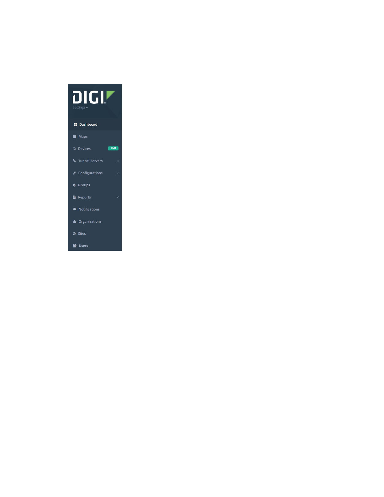
The navigation panel, which is found on the left side of every page, provides access to the main menu
with links to sections of the aView application. Several of the items have sub-menus that allow the
user to further narrow the selection.
Account Settings menu
The first menu item in the navigation panel is the user account's Settings menu.
Account
The Settings menu at the top of the Navigation panel includes the Account item, where a user can
access manage their user profile, change their password, and log out from the system. See Manage
User Preferences for information about your user profile.
Logging out of the aView application
The Settings drop-down at the top of the Navigation panel includes a Logout button. Clicking on this
will log you out of aView.
Search bar
In the toolbar at the top of each page of the aView site is a Search box that can be used to locate
specific devices or sites. Type the desired value, press Enter, and the selected entries will be
displayed. The search tool will match on the following fields:
n MAC address
n Serial Number
Digi aView User Guide
13
Page 14

Site navigation Organization Filter
n Modem ICCID
n Site ID
The Advanced Search link can be used to search for a device or site by more specific details; including
location, IP address, phone number, site ID, and cellular modem details.
Organization Filter
aView makes extensive use of the structure called the organization. An organization is a term used to
associate devices, sites, users, and configurations together. A sub-organization is a term that
describes an organization that is accessible under a higher level organization.
By default, the aView application displays information related to all organizations that you have
access to. To limit the organizations that are displayed:
1. On the tool bar, click the Filter button ().
2. Click Search for organization....
3. Type at least the first three letters of the organization. A list of organizations that match the
string is displayed.
4. Select the organization from the list.
5. Click Apply.
All displays throughout the aView application will now be limited to the selected organization and any
of its sub-organizations. To return to viewing information for all devices, click the Filter button again
and click Clear.
Filter bar
Many pages in the aView application have a filter bar at the top of the page that allows you to narrow
the list of items displayed on the page.
The type of filters changes depending on the type of detail being displayed. The items that can be
filtered are listed when you click on the filter bar. Multiple filters can be applied at once. Once a filter is
selected, the results on the page will automatically be filtered and refreshed.
You can remove the applied filters by clicking the x on the filter bar. The applied filters only apply to
the current page; if the user goes to a different page and comes back, the filters will be reset.
Some filters require the user to type in a value to be filtered on, such as the MAC address filter for
devices.
n Device-related filters:
l Categories: The category of devices (such as gateway, cellular, or WiFi).
l Deployment: What state the device is in (deployed or undeployed).
l Firmware: The firmware version of the device.
l Hostname: The network hostname of the device.
l MAC: The MAC address of the device.
l Model: The device model type (such as 8200 or 6200-FX)
l Organization: Filters based on the organization name.
l Site: The site name associated with the device.
Digi aView User Guide
14
Page 15

Site navigation Pagination
l Status: What status the device is in (such as up or down). Note, the status only applies to
deployed devices.
n Event related filters:
l Level: The severity level of the event. Each event is tagged with a certain severity level to
indicate the importance of the event (such as notice or alert). Severity levels are listed in
the filter from lowest severity to highest severity.
l Range: The time range of events to display. The default is to display the events for the past
30 days.
l Type: All events are tagged with a certain type, making it easy to associate similar events
together (such as DHCP, tunnel, or reboot).
n User-related filters (available only to users with sufficient privileges to view the Users page):
l Email: The email address of the user.
l Name: The name of the user.
l Organization: Filters based on the organization name.
l Status: The status of the user's account in aView. Active indicates that the user has logged
in within the past 30 days. If a user has not logged in within the past 30 days, they account
is set to inactive. A Pending account indicates the user has never logged in to aView.
l Timezone: The timezone selected by the user for displaying timestamps in aView.
Pagination
Several pages throughout the aView application have pagination, where only a certain number of
entries are listed on each page. The number of entries can be controlled by the Show n entries
pagination drop-down, which is always listed at the top-right of the table on the page.
Digi aView User Guide
15
Page 16
Site navigation Dashboard
Dashboard
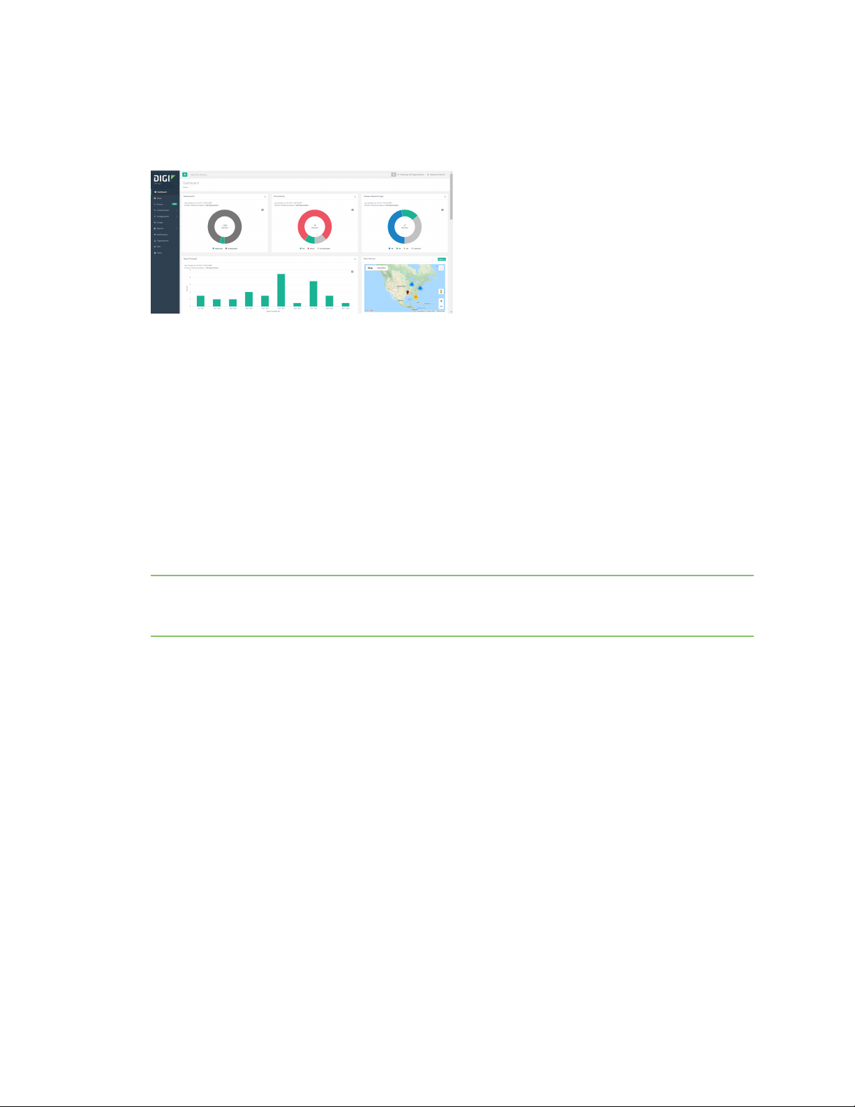
The Dashboard page displays several charts and other widgets to provide at-a-glance details for your
devices.
Within each chart, clicking on a displayed category will open a table of devices included in that
category. The following charts are provided:
n Deployment chart
n Connectivity chart
n Cellular Network Type chart
n Signal Strength chart
The Dashboard page also provides an Alert Devices map widget that displays devices in an alert
status. You can zoom in and out within the map, and select different regions to display. Click on a
status indicator to open a window containing detailed information on the device. From within the
window, you can click on the Organization name, the device's MAC address, or the Site ID to open
associated pages. Devices in an alert state are also listed in tabular form at the bottom of the
Dashboard page.
Note The dashboard page does not automatically refresh, so the devices listed in on the dashboard
page were in alert status at the time of when the page loaded. If the page is left alone for an
extended period of time, the listed devices in alert state may become outdated.
Deployment chart
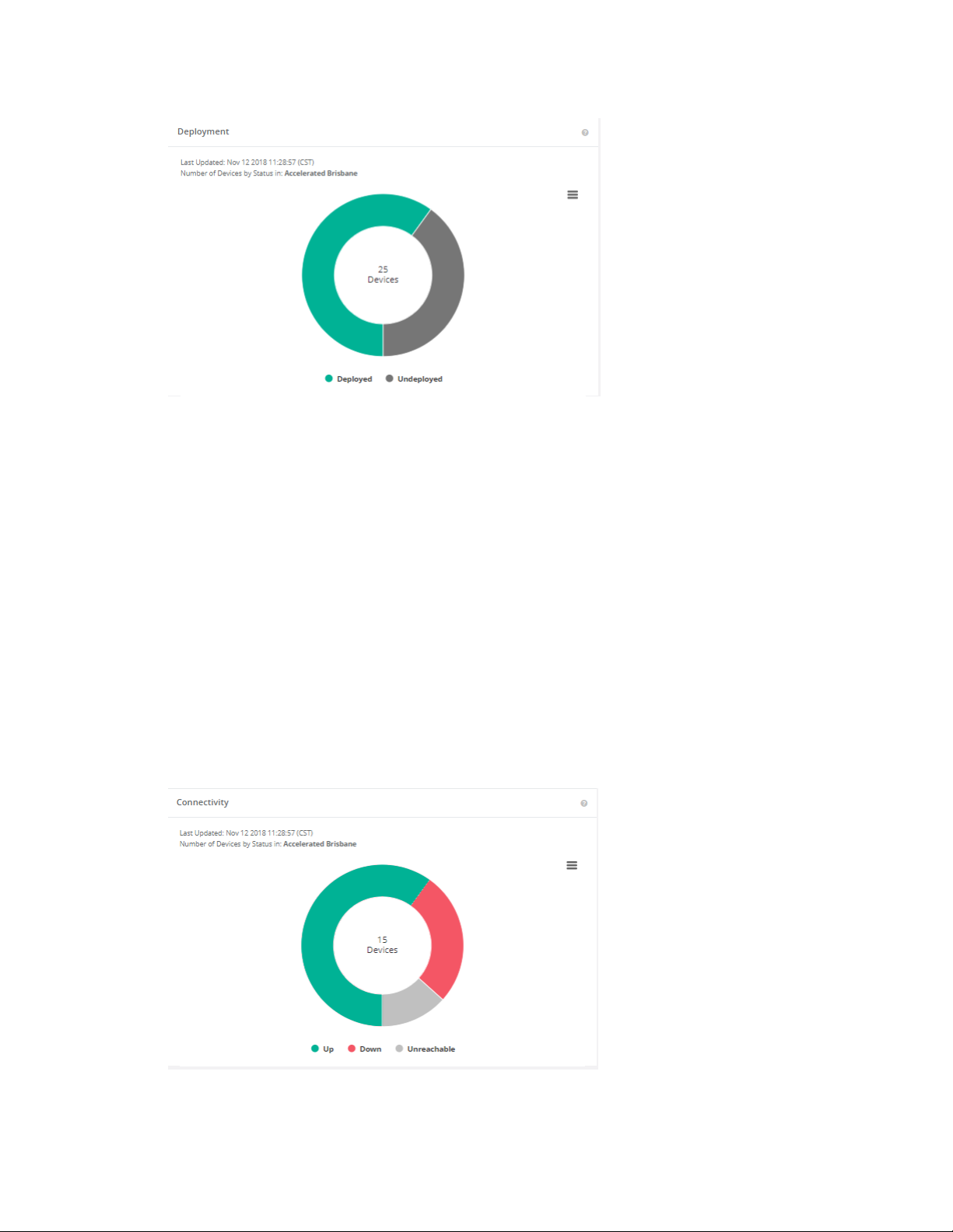
The Dashboard Deployment widget displays a donut-style chart that provides a breakdown of
deployed and undeployed devices in the organization. A device's deployment status indicates whether
or not aView should provide active monitoring and alerts for the router.
Digi aView User Guide
16
Page 17
Site navigation Dashboard
Click on an area in the chart to open the Devices page listing all of the organization's devices with this
deployment status.
n Deployed: Indicates the number of devices that have been deployed, which means that they
will be monitored based on the events that are sent by the device, and will also generate
notification alerts based on the events received and your access to the device. In the Devices
page, devices that have been deployed will be listed with a particular deployment status (for
example, Up, Down, or Inactive). Further dashboard information is provided for deployed
devices in the Connectivity chart and Cellular Network Type chart.
n Undeployed: Indicates the number of devices that have not been deployed, which means that
they should not be monitored. aView will list details and events for undeployed devices, but
these events will not generate any notification alerts. Undeployed devices will be listed in the
Devices page with a pause icon () as their status.
Connectivity chart
The Dashboard Connectivity widget displays a donut-style chart that provides a breakdown of the
connectivity status of deployed devices in the organization. The chart only reports on the main
statuses of Up, Down, and Unreachable.
Digi aView User Guide
17
Page 18
Site navigation Dashboard
Click on an area in the chart to open the Devices page listing all of the organization's deployed devices
with this connectivity status.
n Up: The device is online and is reachable through aView.
n Down: The device is not reachable through aView.
n Unreachable: The device has never checked into aView even though it is in a Deployed state.
Note The Grace Period Duration and Heartbeat Interval device configuration options control the
amount of time that aView should wait before reporting a device as Down. For example, the default
Grace Period Duration for cellular devices is 109 minutes, and the default Heartbeat Interval is 30
minutes. When combined, this means that by default, aView will consider a cellular device to be down
if it has not heard from the device in 139 minutes. See Configure down status options for devices for
more information about the Grace Period Duration and Heartbeat Interval options.
Cellular Network Type chart
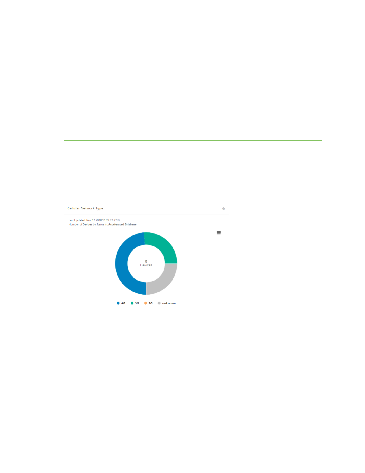
The Dashboard Cellular Network Type widget displays a donut-style chart that provides a
breakdown of the cellular connectivity type for deployed cellular-enabled devices. The type of cellular
connection can vary depending on availability of service, quality of connection, and device
configuration. You should verify the anticipated connection type and the APN associated with the
cellular data plan before troubleshooting a device's type of cellular connectivity.
Click on an area in the chart to open the Devices page listing all of the organization's devices with this
cellular connectivity type .
LTE status indicators on your device displays the device's cellular network type using the same color
codes used in Cellular Network Type chart. A blue light (solid or blinking) indicates a 4G connection, a
green light (solid or blinking) shows the router is on 3G, and so forth.
Signal Strength chart
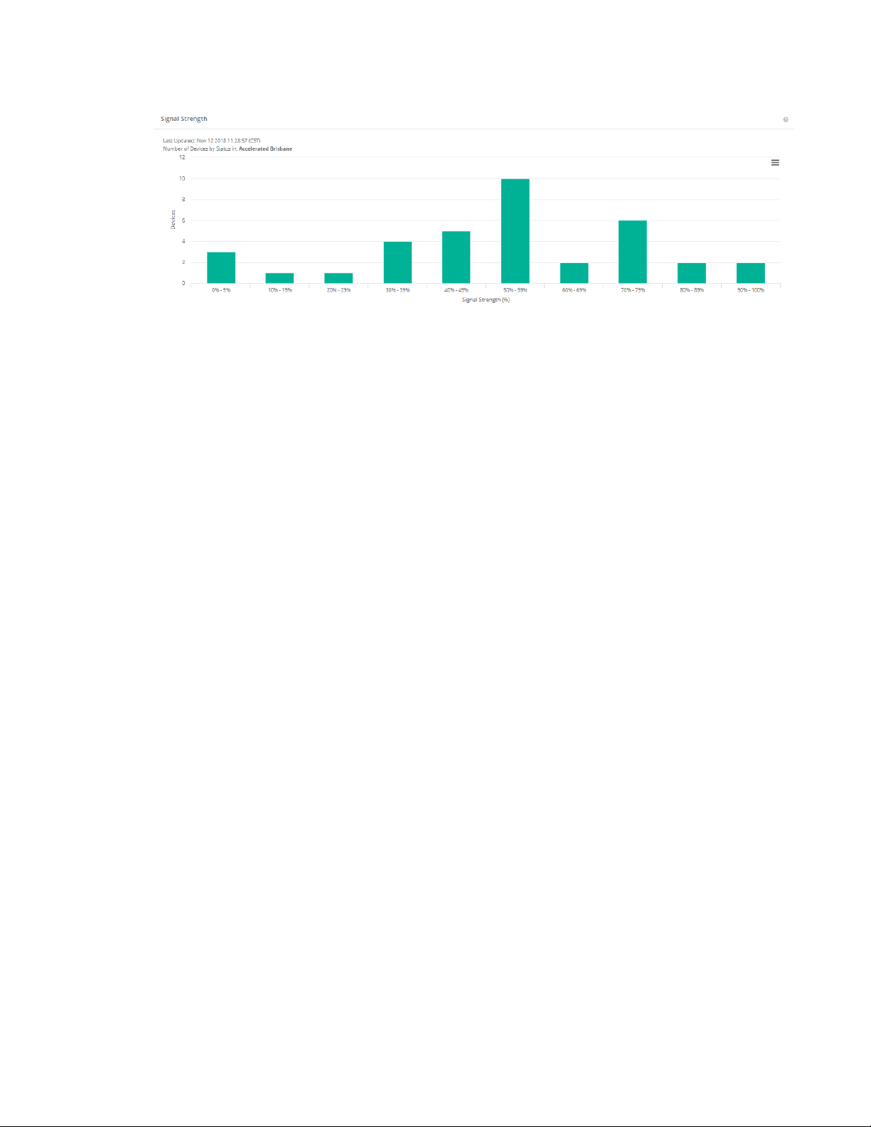
The Dashboard Signal Strength widget displays a bar graph representing the reported signal
strength percentage of deployed devices in the organization.
Digi aView User Guide
18
Page 19
Site navigation Dashboard
Click on one of the bars in the graph to open the Devices page listing all of the organization's devices
with this reported signal strength.
Export a chart
Dashboard widget charts can be exported to the following formats:
n PNG image
n JPEG image
n PDF document
n SVG vector image
To export a dashboard widget chart:
1. When a chart is displayed, click (Chart menu).
2. Select the appropriate Download type from the menu.
Print a chart
To print a chart:
1. When a chart is displayed, click (Chart menu).
2. Select Print chart.
3. Fill in print options and click Print.
Digi aView User Guide
19
Page 20
Site navigation Maps
Maps
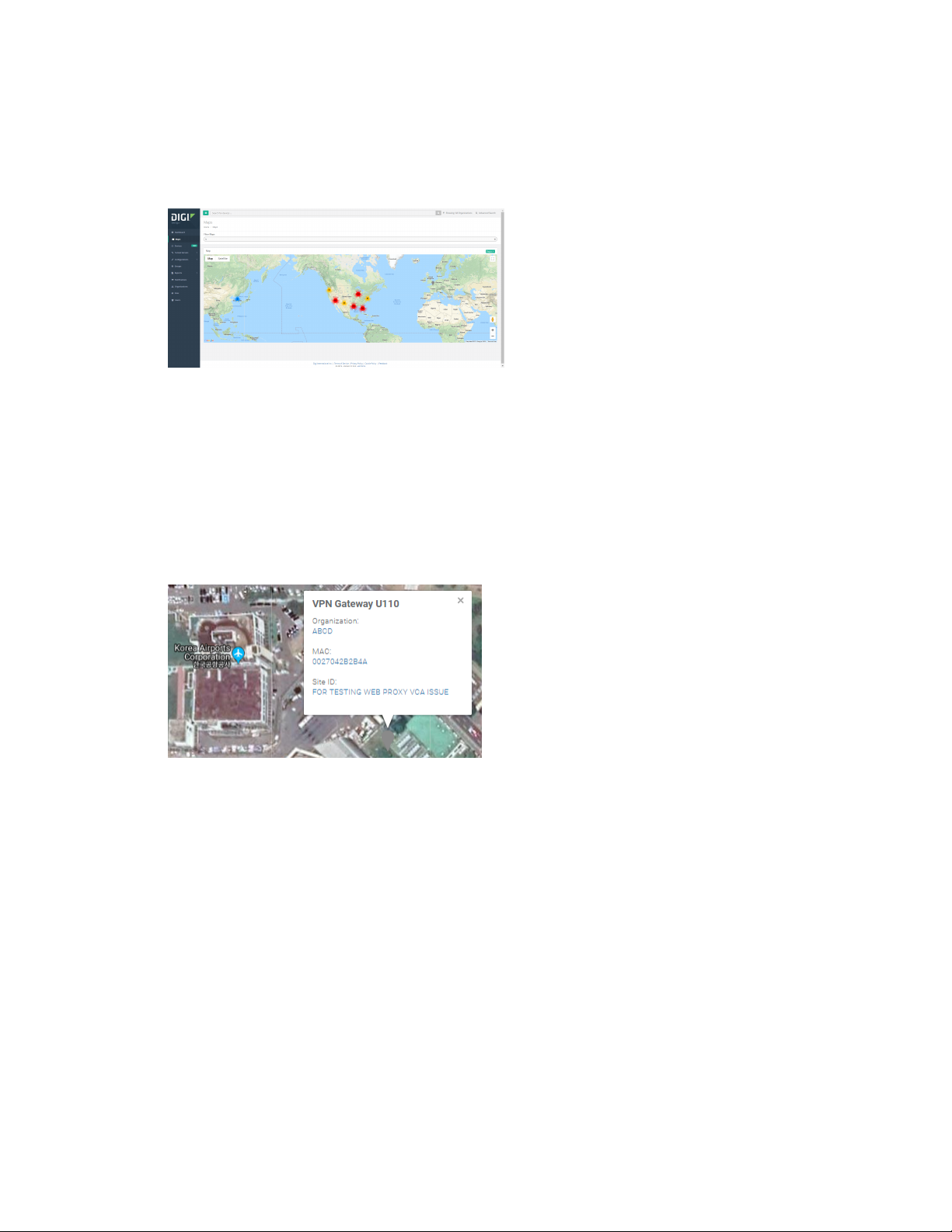
The Maps page displays the graphical view of monitored devices on a world map. The maps allows a
user to drill down on specific units and their current status. When global devices are being managed, a
specific country or region can be selected.
The Maps page displays the status of the various devices visually on a map of the organization’s home
country. The map can be zoomed in and out to display finer levels of granularity all the way to a single
site. The map can be filtered by organization, device category, device type, status, and country/region.
Changes can be made to any filter criteria before filtering the map. A user can also toggle the map
between a street view and geographical view.
Once the desired devices are displayed a user can obtain more detailed information on a particular
site by clicking on the status indicator display. This will display an information bubble with the device
type, site ID, and device information. Clicking on the Organization will direct the user to a page that
lists all the devices associated with that organization. Clicking on the site ID will direct the user to a
page that lists all the devices associated with that site ID in that particular organization.
Digi aView User Guide
20
Page 21
Site navigation Devices
Devices
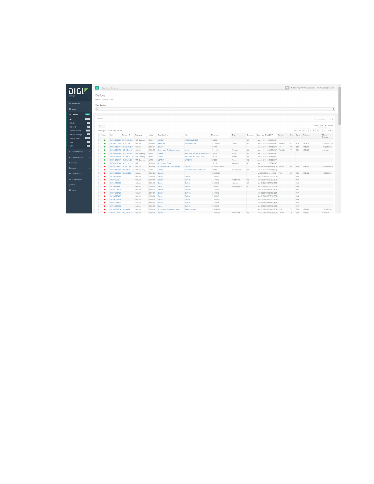
The Devices page displays the status of all devices that you have access to. Clicking on the Devices
page menu option in the navigation bar displays a drop-down to specify the type of device. You can
also select All to display all devices without regard to the device type.
The Devices page allows you to display the current status of all devices managed by their
organization. The filter bar also allows you to select only a certain category of devices (for example,
VPN, WiFi, Cellular).
Once you have selected a category of devices, aView displays a tabular tab of the devices and their
current statuses. The filter bar can be used to filter the results, so that only the relevant devices are
shown. You can select the organization that should be displayed and then further narrow the results
down by filtering on the device type or status.
Devices are listed in the table can include the following details. Display additional details, or hide
details, by selecting the wrench icon () at the top-right of the table.
n Status: The status displayed is a color coded indicator. See Color indicators for details on each
status color.
n MAC: The MAC address of the device generating the event. The MAC address field is selectable.
Clicking this link will direct the user to the device's details page. For additional information
about the device's details page, refer to the section of this guide that details the specific device
category that is being viewed.
n Comment: Provides a bubble icon. Mouse-over the bubble icon to view a comment associated
with the device, or click the bubble icon to open a dialog that you can use to enter or edit a
comment.
n Primary IP: The device's primary IP address.
n Management IP: IP address used by aView to manage the device.
n Hostname: The WAN IP address of the device. Clicking the link provided in the field will open a
new URL with the host as the URL. For example if the host is 172.16.3.2, the URL will be
https://172.16.3.2
Digi aView User Guide
21
Page 22
Site navigation Devices
n Category: The category of the device.
n Model: The model of the device.
n Organization: The organization that the device is associated with. A device is assigned to an
organization when it is entered into aView. In most cases the organization will be the company
or one of its sub-organizations. This field is selectable. Clicking the link in this field will display
all the devices associated with that organization and any sub-organizations under it.
n Site: The site ID that the device is associated with. Clicking the link in this field will display all
the devices associated with that site ID in the same organization.
n Firmware: The firmware version the device is currently running on.
n City: The city where the device is located.
n Country: The country where the device is located.
n Activation Date: The timestamp of when the device first reported in to the aView site.
n Last Heartbeat: The last time the device has checked in with aView.
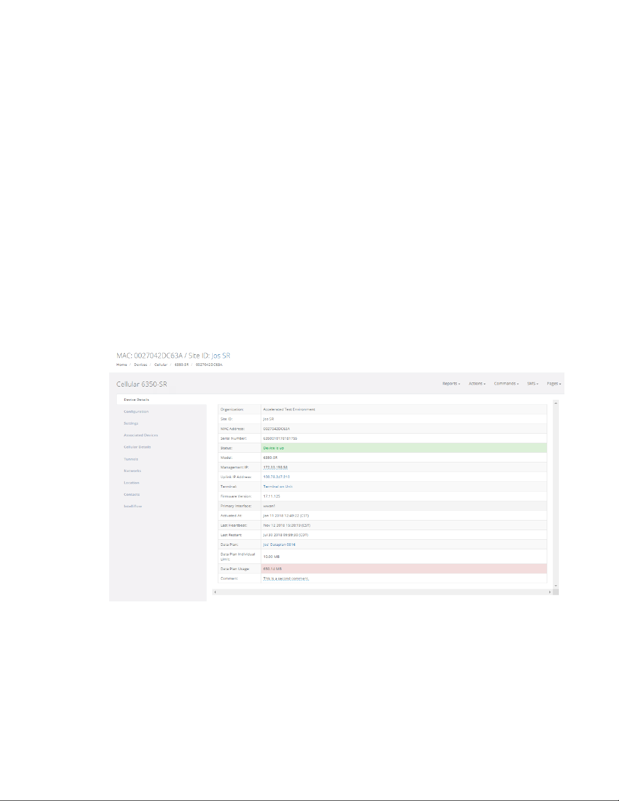
Device details page
Clicking on the Device ID (MAC address) of a device will display the device's Device Details page. This
includes detailed information about the specific device. The following sections describe the details
that are found on the Device Details page that apply to all categories of devices.
Settings tab
The Settings tab contains attributes that can only be updated if you have the appropriate
permissions. If you do not have permissions to edit these settings, this tab will not be listed. If you do
have the ability to edit these settings for the device, then the options will be listed in an edit mode,
with drop-downs and input text boxes listed. Multiple options can be edited at the same time. Once
any desired updates have been made, click Update Settings.
Digi aView User Guide
22
Page 23

Site navigation Devices
Options available in the Settings tab vary depending on the device. Common options for all devices
include:
n Organization: The organization that the device is currently associated with. If the user has the
ability to change the device's organization, a button labeled Change will be displayed that,
when clicked, will allow a user to move the device to a new organization. When moving the
device to a new organization, the user can also optionally copy the device's site and/or data
plan (if any).
n Site ID: The site ID that the device is associated with. Clicking the link in this field will display all
the devices associated with that site ID in the same organization.
Details tab
The Details tab contains specific information that identifies the device. The following is a list of details
that apply to all devices:
n Status: The current status of the device when this page was loaded.
n MAC Address: The MAC address of the device.
n Device Details: The serial number of the device.
n Model: The model of the device.
n Firmware Version: The firmware version the device is currently running on.
n Activated At: The timestamp of when the device first reported in to the aView site.
n Last Heartbeat: The last time the device has checked in with aView.
n Last Restart: The last time the device rebooted.
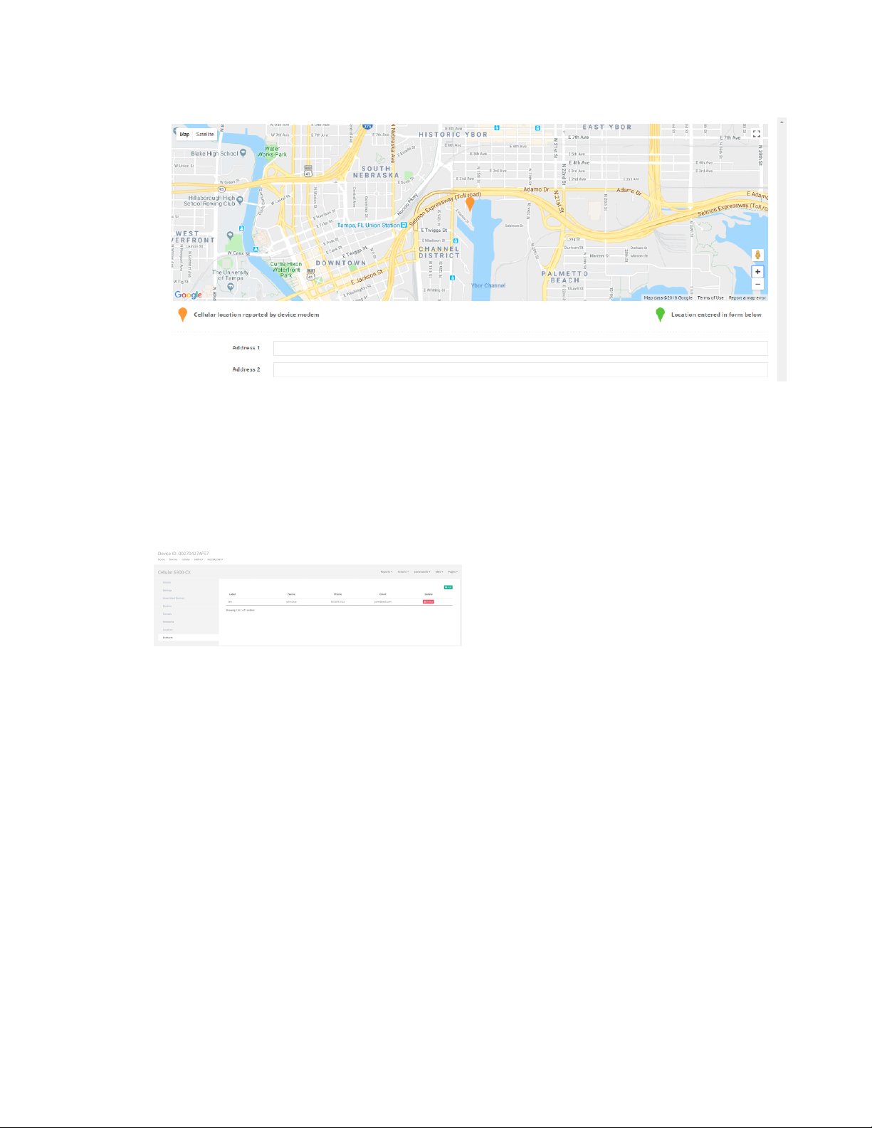
Location tab
The Location tab displays the location of the device on a geographical map based on the device's
address details. Depending on your permissions, the location details may be listed in a view-only
mode, or there will be editable text boxes and drop-downs to update the location if desired.
To add or update a device's location, enter in a valid address into the location details. Once all desired
address details have been typed in, click Update. The aView application will send the address details
to GoogleMaps to validate the address, and the map will be updated.
If Google does not return a valid address, aView will save the address details as entered. However, the
aView application will not display a map of the address details since Google did not return valid
latitude/longitude coordinates.
Clicking Clear will remove the location details for the device and remove the map from the page.
Cellular location
If aView has valid GSM location details for a device with cellular capabilities, a second pin, colored
orange, will appear on the map to indicate the location determined using these GSM details.
Digi aView User Guide
23
Page 24
Site navigation Devices
Contacts tab
The Contacts tab displays any contacts that are associated with the device. A contact must contain a
name and email address, along with an optional phone number. When creating a new contact, the
contact can be designated as a general, technical, sales, or site contact. The same contact info can be
used for multiple devices. Once a contact is made, the user can apply the same contact to another
device by going to the new device's details page, click the green Add button, and then select the
appropriate contact from the drop-down list of existing contacts.
Reports menu
The Reports menu provides a drop-down list of available reports that can be performed for the device.
Available reports vary depending on the device type. See Generating reports for details on report
types.
Actions menu
The Actions menu provides a drop-down list of available actions that can be performed concerning the
device in aView.
n Subscribe/Unsubscribe: Allows a user to subscribe to or unsubscribe from receiving
notification alerts from the device. See Manage User Preferences for details about managing
notifications and profiles.
n Deploy/Undeploy: Controls the deployment of a device. See Monitoring devices for details
about the deployment status and deploying devices.
Commands menu
The Commands menu provides a drop-down list of available remote commands that can be sent to
the device. Clicking on a command will execute that command. For a list of available device commands
Digi aView User Guide
24
Page 25

Site navigation Devices
and details of what they do, refer to the Remote Commands section of the particular device category
in this guide.
Pages menu
The Pages button provides a drop-down list of pages related to the individual device.
n Details: Displays the Device Details page. If you are already on the device details page, the
page will simply refresh.
n Events: Displays the Events page for the specific device. See Device events for details about
the Events page.
n Raw Events: Displays a list of events in raw format.
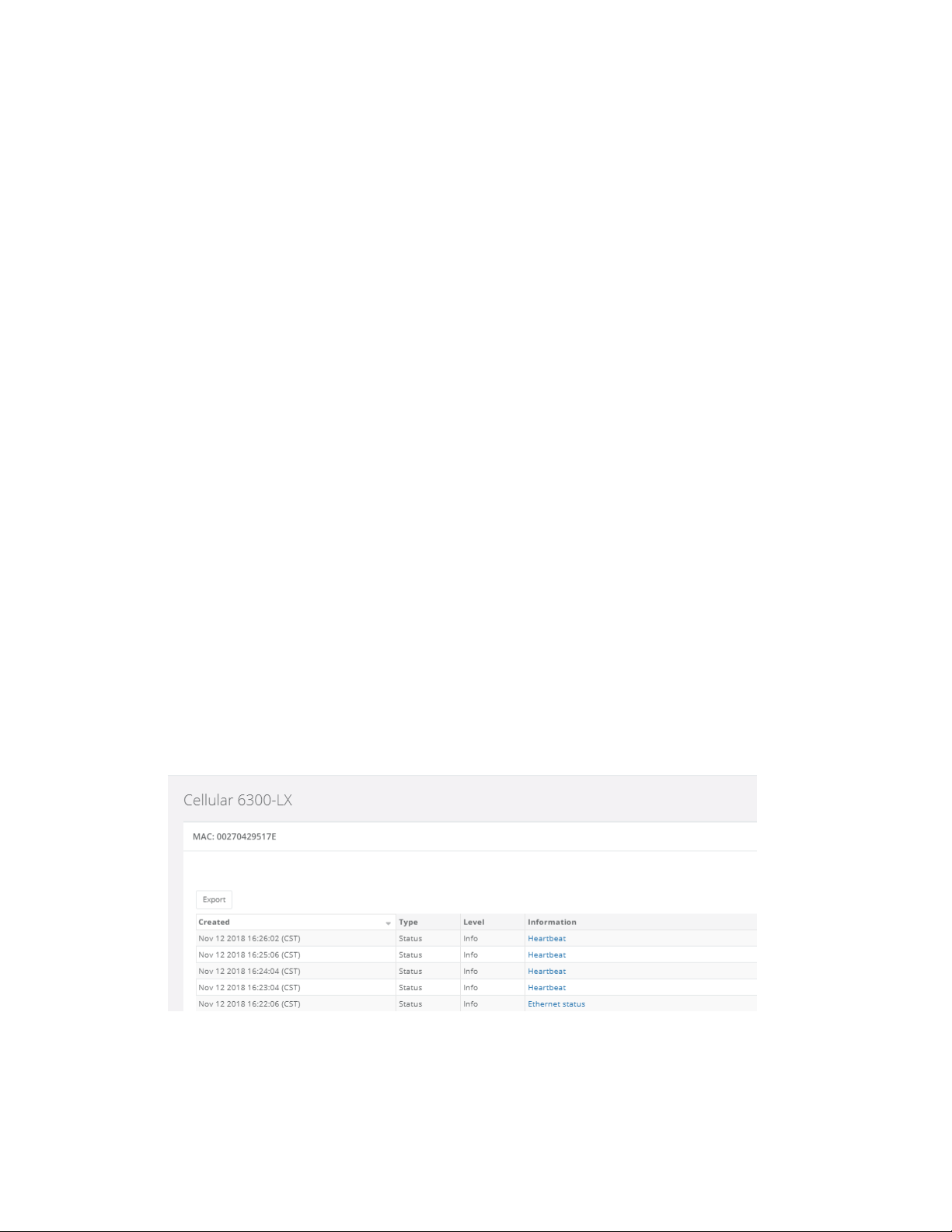
Device events
The Device Events page is displayed by selecting Pages > Events on a device's Device Details page.
This pages displays a real-time chronologically sorted table (newest on top) of device events for the
individual device. Event management provides a set of alert conditions that are significant to the user.
As the event conditions are detected, they are categorized and color-coded for easy recognition.
Critical errors and alerts are colored red, while warnings and notices are orange or yellow. All other
device events are informational only and not color-coded.
The Events page refreshes automatically every few seconds, to keep the information on the page up
to date.
Note aView stores the past 30 days of event history for each device.
Using the Filter Menu at the top of list, you can filter the events in the following ways:
n Level: Severity level of the alert. selected at once.
n Range: The time range of events to display. The default is to display the events for the past 24
hours.
n Type: The type of events displayed can be filtered.
You can also export the current page or all events by clicking the Export button.
Event details
All events are listed with the following information:
n Created: The date that an event occurred and time that the event occurred. The time is
displayed in the time zone of the user.
Digi aView User Guide
25
Page 26
Site navigation Devices
n Type: The state of the device that is generating the event. There are currently seven different
states that a device can be in.
l Status: Device is reporting its current operational status.
l Configuration: Device or remote operation has initiated a configuration change or
information request.
l Firmware: A firmware action has been initiated or the device determined there was a
conflict.
l Reboot: The device has restarted.
l DHCP: The device is reporting a change in its DHCP configuration.
l Tunnel: VPN tunnel status.
l Remote: A command has been received from the portal and an action initiated.
n Level: The severity level of the event being displayed. aView supports a modified version of the
severity levels defined by RFC 5424. The supported six levels of events are listed from lowest to
highest alert level below.
l Debug: Info useful to developers for debugging the application, not useful during
operations.
l Info: Normal operational messages – used for reporting, measuring throughput, etc. - no
action required.
l Notice: Events that are unusual but not error conditions. No immediate action required.
l Warning: Warning messages. Not an error, but indication that an error will occur if action is
not taken. This message indicates an item that must be resolved within a given time.
l Error: Non-urgent failures, these should be relayed to developers or admins; each item
must be resolved within a given time.
l Alert: Should be corrected immediately, therefore the appropriate action or support
notification should be initiated to fix the problem.
n Information: The data that the device transmitted to aView. These messages can be simple
text messages or complete hardware status displays. The information field is selectable.
Clicking this link will direct the user to a page that displays all the information of the individual
event, including a detailed description of what has occurred.
Digi aView User Guide
26
Page 27

Site navigation Tunnel servers
Tunnel servers
The Tunnel Servers page displays all the known VIG and SIG tunnel endpoints that VPN Gateway
devices in aView are connected to. Each tunnel server is listed in the table with the following details:
n Name: The name of the tunnel server. Clicking on the name will direct the user to a page that
lists details for each VPN Gateway device connected to that tunnel server.
n Devices: The number of devices connected to the tunnel server.
n IP Addresses: The number of IP addresses associated with the tunnel server. Depending on
the network setup, a single tunnel server could have multiple IP addresses and physical
servers pooled together that makes up the tunnel server network.
n Type: The type of tunnel server; typically either a VIG or SIG.
n Location: The listed location for the tunnel serer.
Digi aView User Guide
27
Page 28
Site navigation Configurations
Configurations
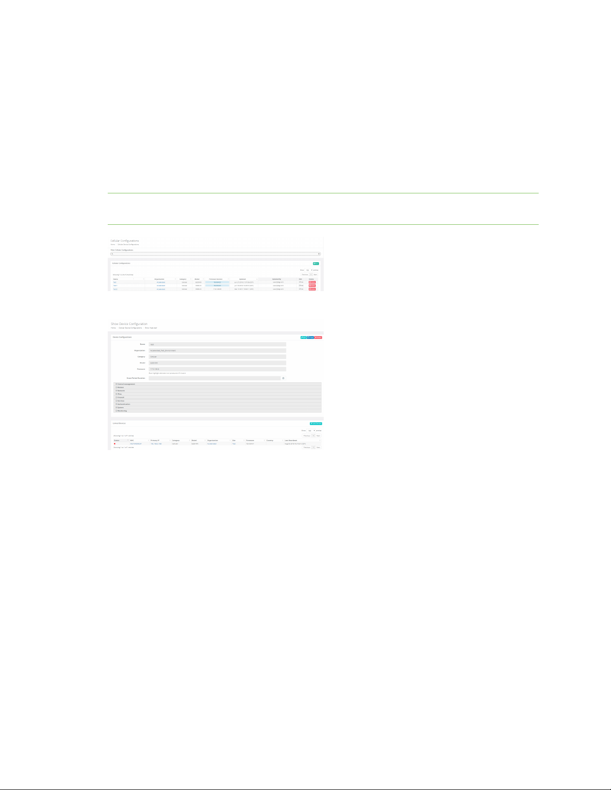
The Configurations page displays the device configuration profiles available to the user.
To open the Configurations page:
1. Click Configurations in the navigation bar.
A sub-menu is displayed, listing categories of device configurations.
2. Click the appropriate type of device configuration from the sub-menu. For details of each
configuration option, refer to the individual device configuration sections of this guide.
Note Users must have appropriate permissions to make changes to configurations. See Permissions
for details about how to configure user permissions.
Click on the name of a configuration to open the Show Device Configuration page.
Any values in the configuration that are inherited from the parent configuration are highlighted in red.
Edit the configuration profile by clicking Edit in the top right of the configuration. You can also copy the
configuration by clicking Copy.
All devices that the configuration profile is linked to are listed at the bottom of the profile. These are
referred to as "linked devices".
Digi aView User Guide
28
Page 29
Site navigation Reports
Reports
aView allows you to create a variety of reports based on various selection criteria. The Reports
feature can be selected by clicking on Reports in the navigation panel, and then selecting the desired
report type.
See Generating reports for details on report types.
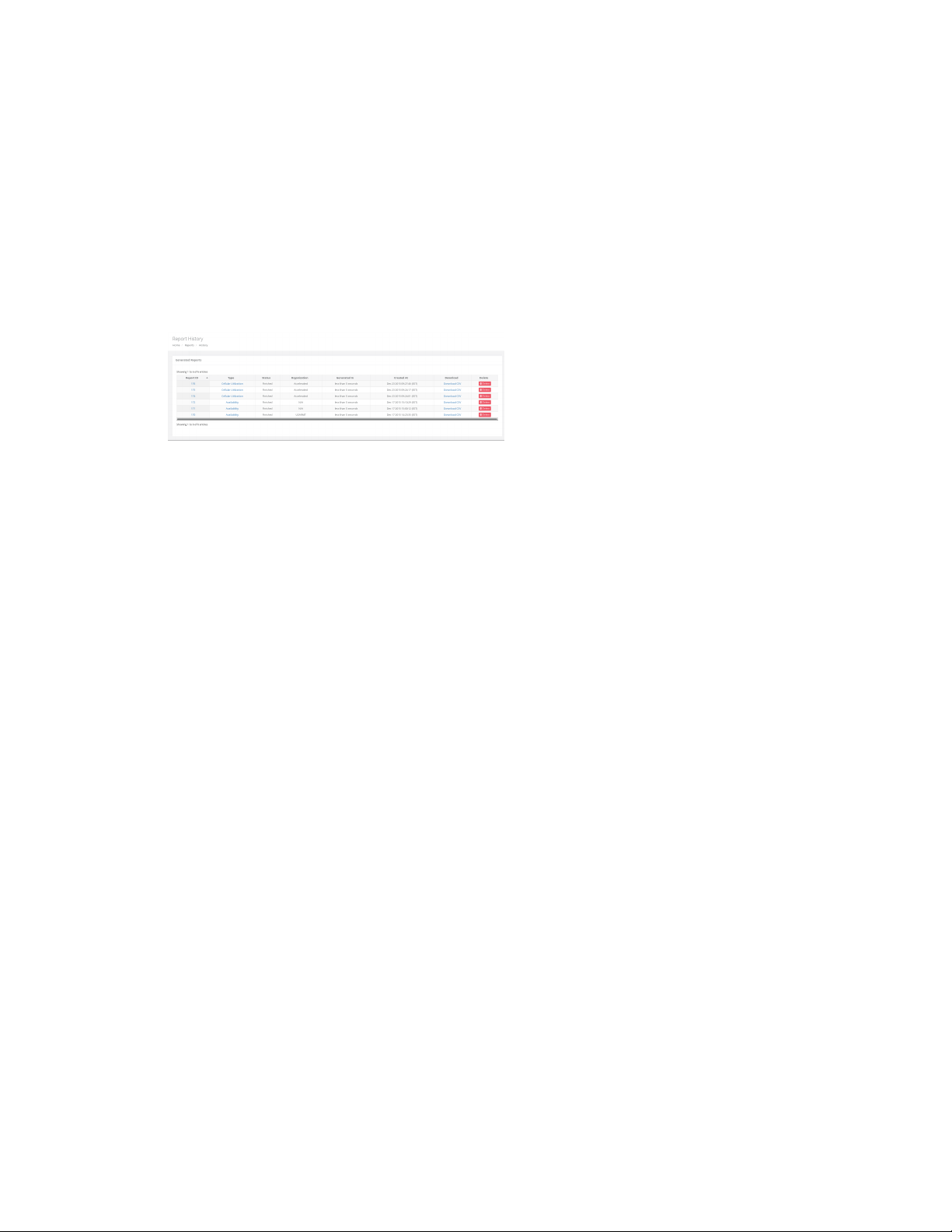
Report history
aView will retain up to ten generated reports per user. These reports can be viewed by clicking on the
History link in the Reports drop-down menu of the navigation bar.
Click on a report ID to display a page with the results of the report. Export a report to a CSV file by
clicking Download CSV.
Digi aView User Guide
29
Page 30
Site navigation Notifications
Notifications
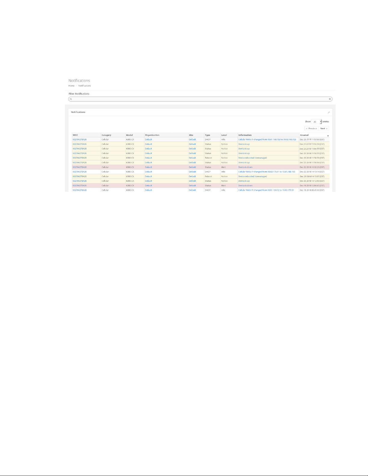
The Notifications page displays the notifications that were sent to the user based on their
notification subscriptions. See Managing Notifications for details on notification subscriptions.
The Notification page is a convenient way to look at a list of alerts that have been sent to you. The
Information column provides a summary of the content of the notification for quick reference.
Clicking on an entry in the Information column will open a window listing the raw data of the event;
click Go To Event to view the event that spawned the notification.
You can filter notifications for categories like device type and severity. See Device events for further
information about the event-related filters available for notifications.
Digi aView User Guide
30
Page 31
Site navigation Organizations
Organizations
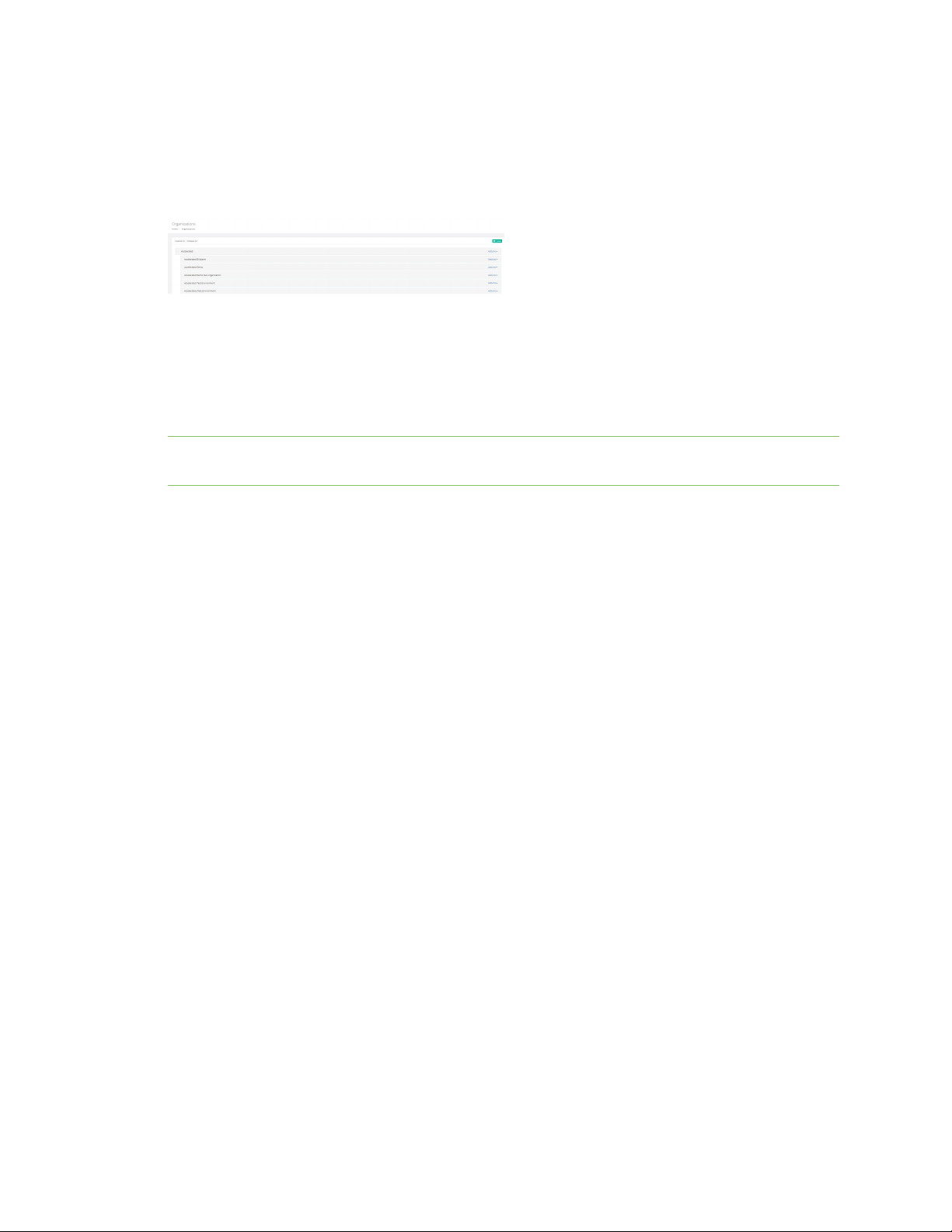
The Organizations page displays all organizations that you have access to.
An organization is a logical entity used to associate devices together. It does not necessarily
represent a client.
Clicking on an organization name will display a page listing all devices associated with the
organization and all sub-organizations.
Each line also has an Actions drop-down that allows you to display the organization's devices and to
subscribe to notifications from the organization's devices. Additionally, if your user role includes the
Modify Organizations permission, you can edit the organization settings, add new users, add new
sub-organizations, and delete the organization.
Note Deleting an organization will also delete any devices, users, and sub-organizations associated
with that organization.
Create a new sub-organization
Creating new subscriptions requires that your user role includes the Modify Organizations
permission. See Roles for more information about user roles.
To create a new sub-organization:
1. From the navigation panel, click Organizations.
The Organizations page displays.
Digi aView User Guide
31
Page 32
Site navigation Organizations
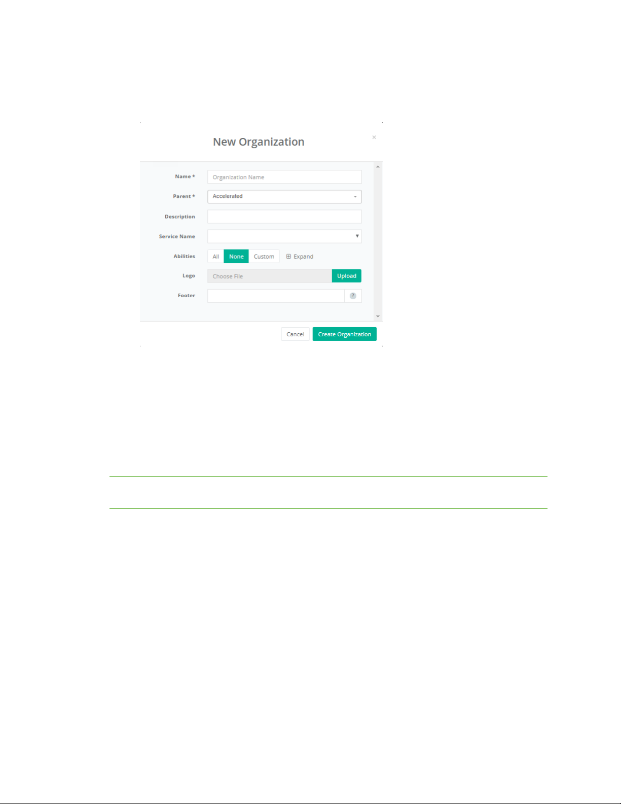
2. Click Actions on the right hand side of an organization’s row, and select New Sub
Organization.
The New Organization dialog appears.
3. Enter a name for the organization and an optional description.
The remaining fields in the New Organization dialog are described in the following sections.
4. Click Create Organization when complete.
Organization abilities
Part of the purpose of an organization is to control the access users within that organization have to
aView. When creating an organization, there are a list of roles that must be selected to specify the
access that organization will have to its devices.
Note Configuring an organization's abilities can only be performed when creating a new organization
and cannot be edited after the organization has been created.
1. Follow instructions at Create a new sub-organization to create a new organization.
2. For Abilities, select All, None, or Custom.
Digi aView User Guide
32
Page 33

Site navigation Organizations
3. If Custom is selected for Abilities, click Expand to expand a list of available abilities. The
following abilities are available:
n Modify Sites: Controls the ability for users within the organization to edit the Site IDs
associated with that organization.
n Modify Devices: Controls the ability for users within the organization to edit the
options listed in the Admin Panel section on a device's details page, as well as
deploying/undeploying devices.
n Modify Organizations: Controls the ability for users within the organization to edit any
sub-organizations that the organization has.
n Modify Users: Controls the ability for users within the organization to edit the settings
and permissions of other users.
n Modify Configurations: Controls the ability for users within the organization to edit the
Legacy Cellular configuration profiles of a device.
n Replace Devices: Controls the ability for users within that organization to move devices
from one organization to another.
n Import Devices: Controls the ability for users to add new devices into aView with the
import tool.
n Modify Device Configurations: Controls the ability for users within the organization to
edit the Cellular, Dial-to-IP and Remote Manager configuration profiles of a device.
n View Configuration History: Controls the ability for users within the organization to
view the history of changes made to a device's configuration profile.
n View Admin Panel: Controls access to the Admin panel of the site. If enabled, the
Admin panel will be accessible by a link in the right section of the top navigation bar
(between the Account and Logout buttons).
n Deploy Devices: Controls the ability for users within the organization to deploy or
undeploy devices. For more information on what device deployment, please refer to the
Monitoring Devices section of this guide.
n Send Device Commands: Controls the ability for users within the organization to send
remote commands to devices.
n Assign Non-Production Firmwares: Controls the ability for users within the
organization to select non-production firmware versions in a device's configuration
profile.
4. Click each ability that should be applied to the organization.
5. Complete the other information in the dialog as necessary and click Create Organization.
Optional service name
You can associate a Service Name to an organization, as a way of indicating what level of service a
support company provides to the organization. Adding or modifying the service name requires that
your user role includes the Modify Organizations permission. See Roles for more information about
user roles.
To add or modify the Service Name for an organization:
1. From the navigation panel, click Organizations.
The Organizations page displays.
Digi aView User Guide
33
Page 34
Site navigation Organizations
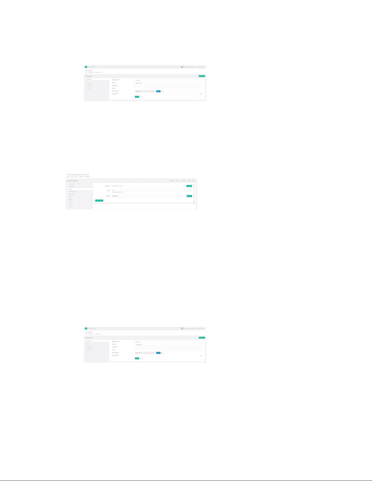
2. Click Actions on the right hand side of an organization’s row, and select Edit Settings.
The organization's page appears.
3. Click the down arrow () for the Service Name field and select the appropriate Service Name.
If the desired Service Name is not available, please contact your aView admin to have the
Service Name included.
4. Click Update.
Once the Service Name has been assigned to an organization, it will be displayed on any device in that
organization or any of its sub-organizations. Also, any notifications that get sent from aView for the
organization's devices will include the Service Name in the notification details.
Optional logo and footer
The logo that will appear in the aView application, and the footer text displayed at the bottom of the
application, can be changed at an organization level. Any footer that is set for the organization will be
applied to all sub-organizations. Footer text can be either text or valid HTML. Adding or modifying the
logo and footer requires that your user role includes the Modify Organizations permission. See Roles
for more information about user roles.
To set or update the footer text for an organization:
1. From the navigation panel, click Organizations.
The Organizations page displays.
2. Click Actions on the right hand side of an organization’s row, and select Edit Settings.
The organization's page appears.
3. For Logo File (optional), click Upload and select the logo file.
4. For Footer (optional), type in the desired footer text in either text or valid HTML format.
5. Click Update.
Roles
The organization's Roles tab is used to group various abilities into roles that can then be assigned to
one or more users within that organization to define their permissions when using aView. See Users
Digi aView User Guide
34
Page 35
Site navigation Organizations
for information about creating and assigning roles to users.
See Organization abilities for information about the available abilities.
Note Your user role must include the Modify Organizations ability in order to view or edit an
organization's user roles.
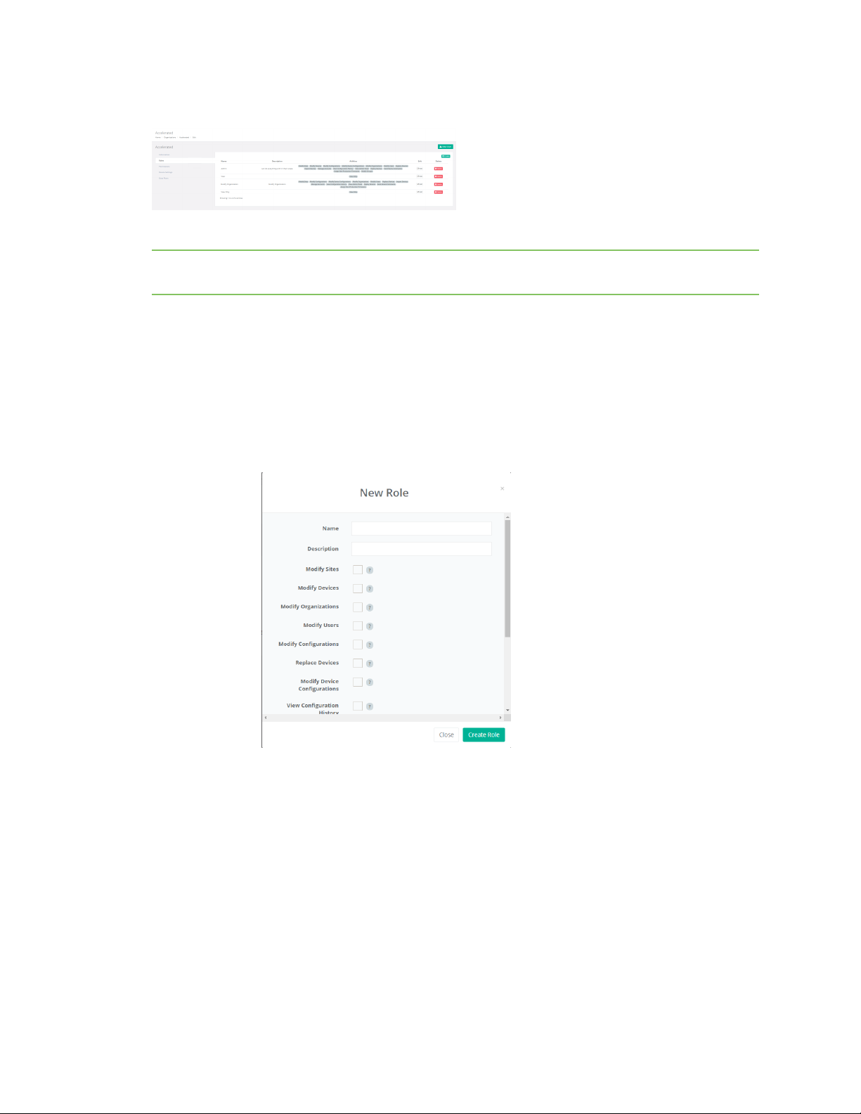
To view and edit an organization's roles:
1. From the navigation panel, click Organizations.
The Organizations page displays.
2. Click Actions on the right hand side of an organization’s row, and select Roles.
3. To create a new role:
a. Click Create.
The New Role dialog displays.
4. To edit an existing role:
Digi aView User Guide
b. For Name, type a name for the role.
c. Type an optional description for the role.
d. Click the check box for each applicable ability to be included in the role. You can also
click Check all or Uncheck all at the bottom of the list of abilities.
e. Click Create Role.
a. Click Edit on the right hand side of an role's row.
The Edit Role dialog displays.
b. Make any appropriate changes to the role.
c. Click Update Role when complete.
35
Page 36
Site navigation Organizations
Permissions
The organization's Permissions tab allows you to view and assign roles to an organization. See Roles
for more information about creating and editing roles that are available for the organization.
To view and assign roles for an organization:
1. From the navigation panel, click Organizations.
The Organizations page displays.
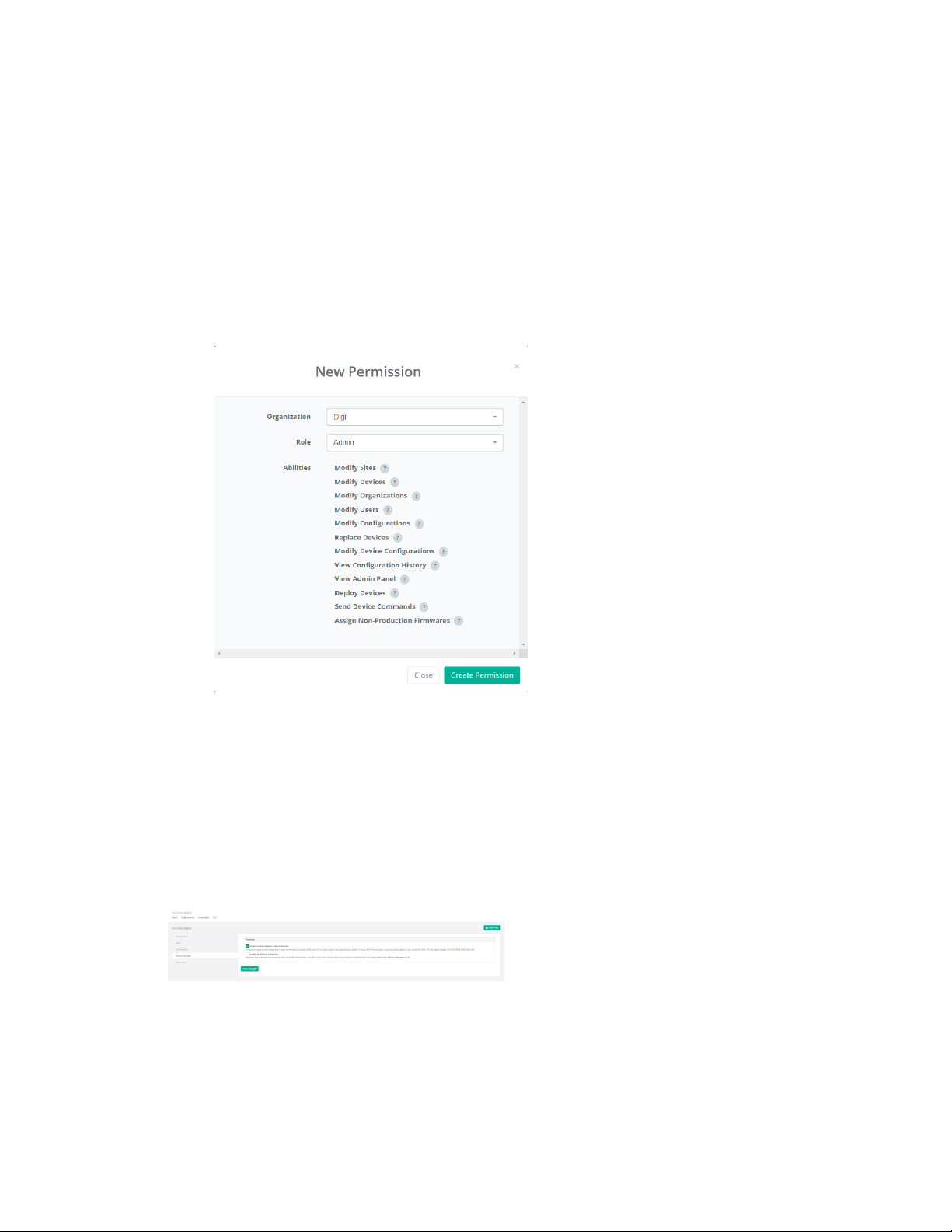
2. Click Actions on the right hand side of an organization’s row, and select Permissions.
3. To assign a new role to the organization, click Create.
The New Permission dialog appears.
4. For Role, select the appropriate role to include for the organization.
5. Click Create Permission.
You can also change the assigned role for a permission by clicking Edit on the right hand side of an
permission’s row and selecting a new role for the permission.
Device settings
The Device Settings tab contains all selections to enable or disable optional details or metrics for
devices in that organization or its sub-organizations.
The following options are available in the Device Settings tab.
n Gateway—Enable Cellular Modem Data Collection: when enabled, the aView application will
collect cellular statistics from all VPN Gateway devices that belong to that organization or any
of its sub-organization. These cellular utilization statistics will be displayed on the device's
Digi aView User Guide
36
Page 37
Site navigation Organizations
details page as the Cellular Utilization chart and the Modem tab. Refer to the Gateway Devices
section for more details. The cellular statistics can also be used to generate cellular-based
reports for VPN Gateway devices.
n Gateway—Enable VLAN Data Collection: when enabled, the aView application will collect
details of the LAN ports of the VPN Gateway device, including the VLAN IDs associated with the
LAN ports.
Data plans
The Data Plans tab allows authorized users to create and manage cellular data plans for the selected
organization. Once a data plan is created, the user can apply that data plan to one or more devices by
selecting the data plan under the Settings tab on the details page for the device.
n Name: The name of the data plan. Clicking on the data plan name will display a list of the
devices associated to that data plan, including how much data each device has used under the
data plan.
n Number of devices: The count of devices assigned to this data plan.
n Data Limit: The amount of data usage at which point a notification should be generated for the
data plan. Note that for this notification to be generated, the Overage Notification option must
be selected.
n Data Used: The amount of data used by the devices that belong to the data plan.
n Individual Data Limit: The amount of data usage for each device under the data plan at which
point a notification should be generated. To receive this notification, a user must subscribe to
the device and select the Device data usage over limit option in the notification profile. For
additional details on setting up a notification profile, refer to the Notification Profiles section.
n Start Day: The day of the month to reset the Data Used value of the data plan.
n Overage Notification: Selecting this option will send a notification when the Data Used value
of the data plan exceeds the Data Limit option of the data plan. When triggered, this
notification will be sent to all users that belong to the same organization that the data plan
belongs to.
n Created: The time when the data plan was created.
SNMP probes
VPN Gateway devices are monitored using SNMP probes. The settings here control how often the Digi
aView application attempts to probe the VPN Gateways that belong to this organization. The default
is to probe the device once every 15 minutes and mark the device as down if no response is received
after two probes.
See Configure down status for VPN gateway devices for information on controlling when a VPN
Gateway is considered down by Digi aView.
Digi aView User Guide
37
Page 38

Site navigation Organizations
New User
You can create a new user by selecting New User from the organization's Action menu. See Users for
further information about creating users.
Subscribe to device notifications
You can subscribe to device notifications for the organization by selecting Subscribe from the
organization's Actions menu. See Notification subscriptions for information about notification
subscriptions.
Digi aView User Guide
38
Page 39

Site navigation Sites
Sites
The Sites page displays all the current sites that you have access to. The panel displays all unique
sites that have been entered for the organization along with the organization name and number of
devices. Note that sites are tied to the organization they are associated with, so there may be
multiple sites with the same name, but they are associated to different organizations.
The Site and Organization fields are both selectable items. Clicking on Site name will display the
Devices page, listing all devices at that location. Clicking the Organization name will display the
Devices page, listing all devices at that have been defined for that organization. Any device in the list
can then be selected and managed by clicking the MACaddress.
Digi aView User Guide
39
Page 40
Site navigation Users
Users
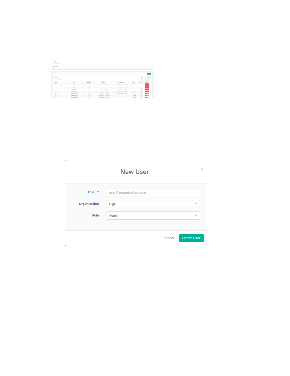
The Users page displays all user accounts under the current user can manage. Authorized users can
create new users and modify any existing user.
Create a new user
To create a new user:
1. From the navigation panel, click Users.
The Uses page appears.
2. Click Create.
The New User dialog appears.
3. For Email, type the user's email address.
4. For Organization, select the appropriate organization for the user.
See Organizations for more information about organizations.
5. For Role, select the appropriate role for the user.
See Roles for further information about roles.
6. Click Create User.
When a new user is created, aView will send a welcome email to the user's email address with
instructions for setting up their password and account. The user must set up their password and
account within 72 hours after the email has been sent. If the user does not respond in time, their
account will need to be recreated.
Digi aView User Guide
40
Page 41
Site navigation Users
Edit a user
To edit a user:
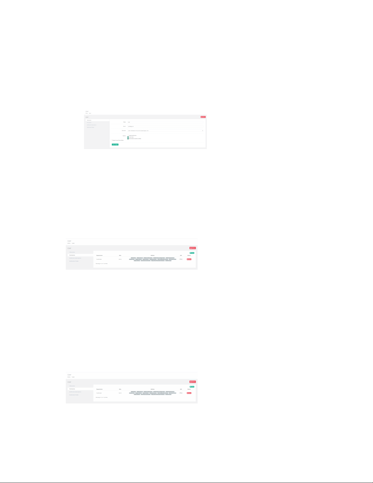
1. From the navigation panel, click Users.
The Uses page appears.
2. Click Edit on the right hand side of a user’s row.
The User Detail page appears.
3. Click Save Changes after completing your changes to the user information.
See Manage User Preferences for information about the remaining tabs one the User Details page.
Manage users
Users are given specific access and abilities by their organization administrator or the administrator
of an organization above them. The abilities and access to certain areas of the aView site are called
user "permissions". A permission could include features such as being able to send remote
commands, move devices to other organizations, deploy/undeploy devices, and having access to view
certain categories of devices.
To manage the permissions a user has, navigate to the Users page, click the Edit pencil icon in the row
of the desired user, and then click the Permissions tab. New permissions can be added by clicking the
Create plus icon, selecting the new permission from the drop-down list, and then click Create
Permission. Note that the list of available permissions are based on the permissions of the user who is
managing the user and the permissions available in the user's organization. To remove a permission
from a user, click the Delete link.
Permissions
Users are given specific access and abilities by an administrator. The abilities and access to certain
areas of the aView application are referred to as user permissions. A permission could include
features such the ability to send remote commands, move devices to other organizations,
deploy/undeploy devices, and having access to view certain categories of devices.
To manage a user's permissions:
Digi aView User Guide
41
Page 42

Site navigation Users
1. From the navigation panel, click Users.
The Uses page appears.
2. Click Edit on the right hand side of a user’s row.
The User Detail page appears.
3. Click Permissions.
The Permissions tab appears.
4. To delete a permission associated with the user, click Delete on the right hand side of the row
associated with the permission.
5. To add a permission to the user:
a. Click Create.
b. Select the appropriate Organization.
c. Select the Role that should be assigned to the user.
Roles are created at the organization level. See Roles for further information about
roles, including how to create them.
6. Click Create Permission.
Digi aView User Guide
42
Page 43

Monitoring devices
About monitoring devices 44
Color indicators 44
Deploy a device 44
Digi aView User Guide
43
Page 44

Monitoring devices About monitoring devices
About monitoring devices
Device monitoring in aView is controlled by the state of the device. The two states a device can be in
are deployed and undeployed.
n Deployed state: Indicates that the device should be monitored based on the events that are
sent in by the device, and will be listed with a particular status (see Color indicators for
information about deployed device statuses). A device that is deployed will also generate
notification alerts, based on the events received and the aView application's access to that
device.
n Undeployed state: Indicates that the device should not be monitored. Undeployed devices will
be listed with a pause icon () as their status and with a dark gray status color. aView will still
list details and events for undeployed devices, but these events will not generate any
notification alerts.
Color indicators
aView marks deployed devices with a color indicator to provide a visual way to note what its status is.
Below is a list of color statuses and their meaning.
n Green: The device is online and is reachable through the aView system. For details on what
triggers a device to go up, refer to the Notification Profiles section of this guide.
n Red: The device is down. This status is also referred to as the Alert status. For details on
what triggers a device to go down, refer to the Notification Profiles section of this guide.
n Blue: The device is running on a backup WAN connection. This indicates that the device's
current WAN connection is one of its backup connections (i.e. not WAN1).
Note The blue status only applies to Gateway devices.
n Orange: The device is in dual-WAN modem, but only its WAN1 connection is online. The
secondary WAN interface is down.
Note The orange status only applies to Gateway devices.
n Gray: The device is inactive, meaning that it has never checked in to aView. This is the state
of the device if it is deployed, but no event has ever been received by aView.
Deploy a device
To deploy an individual device, go to the device details page. This can be done by searching for the
device's MAC address in the search bar, then clicking on the MAC address of the correct device in the
results. Once on the details page, click on the Actions drop-down on the right side of the page and
select Deploy.
Immediately after a device is deployed, aView will automatically send a remote command to the
device to get its current status. This ensures that the status of the device is correctly reflected in
aView.
Digi aView User Guide
44
Page 45

Cellular devices
About cellular devices 46
Cellular device details 46
Cellular device remote commands 50
Cellular configuration requirements for aView 51
Digi aView User Guide
45
Page 46
Cellular devices About cellular devices
About cellular devices
Cellular devices refer to a subset of the Digi Cellular Extender line of products. Supported models are
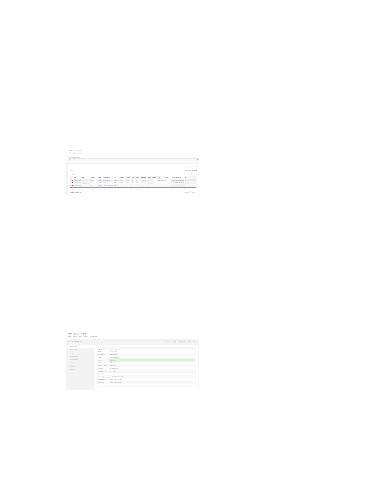
listed below. You can find a list of all the Cellular devices that you have access to by clicking on the
Devices tab in the navigation bar, and then selecting the Cellular link from the dropdown.
n 6300-CX
n 6300-LX
n 635x-SR
n 633x-MX
n 6310-DX
n IX14
Cellular devices are listed in tabular form. The majority of the details are applicable to all device
categories. See Device details page for details on those table entries.
The table entries specific to Cellular devices are:
n Carrier: The cellular carrier of the current connection, indicating the owner of the local cellular
network and modem tower.
n Provider: The cellular provider of the current connection, indicating who provisioned the SIM
card.
n dBm: The signal strength of the cellular connection measured in dBm.
n Signal: The signal strength percentage of the cellular connection.
n Network: The technology type of the cellular connection.
n Phone Number: The phone number of the current cellular connection.
Cellular device details
The majority of details provided on the Cellular device details page are applicable to all categories of
devices. See Device details page for details on those table entries.
The device details specific to Cellular devices are:
Digi aView User Guide
46
Page 47

Cellular devices Cellular device details
n Management IP: The IP address of the Cellular device's aView IPSec tunnel. If this IP does not
match the aView tunnel IP address listed in the local web UI of the Cellular device, a user with
the ability to modify devices can edit the Management IP address.
n Uplink IP Address: The IP address of the current WAN network connection of the Cellular
device.
n Primary Interface: The currently used WAN connection interface.
Cellular device Configuration tab
Cellular devices are configured through the aView site. See Create a new Cellular device configuration
profile for further information.
Cellular device Settings tab
The majority of details provided on the Cellular Settings tab are applicable to all categories of devices.
See Settings tab for details on those table entries.
The device details specific to Cellular devices are:
n Data Plan: The data plan assigned to the device. If the user has the ability to change the data
plan, a drop-down will be displayed and lists the available data plans for the organization the
device belongs to. Once a data plan is associated with the device, any cellular data used by the
device will be tracked in the data plan, which can be viewed and managed by clicking the Edit
button for an Organization (see Organizations). You also have the option of creating a new data
plan if desired.
Cellular device Associated Devices tab
This tab lists any devices that the Cellular device has associated with, indicating that they are
connected to each other. The tab will include the following details about the associated device:
n Device ID: The identifying MAC address for the associated device.
n Model: If the associated device is a type of device supported by ARMT, this entry will display the
type of device ARMT knows it as. If the device is not supported by ARMT, the category will be
listed with a dash ( - ).
n Interface: The physical interface of the Cellular device the associated device is connected to.
n Type: How the associated device is connected to the Cellular device. For example, a type listed
as LAN indicates that the associated device is connected to one of the Cellular device's LAN
Ethernet ports.
n IP Address: The IP address of the associated device.
n Connected: Indicates when the device association was made and how long the associated
device has been connected to the Cellular device.
Cellular device Cellular Details tab
The Cellular Details tab lists details for the Cellular modem. The name of the cellular modem is listed
in the title bar of the Cellular Details tab. If a cellular device has multiple modems, there will be
multiple modem panels, each one corresponding to one of the cellular device's modems. A modem
entry can be removed by clicking the red trash icon at the top-right of the specific tab.
Digi aView User Guide
47
Page 48

Cellular devices Cellular device details
n Carrier: The cellular provider of the modem.
n SKU: The stock keeping unit of the modem.
n Signal Strength: The current RSSI signal strength value, measured in dBm, and percentage of
the modem.
n Signal Bars: The current signal bars, based on the signal strength.
n Speed Test: The five most recent (if any) speed tests performed on the device. Speed tests are
generated by sending a Speed Test command to the device.
Note In order to minimize the speed test's impact on cellular data consumption, the results
are an estimation of the available throughput of the device, and may not represent the full
network speed available.
n Phone Number: The phone number of the modem.
n RSSI: The Received Signal Strength Indicator (RSSI) of the modem. RSSI provides information
about total received wide-band power, including signal interference and thermal noise.
n RSRP: An LTE-specific value, representing the Reference Signal Received Power of the modem.
RSRP is the average power of resource elements that carry cellular specific reference signals
over the entire bandwidth.
n RSRQ: An LTE-specific value, representing the Reference Signal Receive Quality (RSRQ) of the
modem. RSRQ is a combination of RSSI and RSRP and indicates the quality of the received
reference signal.
n SiNR: The signal-to-interference-plus-noise ratio of the modem.
n SNR: The signal-to-noise ratio of the modem.
n IMEI: The IMEI value of the modem.
n ESN: The ESN value of the modem. Note that the ESN value only applies to CDMA cellular
networks.
n ICCID: The ICCID value of the SIM card used by the modem.
n IMSI: The IMSI value of the modem.
n Revision: The hardware version of the modem.
n APN: The APN that the modem is currently connected with. Note that not all modems require
an APN.
n ECIO: The signal-to-noise ratio of the modem. The lower the Ec/Io value, the greater the noise.
n CNTI: The technology type that the modem is currently connected to.
n Band: The frequency or type of cellular band the modem is currently connected to.
n CID: The CID identifier of the modem's current connection.
n LAC: The LAC identifier of the modem's current connection.
n MCC: The mobile country code of the modem's current connection.
n MNC: The mobile network code of the modem's current connection.
n PLMN: The PLMN ID of the modem's current connection, which is a combination of the MCC and
MNC values.
n USB Speed: The speed of the USB port(s) on the Remote Manager device, measured in Mbps.
480 indicates USB 2.0 High Speed and 12 indicates USB 2.0 Full Speed.
Digi aView User Guide
48
Page 49
Cellular devices Cellular device details
Cellular utilization chart
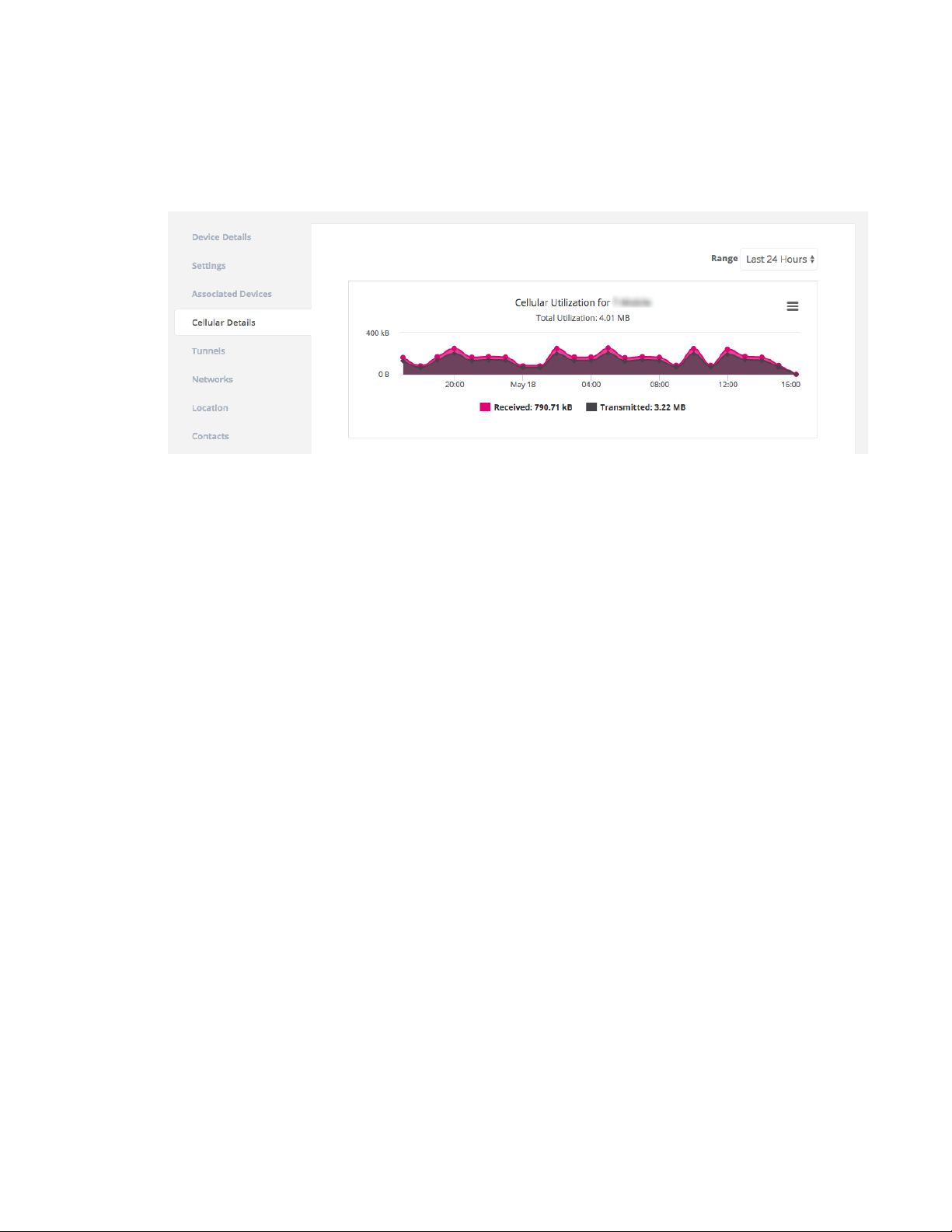
If the device supports a cellular modem, a cellular utilization chart will be displayed. The chart shows
the amount of cellular data used by the device. The initial timespan will display the data usage for the
past 24 hours. You can select different timespans from the Range drop-down.
Cellular device Tunnels tab
The Tunnel tab lists status for any IPSec tunnels established by the Cellular device. Each row of the
tab indicates a unique IPSec tunnel of the device.
n Name: The name of the IPSec tunnel, as specified in the configuration of the Cellular device.
n Status: Indicates whether or not the Cellular device has established the IPSec tunnel.
n Last Updated: The last time aView received an update concerning this tunnel.
n IpLocal: The tunnel IP address assigned to the Cellular device.
n IpRemote: The IP address of the server that the Cellular device built a tunnel to.
n NetLocal: The network settings on the Cellular device for the tunnel.
n NetRemote: The network settings on the server for the tunnel.
Cellular device Network tab
The Network tab lists details for network interfaces that belong to the Cellular device. If an Cellular
device has multiple networks, there will be multiple network tabs, each one corresponding to one of
the device's networks.
n Connection Type: the type of network connection for the interface.
n Priority: Indicates if the network connection is the current primary or alternate connection.
n IP Ranges: The IP addressing for the network.
n Metric: The priority level of the network interface. The lower the number, the higher in priority
the interface.
n MTU: The MTU size of the network interface.
n Gateway IP: The default route (gateway IP) of the network interface.
n Bytes Received: The total amount of data received, measured in bytes, on the network
interface since the Cellular device has been online (resets on reboot).
Digi aView User Guide
49
Page 50

Cellular devices Cellular device remote commands
n Bytes Transmitted: The total amount of data transmitted, measured in bytes, on the network
interface since the Cellular device has been online (resets on reboot).
n Ethernet Speed: If the network type is an Ethernet interface, then this indicates the speed of
the Ethernet port.
n Ethernet Status: If the network type is an Ethernet interface, then this indicates the status of
the physical connection on the Ethernet port.
Cellular device remote commands
Remote commands are sent to a Cellular device through an IPSEC tunnel the device establishes to the
Accelerated remote control server, or through the upstream IP address of the device if no tunnel IP is
available. All Cellular devices by default establish an IPSec tunnel to remote.accns.com. See aView
tunnel alternatives for information about additional IPSec tunnel endpoints.
The tunnel IP address for the Cellular device is stored in aView as the Management IP on the Device
Details tab. If the Management IP is not known, then aView will use the IP address listed in the
Uplink IP Address field on the Device Details tab for sending remote commands.
When you send a remote command to a device, aView utilizes a DNS service running on the remote
control server to verify what tunnel IP address is associated with the device. If the DNS service
responds with a valid IP address, aView will send the remote command to that IP address, otherwise
it will use the known Management IP or the Uplink IP Address if the Management IP is unknown. If the
IP address returned by the DNS service differs than the Management IP listed for the device, aView
will update the Management IP after successfully sending the remote command to the device.
Before sending the remote command to the Cellular device, aView will prompt the user to provide the
device-level username and password to authenticate with the device. If you do not know the
username or password for the device, navigate to the Configuration tab of the device in aView and
select Authentication > Users. Select a user name to change the password. You can also change the
password locally on the device by following the instructions in the device's user manual. For example,
to view instructions for the EX15, visit
https://www.digi.com/resources/documentation/digidocs/90002344/default.htm#os/user-localchange-pswd-t.htm.
Once the username and password are provided for the device, aView will then perform a HTTP
request to the device to validate that the correct device is at the given IP address. If the correct
device is reached and authenticated, the remote command will be sent.
The available remote commands that can be sent to Cellular devices are:
n Check status: The Cellular device will immediately send its current status.
n Check signal strength: The Cellular device will send its signal strength and network info once
every 10 seconds for the next 15 minutes.
n Perform Speed Test: The Cellular device will perform a speed test and send the
Upload/Download results.
Note In order to minimize the speed test's impact on cellular data consumption, the results
are an estimation of the available throughput of the device, and may not represent the full
network speed available.
n ARPing Attached Device: The Cellular device will attempt to ARPing the client device attached
to its Ethernet port.
n Send Wake-on-LAN to Attached Device: The Cellular device will send a wake-on-LAN packet
to the client device attached to its Ethernet port.
Digi aView User Guide
50
Page 51

Cellular devices Cellular configuration requirements for aView
n Check Configuration: The Cellular device will immediately pull its configuration and reboot to
apply any new settings.
n Update Modem Firmware: The Cellular device will query the Digi firmware server. If a new
version of firmware is found for the active firmware used on the embedded modem in the
Cellular device, it will download the new firmware and update the embedded modem. Note the
Cellular device must be running firmware version 17.8.128 or higher to process this command.
n Reboot: Reboot the Cellular device.
Cellular device emergency SMS commands
As an alternative to the Remote commands, you can also send commands via SMS messaging to a
Cellular device. The SIM card used by the Cellular device must have SMS enabled, or you will not be
able to send SMS commands.
The available SMS commands that can be sent are:
n Set Configuration: A pop-up window appears where a user can enter in a configuration option
or set of options to apply to the Cellular device. Multiple config options must be separated by a
comma. For example, if a user wants to set the APN of a Cellular device to managedvpn, they
would enter "modem_apn=managedvpn".
n Configuration Reset: Restore default configuration on the Cellular device and reboot.
n Firmware Reset: Restore to the backup firmware image on the Cellular device, and reboot.
n Factory Reset: Restore default configuration on the Cellular device, restore to the backup
firmware image, and reboot.
n Remote Control: Tell the Cellular device to bring up its remote control tunnel (useful if on low
data plan, so the remote control tunnel is not always up using data).
n Reboot: Reboot the Cellular device.
Cellular configuration requirements for aView
In order for the aView site to monitor a Cellular device, it must send its syslogs to the aView syslog
server IP address, the domain of which is logs.accns.com.
For a Cellular device to get its configuration from the aView site, it must be set to pull its configuration
from the aView configuration server configuration.accns.com. The device must also be able to sync its
date and time with an NTP server; the default is time.accns.com.
In the device configuration, ensure the following options are set in Service > Web administration:
n Enable is selected.
n Port is set to 443.
n Access control list -> Zones includes the IPSec zone.
This zone is included by default, but it's mentioned here for the user to verify that it is still
present, in case the device is running settings that deviate from the default configuration.
Digi aView User Guide
51
Page 52
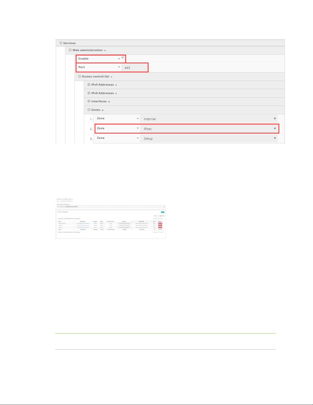
Cellular devices Cellular configuration requirements for aView
View Cellular configuration profiles
To view the current list of group configuration profiles a user has access to:
1. Click on the Configurations button in the navigation panel.
2. Select Cellular in the drop-down.
Create a new Cellular device configuration profile
To create a new group configuration profile:
1. Click on the Configurations button in the navigation panel.
2. Select Cellular in the drop-down.
3. Click the plus icon located at the top right of the window.
4. Select the firmware version. The appropriate configuration schema will automatically load.
5. Set any desired settings in the presented configuration schema. Hovering your mouse over the
name for a configuration option will display a pop-up providing help details about that option,
including any default values. Once all the desired configuration options have been specified,
click Create.
Note If the desired firmware is not listed, it must be uploaded onto the firmware management
service, which is hosted at distro.accns.com.
Digi aView User Guide
52
Page 53
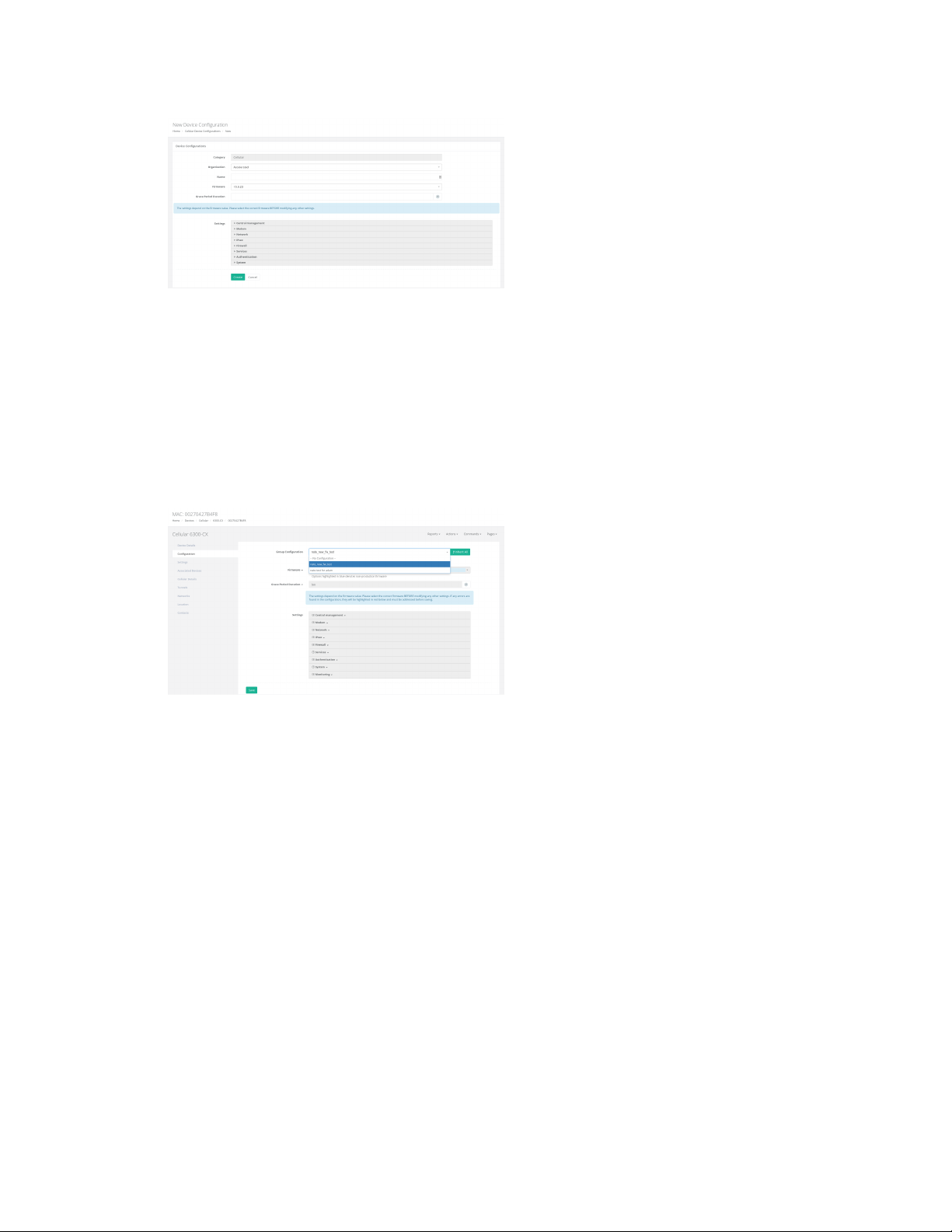
Cellular devices Cellular configuration requirements for aView
Apply a Cellular configuration profile
To apply a group configuration profile to a Cellular device:
1. Go to the device details page for the specific device. This can be done by searching for the
device's MAC address in the search bar, then clicking on the MAC address of the correct device
in the results.
2. Once on the details page, click on the Configuration tab, select the new configuration profile
from the Group Configuration drop-down, and click the Save button.
Individual device configuration settings
In addition to applying a group configuration profile to a device, authorized users will also have the
option of setting configuration options to apply only to an individual device. These individual device
configuration options are listed in the Configuration tab, below the Group Configuration option.
When a new group configuration is selected for a device, a list of inherited configuration settings from
that group configuration profile will be displayed. Authorized users can then click on any setting and
select the Override option to change the selected configuration option. It is important to note that
any configuration option overridden in this way will only apply to that individual device. Any other
devices that are linked to the same group configuration will only receive configuration settings from
the group configuration profile, not any of the overridden settings from another individual device's
configuration.
n Inherit All: This button can be used to reset an individual device's configuration back to the
group configuration profile's settings. Any configuration options previously overridden in the
individual device configuration will be undone and reset back to the settings inside the group
configuration.
Digi aView User Guide
53
Page 54

Cellular devices Cellular configuration requirements for aView
Delete a Cellular device configuration profile
Group configuration profiles can be deleted by clicking on the Delete icon for the appropriate profile on
the Cellular Configurations page. A confirmation pop-up will ask the user to confirm that they wish to
delete the configuration profile. If there are any devices linked to the configuration profile that is
being deleted, the profile will not be deleted. The user must first unlink the configuration profile from
the device and then they can remove the profile.
Digi aView User Guide
54
Page 55

Dial-to-IP devices
About dial-to-IP devices 56
Dial-to-IP device details 56
View Dial-to-IP configuration profiles 59
Create a new Dial-to-IP device configuration profile 60
Apply a Dial-to-IP configuration profile 60
Individual device configuration settings 61
Delete a Dial-to-IP device configuration profile 61
Digi aView User Guide
55
Page 56
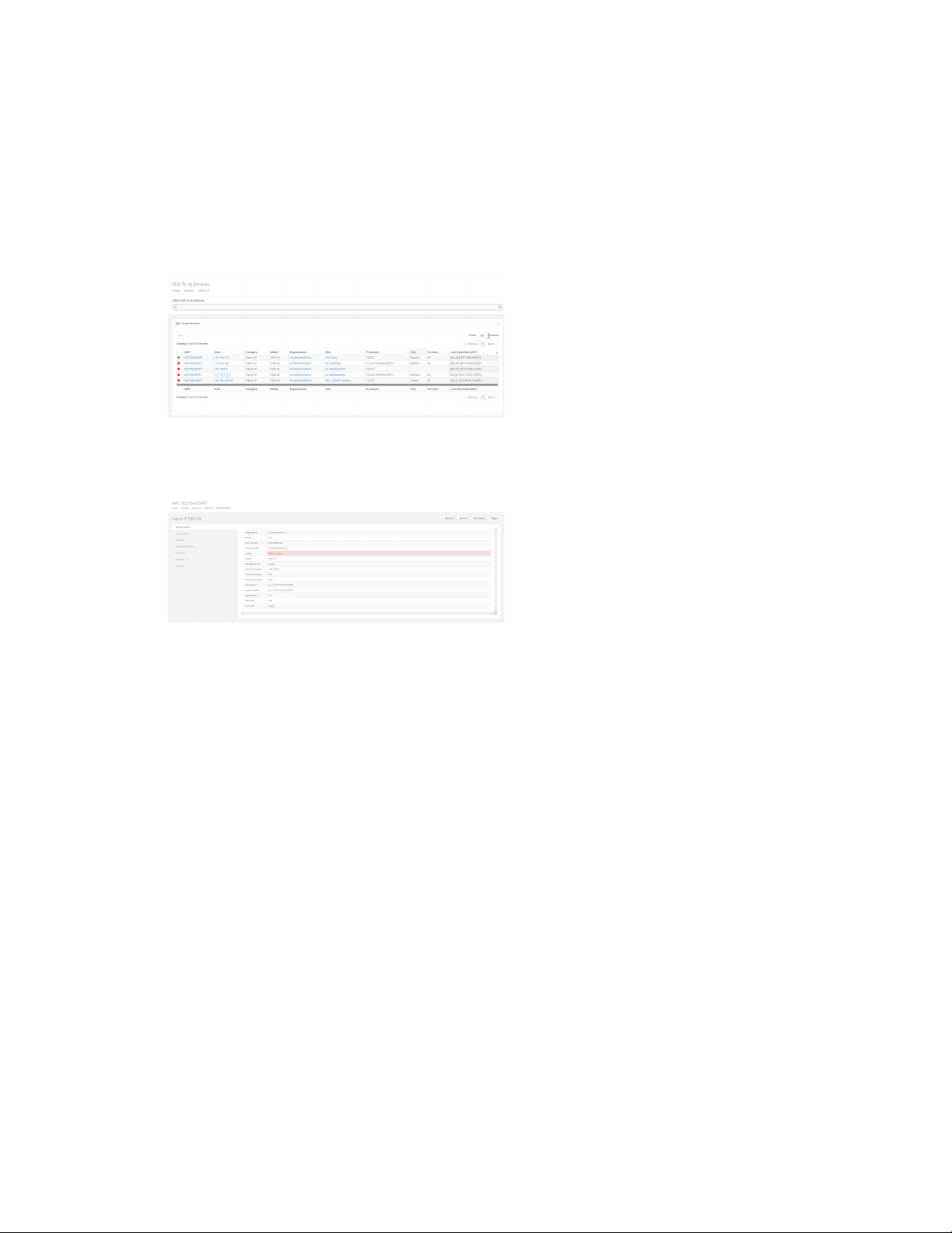
Dial-to-IP devices About dial-to-IP devices
About dial-to-IP devices
Dial-to-IP devices refer to the Digi Dial-to-IP Converter line of products. You can find a list of all the
Dial-to-IP devices that you have access to by clicking Devices in the navigation bar, and then selecting
Dial-to-IP. Supported models are:
n 5300-DC
n 5301-DC
Dial-to-IP device details
The majority of details provided on the Dial-to-IP device details page are applicable to all categories of
devices. See Device details page for details on those table entries.
The following are device details specific to Dial-to-IP devices:
n Management IP: The IP address of the Dial-to-IP device's aView IPSec tunnel. If this IP does
not match the aView tunnel IP address listed in the local web UI of the Dial-to-IP device, a user
with the ability to modify devices can edit the Management IP address.
n Uplink IP Address: The IP address of the current WAN network connection of the Dial-to-IP
device.
n Primary Interface: The currently used WAN connection interface.
Dial-to-IP device Configuration tab
Dial-to-IP devices are configured through the aView site. See Create a new Dial-to-IP device
configuration profile for further information.
Dial-to-IP device Associated Devices tab
This tab lists any devices that the Dial-to-IP device has associated with, indicating that they are
connected to each other. The tab will include the following details about the associated device.
Digi aView User Guide
56
Page 57

Dial-to-IP devices Dial-to-IP device details
n Device ID: The identifying MAC address for the associated device.
n Model: If the associated device is a type of device supported by ARMT, this entry will display the
type of device ARMT knows it as. If the device is not supported by ARMT, the category will be
listed with a dash ( - ).
n Interface: The physical interface of the Dial-to-IP device the associated device is connected to.
n Type: How the associated device is connected to the Dial-to-IP device. For example, a type
listed as WAN indicates that the associated device is connected to one of the Dial-to-IP device's
WAN Ethernet ports.
n IP Address: The IP address of the associated device.
n Connected: Indicates when the device association was made and how long the associated
device has been connected to the Dial-to-IP device.
Dial-to-IP device Tunnels tab
The Tunnel tab lists status for any IPSec tunnels established by the Dial-to-IP device. Each row of the
tab indicates a unique IPSec tunnel of the device.
n Name: The name of the IPSec tunnel, as specified in the configuration of the Dial-to-IP device.
n Status: Indicates whether or not the Dial-to-IP device has established the IPSec tunnel.
n Last Updated: The last time aView received an update concerning this tunnel.
n IpLocal: The tunnel IP address assigned to the Dial-to-IP device.
n IpRemote: The IP address of the server that the Dial-to-IP device built a tunnel to.
n NetLocal: The network settings on the Dial-to-IP device for the tunnel.
n NetRemote: The network settings on the server for the tunnel.
Dial-to-IP device Network tab
The Network tab lists details for network interfaces that belong to the Dial-to-IP device. If a Dial-to-IP
device has multiple networks, there will be multiple network tabs, each one corresponding to one of
the device's networks.
n Connection Type: the type of network connection for the interface.
n Priority: Indicates if the network connection is the current primary or alternate connection.
n IP Ranges: The IP addressing for the network.
n MTU: The MTU size of the network interface.
n Gateway IP: The default route (gateway IP) of the network interface.
n Bytes Received: The total amount of data received, measured in bytes, on the network
interface since the Dial-to-IP device has been online (resets on reboot).
n Bytes Transmitted: The total amount of data transmitted, measured in bytes, on the network
interface since the Dial-to-IP device has been online (resets on reboot).
n Ethernet Speed: If the network type is an Ethernet interface, then this indicates the speed of
the Ethernet port.
n Ethernet Status: If the network type is an Ethernet interface, then this indicates the status of
the physical connection on the Ethernet port.
Digi aView User Guide
57
Page 58

Dial-to-IP devices Dial-to-IP device details
Dail-to-IP device remote commands
Remote commands are sent to a Dail-to-IP device through an IPSEC tunnel the device establishes to
the Accelerated remote control server, or through the upstream IP address of the device if no tunnel
IP is available. All Dail-to-IP devices by default establish an IPSec tunnel to remote.accns.com. See
aView tunnel alternatives for information about additional IPSec tunnel endpoints.
The tunnel IP address for the Dail-to-IP device is stored in aView as the Management IP on the Device
Details tab. If the Management IP is not known, then aView will use the IP address listed in the
Uplink IP Address field on the Device Details tab for sending remote commands.
When you send a remote command to a device, aView utilizes a DNS service running on the remote
control server to verify what tunnel IP address is associated with the device. If the DNS service
responds with a valid IP address, aView will send the remote command to that IP address, otherwise
it will use the known Management IP or the Uplink IP Address if the Management IP is unknown. If the
IP address returned by the DNS service differs than the Management IP listed for the device, aView
will update the Management IP after successfully sending the remote command to the device.
Before sending the remote command to the Dail-to-IP device, aView will prompt the user to provide
the device-level username and password to authenticate with the device. If you do not know the
username or password for the device, navigate to the Configuration tab of the device in aView and
select Authentication > Users. Select a user name to change the password. You can also change the
password locally on the device by following the instructions in the device's user manual. For example,
to view instructions for the EX15, visit
https://www.digi.com/resources/documentation/digidocs/90002344/default.htm#os/user-localchange-pswd-t.htm.
Once the username and password are provided for the device, aView will then perform a HTTP
request to the device to validate that the correct device is at the given IP address. If the correct
device is reached and authenticated, the remote command will be sent.
The available remote commands that can be sent to Dail-to-IP devices are:
n Check status: The Dial-to-IP device will immediately send its current status.
n Check signal strength: The Dial-to-IP device will send its signal strength and network info
once every 10 seconds for the next 15 minutes.
n Perform Speed Test: The Dial-to-IP device will perform a speed test and send the
Upload/Download results.
n ARPing Attached Device: The Dial-to-IP device will attempt to ARPing the client device
attached to its Ethernet port.
n Send Wake-on-LAN to Attached Device: The Dial-to-IP device will send a wake-on-LAN packet
to the client device attached to its Ethernet port.
n Check Configuration: The Dial-to-IP device will immediately pull its configuration and reboot
to apply any new settings.
n Reboot: Reboot the Dial-to-IP device.
Dial-to-IP device emergency SMS commands
As an alternative to the Remote commands, you can also send commands via SMS messaging to a
Dial-to-IP device. The SIM card used by the Dial-to-IP device must have SMS enabled, or you will not be
able to send SMS commands.
The available SMS commands that can be sent are:
n Set Configuration: A pop-up window appears where a user can enter in a configuration option
or set of options to apply to the Dial-to-IP device. Multiple config options must be separated by
Digi aView User Guide
58
Page 59
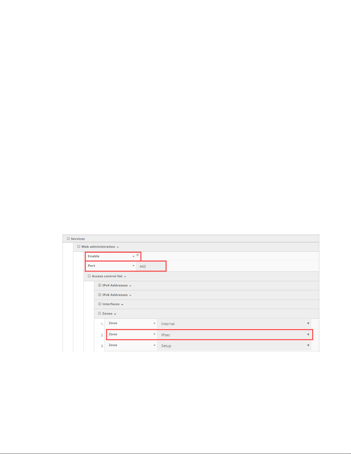
Dial-to-IP devices View Dial-to-IP configuration profiles
a comma. For example, if a user wants to set the APN of a Dial-to-IP device to managedvpn,
they would enter "modem_apn=managedvpn".
n Configuration Reset: Restore default configuration on the Dial-to-IP device and reboot.
n Firmware Reset: Restore to the backup firmware image on the Dial-to-IP device, and reboot.
n Factory Reset: Restore default configuration on the Dial-to-IP device, restore to the backup
firmware image, and reboot.
n Remote Control: Tell the Dial-to-IP device to bring up its remote control tunnel (useful if on low
data plan, so the remote control tunnel is not always up using data).
n Reboot: Reboot the Dial-to-IP device.
Dial-to_IP configuration requirements for aView
In order for the aView site to monitor a Dial-to_IP device, it must send its syslogs to the aView syslog
server IP address, the domain of which is logs.accns.com.
For a Dial-to_IP device to get its configuration from the aView site, it must be set to pull its
configuration from the aView configuration server configuration.accns.com. The device must also be
able to sync its date and time with an NTP server; the default is time.accns.com.
In the device configuration, ensure the following options are set in Service > Web administration:
n Enable is selected.
n Port is set to 443.
n Access control list -> Zones includes the IPSec zone.
This zone is included by default, but it's mentioned here for the user to verify that it is still
present, in case the device is running settings that deviate from the default configuration.
View Dial-to-IP configuration profiles
To view the current list of group configuration profiles a user has access to:
Digi aView User Guide
59
Page 60
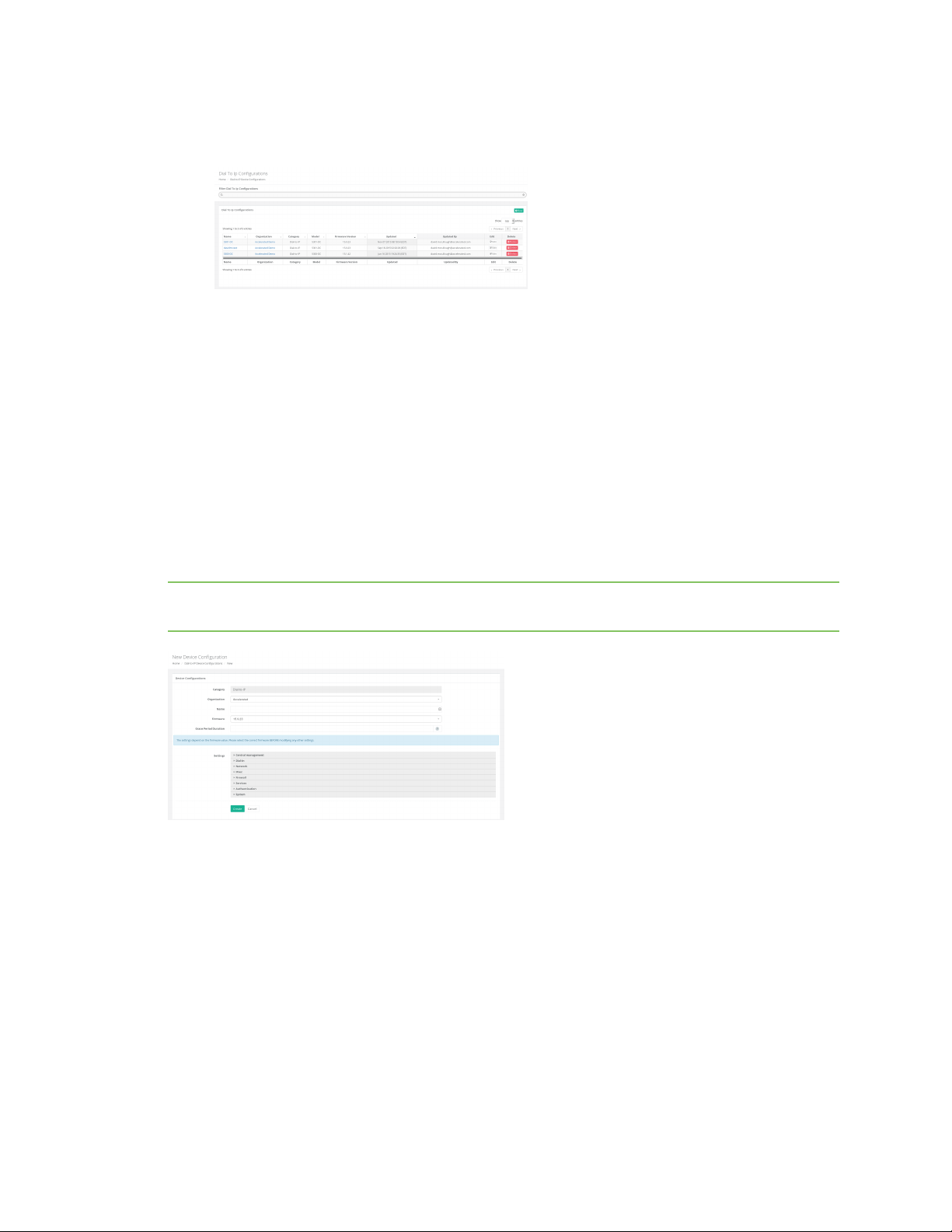
Dial-to-IP devices Create a new Dial-to-IP device configuration profile
1. Click on the Configurations button in the navigation panel.
2. Select Dial-to-IP in the drop-down.
Create a new Dial-to-IP device configuration profile
To create a new group configuration profile:
1. Click on the Configurations button in the navigation panel.
2. Select Dial-to-IP in the drop-down.
3. Click the plus icon located at the top right of the window.
4. Select the firmware version. The appropriate configuration schema will automatically load.
5. Set any desired settings in the presented configuration schema. Hovering your mouse over the
name for a configuration option will display a pop-up providing help details about that option,
including any default values. Once all the desired configuration options have been specified,
click Create.
Note If the desired firmware is not listed, it must be uploaded onto the firmware management
service, which is hosted at distro.accns.com.
Apply a Dial-to-IP configuration profile
To apply a group configuration profile to a Dial-to-IP device:
1. Go to the device details page for the specific device. This can be done by searching for the
device's MAC address in the search bar, then clicking on the MAC address of the correct device
in the results.
2. Once on the details page, click on the Configuration tab, select the new configuration profile
from the Group Configuration drop-down, and click the Save button.
Digi aView User Guide
60
Page 61

Dial-to-IP devices Individual device configuration settings
Individual device configuration settings
In addition to applying a group configuration profile to a device, authorized users will also have the
option of setting configuration options to apply only to an individual device. These individual device
configuration options are listed in the Configuration tab, below the Group Configuration option.
When a new group configuration is selected for a device, a list of inherited configuration settings from
that group configuration profile will be displayed. Authorized users can then click on any setting and
select the Override option to change the selected configuration option. It is important to note that
any configuration option overridden in this way will only apply to that individual device. Any other
devices that are linked to the same group configuration will only receive configuration settings from
the group configuration profile, not any of the overridden settings from another individual device's
configuration.
n Inherit All: This button can be used to reset an individual device's configuration back to the
group configuration profile's settings. Any configuration options previously overridden in the
individual device configuration will be undone and reset back to the settings inside the group
configuration.
Delete a Dial-to-IP device configuration profile
To delete group configuration profiles:
1. From the Navigation bar, select Configurations > Dial-to-IP.
The Dial-to-IP Configurations page displays.
2. Click Delete for the appropriate Dial-to-IP configuration profile.
3. Click OK to confirm.
If there are any devices linked to the configuration profile that is being deleted, the profile will not be
deleted. You must first unlink the configuration profile from the device and then delete the profile. See
Apply a Dial-to-IP configuration profile for information about changing a device's configuration profile.
Digi aView User Guide
61
Page 62

Legacy cellular devices
About legacy cellular devices 63
Legacy cellular device details 63
Remote commands 66
Legacy Cellular configuration requirements for aView 67
Digi aView User Guide
62
Page 63
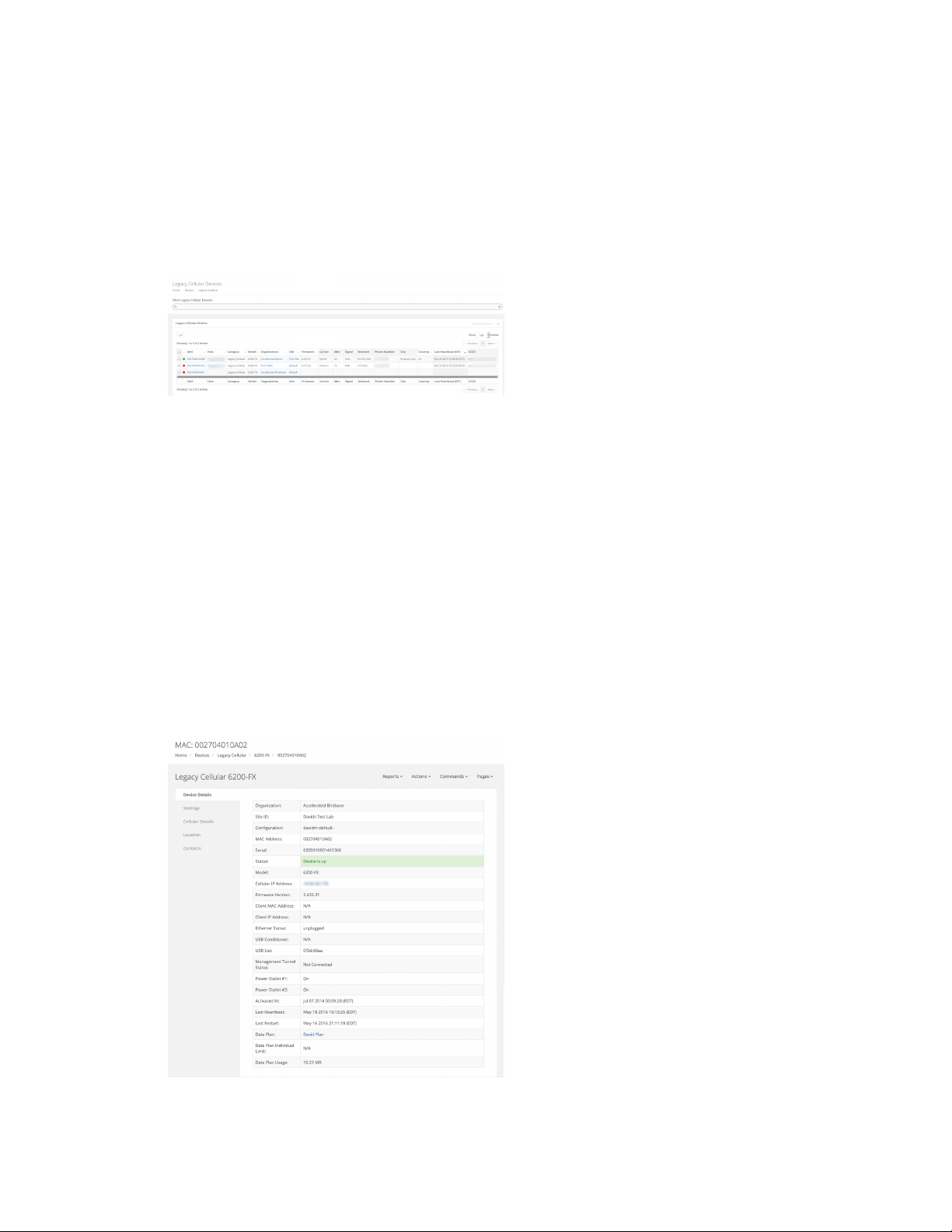
Legacy cellular devices About legacy cellular devices
About legacy cellular devices
Legacy Cellular devices refer to the Digi Cellular Extender line of products. Supported models are
listed below. A user can find a list of all the cellular devices they have access to by clicking on the
Devices tab in the navigation bar, and then select the Cellular link from the drop-down.
n 6200-FX
n NetBridge-SX
Legacy Cellular devices are listed in tabular form. The majority of the details are applicable to all
device categories. See Device details page for details on those table entries.
The table entries specific to cellular devices are:
n Carrier: The cellular carrier of the current connection, indicating the owner of the local cellular
network and modem tower.
n Provider: The cellular provider of the current connection, indicating who provisioned the SIM
card.
n dBm: The RSSI signal strength of the cellular connection measure in dBm.
n Signal: The RSSI signal strength percentage of the cellular connection.
n Network: The technology type of the cellular connection.
n Phone Number: The phone number of the current cellular connection.
Legacy cellular device details
Digi aView User Guide
63
Page 64

Legacy cellular devices Legacy cellular device details
The majority of details provided on the cellular device details page are applicable to all categories of
devices. See Device details page for details on those table entries.
The device details specific to cellular devices are listed below.
n Cellular IP Address: The IP address received when connecting to the cellular network.
n Client MAC Address: The MAC address of the client device (the device connected to the
Cellular Extender's Ethernet port).
n Client IP Address: The IP address the Cellular Extender device assigned to the client device
(the device connected to its Ethernet port).
n Ethernet Status: The status of the physical link on the Ethernet port of the Cellular Extender.
n USB Conditioner: Indicates if a USB Conditioner hub device is connected between the Cellular
Extender and the USB modem.
n USB List: Lists the vendor and product IDs of any USB devices connected to the Cellular
Extender.
n Management Tunnel Status: Indicates whether the remote command IPSec tunnel is up and
active, or disabled. If disabled or down, users will not be able to send remote commands to the
Legacy Cellular Device. Note that SMS commands will still work if the SIM card used by the
Legacy Cellular device has SMS enabled.
Legacy Cellular device Settings tab
The majority of details provided on the Legacy Cellular Settings tab are applicable to all categories of
devices. See Settings tab for details on those table entries.
The device details specific to Legacy Cellular devices are:
n Data Plan: The data plan assigned to the device. If the user has the ability to change the data
plan, a drop-down will be displayed and lists the available data plans for the organization the
device belongs to. Once a data plan is associated with the device, any cellular data used by the
device will be tracked in the data plan, which can be viewed and managed by clicking the Edit
button for an Organization (see Organizations). You also have the option of creating a new data
plan if desired.
Legacy Cellular device Configuration tab
Cellular devices are configured through the aView site. See Create a new Legacy Cellular configuration
profile for further information.
Legacy Cellular Associated device tab
This tab lists any devices that the Legacy Cellular device has associated with, indicating that they are
connected to each other. The tab will include the following details about the associated device.
n Device ID: The identifying MAC address for the associated device.
n Model: If the associated device is a type of device supported by ARMT, this entry will display the
type of device ARMT knows it as. If the device is not supported by ARMT, the category will be
listed with a dash ( - ).
n Interface: The physical interface of the Legacy Cellular device the associated device is
connected to.
Digi aView User Guide
64
Page 65

Legacy cellular devices Legacy cellular device details
n Type: How the associated device is connected to the Legacy Cellular device. For example, a
type listed as LAN indicates that the associated device is connected to one of the Legacy
Cellular device's LAN Ethernet ports.
n IP Address: The IP address of the associated device.
n Connected: Indicates when the device association was made and how long the associated
device has been connected to the Legacy Cellular device.
Legacy Cellular device Cellular details tab
The Cellular Details tab lists details for the cellular modem. The name of the cellular modem is listed
in the title bar of the Cellular Details tab. In the example above, the cellular modem name is
Sierrawireless340u. If a cellular device has multiple modems, there will be multiple tables, each one
corresponding to one of the cellular device's modems. A modem entry can be removed by clicking the
red trash icon at the top-right of the specific tab.
n Carrier: The cellular provider of the modem.
n Signal Strength: The current RSSI signal strength value, measured in dBm, and percentage of
the modem.
n Signal Bars: The current signal bars, based on the signal strength.
n Speed Test: The five most recent (if any) speed tests performed on the device. Speed tests are
generated by sending a Speed Test command to the device.
Note In order to minimize the speed test's impact on cellular data consumption, the results
are an estimation of the available throughput of the device, and may not represent the full
network speed available.
n Phone Number: The phone number of the modem.
n RSSI: The Received Signal Strength Indicator (RSSI) of the modem. RSSI provides information
about total received wide-band power, including signal interference and thermal noise.
n RSRP: An LTE-specific value, representing the Reference Signal Received Power of the modem.
RSRP is the average power of resource elements that carry cellular specific reference signals
over the entire bandwidth.
n RSRQ: An LTE-specific value, representing the Reference Signal Receive Quality (RSRQ) of the
modem. RSRQ is a combination of RSSI and RSRP and indicates the quality of the received
reference signal.
n SiNR: The signal-to-interference-plus-noise ratio of the modem.
n SNR: The signal-to-noise ratio of the modem.
n IMEI: The IMEI value of the modem.
n ESN: The ESN value of the modem. Note that the ESN value only applies to CDMA cellular
networks.
n ICCID: The ICCID value of the modem.
n Revision: The hardware version of the modem.
n APN: The APN that the modem is currently connected with. Note that not all modems require
an APN.
n ECIO: The signal-to-noise ratio of the modem. The lower the Ec/Io value, the greater the noise.
n CNTI: The technology type that the modem is currently connected to.
Digi aView User Guide
65
Page 66
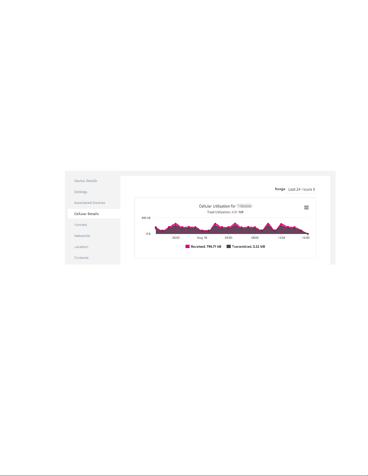
Legacy cellular devices Remote commands
n Band: The frequency or type of cellular band the modem is currently connected to.
n CID: The CID identifier of the modem's current connection.
n LAC: The LAC identifier of the modem's current connection.
n MCC: The mobile country code of the modem's current connection.
n MNC: The mobile network code of the modem's current connection.
n PLMN: The PLMN ID of the modem's current connection, which is a combination of the MCC and
MNC values.
n USB Speed: The speed of the USB port(s) on the Legacy Cellular device, measured in Mbps. 480
indicates USB 2.0 High Speed and 12 indicates USB 2.0 Full Speed.
Cellular utilization chart
If the device supports a cellular modem, a cellular utilization chart will be displayed. The chart shows
the amount of cellular data used by the device. The initial timespan will display the data usage for the
past 24 hours. You can select different timespans from the Range drop-down.
Legacy Cellular device Tunnels tab
The Tunnels tab lists status for any IPSec tunnels established by the Legacy Cellular device. Each row
of the tab indicates a unique IPSec tunnel of the device.
n Name: The name of the IPSec tunnel, as specified in the configuration of the Legacy Cellular
device.
n Status: Indicates whether or not the Legacy Cellular device has established the IPSec tunnel.
Remote commands
Remote commands are sent to a cellular device through an IPsec tunnel the cellular device
establishes to the Digi remote control server. If the remote control IPsec tunnel is disconnected, then
a user will not be able to send remote commands to the cellular device. The available remote
commands that can be sent to cellular devices are listed below.
n Check status: The cellular device will immediately send its current status.
n Check signal strength: The cellular device will send its signal strength and network info once
every 10 seconds for the next 15 minutes.
Digi aView User Guide
66
Page 67

Legacy cellular devices Legacy Cellular configuration requirements for aView
n Perform Speed Test: The cellular device will perform a speed test and send the
Upload/Download results.
Note In order to minimize the speed test's impact on cellular data consumption, the results
are an estimation of the available throughput of the device, and may not represent the full
network speed available.
n ARPing Attached Device: The cellular device will attempt to ARPing the client device attached
to its Ethernet port.
n Send Wake-on-LAN to Attached Device: The cellular device will send a wake-on-LAN packet
to the client device attached to its Ethernet port.
n Check Configuration: The cellular device will immediately pull its configuration and reboot to
apply any new settings.
n Reboot: Reboot the cellular device.
Legacy Cellular device emergency SMS commands
As an alternative to the Remote commands, you can also send commands via SMS messaging to a
Legacy Cellular device. The SIM card used by the Legacy Cellular device must have SMS enabled, or you
will not be able to send SMS commands.
The available SMS commands that can be sent are:
n Set Configuration: A pop-up window appears where a user can enter in a configuration option
or set of options to apply to the Legacy Cellular device. Multiple config options must be
separated by a comma. For example, if a user wants to set the APN of a Legacy Cellular device
to managedvpn, they would enter "modem_apn=managedvpn".
n Configuration Reset: Restore default configuration on the Legacy Cellular device and reboot.
n Firmware Reset: Restore to the backup firmware image on the Legacy Cellular device, and
reboot.
n Factory Reset: Restore default configuration on the Legacy Cellular device, restore to the
backup firmware image, and reboot.
n Remote Control: Tell the Legacy Cellular device to bring up its remote control tunnel (useful if
on low data plan, so the remote control tunnel is not always up using data).
n Reboot: Reboot the Legacy Cellular device.
Remote power commands
If a Remote Power device is connected via serial-to-USB cable to the Cellular Extender, these remote
commands can be used to toggle the power on or off on either of the Remote Power device's outlets.
Legacy Cellular configuration requirements for aView
In order for the aView site to monitor a Legacy Cellular device, it must send its syslogs to the aView
syslog server IP address, the domain of which is logs.accns.com.
For a Legacy Cellular device to get its configuration from the aView site, it must be set to pull its
configuration from the aView configuration server configuration.accns.com. The device must also be
able to sync its date and time with an NTP server; the default is time.accns.com.
In the device configuration, ensure the following options are set in Service > Web administration:
Digi aView User Guide
67
Page 68
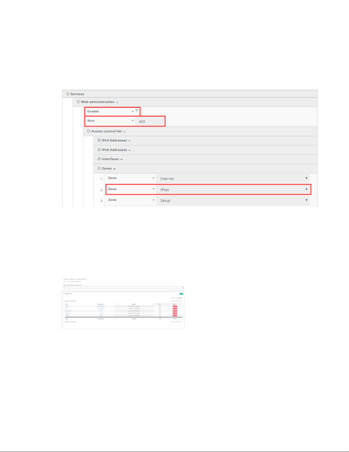
Legacy cellular devices Legacy Cellular configuration requirements for aView
n Enable is selected.
n Port is set to 443.
n Access control list -> Zones includes the IPSec zone.
This zone is included by default, but it's mentioned here for the user to verify that it is still
present, in case the device is running settings that deviate from the default configuration.
Create a new Legacy Cellular configuration profile
Before creating a new cellular configuration profile, first decide if the profile should inherit any
settings from another configuration profile (referred to as the 'parent configuration'). This adds the
benefit of having a structured and/or tiered configuration environment, where a new configuration
inherits all the defaults for an organization, and the user adds the necessary changes to those base
settings. To view the current list of configuration profiles a user has access to, click on the
Configurations button in the navigation panel and then select Legacy Cellular in the drop-down.
To create a new configuration profile, first navigate to the Configurations section of aView by clicking
on the Configurations button in the navigation panel, and then select Legacy Cellular in the dropdown. Next click the plus icon located at the top right of the window to create a new cellular
configuration. Specify a name for the configuration profile and select the desired parent configuration.
If a user does not select a parent configuration, the profile will inherit the system default values for a
cellular device.
Next, enter in any other desired configuration options. Refer to the help boxes for each configuration
option for details on what the option is used for as well as what the default value is for the option.
Required fields are marked with asterisks (*) and any values inherited from the parent configuration
are listed in red. Once all the desired configuration options have been specified, click Create.
Digi aView User Guide
68
Page 69
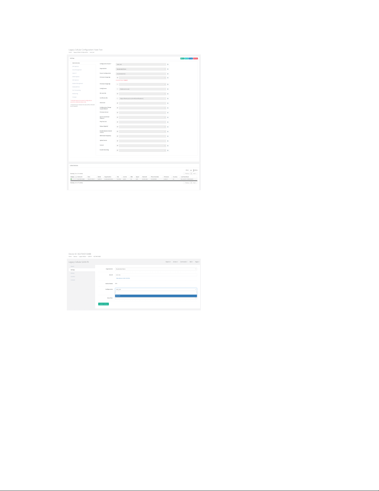
Legacy cellular devices Legacy Cellular configuration requirements for aView
Apply a cellular configuration profile
To apply a configuration profile to a cellular device, go to the device details page for the specific
device. This can be done by searching for the device's MAC address in the search bar, then clicking on
the MAC address of the correct device in the results. Once on the details page, select the new
configuration profile from the Configuration drop-down menu below the Admin panel.
Delete a configuration profile
Configuration profiles can be deleted by selecting the desired configuration name on the Legacy
Cellular Configurations page, then select the Delete Configuration button at the top right of the
profile. Note that if there are any devices linked to the configuration profile that is being deleted, the
profile will not be deleted. You must first unlink the configuration profile from the device and then you
can remove the profile.
Digi aView User Guide
69
Page 70

VPN Gateway devices
About VPN Gateway devices 71
Configure down status for VPN gateway devices 71
VPN Gateway device details 72
VPN Gateway Remote commands 77
VPN Gateway configuration requirements for aView 78
Digi aView User Guide
70
Page 71
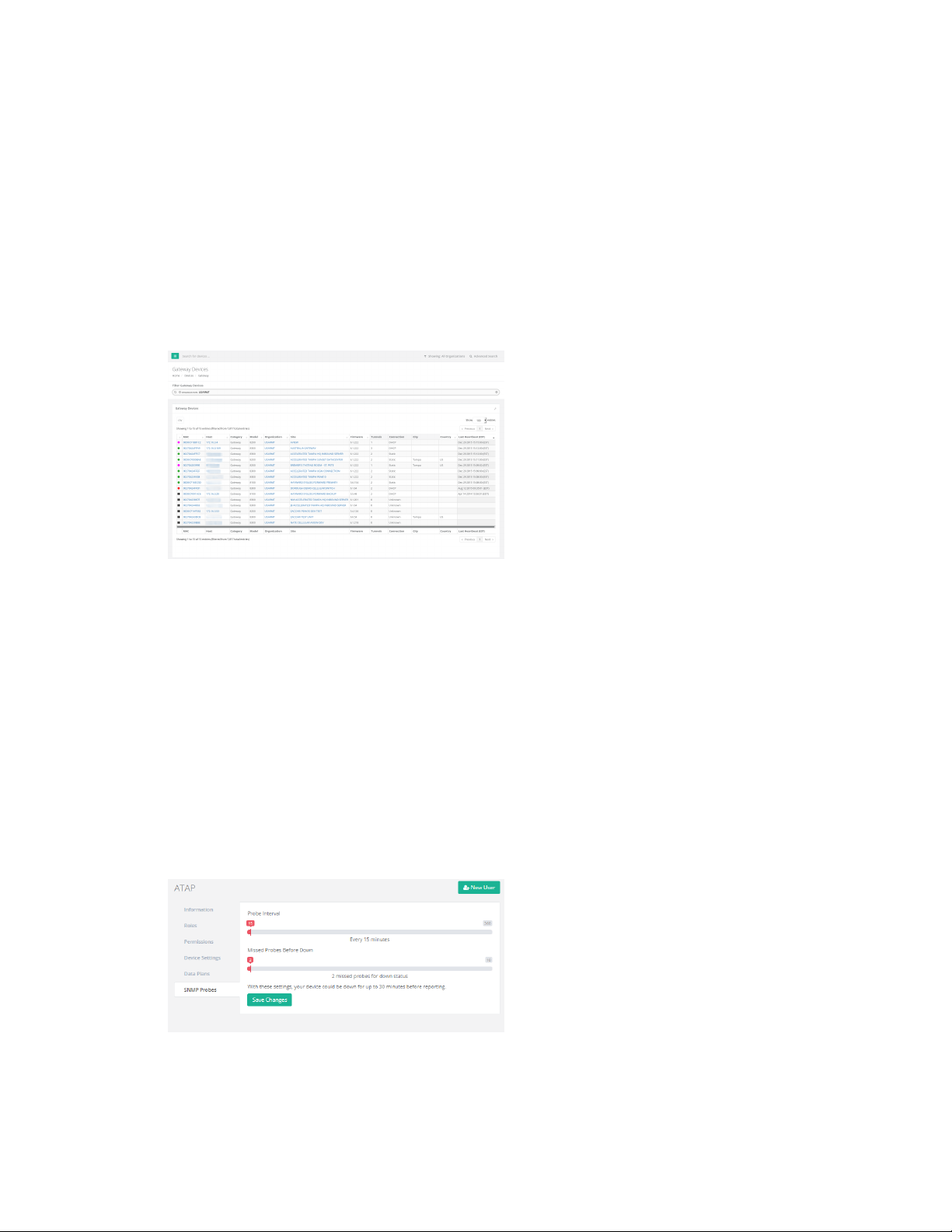
VPN Gateway devices About VPN Gateway devices
About VPN Gateway devices
Gateway devices refer to the AT&T VPN Gateway line of products. Supported models are listed below.
You can find a list of all the Gateway devices you have access to by clicking on the Devices link in the
navigation bar, and then select the Gateway link from the drop-down.
n U115
n U110
n VPN Gateway 8300
n VPN Gateway 8200
n VPN Gateway 8100
Gateway devices are listed in tabular form. The majority of the details are applicable to all device
categories. See Device details page for details on those table entries. The table entries specific to
Gateway devices are:
n Tunnels: The current number of VPN tunnels the Gateway device has up as of when this page
was loaded.
n Connection: The connection currently being used by the Gateway device as of when this page
was loaded.
Configure down status for VPN gateway devices
VPN Gateway devices are monitored by Digi aView using SNMP probes.
Configuring when a Gateway device is considered down (red status) in Digi aView is done by adjusting
the Probe Interval and Missed Probes before Down options in the Organization settings for the
Gateway device. These settings will apply to all devices that belong to that organization.
Digi aView User Guide
71
Page 72
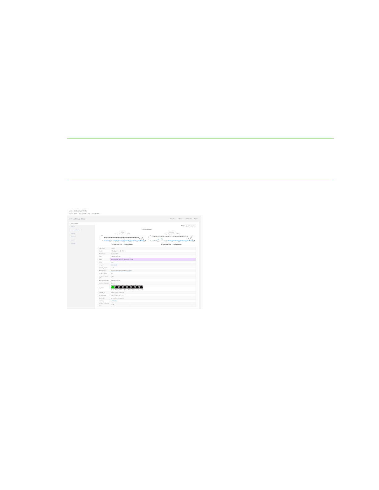
VPN Gateway devices VPN Gateway device details
Probe Interval
The Probe Interval option controls how often Digi aView sends an SNMP probe to the VPN Gateway.
By default, Digi aView probes the VPN Gateway once every 15 minutes. Each probe pulls the most
recent status details from the VPN Gateway and updates the details in Digi aView with the results.
Missed Probes Before Down
The Missed Probes Before Down option controls how many probes can be missed before Digi aView
considers a device as Down. The default number of missed probes is two. When the Missed Probes
Before Down (two) is combined with the default probe interval of 15 minutes, the amount of time at
which Digi aView considers a Gateway device as down if it has not heard from the device is 30 minutes
(2 times 15 minutes).
Note In addition to performing SNMP probes to the VPN Gateway, the VPN Gateway itself can send
SNMP informs/traps to Digi aView. This can also affect when Digi aView considers the device as down.
For Digi aView to consider the device as down, no SNMP probe responses, SNMP traps, or SNMP
informs would have been received within the specified time window, as specified in these SNMP
Probe settings (default 30 minutes).
VPN Gateway device details
The majority of details provided on the Gateway device details page are applicable to all categories of
devices. See Device details page for details on those table entries.
The device details specific to Gateway devices are:
n Primary IP: The IP address of the current WAN network connection of the Gateway device.
n Firmware Rollback: The rollback firmware version. Issuing the Rollback remote command to
the Gateway device will cause it to revert to the rollback firmware version specified here.
n Management IP: The IP address of the Gateway device's management tunnel. If this IP does
not match the maintenance tunnel IP address listed for the Gateway device in the AT&T
Service Manager, a user with the ability to modify devices will be given an option to edit the
management IP address.
n Configuration Model: The configuration model associated in the Service Manager profile for
the VPN Gateway.
Digi aView User Guide
72
Page 73

VPN Gateway devices VPN Gateway device details
n Primary Interface: The currently used WAN connection interface. For example, eth1
corresponds to the WAN1 port of the VPN Gateway.
n Primary Connection Type: The type of network configuration of the current WAN connection.
n WAN 1 Cell Extender: Indicates if the WAN via Cell Extender option is enabled in the Gateway
device's AT&T Service Manager profile.
Note This field will only appear if there is a valid value entered in the Service Manager profile
(not blank).
n WAN 2 Cell Extender: Indicates if the WAN2 via Cell Extender option is enabled in the Gateway
device's AT&T Service Manager profile.
Note This field will only appear if there is a valid value entered in the Service Manager profile
(not blank).
n Time in Backup: If the current status of the VPN Gateway is in backup mode, this will indicate
the duration that the VPN Gateway has bee running in backup mode. This field will only be
displayed when the VPN Gateway is in backup mode.
n LAN Status: The status of the eight LAN ports of the VPN Gateway. A black color status
indicates that nothing is physically connected to the LAN port. A green status indicates that
some network device is physically connected to the LAN port. Hover over each port to display
text with network details about the port.
VPN Gateway WAN utilization
If a VPN Gateway's Service Manager profile has COS or non-COS bandwidth monitoring enabled, and
the VPN Gateway's profile has the WAN Utilization SNMP inform enabled, a WAN utilization chart will
be displayed detailing the amount of bandwidth used by the device. Note, the VPN Gateway must be
on firmware version 6.2 or higher in order to enable non-COS bandwidth monitoring. For COS
bandwidth monitoring, the VPN Gateway must be on firmware version 6.4.546 or higher.
VPN Gateway device Settings tab
The majority of details provided on the VPN Gateway Settings tab are applicable to all categories of
devices. See Settings tab for details on those table entries.
The device details specific to VPN Gateway devices are:
n Data Plan: The data plan assigned to the device. If the user has the ability to change the data
plan, a drop-down will be displayed and lists the available data plans for the organization the
device belongs to. Once a data plan is associated with the device, any cellular data used by the
device will be tracked in the data plan, which can be viewed and managed by clicking the Edit
button for an Organization (see Organizations). You also have the option of creating a new data
plan if desired.
VPN Gateway devices Associated Devices tab
This tab lists any devices that the Gateway device has associated with, indicating that they are
connected to each other. The tab will include the following details about the associated device:
Digi aView User Guide
73
Page 74

VPN Gateway devices VPN Gateway device details
n Device ID: The identifying MAC address for the associated device.
n Model: If the associated device is a type of device supported by ARMT, this entry will display the
type of device ARMT knows it as. If the device is not supported by ARMT, the category will be
listed with a dash ( - ).
n Interface: The physical interface of the Gateway device the associated device is connected to.
n Type: How the associated device is connected to the Gateway device. For example, a type
listed as WAN indicates that the associated device is connected to one of the Gateway device's
WAN Ethernet ports.
n IP Address: The IP address of the associated device.
n Connected: Indicates when the device association was made and how long the associated
device has been connected to the Gateway device.
VPN Gateway devices Cellular Details tab
The Cellular Details tab lists details for the VPN Gateway's cellular modem, if it is using one. The
name of the cellular modem is listed in the title bar of the Modem table. If a Gateway device has
multiple modems, there will be multiple modem panels, each one corresponding to one of the cellular
device's modems. A modem entry can be removed by clicking the red trash icon at the top-right of the
specific tab.
n Carrier: The cellular provider of the modem.
n Signal Strength: The current RSSI signal strength value, measured in dBm, and percentage of
the modem.
n Phone Number: The phone number of the modem.
n RSSI: The Received Signal Strength Indicator (RSSI) of the modem. RSSI provides information
about total received wide-band power, including signal interference and thermal noise.
n RSRP: An LTE-specific value, representing the Reference Signal Received Power of the modem.
RSRP is the average power of resource elements that carry cellular specific reference signals
over the entire bandwidth.
n RSRQ: An LTE-specific value, representing the Reference Signal Receive Quality (RSRQ) of the
modem. RSRQ is a combination of RSSI and RSRP and indicates the quality of the received
reference signal.
n SiNR: The signal-to-interference-plus-noise ratio of the modem.
n SNR: The signal-to-noise ratio of the modem.
n IMEI: The IMEI value of the modem.
n ESN: The ESN value of the modem. Note that the ESN value only applies to CDMA cellular
networks.
n ICCID: The ICCID value of the modem.
n IMSI: The IMSI value of the modem.
n Revision: The hardware version of the modem.
n APN: The APN that the modem is currently connected with. Note that not all modems require
an APN.
n ECIO: The signal-to-noise ratio of the modem. The lower the Ec/Io value, the greater the noise.
n CNTI: The technology type that the modem is currently connected to.
n Band: The frequency or type of cellular band the modem is currently connected to.
Digi aView User Guide
74
Page 75
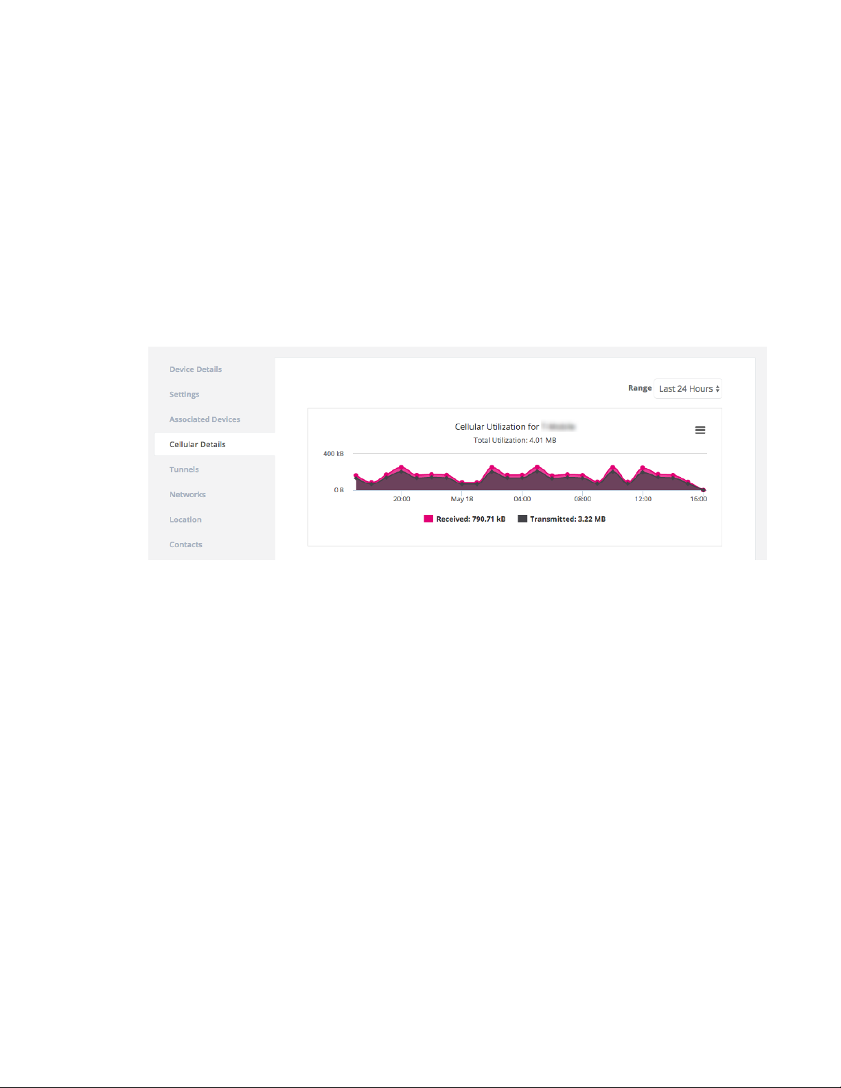
VPN Gateway devices VPN Gateway device details
n CID: The CID identifier of the modem's current connection.
n LAC: The LAC identifier of the modem's current connection.
n MCC: The mobile country code of the modem's current connection.
n MNC: The mobile network code of the modem's current connection.
n PLMN: The PLMN ID of the modem's current connection, which is a combination of the MCC and
MNC values.
VPN Gateway device Cellular Utilization chart
If a VPN Gateway's primary WAN connection is a cellular connection, and the device belongs to an
organization with the Enable Cellular Modem Data Collection option enabled (see the Device Settings
details in the Organizations section), a cellular utilization chart will be displayed on the Cellular Details
tab detailing the amount of cellular data used by the device.
VPN Gateway device Tunnels tab
The Tunnel tab lists details for the VPN tunnel established by the gateway device. If a Gateway device
has multiple tunnels active, there will be multiple tunnel tabs, each one corresponding to one of the
Gateway device's tunnels.
n Name: The name of the tunnel, as specified in the Service Manager profile.
n Connection ID: The unique identifier for the current tunnel connection.
n Connection Type: The type of network connection the tunnel is established over.
n Account: The account that the tunnel settings are registered under.
n User ID: The ATTUID that the tunnel settings are registered under
n Duration: The total time the current tunnel has been established as of when this page was
loaded.
n Mode: Indicates if the user can control the tunnel.
n Endpoint Type: The authentication server that will be used by the tunnel endpoint.
n Endpoint IP: The IP address of the tunnel endpoint.
n WAN Connection: The type of network configuration of the current WAN connection (WAN1,
WAN2, etc.)
n AGNS Managed: The service the tunnel is authenticated for.
Digi aView User Guide
75
Page 76

VPN Gateway devices VPN Gateway device details
n Auth Server: The server where the tunnel details are configured.
n Auth Protocol: The authentication protocol for the tunnel.
n Initiator: Indicates how the tunnel was initiated.
n Last Updated: The last time aView received an update concerning this tunnel.
VPN Gateway device Location tab
The location details for a VPN Gateway device are provided through the AT&T Service Manager profile
of the device. As such, location details are displayed as read-only for VPN Gateway devices. If you want
to set the location of a VPN Gateway device, they can do so through the Service Manager profile for
the VPN Gateway. In the profile, users can specify address details for the location, which aView will
then use to look up location coordinates for the device, or users can specify the latitude and longitude
coordinates manually in the Service Manager profile.
VPN Gateway device Intelliflow tab
The Intelliflow tab displays metrics gathered from the summarized netflows sent from the VPN
Gateway device to the aView netflow collector. For these netflows to be sent, the VPN Gateway’s
Service Manager profile must:
n Have the ARMT Netflow flag enabled.
n Use version 10 of netflow.
n Send its netflows to the aView netflow collector.
n Add a firewall rule to the VPN Gateway device’s policy list to allow netflow packets to pass out
through the device's maintenance tunnel to aView.
The metrics displayed on the Intelliflow tab detail the top 10 sources and destinations.
n Source: A source is an endpoint that clients request data from.
n Destintation: A client connected to the VPN Gateway devices’s LAN ports, or the VPN Gateway
device itself.
The source/destination labeling is used, because most network traffic is clients downloading traffic
from the Internet. If a customer’s VPN Gateway traffic is instead mostly uploading data, the
source/destination labels will be reversed, meaning the clients connected to the VPN Gateway will be
the source, and the destination will be the endpoints the clients are uploading data to.
Note Only IPv4 traffic is captured by the VPN Gateway and sent as summarized netflows to aView.
VPN Gateway Connectivity Tests tab
This tab lists the 10 most recent backup connectivity tests reported by the VPN Gateway device,
including:
n Result: whether the test passed or failed
n Reason: the error code (if applicable)
n Category: the category of the failed test (if applicable)
n Source: whether the test was manually triggered or automated
n Date: when the test was executed
Digi aView User Guide
76
Page 77

VPN Gateway devices VPN Gateway Remote commands
VPN Gateway IDS tab
This tab lists a count of IDS (intrusion detection) alerts detected by the VPN Gateway. The alerts are
broken down by IDS type and displayed on a table, showing details for each type of alert and how
many of each alert type was received.
The alerts are sent from the VPN Gateway to a Kafka REST API on ARMT. The VPN Gateway must be
running firmware version 6.5.0 or higher to send these alerts. The chart on the tab lists a total number
of alerts received per day (if any) over the past 30 days.
VPN Gateway Remote commands
Remote commands are sent to a VPN Gateway device through its management tunnel. If the Gateway
device's management tunnel to the aView site is disconnected, then you will not be able to send
remote commands to the Gateway device. The available remote commands that can be sent to
gateway devices are listed below. Any responses from sending one of these remote commands to a
Gateway device will be listed as an event in aView.
Firmware version 6.1.8 or newer
n Arping: Send an network ARPing to a specified IP address.
n Check Status: Perform an immediate SNMP probe of the gateway. device.
n Firmware: either check if a firmware update is available, or tell the Gateway device to upgrade
its firmware. The specified firmware version is based on the firmware URL defined in the
gateway's AT&T Service Manager profile. There is also an option to revert the device to the
rollback firmware version.
n Ping: ping a specified IP address.
n Profile Query: Send the command to perform a partial or full configuration update from the
device's AT&T Service Manager profile.
n Reboot: Send the command to reboot the Gateway device.
n Tracepath: trace the path to a specified network IP address, discovering MTU along this path
n Traceroute: trace the network path to a specified IP address.
n Wan Toggle: enable or disable a WAN interface on the Gateway device for a specified amount
of time. The Gateway device must be on firmware version 6.5.0 or higher to accept this
command.
n Backup WAN Test: manually run a backup connectivity test on the secondary WAN connection.
The Gateway device must be on firmware version 6.5.0 or higher to accept this command.
n Tunnels: provides the ability to check the status of all configured outbound tunnels of a
Gateway device, including bring a tunnel up/down, bounce a tunnel, or checking a tunnel's
status. The name and index of the desired outbound tunnel must be specified to perform these
commands.
Firmware versions older than 6.1.8
n Check Device Status: Perform an immediate SNMP probe of the gateway device.
n Check Configuration: Send the command to perform a partial or full update depending on the
Digi aView User Guide
77
Page 78

VPN Gateway devices VPN Gateway configuration requirements for aView
configuration option specified in the gateway device's AT&T Service Manager profile.
n Reboot Device: Send the command to reboot the Gateway device.
VPN Gateway configuration requirements for aView
aView utilizes a management tunnel to communicate with the gateway device. The management
tunnel must be configured correctly in order for aView to be able to probe and send commands to the
Gateway device. Contact your AT&T Service Manager specialist if assistance is needed configuring the
management tunnel of the Gateway device.
In addition to the management tunnel, the Gateway device must be configured to send its SNMP
Informs to the aView server. Several of the notifications sent by aView are based on the SNMP informs
sent by the Gateway device. Contact your AT&T Service Manager specialist if assistance is needed
configuring the SNMP Inform options of the Gateway device.
Digi aView User Guide
78
Page 79

Remote Manager devices
About Remote Manager devices 80
Remote Manager device details 80
Remote Manager device remote commands 84
Remote Manager configuration requirements for aView 85
Digi aView User Guide
79
Page 80
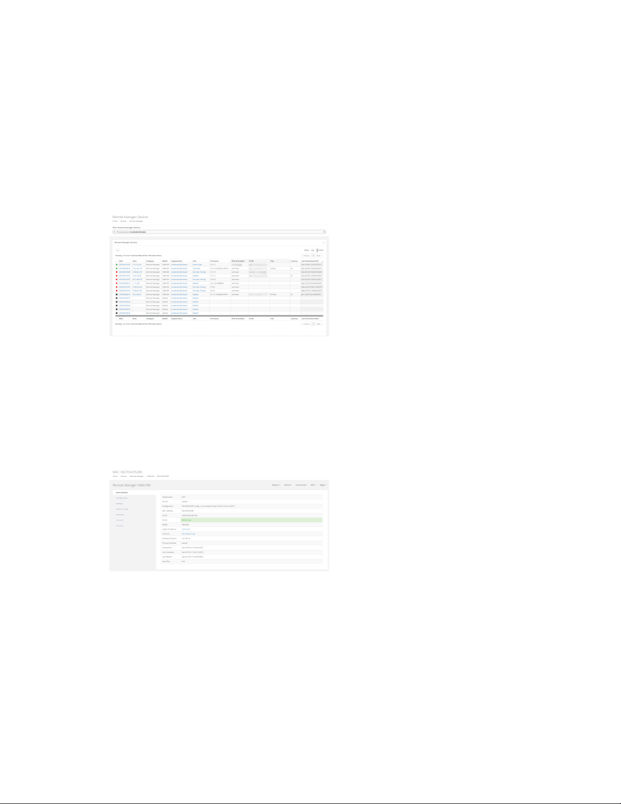
Remote Manager devices About Remote Manager devices
About Remote Manager devices
Remote Manager devices refer to the Digi Remote Manager line of products. Supported models are
listed below. A user can find a list of all the Remote Manager devices they have access to by clicking on
the Devices tab in the navigation bar, and then select the Remote Manager link from the dropdown.
n 5300-RM
n 5400-RM
n 5401-RM
n ConnectIT4
Remote Manager devices are listed in tabular form. The majority of the details are applicable to all
device categories. See Device details page for details on those table entries.
The table entries specific to Remote Manager devices are listed below.
n Phone Number: The phone number of the current cellular connection.
n ICCID: The number used to identify the SIM card used by the device.
Remote Manager device details
The majority of details provided on the Remote Manager device details page are applicable to all
categories of devices. See Device details page for details on those table entries.
The device details specific to Remote Manager devices are:
n Management IP: The IP address of the Remote Manager device's aView IPSec tunnel. If this IP
does not match the aView tunnel IP address listed in the local web UI of the Remote Manager
device, a user with the ability to modify devices will be given an option to edit the Management
IP address.
n Uplink IP Address: The IP address of the current WAN network connection of the Remote
Digi aView User Guide
80
Page 81

Remote Manager devices Remote Manager device details
Manager device.
n Primary Interface: The currently used WAN connection interface.
Remote Manager Configuration tab
Remote Manager devices are configured through the aView site. See Create a new Remote Manager
device configuration profile for details.
Remote Manager device Settings tab
The majority of details provided on the Remote Manager Settings tab are applicable to all categories
of devices. See Settings tab for details on those table entries.
The device details specific to Remote Manager devices are:
n Data Plan: The data plan assigned to the device. If the user has the ability to change the data
plan, a drop-down will be displayed and lists the available data plans for the organization the
device belongs to. Once a data plan is associated with the device, any cellular data used by the
device will be tracked in the data plan, which can be viewed and managed by clicking the Edit
button for an Organization (see Organizations). You also have the option of creating a new data
plan if desired.
Remote Manager Associated devices tab
This tab lists any devices that the Remote Manager device has associated with, indicating that they
are connected to each other. The tab will include the following details about the associated device.
n Device ID: The identifying MAC address for the associated device.
n Model: If the associated device is a type of device supported by ARMT, this entry will display the
type of device ARMT knows it as. If the device is not supported by ARMT, the category will be
listed with a dash ( - ).
n Interface: The physical interface of the Remote Manager device the associated device is
connected to.
n Type: How the associated device is connected to the Remote Manager device. For example, a
type listed as LAN indicates that the associated device is connected to one of the Remote
Manager device's LAN Ethernet ports.
n IP Address: The IP address of the associated device.
n Connected: Indicates when the device association was made and how long the associated
device has been connected to the Remote Manager device.
Remote Manager Cellular Details tab
The Cellular Details tab lists details for the Remote Manager modem. The name of the cellular
modem is listed in the title bar of the Cellular Details tab. If a Remote Manager device has multiple
modems, there will be multiple modem panels, each one corresponding to one of the cellular device's
modems. A modem entry can be removed by clicking the red trash icon at the top-right of the specific
tab.
n Carrier: The cellular provider of the modem.
n SKU: The stock keeping unit of the modem.
Digi aView User Guide
81
Page 82

Remote Manager devices Remote Manager device details
n Signal Strength: The current RSSI signal strength value, measured in dBm, and percentage of
the modem.
n Signal Bars: The current signal bars, based on the signal strength.
n Speed Test: The five most recent (if any) speed tests performed on the device. Speed tests are
generated by sending a Speed Test command to the device.
Note In order to minimize the speed test's impact on cellular data consumption, the results
are an estimation of the available throughput of the device, and may not represent the full
network speed available.
n Phone Number: The phone number of the modem.
n RSSI: The Received Signal Strength Indicator (RSSI) of the modem. RSSI provides information
about total received wide-band power, including signal interference and thermal noise.
n RSRP: An LTE-specific value, representing the Reference Signal Received Power of the modem.
RSRP is the average power of resource elements that carry cellular specific reference signals
over the entire bandwidth.
n RSRQ: An LTE-specific value, representing the Reference Signal Receive Quality (RSRQ) of the
modem. RSRQ is a combination of RSSI and RSRP and indicates the quality of the received
reference signal.
n SiNR: The signal-to-interference-plus-noise ratio of the modem.
n SNR: The signal-to-noise ratio of the modem.
n IMEI: The IMEI value of the modem.
n ESN: The ESN value of the modem. Note that the ESN value only applies to CDMA cellular
networks.
n ICCID: The ICCID value of the SIM card used by the modem.
n IMSI: The IMSI value of the modem.
n Revision: The hardware version of the modem.
n APN: The APN that the modem is currently connected with. Note that not all modems require
an APN.
n ECIO: The signal-to-noise ratio of the modem. The lower the Ec/Io value, the greater the noise.
n CNTI: The technology type that the modem is currently connected to.
n Band: The frequency or type of cellular band the modem is currently connected to.
n CID: The CID identifier of the modem's current connection.
n LAC: The LAC identifier of the modem's current connection.
n MCC: The mobile country code of the modem's current connection.
n MNC: The mobile network code of the modem's current connection.
n PLMN: The PLMN ID of the modem's current connection, which is a combination of the MCC and
MNC values.
n USB Speed: The speed of the USB port(s) on the Remote Manager device, measured in Mbps.
480 indicates USB 2.0 High Speed and 12 indicates USB 2.0 Full Speed.
Cellular utilization chart
If the device supports a cellular modem, a cellular utilization chart will be displayed. The chart shows
the amount of cellular data used by the device. The initial timespan will display the data usage for the
Digi aView User Guide
82
Page 83
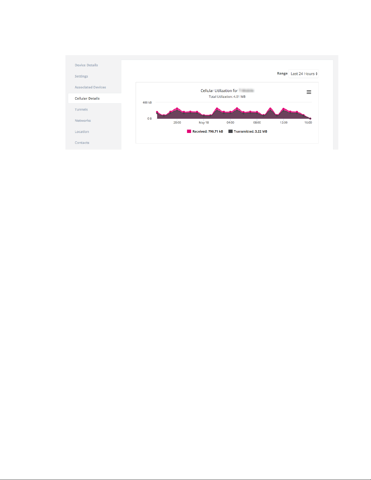
Remote Manager devices Remote Manager device details
past 24 hours. You can select different timespans from the Range drop-down.
Remote Manager Tunnels tab
The Tunnel tab lists status for any IPSec tunnels established by the Remote Manager device. Each
row of the tab indicates a unique IPSec tunnel of the device.
n Name: The name of the IPSec tunnel, as specified in the configuration of the Remote Manager
device.
n Status: Indicates whether or not the Remote Manager device has established the IPSec tunnel.
n Last Updated: The last time aView received an update concerning this tunnel.
n IpLocal: The tunnel IP address assigned to the Remote Manager device.
n IpRemote: The IP address of the server that the Remote Manager device built a tunnel to.
n NetLocal: The network settings on the Remote Manager device for the tunnel.
n NetRemote: The network settings on the server for the tunnel.
Remote Manager Network tab
The Network tab lists details for network interfaces that belong to the Remote Manager device. If a
Remote Manager device has multiple networks, there will be multiple network tabs, each one
corresponding to one of the device's networks.
n Connection Type: the type of network connection for the interface.
n Metric: The priority level of the network interface. The lower the number, the higher in priority
the interface.
n Priority: Indicates if the network connection is the current primary or alternate connection.
n IP Ranges: The IP addressing for the network.
n MTU: The MTU size of the network interface.
n Gateway IP: The default route (gateway IP) of the network interface.
n Bytes Received: The total amount of data received, measured in bytes, on the network
interface since the Remote Manager device has been online (resets on reboot).
n Bytes Transmitted: The total amount of data transmitted, measured in bytes, on the network
interface since the Remote Manager device has been online (resets on reboot).
Digi aView User Guide
83
Page 84

Remote Manager devices Remote Manager device remote commands
n Ethernet Speed: If the network type is an Ethernet interface, then this indicates the speed of
the Ethernet port.
n Ethernet Status: If the network type is an Ethernet interface, then this indicates the status of
the physical connection on the Ethernet port.
Remote Manager device remote commands
Remote commands are sent to a Remote Manager device through an IPSEC tunnel the device
establishes to the Accelerated remote control server, or through the upstream IP address of the
device if no tunnel IP is available. All Remote Manager devices by default establish an IPSec tunnel to
remote.accns.com. See aView tunnel alternatives for information about additional IPSec tunnel
endpoints.
The tunnel IP address for the Remote Manager device is stored in aView as the Management IP on the
Device Details tab. If the Management IP is not known, then aView will use the IP address listed in
the Uplink IP Address field on the Device Details tab for sending remote commands.
When you send a remote command to a device, aView utilizes a DNS service running on the remote
control server to verify what tunnel IP address is associated with the device. If the DNS service
responds with a valid IP address, aView will send the remote command to that IP address, otherwise
it will use the known Management IP or the Uplink IP Address if the Management IP is unknown. If the
IP address returned by the DNS service differs than the Management IP listed for the device, aView
will update the Management IP after successfully sending the remote command to the device.
Before sending the remote command to the Remote Manager device, aView will prompt the user to
provide the device-level username and password to authenticate with the device. If you do not know
the username or password for the device, navigate to the Configuration tab of the device in aView
and select Authentication > Users. Select a user name to change the password. You can also change
the password locally on the device by following the instructions in the device's user manual. For
example, to view instructions for the EX15, visit
https://www.digi.com/resources/documentation/digidocs/90002344/default.htm#os/user-localchange-pswd-t.htm.
Once the username and password are provided for the device, aView will then perform a HTTP
request to the device to validate that the correct device is at the given IP address. If the correct
device is reached and authenticated, the remote command will be sent.
The available remote commands that can be sent to Remote Manager devices are:
n Check status: The Remote Manager device will immediately send its current status.
n Check signal strength: The Remote Manager device will send its signal strength and network
info once every 10 seconds for the next 15 minutes.
n Perform Speed Test: The Remote Manager device will perform a speed test and send the
Upload/Download results.
Note In order to minimize the speed test's impact on cellular data consumption, the results
are an estimation of the available throughput of the device, and may not represent the full
network speed available.
n ARPing Attached Device: The Remote Manager device will attempt to ARPing the client device
attached to its Ethernet port.
n Send Wake-on-LAN to Attached Device: The Remote Manager device will send a wake-on-
LAN packet to the client device attached to its Ethernet port.
Digi aView User Guide
84
Page 85

Remote Manager devices Remote Manager configuration requirements for aView
n Check Configuration: The Remote Manager device will immediately pull its configuration and
reboot to apply any new settings.
n Update Modem Firmware: The Remote Manager device will query the Digi firmware server. If
a new version of firmware is found for the active firmware used on the embedded modem in
the Remote Manager device, it will download the new firmware and update the embedded
modem. Note the Remote Manager device must be running firmware version 17.8.128 or
higher to process this command.
n Reboot: Reboot the Remote Manager device.
Remote Manager device emergency SMS commands
As an alternative to the Remote commands, you can also send commands via SMS messaging to a
Remote Manager device. The SIM card used by the Remote Manager device must have SMS enabled,
or you will not be able to send SMS commands.
The available SMS commands that can be sent are:
n Set Configuration: A pop-up window appears where a user can enter in a configuration option
or set of options to apply to the Remote Manager device. Multiple config options must be
separated by a comma. For example, if a user wants to set the APN of a Remote Manager
device to managedvpn, they would enter "modem_apn=managedvpn".
n Configuration Reset: Restore default configuration on the Remote Manager device and
reboot.
n Firmware Reset: Restore to the backup firmware image on the Remote Manager device, and
reboot.
n Factory Reset: Restore default configuration on the Remote Manager device, restore to the
backup firmware image, and reboot.
n Remote Control: Tell the Remote Manager device to bring up its remote control tunnel (useful
if on low data plan, so the remote control tunnel is not always up using data).
n Reboot: Reboot the Remote Manager device.
Remote Manager configuration requirements for aView
In order for the aView site to monitor a Remote Manager device, it must send its syslogs to the aView
syslog server IP address, the domain of which is logs.accns.com.
For a Remote Manager device to get its configuration from the aView site, it must be set to pull its
configuration from the aView configuration server configuration.accns.com. The device must also be
able to sync its date and time with an NTP server; the default is time.accns.com.
In the device configuration, ensure the following options are set in Service > Web administration:
n Enable is selected.
n Port is set to 443.
n Access control list -> Zones includes the IPSec zone.
This zone is included by default, but it's mentioned here for the user to verify that it is still
present, in case the device is running settings that deviate from the default configuration.
Digi aView User Guide
85
Page 86
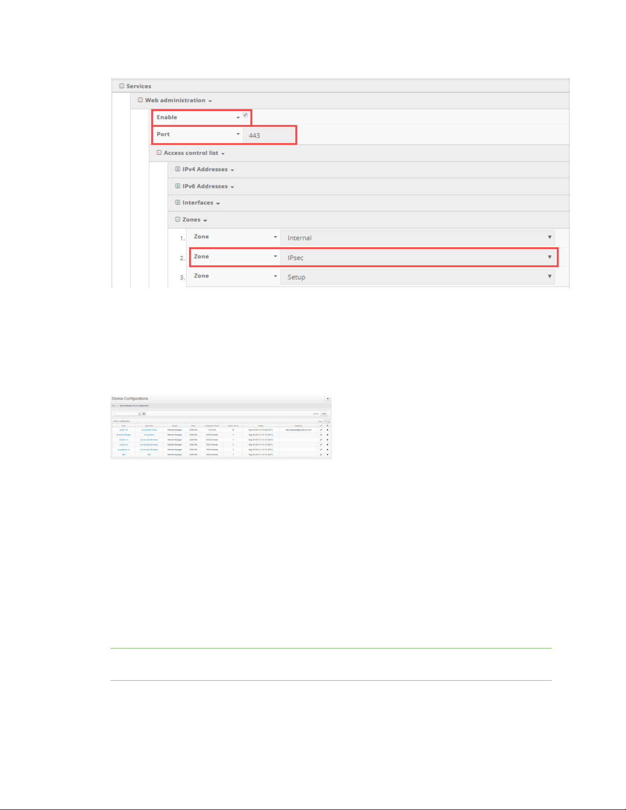
Remote Manager devices Remote Manager configuration requirements for aView
View Remote Manager configuration profiles
To view the current list of group configuration profiles a user has access to:
1. Click on the Configurations button in the navigation panel.
2. Select Remote Manager in the drop-down.
Create a new Remote Manager device configuration profile
To create a new group configuration profile:
1. Click on the Configurations button in the navigation panel.
2. Select Remote Manager in the drop-down.
3. Click the plus icon located at the top right of the window.
4. Select the firmware version. The appropriate configuration schema will automatically load.
5. Set any desired settings in the presented configuration schema. Hovering your mouse over the
name for a configuration option will display a pop-up providing help details about that option,
including any default values. Once all the desired configuration options have been specified,
click Create.
Note If the desired firmware is not listed, it must be uploaded onto the firmware management
service, which is hosted at distro.accns.com.
Digi aView User Guide
86
Page 87
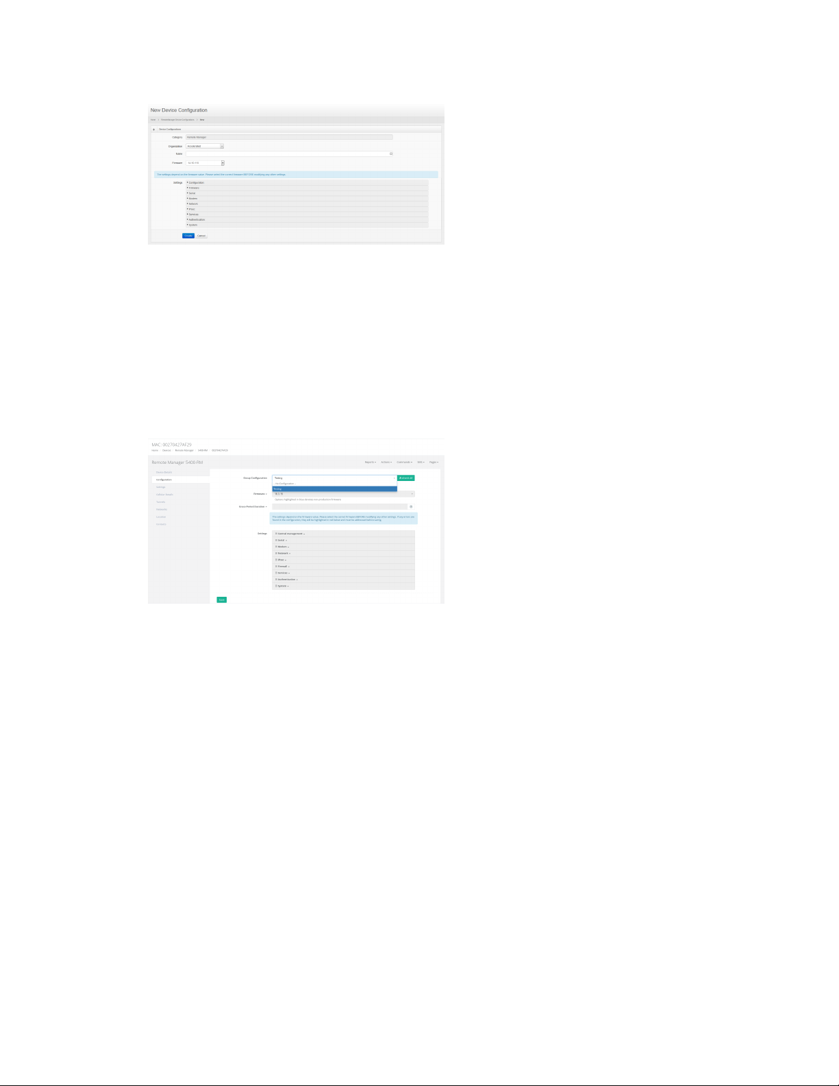
Remote Manager devices Remote Manager configuration requirements for aView
Apply a Remote Manager configuration profile
To apply a group configuration profile to a Remote Manager device:
1. Go to the device details page for the specific device. This can be done by searching for the
device's MAC address in the search bar, then clicking on the MAC address of the correct device
in the results.
2. Once on the details page, click on the Configuration tab, select the new configuration profile
from the Group Configuration drop-down, and click the Save button.
Individual device configuration settings
In addition to applying a group configuration profile to a device, authorized users will also have the
option of setting configuration options to apply only to an individual device. These individual device
configuration options are listed in the Configuration tab, below the Group Configuration option.
When a new group configuration is selected for a device, a list of inherited configuration settings from
that group configuration profile will be displayed. Authorized users can then click on any setting and
select the Override option to change the selected configuration option. It is important to note that
any configuration option overridden in this way will only apply to that individual device. Any other
devices that are linked to the same group configuration will only receive configuration settings from
the group configuration profile, not any of the overridden settings from another individual device's
configuration.
n Inherit All: This button can be used to reset an individual device's configuration back to the
group configuration profile's settings. Any configuration options previously overridden in the
individual device configuration will be undone and reset back to the settings inside the group
configuration.
Digi aView User Guide
87
Page 88

Remote Manager devices Remote Manager configuration requirements for aView
Delete a Remote Manager configuration profile
Configuration profiles can be deleted by clicking on the Delete icon for the appropriate profile on the
Remote Manager Configurations page. A confirmation pop-up will ask the user to confirm that they
wish to delete the configuration profile. If there are any devices linked to the configuration profile that
is being deleted, the profile will not be deleted. The user must first unlink the configuration profile
from the device and then they can remove the profile.
Digi aView User Guide
88
Page 89

WiFi devices
About WiFi devices 90
WiFi device details 90
Configuration 91
WiFi configuration requirements for aView 91
Digi aView User Guide
89
Page 90
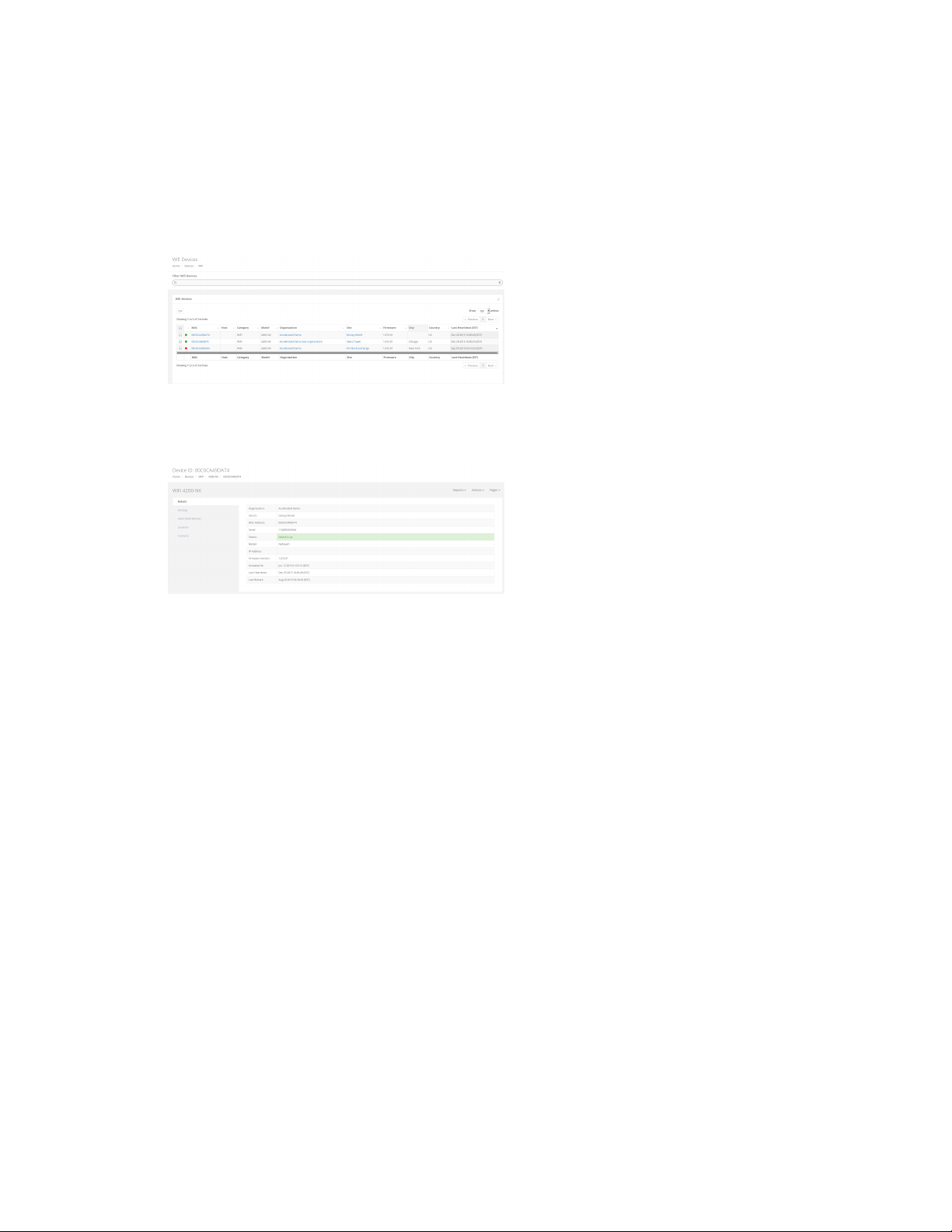
WiFi devices About WiFi devices
About WiFi devices
WiFi devices refer to the Digi WiFi Extender line of products. Supported models are listed below. A user
can find a list of all the WiFi devices they have access to by clicking on the Devices tab in the navigation
bar, and then select the WiFi link from the drop-down.
n 4200-NX
WiFi device details
The majority of details provided on the WiFi device details page are applicable for all categories of
devices. See Device details page for details on those table entries.
The device details specific to WiFi devices are:
n IP Address: The WAN IP address of the WiFi device.
Associated devices tab
This tab lists any devices that the WiFi device has associated with, indicating that they are connected
to each other. The tab will include the following details about the associated device.
n Device ID: The identifying MAC address for the associated device.
n Model: If the associated device is a type of device supported by ARMT, this entry will display the
type of device ARMT knows it as. If the device is not supported by ARMT, the category will be
listed with a dash ( - ).
n Interface: The physical interface of the WiFi device the associated device is connected to.
n Type: How the associated device is connected to the WiFi device. For example, a type listed as
WAN indicates that the associated device is connected to one of the WiFi device's WAN
Ethernet ports.
n IP Address: The IP address of the associated device.
n Connected: Indicates when the device association was made and how long the associated
device has been connected to the WiFi device.
Digi aView User Guide
90
Page 91

WiFi devices Configuration
Rogue access points tab
The WiFi device can be configured to search for other wireless Access Points (APs). Any of these
nearby APs that also happen to be on the same LAN as the WiFi device will be flagged as a rogue AP.
This tab lists any rogue APs discovered by the WiFi device. The following details are included about
each rogue AP.
n MAC: The identifying MAC address of the rogue AP.
n SSID: The wireless SSID broadcasted by the rogue AP.
n IP: The IP address of the rogue AP.
Configuration
WiFi devices are configured through the AT&T Service Manager.
WiFi configuration requirements for aView
In order for the aView site to monitor a WiFi device, it must send its syslogs to the aView syslog server
IP address, the domain of which is logs.accns.com
Digi aView User Guide
91
Page 92

uCPE devices
About uCPE devices 93
uCPE device details 93
uCPE device remote commands 96
uCPE configuration requirements for aView 98
Digi aView User Guide
92
Page 93
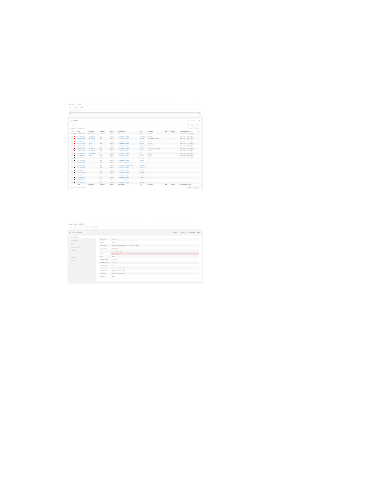
uCPE devices About uCPE devices
About uCPE devices
uCPE devices refer to the Digi uCPE line of products. Supported models are listed below. A user can
find a list of all the uCPE devices they have access to by clicking on the Devices tab in the navigation
bar, and then select the uCPE link from the dropdown.
n HERO 9400-UA
uCPE device details
The majority of details provided on the uCPE device details page are applicable to all categories of
devices. For details on those table entries, refer to the Devices section of this guide. The device details
specific to uCPE devices are listed below.
n Management IP: The IP address of the uCPE device's aView IPSec tunnel. If this IP does not
match the aView tunnel IP address listed in the local web UI of the uCPE device, a user with
the ability to modify devices will be given an option to edit the Management IP address.
n Uplink IP Address: The IP address of the current WAN network connection of the uCPE device.
n Primary Interface: The currently used WAN connection interface.
Configuration tab
uCPE devices are configured through the aView site. See Create a new uCPE device configuration
profile for details.
uCPE device Settings tab
The majority of details provided on the uCPE Settings tab are applicable to all categories of devices.
See Settings tab for details on those table entries.
The device details specific to uCPE devices are:
Digi aView User Guide
93
Page 94

uCPE devices uCPE device details
n Data Plan: The data plan assigned to the device. If the user has the ability to change the data
plan, a drop-down will be displayed and lists the available data plans for the organization the
device belongs to. Once a data plan is associated with the device, any cellular data used by the
device will be tracked in the data plan, which can be viewed and managed by clicking the Edit
button for an Organization (see Organizations). You also have the option of creating a new data
plan if desired.
Associated devices
This tab lists any devices that the uCPE device has associated with, indicating that they are connected
to each other. The tab will include the following details about the associated device.
n Device ID: The identifying MAC address for the associated device.
n Model: If the associated device is a type of device supported by ARMT, this entry will display the
type of device ARMT knows it as. If the device is not supported by ARMT, the category will be
listed with a dash ( - ).
n Interface: The physical interface of the uCPE device the associated device is connected to.
n Type: How the associated device is connected to the uCPE device. For example, a type listed as
LAN indicates that the associated device is connected to one of the uCPE device's LAN Ethernet
ports.
n IP Address: The IP address of the associated device.
n Connected: Indicates when the device association was made and how long the associated
device has been connected to the uCPE device.
uCPE device Cellular Details tab
The Cellular Details tab lists details for the uCPE modem. The name of the cellular modem is listed in
the title bar of the Cellular Details tab. If a uCPE device has multiple modems, there will be multiple
modem panels, each one corresponding to one of the uCPE device's modems. A modem entry can be
removed by clicking the red trash icon at the top-right of the specific tab.
n Carrier: The cellular provider of the modem.
n SKU: The stock keeping unit of the modem.
n Signal Strength: The current RSSI signal strength value, measured in dBm, and percentage of
the modem.
n Signal Bars: The current signal bars, based on the signal strength.
n Speed Test: The five most recent (if any) speed tests performed on the device. Speed tests are
generated by sending a Speed Test command to the device.
Note In order to minimize the speed test's impact on cellular data consumption, the results
are an estimation of the available throughput of the device, and may not represent the full
network speed available.
n Phone Number: The phone number of the modem.
n RSSI: The Received Signal Strength Indicator (RSSI) of the modem. RSSI provides information
about total received wide-band power, including signal interference and thermal noise.
Digi aView User Guide
94
Page 95
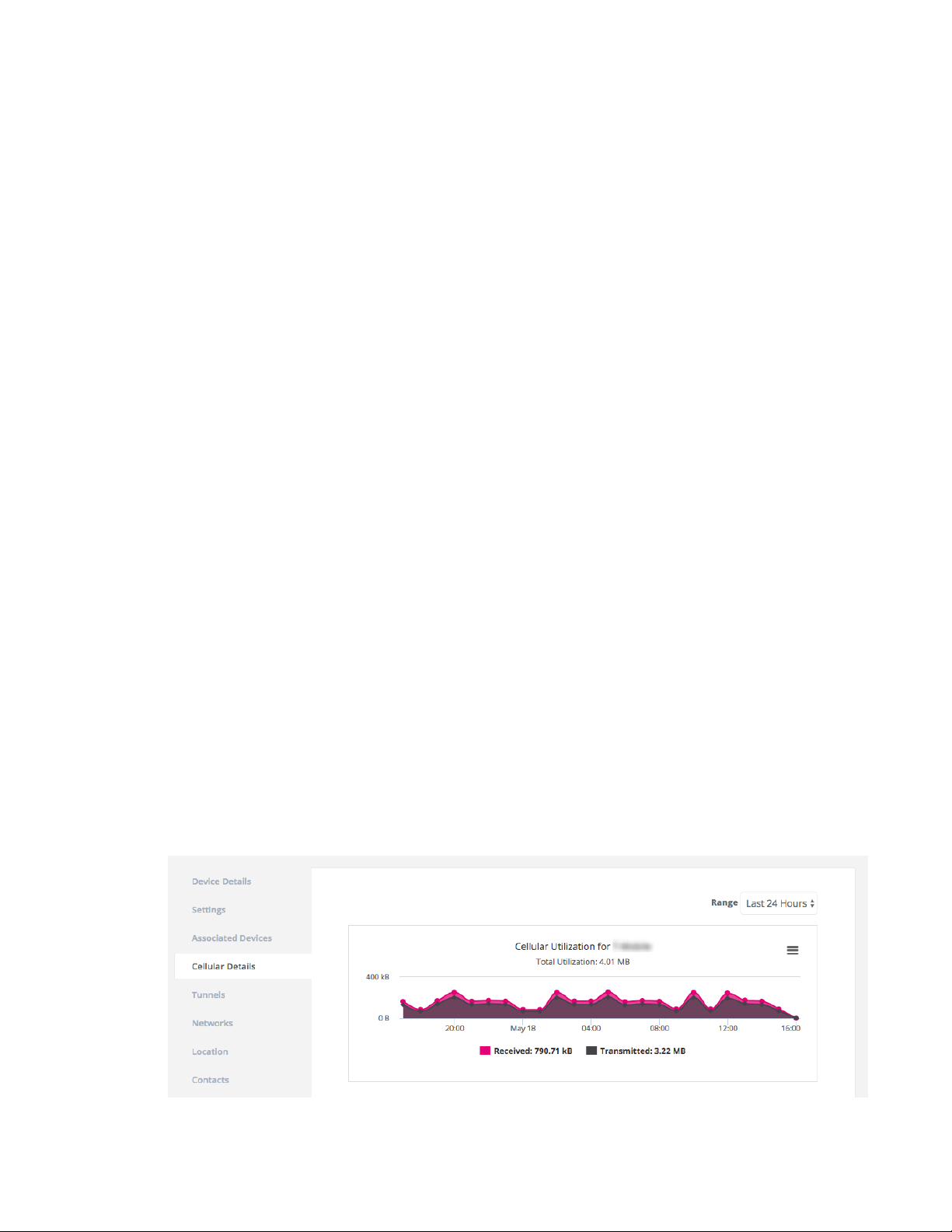
uCPE devices uCPE device details
n RSRP: An LTE-specific value, representing the Reference Signal Received Power of the modem.
RSRP is the average power of resource elements that carry cellular specific reference signals
over the entire bandwidth.
n RSRQ: An LTE-specific value, representing the Reference Signal Receive Quality (RSRQ) of the
modem. RSRQ is a combination of RSSI and RSRP and indicates the quality of the received
reference signal.
n SiNR: The signal-to-interference-plus-noise ratio of the modem.
n SNR: The signal-to-noise ratio of the modem.
n IMEI: The IMEI value of the modem.
n ESN: The ESN value of the modem. Note that the ESN value only applies to CDMA cellular
networks.
n ICCID: The ICCID value of the SIM card used by the modem.
n IMSI: The IMSI value of the modem.
n Revision: The hardware version of the modem.
n APN: The APN that the modem is currently connected with. Note that not all modems require
an APN.
n ECIO: The signal-to-noise ratio of the modem. The lower the Ec/Io value, the greater the noise.
n CNTI: The technology type that the modem is currently connected to.
n Band: The frequency or type of cellular band the modem is currently connected to.
n CID: The CID identifier of the modem's current connection.
n LAC: The LAC identifier of the modem's current connection.
n MCC: The mobile country code of the modem's current connection.
n MNC: The mobile network code of the modem's current connection.
n PLMN: The PLMN ID of the modem's current connection, which is a combination of the MCC and
MNC values.
n USB Speed: The speed of the USB port(s) on the uCPE device, measured in Mbps. 480 indicates
USB 2.0 High Speed and 12 indicates USB 2.0 Full Speed.
Cellular utilization chart
If the device supports a cellular modem, a cellular utilization chart will be displayed. The chart shows
the amount of cellular data used by the device. The initial timespan will display the data usage for the
past 24 hours. You can select different timespans from the Range drop-down.
Digi aView User Guide
95
Page 96

uCPE devices uCPE device remote commands
uCPE device Tunnels tab
The Tunnels tab lists status for any IPSec tunnels established by the uCPE device. Each row of the tab
indicates a unique IPSec tunnel of the device.
n Name: The name of the IPSec tunnel, as specified in the configuration of the uCPE device.
n Status: Indicates whether or not the uCPE device has established the IPSec tunnel.
n IpLocal: The tunnel IP address assigned to the uCPE device.
n IpRemote: The IP address of the server that the uCPE device built a tunnel to.
n NetLocal: The network settings on the uCPE device for the tunnel.
n NetRemote: The network settings on the server for the tunnel.
uCPE device Network tab
The Network tab lists details for network interfaces that belong to the uCPE device. If a uCPE device
has multiple networks, there will be multiple network tabs, each one corresponding to one of the
device's networks.
n Connection Type: the type of network connection for the interface.
n Metric: The priority level of the network interface. The lower the number, the higher in priority
the interface.
n Priority: Indicates if the network connection is the current primary or alternate connection.
n IP Ranges: The IP addressing for the network.
n MTU: The MTU size of the network interface.
n Gateway IP: The default route (gateway IP) of the network interface.
n Bytes Received: The total amount of data received, measured in bytes, on the network
interface since the uCPE device has been online (resets on reboot).
n Bytes Transmitted: The total amount of data transmitted, measured in bytes, on the network
interface since the uCPE device has been online (resets on reboot).
n Ethernet Speed: If the network type is an Ethernet interface, then this indicates the speed of
the Ethernet port.
n Ethernet Status: If the network type is an Ethernet interface, then this indicates the status of
the physical connection on the Ethernet port.
uCPE device remote commands
Remote commands are sent to a uCPE device through an IPSEC tunnel the device establishes to the
Accelerated remote control server, or through the upstream IP address of the device if no tunnel IP is
available. All uCPE devices by default establish an IPSec tunnel to remote.accns.com. See aView tunnel
alternatives for information about additional IPSec tunnel endpoints.
The tunnel IP address for the uCPE device is stored in aView as the Management IP on the Device
Details tab. If the Management IP is not known, then aView will use the IP address listed in the
Uplink IP Address field on the Device Details tab for sending remote commands.
When you send a remote command to a device, aView utilizes a DNS service running on the remote
control server to verify what tunnel IP address is associated with the device. If the DNS service
responds with a valid IP address, aView will send the remote command to that IP address, otherwise
it will use the known Management IP or the Uplink IP Address if the Management IP is unknown. If the
Digi aView User Guide
96
Page 97

uCPE devices uCPE device remote commands
IP address returned by the DNS service differs than the Management IP listed for the device, aView
will update the Management IP after successfully sending the remote command to the device.
Before sending the remote command to the uCPE device, aView will prompt the user to provide the
device-level username and password to authenticate with the device. If you do not know the
username or password for the device, navigate to the Configuration tab of the device in aView and
select Authentication > Users. Select a user name to change the password. You can also change the
password locally on the device by following the instructions in the device's user manual. For example,
to view instructions for the EX15, visit
https://www.digi.com/resources/documentation/digidocs/90002344/default.htm#os/user-localchange-pswd-t.htm.
Once the username and password are provided for the device, aView will then perform a HTTP
request to the device to validate that the correct device is at the given IP address. If the correct
device is reached and authenticated, the remote command will be sent.
The available remote commands that can be sent to uCPE devices are:
n Check status: The uCPE device will immediately send its current status.
n Check signal strength: The uCPE device will send its signal strength and network info once
every 10 seconds for the next 15 minutes.
n Perform Speed Test: The uCPE device will perform a speed test and send the
Upload/Download results.
Note In order to minimize the speed test's impact on cellular data consumption, the results
are an estimation of the available throughput of the device, and may not represent the full
network speed available.
n ARPing Attached Device: The uCPE device will attempt to ARPing the client device attached
to its Ethernet port.
n Send Wake-on-LAN to Attached Device: The uCPE device will send a wake-on-LAN packet to
the client device attached to its Ethernet port.
n Check Configuration: The uCPE device will immediately pull its configuration and reboot to
apply any new settings.
n Update Modem Firmware: The uCPE device will query the Digi firmware server. If a new
version of firmware is found for the active firmware used on the embedded modem in the uCPE
device, it will download the new firmware and update the embedded modem. Note the uCPE
device must be running firmware version 17.8.128 or higher to process this command.
n Reboot: Reboot the uCPE device.
uCPE device emergency SMS commands
As an alternative to the Remote commands, you can also send commands via SMS messaging to a
uCPE device. The SIM card used by the uCPE device must have SMS enabled, or you will not be able to
send SMS commands.
The available SMS commands that can be sent are:
n Set Configuration: A pop-up window appears where a user can enter in a configuration option
or set of options to apply to the uCPE device. Multiple config options must be separated by a
comma. For example, if a user wants to set the APN of a uCPE device to managedvpn, they
would enter "modem_apn=managedvpn".
n Configuration Reset: Restore default configuration on the uCPE device and reboot.
Digi aView User Guide
97
Page 98
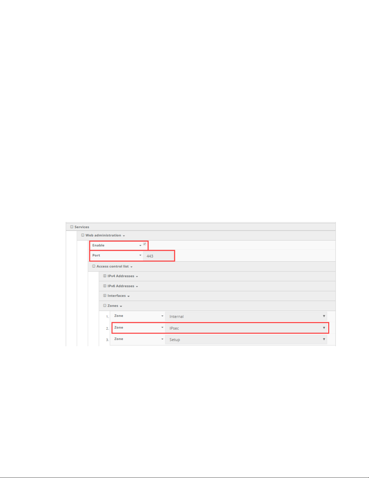
uCPE devices uCPE configuration requirements for aView
n Firmware Reset: Restore to the backup firmware image on the uCPE device, and reboot.
n Factory Reset: Restore default configuration on the uCPE device, restore to the backup
firmware image, and reboot.
n Remote Control: Tell the uCPE device to bring up its remote control tunnel (useful if on low
data plan, so the remote control tunnel is not always up using data).
n Reboot: Reboot the uCPE device.
uCPE configuration requirements for aView
In order for the aView site to monitor a uCPE device, it must send its syslogs to the aView syslog
server IP address, the domain of which is logs.accns.com.
For a uCPE device to get its configuration from the aView site, it must be set to pull its configuration
from the aView configuration server configuration.accns.com. The device must also be able to sync its
date and time with an NTP server; the default is time.accns.com.
In the device configuration, ensure the following options are set in Service > Web administration:
n Enable is selected.
n Port is set to 443.
n Access control list -> Zones includes the IPSec zone.
This zone is included by default, but it's mentioned here for the user to verify that it is still
present, in case the device is running settings that deviate from the default configuration.
View list of uCPE configuration profiles
To view the current list of group configuration profiles a user has access to:
1. Click on the Configurations button in the navigation panel.
2. Select uCPE in the drop-down.
Digi aView User Guide
98
Page 99
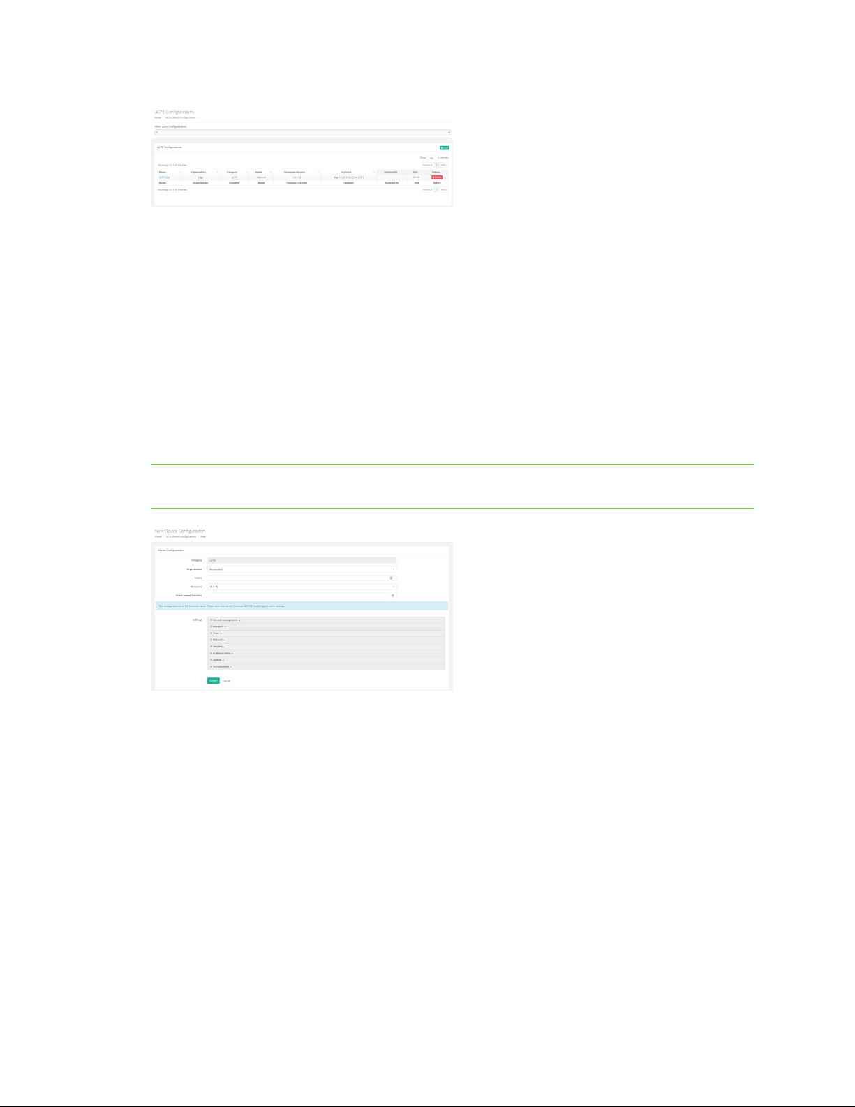
uCPE devices uCPE configuration requirements for aView
Create a new uCPE device configuration profile
To create a new group configuration profile:
1. Click on the Configurations button in the navigation panel.
2. Select uCPE in the drop-down.
3. Click the plus icon located at the top right of the window.
4. Select the firmware version. The appropriate configuration schema will automatically load.
5. Set any desired settings in the presented configuration schema. Hovering your mouse over the
name for a configuration option will display a pop-up providing help details about that option,
including any default values. Once all the desired configuration options have been specified,
click Create.
Note If the desired firmware is not listed, it must be uploaded onto the firmware management
service, which is hosted at distro.accns.com.
Apply a uCPE configuration profile
To apply a group configuration profile to a uCPE device:
1. Go to the device details page for the specific device. This can be done by searching for the
device's MAC address in the search bar, then clicking on the MAC address of the correct device
in the results.
2. Once on the details page, click on the Configuration tab, select the new configuration profile
from the Group Configuration drop-down, and click the Save button.
Digi aView User Guide
99
Page 100
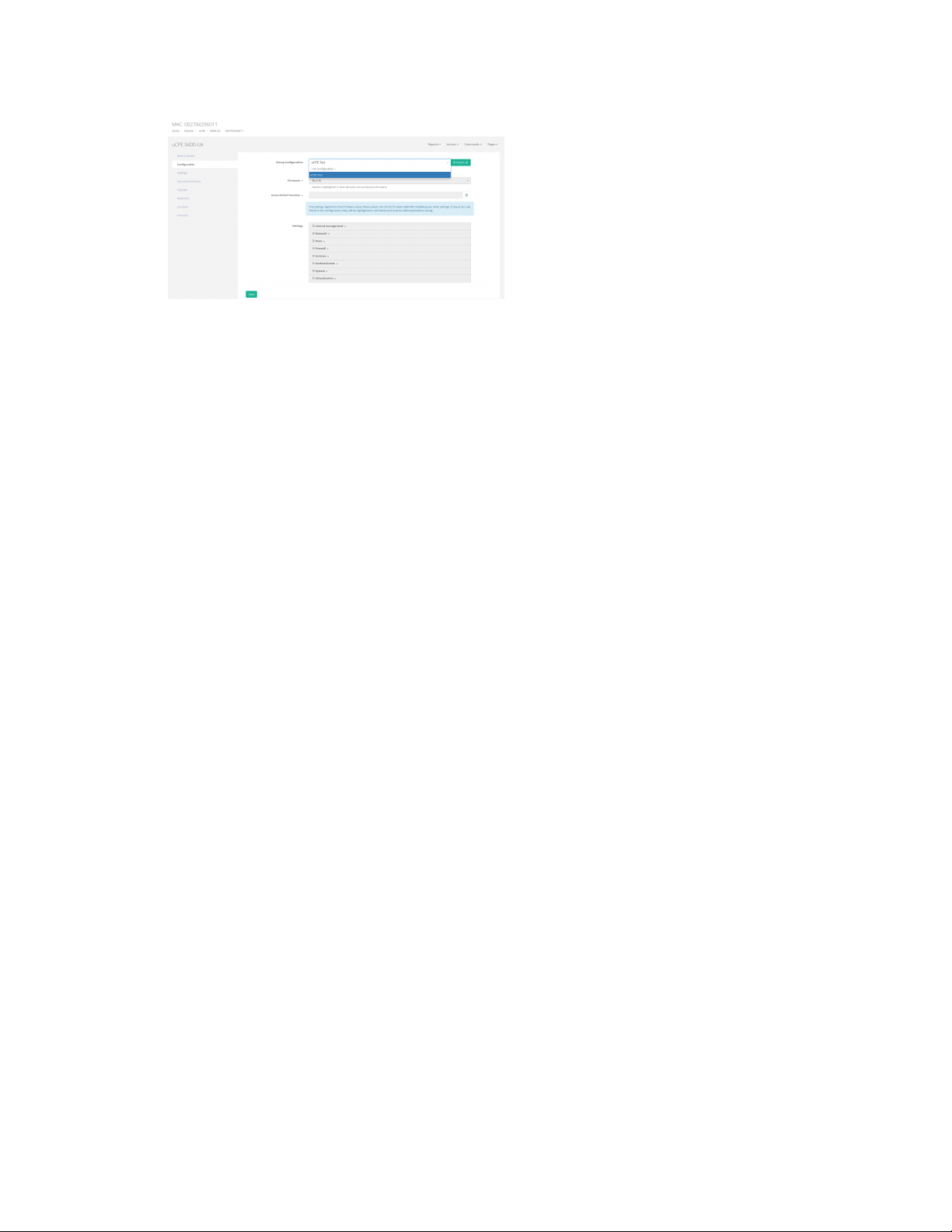
uCPE devices uCPE configuration requirements for aView
Individual uCPE device configuration settings
In addition to applying a group configuration profile to a device, authorized users will also have the
option of setting configuration options to apply only to an individual device. These individual device
configuration options are listed in the Configuration tab, below the Group Configuration option.
When a new group configuration is selected for a device, a list of inherited configuration settings from
that group configuration profile will be displayed. Authorized users can then click on any setting and
select the Override option to change the selected configuration option. It is important to note that
any configuration option overridden in this way will only apply to that individual device. Any other
devices that are linked to the same group configuration will only receive configuration settings from
the group configuration profile, not any of the overridden settings from another individual device's
configuration.
n Inherit All: This button can be used to reset an individual device's configuration back to the
group configuration profile's settings. Any configuration options previously overridden in the
individual device configuration will be undone and reset back to the settings inside the group
configuration.
Delete a uPCE configuration profile
Configuration profiles can be deleted by clicking on the X delete icon for the appropriate profile on the
uCPE Configurations page. A confirmation pop-up will ask the user to confirm that they wish to
delete the configuration profile. If there are any devices linked to the configuration profile that is
being deleted, the profile will not be deleted. The user must first unlink the configuration profile from
the device and then they can remove the profile.
Digi aView User Guide
100
 Loading...