

Page 1
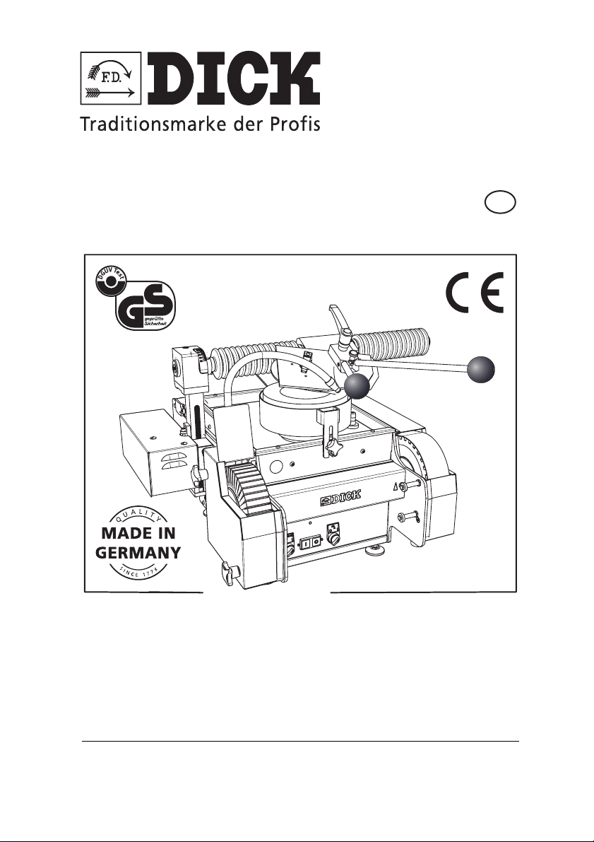
Operating Instructions (Translation)
GB
SM-200 TE
3~400 V - 50-60 Hz
Grinding and Honing Machine
Art. No. 98320005 with a universal grinding arm
Art. No. 98320000 with a radial grinding arm
Friedr. Dick GmbH & Co. KG · PO Box 1173 · 73777 Deizisau · GERMANY
Tel.: +49 (0)7153-817-0 · Fax: +49 (0)7153-817-218/-219 · Web: www.dick.de · E-mail: [email protected] ·
No. 9 8320 4252 Vers.2 / 11-2017
Page 2

Manufacturer and customer service address
Friedr. Dick GmbH & Co. KG
PO Box 1173
73777 Deizisau
GERMANY
Also visit the Friedr. Dick YouTube channel.
https://www.youtube.com/user/FriedrDick/videos
Videos show the operation of the Friedr. Dick machines.
Copyright
© 2016 Friedr. Dick GmbH & Co. KG.
These operating instructions are protected by copyright; all rights are reserved.
These operating instructions may not be reproduced or copied, either in full or
in part, without the prior consent of Friedr. Dick GmbH & Co. KG. Infringements
are subject to compensation claims and can result in criminal prosecution.
Page 3
1. User Information.............................................................................5
1.1 General................................................................................................. 5
1.2 Symbols and conventions .................................................................... 5
1.3 Symbols................................................................................................ 6
2. Delivery, Transport and Storage...................................................7
2.1 Delivery ................................................................................................ 7
2.2 Package contents................................................................................. 7
2.3 Unpacking ............................................................................................ 7
2.4 Transportation ...................................................................................... 8
2.5 Storage location ................................................................................... 9
3. Product Liability ...........................................................................10
4. Environmental Protection............................................................10
5. Safety.............................................................................................11
5.1 Meaning of the warnings .................................................................... 11
5.2 Intended use....................................................................................... 11
5.3 General safety instructions................................................................. 12
5.5 Signage .............................................................................................. 17
5.6 Covers................................................................................................ 18
6. Design and Function....................................................................19
6.1 Technical data.................................................................................... 19
6.2 Overview ............................................................................................ 21
6.3 Design and Function .......................................................................... 22
6.4 Covers................................................................................................ 26
7. Putting the Machine into Operation............................................27
7.1 Installing the machine......................................................................... 27
7.2 Mounting the grinding arm.................................................................. 28
7.3 Removing the dressing tool................................................................ 29
7.4 Setting up the cooling water unit ........................................................ 29
7.5 Filling the cooling water unit ............................................................... 29
7.6 Electrical connection .......................................................................... 30
7.7 Performing test runs ........................................................................... 30
8. Setting up the Machine................................................................33
8.1 Switching on the grinding and honing machine.................................. 33
8.2 Switching off the grinding and honing machine.................................. 34
8.3 Adjusting the wet grinding belt ........................................................... 34
8.4 Setting the cooling water supply......................................................... 36
8.5 Setting the guard ring ......................................................................... 37
8.6 Setting the universal grinding arm...................................................... 37
8.7 Setting the grinding radius on the universal grinding arm .................. 39
8.8 Setting the radial grinding arm ........................................................... 40
8.9 Setting the grinding radius on the radial grinding arm........................ 41
8.10 Clamping the grinding plate................................................................ 43
8.11 Setting up special solutions for circular blades .................................. 45
1
SM-200 TE Grinding and Honing Machine 3
Page 4

1
9. Machining Workpieces ................................................................48
9.1 Sharpening machine knives ............................................................... 48
9.2 Clamping and unclamping knives in grinding plates........................... 48
9.3 Sharpening knives .............................................................................. 49
9.4 Machine knives with a bevelled contoured cutting edge .................... 50
9.5 Deburring and polishing machine knives............................................ 52
9.6 Sharpening circular blades ................................................................. 54
9.7 Grinding hand knives and cleavers .................................................... 55
9.8 Polishing workpieces .......................................................................... 58
10. Servicing and Maintenance.........................................................59
10.1 Cleaning the SM-200 TE grinding and honing machine ..................... 59
10.2 Dressing the grinding wheel ...............................................................60
10.3 Changing the grinding wheel .............................................................. 61
10.4 Changing the wet grinding belt ........................................................... 62
10.6 Readjusting the ribbed belt................................................................. 65
10.7 Readjusting the V-belt ........................................................................66
10.8 Adjusting the wedge on the lift rod ..................................................... 67
10.9 Troubleshooting.................................................................................. 69
11. Accessories and Spare Parts......................................................72
11.1 Accessories ........................................................................................72
11.2 Spare parts ......................................................................................... 73
11.3 Circuit diagram ................................................................................... 73
11.4 Ordering accessories and spare parts................................................ 73
12. EC Declaration of Conformity .....................................................75
SM-200 TE Grinding and Honing Machine
4
Page 5

User Information
1. User Information
1.1 General
These operating instructions are an integral part of the SM-200 TE
grinding and honing machine with the serial number indicated on
the type plate (the type plate is located on the back of the SM-200
TE grinding and honing machine).
The operating instructions must be kept close at hand at all times.
They contain important information and instructions for safe,
proper and economic use of the SM-200 TE grinding and honing
machine. They must have been read and understood by each person before this person can be entrusted with the following work
using the SM-200 TE grinding and honing machine:
• Putting the machine into operation,
•Operating,
• Servicing.
The operating instructions must be followed during all work on and
with the SM-200 TE grinding and honing machine. Following the
information and instructions helps to prevent hazards, to reduce
repair costs and to increase the reliability and life of the SM-200 TE
grinding and honing machine.
The technical information and instructions for use in these operating instructions are up-to-date and correct on delivery of the SM200 TE grinding and honing machine. Friedr. Dick GmbH & Co. KG
reserves the right to further develop the design and to make
changes without notice.
All directional information is given from the view of the user.
1
1.2 Symbols and conventions
Instructions
Sequences of actions, which must be carried out in the given order
are specified as a numbered list. Example:
1 Instruction step 1.
2 Instruction step 2.
SM-200 TE Grinding and Honing Machine 5
Page 6

User Information
1
Lists
Lists without a particular order that have to be followed are shown
as a list with bullet points or indent markings. Example:
• Property A
- Detail 1
- Detail 2
• Property B
1.3 Symbols
Important or particularly useful information is highlighted by way of
symbols so that it is readily recognised.
WARNING
This symbol denotes a warning, which must always be noted and
followed.
• For more information on the meaning of the warnings,
refer to the Safety chapter.
MANDATORY
This symbol indicates instructions, which must be complied with
for safety reasons.
NOTE, TIP
This symbol denotes general information, which contains user tips
and useful information.
SM-200 TE Grinding and Honing Machine
6
Page 7

Delivery, Transport and Storage
2. Delivery, Transport and Storage
2.1 Delivery
The SM-200 TE grinding and honing machine is delivered in a
cardboard box on a Euro pallet.
Use a suitable means of transport to move the delivered grinding
and honing machine in its packaging, e.g. a forklift or hydraulic pallet truck.
Do not stack the machine. Do not place any objects on the packed
machine.
2.2 Package contents
• a) SM-200 TE grinding and honing machine with a stand
b) SM-200 TE Grinding and honing machine
• Radial or linear grinding arm - not mounted
• Double grinding lever
• Cooling water unit
• Connecting hose
• Return hose (b)
• Foot pedal
• Dressing device
•Tool
• Polishing compound
• Operating instructions
2
2.3 Unpacking
Unpack the SM-200 TE grinding and honing machine immediately
after receipt and check whether there is damage or defects on the
SM-200 TE grinding and honing machine caused by the transportation. Also check the package contents to ensure that the delivery
is complete.
Report any defects immediately. Complaints made at a later date
can no longer be recognized.
Keep the invoice for the entire warranty period as proof of purchase.
SM-200 TE Grinding and Honing Machine 7
Page 8
Delivery, Transport and Storage
2
In case of complaints, write to Friedr. Dick GmbH & Co. KG,
enclose the original invoice and a precise description of the
defects.
Before returning the product, wait for the manufacturer's reply in
order to initiate the necessary steps.
Friedr. Dick GmbH & Co. KG does not pay any transport costs for
returns that have not been explicitly approved.
Keep the original box for any necessary returns in order to prevent
transport damage.
2.4 Transportation
Risk of injury when carrying and moving the grinding and
honing machine
• Do not carry the SM-200 TE grinding and honing machine.
This will risk damage to health.
• If the SM-200 TE grinding and honing machine starts to move
uncontrollably during transportation, this will risk damage to
the health of people in its vicinity.
WARNING
CAUTION
Risk of damage to the SM-200 TE grinding and honing
machine during transportation.
• Disassemble the grinding arm before transportation.
Please note the following when transporting the SM-200 TE grinding and honing machine after unpacking or starting it up:
• Use a suitable means of transport to move the machine,
e.g. a forklift or hydraulic pallet truck.
• The machine is fixed to the machine base with retaining
hooks on a Euro pallet for transportation purposes. Remove
the retaining hooks when unpacking the machine.
SM-200 TE Grinding and Honing Machine
8
Page 9

Delivery, Transport and Storage
• Use a crane and sling for lifting the machine. Use suitable
slings or lifting straps. The weight of the machine without the
stand is 98 kg. Place the slings outside the machine base on
the machine frame.
CAUTION
The machine with the stand is top-heavy.
• There is an increased risk of tipping when transporting the
SM-200 TE grinding and honing machine with the stand.
• A forklift may fit under the lower struts of the table in
a machine with a stand.
Make sure when lifting the machine with a stand with a suitable sling that the sling does not get pulled over the tray in the
middle of the machine. The tray will then be damaged.
2.5 Storage location
Store the machine in a dry place. The storage location must be free
of frost and the air temperature must not exceed 40 °C.
2
SM-200 TE Grinding and Honing Machine 9
Page 10
Product Liability
3
3. Product Liability
All abrasives and other wear parts are excluded from the warranty.
Modifications to the SM-200 TE grinding and honing machine
require the written consent of Friedr. Dick GmbH & Co. KG.
Friedr. Dick GmbH & Co. KG does not accept any liability whatsoever for defects or damage caused by incorrect assembly or use of
non-original DICK wear and spare parts or accessories as well as
for improper handling.
Please refer to our General Terms and Conditions of Sale, Delivery
and Payment for further details concerning the product liability and
warranty. These can be downloaded at www.dick.de.
4. Environmental Protection
Used machines, replacement parts and packaging are made of
recyclable materials. The owner is obliged to dispose of them properly and in an environmentally friendly way in accordance with
the legal regulations.
• All plastic injection-moulded parts bear a recycling symbol.
SM-200 TE Grinding and Honing Machine
10
Page 11

Safety
5. Safety
5.1 Meaning of the warnings
In these operating instructions, a differentiation is made between
warnings depending on the hazard:
DANGER
Imminent risk to the life and health of people.
• Causes serious injuries or death.
WARNING
Possible imminent risk to the life and health of people.
• Could cause serious injuries or death.
CAUTION
Possible dangerous situation
• Could cause minor injuries.
5.2 Intended use
The SM-200 TE grinding and honing machine is designed exclusively for commercial use.
The SM-200 TE grinding and honing machine may exclusively be
used for grinding and honing hand knives, cleavers, cutting tools,
cutter knives, circular blades and machine knives with a smooth
cutting edge. The grinding arm that is mounted determines the cutting type of machine knife that can be ground:
• Linear cutting edge only with a universal grinding arm
• Radial cutting edge with a universal and radial grinding arm
• Spiral-shaped cutting edge conditionally with a universal and
radial grinding arm.
A special grinding arm (accessory) allows the sharpening of small
circular blades. A guard (accessory) must be mounted for sharpening large circular blades (Ø 200-500 mm).
5
SM-200 TE Grinding and Honing Machine 11
Page 12
Safety
5
Circular and sickle-shaped blades as well as linear, flat machine
knives with a smooth cutting edge can be sharpened properly on a
grinding belt with the universal belt grinder attachement UB3F or
UB3F-XL.
A special clamping plate is required for grinding machine knives.
Intended use also includes observing the operating instructions
and adhering to the servicing and maintenance work.
Any other or additional use is deemed to be not as intended and
therefore misuse.
The grinding of large circular blades without the mounted guard is
deemed to be misuse.
The grinding of materials that produce harmful or readily ignitable
dusts is also deemed to be misuse. These include, for example:
aluminium and magnesium.
The SM-200 TE grinding and honing machine may not be switched
on or operated in potentially explosive atmospheres and is exclusively designed for use in dry rooms at temperatures between +3
and +40 °C.
Exclusively original spare parts and accessories from Friedr. Dick
GmbH & Co. KG may be used.
The owner is responsible for any damage caused by misuse
5.3 General safety instructions
WARNING
Risk of injuries due to incorrect handling
Improper handling of the SM-200 TE grinding and honing machine
can cause serious injury.
• The SM-200 TE grinding and honing machine may only be
used by people who have read and understood the operating
instructions.
SM-200 TE Grinding and Honing Machine
12
Page 13
Safety
• The SM-200 TE grinding and honing machine may only be
operated by people who are familiar with the starting up, operation, and servicing of machines and the relevant accident prevention regulations, who are able to recognise the hazards
that occur when using the machine and who work reliably.
• The SM-200 TE grinding and honing machine may not be
operated outside the given power ranges (see “Technical
data” on page 19).
• Operate the SM-200 TE grinding and honing machine only
for its approved uses (see “Intended use” on page 11).
WARNING
Risk of fire in the event of unsuitable environmental influences
Moisture and water can cause a short circuit. Flying sparks can
cause flammable liquids and gases to ignite.
• Do not expose the SM-200 TE grinding and honing machine
to rain or salt water.
• Do not use the SM-200 TE grinding and honing machine near
flammable liquids or gases.
5
WARNING
Risk of injury due to damaged or incorrectly mounted machine
parts
Using the SM-200 TE grinding and honing machine with damaged
electric parts or power cables can cause injuries due to electric
shocks or malfunctions. Parts of the damaged grinding wheel, grinding belt or polishing wheel may be spun off the machine.
• Missing or damaged covers expose rotating parts and can
cause injuries due to crushing and drawing in.
Check the grinding and honing machine for damage before
each use, in particular the:
- Grinding wheel,
- Wet grinding belt,
- Polishing wheel,
- Power cable,
SM-200 TE Grinding and Honing Machine 13
Page 14
Safety
5
- Correct assembly of all covers and the housing,
- Function of the switches.
• Replace damaged parts before reusing the SM-200 TE grinding and honing machine.
CAUTION
Risk of injuries due to the poor health of the operator
Lack of concentration, over-tiredness, illness, drunkenness or leg
or arm disabilities as well as mental disabilities cause a high risk
of injuries.
• People who work at the SM-200 TE grinding and honing
machine must be healthy and capable of concentrating.
• Before starting work at the SM-200 TE grinding and honing
machine, ensure that you are in a stable position in which
you can maintain your balance without any effort.
• When grinding and polishing, do not look away from the SM200 TE grinding and honing machine and the workpiece.
CAUTION
Risk of injury when touching the SM-200 TE grinding and
honing machine
Touching the grinding wheel, polishing wheel or grinding belt
when the abrasives and SM-200 TE grinding and honing machine
are switched on will cause injuries.
• Do not touch any abrasives when the abrasives and machine
are switched on.
• Do not use any objects to brake rotating abrasives.
• The switched on SM-200 TE grinding and honing machine
must be inaccessible to persons not working at the SM-200
TE grinding and honing machine, especially to children.
• Switch off the SM-200 TE grinding and honing machine and
pull the mains plug out of the socket before leaving the work
area
SM-200 TE Grinding and Honing Machine
14
Page 15

Safety
WEAR SUITABLE PROTECTIVE CLOTHING
Rotating machine parts can catch unsuitable clothing or long hair.
Abrasive particles spun off the machine or loud machine noises
can damage eyes and ears.
Sharp and hot workpieces can cause injuries to hands.
Rotating abrasives can pull off pieces of clothing.
• Wear safety glasses or goggles,
• Gehörschutz tragen,
• Wear suitable protective gloves,
• Ensure good lighting is available,
• Wear tight-fitting clothing,
• Do not wear jewellery,
• Wear a hair net on long hair,
• Do not touch rotating machine parts with parts of the body
covered with fabric.
Further information on the safe operation of the SM-200 TE
grinding and honing machine:
• Keep the work area clean. An untidy work area increases the
risk of accidents.
• Do not leave any tool keys in place. Check that all keys and
adjustment tools are removed each time before switching on
the machine.
• Switch off the SM-200 TE grinding and honing machine and
pull the mains plug out of the socket before the machine is
ever transported.
5
SM-200 TE Grinding and Honing Machine 15
Page 16
Safety
1
2
3
1
4
5
6
7
8
5
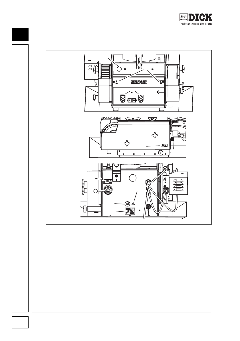
5.4 ::Signs on the grinding and honing machine
Figure 5.1 – Position of the signs
[1] Wear hearing protection and safety goggles when working
with the SM-200 TE grinding and honing machine.
[2] Direction of rotation on the grinding belt and polishing station
[3] Functional description for switches
[4] Note - moving parts under the cover.
[5] Direction of rotation for loosening the grinding belt.
[6] Disconnect the mains plug before opening the cover.
[7] Type plate
[8] Caution: electric shock - parts under the cover may be live.
SM-200 TE Grinding and Honing Machine
16
Page 17
Safety
9
10
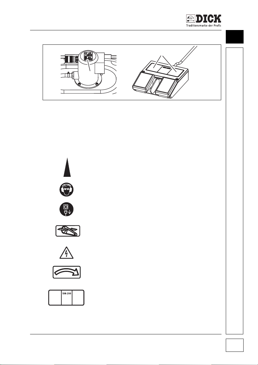
Figure 5.2 – Position of the signs
[9] Type plate on the cooling water tank
[10] Functional description of the foot pedal
5.5 Signage
Note:
Arrow on the machine housing for the correct
direction of rotation for the abrasives
Mandatory sign:
Use safety goggles
Mandatory sign:
Pull out the mains plug before opening.
Note:
Moving parts under the cover.
5
Warning sign:
Caution: high voltage
Note:
Direction of rotation to loosen the grinding belt.
Note:
Function of the foot pedal.
SM-200 TE Grinding and Honing Machine 17
Page 18

Safety
5
5.6 Covers
WARNING
Risk of injuries due to missing covers
The SM-200 TE grinding and honing machine may only be put
into operation when all covers and guard plates on the grinding
wheel, polishing wheel and grinding belt (see chapter 6.4 Covers)
are fully functional.
The SM-200 TE grinding and honing machine is covered with
sheet metal. The user cannot come into contact with moving parts
inside the machine.
The covers of the polishing wheel and wet grinding belt as well as
the guard plate of the grinding wheel are fastened with tommy
screws. They are very easy to remove for making adjustments or
modifications or for servicing. The belt safety guard on the wet
grinding belt must be mounted in such a way that the SM-200 TE
grinding and honing machine can be started.
SM-200 TE Grinding and Honing Machine
18
Page 19

Design and Function
6. Design and Function
6.1 Technical data
Motor and electrics
Power: 1.3 kW
Voltage: 3~400 V (three-phase)
Current intensity: 4.13 A
Frequency: 50/60 Hz
Type of operation: S3-70%
Degree of protection: IP 54
Connection: 3.5 m cable H05VV-F5G1.5 incl. 5-
pin CEE plug 16 A
Nominal speed: 2800 1/min (50 Hz)
Grinding wheel
Art. no.: 9 4601 010
Dimensions: Ø 200 x 60 mm
Rpm: 384 1/min (50 Hz)
Cutting speed: V
Grinding belt
Art. no.: 9 4601 120
Dimensions: 1250 x 60 mm - P120
Rpm (spindle): 1440 1/min (50 Hz)
Cutting speed: V
Polishing wheel
Art. no.: 9 4601 180
Dimensions: Ø 200 x 50 mm
Rpm: 1440 1/min (50 Hz)
Cutting speed: V
Machine dimensions / weights
Depth: 830 mm
Width: 650 mm
Height: 500 mm (without a stand)
Weight: 98 kg (without a stand)
= 4.0 m/s (50 Hz)
c
= 15.1 m/s (50 Hz)
c
= 15.1 m/s (50 Hz)
c
6
SM-200 TE Grinding and Honing Machine 19
Page 20

Design and Function
6
Cooling water unit
Volume of cooling water circulated:
Content of water tank 20 litres
Pump
Emissions sound pressure level
Sound emission in accordance with EN ISO 11201.
A-rated emissions sound pressure level at the work
area measured at idling speed L
Uncertainty K
A-rated emissions sound pressure level at the work
area measured when grinding a hand knife L
Uncertainty KpA; uncertainty in decibels: 3 dB (A)
Ambient conditions
Temperature
Storage: 3 - 40 °C
Operation: 3 - 30 °C
Usage: indoors
40 I/min
Power 0.12 kW
Degree of protection IP54
Connection 3~400 V (three-phase)
:73dB (A)
pA
; uncertainty in decibels: 3 dB (A)
pA
:77dB (A)
pA
SM-200 TE Grinding and Honing Machine
20
Page 21
14
11
10
12
8
9
15
16
17
18
1
6
4
5
3
2
7
13
Design and Function
6.2 Overview
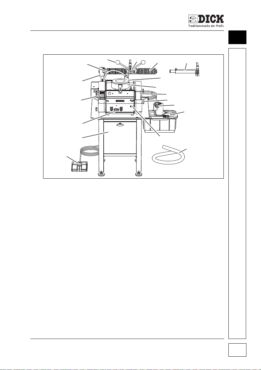
Figure 6.1 – SM-200 TE grinding and honing machine
[1] Cooling water supply
[2] Double grinding lever
[3] Mounting head
[4] Grinding arm (universal)
[5] Grinding arm (radial)
[6] Grinding wheel
[7] Guard ring
[8] Wet grinding belt
[9] Belt safety guard
[10] Mains plug
[11] Cooling water unit
[12] Mounting for belt grinding device
[13] Connecting hose
[14] Foot pedal
[15] Stand
[16] Control panel with On/Off switches
[17] Polishing wheel
[18] Grinding angle device
SM-200 TE Grinding and Honing Machine 21
6
Page 22
Design and Function
3
19
18
17
21
6
20
7
8
9
12
22
23
24
6
6.3 Design and Function
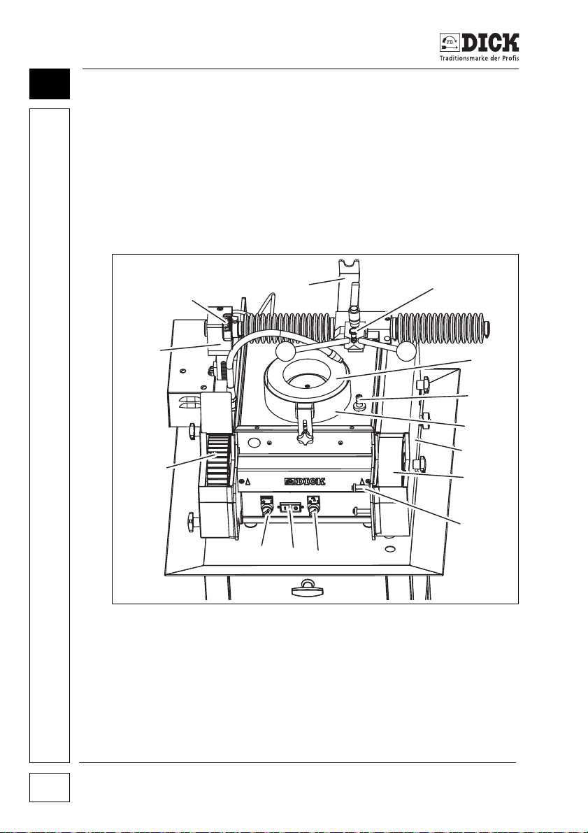
The SM-200 TE grinding and honing machine consists of a grinding angle device [18], a grinding wheel [6], a wet grinding belt [8],
a polishing wheel [17] and a cooling water unit [11]. The electric
motor in the housing of the machine powers all the abrasives at th e
same time via the gears, V-belt and spindle.
A buckle-resistant stainless steel frame accommodates the individual components of the SM-200 TE grinding and honing machine.
Figure 6.2 – Overview from above
[19] Scale head
[20] Mounting for dressing tool
[21] Grinding lever support
[22] On/Off switch for the abrasives
[23] Main On/Off switch
[24] On/Off switch for the cooling water
SM-200 TE Grinding and Honing Machine
22
Page 23

Design and Function
Grinding wheel
Knives, which are precisely positioned using the grinding arm [4]
or [5], are ground on the rotating grinding wheel. The cooling water
supply [1] provides cooling water. The guard ring [7] secures the
grinding wheel against inadvertent contact with the user and prevents water splashing.
Wet grinding belt
Knives are ground and deburred on the wet grinding belt [8]. The
grinding belt is guided over rollers and automatically tensioned.
The position of the grinding belt can be adjusted. The cooling water
flows through a channel from the tray below the grinding wheel to
the wet grinding belt. A marker shows the grinding belt's direction
of rotation. The belt safety guard [9] prevents access to the grinding belt during operation. The grinding and honing machine does
not start if the belt safety guard is not mounted.
Polishing wheel
Ground knives are deburred and polished on the polishing wheel
[17]. A marker shows the polishing wheel's direction of rotation.
6
Grinding angle device
The lift rod, scale head [19] and grinding angle display make up the
grinding angle device [18]. The grinding angle device is altered
vertically with a motor. The foot pedal controls the motor. The
grinding angle device can also be moved horizontally after loosening the clamping lever on the left-hand side of the machine. The
grinding angle device accommodates the grinding arm, which positions the knives over the grinding wheel. The vertical movement of
the grinding angle device changes the grinding angle.
Grinding arm
The grinding arm [4] is available in two different versions. Round
cutting edges can be sharpened with the radial grinding arm and
round and straight cutting edges with the universal grinding arm.
Grinding plates for clamping the knives are mounted on the mounting head [3] The grinding plate and double grinding lever [2] are
fastened here with the star handle.
SM-200 TE Grinding and Honing Machine 23
Page 24

Design and Function
6
The double grinding lever with the grinding plate is rotated into the
grinding lever support [21] on the back when workpieces are not
being machined. The grinding plate is mounted and the knives are
inserted here.
Cooling water unit
The grinding wheel and grinding belt are water-cooled. The cooling
water unit [11] provides the cooling water. The cooling water unit
on the SM-200 TE grinding and honing machine with a stand is
housed in the stand [15], otherwise it is provided. The cooling
water unit has a pump and the power is supplied indirectly via a
connection to the grinding and honing machine. A water tank contains the cooling water. The cooling water is fed to the grinding
wheel via the cooling water supply and runs off into the tray. The
cooling water is fed through a cooling water channel to the grinding
belt. The cooling water accumulates in the belt safety tank and is
fed back to the water tank through a drain and hose.
Grinding device holder
Position the UB3F or UB3F-XL belt grinding device (special accessory) on the mountings for the belt grinding device [12] on the front.
This accommodates the grinding plates that can be used to precisely
grind machine knives, such as cutter blades, on the grinding belt.
Dressing tool
Dress the grinding wheel if it is dirty or uneven. The bolt [20] next
to the grinding wheel holds the dressing tool for the grinding wheel
in place.
Mains plug
The power is supplied via the mains plug [10]. The pump of the
cooling water unit is powered by the SM-200 TE grinding and honing machine.
SM-200 TE Grinding and Honing Machine
24
Page 25
Design and Function
2
1
3
Control panel
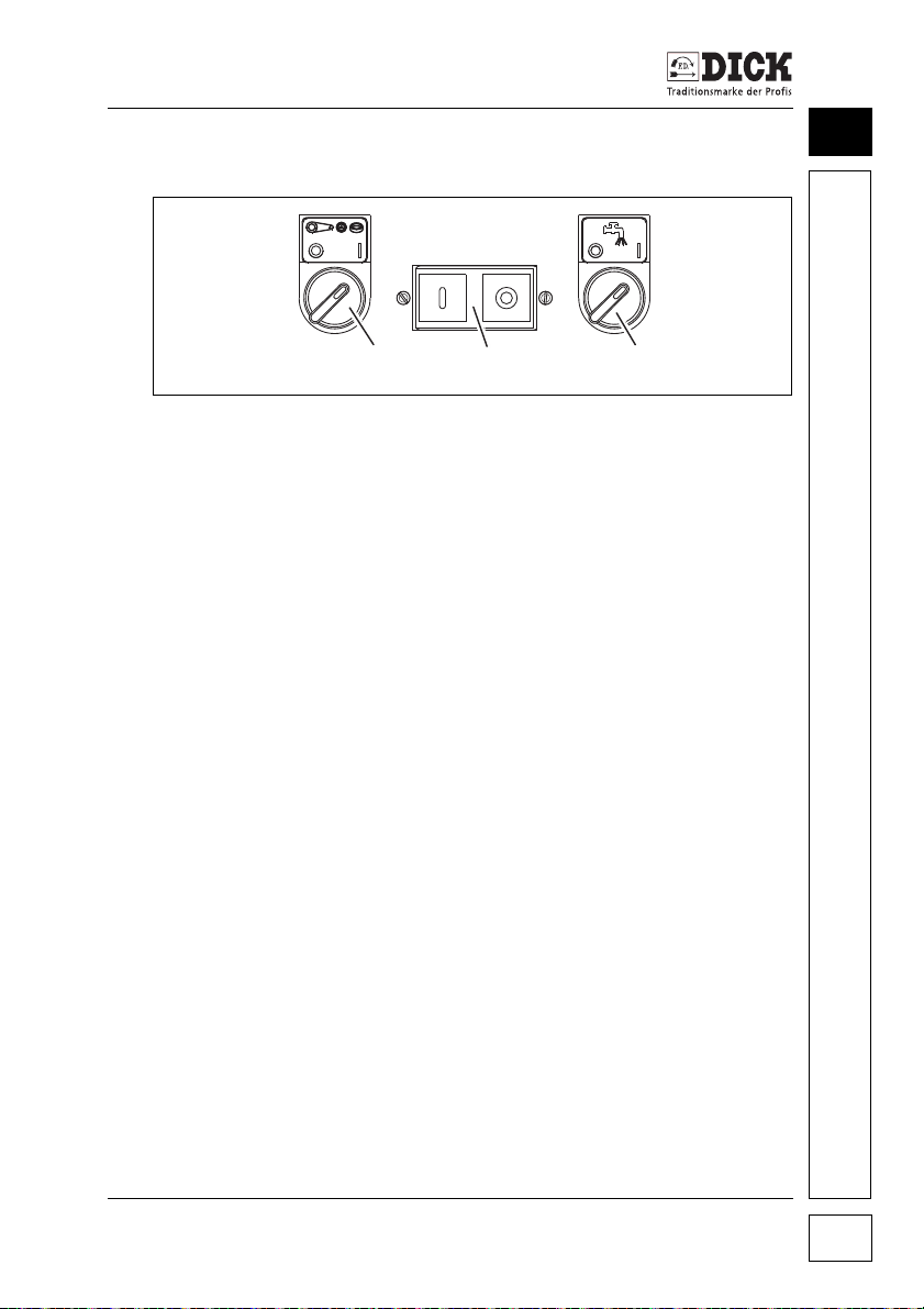
Figure 6.3 – Control panel
[1] Main On/Off switch for the machine
[2] On/Off switch for the abrasives
[3] On/Off switch for the cooling water
The control panel [16] contains the main On/Off switch [1] for the
SM-200 TE grinding and honing machine and one On/Off switch
each for the cooling water [3] and the abrasives [2], the grinding
wheel, wet grinding belt and polishing wheel.
Foot pedal
Adjust the grinding angle with the foot pedal [14]. The motor moves
the grinding angle device [18] vertically to do this. This changes
the setting angle of the knife on the grinding wheel. The left-hand
switch moves the grinding arm downwards and the right-hand
switch moves it upwards. The scale head [19] shows the current
grinding angle.
6
SM-200 TE Grinding and Honing Machine 25
Page 26
Design and Function
2
3
1
6
6.4 Covers
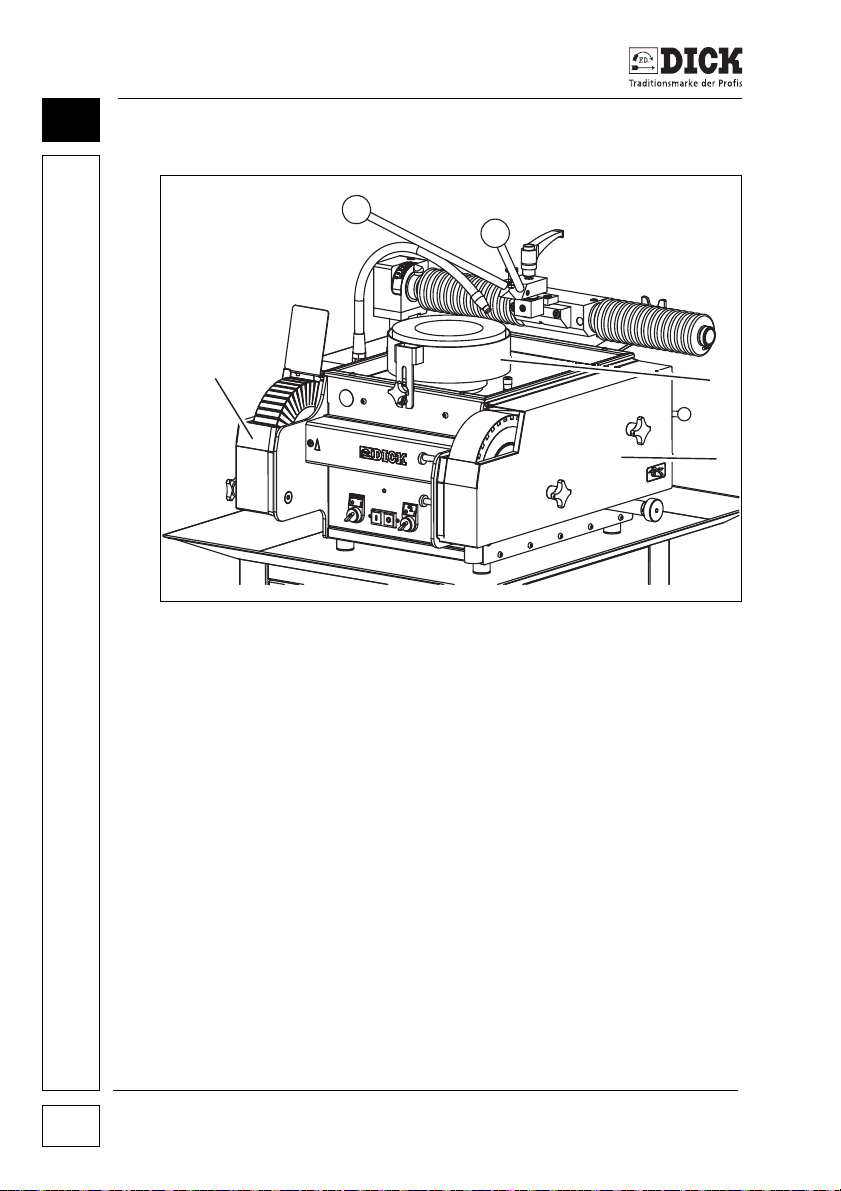
Figure 6.4 – Covering danger zones
[1] Polishing safety guard
[2] Guard ring
[3] Belt safety guard
The covers prevent access to the moving parts and protect the user.
Only operate the SM-200 TE grinding and honing machine with the
covers fully fitted.
SM-200 TE Grinding and Honing Machine
26
Page 27
Putting the Machine into Operation
1
1
7. Putting the Machine into Operation
Please take the following points into account when choosing
a place to set up the machine:
• The place must provide the space required for operating and
installing the machine as well as for maintenance and servicing work.
• A power connection with the necessary features is available.
7.1 Installing the machine
Place the SM-200 TE grinding and honing machine on a flat, nonslip surface to ensure that the grinding and honing machine does
not slip, tilt or move when it is being used.
Place the SM-200 TE grinding and honing machine without a stand
on a stable table or other substructure, which has sufficient stability
to carry the weight of the machine.
TAKE ACCOUNT OF THE ERGONOMICS
• Set up the SM-200 TE grinding and honing machine in such a
way that it is possible to work safely with an upright posture.
• Ensure there is good lighting at the work area.
7
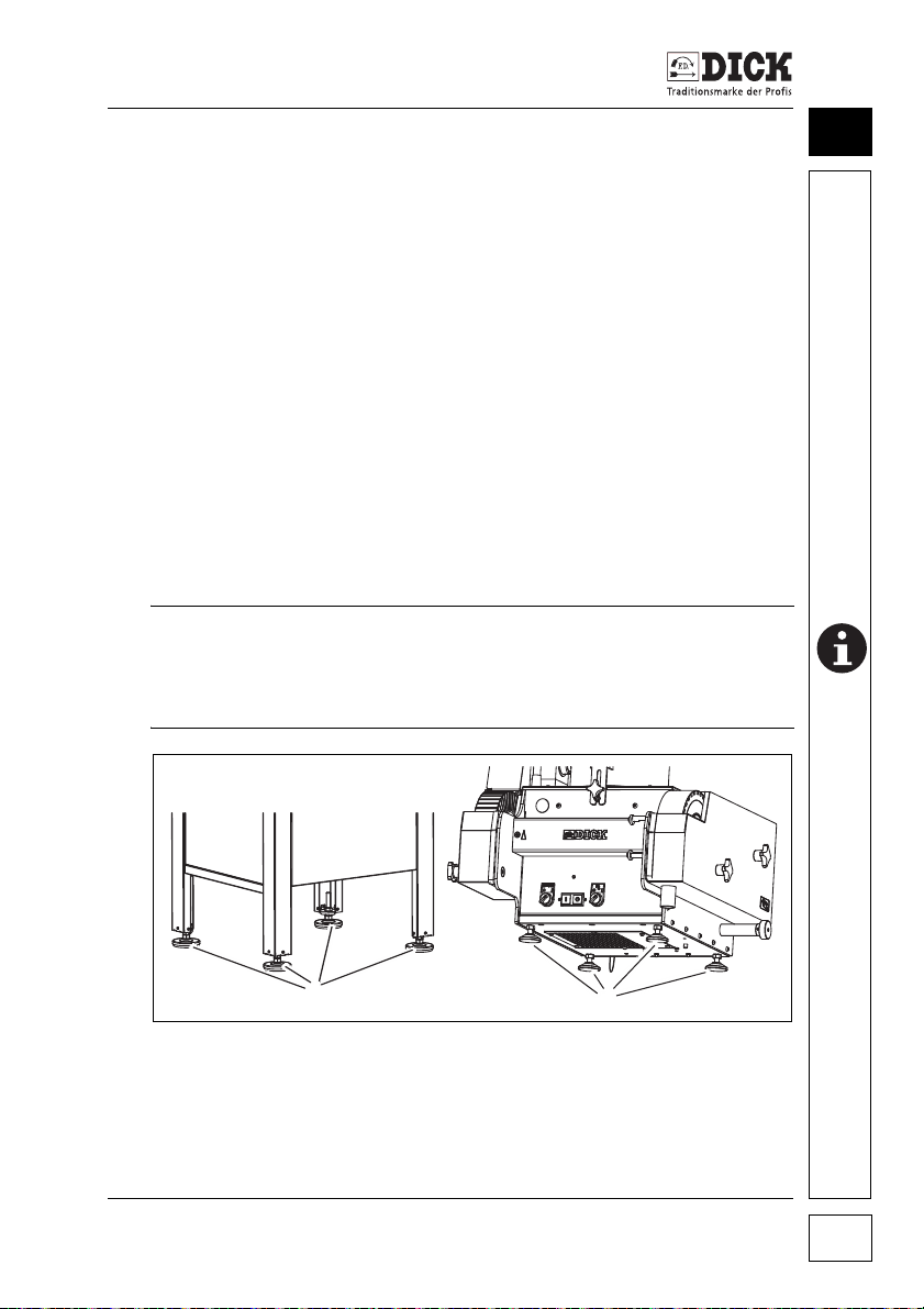
Figure 7.1 – Horizontal alignment by means of the machine feet
[1] Machine feet
1 Align the grinding and honing machine horizontally by means
of the height-adjustable machine feet [1].
SM-200 TE Grinding and Honing Machine 27
Page 28
Putting the Machine into Operation
3
2
1
7
7.2 Mounting the grinding arm
The grinding arm is supplied with the SM-200 TE grinding and honing machine. It is mounted on the scale head with the rounded
bearing side. The same steps are used for mounting the radial or
linear grinding arm.
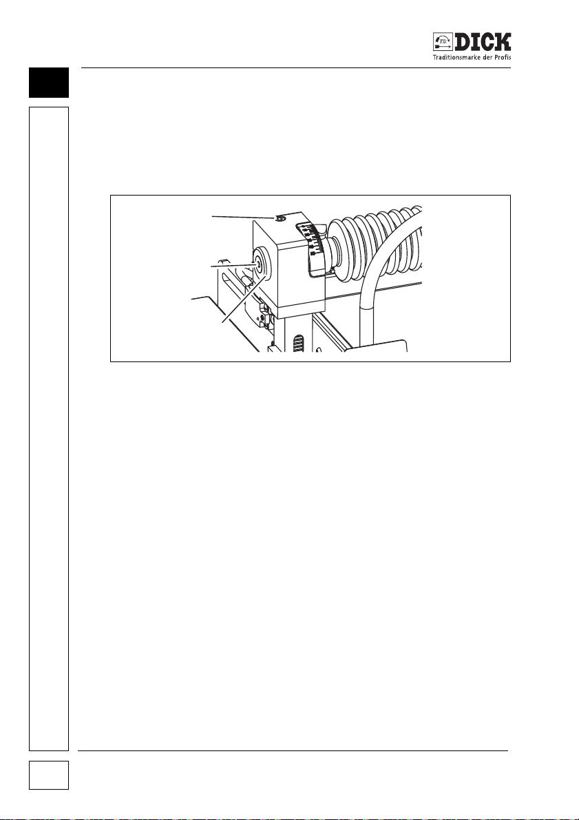
Figure 7.1 – Mounting the grinding arm
[1] Scale head clamping screw
[2] Grinding arm screw
[3] Bearing plate
1 Loosen the hexagon socket screw [2] on the grinding arm on
the bearing side and remove it together with the bearing plate
[3].
2 Insert the bearing side of the grinding arm through the mount-
ing of the scale head until the edge of the other side is visible.
3 First place the bearing plate on the bearing side of the grind-
ing arm, then tighten the hexagon socket screw [2]. The grind-
ing arm remains movable in the bearing.
4 Tighten the clamping screw [1] on the scale head. Tighten the
screw so that there is no play on the grinding arm, but the
grinding arm can move freely.
28
Disassemble the grinding arm before the grinding and honing
machine is ever transported in order to avoid damage. To do this,
perform the assembly steps in the reverse order.
SM-200 TE Grinding and Honing Machine
Page 29

Putting the Machine into Operation
7.3 Removing the dressing tool
The SM-200 TE grinding and honing machine is delivered with the
dressing tool mounted. Remove the dressing tool next to the grinding wheel before starting up the machine.
1 Loosen the clamping screw on the dressing tool.
2 Pull the dressing tool upwards out of the mounting.
3 Place the dressing tool in a suitable location.
7.4 Setting up the cooling water unit
The SM-200 TE grinding and honing machine with a stand is delivered with the cooling water unit fully installed.
The cooling water unit must be installed with the version without a
stand.
Position the cooling water unit at the SM-200 TE grinding and honing machine in such a way that the power supply, cooing water
hose and return hose can be easily attached.
The recommended position for the cooling water unit is below the
SM-200 TE grinding and honing machine.
Make the connections.
1 Place the water hose on the hose coupling below the cooling
water supply.
2 Place the return hose on the drain nozzle on the underside of
the belt safety tank. Guide the other end through the opening
in the lid into the water tank.
3 Place the power plug in the socket on the back of the
machine.
7
7.5 Filling the cooling water unit
Normal water suffices as cooling water.
1 Open the door on the stand.
2 Lift the cover with the pump out of the water tank.
3 Clean the water tank if necessary. To do this, remove the water
tank from the stand. Place the cleaned water tank in the stand.
4 Fill the water tank with cooling water to around 50 mm below
the rim.
SM-200 TE Grinding and Honing Machine 29
Page 30

Putting the Machine into Operation
7
5 Place the cover with the pump back on the water tank.
6 Close the door
Perform steps 2, 3, 4 and 5 for the SM-200 TE grinding and honing
machine without a stand.
7.6 Electrical connection
Damage to the SM-200 TE grinding and honing machine due
to mismatching connection data.
• Compare the electrical data of the grinding and honing
machine (see "Technical data" on page 19) with the connection data on site before starting up the machine.
• Connect the SM-200 TE grinding and honing machine only to
sockets with a clockwise rotating field and protective earthing.
• Connect the machine only when it is switched off.
1 Before connecting the SM-200 TE grinding and honing
machine to the mains supply, check that the switches for the
abrasives and for the cooling water pump are set to zero.
2 Connect the power.
NOTE
7.7 Performing test runs
Perform a test run for the abrasives and for the cooling water unit.
Test run for the abrasives
Check the direction of rotation of the abrasives. The grinding belt
and polishing wheel must rotate in the direction of the arrows for
the direction of rotation on the front of the machine. A second test
run checks the cooling water supply.
1 Press the I (ON) button on the main On/Off switch.
2 Set the switch for the abrasives to position I (ON).
The grinding and honing machine starts up.
3 Check the direction of rotation of the grinding belt and polish-
ing wheel.
4 Set the switch for the abrasives to position 0 (OFF).
SM-200 TE Grinding and Honing Machine
30
Page 31

Putting the Machine into Operation
A fault exists if the grinding belt and polishing wheel rotate in the
wrong direction. There is a risk of accidents. Switch off the machine
immediately and arrange for it to be checked by a qualified electrician. Repeat the test run if the fault has been rectified.
Correction of possible faults
CAUTION
A faulty power connection prevents the safe operation of the
machine.
If the running direction of the abrasives is incorrect, this may be
because the power is not connected properly. The mains plug is
connected with an anticlockwise rotating field. A qualified electrician can check and change the connection if necessary.
If this is not the cause of the fault, switch off the SM-200 TE grinding and honing machine, disconnect it from the mains and
arrange for it to be checked.
Test run for the cooling water unit
This checks the function of the cooling water unit. An adequate
amount of cooling water must be fed onto the grinding wheel and
the wet grinding belt. All lines and connections on the cooling water
line must be sealed. The routing of the cooling water to the wet
grinding belt and the return to the water tank must be secure.
7
1 Check that the valve on the cooling water supply is open (see
Figure 8.3 – Cooling water supply, pos.2).
2 Press the I (ON) button on the main On/Off switch.
3 Set the switch for the cooling water supply to position I.
The cooling water supply pump starts up.
SM-200 TE Grinding and Honing Machine 31
Page 32
Putting the Machine into Operation
7
4 Check that the cooling water is fed to the grinding wheel.
Unidentifiable faults can compromise the safe operation of
the machine.
A fault exists if the cooling water does not reach the grinding
wheel. There is a risk of accidents. Switch off the machine immediately and arrange for it to be checked by a qualified electrician.
Repeat the test run if the fault has been rectified.
5 Check that the supply line to the cooling water supply is tightly
sealed to the couplings.
6 Check that sufficient cooling water is fed to the wet grinding belt.
7 Check that the cooling water is returned to the water tank.
Correction of possible faults
A faulty power connection prevents the safe operation of the
machine.
If the cooling water does not reach the grinding wheel, this may be
because the power is not connected properly. The mains plug is
connected with an anticlockwise rotating field. A qualified electrician can check and change the connection if necessary.
If this is not the cause of the fault, switch off the SM-200 TE grinding and honing machine, disconnect it from the mains and
arrange for it to be checked.
CAUTION
CAUTION
If cooling water is leaking from the supply line, check the lines for
defects and that the couplings are tightly sealed.
If insufficient cooling water reaches the wet grinding belt, check
that the SM-200 TE grinding and honing machine is set up in a horizontal position.
If the cooling water collects in the belt safety tank, the return is
blocked and the cooling water circuit is interrupted. Switch off the
SM-200 TE grinding and honing machine and check the return.
SM-200 TE Grinding and Honing Machine
32
Page 33
Setting up the Machine
2
1
3
8. Setting up the Machine
Follow the safety instructions
Working with the SM-200 TE grinding and honing machine poses
a considerable safety risk. The risk of injury comes from the moving
parts and the knives to be ground.
• Follow the general safety instructions! See chapter 5. Safety,
page 11.
8.1 Switching on the grinding and honing machine
Do not switch on the SM-200 TE grinding and honing machine until
all preparations, modifications and adjustments for the current task
have been completed.
• Check that the abrasives are free of objects.
• Check that the machine is connected to the mains supply.
Switch the SM-200 TE grinding and honing machine on/off on the
control panel.
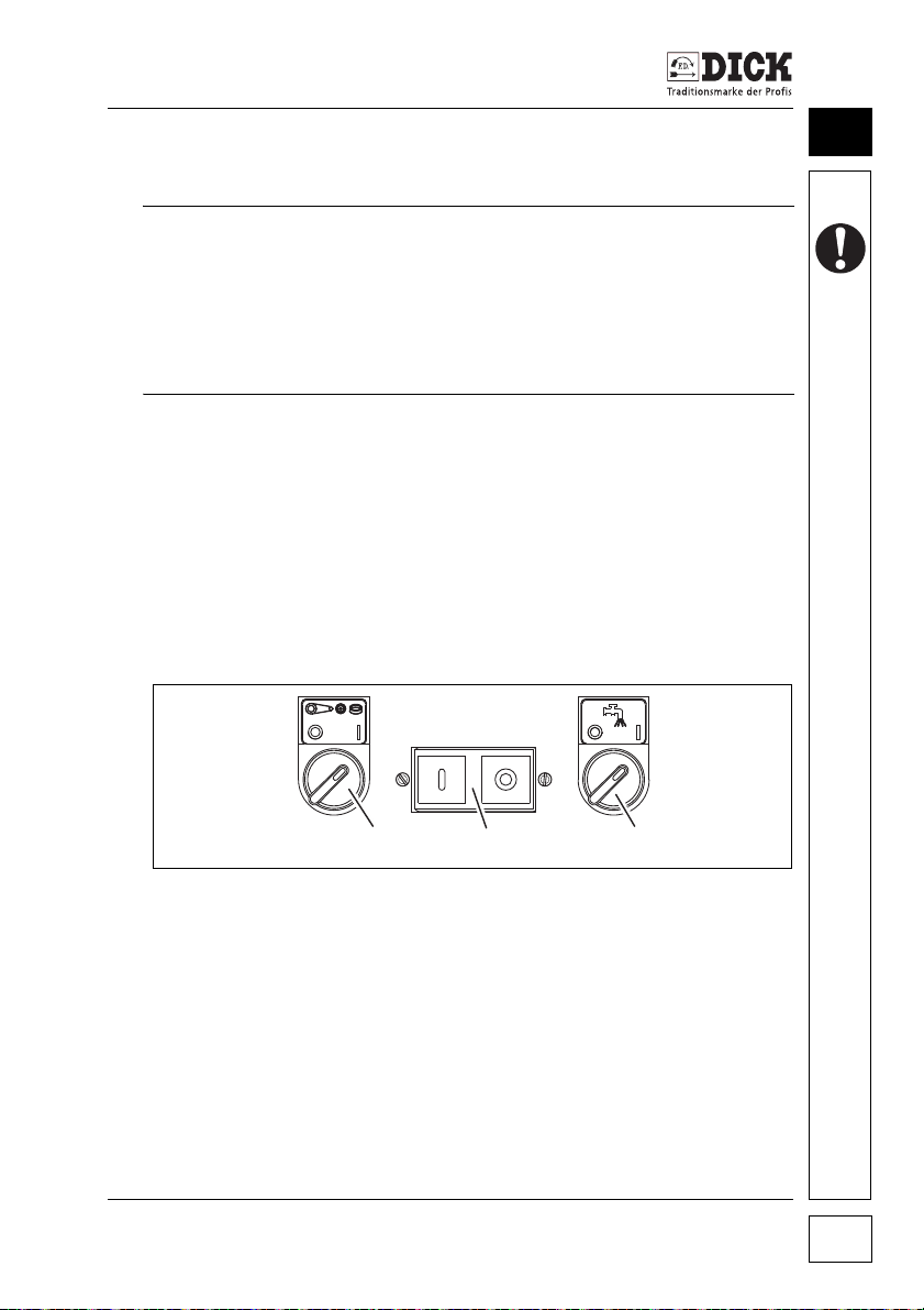
8
Figure 8.1 – Control panel
[1] Main On/Off switch on the SM-200 TE
[2] On/Off switch for the abrasives
[3] On/Off switch for the cooling water
Switching on the machine:
1 Press the I (ON) button on the main On/Off switch.
2 Set the On/Off switch for the abrasives to position I (ON).
The abrasives start up.
SM-200 TE Grinding and Honing Machine 33
Page 34
Setting up the Machine
8
Switch on the cooling water unit for working on the grinding wheel
or wet grinding belt.
3 Set the On/Off switch for the cooling water to position I (ON).
8.2 Switching off the grinding and honing machine
Switch off the grinding and honing machine if it is not used for a
longer period of time or is unattended.
1 Set the On/Off switch for the cooling water to position 0 (OFF).
2 Set the On/Off switch for the abrasives to position 0 (OFF).
3 Press the 0 (OFF) button on the main On/Off switch.
Pull out the mains plug if the grinding and honing machine is not
used for a longer period of time.
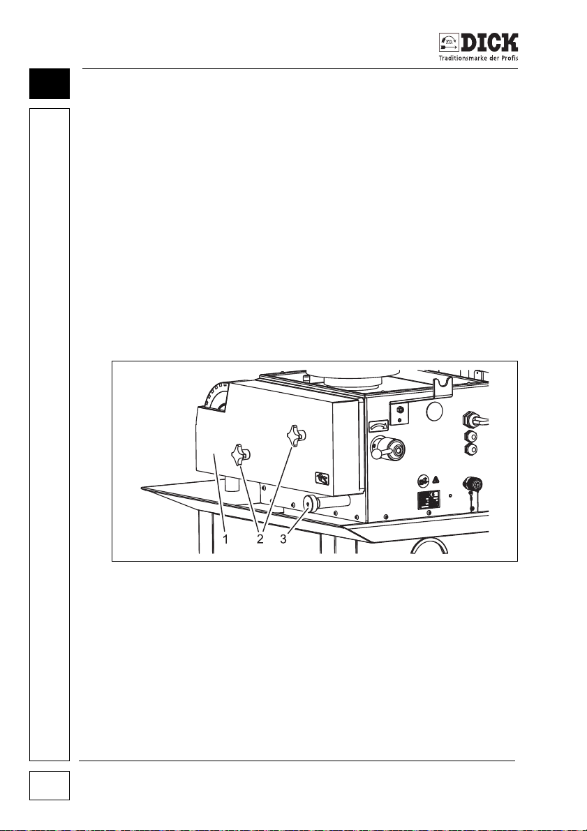
8.3 Adjusting the wet grinding belt
Figure 8.2 – Adjusting the wet grinding belt
[1] Belt safety guard
[2] Star handles
[3] Belt adjusting screw
The wet grinding belt must be adjusted when starting up the
machine and after the belt has been changed. The pressure of the
grinding on the wet grinding belt is not the same across the entire
width. One-side of the belt material can move. The belt does not
run in the middle of the roller.
SM-200 TE Grinding and Honing Machine
34
Page 35

Setting up the Machine
Set the position of the grinding belt on the roller on the belt adjusting screw [3].
If the grinding belt does not run symmetrically to the contact wheel,
first make a rough adjustment to the running direction.
1 Set the switch for the abrasives to position 0 (OFF).
If the grinding belt is still running, wait until it stops.
2 Loosen the star handles [2] and remove the belt safety guard.
3 Move the grinding belt on the front roller to the desired posi-
tion. Move the grinding belt a little by hand.
4 Preset the belt run with the belt adjusting screw.
- Rotating to the left, the grinding belt moves to the left.
- Rotating to the right, the grinding belt moves to the right.
5 The grinding belt must not run against the guard or the side
panel. The SM-200 TE grinding and honing machine is then
damaged.
If the running direction of the grinding belt is roughly in the correct
position, replace the belt safety guard and fasten it with the star
handles.
6 Move the switch for the abrasives briefly to position I (ON).
7 Check the belt movement when starting up the grinding belt.
The grinding belt must not touch the side panel or belt safety
guard.
Repeat steps 2, 3 and 4 if the grinding belt does not run in the correct position.
8 If the belt run is roughly in the correct position, set the switch
for the abrasives to position I (ON).
The abrasives start up.
9 Now make a fine adjustment to the grinding belt with the belt
adjusting screw [3].
- Rotating to the left, the grinding belt moves to the left.
- Rotating to the right, the grinding belt moves to the right.
10 Set the correct position.
8
SM-200 TE Grinding and Honing Machine 35
Page 36
Setting up the Machine
2
1
8
8.4 Setting the cooling water supply
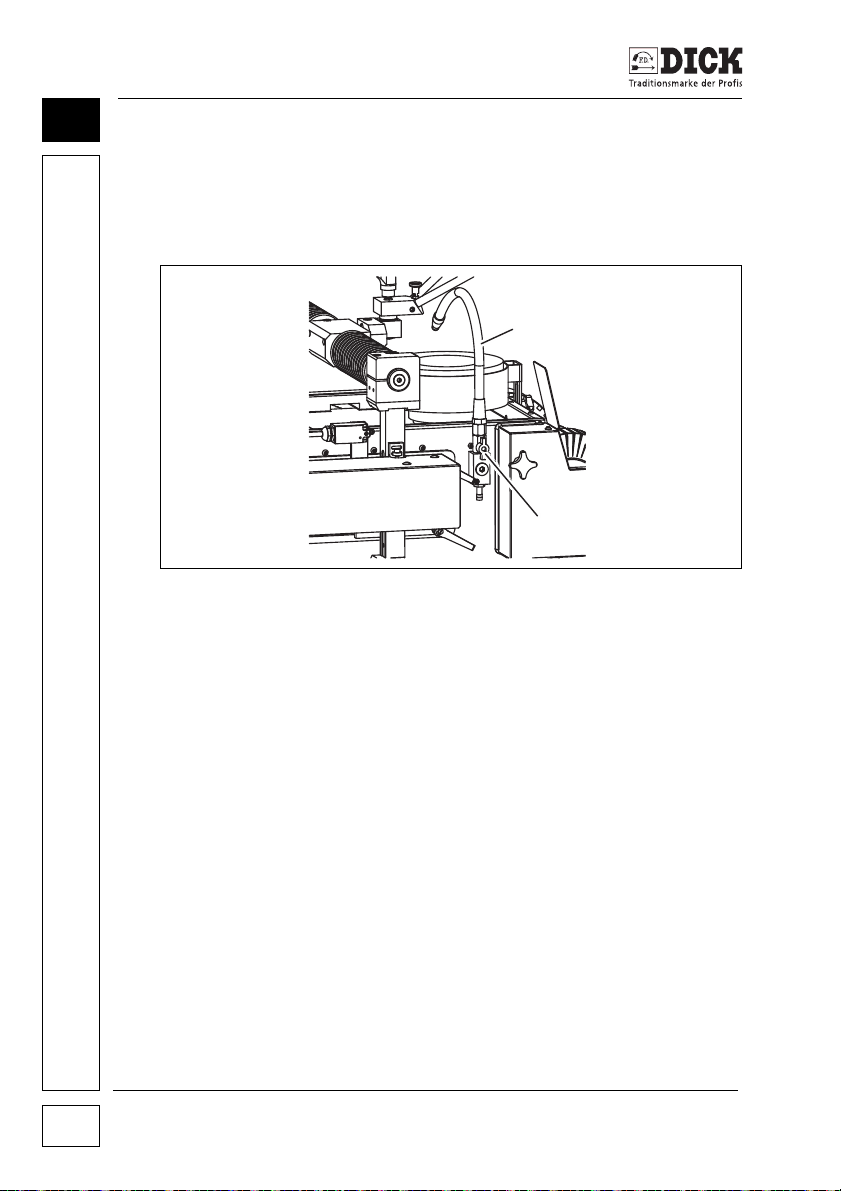
Set the cooling water supply hose for the grinding task. Set the
cooling water supply so that sufficient water reaches the grinding
wheel and the hose does not impede the grinding process.
Figure 8.3 – Cooling water supply
[1] Hose
[2] Valve
1 Set the On/Off switch for the abrasives to position 0 (OFF).
2 Set the On/Off switch for the cooling water to position I (ON).
3 Close the valve [2].
4 Set the hose [1] so that the water can run onto the grinding
stone without impeding the grinding process.
5 Open the valve again and check the result of the adjustments.
6 Set the On/Off switch for the abrasives to position I (ON).
SM-200 TE Grinding and Honing Machine
36
Page 37
Setting up the Machine
2
1
8.5 Setting the guard ring
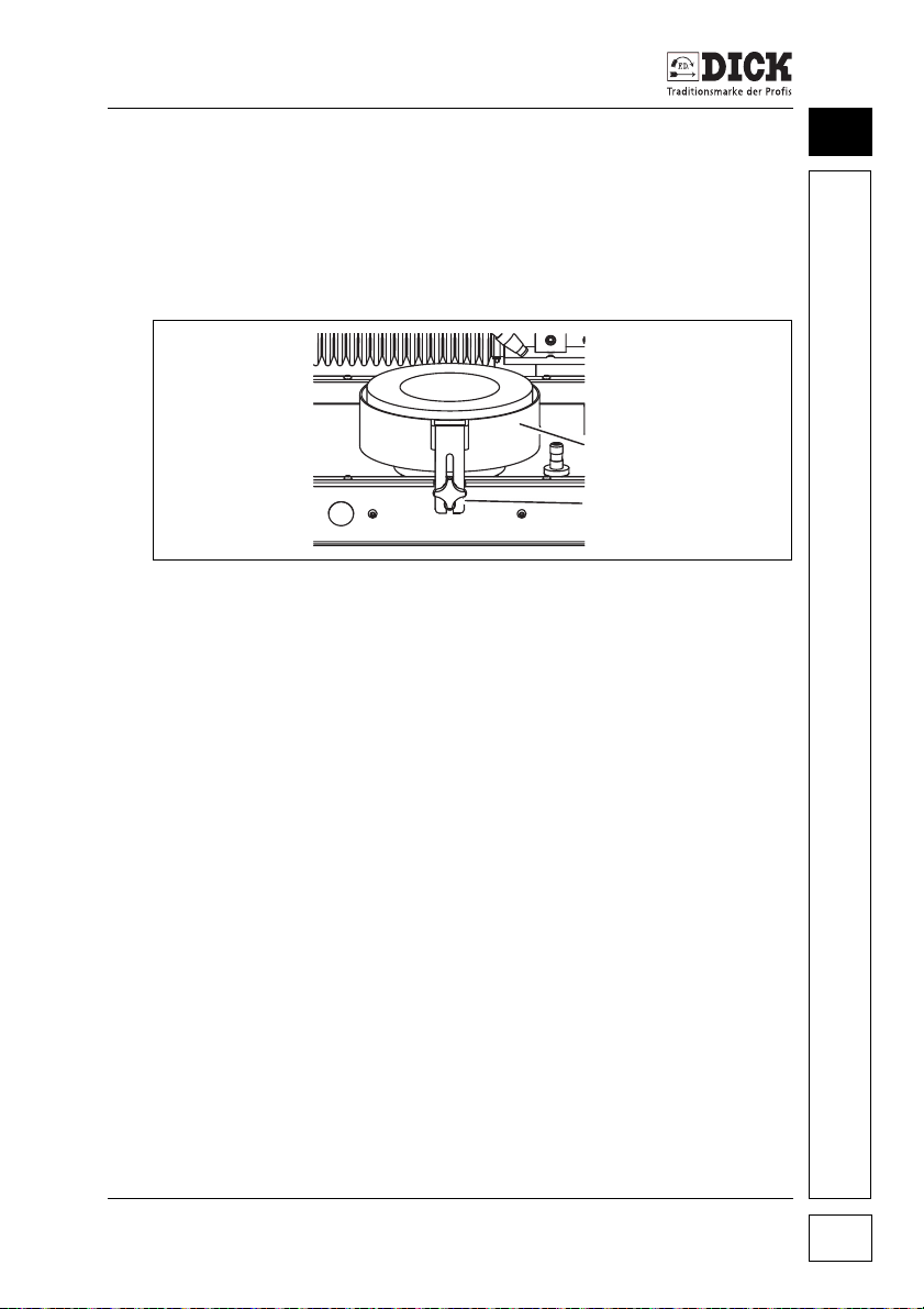
The guard ring prevents the user having any contact with the grinding wheel and stops water splashing.
The grinding wheel is subject to wear. The guard ring must not
impede the grinding process.
Figure 8.4 – Adjusting the guard ring
[1] Guard ring
[2] Star handle
1 Set the On/Off switch for the abrasives to position 0 (OFF).
2 Wait until the grinding wheel stops rotating.
3 Hold the guard ring with the hand.
4 Loosen the star handle. Place the guard ring in the correct
position. The grinding wheel must protrude 2 mm above the
guard ring.
5 Tighten the star handle.
8
8.6 Setting the universal grinding arm
The universal grinding arm provides a wide range of settings for
grinding different round and straight cutting edge shapes.
Knives with a straight cutting edge
The rotary function of the universal grinding arm is blocked and the
sliding function is released for grinding a knife with a linear
(straight) cutting edge.
SM-200 TE Grinding and Honing Machine 37
Page 38
Setting up the Machine
3
2
1
4
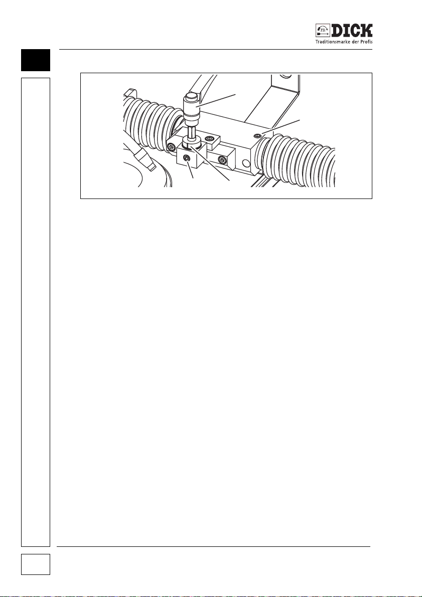
8
Figure 8.5 – Setting a straight cutting edge
[1] Clamping lever
[2] Screw
[3] Groove
[4] Screw
1 Loosen the screw [2].
2 Loosen the screw [4].
3 Rotate the clamping lever [1] on the universal mounting head
so that the groove [3] points to the front.
4 Clamp and fasten the universal mounting head in this position
with the screw [4].
Knives with a round cutting edge
The rotary function of the universal grinding arm is released and
the sliding function is blocked for grinding a knife with a radial
(round) cutting edge.
SM-200 TE Grinding and Honing Machine
38
Page 39

Setting up the Machine
III
II
I
XII
2
1
4
3
Figure 8.6 – Setting a round cutting edge
[1]
Line through the universal mounting head onto the grinding plate
[2] Screw
[3] Groove
[4] Screw
8
1 Loosen the screw [2].
2 Position the sliding carriage so that a line can be drawn
through the universal mounting head that lands on the grinding wheel between the 1 o'clock and 2 o'clock positions.
3 Tighten the screw [2].
4 Loosen the screw [4] and release the rotary function.
8.7 Setting the grinding radius on the universal grinding arm
The SM-200 TE grinding and honing machine with a universal
grinding arm can be set for different grinding radii. To do this,
mount the universal mounting head along with the clamping piece
on the front or the back of the universal grinding arm. Each position
enables a specific grinding radius range.
SM-200 TE Grinding and Honing Machine 39
Page 40
Setting up the Machine
2
1
8
Grinding radius/distance Position on the universal grinding
< 260 mm Front
> 260 mm Back
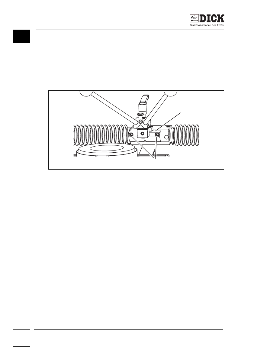
Figure 8.7 – Setting the grinding radius
[1] Clamping piece
[2] Screws
arm
Changing the grinding radius:
1 Remove the screws [2].
2 Remove the clamping piece [1] with the universal mounting
head from the grinding arm.
3
Remove the plugs from the holes on the back of the grinding arm.
4 Use the screws to fasten the clamping piece [1] with the uni-
versal mounting head on the grinding arm.
5
Use the plugs to block the holes on the front of the grinding arm.
8.8 Setting the radial grinding arm
The radial grinding arm provides a range of settings for grinding
round cutting edge shapes. The radial grinding arm positions the
universal mounting head in different positions in the direction o f t h e
grinding plate. The rotary function of the universal mounting head
is required for the grinding tasks.
SM-200 TE Grinding and Honing Machine
40
Page 41

Setting up the Machine
2
1
3
Figure 8.8 – Setting round cutting edge shapes
[1] Universal mounting head
[2] Screw
[3] Extension
Releasing the rotary function:
8
1 Loosen the screw [2] on the universal mounting head [1].
8.9 Setting the grinding radius on the radial grinding arm
The SM-200 TE grinding and honing machine can be set for different grinding radii. Four options are available for mounting the universal mounting head on the grinding arm.
Each option enables a specific grinding radius range by combining
the mounting position of the universal mounting head on the grinding arm and the use of an extension.
Grinding radius Position on the radial grinding
< 140 mm Front Yes
> 140 mm < 220 mm Front No
> 220 mm < 300 mm Back No
> 300 mm < 390 mm Back Yes
arm
Extension
SM-200 TE Grinding and Honing Machine 41
Page 42

Setting up the Machine
1
3
4
5
2
8
Figure 8.1 – Setting the grinding radius
[1] Clamping lever
[2] Universal mounting head
[3] Screw
[4] Extension
[5] Screw
Changing the grinding radius:
1 Loosen the screw [5].
2 Pull the universal mounting head [2] out of the grinding arm.
3 If the extension [4] is required - see table above - insert the
pin of the extension on the right-hand side of the grinding arm.
4 If the extension [4] is not required - see table above - insert
the universal mounting head [2] on the right-hand side of the
grinding arm.
5 Tighten the screw [5].
Mounting the universal mounting head [2] on the extension [4]:
1 Insert the pin of the universal mounting head in the extension.
2 Tighten the screw [3].
SM-200 TE Grinding and Honing Machine
42
Page 43

Setting up the Machine
8.10 Clamping the grinding plate
CAUTION
Risk of injury from knives and abrasives
• Set the On/Off switch for the abrasives to position 0 (OFF) for
the preparatory adjustments.
• Do not mount or remove the grinding plate with the workpiece
attached.
The guided sharpening of machine knives is performed with the
special grinding plate. The grinding plate will be produced individually by request to suit the workpiece.
The grinding plate replicates the shape of the knife edge on one
side. Fix the knife to the back of the grinding plate after using a
lever on the front to insert it into the knife-specific mountings.
Note
Use the correct grinding plate!
Sharpen the workpiece only with the appropriate grinding plate.
• If the grinding plate and workpiece do not fit together, this
may damage the workpiece, the grinding plate and the grinding and honing machine.
8
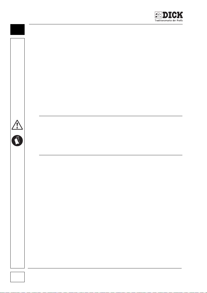
First clamp and set the right grinding plate on the grinding arm for
grinding a machine knife.
1 Lower the grinding arm with the foot pedal. Position the
mounting surface of the universal mounting head almost horizontally to the grinding wheel.
2 Loosen the two clamping levers of the grinding device.
3 Move the grinding device horizontally so that approximately 1
cm of the mounted grinding plate will subsequently rest on the
grinding wheel.
4 Clamp the two clamping levers of the grinding device.
5
Remove the clamping lever
6 Place the grinding plate without a workpiece on the shaft of
the universal mounting head. The other side of the grinding
plate rests on the grinding wheel.
[1]
on the universal mounting head.
SM-200 TE Grinding and Honing Machine 43
Page 44
Setting up the Machine
8
7 Place the hexagon socket of the double grinding lever on the
shaft of the universal mounting head. Align the hexagon
socket of the double grinding lever with the hexagon head of
the shaft.
8 Mount the clamping lever [1] onto the universal mounting
head again. Make sure that both hexagon sockets are
threaded.
9 Loosen the locking pin of the double grinding lever.
10 Rotate the grinding plate until the bolt engages.
11 Fasten the grinding plate and double grinding lever to the uni-
versal mounting head with the clamping lever [1].
Fasten the workpiece in the grinding plate after these initial steps.
Machine knives have a sharp cutting edge. They could cause
serious injuries.
• Always wear cut-resistant gloves when working with machine
knives.
• Work with due care and attention.
WARNING
1 Move the grinding arm to the middle height.
2 Place the double grinding lever in the fork of the grinding lever
support.
3 Lay the knife in the grinding plate and fasten with the rotary
lever of the grinding plate.
Checking the settings
Check the settings after this work. The contact point of the knife
edge on the grinding wheel should be positioned between 1 o'clock
and 2 o'clock.
SM-200 TE Grinding and Honing Machine
44
Page 45

Setting up the Machine
1 Place the knife edge on the grinding wheel with the double
grinding lever.
2 Raise the grinding arm to the maximum desired angle with the
foot pedal.
3 Check and adjust the contact point if necessary.
4 Loosen the clamping lever of the grinding angle device to
make an adjustment. Move the position of the grinding angle
device forwards or backwards.
5 Retighten the clamping lever or the grinding angle device
once the correct position is achieved.
The touchdown point moves forward a little when grinding smaller
angles.
6 Check the lateral position of the contact point after making this
adjustment. Adjust the lateral position of the contact point if
the position is incorrect here.
8.11 Setting up special solutions for circular blades
Flat circular blades with hole diameters >ø13.5 mm can be sharpened on the universal and radial grinding arm.
Special accessories are used for sharpening circular blades.
8
WARNING
Circular blades have a sharp cutting edge around the circumference. They could cause serious injuries.
• Always wear cut-resistant gloves when working with circular
blades.
• The knives rotate while they are being sharpened.
• Work with due care and attention.
NOTE
There are a very large number of versions of circular blades. Only
the typical special clamping devices are shown below. Special
clamping devices on request.
SM-200 TE Grinding and Honing Machine 45
Page 46

Setting up the Machine
8
Special accessories for sharpening circular blades:
• Adapter set for circular blades
- Centring pieces
- Clamping discs
• Special accessories depending on the diameter of the circular blade:
- Circular blade grinding arm ø 70 mm – ø 180 mm
- Circular blade grinding lever ø 180 mm – ø 500 mm
- Circular blade guard ø 200 mm – ø 500 mm
All special accessories require different set-up steps.
General preparatory work:
Prepare the universal grinding arm for radial grinding, see page 37.
1 Fasten the sliding carriage.
2 Release the rotary function of the universal mounting head.
Step 1 is not required on the radial grinding arm.
On both grinding arm versions:
3 Move the grinding angle device to the approximate position
required after loosening the clamping lever.
4 Choose a centring piece suitable for the circular blade from
the adapter set.
Now different work is required for the different knife sizes.
Circular blades ø 70mm – ø 180mm
1 Remove the universal mounting head.
2 Mount the circular blade grinding arm.
3 Tilt the circular blade grinding arm backwards. Loosen the
mounting screw on the underside with a hexagon socket key.
4 Remove the clamping disc.
5 Place the circular blade with the centring piece on the circular
blade grinding arm.
6 Mount the clamping disc again with the mounting screw.
7 Tilt the circular blade grinding arm forwards.
SM-200 TE Grinding and Honing Machine
46
Page 47

Setting up the Machine
8 Adjust the grinding angle with the foot pedal. Adjust the hori-
zontal and vertical position of the grinding device if necessary.
Contact point of the knife edge at approximately 1-2 o'clock on
the grinding wheel.
Circular blades ø 180mm – ø 200mm
1 Clamp the rotary axis on the universal mounting head, see
page 38.
2 Remove the double grinding lever of the universal mounting
head.
3 Place the stopper disc from the adapter set on the universal
mounting head.
4 Place the centring piece and circular blade on the universal
mounting head.
5 Screw together the clamping flange and circular blade grind-
ing lever.
6 Release the rotary axis on the universal mounting head again.
7 Adjust the grinding angle with the foot pedal. Adjust the hori-
zontal and vertical position of the grinding device if necessary.
Contact point of the knife edge at approximately 1-2 o'clock on
the grinding wheel.
8
Circular blades ø 200mm – ø 500mm
1 Remove the universal mounting head.
2 Mount the circular blade guard on the grinding arm.
3 Place the centring piece and circular blade on the circular
blade guard.
4 Screw together the clamping flange and circular blade guard.
5 Adjust the grinding angle with the foot pedal. Adjust the hori-
zontal and vertical position of the grinding device if necessary.
Contact point of the knife edge at approximately 1-2 o'clock on
the grinding wheel.
SM-200 TE Grinding and Honing Machine 47
Page 48
Machining Workpieces
9
9. Machining Workpieces
9.1 Sharpening machine knives
Machine knives have a sharp cutting edge. They could cause
serious injuries.
• Wear cut-resistant gloves when working with knives.
• Work with due care and attention.
The grinding process removes material on the knife. Grinding can
cause the knives in a cutter set to have different weights. The cutter shows an imbalance after the knife has been mounted. The different weight of the knives can be balanced on the grinding and
honing machine. Please follow the instructions of the machine
manufacturer. We recommend grinding to ±5 g if no information is
available.
Knives can be quickly resharpened on the SM-200 TE grinding
and honing machine with minimal wear with the special UB3F /-XL
belt grinding device accessory.
WARNING
NOTE
NOTE
Grind the machine knife according to the angle specified by the
knife manufacturer. Adjust the angle by lifting and lowering the
grinding arm and the grinding angle device.
9.2 Clamping and unclamping knives in grinding plates
Clamp the machine knife in a grinding plate in order to grind it. The
grinding plate must be a precise fit for the knife. The grinding plate
is mounted on the double grinding arm, see chapter “Clamping the
grinding plate”, page 43.
1 Place the double grinding arm in the support facing backwards.
2 Open the grinding plate clamping device.
3 Place the machine knife in the grinding plate.
4 Close the grinding plate clamping device.
SM-200 TE Grinding and Honing Machine
48
Page 49

Machining Workpieces
The knife can now be ground.
Remove the machine knife from the grinding plate
1 Place the double grinding arm in the grinding lever support
again to remove the machine knife.
2 Open the clamping device of the grinding plate and remove
the knife.
9.3 Sharpening knives
The machine knife is clamped in the grinding plate on the double
grinding arm.
1 Adjust the grinding angle on the grinding device.
2 Lift the workpiece off the grinding wheel with the double grind-
ing arm.
3 Set the On/Off switch for the abrasives to position I (ON).
4 Set the On/Off switch for the cooling water to position I (ON).
5 Lower the workpiece with the double grinding arm. Move the
area to be ground back and forth over the grinding wheel with
light pressure.
NOTE
Do not stop the movement of the workpiece on the grinding
wheel.
• There is a risk that the knife will overheat and the contour will
be damaged if the workpiece remains stationary on the grinding wheel.
9
6 Move the workpiece back and forth with the double grinding
lever.
NOTE
Follow the instructions of the knife manufacturer for grinding workpieces.
7 Repeatedly raise the workpiece and check the progress of the
grinding.
8 Complete the process when a burr has formed on the cutting
edge.
SM-200 TE Grinding and Honing Machine 49
Page 50

Machining Workpieces
9
Deburr the workpiece in the next step, see chapter “9.5 Deburring
and polishing machine knives”.
9.4 Machine knives with a bevelled contoured cutting edge
Regrind the contour specified by the manufacturer with a machine
knife. First regrind the cutting edge. Use the universal angle of 27°
if no information is available from the manufacturer.
The contoured cutting edge is produced after grinding the cutting
angle. Grind three bevels for basic sharpening. The following bevel
stages are tried and tested: 17°, 13° and 9°. These grinding stages
are marked in red on the scale of the grinding device.
The grinding of bevels is similar to the V-shaped edge. However,
a burr is only formed on the cutting edge when grinding the angle
of the cutting edge.
Round the bevels in the next step on the grinding stone or on the
wet grinding belt.
Grinding the angle of the cutting edge:
1 Set the grinding angle on the grinding device to 27°.
2 Lift the workpiece off the grinding wheel with the double grind-
ing lever.
3 On/Off switch for the abrasives to position I (ON).
4 Set the On/Off switch for the cooling water to position I (ON).
5 Lower the workpiece with the double grinding lever. Move the
area to be ground back and forth over the grinding wheel with
light pressure.
NOTE
Do not stop the movement of the workpiece on the grinding
wheel.
• There is a risk that the knife will overheat and the contour will
be damaged if the workpiece remains stationary on the grinding wheel.
SM-200 TE Grinding and Honing Machine
50
Page 51

Machining Workpieces
NOTE
• Follow the instructions of the knife manufacturer for grinding
workpieces.
6 Repeatedly raise the workpiece and check the progress of the
grinding.
7 Complete the process when a burr has formed on the cutting
edge.
Grinding the bevels:
1 Lift the workpiece off the grinding wheel with the double grind-
ing lever.
2 Set the grinding angle on the grinding device to 17°.
3 Lower the workpiece with the double grinding lever. Move the
area to be ground back and forth over the grinding wheel with
light pressure.
4 Complete the process once a smooth bevel has formed.
5 Repeatedly raise the workpiece and check the progress of the
grinding.
6 Repeat this step for the other bevels with the grinding angles
of 13° and 9°.
7 The bevelled cutting edge profile is pregrounded.
The bevels must be rounded in the next step. This is done on the
grinding stone or wet grinding belt.
Rounding on the grinding wheel:
Round the edges of the bevels by constantly changing the grinding
angle. Never set the grinding angle at a more obtuse angle than
the angle of the cutting edge or 25°.
1 Lower the workpiece onto the rotating grinding wheel with the
double grinding lever.
2 Constantly move the grinding arm on the grinding device up
and down between 20° and 5°, thus changing the grinding
angle. The grinding angle must not be at a more obtuse angle
than the angle of the cutting edge.
3 Lift the workpiece off the grinding wheel with the double grind-
ing lever.
9
SM-200 TE Grinding and Honing Machine 51
Page 52
Machining Workpieces
9
4 Check that a smooth surface has formed without edges.
5 Complete the process when a smooth bevelled contour has
formed on the surface.
6 Place the double grinding arm in the support facing backwards.
7 Take the knife out of the grinding plate.
8 Check the ground knife with the grinding template provided by
the knife manufacturer.
Rounding on a wet grinding belt
• Follow the instructions in chapter 9.7 “Grinding hand knives
and cleavers” for working with the wet grinding belt.
1 Place the double grinding lever in the support facing backwards.
2 Take the workpiece out of the grinding plate.
3 Grind the contoured surfaces on the wet grinding belt.
Constantly change the grinding angle.
4 The grinding angle must not be at a more obtuse angle than
the angle of the cutting edge. If the grinding angle gets closer
to the angle of the cutting edge, the grinding noise changes
slightly and the pressure of the water jet drops. Then switch to
a steeper grinding angle.
5 Complete the process when a smooth bevelled contour has
formed on the surface.
NOTE
9.5 Deburring and polishing machine knives
Deburr and polish the machine knives after sharpening. Use the
polishing wheel to do this.
WARNING
Risk of injury. Guide the knives by hand when deburring and
polishing. The knives are always sharp and can cause cuts.
• Never place knives against the cutting edge on the polishing
wheel.
• Wear cut-resistant gloves.
• Never grip the cutting edge.
• The workpiece can become hot.
SM-200 TE Grinding and Honing Machine
52
Page 53

Machining Workpieces
NOTE
The fins of the polishing wheel must not get wet.
Moisture damages the lamellar buffing wheel and makes it unusable.
Holding and guiding the knife
Hold and guide the knife by hand when polishing and deburring.
• Hold the knife close to the body.
• One hand holds the workpiece in such a way that it can be
polished safely on both sides by turning the hand. There is no
change to the grip on the workpiece during this process.
• The other hand changes the position when the workpiece is
rotated. It supports the other hand in guiding the workpiece.
The hand is placed on top of the workpiece in each case and
exerts the required pressure for the polishing. The cutting
edge of the knife is parallel to the polishing wheel shaft. The
surface to be polished is tangential to the polishing wheel
and at an obtuse angle to the previous bevel.
Applying polishing compound
Apply polishing compound to the lamellar buffing wheel for the polishing.
1 Press the block of polishing compound against the polishing
wheel while it is running.
• Apply the polishing compound shortly before starting up the
polishing wheel and using it to avoid contamination caused
by flying particles of compound.
• Repeat the process if the polishing effect wears off or the polishing compound is no longer present.
Deburring knives
Polish the ground cutting edge alternately on both sides for the
deburring.
1 Hold the workpiece in the hands and guide it onto the polish-
ing wheel.
2 Guide the knife over the polishing wheel.
9
SM-200 TE Grinding and Honing Machine 53
Page 54

Machining Workpieces
9
3 Rotate the workpiece so that both sides of the cutting edge
are machined evenly.
4 Hold the workpiece at a steep angle and under considerable
pressure on the polishing wheel at the beginning.
5 Repeatedly check the condition of the burr.
6 If a burr is no longer visible, guide the workpiece 3-4 times in
a flat position over the polishing wheel while applying pressure. This will polish the cutting edge.
Polishing the surface
1 The hands take their positions on the knife.
2 Guide the knife back and forth from side to side over the pol-
ishing wheel.
3 Exert only a little pressure.
• Prepare the ground surface by pregrinding it on the wet grinding belt to reduce the polishing time.
9.6 Sharpening circular blades
NOTE
WARNING
Circular blades have a sharp cutting edge around the circumference. They could cause serious injuries.
• Wear cut-resistant gloves when working with circular blades.
• Work with due care and attention.
Specific preparations are needed depending on the diameter of the
circular blade. Information regarding the steps are provided in
chapter “8.11 Setting up special solutions for circular blades”,
page 45.
Start sharpening the circular blades if all preparations have been
completed.
1 Lift the circular blade off the grinding wheel with the holder.
2 Press the I (ON) button on the main On/Off switch.
3 Move the grinding angle on the grinding device to 25° or to the
grinding angle specified by the manufacturer.
SM-200 TE Grinding and Honing Machine
54
Page 55

Machining Workpieces
4 Set the On/Off switch for the abrasives to position I (ON).
5 Set the On/Off switch for the cooling water to position I (ON).
6 Lower the circular blade onto the grinding wheel and apply
light pressure.
The circular blade immediately rotates automatically as a result of
the relative movement to the rotating grinding wheel. If this does
not happen, lift the circular blade again immediately and adjust the
settings.
7 Continue sharpening until a burr has formed on the circumfer-
ence of the blade.
8 Repeat the grinding on the other side on circular blades with
a symmetrical bevel. To do this, remove the circular blade
from the special clamping device, rotate it and mount it again.
Deburr the circular blade after sharpening it.
9 Lower the grinding arm slightly. Place the circular blade on the
grinding wheel while applying very little pressure to the grinding lever. The circular blade rotates. Remove the burr by alternately placing a sharpening steel on both sides of the cutting
edge at an angle of 15°-20°.
9
9.7 Grinding hand knives and cleavers
Machine hand knives and cleavers on the wet grinding belt and
polishing wheel.
NOTE
Dirty knives can irreparably damage the grinding belt and
polishing wheel. The surfaces can heat with long-term use.
• Only grind clean tools.
SM-200 TE Grinding and Honing Machine 55
Page 56
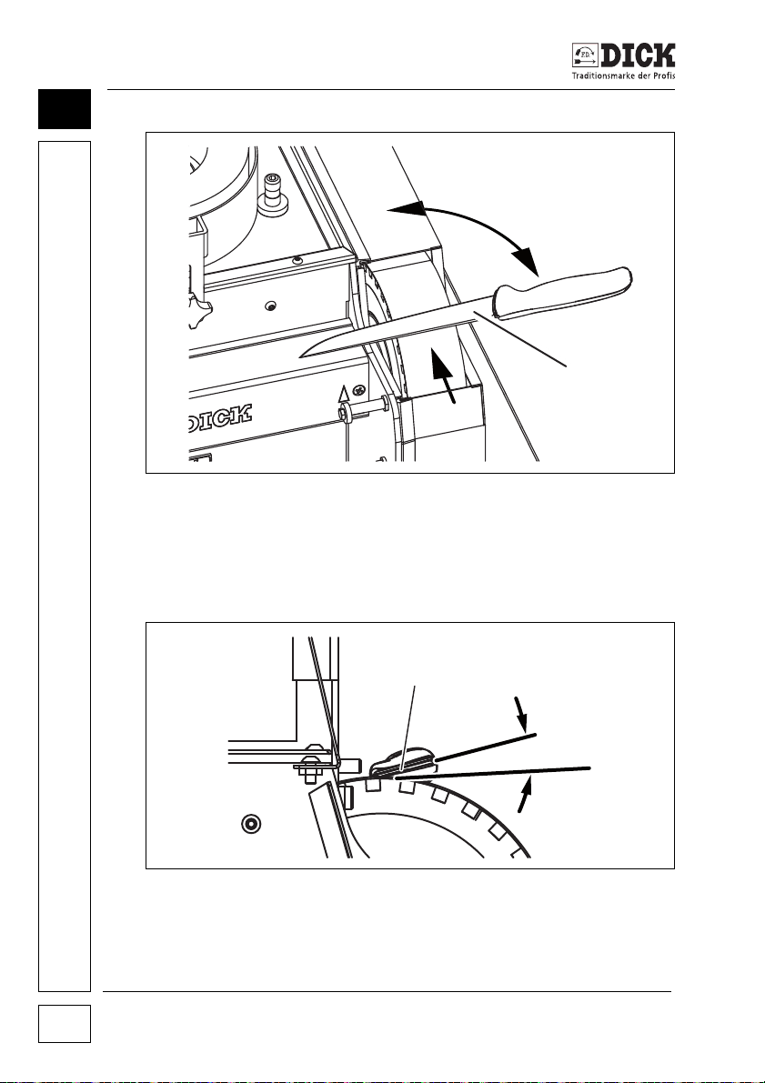
Machining Workpieces
1
3
2
5
4
9
Figure 9.2 – Grinding a knife
[1] Knife positioned at a right angle to the wet grinding belt
[2] Knife edge
[3] Direction of rotation of the wet grinding belt
Figure 9.2 – Grinding a knife
[4] Knife blade
[5] Positioning angle for the knife blade (15°) and cleaver (20°).
SM-200 TE Grinding and Honing Machine
56
Page 57

Machining Workpieces
WARNING
Risk of injury
The blade may cut into the grinding belt and be torn from the
hand.
• Never grind against the cutting edge.
1 Position the knife on the wet grinding belt so that the knife
edge [2] points in the direction of rotation of the wet grinding
belt [3].
2 Align the cutting edge of the knife horizontally so that it is posi-
tioned roughly perpendicular [1] to the grinding belt.
3 Position t he knif e blade [4] on the wet grinding belt at an angle
of approx. 15° [5]. Position the blade at approx. 20° with
a cleaver.
4 Grind the sides of the blade alternately when grinding until
a burr has formed over the entire surface.
NOTE
Workpieces heat during the grinding process
An over-heated cutting edge can anneal (loss of hardness) and
stress cracks can form on it.
• Always wet grind cutting tools.
9
NOTE
If the cutting edge has become thicker as a result of frequent grinding, the cutting edge thickness can be reduced again by grinding
the flat sides.
SM-200 TE Grinding and Honing Machine 57
Page 58
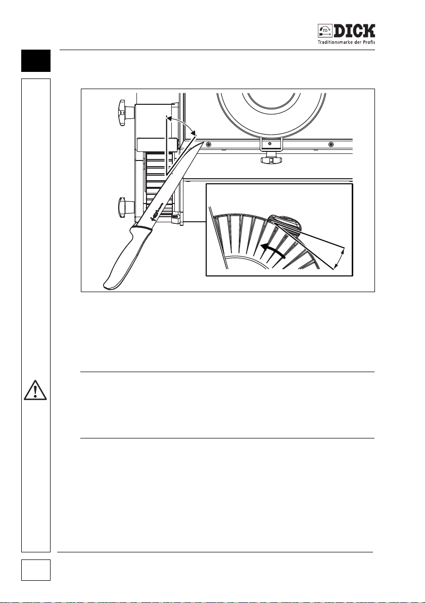
Machining Workpieces
1
2
9
9.8 Polishing workpieces
Figure 9.3 – Polishing a workpiece
[1] Positioning angle slanted relative to the running direction
(approx. 30°-60°)
[2] Positioning angle relative to the polishing wheel (approx. 20°)
WARNING
Risk of injury
The blade may cut into the polishing wheel and be torn from
the hand.
• Never polish against the cutting edge.
1 Hold the polishing compound against the polishing wheel
while it is running as required.
2 Position the workpiece slanted relative to the running direction.
3 Position the knife at the polishing wheel at a more obtuse
angle than for grinding.
4 Hone the knife until the burr has been completely removed
and the surface has the required polish.
5 Polish both sides of the blade alternately.
SM-200 TE Grinding and Honing Machine
58
Page 59

Servicing and Maintenance
10. Servicing and Maintenance
WARNING
Risk of injuries due to unauthorised or thoughtless switching
on or wrong spare parts
• Always pull out the mains plug before carrying out any maintenance or repair work on the belt grinding machine.
• Use exclusively original spare parts from Friedr. Dick GmbH &
Co. KG.
WARNING
Risk of injuries due to improper repair work
• Any repair work on electric components may only be carried
out by qualified electricians.
NOTE
After finishing all repairs and servicing work, check that all dismantled parts have been completely and correctly installed, especially
the covers.
Perform a test run lasting 1 minute after changing the grinding belt,
lamellar buffing wheel or grinding wheel and working on the ribbed
or V-belt.
10
Switch off the machine in case of unusual behaviour and remedy
the cause of the problem.
10.1 Cleaning the SM-200 TE grinding and honing machine
Clean the SM-200 TE grinding and honing machine after each use.
The grinding sludge is difficult to remove if it dries out.
We recommend lightly lubricating the machine with acid-free oil
after cleaning.
1 Remove the belt guards of the wet grinding belt.
2 Remove the polishing station cover.
3 Remove abrasion residues and grinding dust from the
SM-200 TE Grinding and Honing Machine 59
Page 60
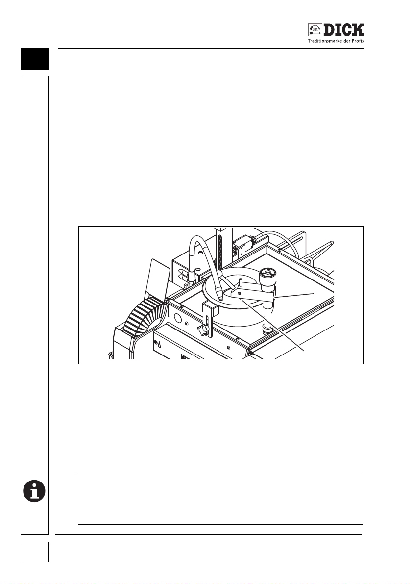
10
1
2
Servicing and Maintenance
machine and covers, e.g. with a brush.
4 Clean the water tank, remove the grinding sludge and replace
the water.
5 Lightly lubricate the grinding and honing machine - including
the inside of the covers.
6 Screw the covers on tightly again.
10.2 Dressing the grinding wheel
Clean or smooth dirty or uneven grinding wheels with the dressing
tool.
The dressing tool is supplied with the SM-200 TE grinding and honing machine.
Figure 10.4 – Dressing the grinding wheel
[1] Dressing tool
[2] Dressing diamond
1 Place the dressing tool [1] on the mounting next to the grind-
ing wheel.
2 Tighten the clamping screw on the dressing tool.
NOTE
• Before switching on the grinding and honing machine, make
sure that the dressing spindle and the diamond are not touching the grinding wheel.
SM-200 TE Grinding and Honing Machine
60
Page 61
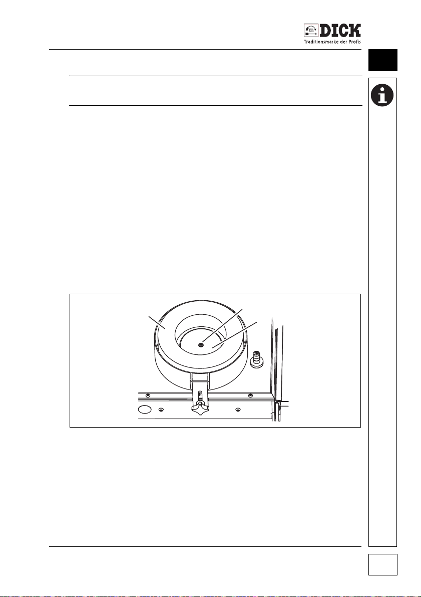
Servicing and Maintenance
2
1
3
NOTE
• Never dry dress the grinding wheel.
3 Press the I (ON) button on the main On/Off switch.
4 Set the On/Off switch for the abrasives and the On/Off switch
for the cooling water to position I (ON).
5 Pivot the dressing tool over the grinding wheel. Adjust the
knurled screw so that the dressing diamond touches the disc.
6 Move the dressing tool over the grinding wheel by hand.
Slightly adjust the knurled screw with the other hand with
every pivoting action.
7 Continue this dressing process until the grinding wheel is
clean and smooth.
8 Round the upper edge of the grinding wheel after the dressing
process. Use a dressing stone (accessory) to do this.
10.3 Changing the grinding wheel
10
Figure 10.5 – Changing the grinding wheel
[1] Grinding wheel
[2] Hexagon socket screw
[3] Clamping flange
Replace a worn or damaged grinding wheel immediately.
SM-200 TE Grinding and Honing Machine 61
Page 62
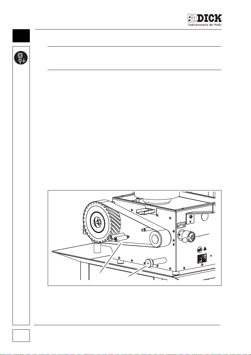
10
3
2
1
Servicing and Maintenance
NOTE
Pull out the mains plug before changing the grinding wheel on the
grinding and honing machine.
1 Pull out the mains plug on ther SM-200 TE.
2 Set the On/Off switch for the abrasives to position 0 (OFF).
3 Unscrew the hexagon socket screw [2] in the middle of the
clamping flange of the grinding wheel [1].
4 Remove the grinding wheel.
5 Remove the clamping flange [3] from the grinding wheel.
6 Clean the clamping flange and mounting flange.
7 Insert a new grinding wheel.
8 Position the clamping flange in the grinding wheel.
9 Lightly lubricate the hexagon socket screw.
10 Screw in and tighten the hexagon socket screw.
11 Plug in the mains plug on the SM-200 TE again.
10.4 Changing the wet grinding belt
Figure 10.6 – Changing the wet grinding belt on the SM-200 TE
[1] Wet grinding belt
[2] Belt adjusting screw
[3] Belt release lever
SM-200 TE Grinding and Honing Machine
62
Page 63

Servicing and Maintenance
Replace a worn or damaged grinding belt immediately.
NOTE
Pull out the mains plug before changing the wet grinding belt on
the grinding and honing machine.
1 Pull out the mains plug on the SM-200 TE.
2 Set the On/Off switch for the abrasives to position 0 (OFF).
If the grinding belt is still running, wait until it stops.
3 Loosen the star handles and remove the belt safety guard.
4 Rotate the belt release lever [3] in the direction of the arrow.
Remove the wet grinding belt [1].
The direction of rotation is marked with arrows on the inside of the
new grinding belt. These arrows must point in the same direction
as the arrow for the direction of rotation on the front of the grinding
and honing machine. The running direction of the grinding belt will
be correct if this is the case.
5 Position the new wet grinding belt.
6 Move the grinding belt on the front roller to the desired posi-
tion. Move the grinding belt a little by hand.
7 Preset the belt run with the belt adjusting screw [2].
- Rotating to the left, the grinding belt moves to the left.
- Rotating to the right, the grinding belt moves to the right.
8 The grinding belt must not run against the guard or the side
panel. The SM-200 TE grinding and honing machine is then
damaged.
If the running direction of the grinding belt is roughly in the correct
position, mount the belt safety guard and fasten it with the star handles.
9 Plug in the mains plug on the SM-200 TE.
10 Move the switch for the abrasives briefly to position I (ON).
11 Check the belt movement when starting up the grinding belt.
The grinding belt must not touch the side panel or belt safety
guard.
10
SM-200 TE Grinding and Honing Machine 63
Page 64

10
3
2
1
Servicing and Maintenance
Repeat steps 6, 7 and 8 if the grinding belt does not run in the cor-
rect position.
12 If the belt run is roughly in the correct position, set the switch
for the abrasives to position I (ON).
The abrasives start up.
13 Now make a fine adjustment to the grinding belt with the belt
adjusting screw [2].
- Rotating to the left, the grinding belt moves to the left.
- Rotating to the right, the grinding belt moves to the right.
14 Set the correct position.
Replace and adjust the wet grinding belt.
10.5 Changing the polishing wheel
Figure 10.7 – Changing the polishing wheel
[1] Polishing wheel
[2] Mounting nut
[3] Flange cover
Change the polishing wheel if the fins are damaged or worn.
SM-200 TE Grinding and Honing Machine
64
Page 65
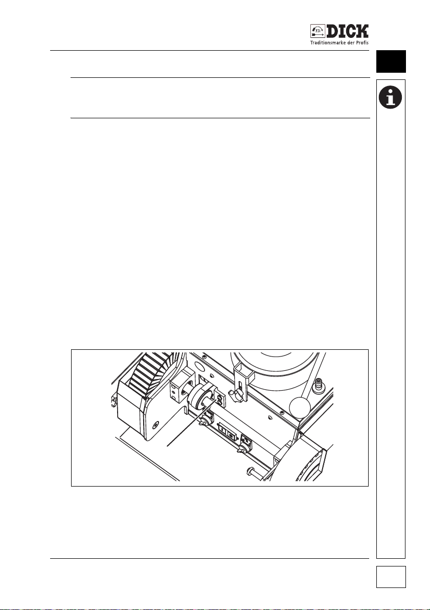
Servicing and Maintenance
1
NOTE
Pull out the mains plug before changing the polishing wheel on the
grinding and honing machine.
1 Pull out the mains plug on the SM-200 TE.
2 Set the On/Off switch for the abrasives to position 0 (OFF).
3 Loosen the star handles and remove the safety guard.
4 Loosen the mounting nut [2] of the flange cover [3] (right-hand
thread).
5 Remove the flange cover [3].
6 Remove the polishing wheel [1].
7 Clean the shaft.
8 Mount the new polishing wheel.
9 Mount the flange cover.
10 Tighten the mounting nut of the flange cover [3] (right-hand
thread).
11 Mount the safety guard and tighten the star handles.
12 Plug in the mains plug on the SM-200 TE.
10.6 Readjusting the ribbed belt
.
10
Figure 10.8 – Tensioning the ribbed belt
[1] Idler pulley
SM-200 TE Grinding and Honing Machine 65
Page 66

10
1
Servicing and Maintenance
Tension the ribbed belt if there is insufficient torque on the grinding
belt or polishing wheel.
NOTE
Switch off the grinding and honing machine SM-200 TE and pull
out the mains plug before working on the ribbed belt.
1 Pull out the mains plug on the SM-200 TE.
2 Set the On/Off switch for the abrasives to position 0 (OFF).
3 Remove the screws from cover plate.
4 Remove the cover plate.
5 Loosen the screws on the idler pulley.
6 Press and hold the idler pulley upwards.
7 Retighten the screws on the idler pulley.
8 Replace the cover plate.
9 Retighten the mounting screws on the cover.
10 Plug in the mains plug on the SM-200 TE.
10.7 Readjusting the V-belt
.
Figure 10.9 – Tensioning the V-belt
[1] Clamping screw
Tension the V-belt if there is insufficient torque on the grinding
wheel, grinding belt and polishing wheel.
SM-200 TE Grinding and Honing Machine
66
Page 67
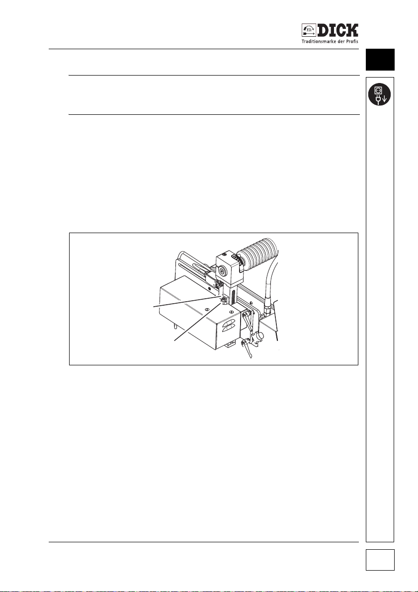
Servicing and Maintenance
2
NOTE
Pull out the mains plug before changing the polishing wheel on the
grinding and honing machine.
1 Pull out the mains plug on the SM-200 TE.
2 Set the On/Off switch for the abrasives to position 0 (OFF).
3 Remove the protective cover on the back of the machine.
4 The clamping screw is now visible. Rotate the clamping screw
with an SW 17 spanner and lightly tension the V-belt.
5 Replace the protective cover.
10.8 Adjusting the wedge on the lift rod
.
10
Figure 10.10 – Adjusting the wedge on the lift rod
[1] Wedge
[2] Adjusting screw
Wear can cause play in the transverse direction on the lift rod.
Check the wedge [1]. Replace the wedge if there is uneven wear.
If the wedge has worn evenly, reduce the play in the transverse
direction by altering the adjusting screw [2].
1 Move the lifting device to the top position with the foot pedal.
2 Place a drop of oil in the transition between the wedge and the
lift rod.
SM-200 TE Grinding and Honing Machine 67
Page 68

10
Servicing and Maintenance
3 Use an SW 5 hexagon socket key to screw the adjusting
screw into the housing until the play has disappeared.
4 Checking the adjustment: Exert pressure by hand on the scale
head in the transverse direction. Observe the film of oil in the
transition between the wedge and lift rod. There is no longer
any play if no change is noticeable here.
5 Move the lifting devi ce from the top position to the lowest posi-
tion in the next control step. If the wedge is too tight, the lift rod
will jam and the lower position will not be reached.
If the adjusting screw is completely screwed in after a few adjustments, position the collar of the adjusting screw in the overlying
groove of the wedge.
Replace the wedge if the adjusting screw is completely screwed in
again after the new positioning and making additional adjustments.
SM-200 TE Grinding and Honing Machine
68
Page 69
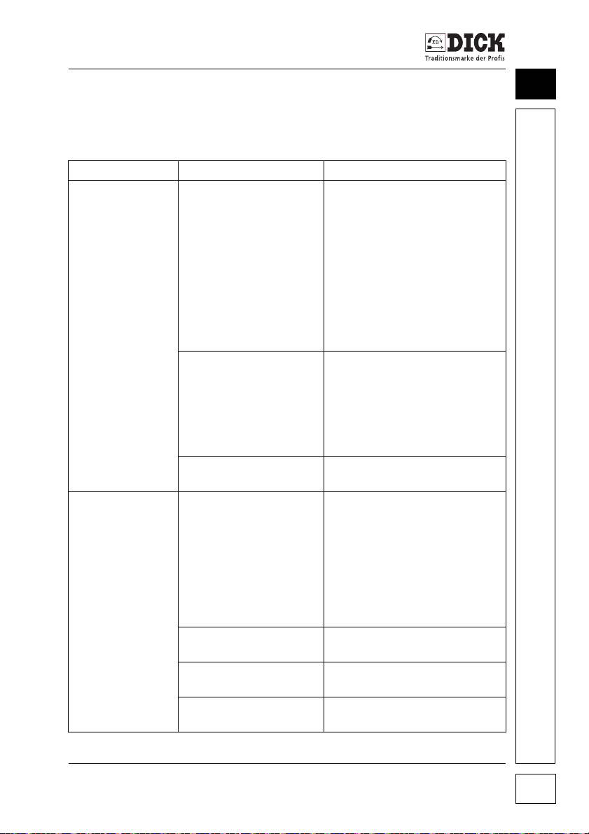
Servicing and Maintenance
10.9 Troubleshooting
Machine
Fault Cause Remedy
Motor and pump
do not work.
Grinding angle
device cannot be
moved.
Power supply is not
available.
Safety switch emits no
signal.
Main On/Off switch is
defective.
A neutral conductor is
needed to operate the
lifting motor.
Lift drive is sluggish. Check the lift rod for damage
Foot pedal is not connected.
Component is defective. Arrange for a qualified electri-
Check if there is a connection
to the mains supply.
Compare the power supply
parameters with the machine
data.
Check the lines and connections for damage
CAUTION: Disconnect the
machine from the power supply.
Belt safety guard must be
mounted.
Check that the magnetic bar is
attached to the guard.
Replace the safety switch if
necessary.
Check the main On/Off switch
and connections.
Ensure the connection with the
neutral conductor.
In power networks without a
neutral connector, connect to
the earth in the neutral conductor socket.
Caution: A safety function is
overridden.
or contamination.
Plug in the foot pedal connector plug.
cian to remedy the fault.
10
SM-200 TE Grinding and Honing Machine 69
Page 70

10
Servicing and Maintenance
Fault Cause Remedy
No cooling water. Insufficient water in the
tank.
Pump is not connected. Connect the pump to the desi-
Valve is closed. Open the valve.
Water pipe is defective
or blocked.
Defective component. Check the power supply and
Insufficient torque
on the grinding
belt or polishing
wheel in combination with a
whistling noise.
Insufficient torque
on the grinding
wheel and grinding belt or on the
polishing wheel.
Grinding belt cannot be adjusted.
Grinding belt cannot be tensioned.
Increased and
unusual noises.
Play in the lifting
device.
Too little tension on the
V-ribbed belt.
V-ribbed belt is worn. Replace the V-ribbed belt.
Dirt is blocking the free
running of the discs.
Too little tension on the
V-belt.
V-belt is worn. Replace the V-belt.
Component defect is
present.
Deflection pulley is
worn.
The deflection pulley
must be bevelled.
Mechanics are sluggish
or defective.
Contact wheel is worn. Replace the contact wheel.
Mechanics are sluggish
or defective.
Component damage
(bearings, loose screw
connection).
Wear on the wedge. Tighten the wedge.
Wear on the guidance. Replace the assembly.
Refill the water and clean the
tank if necessary.
gnated socket on the machine.
Clean the pump filter.
Clean or replace the waterbearing components.
replace the pump if necessary.
Increase the tension of the Vribbed belt.
Clean them so that they run
freely again.
Re-tension the V-belt.
Replace the defective component.
Replace the deflection pulley.
Repair the mechanics.
Repair the mechanics.
Localise the source of the
noise and replace the defective component if necessary.
SM-200 TE Grinding and Honing Machine
70
Page 71

Servicing and Maintenance
Circular blade grinding
Fault Cause Remedy
Circular blade
does not turn.
Sharpening position without relative movement.
Change the contact point.
10
SM-200 TE Grinding and Honing Machine 71
Page 72
11
Accessories and Spare Parts
11. Accessories and Spare Parts
11.1 Accessories
Description Order number
Universal belt grinding device
For sharpening sickle-shaped and linear machine knives
UB3F: 9 8302 001-A
UB3F-XL: 9 8311 000
UB3F-XL with a pivot arm: 9 8311 011
Wet grinding belt 60 x 1250 mm
P80: 9 4601 110
P120 (standard): 9 4601 120
P180: 9 4601 130
P400 9 4601 150
Wet grinding wheel Ø 200 x 60 x Ø 50 mm
P80: 9 4601 060
P120 (standard): 9 4601 010
Polishing wheel: 9 4601 180
Radial grinding arm: 9 8319 3603
Universal grinding arm: 9 8319 3602
Circular blade adapter discs
(Centring set), 12-piece, up to Ø 550 mm: 9 8324 120
Circular blade grinding lever: 9 8302 950
Circular blade grinding arm for circular blades Ø 70-Ø 180 mm: 9 8312 000
Circular blade guard Ø 200-Ø 500 mm: 9 8314 100
Dressing stone: 9 8181 060
Wet honing wheel: 9 4601 260
Polishing compound, 1 kg: 9 4700 040
Cooling water additive 1 l: 9 8404 311
Grinding plates: on request
SM-200 TE Grinding and Honing Machine
72
Page 73

Accessories and Spare Parts
CAUTION
Risk of accidents due to incorrect accessories.
Using accessories that are not matched to the SM-200 TE grinding
and honing machine constitutes an unassessable risk.
• Use exclusively F. DICK original accessories.
Use only F. DICK original accessories that are specified in the
operating instructions. The Friedr. DICK specialist advisers or the
supplier of the machine will be happy to help you if you have any
questions.
See "Ordering accessories and spare parts" on page 73 for ordering accessories.
11.2 Spare parts
The spare parts drawing and spare parts list are available at
www.dick.de.
11.3 Circuit diagram
The circuit diagram for the SM-200 TE grinding and honing
machine is available at www.dick.de.
11
11.4 Ordering accessories and spare parts
CAUTION
Risk of accidents due to incorrect accessories.
Using parts that are not matched to the SM-200 TE grinding and
honing machine constitutes an unassessable risk.
• Use exclusively F. DICK original accessories and F. DICK
original spare parts.
Use only F. DICK original accessories or spare parts that are specified in the operating instructions or diagrams and spare parts lists
at www.dick.de for the SM-200 TE grinding and honing machine.
SM-200 TE Grinding and Honing Machine 73
Page 74
11
Accessories and Spare Parts
Please proceed as follows to order accessories or spare parts:
• Select the desired parts from the accessories or spare parts
list.
• The order must include the following details:
1 Required quantities
2 Item number
3 Name
4 Machine type, machine article number, serial number, year of
manufacture (see type plate on back of machine).
• Please send your order for spare parts to your specialist dealer.
• You will find your specialist dealer at www.fdick.com/dealer
SM-200 TE Grinding and Honing Machine
74
Page 75

EC Declaration of Conformity
12. EC Declaration of Conformity
Manufacturer
Friedr. Dick GmbH & Co. KG
Esslinger Str. 4-10
73779 Deizisau
GERMANY
We hereby declare in sole responsibility that the following product, the
SM-200 TE Grinding and Honing Machine
with the serial number indicated on the type plate of the machine,
conforms to the following EC directives:
• EC Machinery Directive (2006/42/EC),
• EMC Directive (2014/30/EU),
• RoHS Directive (2011/65/EU).
European standards applied:
• EN ISO 12100:2010,
• EN 60204-1:2006,
• EN 61029-1:2009+A1:2011,
• EN 61000-3-2:2014,
• EN 61000-3-3:2013,
• EN 50581:2012,
• EN 55014-1:2006+A1:2009+A2:2011,
• EN 55014-2:2015.
The authorised representative responsible for compiling the technical documentation at Friedr. Dick GmbH & Co. KG is Mr Steffen
Uebele, Managing Director.
12
SM-200 TE Grinding and Honing Machine 75
Page 76

 Loading...