

Page 1
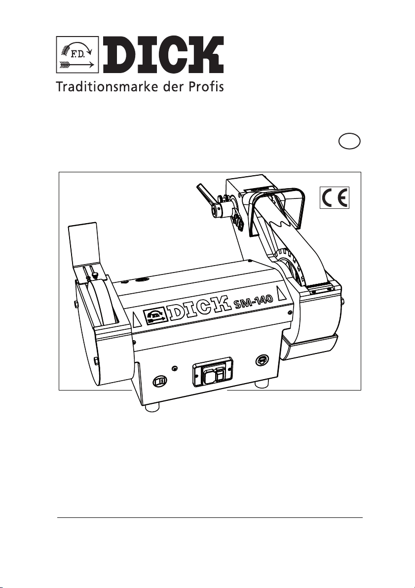
Operating instructions
(translation of original German version)
GB
SM-140
1~230 V - 50 Hz
Belt grinder
Art. No. 9 8240 001
Friedr. Dick GmbH & Co. KG · Postfach 1173 · 73777 Deizisau · GERMANY ·
Tel.: +49 (0)7153-817-0 · Fax: +49 (0)7153-817-218/-219 · Web: www.dick.de · Email: [email protected] ·
No. 98240 3852 Vers. 1/04-2013
Page 2

Manufacturer and customer service address
Friedr. Dick GmbH & Co. KG
Postfach 1173
73777 Deizisau
GERMANY
Copyright
© 2013 Friedr. Dick GmbH & Co. KG.
These operating instructions are protected by copyright; all rights are reserved.
These operating instructions may not be reproduced or copied, either in full or
in part, without the prior consent of Friedr. Dick GmbH & Co. KG. Infringements
are subject to compensation claims and can result in criminal prosecution.
Page 3
1. User Information.............................................................................4
1.1 General................................................................................................. 4
1.2 Symbols and conventions .................................................................... 4
1.3 Symbols................................................................................................ 5
2. Scope of Supply .............................................................................6
2.1 Package contents................................................................................. 6
2.2 Unpacking the belt grinder ................................................................... 6
3. Product Liability .............................................................................7
4. Environmental protection..............................................................7
5. Safety...............................................................................................8
5.1 Meaning of the warnings ...................................................................... 8
5.2 Intended use......................................................................................... 8
5.3 General safety instructions................................................................... 9
5.5 Covers................................................................................................ 12
6. Structure and Function................................................................13
6.1 Technical data .................................................................................... 13
6.2 Structure............................................................................................. 14
6.3 Function.............................................................................................. 15
6.4 Covers................................................................................................ 15
7. Putting into operation..................................................................16
7.1 Installing the belt grinder .................................................................... 16
7.2 Assembling the belt grinder................................................................ 16
7.3 Setting & adjusting the belt grinder .................................................... 17
7.4 Adjusting the belt alignment and running ........................................... 18
7.5 Adjusting and dismantling the water tank........................................... 19
7.6 Controls on the belt grinder ................................................................ 20
7.7 Switching on the belt grinder .............................................................. 21
7.8 Switching off the belt grinder .............................................................. 23
8. Machining workpieces.................................................................25
8.1 Grinding workpieces........................................................................... 25
9. Servicing and maintenance.........................................................29
9.1 Cleaning the belt grinder .................................................................... 29
9.2 Changing the grinding belt ................................................................. 30
10. Spare Parts ...................................................................................34
10.1 Spare parts drawing ........................................................................... 34
10.2 Ordering spare parts .......................................................................... 35
11. EC Declaration of Conformity .....................................................36
Belt grinder SM-140 3
Page 4

User Information
1
1. User Information
1.1 General
These operating instructions are part of the SM-140 belt grinder
with the serial number given on the type plate (the type plate is
located on the back of the belt grinder).
The operating instructions must be kept close at hand at all times.
It contains important information and instructions for safe, proper
and economic use of the belt grinder. It must have been read and
understood by each person before this person can be entrusted
with the following work using the belt grinder:
• putting into operation,
•operating,
• servicing.
The operating instructions must be followed during all work on and
with the belt grinder. Following them helps to prevent hazards,
to reduce repair costs and to increase the reliability and life of the
belt grinder.
The technical information and instructions for use in these
operating instructions are up-to-date and correct on delivery of the
belt grinder. Friedr. Dick GmbH & Co. KG reserves the right to
further develop the design and to make changes without notice.
All directional information is given from the view of the user.
1.2 Symbols and conventions
Instructions
Sequences of actions, which must be carried out in the given order
are given as a numbered list. Example:
1 Instruction step 1.
2 Instruction step 2.
Belt grinder SM-140
4
Page 5
User Information
Lists
Lists without a particular order that has to be followed are shown
as a list with bullet points or indent markings. Example:
• Property A
- Detail 1
- Detail 2
• Property B
1.3 Symbols
Important or particularly useful information is highlighted by way of
symbols so that it is readily recognised.
WARNING
This symbol denotes a warning, which must always be noted and
followed.
• For more information on the meaning of the warnings, refer to
the Safety chapter.
MANDATORY
This symbol indicates instructions, which must be complied with
for safety reasons.
1
NOTE, TIP
This symbol denotes general information, which contains user tips
and useful information.
Belt grinder SM-140 5
Page 6

Scope of Supply
2
2. Scope of Supply
2.1 Package contents
• Belt grinder
• Operating instructions
• Set of tools
• Polishing paste
2.2 Unpacking the belt grinder
Unpack the belt grinder immediately after purchase and check
whether it has any defects or transport damage. Also check the
package contents for complete scope of supply.
Report any defects immediately. Complaints made at a later date
can no longer be recognised.
Keep the invoice for the entire warranty period as proof of purchase.
In case of complaints, write to Friedr. Dick GmbH & Co. KG, enclose
the original invoice and a precise description of the defect(s).
Before returning the product, wait for the manufacturer's reply in
order to initiate the necessary steps.
Friedr. Dick GmbH & Co. KG does not pay any transport costs for
returns that have not been explicitly approved.
Keep the original box for any necessary returns, in order to prevent
transport damage.
INCORRECT CONNECTION DATA NOT IN LINE WITH
• Before starting up the belt grinder, compare the belt grinder's
electrical data (see "Technical data" on page 13) with the
connection data on site.
Belt grinder SM-140
6
DAMAGE TO THE BELT GRINDER DUE TO
THE SPECIFIED DATA
Page 7
Product Liability
3. Product Liability
All abrasives and other wearing parts are excluded from the
guarantee.
Changes to the belt grinder require the prior written approval of
Friedr. Dick GmbH & Co. KG.
Friedr. Dick GmbH & Co. KG does not accept any liability
whatsoever for defects or damage caused by incorrect assembly
or use of wearing, spare or accessory parts that are not original
DICK parts, or caused by improper handling.
For further details of the product liability and guarantee, please
refer to our General Terms and Conditions of Sale, Delivery and
Payment. These can be downloaded from
www.dick.de.
4. Environmental protection
Used machines, replacement parts and packaging are made of
recyclable materials. The owner is obliged to dispose of them
properly and in an environmentally friendly way, in accordance
with the legal regulations.
3
Belt grinder SM-140 7
Page 8
5
Safety
5. Safety
5.1 Meaning of the warnings
In these operating instructions, a differentiation is made between
warnings depending on the hazard:
DANGER
Imminent risk to life and the health of people.
• Causes serious injuries or death.
WARNING
Possibly imminent risk to the life and health of people.
• Could cause serious injuries or death.
CAUTION
Possibly dangerous situation
• Could cause minor injuries.
5.2 Intended use
The SM-140 belt grinder is solely designed for commercial use.
The SM-140 belt grinder can be used for hand-guided wet grinding
(sharpening) and polishing of cleaned knives and cutting tools.
Any other or additional use is deemed to be not as intended and
therefore misuse.
The grinding of materials which produce harmful or readily ignitable dusts is deemed to be misuse.
These include, for example:
Hierunter fallen zum Beispiel:
•Aluminium
• Magnesium
Belt grinder SM-140
8
Page 9
Safety
The belt grinder may not be switched on or operated in potentially
explosive atmospheres and is solely designed for use in dry rooms
at temperatures between +3 and +30 °C.
Only original spare parts and accessories from Friedr.
Dick GmbH & Co. KG may be used.
The owner is responsible for any damage caused by misuse.
5.3 General safety instructions
WARNING
Risk of injuries due to incorrect handling
Incorrect handling of the belt grinder can cause substantial injuries.
• The belt grinder may only be used by people who have read
and understood the operating instructions.
• The belt grinder may only be operated by people who are
familiar with the putting into operation/starting up, operation,
and servicing of machines and the relevant accident
prevention regulations, who are able to recognise the hazards
that occur during the grinder's use and who work reliably.
• The belt grinder may not be operated outside the given
power ranges (see "Technical data" on page 13).
• Operate the belt grinder only for the approved uses
(see "Intended use" on page 8).
5
Belt grinder SM-140 9
Page 10
Safety
5
WARNING
Risk of fire in the event of unsuitable environmental influences
Moisture (humidity) and water can cause a short circuit. Flying
sparks can cause flammable liquids and gases to ignite.
• Do not expose the belt grinder to rain or salt water.
• Do not use the belt grinder in a damp or wet environment.
• Ensure good lighting.
• Do not use the belt grinder near flammable liquids or gases.
Before each transport, switch off the belt grinder and remove the
mains plug from the socket.
Belt grinder SM-140
10
Page 11
Safety
3
4
1
2
5
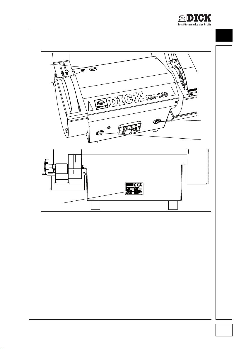
5.4 Information signs on the belt grinder
5
Figure 5.1 – Information on the belt grinder
[1] Before opening the cover, remove the mains plug from
the socket
[2] Danger! Electric shock – components under the cover
canbelive
[3] Wear hearing protection and safety glasses or goggles when
working with the belt grinder
[4] Read the operating instructions before starting up
[5] Type plate
Belt grinder SM-140 11
Page 12
Safety
6
5
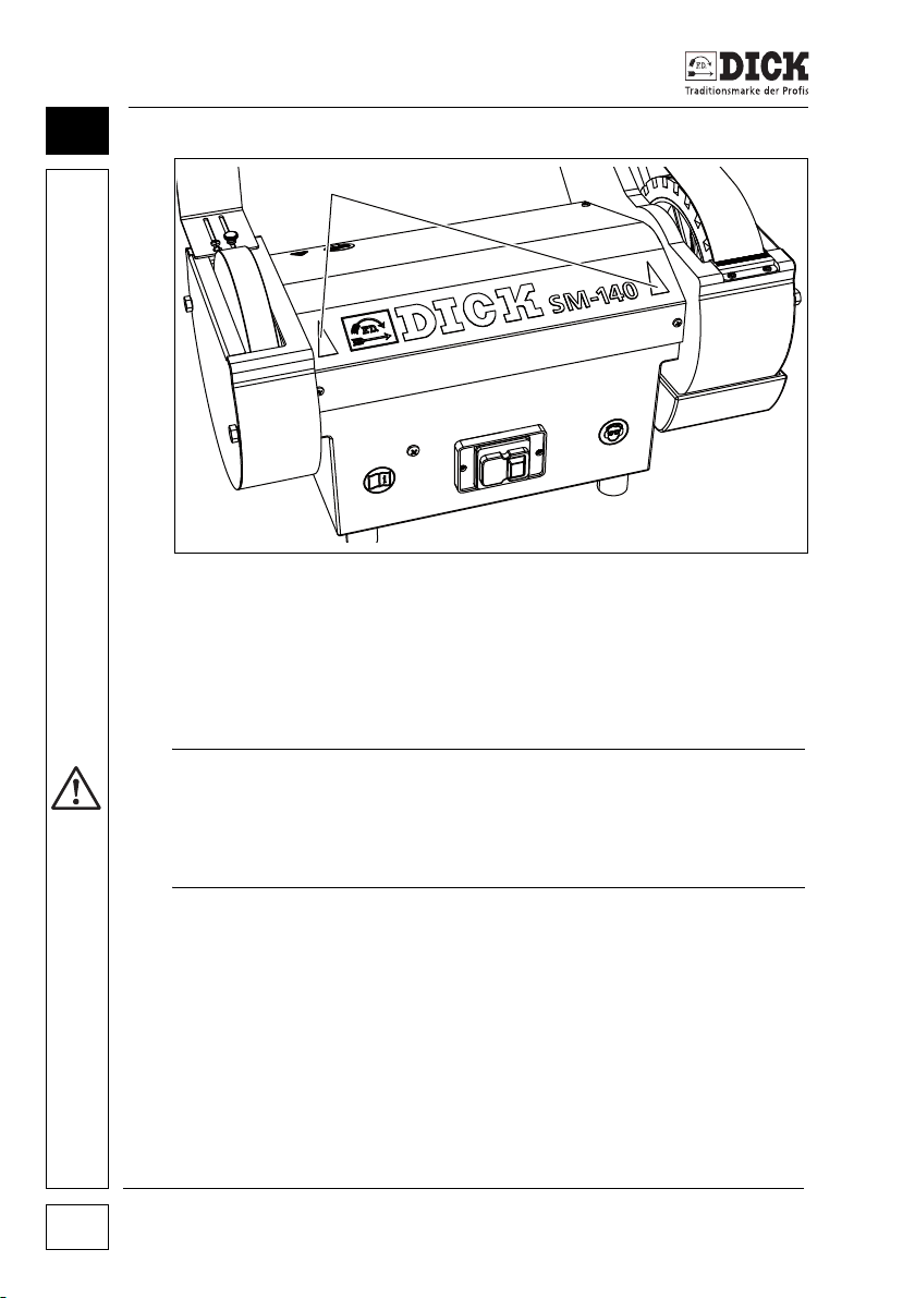
Figure 5.2 – direction of rotation of the belt grinder
[6] Rotational direction information on the polishing wheel and
grinding arm
5.5 Covers
Risk of injuries due to missing covers
The belt grinder may not be started up until all covers and guards
on the polishing wheel and grinding arm (Figure 6.2 – Structure
and Function) are fully functional.
Belt grinder SM-140
12
WARNING
Page 13

Structure and Function
6. Structure and Function
6.1 Technical data
Motor and electrics
Power: 0.25 kW
Voltage: 1~230 V
Current intensity: 1.7 A
Frequency: 50 Hz (60 Hz)
Degree of protection: IP 54
Type of operation: S2 - 60 min
Connection: 1.8 m cable H05VV-F3G1.0
CEE 7/7 Euro earthing pin plug
Nominal speed: 1400 rpm (50 Hz)
Grinding belt
Dimensions: 1000 x 50 mm
Cutting speed: V
Polishing wheel
Dimensions: 200 x 25 x 16 mm
Cutting speed: Vc = Vc = 14.3 m/s (50 Hz)
= 14.3 m/s (50 Hz)
c
with polishing wheel diameter 200 mm
6
Machine dimensions / weights
Depth: 446 mm
Width: 563 mm
Height: 416 mm
Weight: 19.5 kg
Emissions sound pressure level
Sound emissions to EN ISO 11201 during the grinding of boning knives.
Emission sound pressure level in idle state L
Uncertainty K
Emissions sound pressure level L
Uncertainty K
:3dB (A)
pA
:77dB (A)
pA
:3dB (A)
pA
:73dB (A)
pA
Belt grinder SM-140 13
Page 14
Structure and Function
1
2
3
4
56
7
8
9
10
6
6.2 Structure
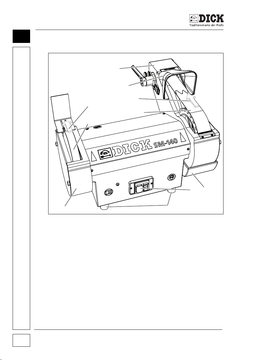
Figure 6.1 – Structure of the belt grinder
[1] Grinding arm
[2] Sprayhood
[3] Direction of rotation of the grinding belt
[4] Grinding belt
[5] Water tank
[6] Switch
[7] Machine base
[8] Polishing station
[9] Polishing wheel
[10] Direction of rotation of the polishing wheel
Belt grinder SM-140
14
Page 15
Structure and Function
1
3
2
4
6
5
7
8
6.3 Function
The belt grinder consists of two functional groups: A grinding
arm [1] with the grinding belt [4] and a polishing station [8] with
polishing wheel [9]. The polishing station is mounted on the left and
the grinding arm is mounted on the right of the housing. The switch
[6] and the four machine bases [7] are fixed to the housing The
specified direction of rotation for the polishing wheel [9] and the
grinding belt is marked on the belt grinder. A water tank [5] is
attached to the grinding arm to cool the tool to be ground. Surplus
water is collected by the sprayhood [2].
6.4 Covers
6
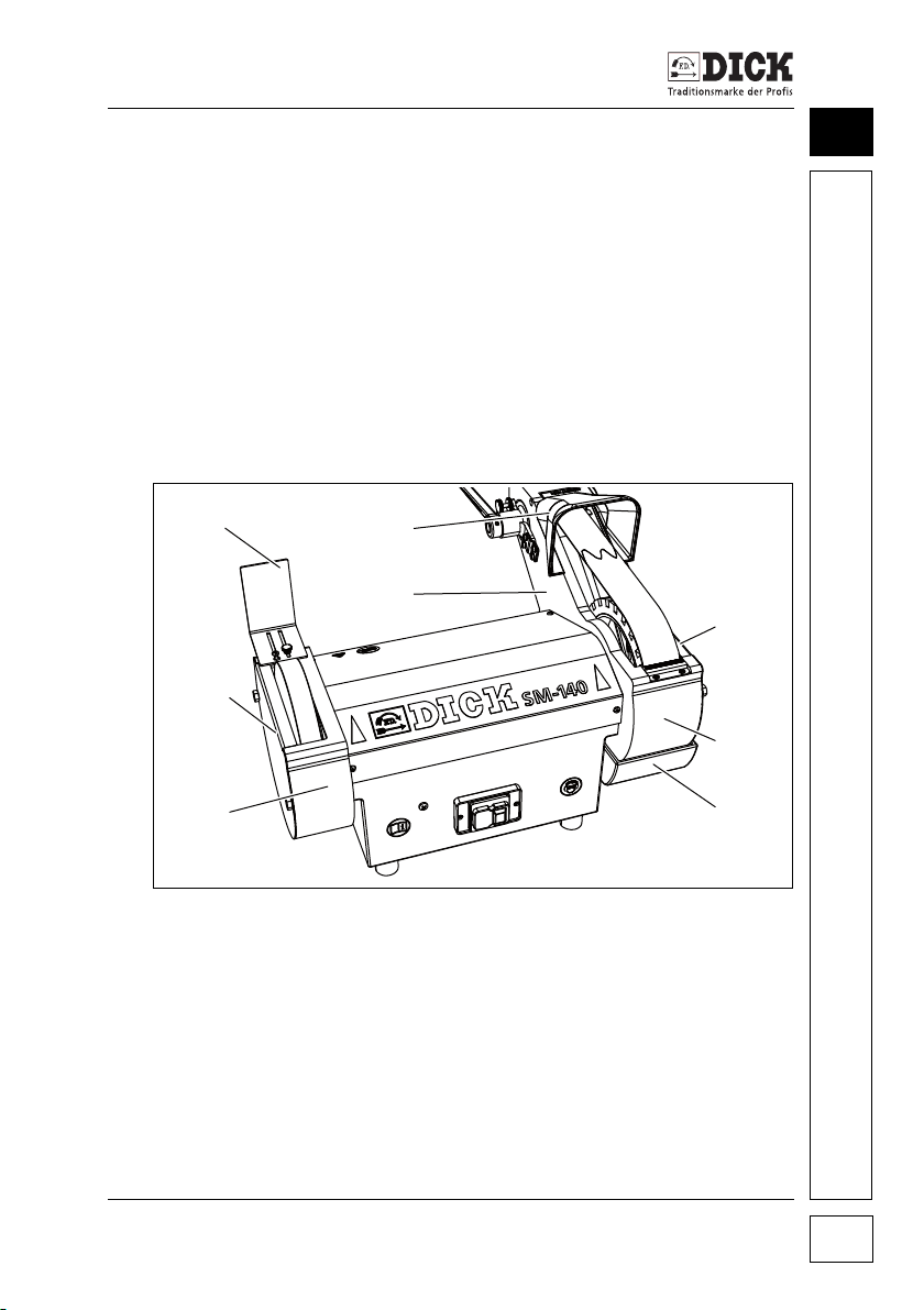
Figure 6.2 – Covering danger zones
[1] Deflection plate
[2] Sprayhood
[3] Left-hand side panel of the grinding arm
[4] Right-hand side panel of the grinding arm
[5] Front cover of the grinding belt
[6] Water tank
[7] Left-hand side panel of the polishing wheel
[8] Cover of the polishing wheel
Belt grinder SM-140 15
Page 16
Putting into operation
1
7
7. Putting into operation
7.1 Installing the belt grinder
Risk of injuries in the event of slipping, falling or tilting belt
grinder
• Install the belt grinder on a stable table or other stand or
substructure, which has sufficient stability to carry the weight
of the belt grinder.
• The stand must not be mobile or fitted with wheels or castors.
• Install the belt grinder on a flat, slip-proof surface so that the
belt grinder does not slip, tilt or otherwise move when used.
Note the ergonomic requirements
• The machine must be installed in such a way that safe
working is possible for a person in an upright position.
• Ensure good lighting is provided at the workplace.
7.2 Assembling the belt grinder
WARNING
CAUTION
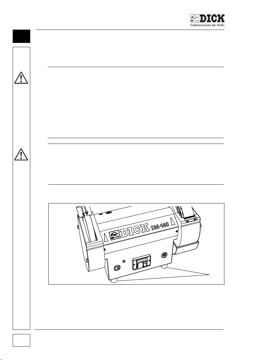
Figure 7.1 – Installation
[1] Machine base
Belt grinder SM-140
16
Page 17
Putting into operation
1
2
3
4
The belt grinder is installed on the machine bases [1] on
a slipproof, clean and flat surface.
7.3 Setting & adjusting the belt grinder
CAUTION
Risk of injuries due to rotating machine parts
• Remove the plug from the socket before carrying out any
adjustment work.
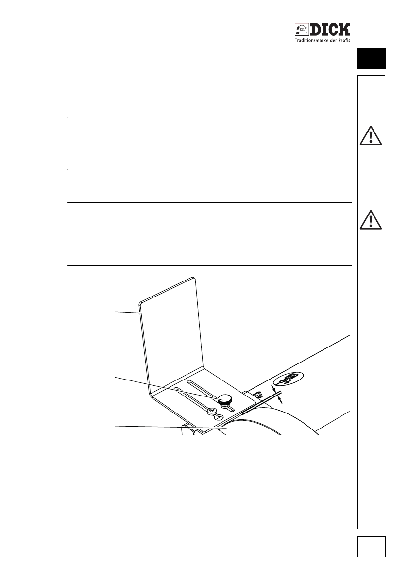
Adjusting the deflector plate
CAUTION
Risk of injuries due to rotating machine parts
• The distance between the deflection plate and polishing
wheel must be checked each time before starting work
using the belt grinder, and if necessary readjusted.
7
Figure 7.2 – Adjusting the deflection plate
[1] Deflection plate
[2] Distance (2 mm maximum)
[3] Polishing wheel
[4] Knurled nut
Belt grinder SM-140 17
Page 18
Putting into operation
5
1
4
2
3
7
The distance [2] between the deflection plate [1] and the polishing
wheel [3] must not exceed 2 mm.
1 Undo the knurled nut [4],
2 Adjust the distance [2],
3 Tighten the knurled nut [4].
7.4 Adjusting the belt alignment and running
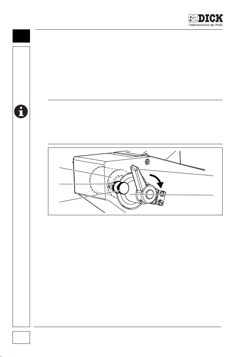
DAMAGE TO THE BELT GRINDER DUE TO SKEW STARTING
A misaligned, skew-running belt damages the housing.
• Before switching on the belt grinder, check the running of the
UP OF THE GRINDING BELT!
grinding belt, to ensure it is straight.
Figure 7.3 – Adjusting device
[1] Deflection pulley
[2] Tensioning lever
[3] Belt tensioner
[4] Knurled adjusting screw
[5] Knurled lock nut
Belt grinder SM-140
18
Page 19
Putting into operation
2
3
1
4
1 Release the clamping lever [2] and undo the knurled lock
nut [5] of the belt tensioner [3].
2 Turn the grinding belt by hand and at the same time check
whether it drifts to the side.
3 If necessary, use the knurled adjusting screw [4] so that the
belt runs in the middle of the deflection pulley [1].
4 Re-tighten the knurled lock nut [5].
5 If necessary, readjust while the motor is running.
7.5 Adjusting and dismantling the water tank
7
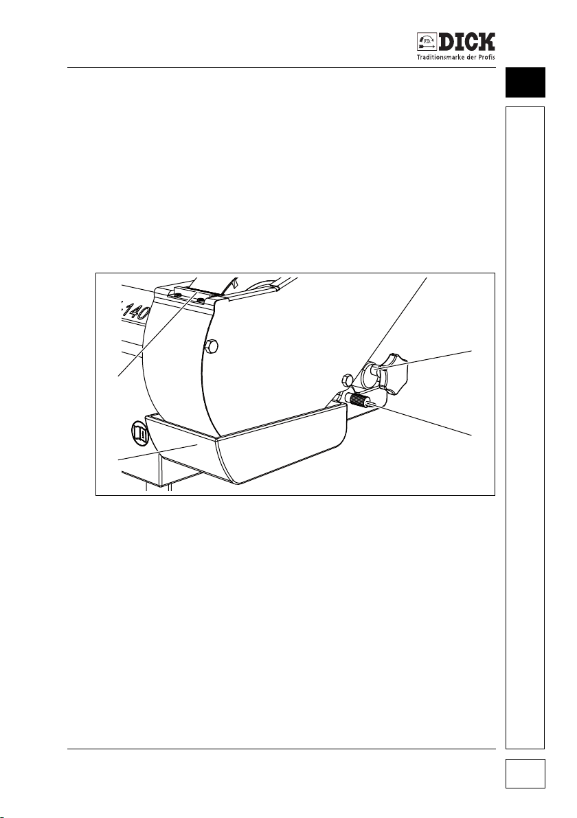
Figure 7.4 – Water tank
[1] Distribution brush
[2] Eccentric
[3] Fixing bolt
[4] Water tank
To avoid overheating of the cutting tools the SM-140 belt grinder
has integrated water cooling. The grinding belt dips into a water
bath and through this movement removes a quantity of water,
which is then distributed over the surface of the grinding belt by
a distributing brush [1].
Belt grinder SM-140 19
Page 20
Putting into operation
1
7
Adjusting the water tank
The quantity of water on the grinding belt is controlled by turning
the eccentric [2].
1 Turn the star handle of the eccentric so that the water tank
2 After using the machine, swing the water tank [4] back
Dismantling the water tank
1 To empty and clean the water tank, pull out the conical fixing
2 Immediately before the next use fill the water tank up to the
7.6 Controls on the belt grinder
swings upwards. The water level should just touch the belt
and therefore wet the grinding belt with water.
downwards.
bolt [3] while at the same time turning it by hand.
marking indicated inside the tank, insert and adjust.
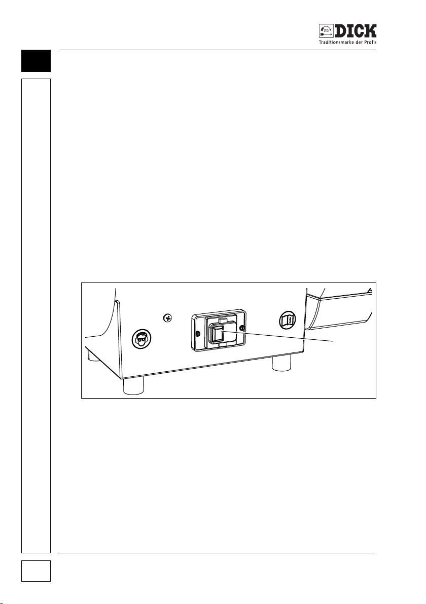
Figure 7.5 – Switches
[1] Switch for switching off (red, 0)
[2] Switch for switching on (green, I)
Belt grinder SM-140
20
Page 21
Putting into operation
7.7 Switching on the belt grinder
WARNING
Risk of injury due to damaged or incorrectly mounted
machine parts
Using the belt grinder with damaged electric parts or power
cables can cause injuries due to electric shocks or malfunctions.
Damaged grinding belts can be partly spun off the machine.
• Missing or damaged covers expose rotating parts and can
cause injuries due to crushing and drawing in. Check the belt
grinder for damage before each use, in particular:
- the grinding belt,
- the polishing wheel,
- the power cable,
- correct assembly and covering function of all covers and
the housing,
- the function of the switches.
• Replace damaged parts before using the belt grinder again.
CAUTION
Risk of injuries due to poor health of the operator
Lack of concentration, over-tiredness, illness, drunkenness or leg
or arm disabilities as well as mental disabilities cause a high risk
of injuries.
7
• People who work at the belt grinder must be healthy and
capable of concentrating.
• Before starting work at the belt grinder, ensure you are in
a stable position in which you can maintain your balance
without any effort.
• When grinding and polishing, do not look away from the belt
grinder and workpiece.
Belt grinder SM-140 21
Page 22
Putting into operation
7
Risk of injuries on touching the belt grinder
Touching the grinding belt or polishing wheel while the belt grinder
is switched on causes injuries.
• Do not touch any abrasives while the belt grinder is
• Do not use any objects to brake rotating abrasives.
• The switched on belt grinder must be inaccessible to persons
• Before leaving the work area, switch off the belt grinder and
Rotating machine parts can catch unsuitable clothing or long hair.
Abrasive particles spun off the machine or loud machine noises
can damage eyes and ears.
Sharp and hot workpieces can cause injuries to hands.
Rotating abrasives can pull off pieces of clothing.
CAUTION
switched on.
not working at the belt grinder, especially to children.
remove the mains plug from the socket.
WEAR SUITABLE CLOTHING
• Ensure good lighting is available,
• wear tight-fitting clothing,
• do not wear jewellery,
• wear a hair net on long hair,
• wear safety glasses or goggles,
• wear hearing protection,
• wear suitable protective gloves,
• do not touch rotating machine parts with parts of the body
covered with fabric.
Belt grinder SM-140
22
Page 23
Putting into operation
Switch on the belt grinder as follows:
1 Insert the plug into the socket.
2 Check the belt running (see "Setting & adjusting the belt
grinder" on page 17).
3 Adjust the water level (see "Adjusting the water tank"
on page 20).
4 Press the green button (switch) at the switch.
5 Check the direction of rotation when starting up the belt grinder.
- The direction of rotation is given by arrows on the covers.
7.8 Switching off the belt grinder
1 Press the red switch (Switches, Item [1]).
2 Wait until the grinding belt and the polishing wheel stop.
3 After using the machine, swing the water tank back down-
wards.
WARNING
Risk of electric shock
If the plug is removed from the socket by pulling the power cable,
the connection between the plug and cable can be damaged and
is therefore a substantial source of danger.
• When disconnecting the power connection, hold onto the
plug and pull it out of the socket.
7
4 Pull the mains plug out of the socket.
5 Cleaning the belt grinder.
6 Empty and clean the water tank (see "Dismantling the water
tank" on page 20).
Belt grinder SM-140 23
Page 24
Putting into operation
7
Risk of injuries after thoughtless switching on of the belt
grinder
If the belt grinder is left unattended after grinding work, there is
a risk of the belt grinder being switched on by unauthorised or
thoughtless persons.
• After carrying out grinding work, never leave the belt grinder
• Store the belt grinder in a safe place, to which unauthorised
WARNING
unsupervised unless the mains plug has been disconnected.
persons do not have access.
Belt grinder SM-140
24
Page 25
Machining workpieces
1
2
8. Machining workpieces
8.1 Grinding workpieces
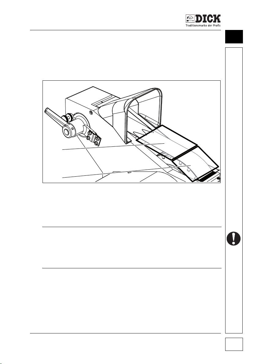
Grinding zones
Figure 8.1 – Grinding zones
[1] Grinding on the free belt for convex grinding
[2] Grinding with underlay on the rubber-contact wheel
8
NOTE
Dirty knives can irreparably damage the grinding belt and
polishing wheel. The surfaces can heat with long-term use.
• Only machine clean knives.
• Switch off the belt grinder after 30 minutes at the latest.
Belt grinder SM-140 25
Page 26
Machining workpieces
1
2
3
4
5
8
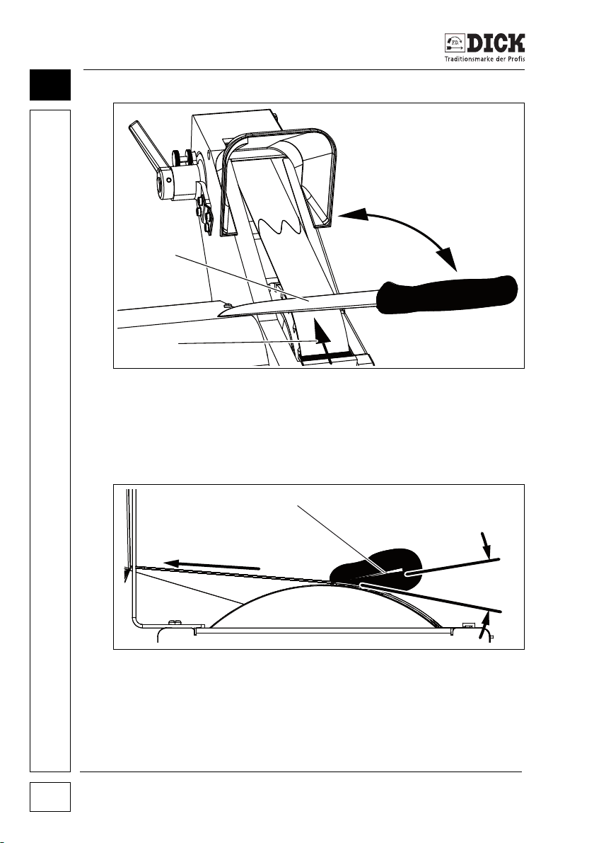
Figure 8.2 – Grinding (sharpening) knives
[1] Knife edge
[2] Direction of rotation of the abrasive
[3] Knife positioned at right-angles to the grinding belt
Figure 8.2 – Grinding (sharpening) knives
[4] Knife blade
[5] Positioning angle for the knife blade (15°)
Belt grinder SM-140
26
Page 27
Machining workpieces
WARNING
Risk of injuries
The blade can cut into the grinding belt and be torn out of
your hand.
• Never grind against the cutting edge.
1 Position the knife at the belt grinder so that the knife
blade [1] points in the direction of rotation of the grinding
belt [2] or the polishing wheel [2].
2 Align the knife blade horizontally so that it is positioned
roughly perpendicular [3] to the grinding belt.
3 Position the knife blade [4] on the grinding belt at an angle
of approx. 15 degrees [5].
4 When grinding, grind the sides of the blade alternately,
until a burr has formed over the entire area.
NOTE
Workpieces heat during grinding
An over-heated blade can anneal (loss of hardness) and stress
cracks can form in it.
• Always wet grind cutting tools.
8
NOTE
If the blade has become thicker as a result of frequent grinding,
the blade thickness can be reduced again by grinding the
flat sides.
Belt grinder SM-140 27
Page 28
Machining workpieces
1
2
8
8.2 Polishing workpieces
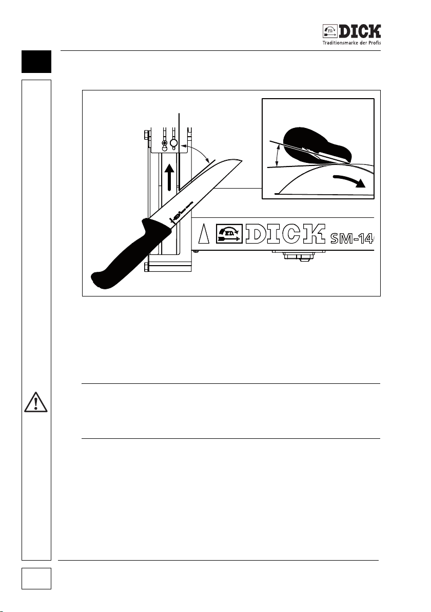
Figure 8.3 – Polishing knives
[1] Positioning angle slanted relative to the running direction
(forming an angle of approx. 30° – 60°)
[2] Positioning angle relative to the polishing wheel (approx. 20°)
Risk of injuries
The blade can cut into the polishing wheel and be torn out of your hand.
• Never polish against the cutting edge.
1 Hold the polishing paste against the polishing wheel while it
2 Position the knife slanted relative to the running direction,
3 Position the knife at the polishing wheel at a more obtuse
4 Hone the knife until the burr has been completely removed
5 Polish both sides of the blade alternately.
Belt grinder SM-140
28
WARNING
is running,
angle than for grinding,
and the surface has the required polish.
Page 29
Servicing and maintenance
1
2
3
4
9. Servicing and maintenance
WARNING
Risk of injuries due to unauthorised or thoughtless switching
on or wrong spare parts
• Always disconnect the mains plug before carrying out any
maintenance or repair work on the belt grinder.
• Only use original spare parts from Friedr. Dick GmbH & Co. KG.
WARNING
Risk of injuries due to improper repair work
• Any repair work on electric components may only be carried
out by qualified electricians.
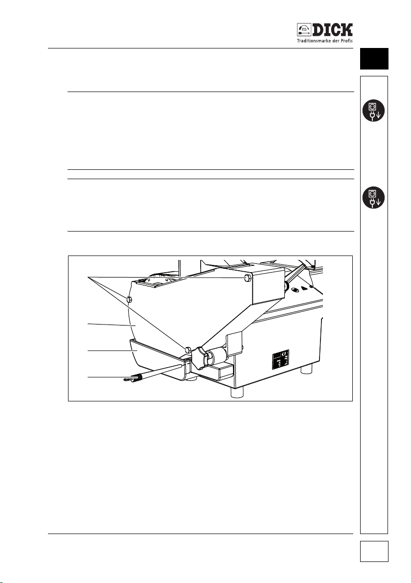
9.1 Cleaning the belt grinder
9
Figure 9.1 – Cleaning the belt grinder
[1] Fastening screws
[2] Right-hand side panel
[3] Water tank
[4] Fixing bolt
The belt grinder must be cleaned after each work session.
Belt grinder SM-140 29
Page 30
Servicing and maintenance
1
2
9
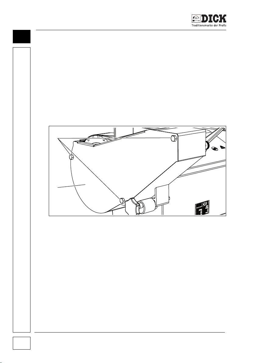
1 Remove and clean the water tank,
2 Undo the fastening screws and remove covers,
3 Remove residual abraded material from the machine,
e.g. using a brush.
4 Re-attach covers and screw tight.
9.2 Changing the grinding belt
Change the grinding belt if it has become blunt. (Interval:
approx. 100 – 150 grinding operations).
Replace the polishing wheel as follows:
Figure 9.2 – Grinding arm
[1] Fastening screws
[2] Right-hand side panel
Belt grinder SM-140
30
Page 31
Servicing and maintenance
3
4
5
67
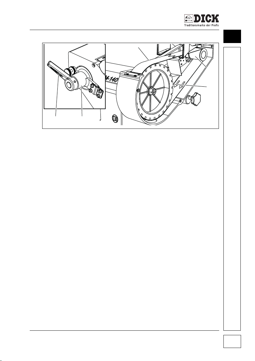
Figure 9.2 – Grinding arm
[3] Grinding belt
[4] Deflection pulley
[5] Direction of rotation indication on the grinding belt
[6] Belt tensioner
[7] Tensioning lever
1 Remove the water tank (see "Cleaning the belt grinder"
on page 29),
2 Undo the fastening screws [1] of the right-hand side
panel [2],
3 Remove the side panel [2],
4 Undo the belt tensioner [6] with clamping lever [7] and turn
anti-clockwise to relax (see "Adjusting the belt alignment
and running" on page 18),
5 Pull the deflection pulley [4] inwards and remove the grin-
ding belt [3],
6 Put on the new grinding belt so that the direction of rotation
indicated on the grinding belt [5] matches the direction of
rotation of the belt grinder,
7 Install the individual parts in the reverse order.
8 Check the belt running and if necessary adjust
(see "Setting & adjusting the belt grinder" on page 17).
9
Belt grinder SM-140 31
Page 32
Servicing and maintenance
12345
9
9.3 Changing the polishing wheel
The polishing wheel must be replaced if the distance between the
deflection plate and polishing wheel can no longer be adjusted
(see "Adjusting the deflector plate" on page 17).
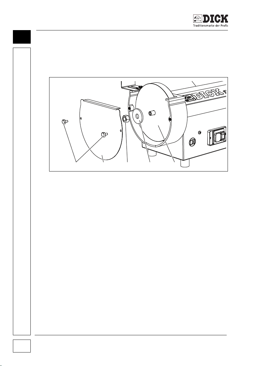
Figure 9.3 – Polishing wheel
Replace the polishing wheel as follows:
[1] Fastening screws for cover
[2] Cover
[3] Fastening nut
[4] Flange cover
[5] Polishing wheel
1 Undo the fastening screws [1] of the cover [2],
2 Remove the cover [2],
3 Undo the fastening nuts [3] of the flange cover [4]
(right-hand thread),
4 Remove the flange cover [4],
5 Replace the polishing wheel [5].
6 Install the individual parts in the reverse order.
Belt grinder SM-140
32
Page 33

Servicing and maintenance
After finishing all repairs and servicing work, check that all
dismantled parts have been completely and correctly installed,
especially the covers.
After changing a trial run must be carried out for 1 minute.
In case of unusual behaviour, switch off the machine and
correct the cause.
9
Belt grinder SM-140 33
Page 34
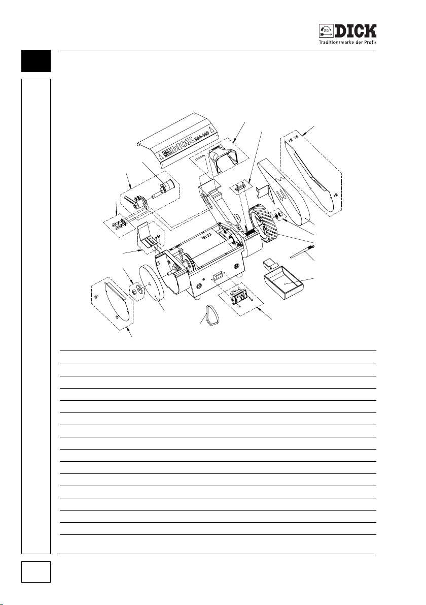
10
9 8249 3973
9 8249 3979
9 8249 3980
9 8249 3938
9 8249 3902
9 8249 3854
9 8249 3981
9 8249 3875
9 8249 3920
9 8079 3648
9 8249 3977
9 8249 3972
9 8249 3975
9 8249 3885
9 8249 3974
9 8079 3659
9 8249 3976
Spare Parts
10. Spare Parts
10.1 Spare parts drawing
34
Order no. Quantity Name Dimensions
9 8079 3648 1 no. Polishing wheel ø200 x 25 x ø16, Part 3648
9 8219 0333 1 no. Polishing paste 300g
9 8079 3659 1 set Switch, complete 1~230V 50/60Hz
9 8249 3852 1 set Operating instructions
9 8249 3854 1 no. Water tank SM-140 mod13
9 8249 3875 1 no. Contact washer ø200 x 50
9 8249 3885 1 assembly Belt tension, complete SM-140 mod13
9 8249 3902 1 no. Fixing bolt SM-140 mod13
9 8249 3920 1 no. V-belt Z 450 GB
9 8249 3938 10 no. Set of grinding belts P120 1000 x 50
9 8249 3972 1 set Cover, left, complete SM-140 mod13
9 8249 3973 1 set Cover, right, complete SM-140 mod13
9 8249 3974 1 assembly Deflection pulley, complete SM-140 mod13
9 8249 3975 1 set Spring set SM-140 mod13
9 8249 3977 1 set Flange set, left SM-140 mod13
Belt grinder SM-140
SM-140 – 230V D/GB/F/I/E/RUS
Page 35
Spare Parts
Order no. Quantity Name Dimensions
9 8249 3978 1 set Switch, complete 3~400V 50/60Hz
9 8249 3979 1 set Sprayhood SM-140 mod13
9 8249 3980 1 set Brush set SM-140 mod13
9 8249 3981 1 set Flange set, right SM-140 mod13
9 8249 3982 1 no. Capacitor 10 µF
10.2 Ordering spare parts
CAUTION
Risk of accidents due to wrong spare parts
Using parts which are not matched to the belt grinder constitutes
an unratable risk.
• Use DICK original spare parts only.
Please order spare parts as follows:
Choose the parts to be replaced from the spare parts drawing,
with order number and name.
Your spare part order must include the following details:
10
1 Required quantities
2 Order number
3 Name
4 Machine type, machine article number, serial number,
year of manufacture (see type plate on back of machine).
Please send your order for spare parts to your specialist dealer or to:
Friedr. Dick GmbH & Co. KG
Postfach 1173
73777 Deizisau
GERMANY
Tel.: (49) (0)7153 817-0
Fax: (+49) (0)7153 817-218 or -219
E-mail: [email protected]
Web: www.dick.de
Belt grinder SM-140 35
Page 36

11
EC Declaration of Conformity
11. EC Declaration of Conformity
Manufacturer
Friedr. Dick GmbH & Co. KG
Esslinger Str. 4-10
73779 Deizisau
GERMANY
We herewith declare, in sole responsibility, that the following product:
Belt grinder – Type SM-140
with the serial number given on the belt grinder's type plate,
conforms to the following EC Directives:
EC Machinery Directive (2006/42/EC),
EC EMC Directive (2004/108/EC).
European standards applied:
• EN ISO 12100:2010,
• EN 60204-1:2006,
• EN 61029-1:2009+A11:2010,
• EN 61029-2-4:2003+A1:2003+AB:2010,
• EN 61000-3-2:2006+A1:2009+A2:2009,
• EN 61000-3-3:2008,
• EN 55014-1:2006+A1:2009+A2:2011,
• EN 55014-2:1997+A1:2001+A2:2008+AC:1997.
The authorised representative responsible for compiling the
technical documentation at Friedr. Dick GmbH & Co. KG is
Dipl. Ing. Horst Löhnert.
Belt grinder SM-140
36
 Loading...