


Wall saw system FZ-2S
Index 000
Operating instructions Spare parts list

0.1Introduction
Dear customer
You have decided to buy a HYDROSTRESS system. You acquired a highly sophisticated and reliable state-of-the-art unit..
Due to our special efforts in the field of quality assurance, the wall saw system FZ-2S is a further Swiss, top-of-the-range product:
•high sawing performance
•reliable operation
•high mobility
•easy handling
•low maintenance costs
The exclusive use of genuine HYDROSTRESS spare parts ensures quality and interchangeability.
In the case of neglected or inappropriate maintenance, we refuse to accept any warranty commitment as specified in our terms of delivery.
Any repair work is to be carried out by trained personnel only.
Should you need to know more details concerning your HYDROSTRESS system in order to keep it in perfect condition, please contact our after-sales service for further information.
We would be pleased to hear that working with your HYDROSTRESS system was without any difficulties and troublefree.
HYDROSTRESS AG
The Management
Copyright © HYDROSTRESS AG, 1998
+<'52675(66 $* :LW]EHUJVWUDVVH
&+ 3IlIILNRQ =+ 6ZLW]HUODQG
7HOHIRQ
7HOHID[
)= 6
0.2Validity of this manual
This manual is only valid for the following system:
Wall saw system FZ-2S Index 000
0.3Technical standards
This manual has been written in accordance with the CE-directives and the relevant technical standards.
0.4Delimitation of system
Also described in this manual are the use of both blade guard and tracks.
Operation of power units
Instructions for the operation of power units are mentioned in this manual for the safety of the operating personnel. In order to operate any power unit safely, its operating instructions have to be followed as well.
Page 2 |
FZ_29811 |

)= 6
0.5Table of contents
0.1 |
Introduction |
2 |
0.2 |
Validity of this manual |
2 |
0.3 |
Technical standards |
2 |
0.4 |
Delimitation of system |
2 |
0.5 |
Table of contents |
3 |
1 |
Safety instructions |
4 |
1.1 |
Fundamentals |
4 |
1.2 |
Before machining |
7 |
1.3 |
During sawing |
8 |
1.4 |
After machining |
8 |
2 |
Technical data |
9 |
2.1 |
Dimensions (Text) |
9 |
2.2 |
Dimensions (Figure) |
9 |
3 |
Range of application |
10 |
3.1 |
Connectable units |
10 |
3.2 |
Possible applications |
10 |
4 |
Design and function |
11 |
4.1 |
Design of wall saw system |
11 |
4.2 |
Safety devices |
11 |
4.3 |
Track system |
11 |
4.4 |
Design wall saw head |
11 |
4.5 |
Function |
12 |
4.6 |
Operating elements and connections |
14 |
5 |
Set-up |
16 |
5.1 |
Initial set-up |
16 |
5.2 |
Preparatory operations |
16 |
5.3 |
Choosing the saw blade |
17 |
5.4 |
Choosing the saw motor |
20 |
5.5 |
Changing the saw motor |
22 |
5.6 |
Fixing the tracks on concrete |
23 |
5.7 |
Mounting the wall saw head |
24 |
5.8 |
Fasten the adjusting grips |
24 |
5.9 |
Release of the carriage guides |
25 |
5.10 |
Mounting blade and blade guard or flush |
|
|
cutting flange |
25 |
5.11 |
Connecting the power unit |
26 |
6 |
Sawing |
28 |
6.1 |
Before sawing |
28 |
6.2 |
The first cut |
28 |
6.3 |
After the first cut |
29 |
6.4 |
End of machining |
30 |
7 |
Troubleshooting |
31 |
8 |
Maintenance |
33 |
8.1 |
Maintenance table |
33 |
8.2 |
Change oil swivelling arm |
34 |
8.3 |
Replacing guiding devices |
35 |
8.4 |
Replacing feed motor |
35 |
8.5 |
Replace swivelling motor |
35 |
8.6 |
Refilling lubricant |
36 |
9 |
Repairing |
37 |
10 |
Transport, placing out of service, |
|
|
storing, disposal |
38 |
10.1 |
Transport |
38 |
10.2 |
Placing out of service and storage |
38 |
10.3 |
Disposal |
38 |
11 |
Accessories |
39 |
12 |
Spare parts list |
40 |
12.1 |
Order indications |
40 |
12.2 |
Table of contents (Spare parts) |
41 |
FZ_29811 |
Page 3 |

6DIHW\ LQVWUXFWLRQV |
)= 6 |
1 Safety instructions
1.1Fundamentals
Qualification of operating personnel
Machining concrete and stone is neither simple nor without danger. High material assets on the job site, the machine itself and the safety of people are at stake.
The personnel has to be trained by experienced experts.
HYDROSTRESS can support you in your training efforts.
Read the manual and inform your work-fellows!
This manual contains important information in order to operate the machine safely and efficiently.
The owner of the machine must make sure that the instructions in this manual are followed by any person having to do with the machine, its equipment or its auxiliary material.
The manual must be accessible on the job site at any time.
Hazards on the building-site
The machine/plant has been built in accordance with state-of-the-art standards and the recognized safety rules. Nevertheless, its use may constitute a risk to life and limb of the user or of third parties, or cause damage to the machine and to other material property.
Pay attention to the special working conditions on the building-site. Protect yourself and others within your responsability against the manifold hazards!
Page 4 |
FZ_29811 |
)= 6
Recognize warnings!
Pay attention to the following words, their characteristics and their meaning:
Danger:
Orders or prohibitions designed to prevent injury
Attention:
Information designed to prevent damage
Important:
Information on how to use the machine most efficiently.
Noise (noise level)
Depending on the working environment the machine can cause excessive noise.
The noise can harm the hearing of operating personnel and of other people nearby quickly.
Ear protectors must therefore always be worn during machining.
Safety clothing
Safety clothing must always be worn when machining concrete or stone in order to beware of the following hazards:
6DIHW\ LQVWUXFWLRQV
FZ_29811 |
Page 5 |

6DIHW\ LQVWUXFWLRQV |
)= 6 |
Hazard |
Safety clothing |
|
|
falling parts: |
helmet, hard-toed |
|
boot |
moving, |
|
sharp-edged parts: |
gloves |
flying sparks and |
safety glasses |
pieces: |
|
slipping: |
antislipping shoes |
noise: |
ear protectors |
contamination of |
|
airways: |
mask |
Materias to be machined
Only the following materials are to be machined by HYDROSTRESS-equipment:
• Concrete and stone
Other materials are not to be machined. Especially avoid machining:
– :RRG SODVWLF RU JODVV
Cutouts and drilling cores
These pieces can be very heavy.
Example:
A cube of concrete measuring 0.5 by 0.5 by 0.5 meters weighs about 300 kg. A drilling core with a diameter of 30 cm and a lenght of 1 meter weighs about 180 kg.
Make sure that these pieces can not fall or tip over and cordon off the hazardous area!
Safety devices
Never run the machine without correctly mounted safety devices (see "safety devices" in this manual)!
Power units and accessories
Use the machine exclusively together with the recommended power units and accessories (see "connectable units" and "accessories" in this manual).
Local safety regulations
Pay attention to the safety regulations of your local branch associations!
Page 6 |
FZ_29811 |

)= 6
1.2Before machining
Emergency stop
Make sure that you know how to stop the machine immediately (see "Emergency stop")!
First aid
Find out where to get help in case of an accident!
Supply lines
Make sure that all supply lines are turned off in your machining area! Find out whether such lines may be cut through!
Reinforcement
Find out whether the reinforcement in your machining area may be cut.
Manage your work place
Manage your work place well! This helps prevent accidents effectively.
Lighting of the work place
Ensure sufficient lighting of your workplace.
Safe areas for the operating personnel and other people
The machine is designed to be operated by one single person.
During machining other people are to stay whithin safe distance.
The controls of the power unit or the remote control must be easily reachable during machining.
An emergency stop must be possible at any time (see "Emergency stop").
6DIHW\ LQVWUXFWLRQV
FZ_29811 |
Page 7 |

6DIHW\ LQVWUXFWLRQV |
)= 6 |
1.3During sawing
Use only the screws specified for this purpose and meeting the prescribed length and quality requirements!
Never use saw blades with cracks! Cracked saw blades can brake during sawing and endanger people.
Power feed
Machines with power feed are not automatic machines. They have to be observed during machining. An emergency stop must be feasable at any time.
Rotating and moving parts
To prevent of being caught by rotating or moving parts wear tight-fitting clothes and a hearnet in the case of long hear!
1.4After machining
Electric power units
Unplug the mains right after machining in order to prevent unintentional switching-on of the power unit!
Removing cutouts and drilling cores
Use appropriate lifting gear in order to prevent injuries!
Page 8 |
FZ_29811 |

)= 6 |
7HFKQLFDO GDWD |
2 Technical data
2.1Dimensions (Text)
Total weight
NJ |
ZDOO VDZ ZLWKRXW VDZ PRWRU |
NJ |
K\GUDXOLF PRWRU VDZ PRWRU |
NJ |
EODGH JXDUG LQ SLHFHV |
NJ |
WUDFNV SHU PHWHU |
Blade drive |
|
+\GUDXOLF PRWRU |
8 PLQ |
6SHHG UDWLR |
|
:RUNLQJ SUHVVXUH |
PD[ EDU |
Power feed |
|
+\GUDXOLF PRWRU |
|
:RUNLQJ SUHVVXUH |
PD[ EDU |
)HHG IRUFH |
PD[ N1 |
7UDFWLRQ |
JHDUZKHHO RQ WUDFN |
Swivelling |
|
+\GUDXOLF PRWRU |
|
:RUNLQJ SUHVVXUH |
PD[ EDU |
6ZLYHOOLQJ UDQJH |
R |
Guidance |
|
DGMXVWDEOH DQG H[FKDQJHDEOH JXLGLQJ GHYLFH
Tracks |
|
/HQJWK |
FP |
|
FP |
|
FP |
|
FP |
|
FP |
+ROH VSDFLQJ |
FP |
2.2Dimensions (Figure)
Fig. masse.tif
FZ_29811 |
Page 9 |
5DQJH RI DSSOLFDWLRQ |
)= 6 |
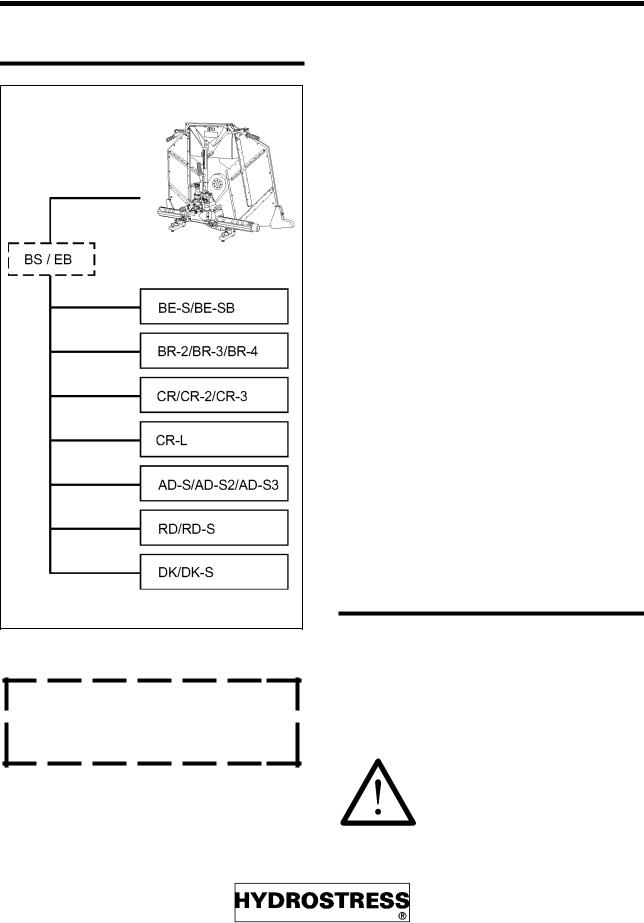
3 Range of application
3.1 Connectable units |
Particularities of the different power units |
Fig. fz1-1z.tif
BE-S oder BE-SB must only be operated with the additional use of a hose shut-off valve or a motor unit with a shut-off valve.
The output of the various units differs according to type. In order to obtain optimum cut performance, the appropriate saw motor is to be selected according to the unit employed and the type of application (see "choosing the saw motor")
&5 / |
OHYHO |
%5 %5 %5 |
OHYHOV |
&5 &5 |
OHYHOV |
&5 $' 6 5' |
OHYHOV |
'. '. 6 |
|
%( 6 %( 6% |
SRZHU IHHG ZKHQ XVLQJ |
|
SRZHU IHHG PRGXOH |
5HPRWH FRQWURO %6 |
ORQJ KRVHV DYDLODEOH |
|
P |
5HPRWH FRQWURO (% |
DWWDFKDEOH WR HDFK |
|
GHYLFH |
3.2Possible applications
–)OXVK FXWWLQJ
–$QJXODU FXWWLQJ
–&XWWLQJ RI MRLQWV
–:LUH VDZLQJ ZLWK H[WHQVLRQ NLW IURP +<'52675(66
The machine is not intended for any other use. Such use can be especially dangerous.
Page 10 |
FZ_29811 |
)= 6 |
'HVLJQ DQG IXQFWLRQ |
4 Design and function
4.1Design of wall saw system
The wall saw system FZ consists of:
–:DOO VDZ KHDG
–%ODGH JXDUG
–7UDFNV
Wall saw head
The wall saw head incorporates all hydraulic und mechanic components necessary for:
–%ODGH GULYH
–3RZHU IHHG
–6ZLYHOOLQJ Q
4.2Safety devices
Blade guard in 3 parts
–IROORZV WKH VZLYHO DUP
–UHPRYDEOH ODWHUDO SDUWV
–RU PP
–PDWHULDOV SODVWLF DQG DOXPLQXP
–QR IOXVK FXWV SRVVLEOH
Blade guard in 2 parts
–PP
–PDWHULDO DOXPLQXP
–DOVR IOXVK FXWV SRVVLEOH
4.3Track system
–IL[HG WR WKH XQGHUJURXQG VXUIDFH E\ PHDQV RI WKH WHQVLRQLQJ EORFN DQG WKH GRZHO EROW
4.4Design wall saw head
Fig. aufbau.tif
6DZ PRWRU
6ZLYHOOLQJ PRWRU
%ODGH JXDUG KROGHU
6ZLYHOOLQJ DUP
7RRWKHG EHOW
7RRWKHG EHOW ER[
:DWHU FRXSOLQJ
2YHUORDG SURWHFWLRQ
+DQGOH
&KDVVLV
7UDFN
7UDFN EDVH
7HQVLRQLQJ EORFN
< +DQGOH
)HHG +DQGOH
)HHG *HDU
FZ_29811 |
Page 11 |
'HVLJQ DQG IXQFWLRQ |
)= 6 |
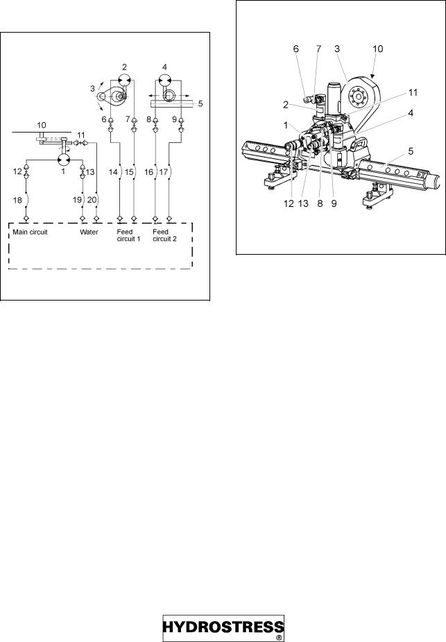
4.5 Function |
Function (Figure) |
|
|
Hydraulic scheme
Fig. fz2-2ae.tif
|
6DZ PRWRU |
|
|
6ZLYHOOLQJ PRWRU |
|
|
6ZLYHOOLQJ DUP |
|
|
)HHG PRWRU |
|
|
7UDFN |
|
|
&RXSOLQJ |
VZLYHOOLQJ |
|
1LSSOH |
VZLYHOOLQJ |
|
&RXSOLQJ |
IHHG |
|
1LSSOH |
IHHG |
|
:DWHU RXWOHW |
DW VDZ EODGH |
|
&RXSOLQJ |
:DVVHU |
|
&RXSOLQJ |
VDZ PRWRU |
|
1LSSOH |
VDZ PRWRU |
|
+\GUDXOLF KRVH |
|
|
:DWHU KRVH |
|
Fig. funktion.tif
|
6DZ PRWRU |
|
|
6ZLYHOOLQJ PRWRU |
|
|
6ZLYHOOLQJ DUP |
|
|
)HHG PRWRU |
|
|
7UDFN |
|
|
&RXSOLQJ |
VZLYHOOLQJ |
|
1LSSOH |
VZLYHOOLQJ |
|
&RXSOLQJ |
IHHG |
|
1LSSOH |
IHHG |
|
:DWHU RXWOHW |
DW VDZ EODGH |
|
&RXSOLQJ |
:DVVHU |
|
&RXSOLQJ |
VDZ PRWRU |
|
1LSSOH |
VDZ PRWRU |
|
+\GUDXOLF KRVH |
|
|
:DWHU KRVH |
|
Page 12 |
FZ_29811 |

)= 6 |
|
|
'HVLJQ DQG IXQFWLRQ |
|
Function (table) |
|
|
|
|
|
|
|
|
|
From where ... |
WKURXJK ZKDW |
... to where? |
5HPDUNV |
|
|
|
|
|
|
|
Blade drive |
|
|
|
Main circuit |
+RVHV |
Saw motor (1) |
6HQVH RI URWDWLRQ LV IL[HG |
|
Saw motor (1) |
7RRWKHG EHOW |
Saw blade |
*HDU UDWLR |
|
|
|
|
|
|
|
Power feed |
|
|
|
Feed circuit |
+RVHV |
Feed motor (4) |
&RQWURO RI VHQVH RI PRWLRQ DQG VSHHG |
|
|
|
|
DW WKH SRZHU XQLW |
|
Feed motor |
:RUP GULYH |
Gearwheel |
*HDUZKHHO HQJDJHV LQ WUDFN |
|
|
|
|
|
|
|
Swivel arm drive |
|
|
|
Feed circuit |
+RVHV |
Swivelling |
&RQWURO RI VHQVH RI URWDWLRQ DQG |
|
|
|
motor (2) |
||
|
|
VSHHG DW WKH SRZHU XQLW |
||
Swivelling motor (2) |
*HDUZKHHO |
Swivelling arm |
R |
|
|
|
|
|
|
|
Water |
|
|
|
Power unit |
+RVHV |
Coupling at the |
&RQWURO WKHZDWHU VXSSO\ DW WKH SRZHU |
|
|
|
wall saw head |
||
|
|
XQLW |
||
Coupling at the wall |
:DWHU SLSH DW WKH |
Swivelling arm |
:DWHU VXSSO\ DW FHQWUH RI IODQJH |
|
saw head |
VZLYHOOLQJ DUP |
|
|
|
|
|
|
|
FZ_29811 |
Page 13 |

'HVLJQ DQG IXQFWLRQ |
)= 6 |
4.6Operating elements and connections
Fig. bedienel.tif
Page 14 |
FZ_29811 |
)= 6 |
'HVLJQ DQG IXQFWLRQ |
Position |
Designation |
Function |
in figure |
|
|
1 |
Bolt for blade guard |
0RXQWLQJ WKH EODGH JXDUG |
2 |
Water connection |
&RQQHFWLQJ WKH ZDWHU KRVH |
3 |
Tensioning block |
)L[LQJ WKH WUDFN RQ FRQFUHWH |
4 |
Adjusting screws |
$GMXVWLQJ WUDFN LQ KLJKW DQG DOLJQHPHQW |
5 |
Adjusting grip |
$GMXVW SOD\ EHWZHHQ ZDOO VDZ KHDG DQG WUDFN |
6 |
Nipple of feed motor |
,QSXW RI IHHG FLUFXLW WR WKH IHHG PRWRU |
7 |
Coupling of feed motor |
2XWSXW RI IHHG PRWRU WR WKH IHHG FLUFXLW |
8 |
Nipple of saw motor |
,QSXW RI WKH PDLQ FLUFXLW WR WKH VDZ PRWRU |
9 |
Nipple of saw motor |
2XWSXW RI WKH VDZ PRWRU WR WKH PDLQ FLUFXLW |
10 |
Cpl. of swivelling motor |
,QSXW RI WKH IHHG FLUFXLW WR WKH VZLYHOOLQJ PRWRU |
11 |
Nipple of swivelling motor |
2XWSXW RI WKH VZLYHOOLQJ PRWRU WR WKH IHHG FLUFXLW |
12 |
Clamping device |
/RFNLQJ WKH ODWHUDO SDUWV RI WKH EODGH JXDUG |
13 |
Clamping device |
5HPRYLQJ WKH EODGH JXDUG |
14 |
Splash guard |
$GMXVWDEOH |
|
|
|
Emergency-Stop
The wall saw system can only be halted quickly by the controls of the power unit. Pay attention to the recommended emergency-stop procedures in the corresponding manual.
FZ_29811 |
Page 15 |

6HW XS |
)= 6 |
5 Set-up
5.1Initial set-up
The wall saw system is delivered ready for setup. All instructions in this chapter are equally valid at the initial set-up.
5.2Preparatory operations
Always proceed as follows:
•Settle fundamental conditions
•Secure the job site
•Determine both position and sequence of the cuts
•Choose the saw blade first and then the saw motor
•Carry out visual inspections and maintenance works
Prior to putting the system into operation, the following steps are always to be observed:
Position of supply lines
Inform yourself about the position of supply lines in walls and ceilings.
Water
Where does the flushing water of the wall saw system drain off? Take appropriate precautions, if necessary.
Secure the job site
Secure the operating area of the wall saw system. No access to unauthorized persons! When cutting into walls, pay attention the other side of the wall! Secure this area too!
Secure cutouts
Secure the cutouts of walls and especially of ceilings by appropriate means, e.g. by a crane, supports etc. Consider the weight of concrete! (1m3 weighs about 2,6 t)
Position of cuts
Inform yourself about the concrete to be cut.
–:KHUH LV WKH UHLQIRUFHPHQW"
–,V WKH FRQFUHWH KHDYLO\ RU OLJKWO\ UHLQIRUFHG"
–,V LW VXLWDEOH IRU GRZHO IL[LQJ"
Determine both the position and the sequence of the cuts prior to starting operation. In case of a door cutout, e.g. first carry out the cut at the bottom, then the lateral cuts, and finally the cut on top.
If possible, cut in perpendicular direction to the reinforcement.
Non-observance of the cutting sequence indicated may lead to blocking the blade or to damages to the system.
Length of tracks
Determine the track length for the cut to be carried out. Allow for sufficient excess length for the wall saw head.
Page 16 |
FZ_29811 |

)= 6 |
6HW XS |
5.3Choosing the saw blade
Select the saw blade with the required diameter with regard to the requirements both of cut and of technical conditions.
Which saw blades are to be used?
outer Ø: |
450 - 2200 mm |
inner Ø: |
60 H7 mm |
Fastening: |
Blade cover with central lockscrew |
|
or |
|
6xM8, screw hole circle Ø 80mm |
|
with blade flange |
Which depth of cut is to be reached?
Table "Depths of cut" shows, which saw blade diameter is to be selected for a given depth of cut.
Saw blades of a diameter of more than 1000 mm can only be mounted after a correspondingly deep cut made by a smaller saw blade.
FZ_29811 |
Page 17 |

6HW XS |
)= 6 |
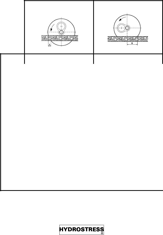
Which size is the surplus of cut?
Table "Overcut" indicates the required surplus of cut in dependence on saw blade diameter and depth of incision.
Depths of cut |
|
Saw blade |
max. depth |
in mm |
of cut |
450 |
12.5 |
500 |
15 |
600 |
20 |
750 |
27.5 |
800 |
30 |
900 |
35 |
1000 |
40 |
1200 |
50 |
1500 |
67 |
1600 |
72 |
1800 |
82 |
Example
LV D SUHYLRXV
LQFLVLRQ
QHFHVVDU\"
PQ
SUHYLRXV
LQFLVLRQ
3UHYLRXV LQFLVLRQ ZLWK VPDOOHU VDZ EODGH PGEGUUCT[
Door opening in a concrete wall with a thickness of 35 cm:
–7KH VDZ EODGH GLDPHWHU PXVW EH DW OHDVW OOVHH WDEOH 'HSWKV RI FXW
–:LWK PD[LPXP GHSWK RI LQFLVLRQ WKH RYHUFXW ZLOO EH
EO
VHH WDEHO 2YHUFXW
Page 18 |
FZ_29811 |
)= 6 |
6HW XS |
Overcut
Thickness of concrete
5 cm
10 cm
15 cm
20 cm
25 cm
30 cm
35 cm
40 cm
45 cm
50 cm
55 cm
60 cm
65 cm
67 cm
Maximum depth of incision |
Minimal depth of incision |
|
|
|
Diameter of saw blade |
|
|
|
|
Diameter of saw blade |
|
|
|
||||||
|
500 |
600 |
750 |
800 |
900 |
1000 |
1200 |
1500 |
|
600 |
750 |
800 |
900 |
1000 |
1200 |
1500 |
|
|
500 |
|
|||||||||||||||
|
|
|
|
|
|
|
|
|
|
|
|
|
|
|
|
|
|
|
2 |
2 |
2 |
2 |
1 |
1 |
1 |
1 |
15 |
15 |
18 |
18 |
20 |
21 |
21 |
27 |
|
|
6 |
5 |
4 |
4 |
3 |
3 |
3 |
2 |
20 |
22 |
25 |
26 |
28 |
29 |
32 |
37 |
|
|
14 |
10 |
7 |
7 |
5 |
5 |
4 |
3 |
23 |
25 |
29 |
31 |
32 |
35 |
39 |
45 |
|
|
- |
18 |
12 |
11 |
9 |
8 |
7 |
5 |
- |
28 |
33 |
34 |
37 |
39 |
44 |
51 |
|
|
- |
- |
19 |
17 |
13 |
12 |
10 |
7 |
- |
- |
35 |
36 |
43 |
43 |
49 |
56 |
|
|
- |
- |
- |
26 |
20 |
17 |
13 |
10 |
- |
- |
- |
38 |
43 |
45 |
52 |
60 |
|
|
- |
- |
- |
- |
30 |
24 |
18 |
13 |
- |
- |
- |
- |
44 |
47 |
54 |
64 |
|
|
- |
- |
- |
- |
- |
36 |
24 |
17 |
- |
- |
- |
- |
- |
48 |
55 |
67 |
|
|
- |
- |
- |
- |
- |
- |
31 |
22 |
- |
- |
- |
- |
- |
- |
57 |
69 |
|
|
- |
- |
- |
- |
- |
- |
44 |
27 |
- |
- |
- |
- |
- |
- |
58 |
71 |
|
|
- |
- |
- |
- |
- |
- |
- |
34 |
- |
- |
- |
- |
- |
- |
- |
73 |
|
|
- |
- |
- |
- |
- |
- |
- |
43 |
- |
- |
- |
- |
- |
- |
- |
73 |
|
|
- |
- |
- |
- |
- |
- |
- |
58 |
- |
- |
- |
- |
- |
- |
- |
74 |
|
|
- |
- |
- |
- |
- |
- |
- |
74 |
- |
- |
- |
- |
- |
- |
- |
74 |
|
|
|
|
|
|
|
|
|
|
|
|
|
|
|
|
|
|
|
FZ_29811 |
Page 19 |

6HW XS |
)= 6 |
5.4 Choosing the saw motor |
Choose the motor like this: |
||
|
1 |
Determine the saw blade diameter |
|
Choosing the appropriate saw motor results |
|||
2 |
Note the type of power unit |
||
in... |
3 |
Choose the table with your power |
|
|
|||
– %HVW FXWWLQJ SHUIRUPDQFH |
|
unit in the header |
|
4 |
Choose the appropriate motor |
||
|
|||
–/HDVW VDZ EODGH ZHDU
–/RQJHVW ZRUNLQJ OLIH :KHQ ZRUNLQJ ZLWK OHYHO SRZHU XQLWV DOZD\V ZRUN ZLWK FROXPQ
++ QT JKIJGT :KHQ HQFRXQWHULQJ UHLQIRUFHPHQWV \RX FDQ WKHQ :KHQ FKDQJLQJ WKH VDZ EODGH DOZD\V PDNH VXUH WKDW \RX DUH DOZD\V UNQY FQYP WR WKH QH[W ORZHU OHYHO XVLQJ WKH DSSURSULDWH PRWRU VL]H
FZ-2S + AD-S3 |
|
|
|
I |
|
|
|
|
|
|
II |
|
|
|
|
|
|
III |
|
|
|
|
|
|
IV |
|
|
|
Motor [ccm] |
|
Ø min |
|
— Ø |
max |
|
Ø min |
|
— Ø |
max |
|
Ø min |
|
— Ø |
max |
|
Ø min |
|
— Ø |
max |
||||||||
8 |
|
- |
|
— |
|
|
- |
|
- |
|
— |
|
|
- |
|
- |
|
— |
|
|
- |
|
- |
|
— |
|
|
- |
11 |
|
- |
|
— |
500 |
|
- |
|
— |
|
|
- |
|
- |
|
— |
|
|
- |
|
- |
|
— |
- |
||||
16 |
|
650 |
|
— |
700 |
|
600 |
|
— |
|
|
650 |
|
500 |
|
— |
|
|
550 |
|
- |
|
— |
450 |
||||
18 |
|
750 |
|
— |
800 |
|
650 |
|
— |
|
|
700 |
|
550 |
|
— |
|
|
600 |
|
450 |
|
— |
500 |
||||
22 |
900 |
|
— |
1000 |
800 |
|
— |
|
|
900 |
650 |
|
— |
|
|
750 |
550 |
|
— |
650 |
||||||||
|
|
|
|
|
|
|
|
|
|
|
|
|
|
|
|
|
|
|
|
|
|
|
||||||
25/26 |
|
1000 |
|
— |
- |
|
900 |
|
— |
1000 |
|
750 |
|
— |
|
|
800 |
|
650 |
|
— |
700 |
||||||
30/31 |
|
1200 |
|
— |
- |
|
- |
|
— |
1200 |
|
900 |
|
— |
1000 |
|
800 |
|
— |
900 |
||||||||
40 |
1600 |
|
— |
1800 |
1500 |
|
— |
1600 |
1200 |
|
— |
|
|
- |
1000 |
|
— |
- |
||||||||||
|
|
|
|
|
|
|
|
|
|
|
|
|
|
|
|
|
|
|
|
|
|
|
||||||
50 |
|
2000 |
|
— |
|
|
2200 |
|
1800 |
|
— |
|
2000 |
|
1500 |
|
— |
|
|
- |
|
- |
|
— |
|
|
- |
|
|
|
|
|
|
|
|
|
|
|
|
|
|
|
|
|
|
|
|
|
|
|
|
|
|
||||
FZ-2S + CR-3 |
|
|
|
I |
|
|
|
|
|
|
II |
|
|
|
|
|
|
III |
|
|
|
|
|
|
IV |
|
|
|
Motor [ccm] |
|
Ø min |
|
— Ø |
max |
|
Ø min |
|
— Ø |
max |
|
Ø min |
|
— Ø |
max |
|
Ø min |
|
— Ø |
max |
||||||||
8 |
|
- |
|
— |
|
|
500 |
|
- |
|
— |
|
|
- |
|
- |
|
— |
|
|
- |
|
- |
|
— |
|
|
- |
11 |
600 |
|
— |
650 |
500 |
|
— |
|
|
550 |
- |
|
— |
|
|
- |
- |
|
— |
- |
||||||||
|
|
|
|
|
|
|
|
|
|
|
|
|
|
|
|
|
|
|
|
|
|
|
|
|
||||
16 |
|
900 |
|
— |
1000 |
|
750 |
|
— |
|
|
800 |
|
600 |
|
— |
|
|
650 |
|
500 |
|
— |
550 |
||||
18 |
|
1000 |
|
— |
- |
|
800 |
|
— |
|
|
900 |
|
650 |
|
— |
|
|
700 |
|
550 |
|
— |
600 |
||||
22 |
1200 |
|
— |
- |
1000 |
|
— |
|
|
- |
800 |
|
— |
|
|
900 |
650 |
|
— |
750 |
||||||||
|
|
|
|
|
|
|
|
|
|
|
|
|
|
|
|
|
|
|
|
|
|
|
||||||
25/26 |
|
- |
|
— |
1500 |
|
- |
|
— |
|
|
- |
|
900 |
|
— |
1000 |
|
750 |
|
— |
800 |
||||||
30/31 |
|
1600 |
|
— |
1800 |
|
- |
|
— |
1500 |
|
- |
|
— |
1200 |
|
900 |
|
— 1000 |
|||||||||
40 |
|
2200 |
|
— |
- |
|
1800 |
|
— |
2000 |
|
1500 |
|
— |
1600 |
|
1200 |
|
— |
- |
||||||||
50 |
|
- |
|
— |
|
|
- |
|
- |
|
— |
|
|
- |
|
1800 |
|
— |
|
2000 |
|
1500 |
|
— |
|
|
- |
|
Base: Vmin = 38 m/s, Vmax = 42 m/s
Page 20 |
FZ_29811 |
)= 6 |
6HW XS |
|
FZ-2S + DK (35 PS Wisconsin) / DK.1 (27 PS Kubota) / DK.2 (27 PS Hatz) |
|
|
|
|
|
|
|
|
|
|
|
|
|
||||||||||||||||||
|
|
|
|
|
|
I |
|
|
|
|
|
|
II |
|
|
|
|
|
|
|
III |
|
|
|
|
|
|
IV |
|
|
|
|
|
Motor [ccm] |
|
|
Ø min |
|
— Ø max |
|
|
Ø min |
|
— Ø |
max |
|
|
Ø min |
|
— Ø |
max |
|
Ø min |
|
— Ø |
max |
|
||||||||
|
8 |
|
|
500 |
|
— |
|
550 |
|
|
- |
|
— |
|
|
- |
|
|
- |
|
— |
|
|
- |
|
- |
|
— |
|
|
- |
|
|
11 |
|
650 |
|
— |
750 |
|
500 |
|
— |
|
|
550 |
|
- |
|
— |
450 |
- |
|
— |
- |
|
|||||||||
|
|
|
|
|
|
|
|
|
|
|
|
|
|
|
|
|
|
|
|
|
|
|
|
|
|
|
|
|||||
|
16 |
|
|
1000 |
|
— |
- |
|
|
750 |
|
— |
|
|
800 |
|
|
600 |
|
— |
700 |
|
500 |
|
— |
550 |
|
|||||
|
18 |
|
|
- |
|
— |
1200 |
|
|
800 |
|
— |
|
|
900 |
|
|
700 |
|
— |
750 |
|
550 |
|
— |
650 |
|
|||||
|
22 |
|
- |
|
— |
1500 |
|
1000 |
|
— |
|
|
- |
|
800 |
|
— |
900 |
700 |
|
— |
750 |
|
|||||||||
|
|
|
|
|
|
|
|
|
|
|
|
|
|
|
|
|
|
|
|
|
|
|
|
|
|
|
|
|||||
|
25/26 |
|
|
1500 |
|
— |
- |
|
|
- |
|
— |
|
|
- |
|
|
1000 |
|
— |
- |
|
800 |
|
— |
900 |
|
|||||
|
30/31 |
|
1800 |
|
— |
2000 |
|
- |
|
— |
1500 |
|
1200 |
|
— |
- |
1000 |
|
— |
- |
|
|||||||||||
|
|
|
|
|
|
|
|
|
|
|
|
|
|
|
|
|
|
|
|
|
|
|
|
|
|
|||||||
|
40 |
|
|
- |
|
— |
- |
|
|
1800 |
|
— |
2000 |
|
|
1500 |
|
— |
- |
|
- |
|
— |
- |
|
|||||||
|
50 |
|
|
- |
|
— |
|
- |
|
|
- |
|
— |
|
|
- |
|
|
- |
|
— |
|
|
- |
|
1600 |
|
— 1800 |
|
|||
|
|
|
|
|
|
|
|
|
|
|
|
|
|
|
|
|
|
|
|
|
|
|
|
|
|
|
|
|
||||
|
FZ-2S + DK-S (48 PS Kubota) / DK-S.1 (48 PS Hatz) / DK-S2 (65 PS Wisconsin) |
|
|
|
|
|
|
|
|
|
||||||||||||||||||||||
|
|
|
|
|
|
I |
|
|
|
|
|
|
II |
|
|
|
|
|
|
|
III |
|
|
|
|
|
|
IV |
|
|
|
|
|
Motor [ccm] |
|
|
Ø min |
|
— Ø max |
|
|
Ø min |
|
— Ø |
max |
|
|
Ø min |
|
— Ø |
max |
|
Ø min |
|
— Ø |
max |
|
||||||||
|
8 |
|
|
- |
|
— |
|
- |
|
|
- |
|
— |
|
|
- |
|
|
- |
|
— |
|
|
- |
|
- |
|
— |
|
|
- |
|
|
11 |
|
|
- |
|
— |
- |
|
|
- |
|
— |
|
|
- |
|
|
- |
|
— |
- |
|
- |
|
— |
- |
|
|||||
|
16 |
|
|
500 |
|
— |
550 |
|
|
- |
|
— |
|
|
450 |
|
|
- |
|
— |
- |
|
- |
|
— |
- |
|
|||||
|
18 |
|
550 |
|
— |
600 |
|
450 |
|
— |
|
|
500 |
|
- |
|
— |
450 |
- |
|
— |
- |
|
|||||||||
|
|
|
|
|
|
|
|
|
|
|
|
|
|
|
|
|
|
|
|
|
|
|
|
|
|
|
|
|||||
|
22 |
|
|
650 |
|
— |
750 |
|
|
550 |
|
— |
|
|
650 |
|
|
500 |
|
— |
550 |
|
- |
|
— |
500 |
|
|||||
|
25/26 |
|
|
750 |
|
— |
800 |
|
|
650 |
|
— |
|
|
700 |
|
|
550 |
|
— |
650 |
|
500 |
|
— |
550 |
|
|||||
|
30/31 |
|
|
900 |
|
— |
1000 |
|
|
800 |
|
— |
|
|
900 |
|
|
700 |
|
— |
750 |
|
600 |
|
— |
650 |
|
|||||
|
40 |
|
|
1200 |
|
— |
- |
|
|
1000 |
|
— |
|
|
- |
|
|
900 |
|
— |
1000 |
|
800 |
|
— |
900 |
|
|||||
|
50 |
|
|
1500 |
|
— |
|
- |
|
|
- |
|
— |
|
|
- |
|
|
- |
|
— |
|
|
- |
|
1000 |
|
— |
|
|
- |
|
|
|
|
|
|
|
|
|
|
|
|
|
|
|
|
|
|||||||||||||||||
|
FZ-2S + >>>>>> |
|
|
BR-4/RA |
|
|
AD-S2/CR-L |
|
|
|
RD (I) |
|
|
RD (II) / RA-RC |
|
|||||||||||||||||
|
|
|
|
BE-S/BE-SB |
|
|
BL-D3/BL-S |
|
|
RD-S (I) |
|
RD-S (II) |
|
|
||||||||||||||||||
|
|
|
|
|
|
|
|
|
|
|
|
|
|
|
|
|
|
|
|
|
|
|
|
|
|
|
|
|
|
|
|
|
|
Motor [ccm] |
|
|
Ø min |
|
— Ø max |
|
|
Ø min |
|
— Ø |
max |
|
|
Ø min |
|
— Ø |
max |
|
Ø min |
|
— Ø |
max |
|
||||||||
|
8 |
|
|
- |
|
— |
|
500 |
|
|
- |
|
— |
|
|
- |
|
|
- |
|
— |
|
|
- |
|
- |
|
— |
|
|
- |
|
|
|
|
|
|
|
|
|
|
|
|
|
|
|
|
|
|
|
|
|
|
|
|
|
|
|
|
|
|||||
|
11 |
|
|
600 |
|
— |
650 |
|
|
- |
|
— |
|
|
500 |
|
|
- |
|
— |
- |
|
- |
|
— |
- |
|
|||||
|
16 |
|
|
900 |
|
— |
1000 |
|
|
650 |
|
— |
|
|
700 |
|
|
500 |
|
— |
550 |
|
- |
|
— |
- |
|
|||||
|
18 |
|
1000 |
|
— |
- |
|
750 |
|
— |
|
|
800 |
|
550 |
|
— |
600 |
- |
|
— |
450 |
|
|||||||||
|
|
|
|
|
|
|
|
|
|
|
|
|
|
|
|
|
|
|
|
|
|
|
|
|
|
|||||||
|
22 |
|
|
1200 |
|
— |
- |
|
|
900 |
|
— |
1000 |
|
|
650 |
|
— |
750 |
|
550 |
|
— |
600 |
|
|||||||
|
25/26 |
|
|
- |
|
— |
1500 |
|
|
1000 |
|
— |
|
|
- |
|
|
750 |
|
— |
800 |
|
600 |
|
— |
650 |
|
|||||
|
30/31 |
|
1600 |
|
— |
1800 |
|
1200 |
|
— |
|
|
- |
|
900 |
|
— |
1000 |
700 |
|
— |
800 |
|
|||||||||
|
|
|
|
|
|
|
|
|
|
|
|
|
|
|
|
|
|
|
|
|
|
|
|
|
|
|||||||
|
40 |
|
|
2200 |
|
— |
- |
|
|
1600 |
|
— |
1800 |
|
|
1200 |
|
— |
- |
|
1000 |
|
— |
- |
|
|||||||
|
50 |
|
|
- |
|
— |
|
- |
|
|
2000 |
|
— |
|
2200 |
|
|
1500 |
|
— |
|
|
- |
|
1200 |
|
— |
|
|
- |
|
|
FZ_29811 |
Page 21 |

6HW XS
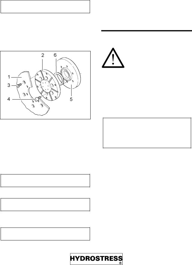
5.5Changing the saw motor
Removing the saw motor
Never connect or disconnect hoses when the unit is running.
•Turn off power unit
•Turn the pressure control to zero
•Disconnect the hoses from the saw motor
–Turn the locking ring
–Hold the hose end in straight position
–Push back the coupling sleeve
–Remove the hose
Always keep the hose couplings clean. Leave the hose connected to the unit so that pressure could be relieved via the unit.
•Remove the allen head screws.
•Turn the saw motor and remove it.
Mounting the saw motor (Size 2)
•Put the saw motor straight on to the drive shaft and turn it
•Tighten the screws (M8)
Mounting the saw motor (Size 3)
•Remove the double thoothed profile clutch
•Put the saw motor straight on to the driving shaft and turn it
•Tighten the screws (M10)
)= 6
Connecting the hoses
•Push the hose coupling on or into its counterpart until you hear it "click"
•Turn the locking ring of the coupling into its secured position
Always make sure that the hoses are properly connected. Always secure them by turning the locking ring.
Fig. montmot.tif
$OOHQ KHDG VFUHZ 0 [
6DZ PRWRU VL]H
'RXEOH WRRWKHG SURILOH FOXWFK
'ULYH VKDIW
$OOHQ KHDG VFUHZ 0 [
6DZ PRWRU VL]H
Page 22 |
FZ_29811 |

)= 6 |
6HW XS |
5.6Fixing the tracks on concrete
Pay attention to the following instructions. Inappropriate fixing leads to serious hazards!
Always use:
–7HQVLRQLQJ EORFNV ZLWK DOO VFUHZV
–'RZHO EROWV ZLWK ‘ PP DQG N1 RI WUDFWLRQ VHH$FFHVVRULHV
–6FUHZV OHQJWK PP
–WZR WUDFN EDVHV IRU WKH ILUVW WUDFN QPG IRU DOO IXUWKHU WUDFNV
Fig. fz4-2b.tif
7UDFN
&ODPSLQJ GHYLFH
7HQVLRQLQJ QXW
$GMXVWLQJ VFUHZ
'RZHO EROW
7HQVLRQLQJ EORFN
/XEULFDWLQJ QLSSOH
$GMXVWLQJ VFUHZ
7UDFN EDVH
Procedure
•Mark the cutting line
•Mark the dowel line in sections of 22 cm (for flush cutting 24 cm)
•Mount the tracks (1) to the track bases (9).
Distance between track bases:
-as big as possible when using one track only
-equally distributed along the whole cutting distance when using more then one track
Unscrew the adjusting screws (4) until the track base is at least 2 cm above the concrete, otherwise the swivel arm will brush against the concrete.
•Fix the tracks to the concrete and align them with a distance of 8 cm (10 cm for flush cutting) to the cutting line
•Align the tracks by means of the adjusting screw (8) so that all adjusting screws are in contact with the concrete surface.
•Make sure that the tracks are in true alignement and without distance at the joints.
•Mount the track end stopper so that the wall saw can’t fall off the track.
Fig. fz4-3a.tif
FZ_29811 |
Page 23 |

6HW XS |
)= 6 |
5.7Mounting the wall saw head
Fig. wamont.tif
|
< JULS |
|
)HHG KDQGOH |
|
+DQGOH |
|
JXLGLQJ GHYLFHV |
Procedure
Mount wall saw head without saw blade
Fig. schlitt.tif
7XUQNH\ ORFN
< +DQGOH
)HHG +DQGOH
Fig. y_fuerg1.tif
•Turn Y-Handle (2). The turnkey lock (1) will angage
5.8Fasten the adjusting grips
Fig. y_fuerg2.tif
•Turn positioning handle (3) clockwise until the prism fits tightly against the rail
•turn back 2 engaging positions
Page 24 |
FZ_29811 |

)= 6
5.9Release of the carriage guides
Fig.Y_FUERG3.tif
•Push turnkey lock with thumb and simultaneously...
•...turn Y-handle counter-clockwise
5.10Mounting blade and blade guard or flush cutting flange
If the saw blade is not mounted correctly it can get loose and harm people seriously!
When the power unit is running or even the hoses are under pressure a blade can start to turn suddenly and harm people seriously!
•Always turn off and plug out the power unit and relieve the pressure from the hoses.
6HW XS
Preparations
•Move the swivel arm to the uppermost position
•Mount the saw blade so that the arrow points counter-clockwise.
Mounting saw blade and blade guard
Fig. fz4-5.tif
Fig. funktion.tif
6DZ EODGH
6DZ EODGH FRYHU
$OOHQ KDHG VFUHZV 0 [
%ODGH KXE
+H[DJRQ KHDG FDS VFUHZ 0 [
FZ_29811 |
Page 25 |
6HW XS
•Fasten the saw blade with saw blade cover and central lockscrew M16x30, or with saw blade cover and six screws M8x16
8VH RQO\ WKHVH VFUHZV 0 [ TXDOLW\ ',1
2UGHU 1R ,
•Check the blade angle and readjust track bases
•Mount the blade guard
Mounting saw blade and flush cutting flange
Fig. fz4-6.tif
6DZ EODGH
)OXVK FXWWLQJ IODQJH
$OOHQ KHDG FRXQWHUVXQN VFUHZV 0 ;
$OOHQ KHDG VFUHZV 0 [
%ODGH KXE
)ODW SDFNLQJ
• Fasten flush cutting flange with six screws
8VH RQO\ WKHVH VFUHZV 0 [ TXDOLW\ ',1
2UGHU QR ,
• Fasten the saw blade with six screws
8VH RQO\ WKHVH VFUHZV 0 [ TXDOLW\ ',1
2UGHU QR ,
•Check the blade angle and readjust track bases
)OXVK FXWWLQJ LV RQO\ SRVVLEOH ZLWK WKH WZR SLHFH EODGH JXDUGDOXPLQXP
)= 6
•Remove the cover plate from the blade guard
After flush cutting
•Remount the cover plate to the blade guard.
5.11 Connecting the power unit
Fundamentals
Never connect or disconnect hoses when the unit is running.
•Connect couplings with elbow pieces to the wall saw system
•Connect straight couplings to the power unit
•Keep the couplings clean
Connect both ends of the hose package. Thus the hose couplings are kept clean and will not be damaged during transport.
If the hoses can not be connected easily they are under pressure (see below).
Relieving pressure in the hose
1At the power unit: Actuate the main circuit valve or the spool valve several times
2At the hose: Put the supplied pressure relief valve on the coupling and srew it in
Page 26 |
FZ_29811 |

)= 6
Connecting the hoses
Turn the pressure valve at the power unit to zero
The following hose connections are to be es-
tablished:
Wall saw system |
Power unit |
Saw motor |
Main circuit |
Swivelling motor |
Feed circuit |
Feed motor |
Feed circuit |
Water connection |
Water connection |
|
|
|
|
Fig. fz5-2.tif
•Push the hose coupling on or into its counterpart until you hear it ”klick”
•Turn the locking ring of the coupling into its secured position
Never force connections
6HW XS
Check the moving sense of the wall saw head and the swivelling arm now
FZ_29811 |
Page 27 |

6DZLQJ |
)= 6 |
6 Sawing
6.1Before sawing
Never saw without blade guard.
Pay attention to the following instructions:
•Check the moving sense of the wall saw head and the swivelling arm
•The toothing of the track must be clean
•Make a "trial run " along the whole length of the tracks and make sure that the hoses are not clogged
6.2The first cut
Fig. fz6-1.tif
• Cover sharp-edged objects along the tracks to protect the hoses
•Check whether all dowel bolts at the track bases are firmly tightened
•Check whether the water emerges properly at the pivot of the saw blade
Important:
-Sense of rotation with the feed sense
-Swivel arm must be drawn
-Cutting depth: 5 - 10 cm
-Only saw at half power
Procedure
•Close the feed circuit valves at the power unit
•Drive the wall saw head to start position
•Saw
Page 28 |
FZ_29811 |
)= 6 |
6DZLQJ |
6.3After the first cut
Further infeed
After the first cut further infeed can be more than 5-10 cm. The depth of cut depends on the power of the connected power unit, the size of the saw blade the quality of the diamond segments and the quality of the concrete.
Optimum depth of cut can vary between 5 and 15 cm.
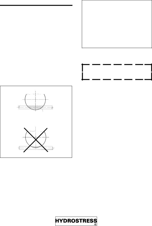
Sawing reinforcements
When sawing in longitudinal direction of the reinforcements:
Fig. fz6-2.tif
•Cut deep enough to saw through the reinforcement completely
•If the reinforcement is not cut through completely the wall saw will deviate
Do not saw with the highest admissible pressure of the power unit in sections where only concrete is sawed. Stay about 40 bar below. If the blade encounters reinforcement the pressure will then not exceed the admissible maximum.
Always withdraw the saw blade while it is still rotating.
If the saw blade is blocked
Never attempt to free the saw blade by strong feed force.
•Withdraw the blade carrying out swivelling or feed motions carefully.
•If you do not succeed, disconnect the saw blade from the wall saw head and remove the saw blade from the incision.
End of cut
•Withdraw the saw blade while it is still rotating
•Move the swivel arm to the uppermost position
•Switch off blade drive
FZ_29811 |
Page 29 |

6DZLQJ |
)= 6 |
6.4End of machining
•Turn off power unit and unplug mains
•Relieve pressure from the hydraulic circuits
•Clean wall saw system, e.g. by hosing it down
•Remove blade guard
•Remove saw blade and keep screws safely or screw them back into holes
•Disconnect hoses
–Turn the locking ring
–Hold the hose end in straight position
–Push the coupling sleeve back
–Remove the hose
–Connect both ends of the hose package in order to keep the couplings clean and protect them from damage during transport
•Unscrew the guide grips completely
•Remove the wall saw head
•Remove the tracks
Page 30 |
FZ_29811 |
 Loading...