

Page 1
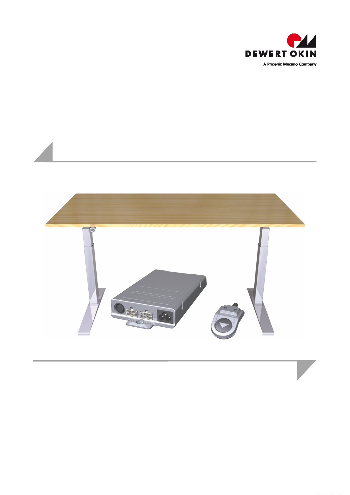
Installation Instructions
(Translation of the original installation instructions)
System ID21
Page 2

Page 3

System ID21
Document revision history
Version Date Modification, change
(-) 07/2011 First release
(a) 05/2015 Control keypads, control
(b) 01/2016 Note for Reset
(c) 03/2017 DESKFRAME C ID-A 30x30-3L
(d) 05/2017 DESKFRAME C ID-A 40x40-3L
6.0 11/2018 Edition II
7.0 07/2019 Control unit SMARTneo (pro)
units
Disclaimer and exclusion of liability
DewertOkin is not responsible for damage resulting from:
• failure to observe these instructions,
• changes made to this product which have not been approved by DewertOkin, or
• the use of replacement parts which have not been approved or manufactured by DewertOkin.
We reserve the right to make unannounced technical changes in the course of our continual
product improvement process!
Creation of a complete operating instruction manual for the entire end product
These instructions are only intended to be used by the end-product manufacturer. They should
not be given to the operator of the end product. The factual information contained within may
be used as a basis when creating the end-product manual.
The warning and danger notices are best suited for use in the end product's manual. However
it is not sufficient to simply follow these notices. You should also carry out an internal risk assessment for your end product. This can then be used as the basis for the safety notices in
your manual.
These installation instructions do not contain all information required to safely operate the end
product. They only describe the installation and operation of the drive as partially completed
machinery.
The instructions are intended for the technicians responsible for manufacturing an end product
and not for the operators of the end product.
78438 7.0 3
Page 4

System ID21
Document revision history .............................................................................................................................. 3
Disclaimer and exclusion of liability ............................................................................................................... 3
Creation of a complete operating instruction manual for the entire end product ..................................... 3
1. General Information ................................................................................................. 6
1.1 About these installation instructions ................................................................................................. 6
1.2 Safety notices within the installation instruction and the operating instructions for the
entire machine ...................................................................................................................................... 7
1.3 Conventions used ................................................................................................................................ 7
2. Safety notices .......................................................................................................... 8
2.1 Proper and intended usage ................................................................................................................. 8
2.2 Selection and qualification of personnel ........................................................................................... 9
3. System component description ........................................................................... 10
3.1 Complete installed system ................................................................................................................ 10
3.2 Complete installed system ................................................................................................................ 11
3.3 SMART and COMPACT control units ............................................................................................... 12
3.4 Control keypads ................................................................................................................................. 13
3.5 ID21 lifting column ............................................................................................................................. 21
4. Configuration options for the ID21 system ......................................................... 22
5. Installation .............................................................................................................. 24
5.1 Safety notices to observe during installation ................................................................................. 24
5.2 Installing the ID21 lifting columns .................................................................................................... 26
5.3 Installing the control keypads........................................................................................................... 30
5.4 Installing the SMART/COMPACT control units ............................................................................... 36
5.5 Electrical connections for the SMART/COMPACT control units ................................................... 40
5.6 Mounting the sensor unit .................................................................................................................. 43
6. Initial commissioning ............................................................................................ 51
6.1 Reset during initial commissioning and after the removal of connecting cables ...................... 51
7. Notes for operation ................................................................................................ 52
7.1 General information ........................................................................................................................... 52
8. Operating the control keypads ............................................................................. 54
4 78438 7.0
Page 5

System ID21 General Information
8.1 Functions of the Motion Assist control keypad .............................................................................. 54
8.2 Functions of the HSCO control keypad ........................................................................................... 55
8.3 Functions of the HSU Varioline control keypad .............................................................................. 56
8.4 Functions of the HSU control keypad .............................................................................................. 57
8.5 Functions of the HSF control keypad .............................................................................................. 59
8.6 Functions of the TOUCHbasic-inlay keypad ................................................................................... 62
8.7 Functions of the TOUCHbasic-down keypad .................................................................................. 63
8.8 Functions of the TOUCHfx keypad ................................................................................................... 64
8.9 Functions of the TOUCHdown keypad ............................................................................................. 66
8.10 Functionality of the TOUCHinlay keypad ......................................................................................... 68
9. Troubleshooting .................................................................................................... 70
9.1 Malfunctions ....................................................................................................................................... 70
9.2 Error messages on the control keypad's display ........................................................................... 71
9.3 Error messages, as indicated by clicking tones from the control unit ........................................ 74
9.4 Error messages displayed by the LEDs (COMPACT control unit) ................................................ 74
10. Maintenance and cleaning .................................................................................... 75
10.1 Maintenance ........................................................................................................................................ 75
10.2 Cleaning .............................................................................................................................................. 75
11. Technical specifications and product designation ............................................. 76
11.1 Table .................................................................................................................................................... 76
11.2 SMART and COMPACT control units ............................................................................................... 77
11.3 Dimensions of the SMARTeco control unit ..................................................................................... 79
11.4 Dimensions of the SMARTneo / SMARTneo-pro control unit ........................................................ 80
11.5 Size of COMPACT control unit .......................................................................................................... 81
11.6 ID21 lifting column ............................................................................................................................. 82
11.7 Size of the ID21 lifting column .......................................................................................................... 83
11.8 Product labelling ................................................................................................................................ 84
12. Disposal .................................................................................................................. 91
12.1 Packaging material ............................................................................................................................. 91
12.2 Drive components .............................................................................................................................. 91
Declaration of incorporation/installation ..................................................................................................... 92
EU Declaration of Conformity ....................................................................................................................... 93
78438 7.0 5
Page 6
General Information System ID21
1. General Information
1.1 About these installation instructions
These installation instructions are not specific operating instructions for the end product.
Rather, they describe the functions of the control keypads and the installation of the ID21 system components:
• ID21 lifting columns
• DESKFRAME C ID-A 30x30 (two lifting columns)
• DESKFRAME C ID-A 40x40 (two lifting columns)
• DESKFRAME C ID-A 30x30-3L (three lifting columns)
• DESKFRAME C ID-A 40x40-3L (three lifting columns)
• Control keypads
• SMART and COMPACT control units
These instructions will help you to minimize danger, repair costs and down times. They will
also help you to maximize the reliability and lifespan of the end product.
NOTICE
Please also refer to the installation instructions (leaflet) supplied with each ID21 system.
CAUTION
The notices in these instructions must be followed! Following the guidelines during installation and
connection procedures will help to minimize:
• the risk of accident and injury, and
• damage to the drive system or the end product.
These installation instructions have been written with due care and attention. However, we
cannot guarantee that the data, images and drawings are complete and correct nor do we accept any liability for the information contained therein, unless required by law.
We reserve the right to make unannounced technical changes in the course of our continual
product improvement process!
Availability of this document
As manufacturer of the end product, you are obligated to comply with Machinery Directive
2006/42/EC. This directive stipulates that the installation instructions must be kept on file for
governmental inspection purposes.
Keep these instructions in a safe place!
Application
These testing principles apply towards the testing and certification of sitting/standing desks
used for office, meeting, conference and training rooms. The work tables can be adjusted and
used for both sitting and standing work conditions.
6 78438 7.0
Page 7
System ID21 General Information
1.2 Safety notices within the installation instruction and the operating instructions for the entire machine
The manufacturer of the complete machine (the end product) is only permitted to operate the
ID21 lifting columns (by itself an incomplete machine)
• when the end product (for which the ID21 lifting column is intended) is in compliance with
all protective measures specified in the Machinery Directive 2006/42/EC, and
• when the manufacturer expressly declares the compliance of the end product.
The manufacturer of the end product must create a manual for the users of that product. The
safety notices in the end-product manual must be written based on the end product's risk assessment.
1.3 Conventions used
Notices which do not relate to safety are indicated in these instructions with a symbol:
Triangular notice symbol
Explanations of warning notices
CAUTION
CAUTION indicates a hazardous situation which, if not avoided, could result in minor or moderate
injury.
NOTICE
NOTICE is used to address practices which are not related to personal injury but may result in
damage to the product or surroundings.
78438 7.0 7
Page 8
Safety notices System ID21
2. Safety notices
2.1 Proper and intended usage
The ID21 system is intended to be used for adjusting the height of tables in conjunction with
the SMART/COMPACT control units and the ID21 lifting column from DewertOkin.
It may only be used for applications where unintended motion cannot lead to damage.
It may only be used in dry rooms.
DESKFRAME C ID-A 30x30 / DESKFRAME C ID-A 40x40 / DESKFRAME C ID-A 30x30-3L /
DESKFRAME C ID-A 40x40-3L:
This height-adjustable table (without tabletop*) for office work
is designed for working while sitting,
sitting and standing or
only standing
when a tabletop is already present.* (ID21 system, type A, EN527-1)
CAUTION
Risk of accident
The ID21 system should only be used for the purpose described above. Any other use is forbidden. Improper usage can lead to accidents or destruction of the unit. Such non-approved applications will lead immediately to the expiration of all guarantee and warranty claims on the part of the
end-product manufacturer against the manufacturer.
Improper usage
Be sure to follow the notices below concerning improper usage. You should include them in
your product manual in order to inform the users of your end product.
The ID21 system should not be used:
with a medical product, or installed in a medical product,
as a power source for toys or games,
in a moist environment, or
outdoors.
* The tabletop will be provided and installed by the manufacturer of the end product.
8 78438 7.0
Page 9
System ID21 Safety notices
NOTICE
When installing and operating the lifting column, please note the following:
• Handle the lifting column with care!
• Do not drop the lifting column vertically to the ground.
• Do not tilt the lifting column sideways and let it fall to the ground.
• Do not subject the lifting column to lateral shock loads during the installation.
The ID21 system can be used by children of 8 years and older, persons with reduced physical,
sensory or mental capabilities, or persons with lack of experience or knowledge when they are
supervised or instructed concerning the safe use of the device and when they understand the
resulting risks. Do not allow children to play with this device. The cleaning and user maintenance must not be carried out by children without supervision.
You should only use spare parts which have been manufactured or approved by DewertO-
kin. Only these parts will guarantee a sufficient level of safety.
CAUTION
Danger of pinching/crushing injuries!
There is a danger of being crushed when the table position is changed. This is particularly true
when there is no protective mechanism guarding against crushing injuries. However, crushing
injuries may even occur in exceptional cases when a safety guard is installed. Make sure that
there are no persons within the danger zone and that nobody reaches into the danger zone. This
also applies in the following situations:
• In the event of a malfunction, the table may move a bit during an adjustment before the
safety shutdown mechanism triggers. This could result in a crushing injury.
• The impact protection mechanism is not active during resets and end-position queries.
This could result in a crushing injury.
2.2 Selection and qualification of personnel
The installation of the drive in the end product may only be performed by qualified personnel.
You should only install this drive when you are qualified to do so. Otherwise, a properly qualified person should be found for this task.
78438 7.0 9
Page 10
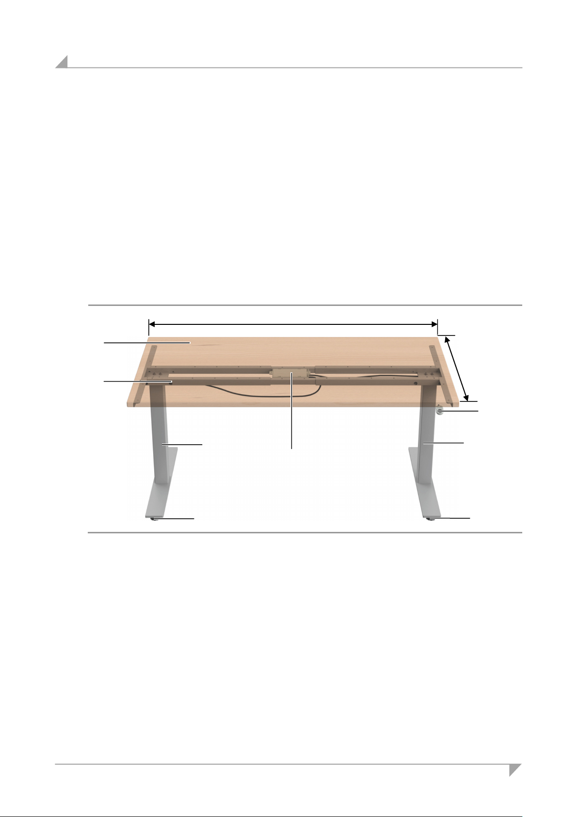
System component description System ID21
A Traverse cross bar
B Tabletop
C
D
E Table base
F Control keypad
A C B D E D E
800 - 1000
max. 2000
F
3. System component description
The ID21 system uses lifting columns to adjust the height of tables. A table-mounted control keypad
and the SMART/COMPACT control units can be used for the adjustments.
The ID21 system variants can differ by:
• the type of control keypads,
• the number of lifting columns that can be connected,
• the type and number of control units connected.
3.1 Complete installed system
• DESKFRAME C ID-A 30x30
• DESKFRAME C ID-A 40x40
Figure 1 Example: ID21 system with two ID21 lifting columns
SMART or COMPACT control units
3.1.1 Dimensions
Specifications for the installed system:
• Max. lengthwise extension: 1200 – 2000 mm
• Max. transverse extension: 800 – 1000 mm
• Tabletop size: 2000 x 800 mm must not be exceeded
• Max. load for the frame: 120 kg (including tabletop)
• Lifespan: max. 10,000 cycles (with load)
10 78438 7.0
ID21 lifting column (double telescopic)
Page 11
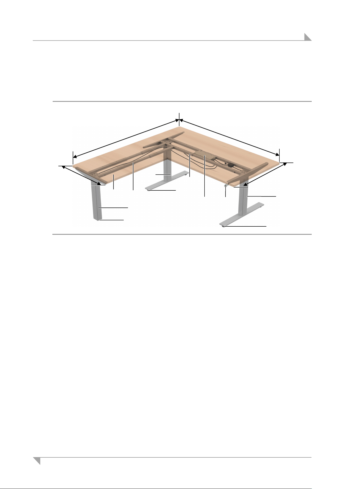
System ID21 System component description
A Tabletop
B Control keypad
C COMPACT control unit
D ID21 lifting column (double telescopic)
E Table base
F Traverse cross bar for two lifting columns
G
C D E D E D E
max. 1000
max. 2000
max. 1000
A B F G max. 1500
3.2 Complete installed system
• DESKFRAME C ID-A 30x30 + DESKFRAME C ID-A 30x30-3L
• DESKFRAME C ID-A 40x40 + DESKFRAME C ID-A 40x40-3L
Figure 2 Example: ID21 system with three ID21 lifting columns
Traverse cross bar (extension with one
lifting column)
(DESKFRAME C ID-A 30x30-3L
DESKFRAME C ID-A 40x40-3L)
3.2.1 Dimensions
Specifications for the installed system:
• Max. lengthwise extension: 1200 – 2000 mm
• Max. transverse extension: 800 – 1000 mm
• The max. permissible tabletop size is (1200-2000) x (800-1000) x (1200-1500) mm.
• Max. load for the frame: 150 kg (including tabletop)
• Lifespan: max. 10,000 cycles (with load)
(DESKFRAME C ID-A 30x30
DESKFRAME C ID-A 40x40)
78438 7.0 11
Page 12
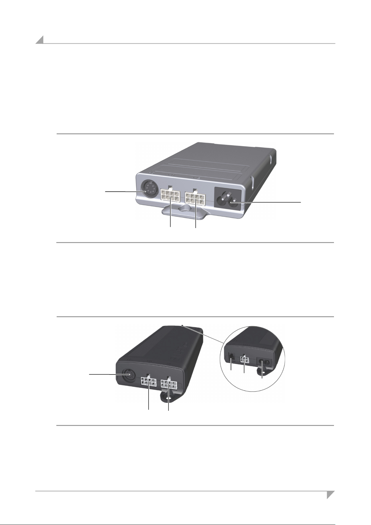
System component description System ID21
A Connection for the control keypad
B Mains power supply connection
C
A Connection for the control keypad
B Sensor connection (only for SMARTneo-pro)
C Cascading connection
D Mains power supply connection
E Connection for the lifting columns
C C A B E E A B C
D
3.3 SMART and COMPACT control units
The SMART and COMPACT control units have an enclosure with connections for the power
supply, lifting columns, and for the control keypad.
3.3.1 Control unit SMARTeco
The SMARTeco control unit is used for adjusting one or two lifting columns.
Figure 3 SMARTeco control unit
Connection for the lifting columns
3.3.2 SMARTneo / SMARTneo-pro control unit
The SMARTneo and SMARTneo-pro control units are used to adjust one or two lifting columns.
Figure 4 SMARTneo / SMARTneo-pro control unit
12 78438 7.0
Page 13
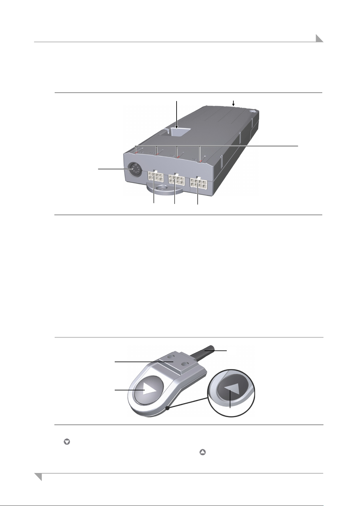
System ID21 System component description
A
B
C Connection for the lifting columns
D Status LEDs
E Sensor connection / cascade connection
A key (adjusting down)
D A B C A D E B C C C
3.3.3 COMPACT control unit
The COMPACT control unit is used for adjusting one, two or three lifting columns.
Figure 5 COMPACT control unit
Connection for the control keypad
3.4 Control keypads
The control keypads are used to adjust the table height, to save positions (optional), and to adjust motor group 2. The table positions and optional saved (programmed) positions can be
moved to directly.
3.4.1 Motion Assist control keypad
The Motion Assist control keypad has two keys for the up and down adjustments.
Mains power supply connection
Figure 6 Motion Assist control keypad
C Connection cable D key (adjusting up)
78438 7.0 13
B Mounting surface
Page 14
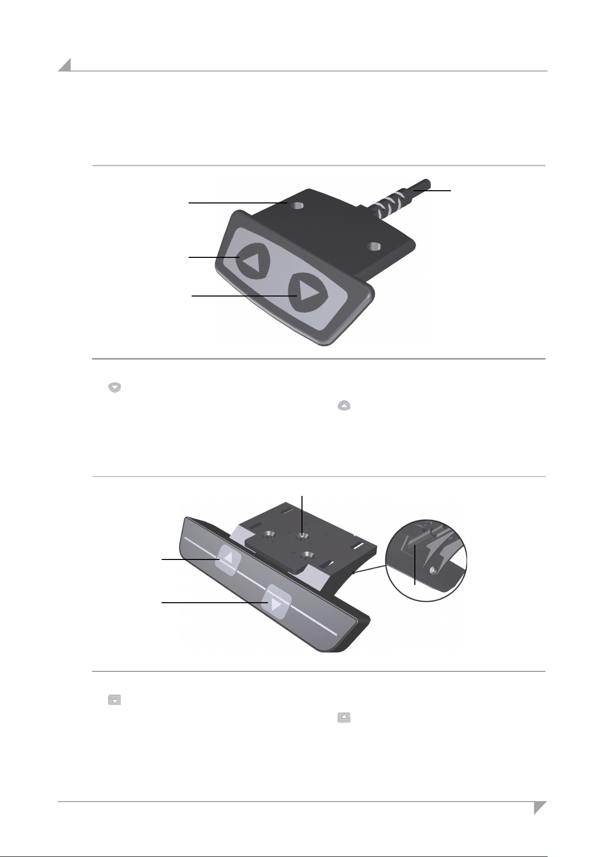
System component description System ID21
A key (adjusting down)
B Mounting surface
A key (adjusting down)
C Connection cable
D key (adjusting up)
D
B C A
D A C
B
3.4.2 HSCO control keypad
The HSCO control keypad has two keys for the up and down adjustments.
Figure 7 HSCO control keypad
C Connection cable D key (adjusting up)
3.4.3 HSU Varioline control keypad
The HSU Varioline control keypad has two keys for the up and down adjustments.
Figure 8 HSU Varioline control keypad
14 78438 7.0
B Mounting surface
Page 15
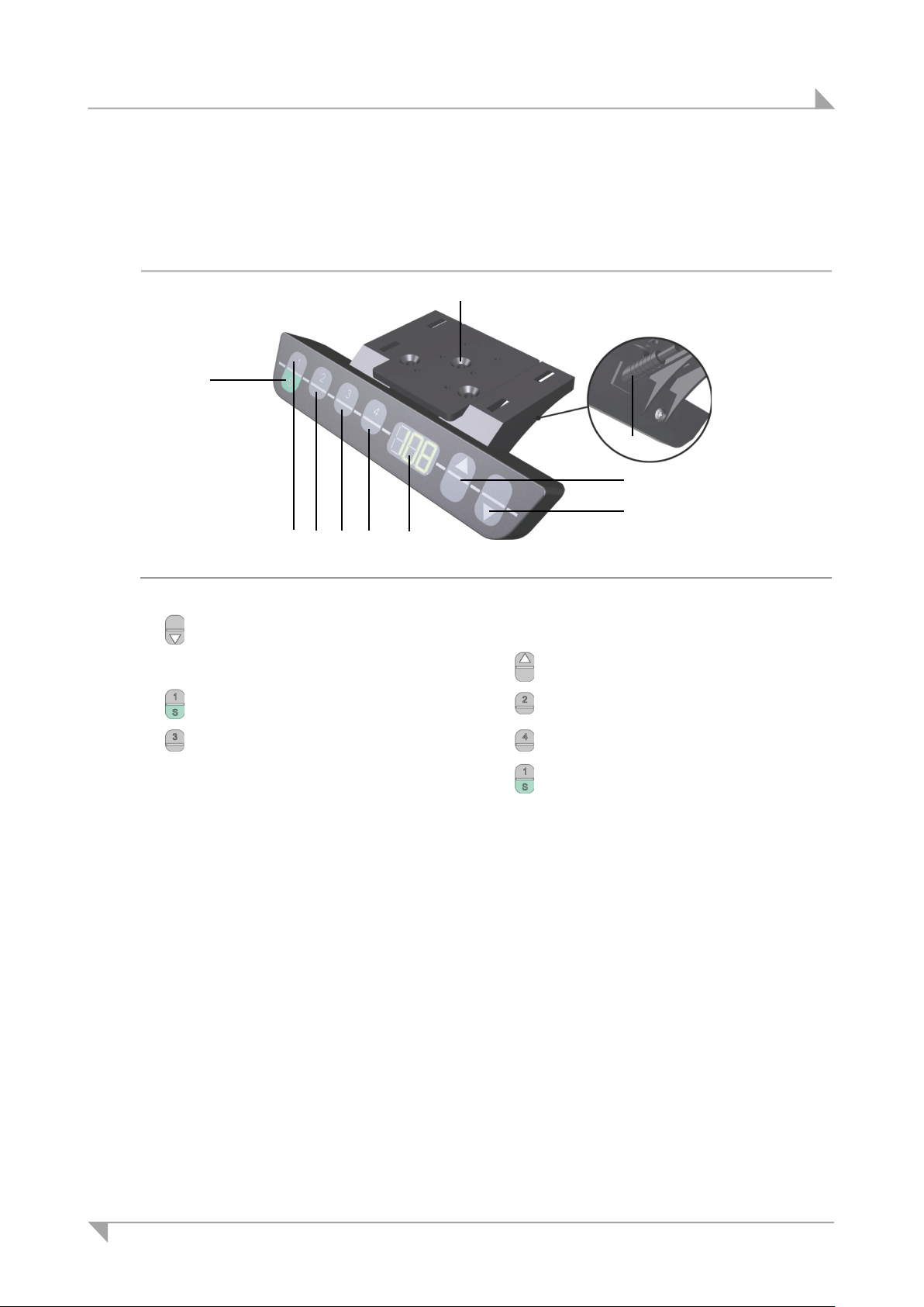
System ID21 System component description
E
D
C
B A I H G F J
3.4.4 HSU control keypad
The HSU control keypad has two keys for the up/down adjustment movements, four memory
keys, a save key and a display.
Figure 9 HSU control keypad
A key (adjusting down) B Mounting surface
C Connection cable D key (adjusting up)
E memory key 1 F memory key 2
G memory key 3 H memory key 4
I Display J save key
78438 7.0 15
Page 16
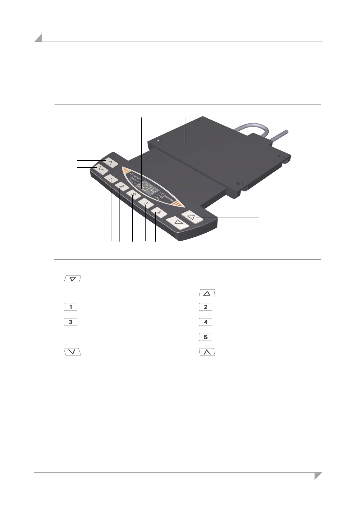
System component description System ID21
E D C
B
A
H
G J F
I
L
K
3.4.5 HSF control keypad
The HSF control keypad has two keys for the up/down adjustment movements, four memory keys,
two keys for motor group 2, a save key and a display.
Figure 10 HSF control keypad
A key (adjusting down)
C Connection cable
E
G
I
K
memory key 1
memory key 3
Display
F
H
motor group 2, adjust downward
B Mounting surface
D key (adjusting up)
J
L
memory key 2
memory key 4
save key
motor group 2, adjust upward
16 78438 7.0
Page 17
System ID21 System component description
D A D A B
C
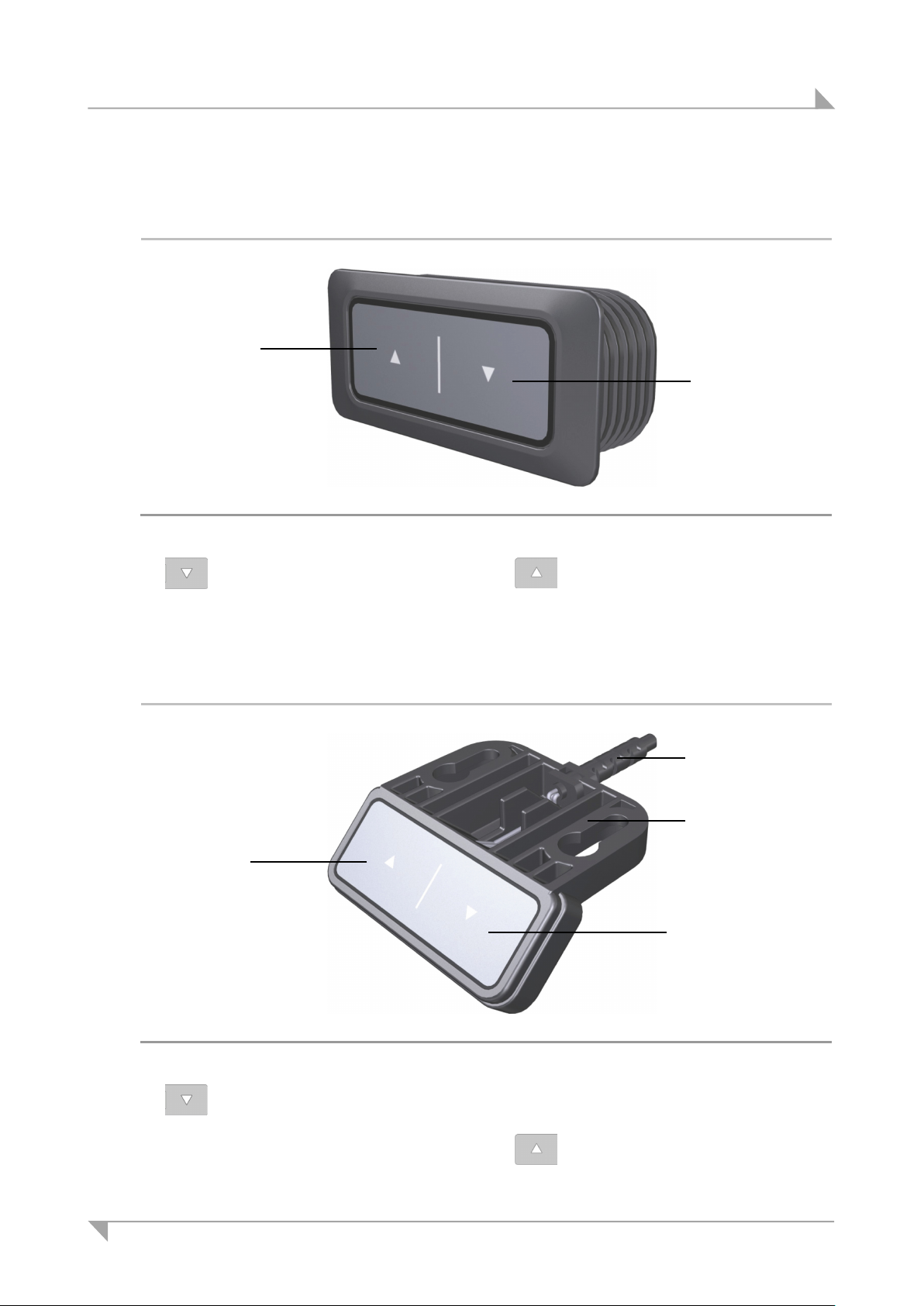
3.4.6 TOUCHbasic-inlay control keypad
The TOUCHbasic-inlay keypad has two keys for the up and down adjusting movements.
Figure 11 TOUCHbasic-inlay control keypad
A key (adjusting down) D key (adjusting up)
3.4.7 TOUCHbasic-down control keypad
The TOUCHbasic-down keypad has two keys for the up and down adjusting movements.
Figure 12 TOUCHbasic-down control keypad
A key (adjusting down)
C Connection cable
78438 7.0 17
B Mounting surface
D key (adjusting up)
Page 18
System component description System ID21
E D B C F H G I J A
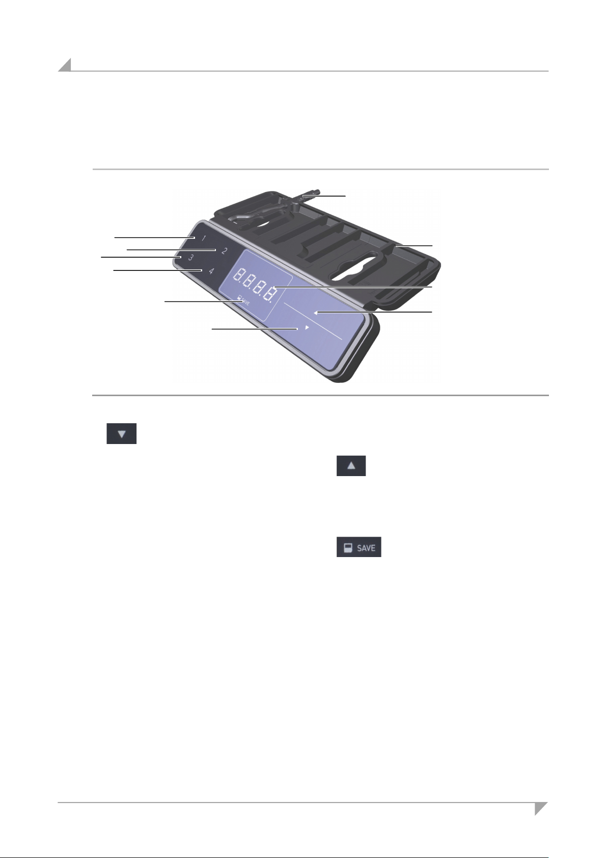
3.4.8 TOUCHfx control keypad
The TOUCHfx control keypad has two keys for the up/down adjustment movements, four memory
keys, a save key and a display.
Figure 13 TOUCHfx control keypad
A key (adjusting down)
C Connection cable
B Mounting surface
D key (adjusting up)
E Memory key 1 F Memory key 3
G Memory key 2 H Memory key 4
I Display
J save key
18 78438 7.0
Page 19
System ID21 System component description
E
D
B F H G I J A
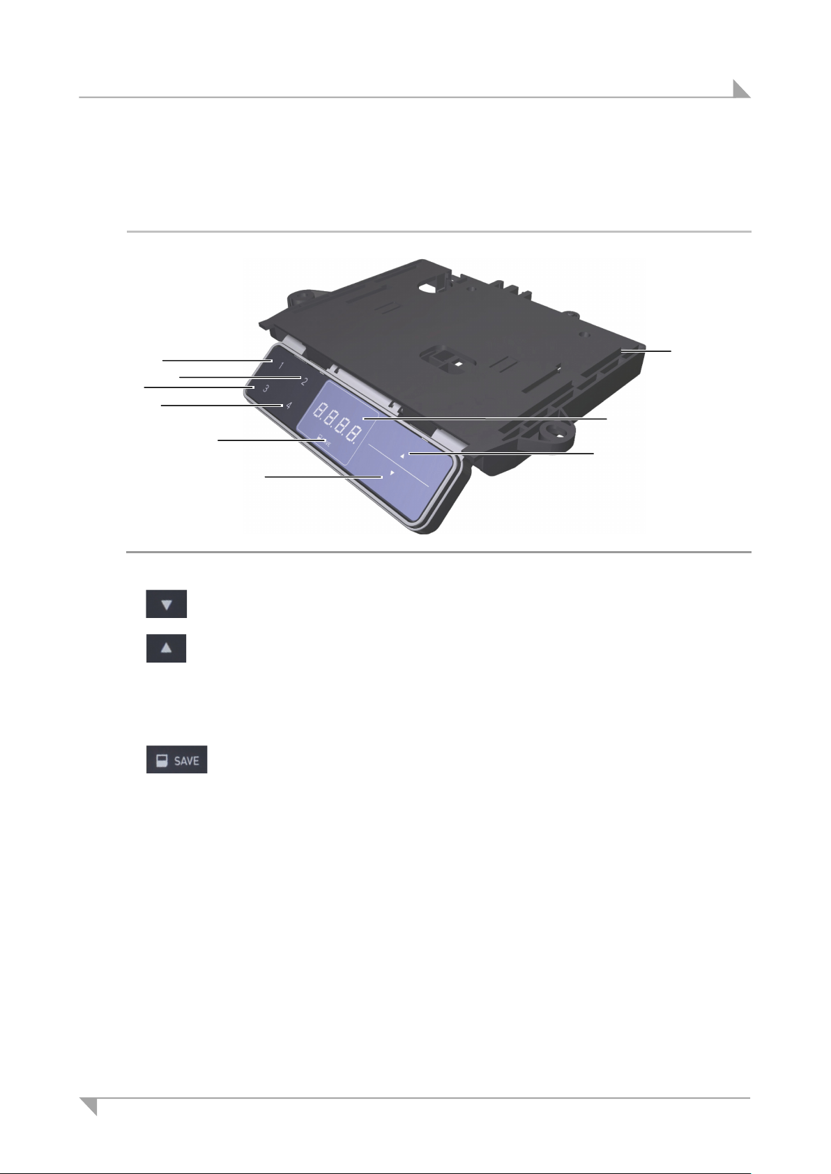
3.4.9 TOUCHdown control keypad
The TOUCHdown control keypad has two keys for the up/down adjustment movements, four memory keys, a save key and a display.
Figure 14 TOUCHdown control keypad
A key (adjusting down)
D key (adjusting up)
F Memory key 2 G Memory key 3
H Memory key 4 I Display
J save key
B Mounting surface
E Memory key 1
78438 7.0 19
Page 20
System component description System ID21
E A D F J
I
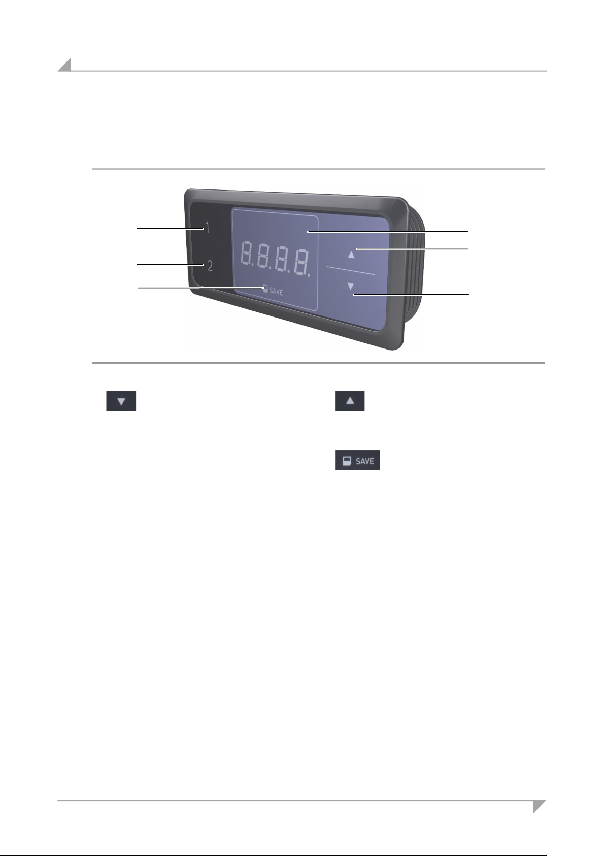
3.4.10 TOUCHinlay control keypad
The TOUCHinlay control keypad has two keys for the up/down adjustment movements, two
memory keys, a save key and a display.
Figure 15 TOUCHinlay control keypad
A key (adjusting down) D key (adjusting up)
E Memory key 1 F Memory key 2
I Display
J save key
20 78438 7.0
Page 21
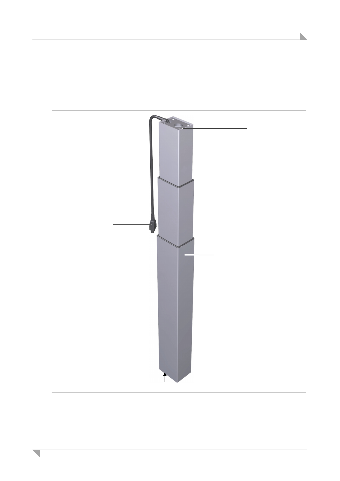
System ID21 System component description
C Outer column with two internal telescopic
D Foot of the lifting column
D
B A B
3.5 ID21 lifting column
The main components of the ID21 lifting column are the electric motor, the telescopic columns for
adjustments, the outer support column, and the control cable. The end product will be attached to
the head of the lifting column. The foot base is attached to the foot end of the lifting column. Positional sensors are built in to allow for synchronized adjustments with multiple columns.
Figure 16 Major components of the ID21 lifting column
A Connection cable B Head of the lifting column
columns
78438 7.0 21
Page 22
Configuration options for the ID21 system System ID21
Installation steps:
Connect the power supply cable
Installation steps:
Connect the power supply cable
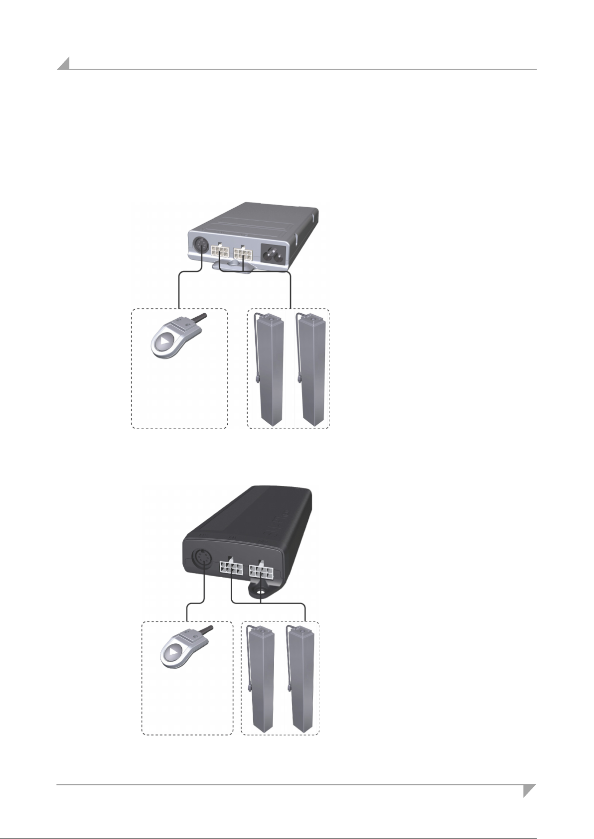
4. Configuration options for the ID21 system
Depending on the particular configuration, the ID21 system can be combined with up to three
lifting columns. The configurations with two and three lifting columns are described below:
Configuration 1:
SMARTeco control unit with one or two ID21 lifting columns and a control keypad
• Install the lifting columns
(see section 5.2, page 26)
• Install the control keypads
(see section 5.3, page 30)
• Install the SMARTeco control
unit (see section 5.4.1, page 37)
• Connect the control keypad and
the lifting columns to the control
unit (see section 5.5.1, page 40)
•
(see section 5.5.1, page 40)
Example:
Motion Assist,
Refer to section 3.3
for other control
keypads.
Configuration 2:
SMARTneo / SMARTneo-pro control unit with one or two ID21 lifting columns and control keypad
22 78438 7.0
Example:
Motion Assist,
Refer to section 3.3
for other control
keypads.
• Install the lifting columns (see
section 5.2, page 26)
• Install the control keypads
(see section 5.3, page 30)
• Install the SMARTneo /
SMARTneo-pro control unit
(see section 5.4.2, 38)
• Connect the control keypad and
the lifting columns to the control
unit (see section 5.5.2, page 41)
•
(see section 5.5.2, page 41)
Page 23
System ID21 Configuration options for the ID21 system
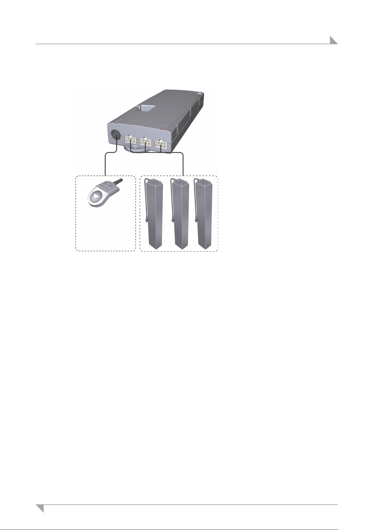
Installation steps:
Connect the power supply cable
Example:
Configuration 3:
COMPACT control unit with one, two or three ID21 lifting columns and a control keypad
• Install the lifting columns
(see section 5.2, page 26)
• Install the control keypads
(see section 5.3, page 30)
• Install the COMPACT control
unit (see section 5.4.3, page 39)
• Connect the control keypad and
the lifting columns to the control
unit (see section 5.5.3, page 42)
•
(see section 5.5.3, page 42)
Motion Assist,
Refer to section 3.3
for other control
keypads.
78438 7.0 23
Page 24
Installation System ID21
5. Installation
5.1 Safety notices to observe during installation
Basic safety rules must be followed in order to ensure that the end product can be continually
operated in a safe manner. These rules must be observed while using the end product and
while installing the SMART/COMPACT control unit, the control keypad, the ID21 lifting columns, and the slave drive in the end product.
Avoiding electrical faults
Be sure to consider the length of the power cord when designing the dimensions for your end
product in order to minimize the associated risks.
Routing the electrical cables
When routing the cables, be sure that:
• the cables cannot get jammed,
• no mechanical load (such as pulling, pushing or bending) will be put on the cables, and
• the cables cannot be damaged in any way.
Fasten all cables using sufficient strain relief and kink prevention methods.
5.1.1 Reliability
The safety and reliability of the end product containing DewertOkin components can be ensured by using the proper construction methods as described below.
Overheating
A thermal monitor switches the SMART/COMPACT control unit off if it overheats.
CAUTION
The SMART/COMPACT control unit is equipped with a thermal monitor (circuit breaker) that triggers when the unit overheats. If the temperature control has triggered, remove the control unit
from the power supply, allow it to rest for 20 to 30 minutes and try again. If the control unit still
does not function, please contact your supplier or sales agent.
Avoiding fatigue fractures
• Install the lifting column in the end product so that it is properly aligned. This will help pre-
vent shear stress.
• Do not position the lifting column at a slanted angle when installing it in the end product. A
slanted angle between the intended direction of movement of the end product and the lifting column's direction will create shear stress and could lead to a fatigue fracture.
24 78438 7.0
Page 25
System ID21 Installation
Avoiding a pinching hazard
When designing your product, you should take the lifting column's adjustment movement into
account with passive safety mechanisms and with the appropriate safety notices in your operating instructions.
• Installation methods for ensuring passive safety: Install the ID21 lifting column so that none
of the positions where shear and pinch hazards exist are accessible externally.
Make sure that your operating instructions inform the user of these safety points.
Structural modifications and improper installation which do not follow the installation steps or
the safety instructions found in these installation instructions may result in serious injuries to
users (e.g. crushing injuries). Structural modifications may only be made after consulting with
DewertOkin and receiving our consent. Follow all instructions from DewertOkin, especially
those found in these installation instructions.
NOTICE
Compliance with the intended usage and other regulations
Any further processing of the products that contradicts the proper and intended usage is forbidden.
The manufacturer or installer of the end product must ensure that all legal and regulatory requirements regarding the end product's manufacture, installation and customer support are followed.
5.1.2 Selecting the tabletop
The DIN Technical Report 147 describes the following information:
• Corner and edge design
• Exterior surfaces
• Surface brightness
• Surface finish
• Min. 3 mm edge radius
This information shall be considered binding when selecting the tabletop.
5.1.3 Ergonomics
The operating instructions that you are creating for the end product must provide instructions for an
ergonomically correct installation where the control keypads are easily accessible and the table is
freely accessible.
5.1.4 Use of the system by the end customer
The operating instructions for the end customer must refer to standards regarding:
• Standards for usage, arrangement of equipment in the working area, the planned activities
and the working postures and positions
• Standards for describing the adjustment mechanisms with instructions for ergonomic ad-
justments
Please refer to the guidelines for the design of screens and office workstations from the German
Trade Association for Printing and Paper Processing (BGI 650).
78438 7.0 25
Page 26
Installation System ID21
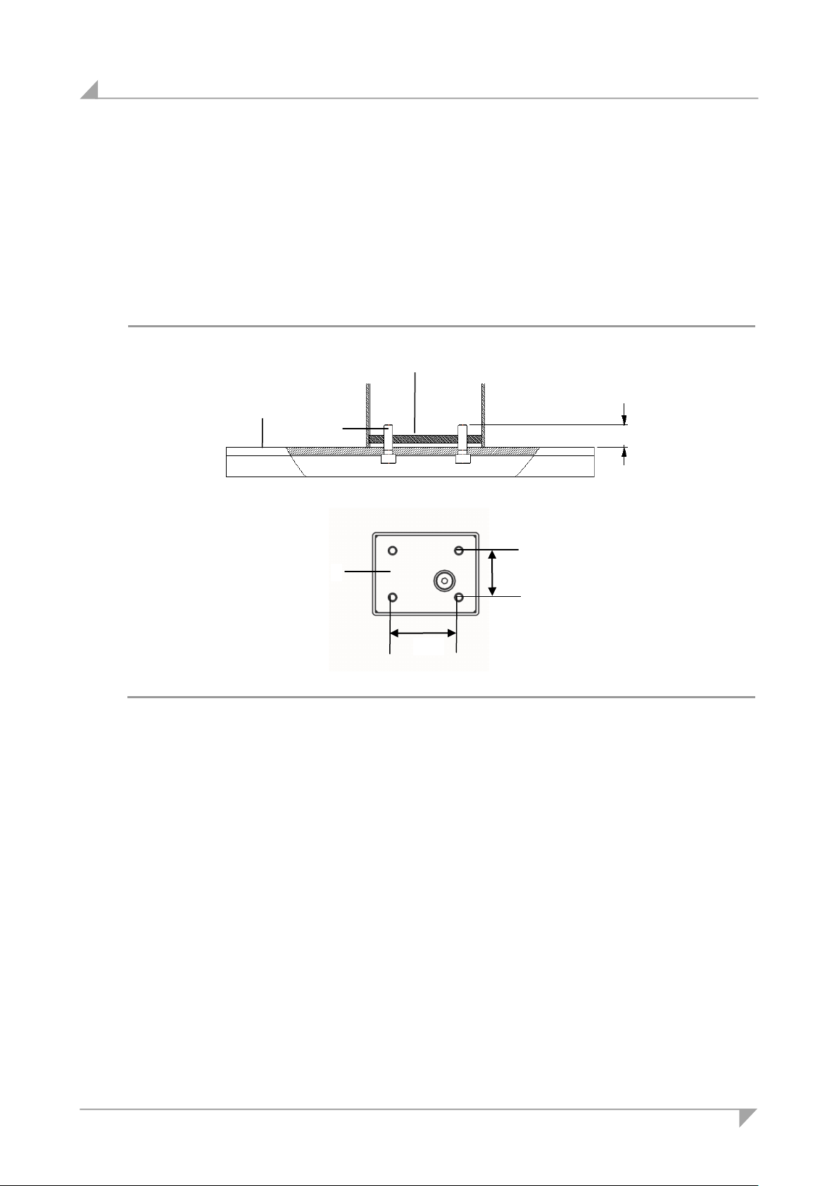
A Base plate
B M6 bolts (8.8)
C Foot of the lifting column
B C A
min. 9, max. 11
50
35
C
5.2 Installing the ID21 lifting columns
Before installing and connecting the ID21 lifting columns, make sure that you are observing all
of the safety notices found in the "Safety notices to observe during installation" section.
5.2.1 Installing the table base
Use M6 bolts (with strength grade 8.8), as shown in Figure17. The tightening torque is 10 Nm.
Figure17 Mounting the table base (dimensions in mm)
26 78438 7.0
Page 27
System ID21 Installation
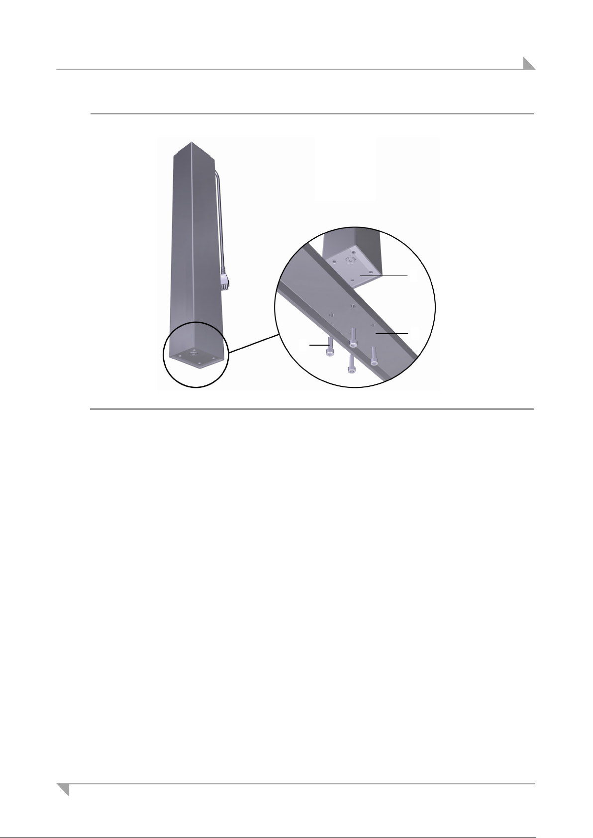
A Base plate
B M6 bolts (8.8)
C Foot of the lifting column
C
A
B
Figure 18 Mounting the table base:
1 Use four screws to attach the table base to the foot end of the ID21 lifting column, as
shown in Figure 18 (tightening torque is 10 Nm). The mounting dimensions are shown in
Figure17.
2 Repeat step 1 with all other lifting columns.
78438 7.0 27
Page 28
Installation System ID21
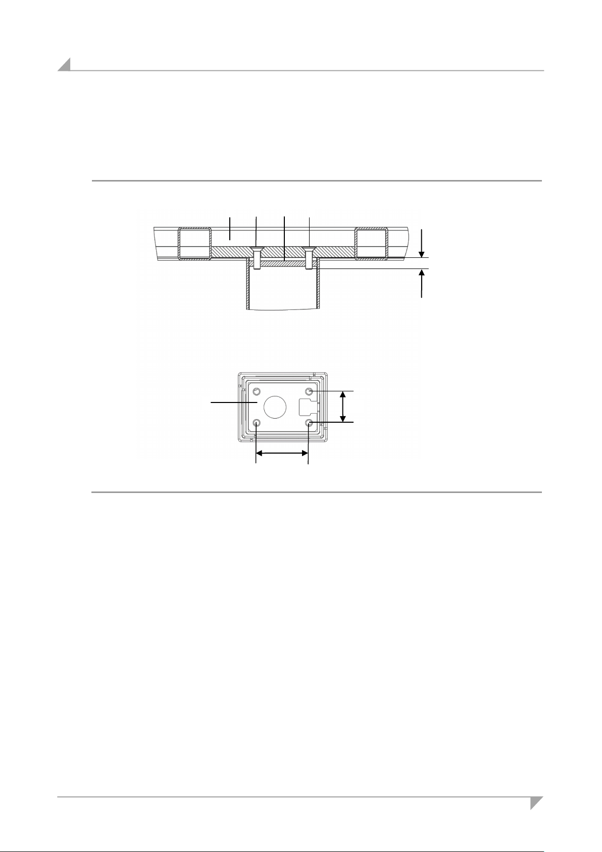
A Table frame
B M6 bolts (8.8)
C Head of the lifting column
min. 9, max. 11
B B C
A
47
28
C
5.2.2 Mounting the table frame
Use M6 bolts (with suitable length and strength grade 8.8), as shown in Figure 19. The tight-
ening torque is 10 Nm.
Figure 19 Mounting the table frame (dimensions in mm)
28 78438 7.0
Page 29
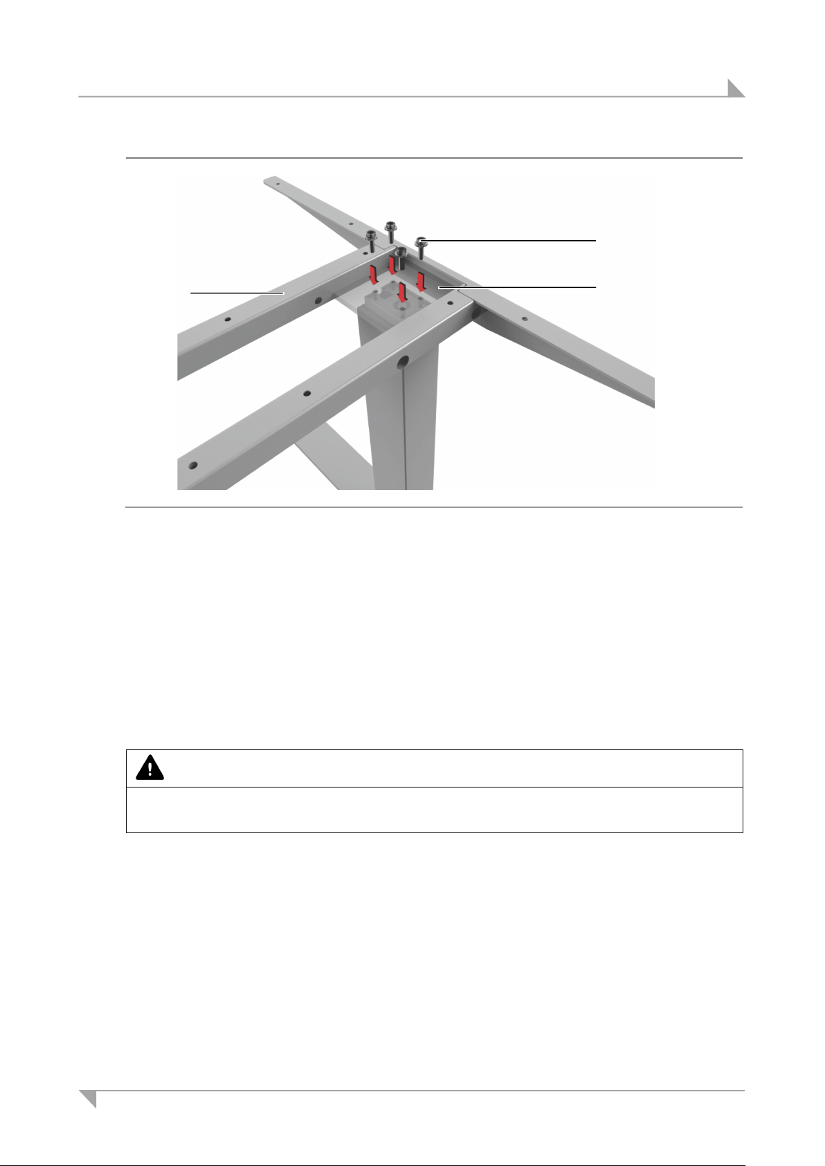
System ID21 Installation
A End product (e.g. a table frame)
B M6 bolts (8.8)
C
C B A
Figure 20 Mounting the table frame
Head of the lifting column
1 Set the table frame so that the holes are over the lifting column. Use four screws to attach
the table frame to the head end of the ID21 lifting column, as shown in Figure 20 (tightening
torque is 10 Nm). The mounting dimensions are shown in Figure 19.
2 Screw the other lifting columns to the table frame.
5.2.3 Dismantling the lifting column
CAUTION
Work on electrical components should be conducted only when the mains power connection for
the control unit is unplugged.
1 Move the table to the starting position, so that the lifting columns are fully retracted.
2 Pull out the control unit's mains power plug!
3 Remove all of the lifting columns' cables from the sockets of the control unit.
4 Remove all lifting columns from the table frame.
78438 7.0 29
Page 30
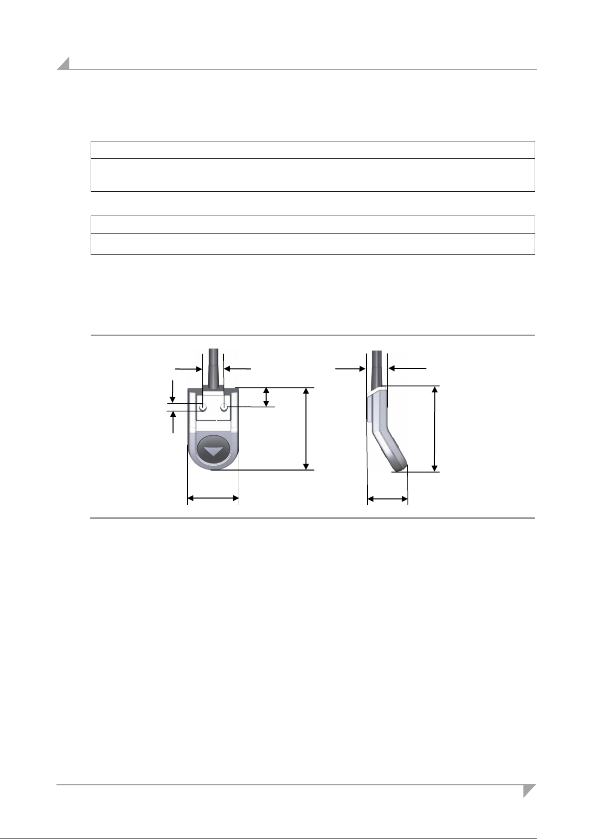
Installation System ID21
32
11.5
13
51
25
12
53
∅ 4,0
5.3 Installing the control keypads
NOTICE
The control keypad must be installed in an ergonomically correct position so that the user can
reach it easily.
NOTICE
Please observe the thickness of the tabletop.
5.3.1 Motion Assist control keypad
Two screws are used to attach the Motion Assist control keypad to the underside of the table
(at the table's front edge), as shown in Figure 22.
Figure 21 Motion Assist control keypad, installation dimensions (in mm)
30 78438 7.0
Page 31
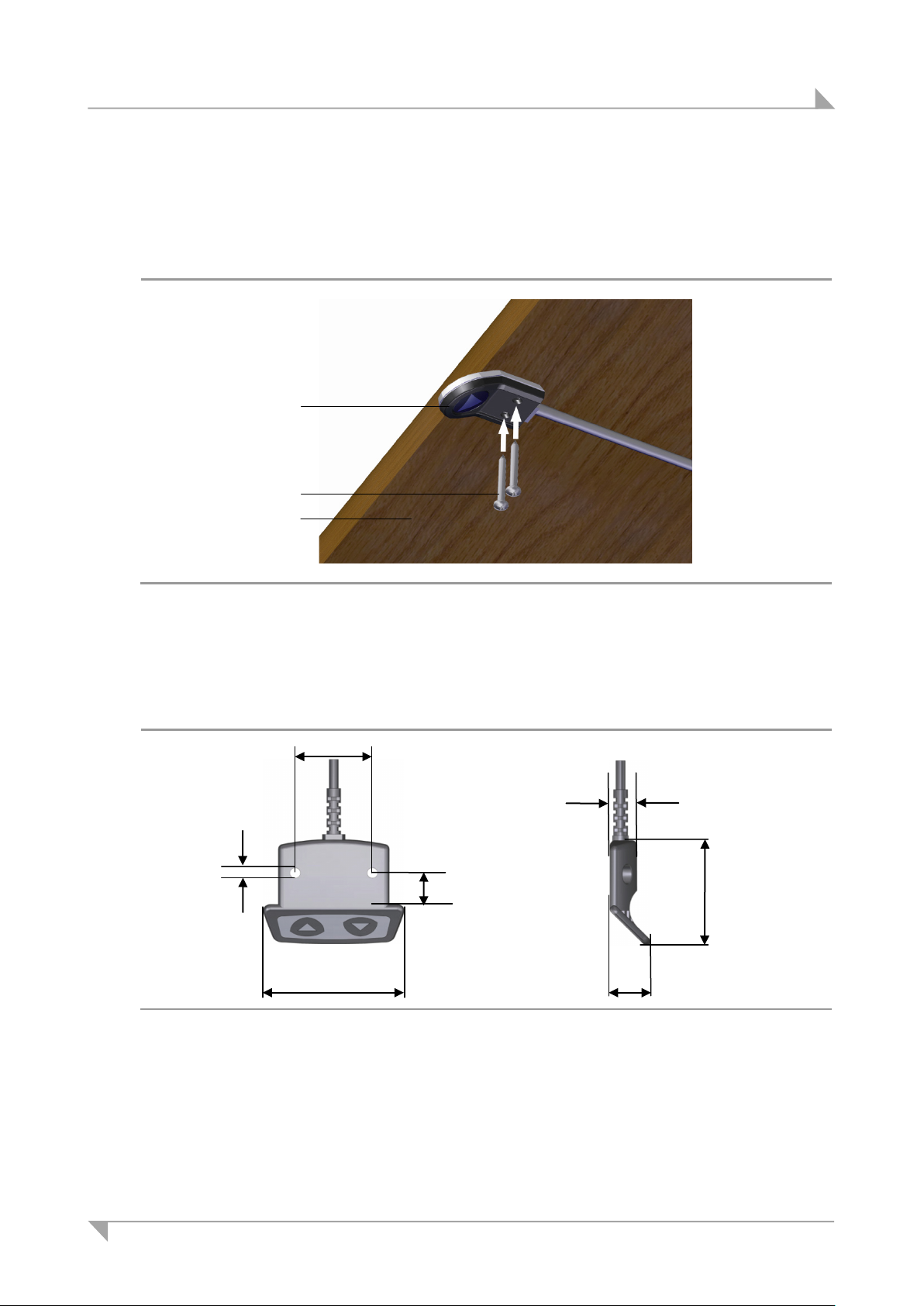
System ID21 Installation
A Motion Assist control keypad
B Screws
C Tabletop
A B C
58.5
13
32
16.5
11
43.5
∅ 4,3
5.3.2 Installing the control keypad to the tabletop
Example: Use screws (B in Figure 22) which meet the requirements of DIN 7981 with Ø 3.9
mm and of suitable length (10 mm plus the screw-in depth into the table), screw head: Ø
7.5 mm.
Figure 22 Example: Mounting the Motion Assist control keypad
5.3.3 HSCO control keypad
Figure 23 HSCO control keypad, installation dimensions (in mm)
78438 7.0 31
Page 32
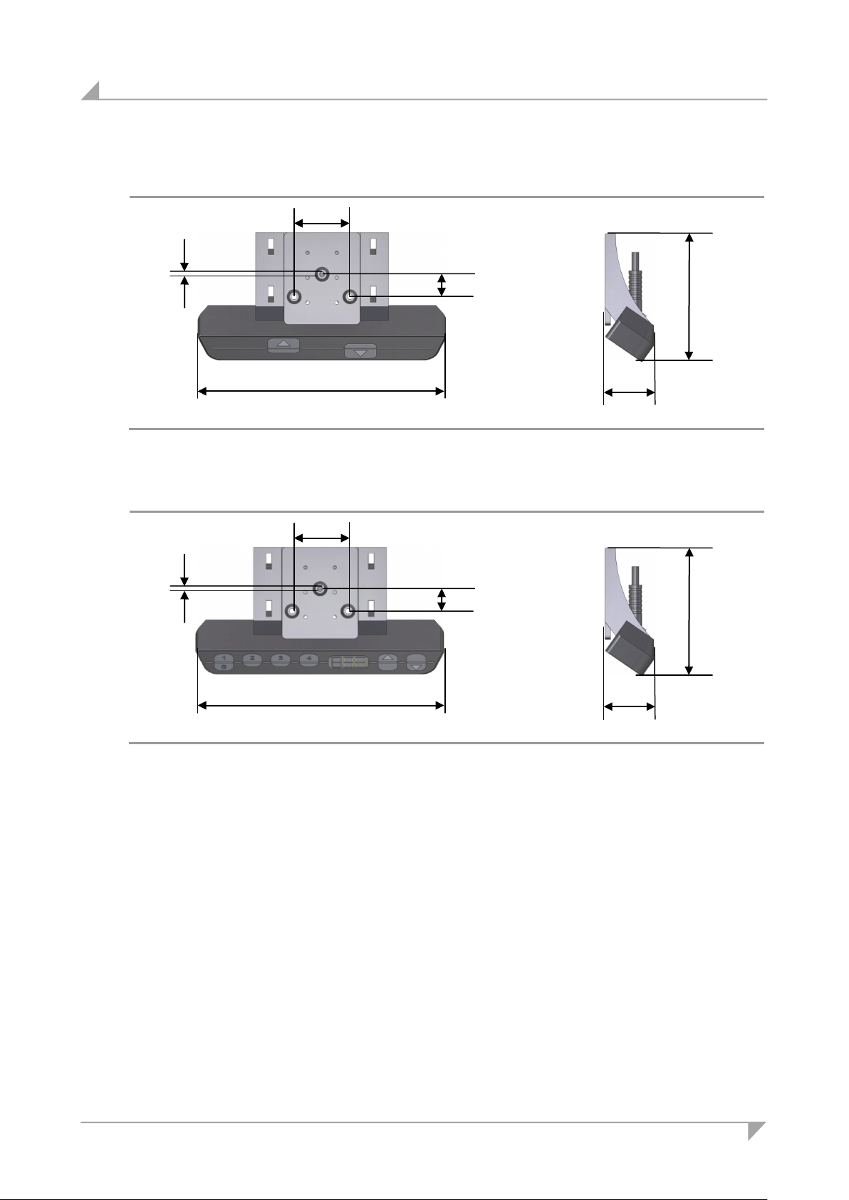
Installation System ID21
135.8
12
30.5
26
69.4
∅ 3,0
135.8
12
30.5
26
69.4
∅ 3,0
5.3.4 HSU Varioline control keypad
Figure 24 HSU Varioline control keypad, installation dimensions (in mm)
5.3.5 HSU control keypad
Figure 25 HSU control keypad, installation dimensions (in mm)
32 78438 7.0
Page 33
System ID21 Installation
129
58
100
9
151
∅ 5,1
68
65
19
30
27
30.5
20.5
142
76
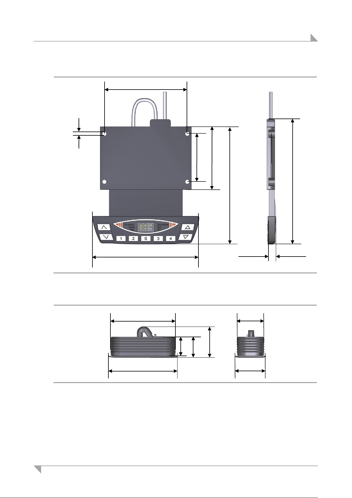
5.3.6 HSF control keypad
Figure 26 HSF control keypad, installation dimensions (in mm)
5.3.7 TOUCHbasic-inlay control keypad
Figure 27 TOUCHbasic-inlay keypad, mounting dimensions (in mm)
78438 7.0 33
Page 34
Installation System ID21
58
22
38
24
52.4
4.7
11
132.5
39
70
34
85.9
5
9
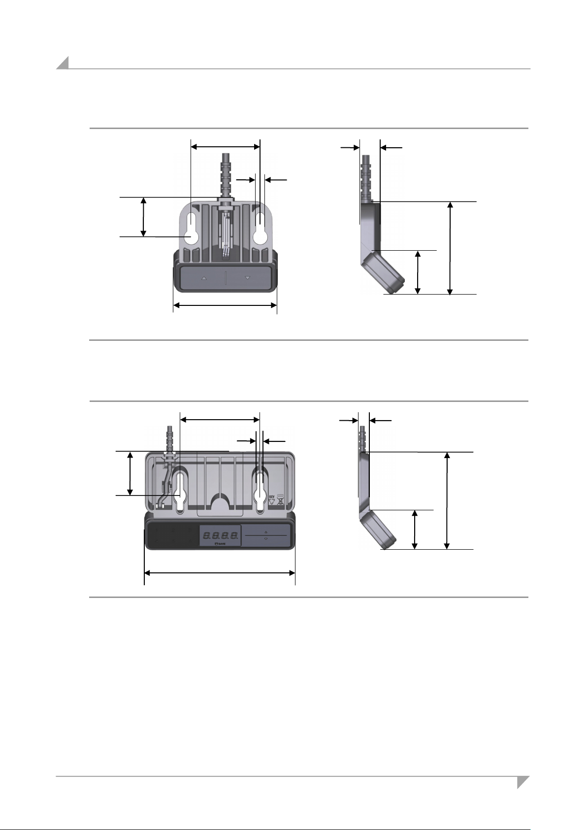
5.3.8 TOUCHbasic-down control keypad
Figure 28 TOUCHbasic-down keypad, mounting dimensions (in mm)
5.3.9 TOUCHfx control keypad
Figure 29 TOUCHfx keypad, mounting dimensions (in mm)
34 78438 7.0
Page 35
System ID21 Installation
170.4
34
75
38.8
150.3
5.5
14.8
95.4
90
18.7
42
37.7
28.3
106
5.5
5.5
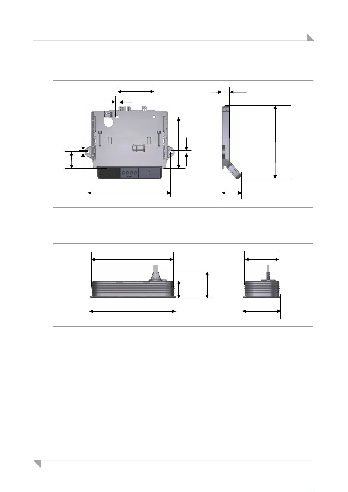
5.3.10 TOUCHdown control keypad
Figure 30 TOUCHdown keypad, mounting dimensions (in mm)
5.3.11 TOUCHinlay control keypad
Figure 31 TOUCHinlay keypad, mounting dimensions (in mm)
78438 7.0 35
Page 36
Installation System ID21
5.4 Installing the SMART/COMPACT control units
NOTICE
Please observe the thickness of the tabletop.
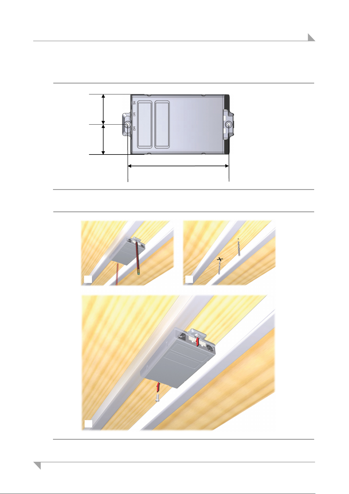
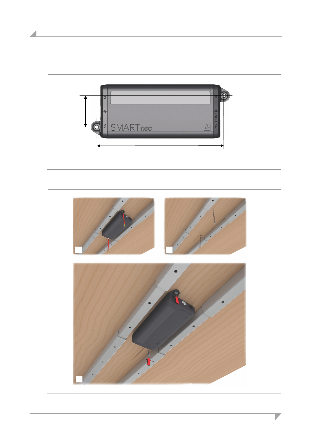
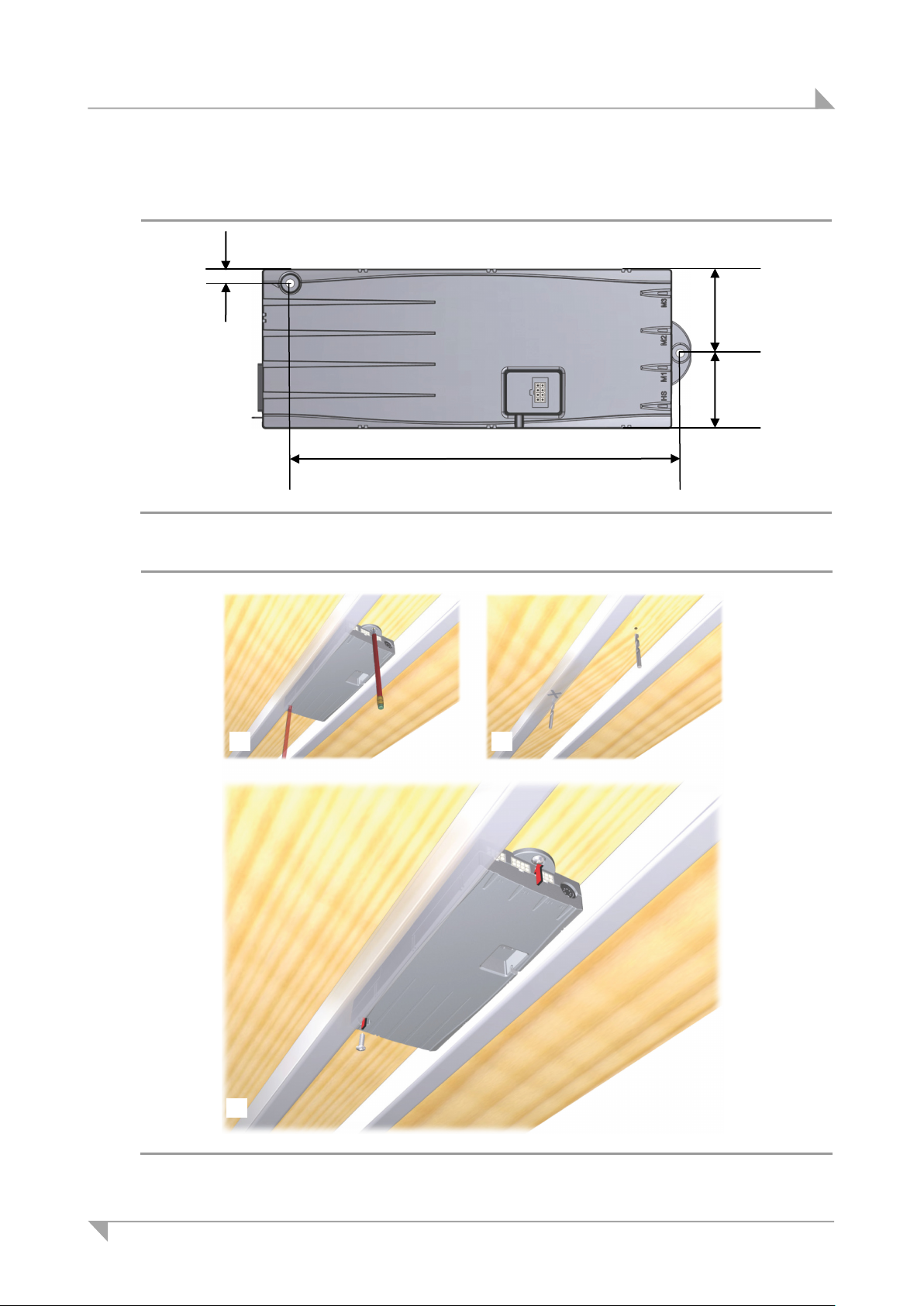
Mount the control unit under the centre of the table. The best installation position is be-
tween the table frames. Be sure to note the length of the connecting cables during the installation.
Use 4.8xL raised-head screws (according to requirements of DIN 7981) with a 9.5 mm
head diameter and of suitable length (2 mm + screw-in depth into the table). Tighten the
screw using a maximum torque of 2 Nm.
CAUTION
You should only install and uninstall the control unit when it is completely disconnected from any
live current!
Install the control unit as shown in Figure 33 (control unit SMARTeco), Figure 35 (control unit
SMARTneo / SMARTneo-pro) or Figure 37 (control unit COMPACT):
1 Mark the drill holes. The drilling dimensions are specified in Figure 32 (control unit SMARTeco),
Figure 34 (control unit SMARTneo / SMARTneo-pro) or Figure 36 (control unit COMPACT).
2 Use a suitable drill to drill the two holes.
3 Screw the control unit onto the tabletop.
4 Route all connecting cables under the tabletop so that they cannot be pinched during the table's
lifting movements.
36 78438 7.0
Page 37
System ID21 Installation
167.9
50.2
50.2 1 2
3
5.4.1 Control unit SMARTeco
Figure 32 Mounting dimensions: SMARTeco control unit (in mm)
Figure 33 Mounting the SMARTeco control unit
78438 7.0 37
Page 38
Installation System ID21
200
49.2
1
2
3
5.4.2 SMARTneo / SMARTneo-pro control unit
Figure 34 Mounting dimensions: SMARTneo / SMARTneo-pro control unit (in mm)
Figure 35 Mounting the SMARTneo / SMARTneo-pro control unit
38 78438 7.0
Page 39
System ID21 Installation
1 2 3
252
51.5
6.5
51.5
5.4.3 COMPACT control unit
Figure 36 Mounting dimensions: COMPACT control unit (in mm)
Figure 37 Mounting the COMPACT control unit
78438 7.0 39
Page 40
Installation System ID21
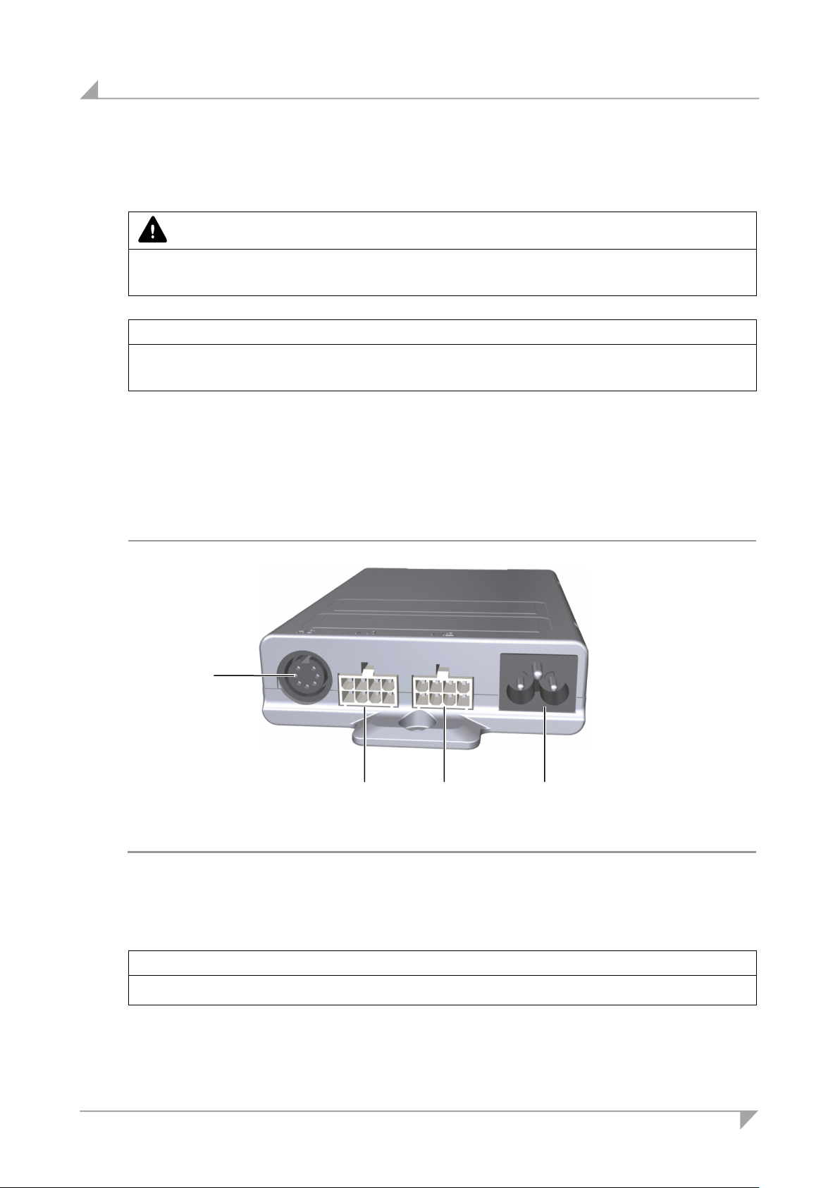
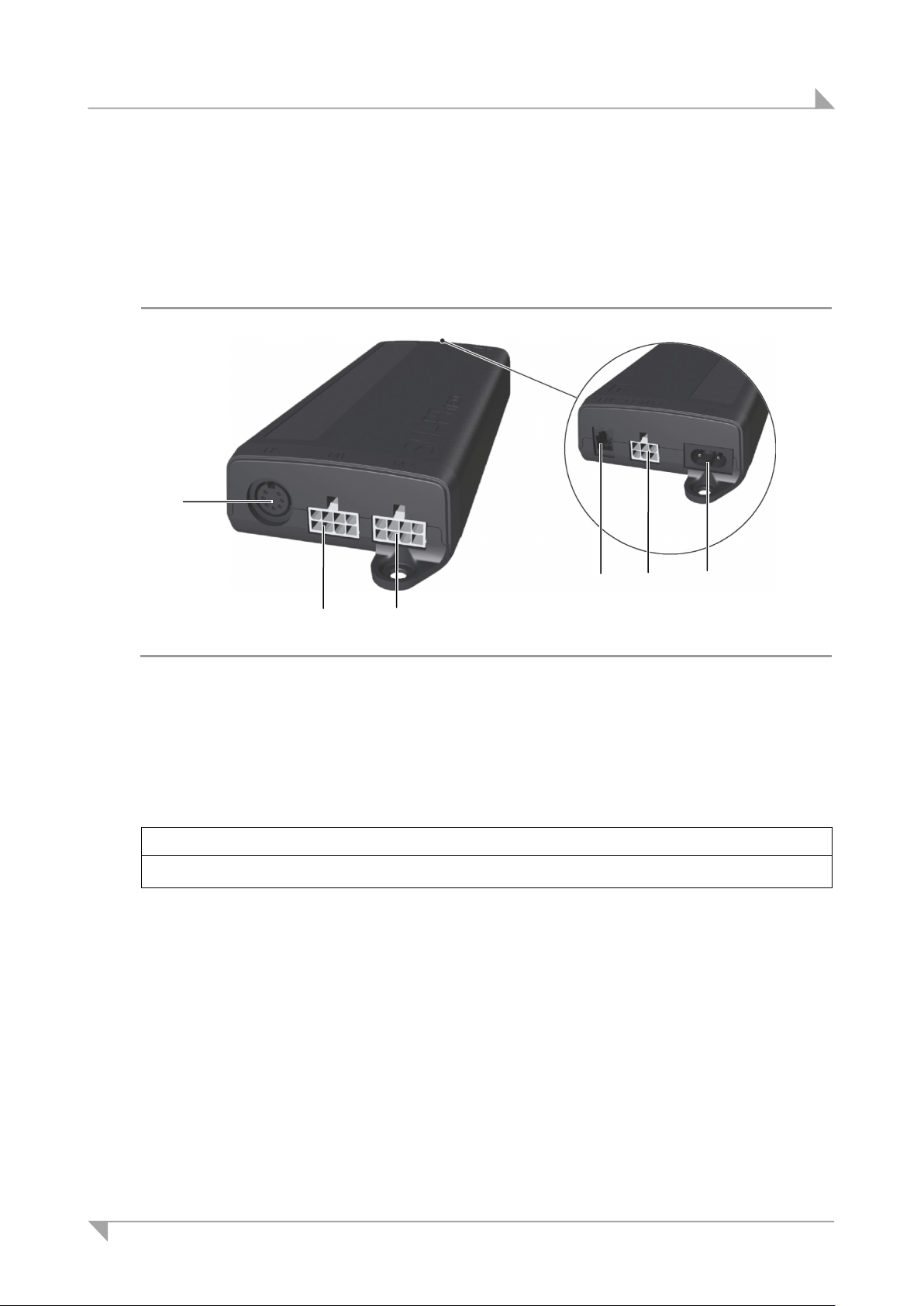
A Connection for the control keypad
B Mains power supply connection
C Connection for the lifting columns
A B B
C
5.5 Electrical connections for the SMART/COMPACT control units
CAUTION
Electrical components should be connected or disconnected only when the power supply cord is
unplugged.
NOTICE
There is a delay after the supply voltage is applied before the device actually turns on. Wait at
least seven seconds before beginning the commissioning.
5.5.1 Connecting the lifting columns and the control keypad to the SMARTeco control unit
The lifting columns and the control keypad are both connected to the front of the SMARTeco
control unit (the unit for adjusting one or two lifting columns). The following illustration shows
the location of these connections.
Figure 38 Connection ports on the SMARTeco control unit: Model used for two lifting columns
NOTICE
Be sure to connect the power cable into the control unit after all other connections are plugged in.
40 78438 7.0
Page 41
System ID21 Installation
A Connection for the control keypad
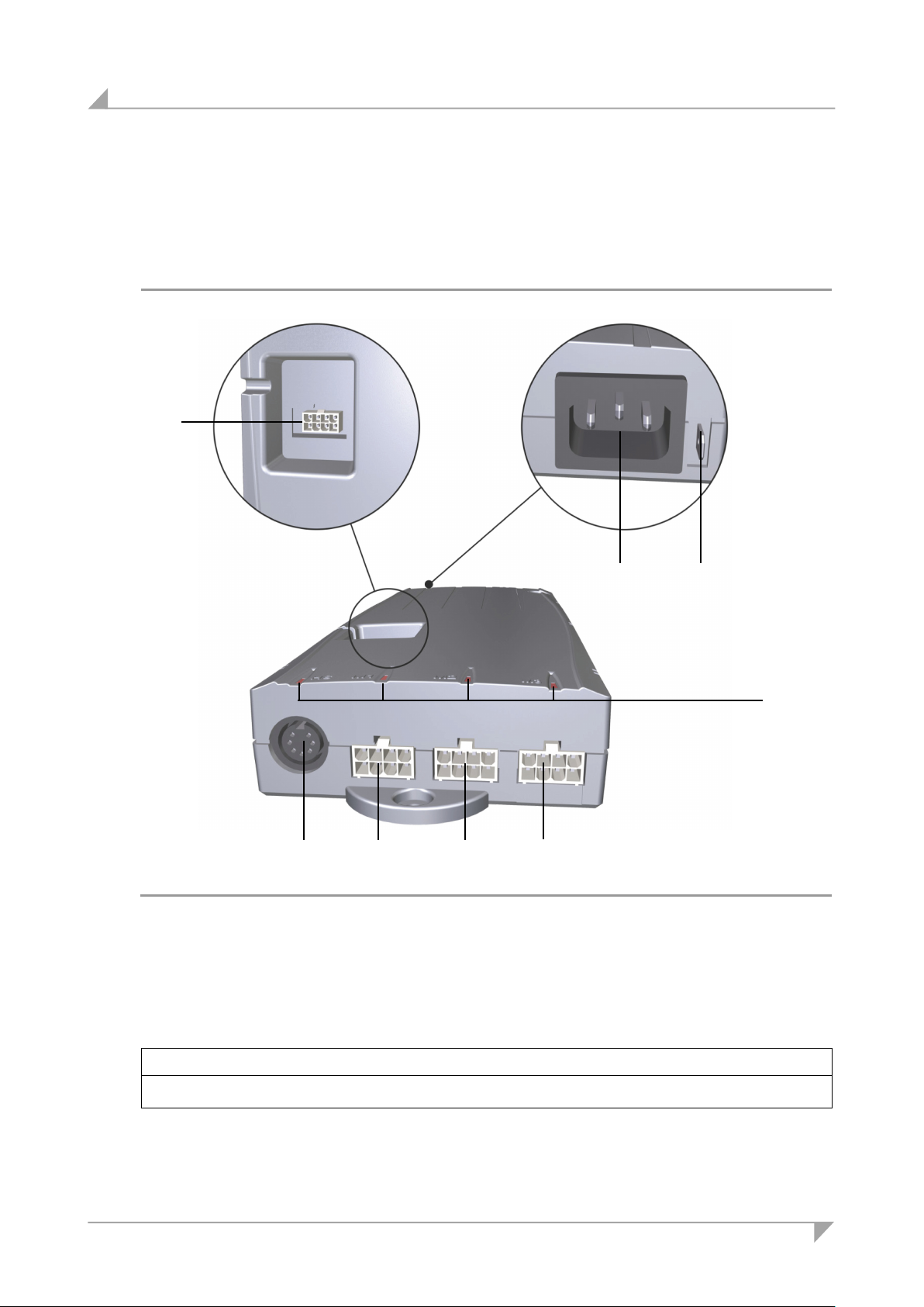
B Connection for the lifting columns
C
D
E Mains power supply connection
A B B C D
E
5.5.2 Connecting the lifting columns and the control keypad to the SMARTneo / SMARTneopro control unit
The lifting columns and the control keypad are both connected to the front of the SMARTneo /
SMARTneo-pro control unit (the unit for adjusting one or two lifting columns). The following illustration shows the location of these connections.
Figure 39 Connections on the SMARTneo / SMARTneo-pro control unit: Model used for
two lifting columns
Sensor connection (only for SMARTneo-pro)
NOTICE
Be sure to connect the power cable into the control unit after all other connections are plugged in.
Cascading connection
78438 7.0 41
Page 42
Installation System ID21
A Connection for the control keypad
B Mains power supply connection
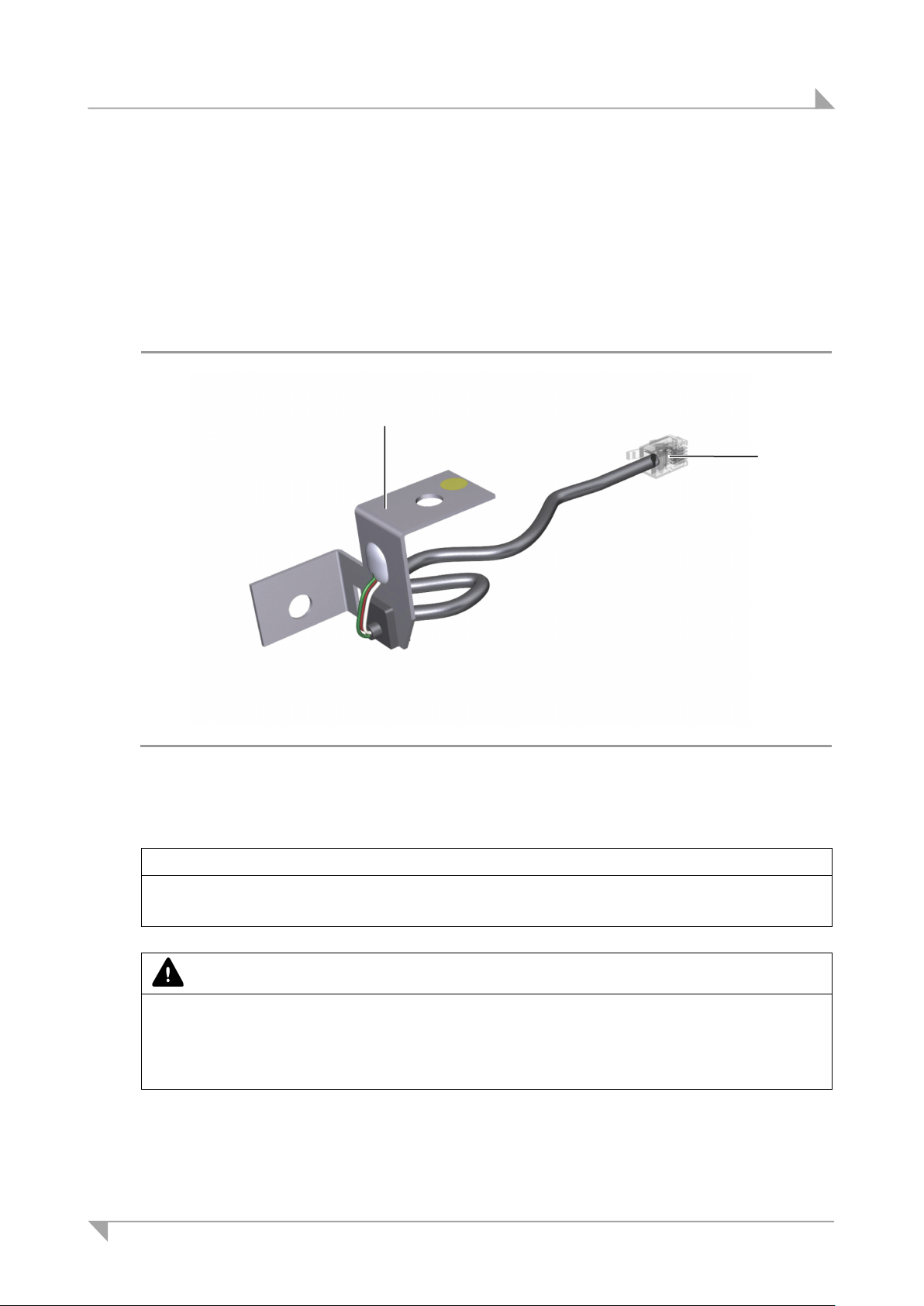
C Connection for the lifting columns
D Status LEDs
E
F
B
F
C
C
C
A
D
5.5.3 Connecting the lifting columns and the control keypad to the COMPACT control unit
The lifting columns and the control keypad are both connected to the front of the COMPACT
control unit. A sensor or a second control unit can optionally be connected with a cable to the
top of the control unit.
E
Figure 40 Connection ports on the COMPACT control unit
Sensor connection / cascade connection
NOTICE
Be sure to connect the power cable into the control unit after all other connections are plugged in.
42 78438 7.0
Protective earth connection
Page 43
System ID21 Installation
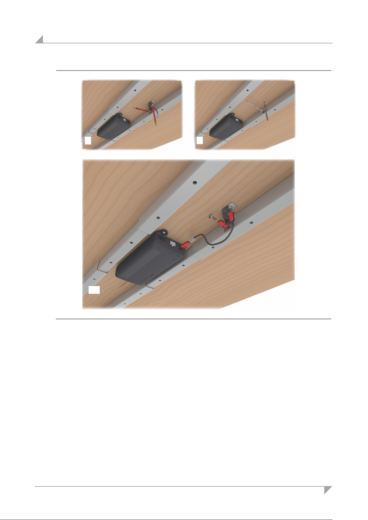
A Sensor
B Connecting cable (connection to the
B
A
5.6 Mounting the sensor unit
5.6.1 SMARTneo-pro control unit
The SMARTneo-pro control unit can be equipped with a protective mechanism. For this purpose,
the sensor is mounted under the table top between the table frames.
The sensor is attached to both the table frame and the tabletop. The contact point with the
tabletop is marked with a yellow dot, as shown in Figure 41.
Figure 41 Sensor
SMARTneo-pro control unit)
NOTICE
This protective mechanism only works when the sensor is correctly installed. Make sure that the
side of the sensor marked with a yellow dot is facing the tabletop.
CAUTION
• You should only install and remove the sensor when it is completely disconnected from any
live current!
• This safety mechanism is not effective unless the drilled holes are aligned exactly with each
other. Personal injury and property damage can result from improper alignment.
The screws are not included in our delivery.
78438 7.0 43
Page 44
Installation System ID21
2
3-4
1
Figure 42 Mounting and connecting the sensor to the SMARTneo-pro control unit
Mount the sensor bracket marked with the yellow dot to the underside of the tabletop. Mount
the second bracket to the table frame (as shown in Figure 42).
Before mounting the sensor, make sure that the cables are long enough to reach the sen-
sor in that position. Also make sure that the cables are routed so that they cannot be
pinched during the up and down movements.
1 If no holes are pre-drilled, mark the drill holes for mounting the sensor (on underside of table-
top and on table frame).
2 Drill the holes for mounting the sensor.
44 78438 7.0
Page 45
System ID21 Installation
CAUTION
Observe the following information in order to ensure that the safety mechanism functions properly:
• If the screws are not tightened properly, the safety mechanism will not function effectively.
• Use both screws.
• Take appropriate measures to prevent the screws from loosening during operations: loose
screws will prevent the safety mechanism from functioning effectively.
• The connected cables may be neither too slack nor too tight.
3 Screw on the sensor. Pay attention to the correct positioning (the side with the yellow dot should
be mounted to the underside of the tabletop). Observe the recommended torques:
• Mount to table frame: 3 Nm,
• Mount to tabletop: 2 – 2.5 Nm (depending on the type of wood in use).
CAUTION
In order to ensure the effectiveness of the safety mechanism, note the following when connecting
the processor:
• If only one sensor is being connected, it should be connected to the socket number 1.
• If a second sensor is being connected to the processor, connect it to the other available
socket.
• Only one sensor may be connected to the processor when you are cascading several control
units! This one sensor should then be connected to the socket number 1.
4 Connect the cable of the sensor unit to the SMARTneo-pro control unit (see Figure 42).
78438 7.0 45
Page 46
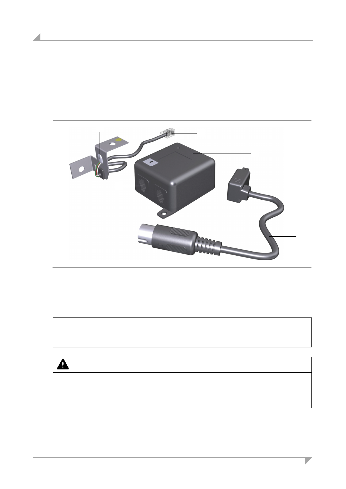
Installation System ID21
A Sensor
B Connecting cable (for connection to processor)
C Connection for the sensor cable
D Processor
E Connecting cable for control unit
D
C
E
B
A
5.6.2 COMPACT control unit
The COMPACT control unit can be equipped with a protective mechanism. A sensor unit (sensor
and processor) can be mounted under the tabletop between the table frames.
The sensor is attached to both the table frame and the tabletop. The contact point with the
tabletop is marked with a yellow dot, as shown in Figure 43.
Figure 43 Sensor unit
NOTICE
This protective mechanism only works when the sensor is correctly installed. Make sure that the
side of the sensor marked with a yellow dot is facing the tabletop.
CAUTION
• You should only install and remove the sensor when it is completely disconnected from any
live current!
• This safety mechanism is not effective unless the drilled holes are aligned exactly with each
other. Personal injury and property damage can result from improper alignment.
The screws are not included in our delivery.
46 78438 7.0
Page 47
System ID21 Installation
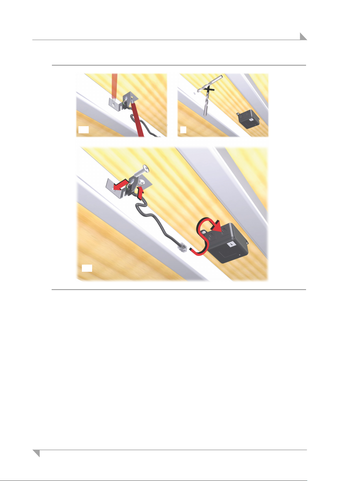
1-2
3
4-5
Figure 44 Mounting the sensor unit (sensor and processor)
Mount the sensor bracket marked with the yellow dot to the underside of the tabletop. Mount
the second bracket to the table frame (as shown in Figure 44).
Before mounting the sensor, make sure that the cables are long enough to reach the sen-
sor in that position. Also make sure that the cables are routed so that they cannot be
pinched during the up and down movements.
1 Mark the drill holes used for mounting the processor. Drill pilot holes and then screw the
processor on the underside of the tabletop so that it is in the vicinity of the control unit.
2 If no holes are pre-drilled, mark the drill holes for mounting the sensor (on underside of ta-
bletop and on table frame).
3 Drill the holes for mounting the sensor.
78438 7.0 47
Page 48
Installation System ID21
CAUTION
Observe the following information in order to ensure that the safety mechanism functions properly:
• If the screws are not tightened properly, the safety mechanism will not function effectively.
• Use both screws.
• Take appropriate measures to prevent the screws from loosening during operations: loose
screws will prevent the safety mechanism from functioning effectively.
• The connected cables may be neither too slack nor too tight.
4 Screw on the sensor. Pay attention to the correct positioning (the side with the yellow dot should
be mounted to the underside of the tabletop). Observe the recommended torques:
• Mount to table frame: 3 Nm,
• Mount to tabletop: 2 – 2.5 Nm (depending on the type of wood in use).
CAUTION
In order to ensure the effectiveness of the safety mechanism, note the following when connecting
the processor:
• If only one sensor is being connected, it should be connected to the socket number 1.
• If a second sensor is being connected to the processor, connect it to the other available
socket.
• Only one sensor may be connected to the processor when you are cascading several control
units! This one sensor should then be connected to the socket number 1.
5 Connect the sensor's cable to the processor.
6 Connect the processor's cable to the COMPACT control unit (see Figure 40).
48 78438 7.0
Page 49
System ID21 Installation
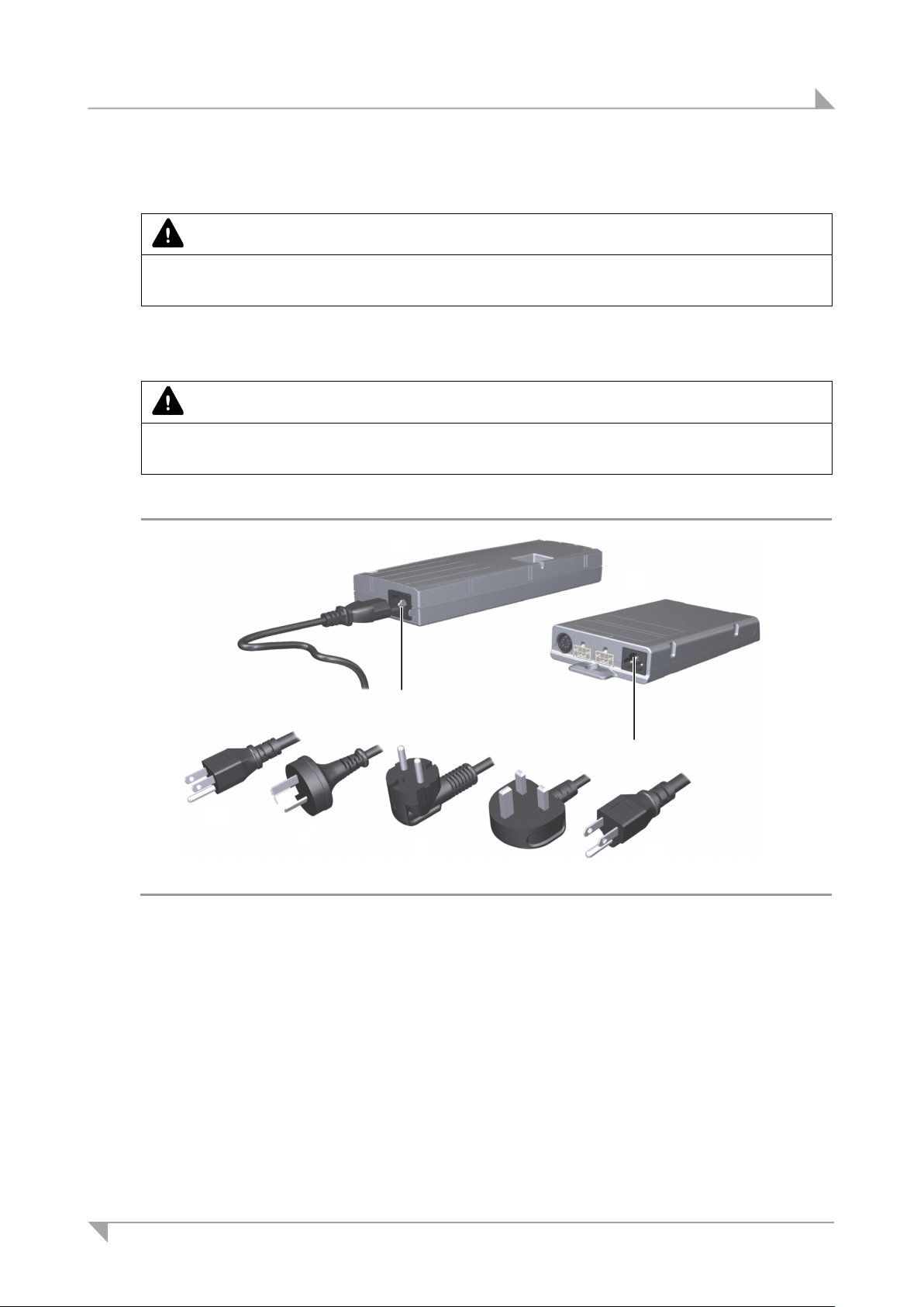
A COMPACT control unit
B Control unit SMARTeco
C Mains power supply connection
D Power plug (USA)
E Power plug (Australia)
F Power plug (EURO flat plug)
G
H
A
D
E
G
F
H
B C C
5.6.3 Mains power supply for the SMART/COMPACT control units
CAUTION
Please follow these operating instructions carefully. You could be injured by fire or electrical shock
if you do not follow these assembly instructions.
The appropriate power cord is included, depending on the regional version (USA, continental
Europe, the UK, Japan or Australia).
CAUTION
Only use the proper power cable that is permitted in your country. Be sure to use the correctly
shaped plug, as shown in the following illustration.
SMARTeco and COMPACT
Figure 45 Variants of the SMARTeco and COMPACT mains power cable
Power plug (United Kingdom)
78438 7.0 49
Power plug (Japan)
Page 50
Installation System ID21
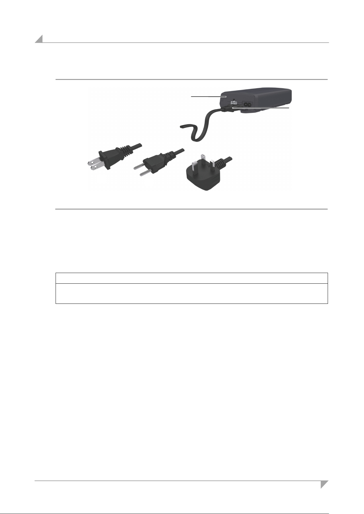
C Power plug (EURO flat plug)
D Power plug (United Kingdom)
E Power plug (USA)
C
D E B
A
SMARTneo / SMARTneo-pro
Figure 46 Variants of the SMARTneo / SMARTneo-pro power supply cable
A SMARTneo control unit (example) B Mains power supply connection
After plugging the power plug into the power outlet,
NOTICE
There is a delay after the supply voltage is applied before the device actually turns on. Wait at
least seven seconds before beginning the commissioning.
You will need to carry out a reset movement on the control unit (see section 6.1 on page 51)
after the initial commissioning.
50 78438 7.0
Page 51
System ID21 Initial commissioning
6. Initial commissioning
CAUTION
The ID21 system must first be fully installed (see chapters 4 and 5) and all components must be
connected before you can carry out the initial commissioning.
It is not possible to connect a second control unit or additional lifting columns later.
NOTICE
You must carry out a reset (refer to section 6.1) after you disconnect the cable that connects a
component (drive, handset, etc.) to the control unit for the ID21 system.
6.1 Reset during initial commissioning and after the removal of connecting cables
CAUTION
Danger of pinching/crushing injuries!
No system-based safety mechanism is enabled during the reset process.
1 Connect the power cable to the control unit's power connection.
2 Insert the mains power plug into a power outlet.
3 Press and hold the key (adjusting downward) until the tabletop moves all the way down.
4 Press the key for at least five seconds longer.
5 The lifting column moves briefly downwards, then immediately upwards and then comes to
a stop.
6 The reset is now finished. You can now press the corresponding key to raise or lower the
lifting columns.
78438 7.0 51
Page 52
Notes for operation System ID21
7. Notes for operation
These installation instructions do not contain all information required for the safe operation of
the end product. They only describe the installation and operation of the drive as components
(as defined in the Machinery Directive as a "partially assembled piece of machinery").
7.1 General information
CAUTION
Danger of pinching/crushing injuries!
Make sure that there are no persons (especially children) or objects located in the range of
movement while the table is moving.
Delayed start-up
Note that this device switches on with a slight delay after the power cord is plugged in and
voltage is applied. Wait at least seven seconds before beginning the commissioning.
Power-on time / intermittent operations
NOTICE
The SMART/COMPACT control units have been designed for intermittent operations. Intermittent
operation is an operational mode where the drive must pause after a specified maximum period of
operation (power-on time). This protects the drive from overheating. Extreme overheating can
cause a malfunction.
The ratings plate specifies the maximum power-on time and the required pause intervals.
Avoiding electrical risks
CAUTION
Make sure that all live (current-carrying) parts of the drive system and power supply cannot be
touched. In particular, be sure that unused power and control unit connections are covered adequately.
52 78438 7.0
Page 53
System ID21 Notes for operation
Reducing the risk of overheating with the thermal monitor
CAUTION
The SMART/COMPACT control unit is equipped with a thermal monitor (circuit breaker) that triggers when the unit overheats. If the temperature control has triggered, remove the control unit
from the power supply, allow it to rest for 20 to 30 minutes and try again. If the control unit still
does not function, please contact your supplier or sales agent.
Shutting down the ID21 system in an emergency
Pull out the power plug in order to shut off the ID21 system. The power plug must always be
accessible during operations so that emergency shut-off is possible.
Avoiding cable damage
Be sure that your operating instructions inform the user about the possible cable risks.
NOTICE
The cables (in particular the electrical connection for the drives and the power supply cable for the
drive system) must not be squashed or crushed. In order to prevent damage to the drive, no mechanical strain should be placed on the cables.
78438 7.0 53
Page 54
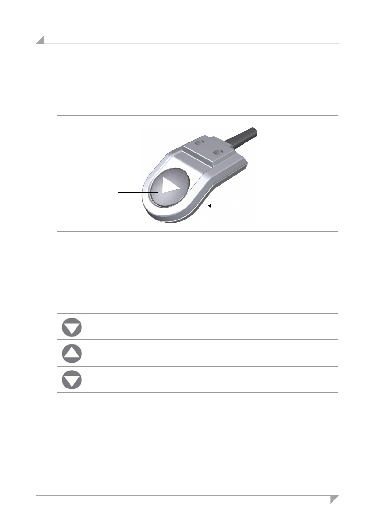
Operating the control keypads System ID21
A Key for adjusting downwards
D Key for adjusting upwards: located on the
Button
Function
D
8. Operating the control keypads
8.1 Functions of the Motion Assist control keypad
A
Figure 47 Motion Assist control keypad
underside of the control keypad
8.1.1 Key assignments for the Motion Assist control keypad
Adjusting downwards
Adjusting upwards
For carrying out the reset motion after a malfunction
Press the key on the control keypad to raise or lower the table. Keep pressing the key until
the desired height of the table is reached.
(refer to 6.1).
54 78438 7.0
Page 55
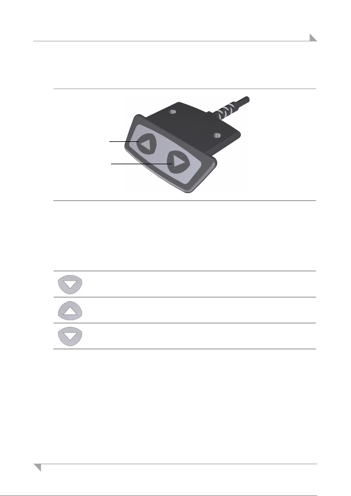
System ID21 Operating the control keypads
A
Button
Function
D
A
8.2 Functions of the HSCO control keypad
Figure 48 HSCO control keypad
Key for adjusting downwards
8.2.1 Key assignments for the HSCO control keypad
D Key for adjusting upwards
Adjusting downwards
Adjusting upwards
For carrying out the reset motion after a malfunction
Press the key on the control keypad to raise or lower the table. Keep pressing the key until
the desired height of the table is reached.
(refer to 6.1).
78438 7.0 55
Page 56
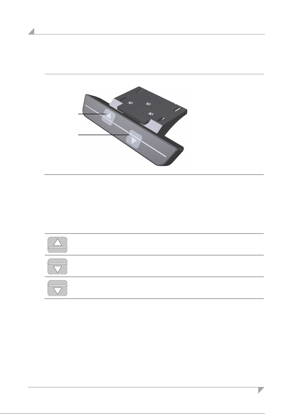
Operating the control keypads System ID21
A Key for adjusting downwards
Button
Function
D A
8.3 Functions of the HSU Varioline control keypad
Figure 49 HSU Varioline control keypad
D Key for adjusting upwards
8.3.1 Key assignments for the HSU Varioline control keypad
Adjusting upwards
Adjusting downwards
For carrying out the reset motion after a malfunction
Press the key on the control keypad to raise or lower the table. Keep pressing the key until
the desired height of the table is reached.
(refer to 6.1).
56 78438 7.0
Page 57
System ID21 Operating the control keypads
A Key for adjusting downwards
D Key for adjusting downwards
E Memory key 1
F Memory key 2
G
H
I Display
J Save key S
Key / indicator
Function
Key / indicator
Function
E
D
A
I H G F J
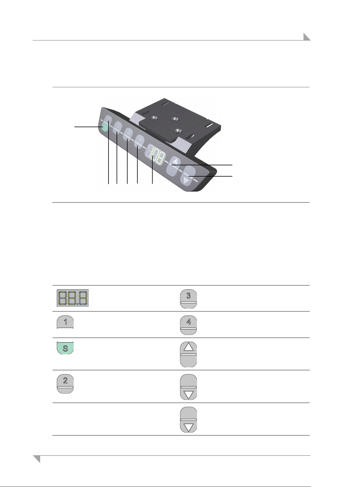
8.4 Functions of the HSU control keypad
Figure 50 HSU control keypad
Memory key 3
8.4.1 Key assignments for the HSU control keypad
Display
Memory key 1
Save key S
Memory key 4
Memory key 3
Memory key 4
Adjusting upwards
78438 7.0 57
Memory key 2
Adjusting downwards
For carrying out the reset motion after a malfunction (refer
to 6.1).
Page 58
Operating the control keypads System ID21
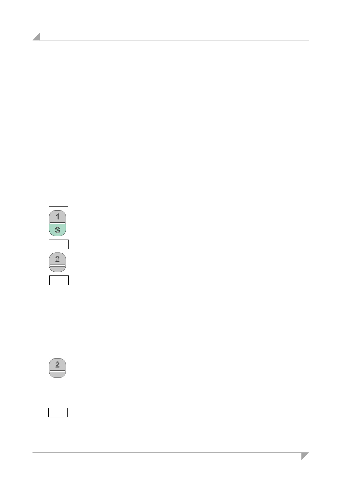
1
3 Press the desired memory key (e.g. 2).
4 The set table position is now saved for the selected memory key.
1 Press and hold the memory key that corresponds to the desired table po-
2 Release the key when the table has reached the saved position.
The display on the HSU control keypad is a three-character positional and information dis-
play.
Using the keys for upwards or downwards adjustments: Press and hold the corresponding
key until the desired position is reached.
8.4.2 Advanced functions
Saving a position
Any table position can be saved using this function.
When the control unit is turned on for the first time, all positions are equal to the smallest
table position (the lower end position).
Only one table position can be stored per memory key.
To save a position, proceed as follows:
073
5 -
5 2
Adjusting the table to a saved height position
This function allows you to set the table to a saved table position.
Move the table to the position that you want to save.
The position is shown on the display (e.g. 73 cm).
2 Press the green Save key.
S - is now shown on the display.
S 2 is shown on the display.
A double-click noise can then be heard. After about 2 seconds, the saved
table position is displayed.
sition (e.g. position 2).
073
58 78438 7.0
The table will move as long as the memory key is pressed. If you release
this key before the saved position is reached, the table will stop before it
reaches this position.
The current (saved) position is shown on the display.
Page 59
System ID21 Operating the control keypads
Key / indicator
Function
Key / indicator
Function
Display and LED indi-
For carrying out the reset mo-
E
D A H G J F
I
L
K
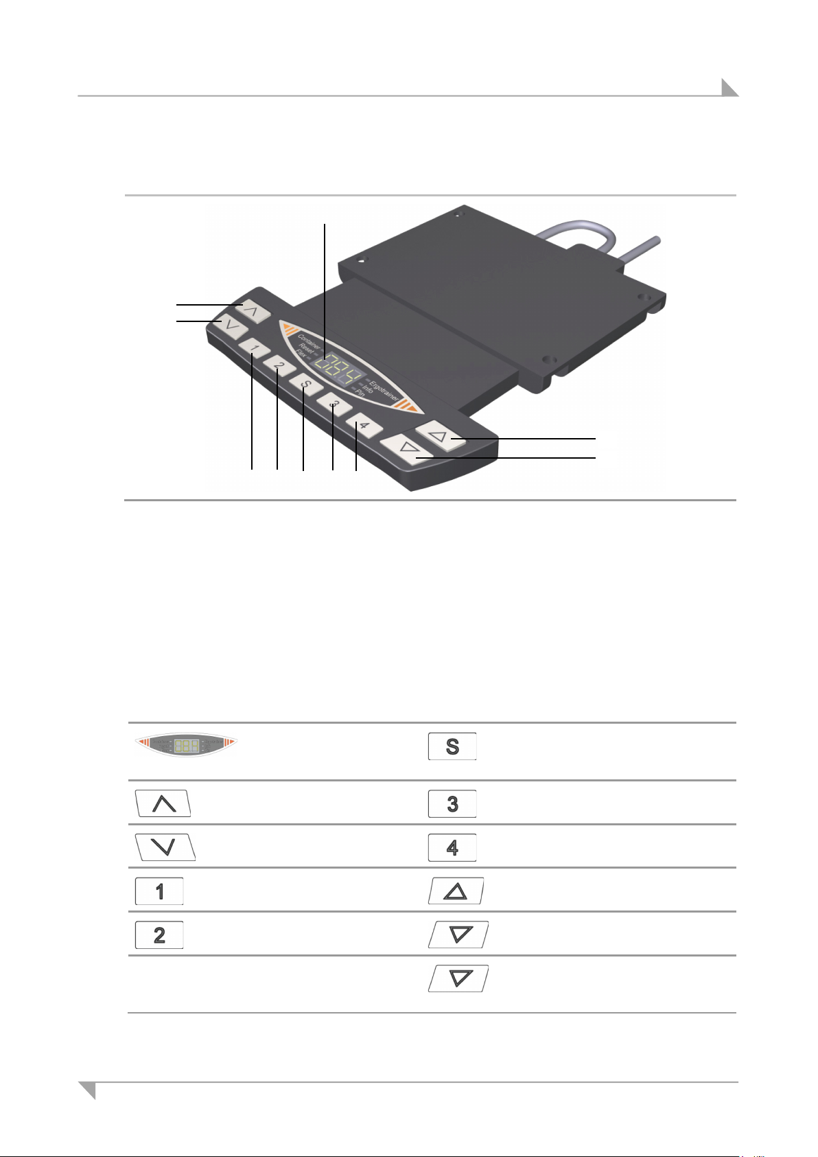
8.5 Functions of the HSF control keypad
Figure 51 HSF control keypad
A Key for adjusting downwards D Key for adjusting upwards
E Memory key 1
G Memory key 3
I Display
K Motor group 2, adjust downwards
8.5.1 Key assignments for the HSF keypad
cators (refer to section
8.5.2)
Motor group 2, adjust
upwards
Motor group 2, adjust
downwards
Memory key 1
Memory key 2
F Memory key 2
H Memory key 4
J Save key S
L Motor group 2, adjust upwards
Memory key
Memory key 3
Memory key 4
Adjusting upwards
Adjusting downwards
tion after a malfunction (refer
to 6.1).
Using the keys for upwards or downwards adjustments: Press and hold the corresponding
key until the desired position is reached.
78438 7.0 59
Page 60
Operating the control keypads System ID21
LED
Function
This LED indicates that the container stop is enabled. (Depend-
This LED indicates that a control unit reset is being carried out.
This LED indicates that the Flex function is enabled. (Depending
This LED indicates that important information is displayed on the
This LED indicates that the PIN CODE function is enabled.
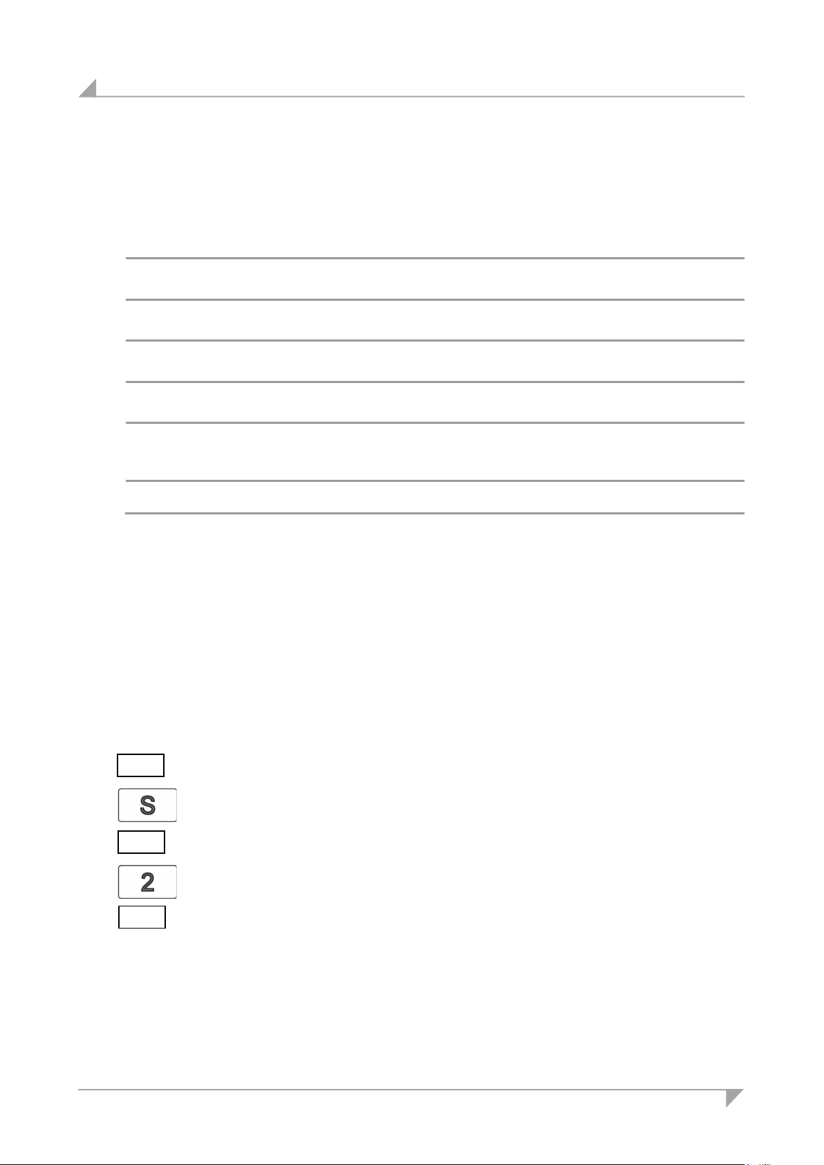
1 Move the table to the position that you want to save.
2 Press the Save key.
3 Press the desired memory key (e.g. 2).
4 The set table position is now saved for the selected memory key.
8.5.2 Display functions
The display on the HSF control keypad is a three-character positional and information display.
There are also 6 information LEDs arranged side-by-side.
Container LED
Reset LED
Flex LED
Ergo-trainer LED
Info LED
PIN LED
8.5.3 Advanced functions
Saving a position
Any table position can be saved using this function.
When the control unit is turned on for the first time, all positions are equal to the smallest
table position (the lower end position).
Only one table position can be stored per memory key.
To save a position, proceed as follows:
ing on control unit model in use.)
(Depending on control unit model in use.)
on control unit model in use.)
This LED indicates that the ergo-trainer is enabled. (Depending
on control unit model in use.)
positional/information display. (Depending on control unit model
in use.)
073
5 -
5 2
60 78438 7.0
The position is shown on the display (e.g. 73 cm).
S – is now shown on the display.
S 2 is shown on the display.
A double-click noise can then be heard. After about 2 seconds, the saved
table position is displayed.
Page 61
System ID21 Operating the control keypads
1 Press and hold the memory key that corresponds to the desired table posi-
2 Release the key when the table has reached the saved position.
Adjusting the table to a saved height position
This function allows you to set the table to a saved table position.
073
Adjusting the motor group 2 to a saved position
This function allows you to set the table (motor group 2) to a saved table position.
If there is no second motor group, then the and keys are assigned the
same functions as the and keys.
tion (e.g. position 2).
The table will move as long as the memory key is pressed. If you release
this key before the saved position is reached, the table will stop before it
reaches this position.
The current (saved) position is shown on the display.
Move table upwards (motor group 2):
1 Press the key for moving up. Press the key down until the table has
reached the saved position.
The table will move up as long as the memory key is pressed. If you release
this key before the saved position is reached, the table will stop before it
reaches this position.
78438 7.0 61
Move table upwards (motor group 2):
2 Press the key for moving up. Press the key down until the table has
reached the saved position.
The table will move down as long as the memory key is pressed. If you release this key before the saved position is reached, the table will stop before
it reaches this position. Release the key when the table has reached the
saved position.
Page 62
Operating the control keypads System ID21
A
Button
Function
D
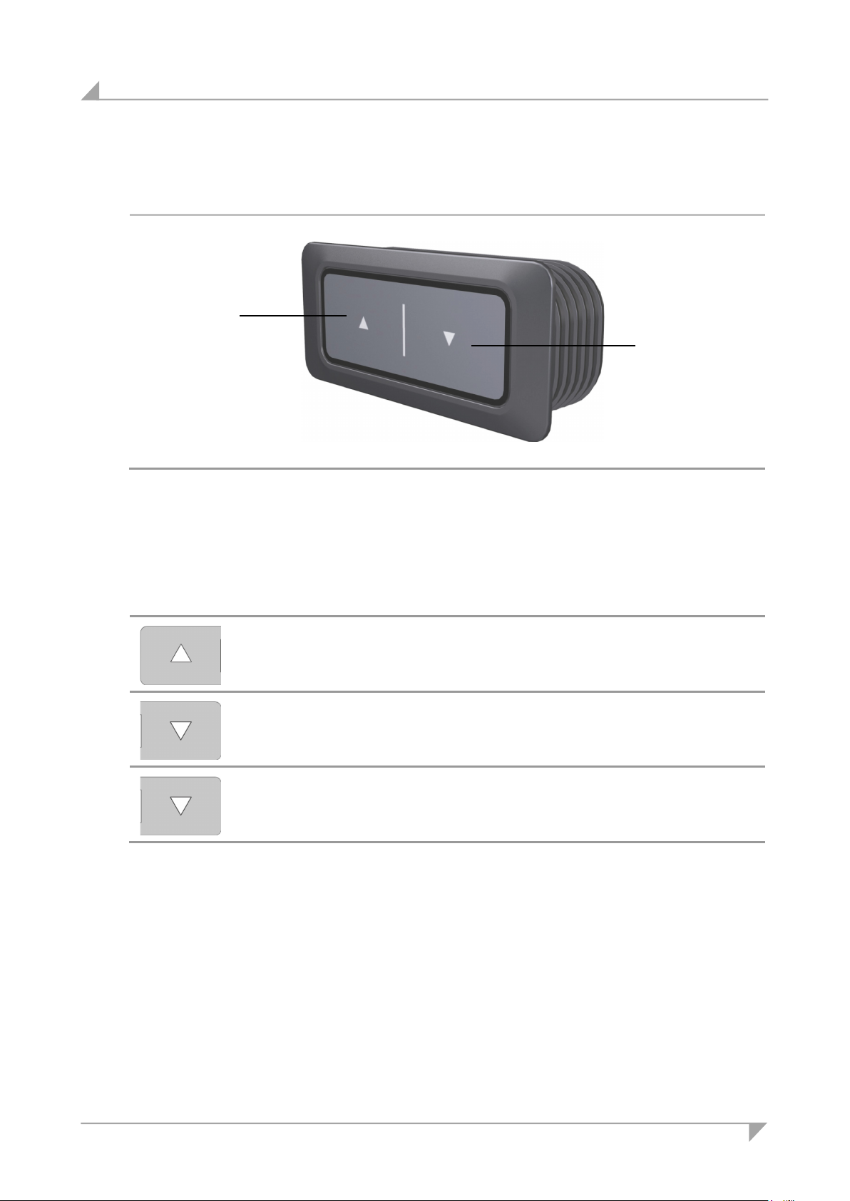
A
8.6 Functions of the TOUCHbasic-inlay keypad
Figure 52 TOUCHbasic-inlay control keypad
Key for adjusting downwards
8.6.1 Key assignments for the TOUCHbasic-inlay keypad
D Key for adjusting upwards
Press the key on the control keypad to raise or lower the table. Keep pressing the key until
the desired height of the table is reached.
Adjusting downwards
Adjusting upwards
For carrying out the reset motion after a malfunction
(refer to 6.1).
62 78438 7.0
Page 63
System ID21 Operating the control keypads
A
Button
Function
D
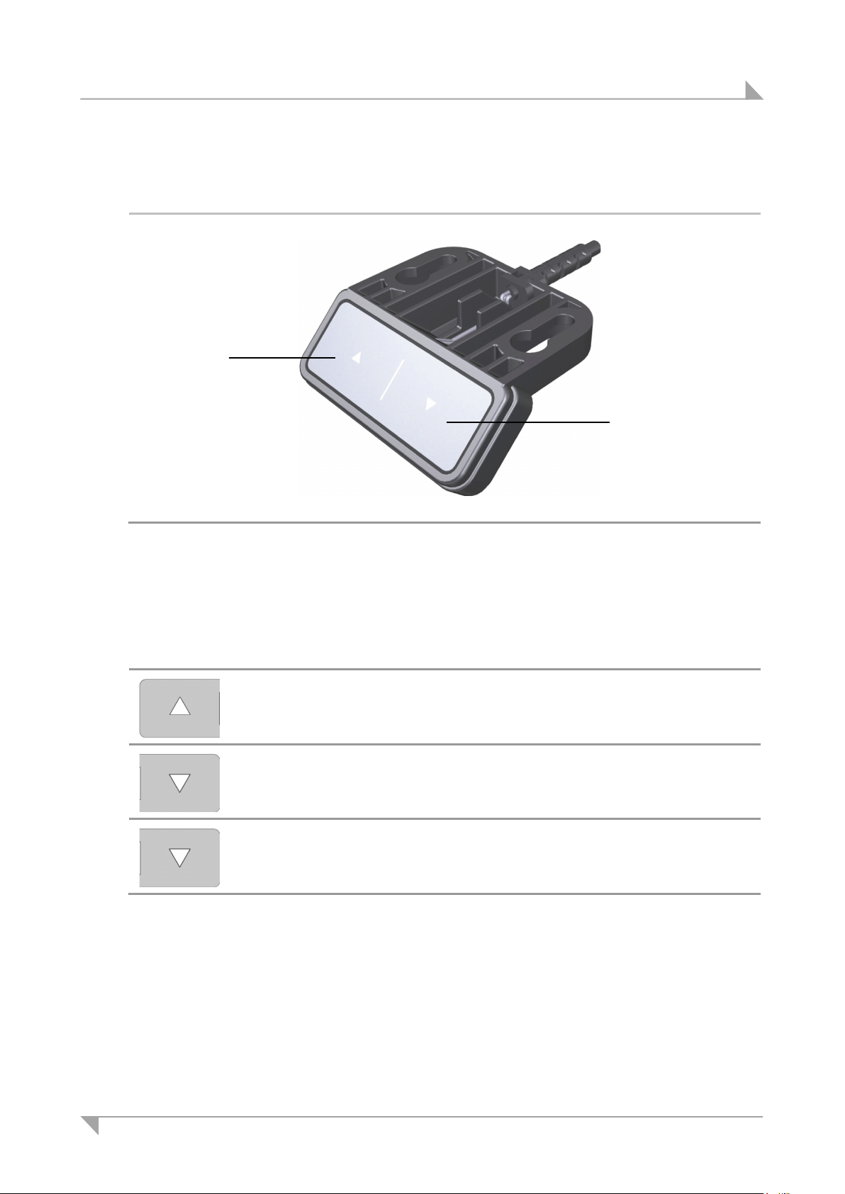
A
8.7 Functions of the TOUCHbasic-down keypad
Figure 53 TOUCHbasic-down control keypad
Key for adjusting downwards
8.7.1 Key assignments for the TOUCHbasic-down keypad
Adjusting downwards
Adjusting upwards
For carrying out the reset motion after a malfunction
(refer to 6.1).
Press the key on the control keypad to raise or lower the table. Keep pressing the key until
the desired height of the table is reached.
D Key for adjusting upwards
78438 7.0 63
Page 64
Operating the control keypads System ID21
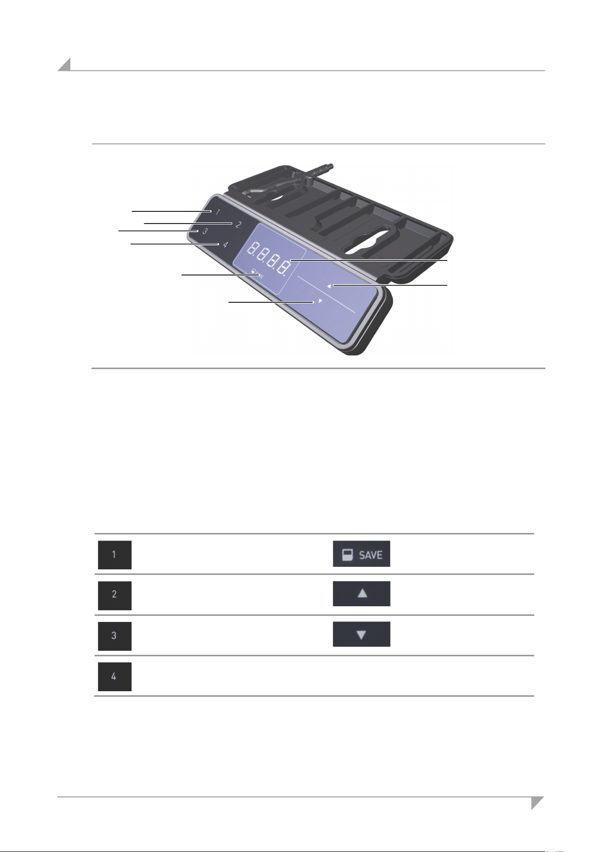
G Memory key 3
H Memory key 4
Key /
Function
Key / in-
Function
E D F H G I J
A
8.8 Functions of the TOUCHfx keypad
Figure 54 TOUCHfx control keypad
A Key for adjusting downwards D Key for adjusting upwards
E Memory key 1 F Memory key 2
I Display J Memory key
8.8.1 Key assignments for the TOUCHfx keypad
indicator
Memory key 1
Memory key 2
Memory key 3
Memory key 4
dicator
Memory key
Adjusting upwards
Adjusting downwards
64 78438 7.0
The display on the TOUCHfx control keypad is a 4-character positional and information display.
Using the keys for upwards or downwards adjustments: Press and hold the corresponding key un-
til the desired position is reached.
Page 65
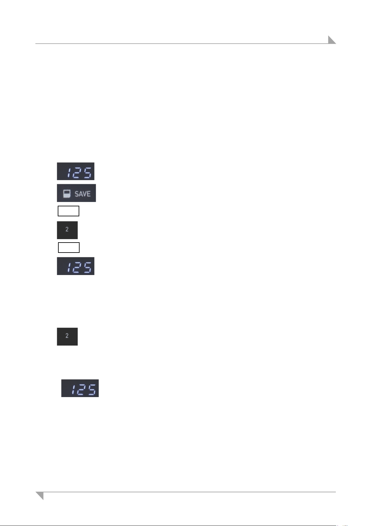
System ID21 Operating the control keypads
1
The position is shown on the display (e.g. 125 cm).
1
S – is now shown on the display.
2 Press the desired memory key (e.g. 2).
3
1
2 Release the key when the table has reached the saved position.
The current (saved) position is shown on the display.
8.8.2 Advanced functions
Saving a position
Any table position can be saved using this function.
When the control unit is turned on for the first time, all positions are equal to the smallest table
position (the lower end position).
Only one table position can be stored per memory key.
To save a position, proceed as follows:
Move the table to the position that you want to save.
Press the Save key.
5 -
5 2
Adjusting the table to a saved height position
This function allows you to set the table to a saved table position.
S 2 is shown on the display.
The set table position is now saved for the selected memory key.
A double-click noise can then be heard. After about 2 seconds, the saved
table position is displayed.
Press and hold the memory key that corresponds to the desired table
position (e.g. position 2).
The table will move as long as the memory key is pressed. If you
release this key before the saved position is reached, the table will
stop before it reaches this position.
78438 7.0 65
Page 66
Operating the control keypads System ID21
I
J
Key /
Function
Key / in-
Function
E D F H G I J
A
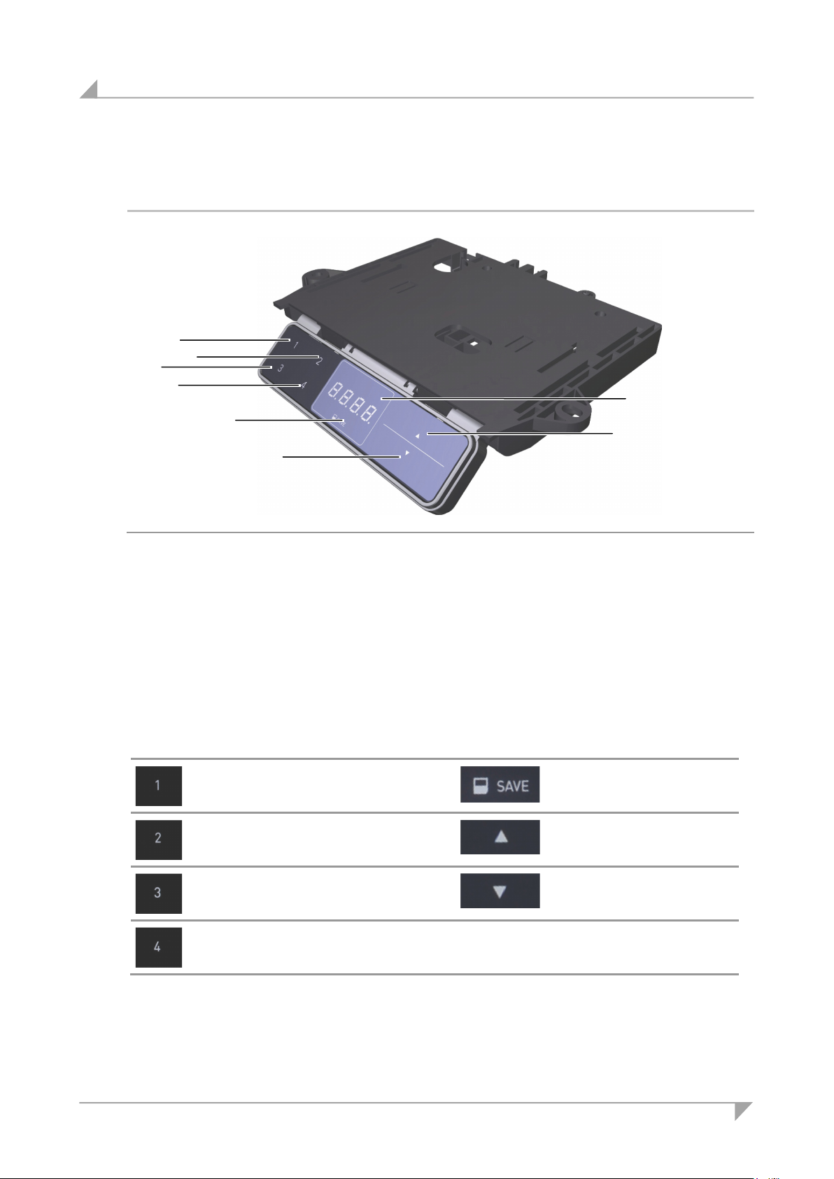
8.9 Functions of the TOUCHdown keypad
Figure 55 TOUCHdown control keypad
A Key for adjusting downwards D Key for adjusting upwards
E Memory key 1 F Memory key 2
G Memory key 3 H Memory key 4
Display
8.9.1 Key assignments for the TOUCHdown keypad
indicator
Memory key 1
Memory key 2
Memory key 3
Memory key
dicator
Memory key
Adjusting upwards
Adjusting downwards
Memory key 4
The display on the TOUCHdown control keypad is a four-character positional and information dis-
play.
Using the keys for upwards or downwards adjustments: Press and hold the corresponding key un-
til the desired position is reached.
66 78438 7.0
Page 67
System ID21 Operating the control keypads
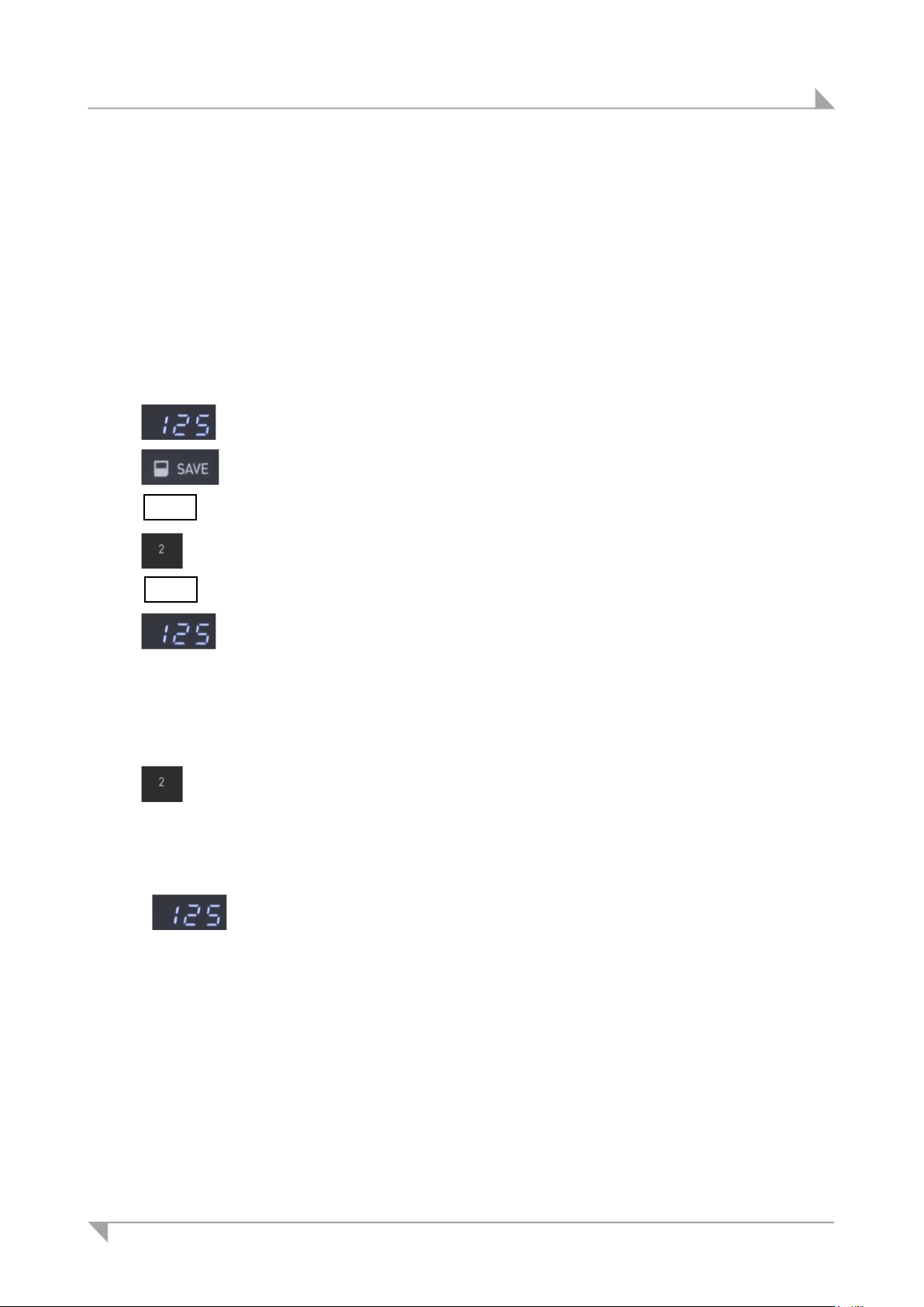
1 Move the table to the position that you want to save.
The position is shown on the display (e.g. 125 cm).
2 Press the Save key.
S – is now shown on the display.
3 Press the desired memory key (e.g. 2).
S 2 is shown on the display.
4 The set table position is now saved for the selected memory key.
1
2 Release the key when the table has reached the saved position.
The current (saved) position is shown on the display.
8.9.2 Advanced functions
Saving a position
Any table position can be saved using this function.
When the control unit is turned on for the first time, all positions are equal to the smallest table
position (the lower end position).
Only one table position can be stored per memory key.
To save a position, proceed as follows:
5 -
5 2
Adjusting the table to a saved height position
This function allows you to set the table to a saved table position.
Activating and deactivating the display lock
Swipe across the display to activate or deactivate the display lock. A key icon is shown on the
display when it the key functions are locked.
Requirement: The display must be activated (e.g. showing the current height). To activate the dis-
play, simply press a key (e.g. the UP key) briefly.
A double-click noise can then be heard. After about 2 seconds, the saved
table position is displayed.
Press and hold the memory key that corresponds to the desired table position (e.g. position 2).
The table will move as long as the memory key is pressed. If you release this key before the saved position is reached, the table will stop
before it reaches this position.
1 Swipe the display in the vicinity of the keys. Make sure that the display is swiped only slightly. Do
not press any of the keys!
2 The display lock can be activated and deactivated by swiping.
78438 7.0 67
Page 68
Operating the control keypads System ID21
Key /
Function
Key / in-
Function
E
A D F J I
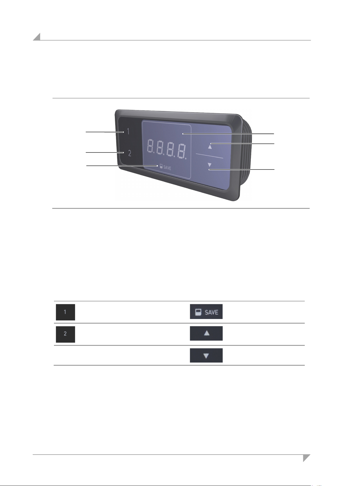
8.10 Functionality of the TOUCHinlay keypad
The TOUCHinlay control keypad has two keys for the up/down adjustment movements, two
memory keys, a save key and a display.
Figure 56 TOUCHinlay control keypad
A Key for adjusting downwards D Key for adjusting upwards
E Memory key 1 F Memory key 2
I Display J Memory key
8.10.1 Key assignments for the TOUCHinlay keypad
indicator
Memory key 1
Memory key 2
The display on the TOUCHinlay control keypad is a four-character positional and information dis-
play.
dicator
Memory key
Adjusting upwards
Adjusting downwards
Using the keys for upwards or downwards adjustments: Press and hold the corresponding key un-
til the desired position is reached.
68 78438 7.0
Page 69
System ID21 Operating the control keypads
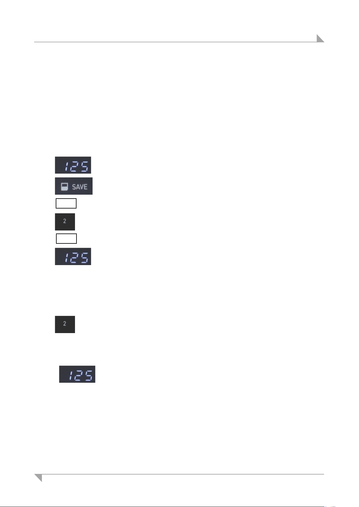
1
The position is shown on the display (e.g. 125 cm).
2
S – is now shown on the display.
3 Press the desired memory key (e.g. 2).
4
1
2 Release the key when the table has reached the saved position.
The current (saved) position is shown on the display.
8.10.2 Advanced functions
Saving a position
Any table position can be saved using this function.
When the control unit is turned on for the first time, all positions are equal to the smallest table
position (the lower end position).
Only one table position can be stored per memory key.
To save a position, proceed as follows:
Move the table to the position that you want to save.
Press the Save key.
5 -
5 2
Adjusting the table to a saved height position
This function allows you to set the table to a saved table position.
S 2 is shown on the display.
The set table position is now saved for the selected memory key.
A double-click noise can then be heard. After about 2 seconds, the saved
table position is displayed.
Press and hold the memory key that corresponds to the desired table
position (e.g. position 2).
The table will move as long as the memory key is pressed. If you
release this key before the saved position is reached, the table will
stop before it reaches this position.
78438 7.0 69
Page 70
Troubleshooting System ID21
9. Troubleshooting
This chapter describes troubleshooting methods for fixing problems. If you experience an error
that is not listed in this table, please contact your supplier or sales agent.
CAUTION
Only qualified specialists who have received electrician training should carry out troubleshooting
and repairs.
9.1 Malfunctions
Problem Possible cause Solution
The drives are not
functioning.
The drives are running
in only one direction.
The control unit or
control keypad is not
functioning properly.
There is no mains supply
voltage.
The drives are not connected. Connect the motor's connecting
A plug has a bad contact. Make sure that the motor cable, the
A control unit or a control
keypad is defective.
There was a power outage during an adjustment movement or
the power cable was disconnected during a movement.
The control unit, drive, or control
keypad is defective.
There is no mains supply
voltage.
The control keypad is not
connected.
Connect the mains power supply.
cable to the control unit.
power supply and the control keypad are properly and firmly connected.
Please contact your supplier or
sales agent.
Carry out the reset movement.
Please contact your supplier or
sales agent.
Connect the mains power supply.
Connect the control keypad.
The control unit, power cable or
control keypad is defective.
A plug has a bad contact. Make sure that the plugs are firmly
70 78438 7.0
Please contact your supplier or
sales agent.
seated and properly connected.
Page 71
System ID21 Troubleshooting
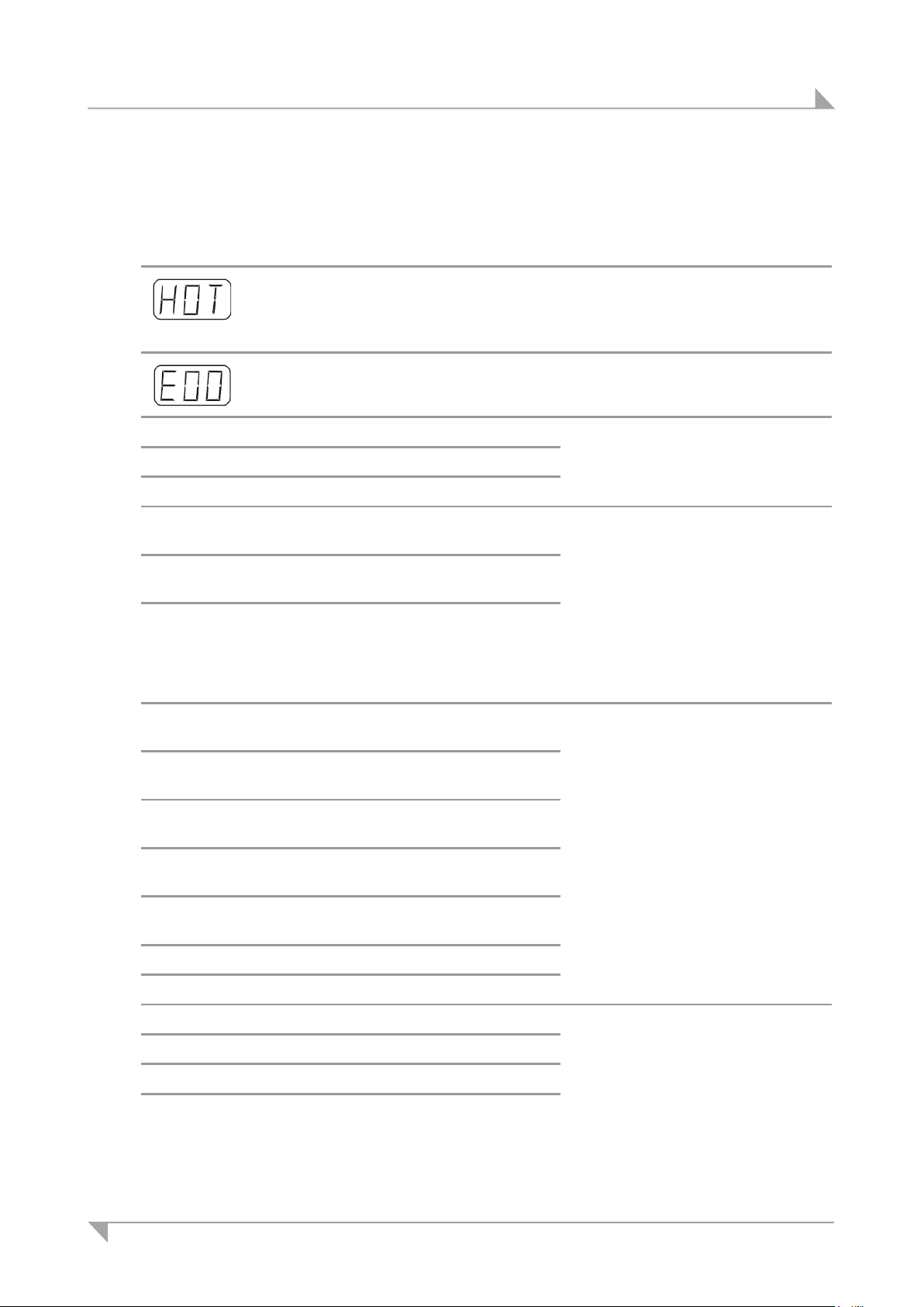
9.2 Error messages on the control keypad's display
Displayed error
message
00 Internal error channel 1 Switch off the control unit.
01 Internal error channel 2
02 Internal error channel 3
12 Malfunction channel 1
13 Malfunction channel 2
14 Defect on channel 3 (COMPACT only)
Possible cause Solution
The SMART/COMPACT control unit is
equipped with a thermal protective
mechanism which has been triggered.
There is an internal error in the
SMART/COMPACT control unit.
(SMART/COMPACT)
(SMART/COMPACT)
Wait until the control unit has cooled
down and the message HOT is no
longer displayed. The control unit is
once again ready for operations.
Proceed according to the instructions in the error list below.
Please contact your supplier or
sales agent.
Disconnect all connecting cables
from the control unit.
Find and correct the short circuit.
Reconnect the control unit and resume operations.
Connect the correct lifting column to
the correct socket.
Reconnect the control unit and resume operations.
24 Excessive current at lifting column M1
(SMART/COMPACT)
25 Excessive current at lifting column M2
(SMART/COMPACT)
26 Excessive current at lifting column M3
(COMPACT)
48 Excessive current at drive group 1
(SMART/COMPACT)
49 Excessive current at drive group 2
(COMPACT)
60 Collision protection
62 Excessive current at control unit
36 Plug detection at socket M1 Connect the correct lifting column to
37 Plug detection at socket M2
38 Plug detection at socket M3
61 Lifting columns are incorrect
Remove the jammed objects from
the range of movement.
Table is overloaded: remove the
excess load.
Please contact your supplier or
sales agent.
the correct socket.
Carry out the reset movement.
78438 7.0 71
Page 72

Troubleshooting System ID21
Displayed error
Possible cause Solution
message
55 Synchronization of drive group 1 Remove the load from the table.
56 Synchronization of drive group 2
Carry out the reset movement.
The error is still displayed after the
reset: Please contact your supplier
or sales agent.
67 The voltage is too high. Disconnect the mains cable from the
power supply.
Please contact your supplier or
sales agent.
70 Changed drive configuration First option:
Disconnect the mains power cable
from the power supply and wait at
least five seconds.
Connect the mains power cable to
the power supply.
Carry out the reset movement.
Second option:
Simultaneously press the Memory
position 1 and 2 keys and the Ta-
bletop up key. Hold the keys down
for about ten seconds
and then release them.
S 1 is now shown on the display.
Press down on the Tabletop up key
until S 7 appears in the display.
Press the Memory key.
Third option:
Please contact your supplier or
sales agent.
72 78438 7.0
Page 73

System ID21 Troubleshooting
Displayed error
message
71 Change the anti-pinch configuration Refer to error 70.
81 Internal error Carry out the reset movement.
Possible cause Solution
Disable the sensor unit:
Remove a sensor unit from the
COMPACT control unit.
The error E71 appears on the display.
Verify that the sensor unit is no
longer connected to the COMPACT
control unit.
Press down on the Tabletop up key
until the tabletop has reached its
upper position.
The COMPACT control unit clicks
three times: the sensor unit is now
deactivated.
Disconnect the mains cable from the
power supply. Reconnect the power
supply cable after a few seconds.
A manual reset may be required if there was a power outage (or if the power cord was dis-
connected) during the height adjustment process.
If this error is displayed multiple
times:
Disconnect the mains cable from the
power supply. Please contact your
supplier or sales agent.
78438 7.0 73
Page 74

Troubleshooting System ID21
There is a short circuit on the
9.3 Error messages, as indicated by clicking tones from the control unit
Number of clicks Explanation Solution
2 Normal operations (The system
is working properly.)
1 Emergency mode (The lifting
columns cannot be used in
emergency mode.)
3 – 6 The last shutdown was incom-
plete.
Forced reset movement
-
Check the LEDs and the error code
on the display of the control keypad.
Check the LEDs and the error code
on the display of the control keypad.
9.4 Error messages displayed by the LEDs (COMPACT control unit)
LED display Explanation Solution
Control unit LED is
flashing
Internal error Carry out the reset movement.
Disconnect the mains cable from the
power supply. Reconnect the power
supply cable after a few seconds.
Disconnect the mains cable from the
power supply. Please contact your
supplier or sales agent.
Control unit LED is
illuminated.
The LED over the
lifting column port is
flashing.
The LED over the
lifting column port is
illuminated.
A reset movement is required. Carry out the reset movement.
Note: This LED is also illuminated
during the reset movement or after
the reset was not executed to completion. It goes off when the reset is
finished.
lifting column.
A lifting column is missing. Connect the correct lifting column to
Disconnect the control unit's connecting cable.
Find and correct the short circuit.
Reconnect the control unit and resume operations.
the correct socket.
Carry out the reset movement.
74 78438 7.0
Page 75

System ID21 Maintenance and cleaning
10. Maintenance and cleaning
You should only use spare parts which have been manufactured or approved by DewertOkin.
Only these parts will guarantee a sufficient level of safety.
10.1 Maintenance
Periodic inspections should be carried out in accordance with the German Social Accident Insurance (DGUV) guidelines / provision 3. A qualified electrician should carry out this inspection.
The following should also be checked frequently:
Type of check Explanation Time interval
Look over the housing periodically for any signs of
damage.
Look over the cables, wires
and strain relief mechanisms.
Check the resistance of the
protective earth and check
for leakage current.
Check the function and
safety of the electrical system.
10.2 Cleaning
Clean the ID21 system components using a dry anti-static cloth as often as needed.
Check the housing for breaks or
cracks. The IP-class protection will
be impaired by any breakage or
cracks.
Check the cables for pinching or
shearing. Also check the strain
relief and kink protection mechanisms, in particular after any mechanical load.
The leakage current and the protective earth resistance should be
checked by a trained electrician.
A qualified electrician should carry
out this inspection. (Refer to the
"Electrical connection" section in
the "Installation" Chapter.)
At least every six months.
At least every six months.
At least every six months.
Periodic inspections can be
carried out at intervals
based on the risk assessment which you conduct for
your end product.
NOTICE
• Always disconnect the mains power plug from the ID21 system before you start to clean it.
• Be sure that you do not damage the connecting cables during the cleaning.
78438 7.0 75
Page 76

Technical specifications and product designation System ID21
11. Technical specifications and product designation
11.1 Table
Dimensions
Complete system DESKFRAME C ID-A 30x30
DESKFRAME C ID-A 40x40
Tabletop (permissible dimensions) for table with two lifting columns:
Length
Width
Height
Load
Complete system: DESKFRAME C ID-A 30x30 + DESKFRAME C ID-A 30x30-3L
DESKFRAME C ID-A 40x40 + DESKFRAME C ID-A 40x40-3L
Tabletop (permissible dimensions) for table with three lifting columns:
Length
Width
Height
Load
Table frame
Length x width x height
Table legs
Length x width x height
Ambient conditions for operation, storage and transport
Temperatures for transport and storage From -20 °C to +50 °C
1200 to 2000 mm
800 to 1000 mm
19 to 30 mm
Max. 120 kg
1200 to 2000 mm / 1200 to 1500 mm
800 to 1000 mm
19 to 30 mm
Max. 150 kg
Depending on your model
Depending on your model
From -4 °F to +122 °F
Operating temperature From +10 °C to +40 °C
From +50 °F to +104 °F
Relative humidity From 30% to 75%
Air pressure From 800 hPa to 1060 hPa
Height < 2000 m
76 78438 7.0
Page 77
System ID21 Technical specifications and product designation
11.2 SMART and COMPACT control units
11.2.1 SMARTeco / SMARTneo / SMARTneo-pro control unit
Control unit: SMARTeco SMARTneo SMARTneo-pro
Rated voltage /
USA: 120V AC / 60Hz / 5 A
Frequency /
Rated current consumption
Standby power at rated
EU: 230V AC / 50Hz / 2.5 A
≤ 0.3 W
voltage
Rated secondary power
216 VA 240 VA
(sum of all motor channels)
Mode of operations1 Intermittent duty 2 minutes /18 minutes
Protection class I II
Protection degree IP20
Dimensions and weight
Length x width x height
186 x 100 x 30 218 x 84.5 x 36.5
(in mm)
Weight 305 g 317 g 320 g
Ambient conditions for operation, storage and transport
Temperatures for transport
and storage
From -20 °C to +50 °C
From -4 °F to +122 °F
Operating temperature From +10 °C to +40 °C
From +50 °F to +104 °F
Relative humidity From 30% to 75%
Air pressure From 800 hPa to 1060 hPa
Height < 2000 m
1)
Mode of operation: intermittent duty 2 minutes/18 minutes. This means that after the unit is oper-
ated with its rated load for up to two minutes it must then be paused for 18 minutes. The system
can malfunction if this pause is not observed!
78438 7.0 77
Page 78

Technical specifications and product designation System ID21
11.2.2 COMPACTeco / COMPACTeco+ control unit
Control unit: COMPACTeco COMPACTeco+
Rated voltage /
USA: 120V AC / 60 Hz / 10 A
Frequency /
Rated current consumption
Standby power at rated
≤ 0.3 W ≤ 0.1 W
EU: 230V AC / 50Hz / 5 A
voltage
Rated secondary power
360 VA
(sum of all motor channels)
Mode of operations1 Intermittent duty 2 minutes /18 minutes
Protection class I
Protection degree IP20
Dimensions and weight
Length x width x height
264 x 103 x 37
(in mm)
Weight 523 g
Ambient conditions for operation, storage and transport
Temperatures for transport
and storage
From -20 °C to +50 °C
From -4 °F to +122 °F
Operating temperature From +10 °C to +40 °C
From +50 °F to +104 °F
Relative humidity From 30% to 75%
Air pressure From 800 hPa to 1060 hPa
Height < 2000 m
1)
Mode of operation: intermittent duty 2 minutes/18 minutes. This means that after the unit is oper-
ated with its rated load for up to two minutes it must then be paused for 18 minutes. The system
can malfunction if this pause is not observed!
78 78438 7.0
Page 79
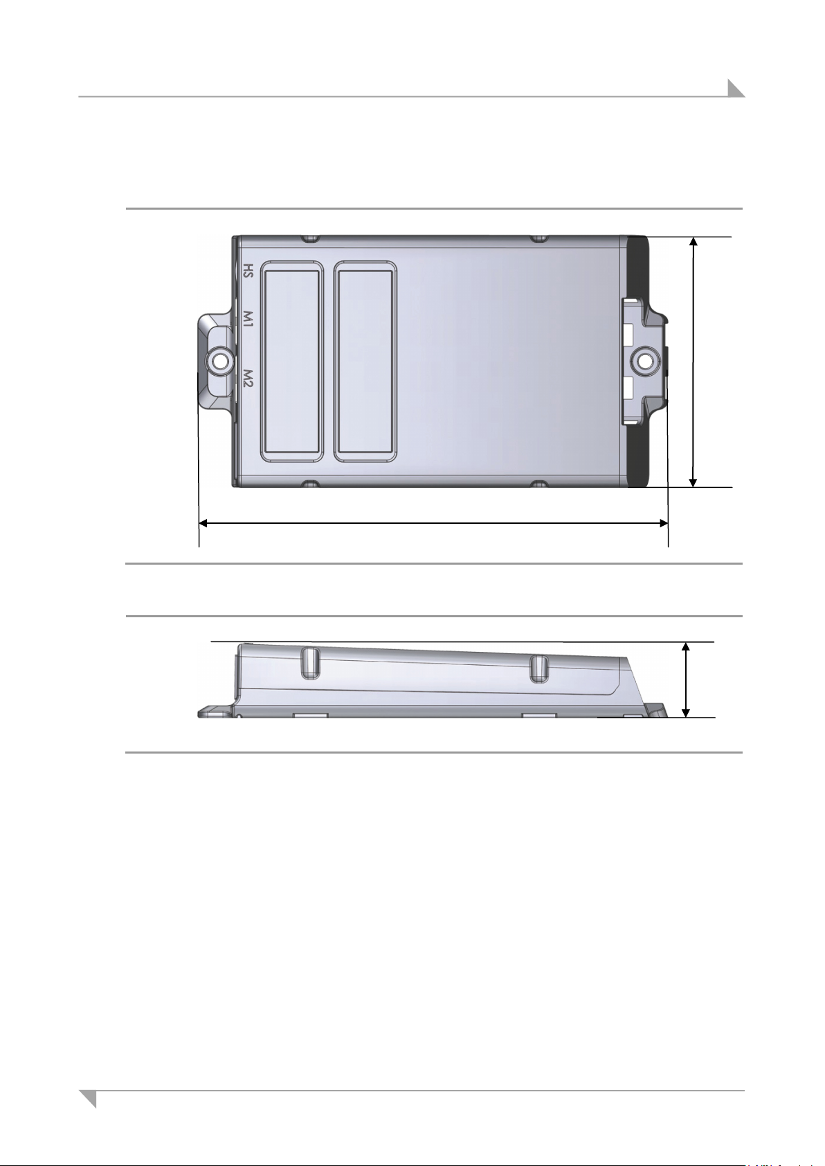
System ID21 Technical specifications and product designation
186
100
30
11.3 Dimensions of the SMARTeco control unit
Figure 57 SMARTeco control unit, top view (in mm)
Figure 58 SMARTeco control unit, side view (in mm)
78438 7.0 79
Page 80

Technical specifications and product designation System ID21
200
84.5
36.5
218
11.4 Dimensions of the SMARTneo / SMARTneo-pro control unit
Figure 59 SMARTneo / SMARTneo-pro control unit, top view (in mm)
Figure 60 SMARTneo / SMARTneo-pro control unit, side view (in mm)
80 78438 7.0
Page 81
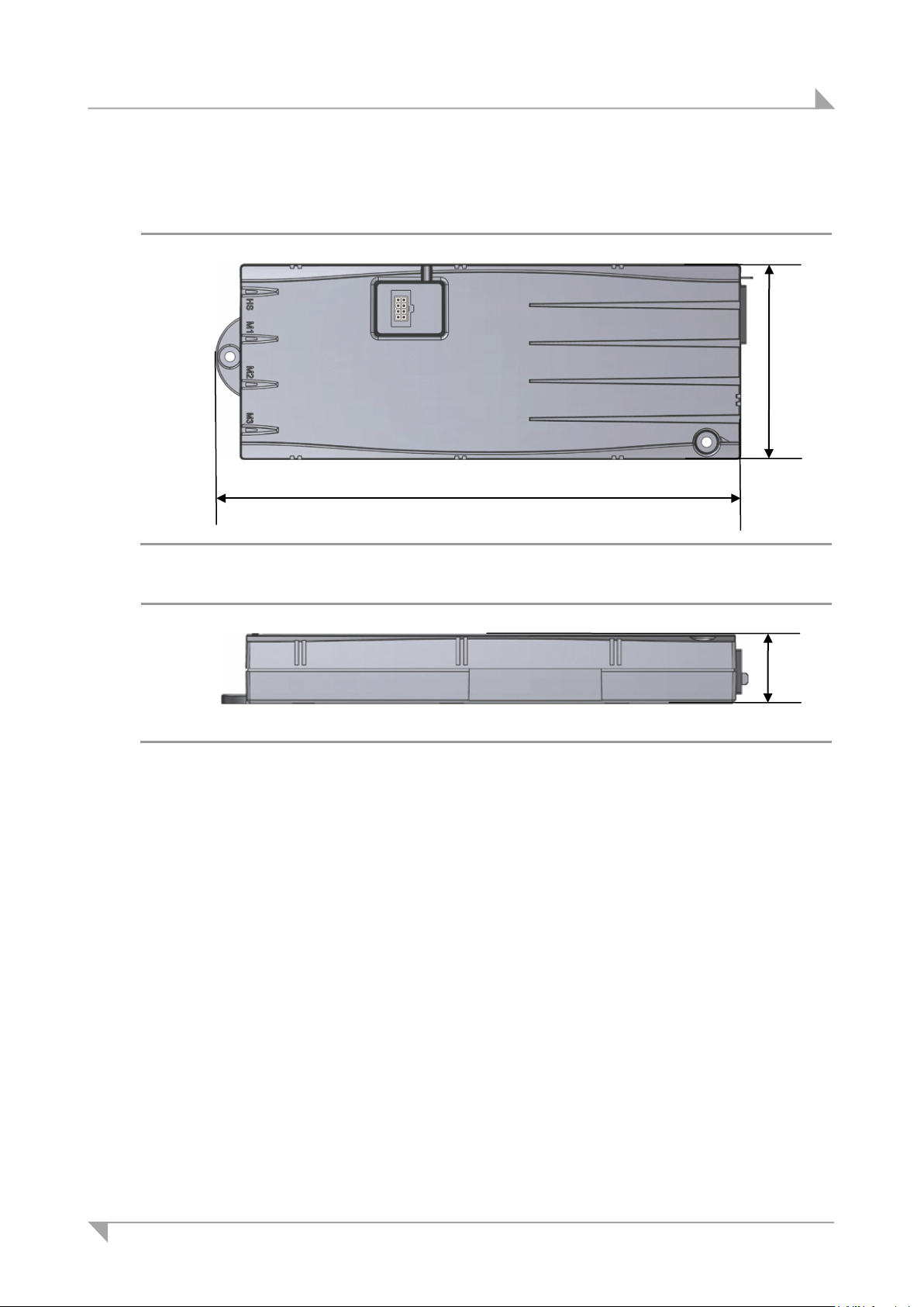
System ID21 Technical specifications and product designation
264
103
37
11.5 Size of COMPACT control unit
Figure 61 SMART control unit, top view (in mm)
Figure 62 COMPACT control unit, side view (in mm)
78438 7.0 81
Page 82

Technical specifications and product designation System ID21
11.6 ID21 lifting column
Input voltage 24 V DC – 29 V DC
Current consumption at rated load Max. 7.0 A DC
Permitted push force Max. 800 N
Bending torque, dynamic <150 Nm (in the y direction, see Figure 64)
Static torque < 200 Nm
Self-locking 800 N
Mode of operation1 at max. rated load Intermittent duty 2 minutes/18 minutes
Protection class III
Noise level ≤ 48 dB(A)
Drive type lifting column
Protection degree IP20
Colours RAL 9005, RAL 9006, RAL 9016
Stroke 650 mm
Length2 x width x height 520 mm x 80 mm x 62 mm
Length3 x width x height 1170 mm x 80 mm x 62 mm
Size of columns Exterior: 80 mm x 62 mm
Middle: 73 mm x 58 mm
Interior: 66 mm x 48 mm
Weight Approx. 7.8 kg
Cable length 1200 mm
Ambient conditions for operation, storage and transport
Transport / storage temperature From -20 °C to +50 °C
From -4 °F to +122 °F
Operating temperature From +10 °C to +40 °C
From +50 °F to +104 °F
Relative humidity From 30% to 75%
Air pressure From 800 hPa to 1060 hPa
Height < 2000 m
1)
Mode of operation: intermittent duty 2 minutes/18 minutes. This means that after the unit is oper-
ated with its rated load for up to two minutes it must then be paused for 18 minutes. The system
can malfunction if this pause is not observed!
2)
Length when retracted.
3)
Length when fully extended.
82 78438 7.0
Page 83
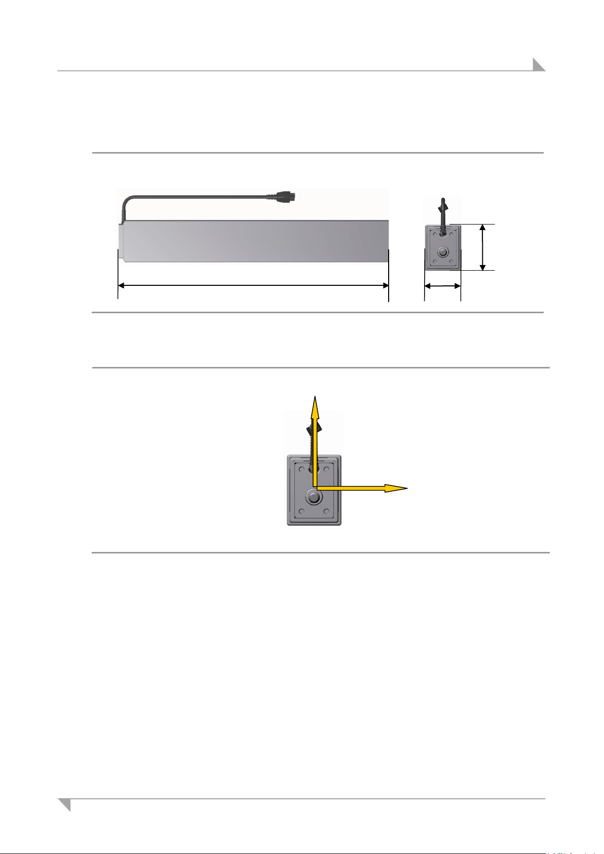
System ID21 Technical specifications and product designation
80
62
520
y
11.7 Size of the ID21 lifting column
Figure 63 ID21 lifting column (in mm)
Figure 64 Top view (head end)
78438 7.0 83
Page 84
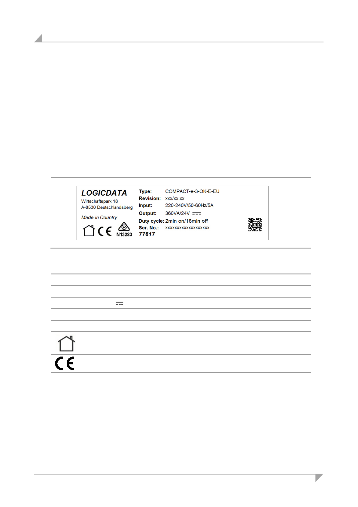
Technical specifications and product designation System ID21
11.8 Product labelling
The ratings plate shown is an example; the values shown in this example may differ from
the specifications for your configuration.
11.8.1 Ratings plate on the control unit
A ratings plate (or type label) on each control unit specifies the exact name and serial number
of the device. It also states the technical specifications valid for that particular control unit. The
following illustration shows where the specifications are located on the ratings plate of the control unit.
Ratings plate on the COMPACT control unit
Figure 65 Ratings plate example
COMPACT-e-3-OK-E-EU Model name
Revision: xxx/xx.xx Software version
Input: 220-240V/50-60Hz/5A Input voltage, frequency and current consumption
Output: 360 VA / 24 V Power and output voltage
Duty cycle: 2 min on / 18 min off Intermittent operations: 2 minutes / 18 minutes
Ser. No. Serial number
77617
Use in dry rooms only!
Conformity mark
Article number
84 78438 7.0
Page 85
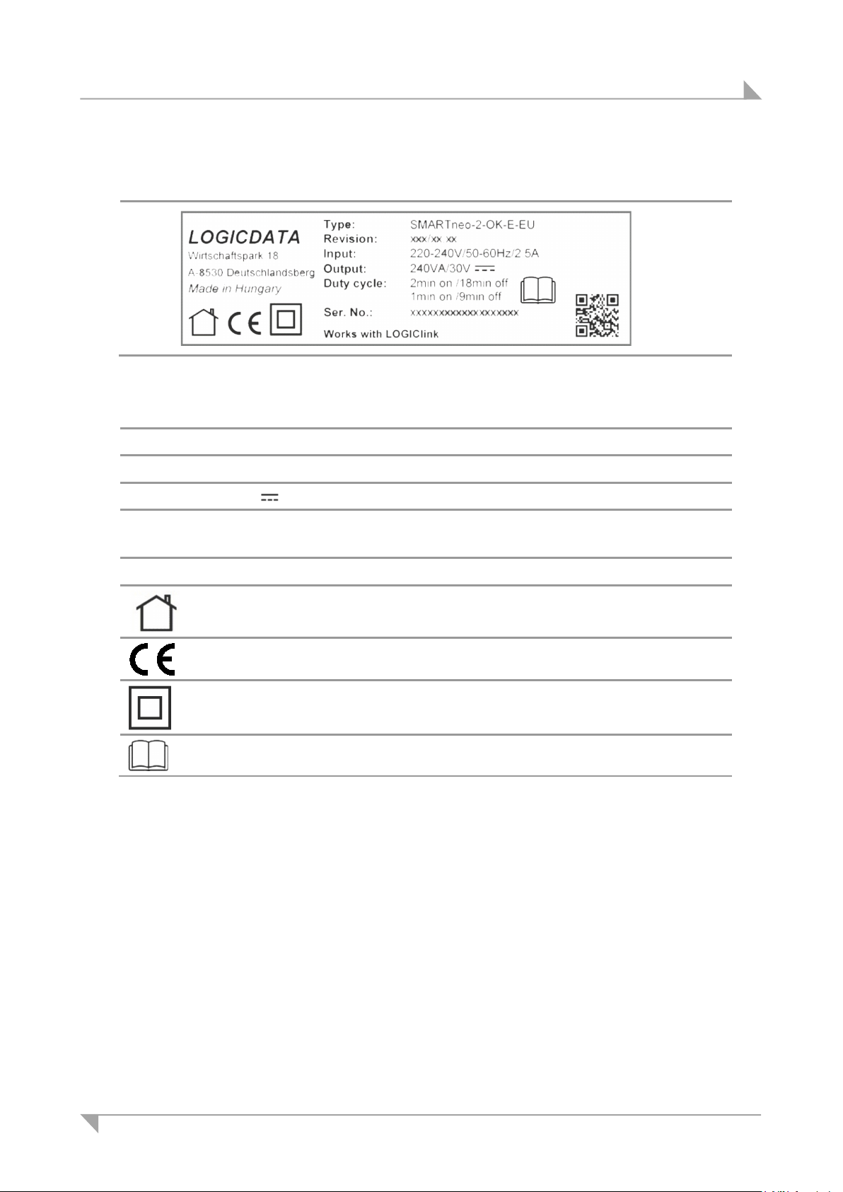
System ID21 Technical specifications and product designation
Ratings plate for the SMARTneo control unit
Figure 66 Ratings plate example
SMARTneo-2-OK-E-EU Model name
Revision: xxx/xx.xx Software version
Input: 220-240V/50-60Hz/2.5A Input voltage, frequency and current consumption
Output: 240VA/30 V Power and output voltage
Duty cycle: 2 minutes on / 18 minutes off
1 minute on / 9 minutes off
Intermittent operations: 2 minutes / 18 minutes
1 minute / 9 minutes
Ser. No. Serial number
Use in dry rooms only!
Conformity mark
Protection class: II
Read the manual!
78438 7.0 85
Page 86
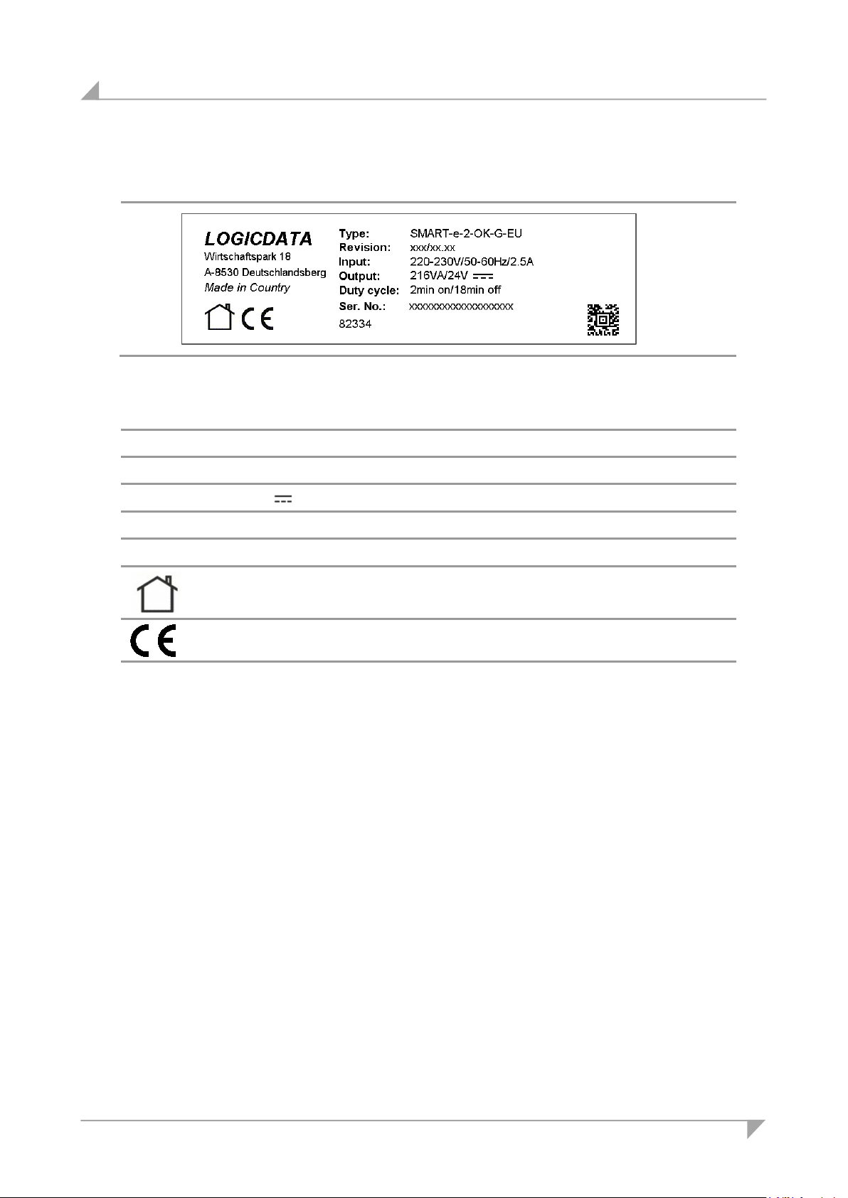
Technical specifications and product designation System ID21
Ratings plate for the SMARTeco control unit
Figure 67 Ratings plate example
SMARTeco-e-2-OK-G-EU Model name
Revision: xxx/xx.xx Software version
Input: 220-230V/50-60Hz/2.5A Input voltage, frequency and current consumption
Output: 216 VA / 24 V Power and output voltage
Duty cycle: 2 min on / 18 min off Intermittent operations: 2 minutes / 18 minutes
Ser. No. Serial number
Use in dry rooms only!
Conformity mark
82334
Article number
86 78438 7.0
Page 87
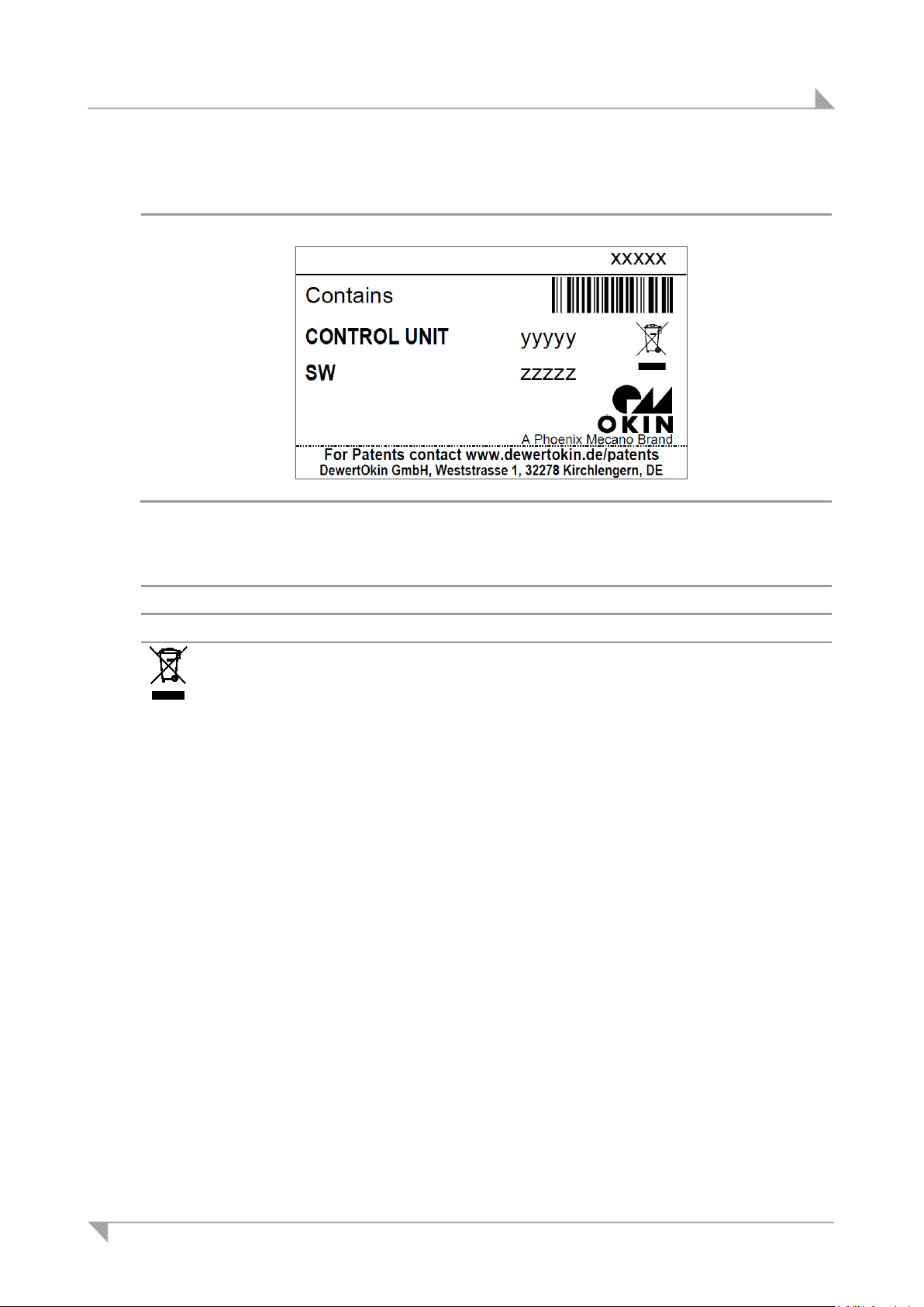
System ID21 Technical specifications and product designation
SMARTeco, SMARTneo, SMARTneo-pro and COMPACT control unit stickers
Figure 68 Sticker (an example)
Xxxxx Article number
CONTROL UNIT yyyyy Type designation and ID of control unit
SW zzzzz ID of software
Follow all special disposal instructions!
78438 7.0 87
Page 88
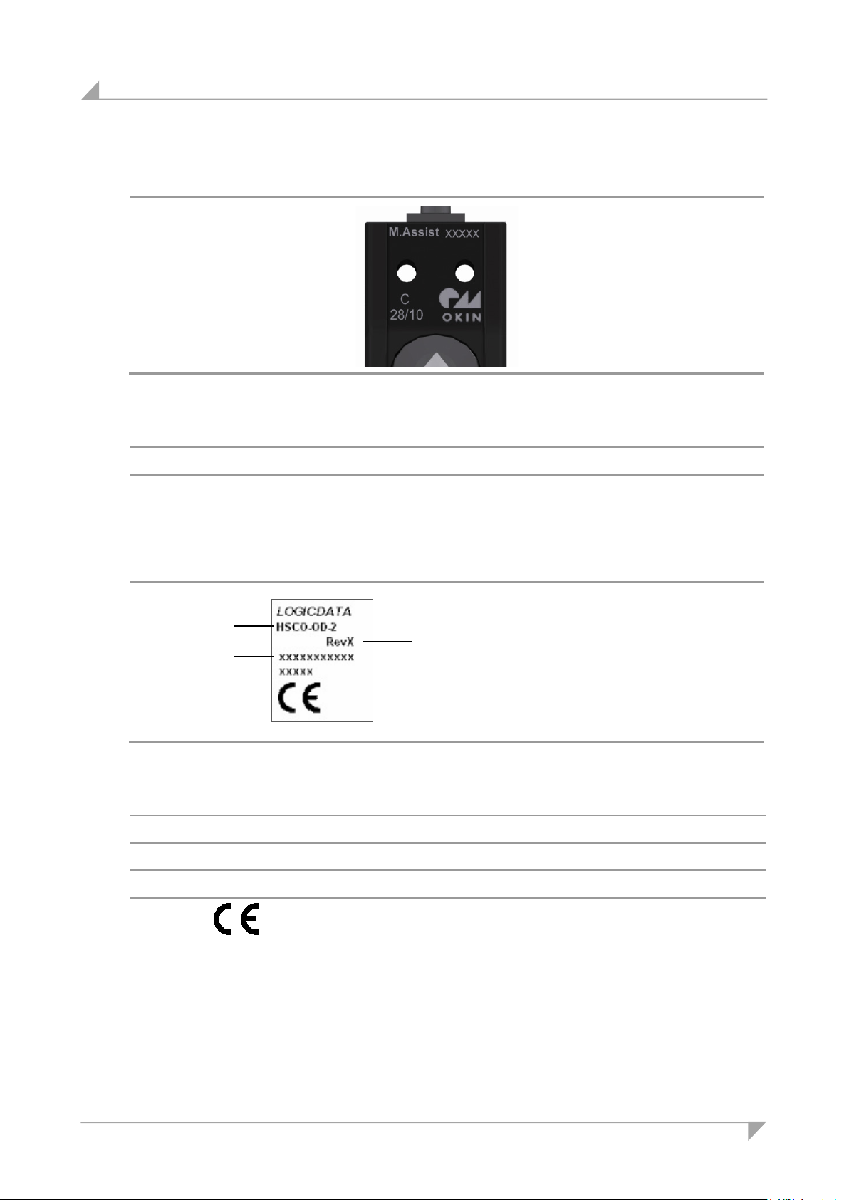
Technical specifications and product designation System ID21
C
11.8.2 Ratings plate on the Motion Assist control keypad
Figure 69 Ratings plate example
M. Assist Type designation for the Motion Assist
Xxxxxxx Article number
Prod.date 28/10 Calendar week / year
11.8.3 Ratings plates for the control keypads
A
Figure 70 Ratings plate example
Position Designation (example) Explanation
A HSF_MDF_4M4_LD Type designation (abbreviation)
B RevX Revision
C xxxxxxxxxxx Serial number
B
Conformity mark
88 78438 7.0
Page 89
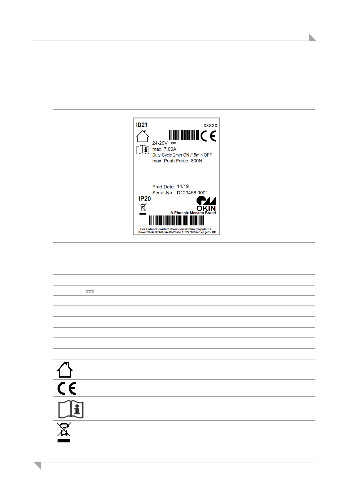
System ID21 Technical specifications and product designation
11.8.4 Ratings plate on the ID21 lifting column
A ratings plate (type label) on each lifting column specifies the exact name and serial number
of the lifting column. It also states the technical specifications valid for that particular lifting column. The following illustration shows where the specifications are located on the ratings plate.
Figure 71 Ratings plate example
ID21 Model name
Xxxxx Article number
24V – 29V Input voltage
Max. 7.0A Current consumption
Duty cycle: 2 minutes ON / 18 minutes OFF Intermittent operations: 2 minutes / 18 minutes
max. Push Force Push force
Prod.date Production date: Calendar week / year
Serial No. Serial number
IP20 Protection degree
Use in dry rooms only!
Conformity mark
Follow the special assembly instructions!
Follow all special disposal instructions!
78438 7.0 89
Page 90
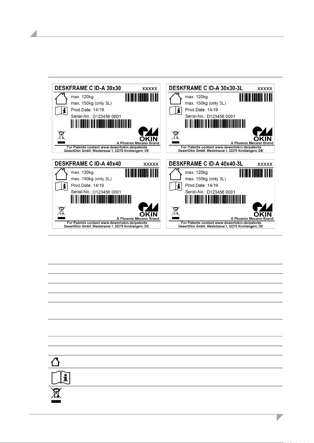
Technical specifications and product designation System ID21
11.8.5 Ratings plate on the table frame
Figure 72 Rating plates (examples)
DESKFRAME C ID-A 30x30 Model name
DESKFRAME C ID-A 30x30-3L Model name
DESKFRAME C ID-A 40x40 Model name
DESKFRAME C ID-A 40x40-3L Model name
Xxxxx Article number
Max. 120kg Maximum load: DESKFRAME C ID-A 30x30
DESKFRAME C ID-A 40x40
max. 150kg (only 3L) Maximum load: DESKFRAME C ID-A 30x30-3L
DESKFRAME C ID-A 40x40-3L
Prod.date Production date: Calendar week / year
Serial No. Serial number
Use in dry rooms only!
Follow the special assembly instructions!
Follow all special disposal instructions!
90 78438 7.0
Page 91
System ID21 Disposal
12. Disposal
12.1 Packaging material
The packaging material should be sorted into recyclable components and then disposed of in
accordance with the appropriate national environmental regulations (in Germany according to
the recycling law KrWG from 01.06.2012; internationally according to the EU Directive
2008/98/EC (Waste Framework Directive WFD as of 12.12.2008)).
12.2 Drive components
The ID21 system consists of electronic components, cables and metal and plastic parts. You
should observe all corresponding national and regional environmental regulations when disposing of the system.
The disposal of the product is regulated in Germany by Elektro-G, internationally by the EU Directive 2012/19/EC (WEEE), or by any applicable national laws and regulations.
The ID21 system components should not be disposed of with normal household waste!
78438 7.0 91
Page 92

Declaration of Incorporation/Installation
According to Appendix II of the EU Machinery Directive 2006/42/EC
The manufacturer:
DewertOkin GmbH
Weststraße 1
32278 Kirchlengern
Germany
declares that the incomplete machines described below
ID21 System
complies with the following basic requirements of the Machinery Directive (2006/42/EC):
Sections: 1.1.3; 1.3.3; 1.3.4; 1.3.7; 1.5.1; 1.5.2; 1.5.5; 1.5.6; 1.5.7; 1.5.8;
1.5.9; 1.5.10; 1.5.13
According to
DIN EN 527-1:2011
DIN EN 527-2:2017
DIN EN 527-3:2003
You may only operate this incomplete machine after you have confirmed that the end product (into
which this machine will be installed) complies with the Machinery Directive 2006/42/EC.
On request, the manufacturer is obliged to send the special documentation accompanying the
partially completed machinery in electronic form to the appropriate national institution. The special
technical documents corresponding to the machine have been created according to Appendix VII,
part B.
The following person is responsible for the technical documentation: Silvio Wauro,
Address cited above
Phone.: +49 5223 979-0
Kirchlengern, Germany. July 13, 2019 Dr.-Ing. Josef G. Groß
Managing Director
Page 93

EU Declaration of Conformity
In compliance with Appendix IV of the EMC Directive 2014/30/EU
In compliance with Appendix IV of the LVD Directive 2014/35/EU
In compliance with Appendix VI of the EU RoHS Directive 2011/65/EU
(incl. Commission delegated Directive (EU) 2015/863)
The manufacturer:
DewertOkin GmbH
Weststraße 1
32278 Kirchlengern
Germany
declares that the following products
ID11 System with DewertOkin Drive System1)
meets the requirements of the following EU directives:
Electromagnetic Compatibility Directive 2014/30/EU
Low Voltage Directive 2014/35/EU
COMMISSION DELEGATED DIRECTIVE (EU) 2015/863 of 31 March 2015 amending Annex II
to Directive 2011/65/EU of the European Parliament and of the Council as regards the list of
restricted substances.
Applied standards:
EN 60335-1:2012/A11:2014
EN 55014-1:2006/A1:2009/A2:2011
EN 55014-2:1997/A1:2001/A2:2008
EN 61000-3-2:2014
EN 61000-3-3:2013
EN 62233:2008
This declaration of conformity is no longer valid if constructional changes are made which
significantly change this drive (i.e., which influence the technical specifications found in the
instructions or the intended use)!
Kirchlengern, Germany. July 13, 2019 Dr.-Ing. Josef G. Groß
Managing Director
1)
DESKFRAME C ID-A 30x30, DESKFRAME C ID-A 30x30-3L, DESKFRAME C ID-A 40x40, DESKFRAME C ID-A 40x40-3L
with Control Unit: SMARTeco, COMPACTeco, oder COMPACTeco+, SMARTneo oder SMARTneo-pro
with Operating Elements: HSCO (1.32.000.087.30), HSU (1.32.000.32.30 oder 1.32.000.63.20), HSF (1.32.000.096.30),
with Lifting Column: ID21
Motion Assist, TOUCHfx, TOUCHbasic-inlay, TOUCHbasic-down, TOUCHdown oder
TOUCHinlay
Page 94

Page 95

Page 96

DewertOkin GmbH
Weststrasse 1
Kirchlengern 32278, Germany
Tel: +49 (0)5223/979-0
Fax.: +49 (0)5223/75182
http://www.dewertokin.de
[email protected] ID No.: 78438
 Loading...