

Page 1

Before returning this product call
1-800-4-DEWAL T
Questions? Visit us at www.dewalt.com
Des questions ? Rendez nous visite à www.dewalt.com
¿Tiene preguntas? Visítenos en www.dewalt.com
IF YOU SHOULD EXPERIENCE A PROBLEM WITH YOUR DEWALT PURCHASE,
CALL 1-800-4-DEWALT
IN MOST CASES, A DEWALT REPRESENTATIVE CAN RESOLVE
YOUR PROBLEM OVER THE PHONE.
IF YOU HAVE A SUGGESTION OR COMMENT, GIVE US A CALL.
YOUR FEEDBACK IS VITAL TO THE SUCCESS OF D
IMPROVEMENT PROGRAM.
E
WALT’S QUALITY
INSTRUCTION MANUAL
GUIDE D’UTILISATION
MANUAL DE INSTRUCCIONES
DWE7490, DWE7491
Heavy-Duty 10" (254 mm) Job Site Table Saw
INSTRUCTIVO DE OPERACIÓN, CENTROS DE SERVICIO Y PÓLIZA DE
GARANTÍA. ADVERTENCIA: LÉASE ESTE INSTRUCTIVO ANTES DE
USAR EL PRODUCTO.
Scie de table industrielle de chantier de 254mm (10po)
Sierra de banco para el lugar de trabajo de 254 mm (10 pulg.) de alta resistencia
Page 2

Page 3
Defi nitions: Safety Guidelines
The definitions below describe the level of severity for each signal word. Please read the
manual and pay attention to these symbols.
DANGER: Indicates an imminently hazardous situation which, if not avoided, will
result in death or serious injury.
WARNING: Indicates a potentially hazardous situation which, if not avoided, could
result in death or serious injury.
CAUTION: Indicates a potentially hazardous situation which, if not avoided, may
result in minor or moderate injury.
NOTICE: Indicates a practice not related to personal injury which, if not avoided,
may result in property damage.
IF YOU HAVE ANY QUESTIONS OR COMMENTS ABOUT THIS OR ANY DEWALT TOOL,
CALL US TOLL FREE AT: 1-800-4-D
WARNING: To reduce the risk of injury, read the instruction manual.
EWALT (1-800-433-9258).
General Safety Rules
WARNING: Read all instructions before operating product. Failure to follow all
instructions listed below may result in electric shock, fire and/or serious injury.
SAVE THESE INSTRUCTIONS
WARNING: FOLLOW ALL WIRING CODES and recommended electrical connections to
prevent shock or electrocution.
Double Insulation
If saw is of double-insulated construction, read the following instructions.
This symbol
constructed throughout with two separate layers of electrical insulation or one double
thickness of insulation between you and the tool’s electrical system. Tools built with this
insulation system are not intended to be grounded. As a result, your tool is equipped with a
two prong plug which permits you to use extension cords without concern for maintaining a
ground connection. Repair or replace damaged or worn cord immediately.
NOTE: Double insulation does not take the place of normal safety precautions when
operating this tool. The insulation system is for added protection against injury resulting from
a possible electrical insulation failure within the tool.
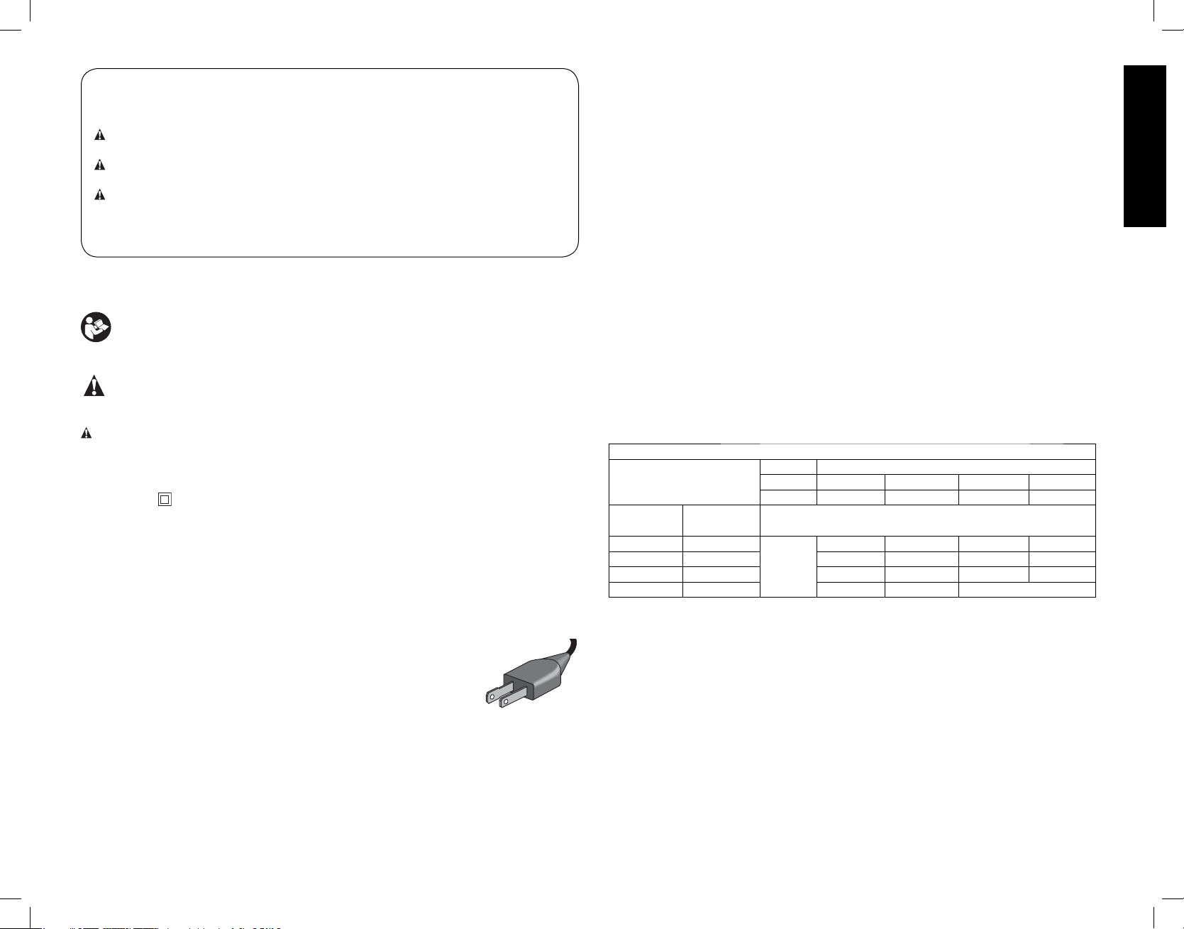
POLARIZED PLUGS
To reduce the risk of electric shock, this equipment has a polarized plug
(one blade is wider than the other). This plug will fit in a polarized outlet
only one way. If the plug does not fit fully into the outlet, reverse the plug.
If it still does not fit, contact a qualified electrician to install the proper
outlet. Do not change the plug in any way.
represents double insulated construction. Double insulated tools are
Important Safety Instructions
• TO REDUCE THE RISK OF KICKBACK AND OTHER INJURIES, use all components
of the guarding system (blade guard assembly, riving knife and anti-kickback) for every
operation for which they can be used including all thru-cutting.
• REMOVE ADJUSTING KEYS AND WRENCHES. Form habit of checking to see that
keys and adjusting wrenches are removed from spindle before turning tool on. Tools, scrap
pieces, and other debris can be thrown at high speed, causing injury.
• KEEP WORK AREA CLEAN. Cluttered areas and benches invite accidents.
• DO NOT USE THE MACHINE IN A DANGEROUS ENVIRONMENT. The use of power
tools in damp or wet locations or in rain can cause shock or electrocution. Keep your work
area well-lit to avoid tripping or placing arms, hands, and fingers in danger.
• KEEP CHILDREN AWAY. All visitors should be kept at a safe distance from work area.
Your shop is a potentially dangerous environment.
• MAKE WORKSHOP CHILDPROOF with padlocks, master switches, or by removing
starter keys. The unauthorized start-up of a machine by a child or visitor may result in
injury.
• DO NOT FORCE TOOL. It will do the job better and be safer at the rate for which it was
designed.
• USE THE RIGHT TOOL. Don’t force tool or attachment to do a job for which it was not
designed. Using the incorrect tool or attachment may result in personal injury.
• DO NOT OVERREACH. Keep proper footing and balance at all times. Loss of balance
may cause personal injury. Do not attempt to retrieve materials near the blade on the saw
table while the blade is spinning.
• MAINTAIN TOOLS WITH CARE. Keep blades sharp and clean for best and safest
performance. Follow instructions for lubricating and changing accessories. Poorly
maintained blades and machines can further damage the blade or machine and/or
cause injury.
• USE PROPER EXTENSION CORD. Make sure your extension cord is in good
condition. When using an extension cord, be sure to use one heavy enough to carry
the current your product will draw. An undersized cord will cause a drop in line voltage
resulting in loss of power and overheating.The following table shows the correct size to
use depending on cord length and nameplate ampere rating. If in doubt, use the next
heavier gauge. The smaller the gauge number, the heavier the cord.
Minimum Gauge for Cord Sets
Volts Total Length of Cord in Feet (meters)
Ampere Rating
More
Than
0 6 18 16 16 14
610 18161412
10 12 16 16 14 12
12 16 14 12 Not Recommended
• WEAR PROPER APPAREL. Do not wear loose clothing, gloves, neckties, rings,
bracelets, or other jewelry which may get caught in moving parts. Nonslip footwear is
recommended. Wear protective hair covering to contain long hair.
• ALWAYS USE SAFETY GLASSES. Also use face or dust mask if cutting operation
is dusty. Everyday eyeglasses only have impact resistant lenses, they are NOT safety
glasses.
• SECURE WORK. Use clamps to hold work when practical (such as when using a zero
clearance insert/throat plate). It's safer than using your hand and it frees both hands to
operate tool.
• TURN THE MACHINE “OFF”, AND DISCONNECT THE MACHINE FROM THE
POWER SOURCE before installing or removing accessories, before adjusting or
changing set-ups, when making repairs or changing locations. Do not touch the plug’s
metal prongs when unplugging or plugging in the cord. An accidental start-up can cause
injury.
Not More
Than
120 V 25 (7.6) 50 (15.2) 100 (30.5) 150 (45.7)
240 V 50 (15.2) 100 (30.5) 200 (61.0) 300 (91.4)
AWG
English
1
Page 4

• REDUCE THE RISK OF UNINTENTIONAL STARTING. Make sure that the switch is in
the “OFF” position before plugging in the power cord. In the event of a power failure, move
the switch to the “OFF” position. An accidental start-up can cause injury.
• Do not plug into or unplug from power source with wet hands.
• USE RECOMMENDED ACCESSORIES. Use only accessories that are recommended
by the manufacturer for your model. Accessories that may be suitable for one tool may be
hazardous when used on another tool. Consult the instruction manual for recommended
English
accessories. The use of improper accessories may cause risk of injury to persons.
• Magnetic accessories will not work on this saw.
• NEVER STAND OR SIT ON TOOL. Serious injury could occur if the tool is tipped or if the
cutting tool is unintentionally contacted.
• CHECK FOR DAMAGED PARTS. Before further use of the tool, a guard or other part
that is damaged should be carefully checked to determine that it will operate properly and
perform its intended function—check for alignment of moving parts, binding of moving
parts, breakage of parts, mounting and any other conditions that may affect its operation.
A guard or other part that is damaged should be properly repaired or replaced. Do not use
tool if switch does not turn it on and off. Damaged parts can cause further damage to the
machine and/or personal injury.
• DIRECTION OF FEED. Feed work into a blade or cutter against the direction of rotation
of the blade or cutter only. No cove cutting or freehand cuts.
• Check for adequate outfeed distance behind the saw to be sure materials can pass
unobstructed through the cut. Work support tables should be placed in proper locations
to fully support the material.
• NEVER LEAVE TOOL RUNNING UNATTENDED. TURN POWER OFF. Don’t leave
tool until it comes to a complete stop. Serious injury can result.
• DO NOT OPERATE ELECTRIC TOOLS NEAR FLAMMABLE LIQUIDS OR IN
GASEOUS OR EXPLOSIVE ATMOSPHERES. Motors and switches in these tools may
spark and ignite fumes.
• STAY ALERT, WATCH WHAT YOU ARE DOING, AND USE COMMON SENSE. DO
NOT USE THE MACHINE WHEN YOU ARE TIRED OR UNDER THE INFLUENCE
OF DRUGS, ALCOHOL, OR MEDICATION. A moment of inattention while operating
power tools may result in serious injury.
• DO NOT ALLOW FAMILIARITY (gained from frequent use of this saw) TO
REPLACE SAFETY RULES. Always remember that a careless fraction of a second is
sufficient to inflict severe injury. Use extra caution and stay alert when making repetitive
cuts. Turn off saw frequently to clean up saw dust and check adjustments to reduce
monotony.
Additional Safety Rules for Table Saws
• AVOID AWKWARD POSITIONS, where a sudden slip could cause a hand to move into
a saw blade.
• Do not attempt to retrieve materials near the blade on the saw table while the blade is
spinning.
• NEVER REACH IN BACK OF, OR AROUND, THE CUTTING TOOL with either hand
to hold down the workpiece.
• KEEP ARMS, HANDS AND FINGERS AWAY from the blade to prevent serious injury.
• USE A PUSH STICK THAT IS APPROPRIATE TO THE APPLICATION TO PUSH
WORKPIECES THROUGH THE SAW. A push stick is a wooden or plastic stick, often
homemade, that should be used whenever the size or shape of the workpiece would
cause you to place your hands within 6" (152mm) of the blade.
• USE HOLD-DOWNS, JIGS, FIXTURES OR FEATHER BOARDS TO HELP GUIDE
AND CONTROL THE WORKPIECE. Accessories for use with your tool are available
at extra cost from your local dealer or authorized service center. Instructions for making a
push stick, a narrow rip auxiliary fence, a push block and feather boards are included in
this manual.
• DO NOT PERFORM RIPPING, CROSSCUTTING OR ANY OTHER OPERATION
FREEHAND.
• NEVER reach around or over saw blade.
• STABILITY. Make sure the table saw is firmly mounted to a secure surface before use and
does not move.
• NEVER CUT METALS, CEMENT BOARD OR MASONRY. Certain man-made
materials have special instructions for cutting on table saws. Follow the manufacturer’s
recommendations at all times. Damage to the saw and personal injury may result.
• THE PROPER THROAT PLATE MUST BE LOCKED IN PLACE AT ALL TIMES to
reduce the risk of a thrown workpiece and possible injury.
• USE THE CORRECT SAW BLADE FOR THE INTENDED OPERATION. The blade
must rotate toward the front of the saw. Always tighten the blade arbor nut securely. Before
use, inspect the blade for cracks or missing teeth. Do not use a damaged or dull blade.
• NEVER ATTEMPT TO FREE A STALLED SAW BLADE WITHOUT FIRST TURNING
THE MACHINE OFF AND DISCONNECTING THE SAW FROM THE POWER
SOURCE. If a workpiece or cut-off piece becomes trapped inside the blade guard
assembly, turn saw off and wait for blade to stop before lifting the blade guard assembly
and removing the piece.
• NEVER START THE MACHINE with the workpiece against the blade to reduce the risk
of a thrown workpiece and personal injury.
• DO NOT HAVE ANY PART OF YOUR BODY IN LINE WITH THE BLADE. Personal
injury may occur. Stand to either side of the blade.
• NEVER PERFORM LAYOUT, ASSEMBLY OR SET-UP WORK on the table/work area
when the machine is running. A sudden slip could cause a hand to move into the blade.
Severe injury can result.
• CLEAN THE TABLE/WORK AREA BEFORE LEAVING THE MACHINE. Lock
the switch in the “OFF” position and disconnect from the power source to prevent
unauthorized use.
• ALWAYS lock the fence and bevel adjustment before cutting.
• DO NOT leave a long board (or other workpiece) unsupported so the spring of the
board causes it to shift on the table resulting in loss of control and possible injury.
Provide proper support for the workpiece, based on its size and the type of operation to
be performed. Hold the work firmly against the fence and down against the table surface.
• IF THIS SAW makes an unfamiliar noise or if it vibrates excessively, cease operating
immediately, turn unit off and disconnect from power source until the problem has been
located and corrected. Contact a D
service center or other qualified service personnel if the problem can not be found.
• DO NOT OPERATE THIS MACHINE until it is completely assembled and installed
according to the instructions. A machine incorrectly assembled can cause serious injury.
• ADDITIONAL INFORMATION regarding the safe and proper operation of power tools
(i.e., a safety video) is available from the Power Tool Institute, 1300 Sumner Avenue,
Cleveland, OH 44115-2851 (www.powertoolinstitute.com). Information is also available
from the National Safety Council, 1121 Spring Lake Drive, Itasca, IL 60143-3201. Please
refer to the U.S. Department of Labor OSHA 1910.213 Regulations.
EWALT factory service center, a DEWALT authorized
2
Page 5

TERMS: THE FOLLOWING TERMS WILL BE USED THROUGHOUT THE MANUAL
AND YOU SHOULD BECOME FAMILIAR WITH THEM.
• Thru-sawing refers to any cut that completely cuts through the workpiece.
• Non thru-sawing refers to any cut that does not completely cut through the workpiece.
• Push Stick refers to a wooden or plastic stick, usually homemade, that is used to push
small workpiece through the saw and keeps the operator’s hands clear of the blade.
• Kickback occurs when the saw blade binds in the cut and violently thrusts the workpiece
back toward the operator.
• Freehand refers to cutting without the use of a miter gauge or rip fence or any other
means of guiding or holding the workpiece other than the operator’s hands.
WARNING: Never perform freehand cutting with this saw.
• Plunge cutting refers to cutting where the workpiece is either lowered down onto the
blade with the workpiece controlled by the user's hands or the workpiece is supported
by the user's hands on the table surface and the blade is then raised up through the
workpiece.
WARNING: Never perform plunge cutting with this saw.
• Resawing - Flipping material to make a cut the saw is not capable of making in one pass.
WARNING: Resawing IS NOT recommended.
• Outfeed - The distance behind the saw required to pass the material all the way through
the cut.
SAW BLADE GUARD ASSEMBLY, ANTI-KICKBACK ASSEMBLY AND RIVING KNIFE
This table saw is equipped with a blade guard assembly with splitter and anti-kickback
assembly that covers the blade and reduces the possibility of accidental blade contact. A
non thru-sawing riving knife is also provided when making non thru-cuts. The riving knife and
splitter are flat plates that fit into the cut made by the saw blade and effectively fights kickback
by lessening the tendency of the blade to bind in the cut. The blade guard assembly and
anti-kickback assembly can only be used when making thru-cuts that sever the
wood. When making rabbets and other cuts that make non thru-cuts, the blade
guard assembly and anti-kickback assembly must be removed and then install the
non thru-sawing riving knife provided. Two anti-kickback pawls are located on the sides
of the riving knife that allow the wood to pass through the blade in the cutting direction but
reduce the possibility of the material being thrown backwards toward the operator.
Use all components of the guarding system (blade guard assembly, riving knife and antikickback assembly) for every operation for which they can be used including all thru-cutting.
If you elect not to use any of these components for a particular application exercise additional
caution regarding control of the workpiece, the use of push sticks, the position of your hands
relative to the blade, the use of safety glasses, the means to avoid kickback and all other
warnings contained in this manual and on the saw itself. Replace the guarding systems
as soon as you return to thru-cutting operations. Keep the guard assembly in working
order.
MAKING A PUSH STICK (Inside Back Cover)
• In order to operate this table saw safely you must use a push stick whenever the size or
shape of the workpiece would cause your hands to be within 6" (152mm) of the saw blade
or other cutter. A push stick is included with this saw.
• No special wood is needed to make additional push-sticks as long as it’s sturdy and long
enough. A length of 15.7" (400mm) is recommended with a notch that fits against the
edge of the workpiece to prevent slipping. It’s a good idea to have several push sticks
of the same length (15.7" [400mm] ) with different size notches for different workpiece
thicknesses.
• See the inside back cover for a picture of a push stick. The shape can vary to suit your
own needs as long as it performs its intended function of keeping your hands away from
the blade.
KICKBACKS
Kickbacks can cause serious injury. A kickback occurs when a part of the workpiece binds
between the saw blade and the rip fence, or other fixed object, and rises from the table
and is thrown toward the operator. Kickbacks can be avoided by attention to the following
conditions.
How to Avoid Them and Protect Yourself from Possible Injury
a. Use the blade guard with splitter, or use the riving knife whenever possible.
b. Be certain that the rip fence is parallel to the saw blade.
c. Do not rip by applying the feed force to the section of the workpiece that will become
the cut-off (free) piece. Feed force when ripping should always be applied between the
saw blade and the fence; use a push stick for narrow work, 6" (152mm) wide or less.
d. Keep saw blade guard assembly, riving knife and anti-kickback assembly in place and
operating properly. If anti-kickback assembly is not operational, return your unit to
the nearest authorized D
must be in alignment with the saw blade and the anti-kickback assembly must stop a
kickback once it has started. Check their action before ripping by pushing the wood
under the anti-kickback assembly. The teeth must prevent the wood from being pulled
toward the front of the saw.
e. Plastic and composite (like laminate flooring) materials may be cut on this saw.
However, since these are usually quite hard and slippery, the anti-kickback pawls may
not stop a kickback. Therefore, be especially attentive to following proper set up and
cutting procedures for ripping.
f. Use saw blade guard assembly, anti-kickback assembly and riving knife for every
operation for which it can be used, including all thru-sawing.
g. Push the workpiece past the saw blade prior to release.
h. NEVER rip a workpiece that is twisted or warped, or does not have a straight edge to
guide along the fence.
i. NEVER saw a large workpiece that cannot be controlled.
j. NEVER use the fence as a guide or length stop when crosscutting.
k. NEVER saw a workpiece with loose knots, flaws, nails or other foreign objects.
l. NEVER rip a workpiece shorter than 10" (254mm).
m. NEVER use a dull blade – replace or have resharpened.
WARNING: ALWAYS use safety glasses. Everyday eyeglasses are NOT safety glasses.
Also use face or dust mask if cutting operation is dusty. ALWAYS WEAR CERTIFIED SAFETY
EQUIPMENT:
• ANSI Z87.1 eye protection (CAN/CSA Z94.3),
• ANSI S12.6 (S3.19) hearing protection,
• NIOSH/OSHA/MSHA respiratory protection.
WARNING: Some dust created by power sanding, sawing, grinding, drilling, and other
construction activities contains chemicals known to the State of California to cause cancer,
birth defects or other reproductive harm. Some examples of these chemicals are:
• lead from lead-based paints,
• crystalline silica from bricks and cement and other masonry products, and
• arsenic and chromium from chemically-treated lumber.
Your risk from these exposures varies, depending on how often you do this type of work.
To reduce your exposure to these chemicals: work in a well ventilated area, and work with
approved safety equipment, such as those dust masks that are specially designed to filter out
microscopic particles.
• Avoid prolonged contact with dust from power sanding, sawing, grinding, drilling,
and other construction activities. Wear protective clothing and wash exposed
areas with soap and water. Allowing dust to get into your mouth, eyes, or lay on the
skin may promote absorption of harmful chemicals.
EWALT service center for repair. The splitter and riving knife
English
3
Page 6
WARNING: Use of this tool can generate and/or disperse dust, which may cause serious
and permanent respiratory or other injury. Always use NIOSH/OSHA approved respiratory
protection appropriate for the dust exposure. Direct particles away from face and body.
SAVE THESE INSTRUCTIONS FOR FUTURE USE
Specifi cations
Amperes 15 A
English
Table Size 21-7/8" (556 mm) X 26-3/8" (669 mm)
Miter Angle 30° L&R
Bevel Angle 0° to 45°L
Blade Size 10" (254mm)
Max. Cut Depth, 0° Bevel 3-1/8" (79mm)
Max. Cut Depth, 45° Bevel 2-1/4" (57mm)
RPM, no load 4800
Unpacking (Fig. 1)
WARNING: To reduce the risk of injury,
FIG. 1
DO NOT connect the machine to the
power source until the table saw is
completely assembled and you have read
the entire instruction manual.
Open the box and slide the saw out, as
shown in Figure 1.
Carefully unpack the table saw and all
loose items from the carton. Examine all
parts to make sure that parts have not
been damaged during shipping. If any parts
are missing or damaged, contact your
dealer to replace them before attempting
to assemble the tool.
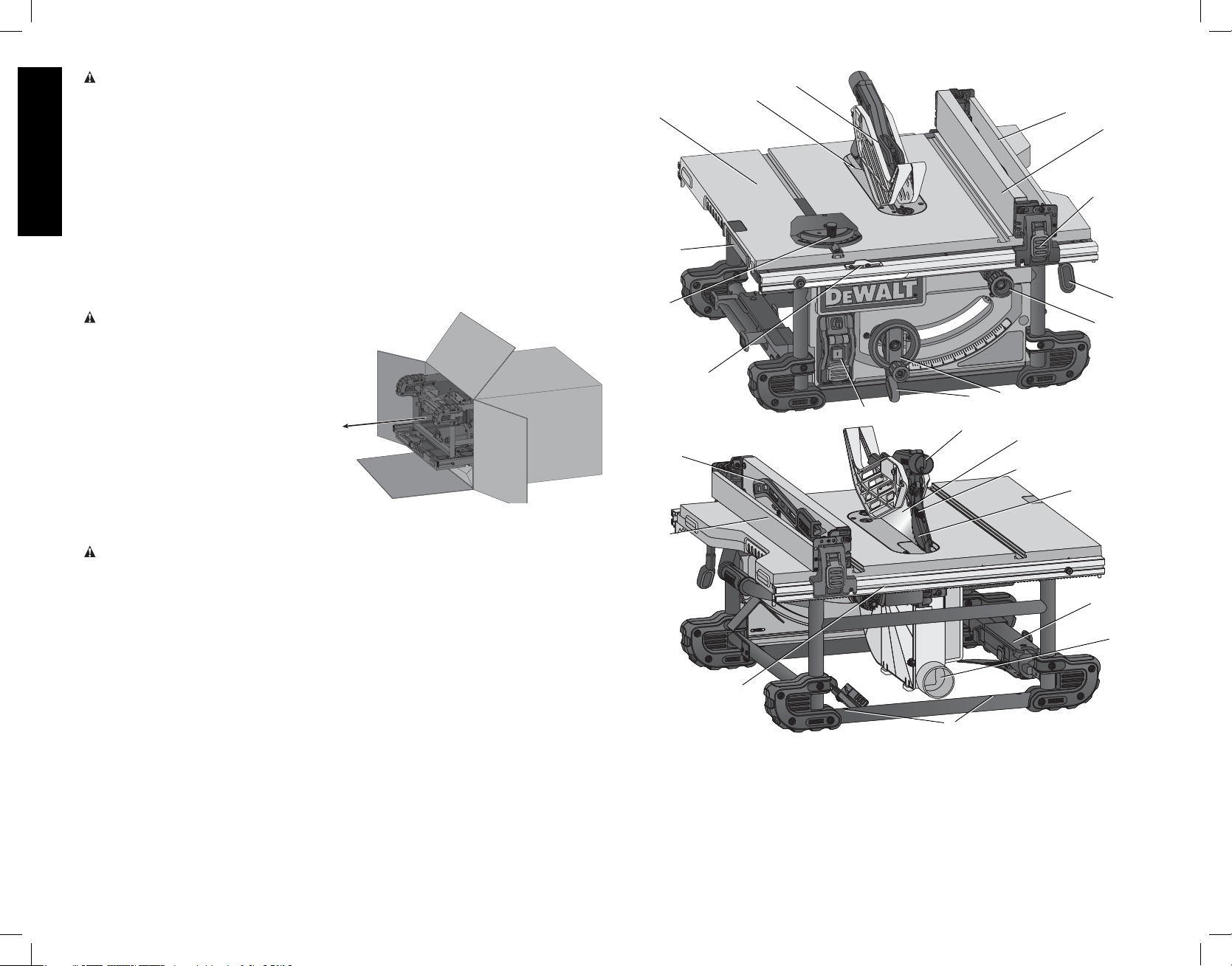
FEATURES (Fig. 2, 3)
WARNING: Never modify the power tool or any part of it. Damage or personal injury could
result.
Examine Figures 2 and 3 to become familiar with the saw and its various parts. The following
sections on assembly and adjustments will refer to these terms and you must know what and
where the parts are.
A. Table
B. Blade
C. Rip scale indicator
D. Fine adjust knob
E. Rail lock lever
F. Blade height adjustment wheel
G. Bevel lock lever
H. ON/OFF switch
I. Mounting holes
J. Miter gauge
K. Blade guard assembly
L. Riving knife/blade guard release lever
M. Splitter
N. Anti-kickback assembly
O. Dust collection port
P. Guard dust collection port
Q. Throat plate
R. Rip fence
S. Rip fence latch
T. Work support/narrrow rip fence (shown
in stored position)
U. Blade wrenches (stored position)
V. Push stick (stored position)
W. Riving knife (non thru sawing) (FIG. 27)
FIG. 2
A
L
J
C
FIG. 3
V
T
S
K
Q
F
G
H
P
I
B
M
T
R
S
E
D
N
U
O
INTENDED USE
This table saw is designed for professional ripping, crosscutting, mitering, beveling and non
thru-cutting applications, such as dadoing, with various materials.
DO NOT use for cutting metal, cement board, or masonry.
DO NOT use under wet conditions or in presence of flammable liquids or gases.
DO NOT let children come into contact with the tool. Supervision is required when
inexperienced operators use this tool.
4
Page 7
ASSEMBLY
WARNING: Shock Hazard. To reduce the risk of serious personal injury, turn unit
off and disconnect machine from power source before attempting to move it, change
accessories or make any adjustments. An accidental start-up can cause injury.
THIS SAW SHOULD BE ASSEMBLED IN THE FOLLOWING ORDER: (FIG, 2, 4)
1. Make sure blade is installed correctly and arbor nut is tight. Use wrenches (U) stored on
the tool. Refer to Figure 3.
2. Install and lock throat plate (Q). (NOTE: Adjust leveling screws before proceeding. Refer
to To Assemble the Throat Plate.)
3. Attach the rip fence (R). (NOTE: Adjust rip scale before proceeding. Refer to Adjusting
Rip Scale.)
4. Position the blade guard assembly.
5. Attach anti-kickback assembly to the guard assembly.
NOTE: To attach this table saw to a stand, please follow the instructions included with the
stand assembly.
Tools needed for assembly include the wrenches included with this saw.
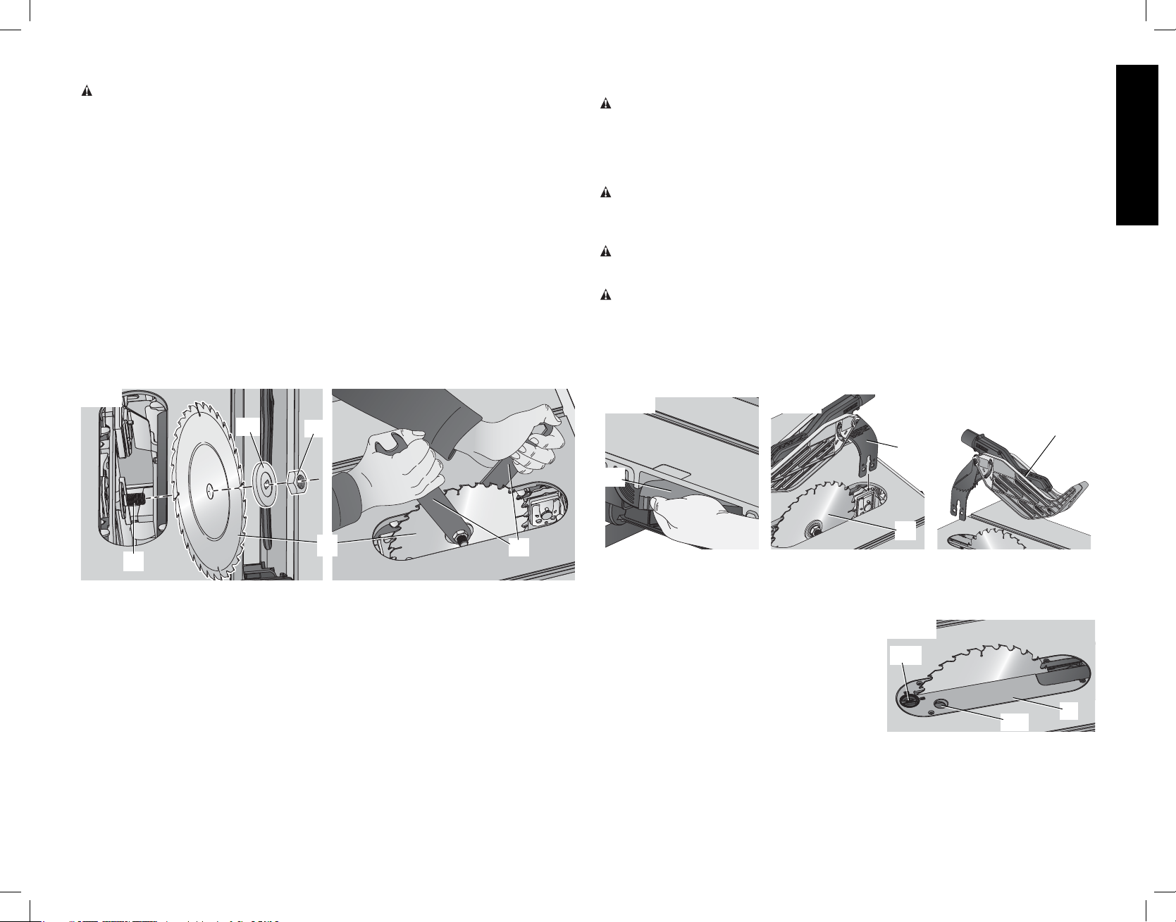
ATTACHING/REPLACING THE BLADE (FIG. 2, 4)
1. Raise the saw blade arbor to its maximum height by turning the blade height adjustment
wheel (F) clockwise.
2. Remove the arbor nut (X) and flange (AA) from the saw arbor by turning counterclockwise.
FIG. 4
AA
X
POSITIONING THE BLADE GUARD ASSEMBLY/RIVING KNIFE (FIG. 5, 6)
To position the blade guard assembly:
WARNING: Use the blade guard assembly for all thru-sawing.
1. Raise the saw blade arbor to its maximum height.
2. Install blade guard assembly by pulling the riving knife/guard release lever (L) and inserting
splitter (M) until it bottoms out.
3. Release lever, make sure clamp plates are fully closed and the splitter is clamped securely.
NOTE: Pull on the blade guard assembly/riving knife to ensure it has locked into place.
WARNING: Use the riving knife for non thru-sawing when blade guard assembly cannot
be used.
NOTE: Follow steps 1–3 to install the riving knife (W) in the same manner as the blade guard
assembly, Refer to figure 24.
WARNING: Before connecting the table saw to the power source or operating the saw,
always inspect the blade guard assembly and riving knife for proper alignment and clearance
with saw blade. Check alignment after each change of bevel angle.
WARNING: To reduce the risk of serious personal injury, DO NOT operate saw if riving knife
or blade guard assembly is not securely clamped in place.
When properly aligned, the blade guard assembly/riving knife will be in line with the blade at
both table top level, and at the top of the blade. Using a straight edge, ensure that the blade
(B) is aligned with the riving knife (W) or the splitter (M). With power disconnected, operate the
blade tilt and height adjustments through the extremes of travel and ensure the blade guard
assembly clears the blade in all operations and that the anti-kickback assembly is functioning.
FIG. 5
FIG. 6
FIG. 7
K
M
L
English
B
Y
U
3. Place the saw blade on to the spindle (Y) making sure the teeth of the blade (B) point down
at the front of the table. Assemble the flange and arbor nut to the spindle and tighten arbor
nut (X) as far as possible by hand, making sure that the saw blade is against the inner washer
and the flange (AA) is against the blade. Ensure the largest diameter of the flange is against
the blade. Ensure the spindle and flange are free from dust and debris.
4. To keep the spindle from rotating when tightening the arbor nut, use the open end of the
wrench (U) to secure the spindle.
5. Using the arbor wrench, tighten the arbor nut (X) by turning it clockwise.
6. NOTE: Different types of blades make different kerfs (width of cuts). Therefore, it is
necessary to check adjustment of rip scale when changing blades. Replacement blade
MUST not exceed the thickness stated on the riving knife. The riving knife provided with
the saw is 2.2mm thick.
B
To remove the blade guard assembly/riving knife (FIG. 5, 7)
1. Pull the riving knife/guard release lever (L).
2. Lift up on blade guard assembly(K)/riving knife (W).
TO ASSEMBLE THE THROAT PLATE (FIG. 8)
1. Align the throat plate (Q) as shown in Figure 8,
FIG. 8
and insert the tabs on the back of the throat
plate into the holes on the back of the table
BB
opening.
2. Rotate cam counterclockwise until the front
of throat plate drops into place. Secure
by rotating cam lock knob (BB) clockwise
1/4 turn (when cam lock is under the table
CC
holding the throat plate in place).
3. The throat plate includes four adjustment screws which raise or lower the throat plate.
When properly adjusted, the front of the throat plate should be flush or slightly below the
surface of the table top and secured in place. The rear of the throat plate should be flush
or slightly above the table top.
5
Q
Page 8
TO REMOVE THE THROAT PLATE
151413 1817 20 21916
76510912 1118
1. Remove the throat plate (Q) by turning the cam lock knob (BB) 1/4 turn counterclockwise
2. Using finger hole (CC) on the plate, pull throat plate up and forward to expose the inside
of the saw. DO NOT operate the saw without the throat plate. If using dado blade, use
proper dado throat plate (sold seperately).
WARNING: To reduce the risk of serious personal injury, the throat plate must be locked in
place at all times.
English
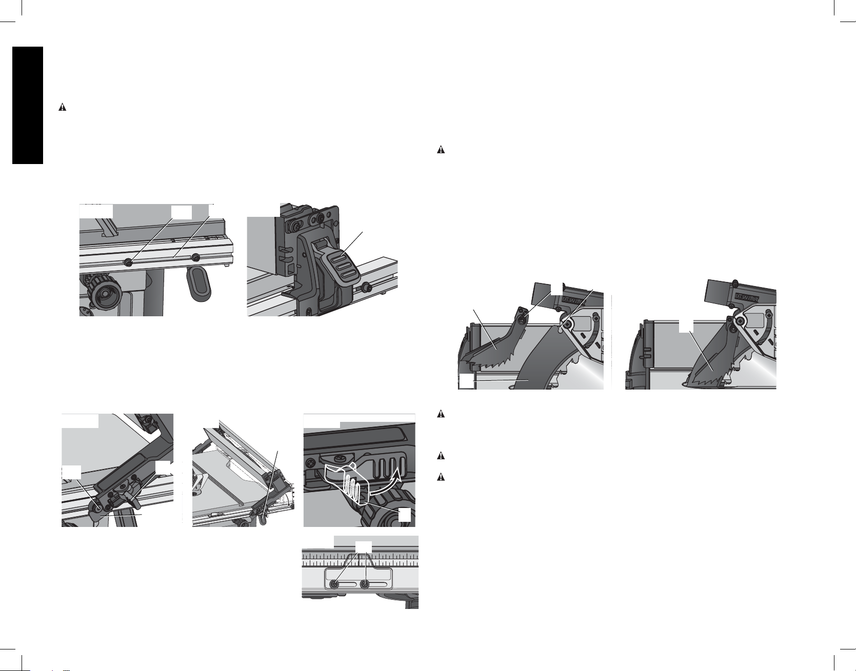
DWE7490 - ASSEMBLING THE RIP FENCE (FIG. 9, 10)
The rip fence can be installed in two positions on the right (position 1 for 0" to 24.5" ripping,
and position 2 for 4" to 28.5" ripping) and one position on the left of your table saw.
1. Align the locator pin (DD) on the fence rail with the fence head slot and align the latch (S)
with the opening (EE).
2. Secure the rip fence by snapping the latches onto the rails as shown in Figure 9. Be sure
to snap both front and rear latches (S) in place.
FIG. 9
DD
EE
FIG. 10
S
4. Loosen the rip scale indicator screws (GG) and set the rip scale indicator to read zero (0).
Retighten the rip scale indicator screws. The yellow rip scale (top) reads correctly only
when the fence is mounted on the right side of the blade and is in position 1 (for 0 to 24.5"
ripping) [not the 32" rip position]. The white scale (bottom) reads correctly only when the
fence is mounted on the right side of the blade and in position 2 (for 4" to 32.5" ripping).
NOTE: For the DWE7491 the white scale (bottom) reads correctly only when the fence is
mounted on the right side of the blade and in position 2 (for 8" to 28.5" ripping)
A metric scale is available at an additional cost, refer to Accessories for details.
ANTI-KICKBACK ASSEMBLY (FIG. 15, 16)
WARNING: To reduce the risk of serious personal injury, the anti-kickback assembly must
be in place for all possible cuts.
1. Remove the anti-kickback assembly (N) from the storage position. Refer to Storage.
2. Locate the anti-kickback mounting slot (HH) at the top of the splitter (M).
3. Align the stem (II) with the mounting slot. Depress the stem (II) and push down on the
anti-kickback assembly (N) until it snaps and locks into place. NOTE: Pull on the antikickback assembly to ensure it has locked into place.
4. To remove the anti-kickback assembly, depress the stem and pull up and out of the
mounting slot.
With power disconnected, operate the blade tilt and height adjustments through the extremes
of travel and ensure the blade guard assembly clears the blade in all operations and that the
anti-kickback assembly is functioning.
FIG. 15
II
HH
FIG. 16
N
DWE7491 - ASSEMBLING THE RIP FENCE (FIG. 11–13)
The rip fence can be installed in two positions on the right (Position 1 for 0" to 24.5" ripping, and
Position 2 for 8" to 32.5" ripping) and one position on the left of this saw.
1. Unlock the fence latches (S).
2. Holding the fence at an angle, align the locator pins (front and back) (DD) on the fence
rails with the fence head slots (FF) as shown in Figure 11.
3. Slide the head slots onto the pins and rotate the fence down untill it rests on the rails.
4. Lock the fence in place by closing the front and back latches (S) onto the rails.
FIG. 11
FIG. 12
FIG. 13
E
DD
S
FF
ADJUSTING THE RIP SCALE (FIG. 12, 14)
1. Unlock the rail lock lever (E).
FIG. 14
GG
2. Set the blade at 0° bevel and move the fence in until it
touches the blade.
3. Lock the rail lock lever.
N
M
Bench Mounting
WARNING: Before mounting to a bench or a stand, to reduce the risk of serious
personal injury, turn unit off and disconnect machine from power source before
attempting to move it, change accessories or make any adjustments. An accidental
start-up can cause injury.
CAUTION: To reduce the risk of personal injury, make sure table saw is firmly mounted to
a stable surface or stand provided before use.
CAUTION: Ensure that the surface is stable enough that large pieces of material will not
cause it to tip over during use.
The table saw must be mounted firmly. The mounting surface must have a 15" by 15" (38
S
x 38cm) opening to allow dust to escape.
Four holes (I) are provided in the tool’s base for mounting. We strongly recommend that these
holes be used to anchor the table saw to your workbench or other stationary rigid frame.
1. Center the saw on a square piece of 1/2" (12.7mm) plywood. The plywood must have a
15" x 15" (38 x 38 cm) opening to allow dust to escape.
2. Mark the positions of the two rear mounting holes (spaced 8-5/8" [220 mm] apart) in the
frame of the saw with a pencil. Then measure forward 19-5/8" (498.5 mm) the two front
holes.
3. Remove the saw and drill 5/16" (7.9 mm) holes in the places you have just marked.
6
Page 9
4. Position the saw over the four holes you drilled in the plywood and insert four 1/4"
(6.4mm) machine screws FROM THE BOTTOM. Install washers and 5/16" (7.9 mm) nuts
on the top. Tighten securely.
5. In order to prevent the screw heads from marring the surface to which you clamp the saw,
attach two strips of scrap wood to the bottom of the plywood base. These strips can
be attached with wood screws installed from the top side as long as they don’t protrude
through the bottom of the strip.
6. Use a “C” clamp to secure the plywood base to your workbench whenever you use the
saw.
Connecting Saw to Power Source
WARNING: To reduce the risk of injury, before connecting saw to power source, make
sure the switch is in the OFF position.
Be sure your power supply agrees with the name plate marking. AC ONLY means that this
saw will operate on alternating current only. A voltage decrease of 10 percent or more will
cause a loss of power and overheating. All D
EWALT tools are factory tested. If this tool does
not operate, check the power supply.
ADJUSTMENTS
WARNING: To reduce the risk of injury, turn unit off and disconnect machine from
power source before installing and removing accessories, before adjusting or changing set-
ups or when making repairs. An accidental start-up can cause injury.
NOTE: This saw is fully and accurately adjusted at the factory at the time of manufacture. If
readjustment due to shipping and handling or any other reason is required, follow the sections
below to adjust this saw.
Once made, these adjustments should remain accurate. Take a little time now to follow these
directions carefully to maintain the accuracy of which this saw is capable.
RAIL LOCK ADJUSTMENT (FIG. 2, 17)
(Tightening Fence Clamping System)
1. Lock the rail lock lever (E).
2. On the underside of the saw, loosen the jam nut (JJ).
3. Tighten the hex rod (KK) until the spring on the locking
system is compressed creating the desired tension on the
rail lock lever. Retighten the jam nut against the hex rod.
4. Check that the fence does not move when the lock lever is
engaged. If the fence is still loose, tighten the spring further.
RIP SCALE ADJUSTMENT
See Adjusting the Rip Scale under Assembly.
BLADE ALIGNMENT ADJUSTMENT (FIG. 18)
(Blade Parallel to Miter Slot)
WARNING: Cut Hazard. Check the blade at 0˚ and 45˚ to
make sure blade does not hit the throat plate, causing personal
injury.
If the blade appears to be out of alignment with the miter slot on
the table top, it will require calibration for alignment. To realign the
blade and miter slot, use the following procedure:
WARNING: To reduce the risk of injury, turn unit off and
disconnect machine from power source before installing and
removing accessories, before adjusting or changing set-ups or
when making repairs. An accidental start-up can cause injury.
FIG. 17
FIG. 18
KK
JJ
LL
1. Using a 6mm hex wrench, loosen rear pivot bracket fasteners (LL) just enough to allow
the bracket to move side-to-side.
2. Adjust the bracket until the blade is parallel to the miter gauge slot.
3. Tighten the rear pivot bracket fasteners to 110–120 in-lbs (12.5–13.6 Nm).
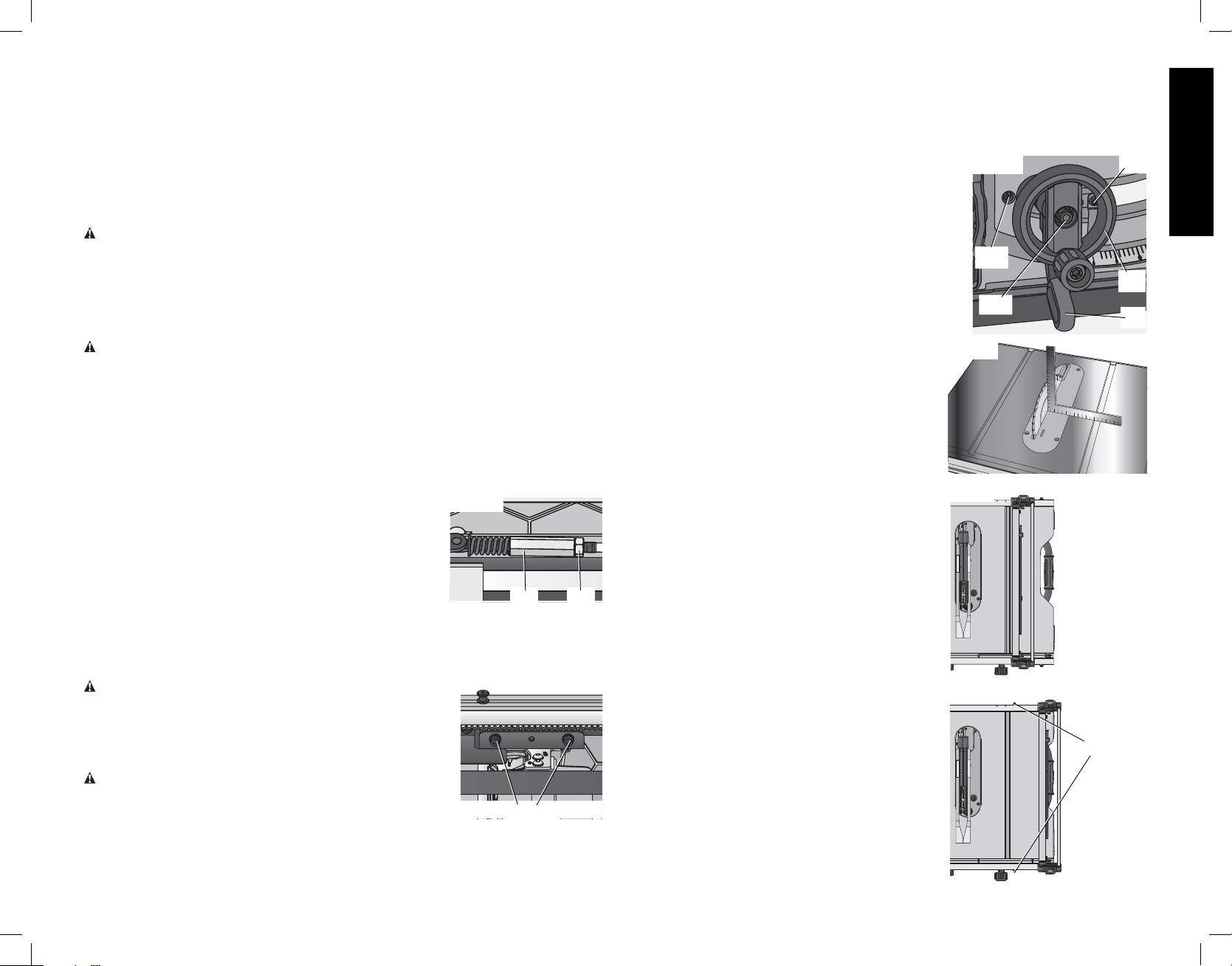
BEVEL STOP AND POINTER ADJUSTMENT (FIG. 19, 20)
1. Raise the blade fully by rotating the blade height
adjustment wheel (F) clockwise until it stops.
FIG. 19
OO
2. Unlock the bevel lock lever (G) by pushing it up and to
the right. Loosen the bevel stop screw (NN).
3. Place a square flat against the table top and against the
blade between teeth, as shown in Figure 20. Ensure the
bevel lock lever is in its unlocked, or up, position.
4. Using the bevel lock lever, adjust the bevel angle until it
is flat against the square.
5. Tighten the bevel lock lever by pushing it down.
6. Turn the bevel stop cam (MM) until it firmly contacts the
bearing block. Tighten the bevel stop screw (NN).
7. Check the bevel angle scale. If the pointer does not
read 0°, loosen pointer screw (OO) and move the
NN
F
MM
G
FIG. 20
pointer so it reads correctly. Retighten the pointer
screw.
8. Repeat at 45°, but do not adjust pointer.
MITER GAUGE ADJUSTMENT (FIG. 2)
To adjust miter gauge (J) loosen knob, set to desired
angle and tighten knob.
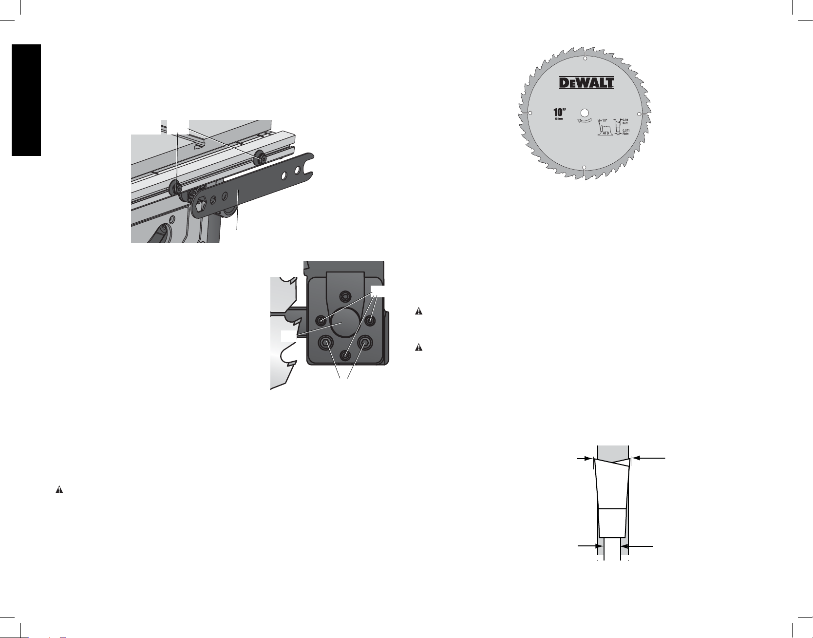
FENCE ALIGNMENT ADJUSTMENT (FIG. 2, 21)
(Blade Parallel to Fence)
If you experience fence alignment problems and want
FIG. 21
to correct an out of parallel alignment between the
fence and the blade, be sure to check the alignment
of the blade to the miter slot first. After confirming that
those elements are aligned, proceed with alignment of
the blade to the fence using the following procedure:
POSITION 1
POSITION 1 FENCE ALIGNMENT (FIG. 21)
1. Install the fence in position 1 (Fig. 21) and unlock
the rail lock lever (E). Locate both locator pins (DD)
that support the fence on the front and rear rails.
2. Loosen the rear locator pin screw and adjust the
allignment of the fence in the groove until the
fence face is parallel to the blade. Make sure you
measure from the fence face to the front and back
FIG. 22
of the blade to ensure alignment.
3. Tighten the locator pin screw and repeat on the
left side of the blade.
DD
4. Check rip scale pointer adjustment.
POSITION 2
English
7
Page 10
POSITION 2 FENCE ALIGNMENT
(FIG. 22, 23)
1. To align position 2 fence locator pins, ensure position 1 pins have been aligned, refer to
Position 1 Fence Alignment.
2. Loosen the position 2 locator pins, then using the blade wrench holes as a guide for
positioning, align the pins (Fig. 23).
3. Tighten the locator pins (front and rear).
English
FIG. 23
DD
U
ALIGNING RIVING KNIFE TO BLADE (FIG. 24)
1. Remove the throat plate. Refer to Remove Throat
Plate under Assembly.
FIG. 24
2. Raise the blade to full depth of cut and 0° bevel
angle.
3. Locate the three small set screws (PP) adjacent to
the riving knife lock knob (QQ). These screws will
be used to adjust the riving knife position.
4. Lay a straight edge on the table against two blade
tips. The riving knife should not touch the straight
QQ
edge. If needed, loosen the two larger lock screws
(RR).
5. Adjust the small set screws (PP) to move the riving
knife according to the position noted in step 5. Lay
RR
the straight edge on the opposite side of the blade
and repeat adjustments as needed.
6. Lightly tighten the two larger lock screws (RR).
7. Place a square flat against the riving knife to verify the riving knife is vertical and in-line with
the blade.
8. If needed, use the set screws to bring the riving knife vertical with the square.
9. Repeat steps 5 and 6 to verify position of riving knife.
10. Fully tighten the two larger lock screws (RR).
Saw Blades (Fig. 25)
WARNING: Riving knives must be matched to saw blade dimensions in order to function
effectively. Refer to Riving Knife Selection.
NOTE: THIS SAW IS INTENDED FOR USE ONLY WITH SAW BLADES 10" (254 mm) IN
DIAMETER.
PP
FIG. 25
• The saw blade furnished with your new saw is a 10" (254mm) combination blade, used
for crosscutting (across the grain) and ripping (with the grain) through the material. The
center hole to fit on the arbor is 5/8" (16mm) diameter. This blade will produce a good
quality cut for most applications.
• There are many types of blades available to do specific and special jobs such as cross
cut only, rip only, hollow ground, thin plywood, paneling, etc.
• Use only saw blades designed for maximum safe operating speeds of 5,000 RPM or
greater.
• Saw blades should always be kept sharp. It is recommended that you locate a
reputable sharpening service to sharpen your blades when needed.
• Never stack blades on top of one another to store. Place material such as cardboard
between them to keep the blades from coming in contact with one another.
CAUTION: To reduce the risk of injury, abrasive wheels or blades (including diamond)
should not be used on this saw.
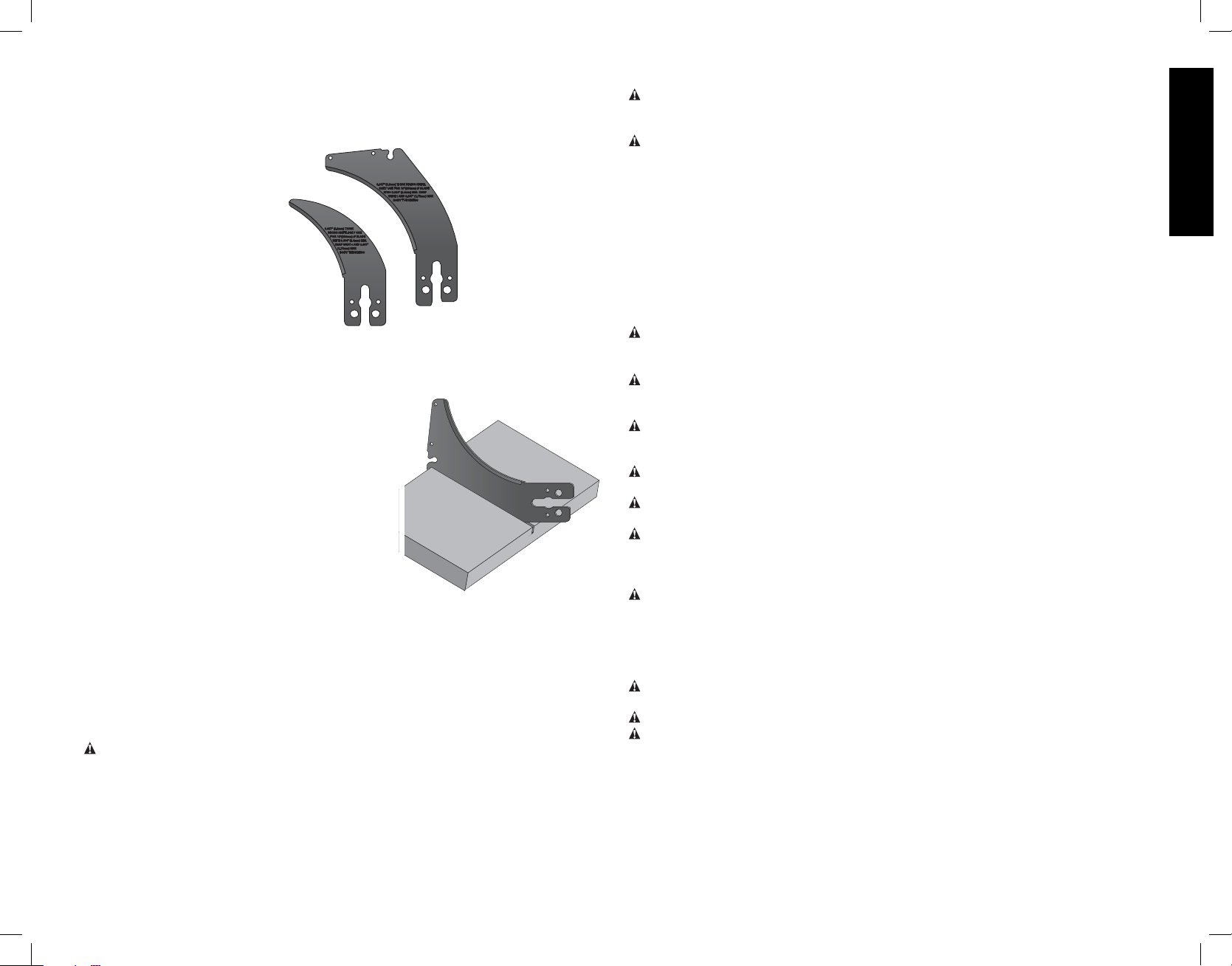
Splitter and Riving Knife Selection (Fig. 26–28)
WARNING: To minimize the risk of kickback and to ensure proper cutting, the splitter and
riving knife must be the proper thickness for the blade used.
The splitter and riving knife supplied with this table saw is the correct size for the blade
supplied with the saw.
If a different blade is used, check the blade body (plate) thickness and the blade kerf (cutting)
width marked on the blade or on the blade packaging. The splitter and riving knife thickness
must be greater than the body thickness and less than the kerf width as shown in Figure 26.
FIG. 26
KERF WIDTH
(WIDTH OF CUT
MADE BY THE
BLADE)
BODY (OR PLATE)
THICKNESS OF THE
BLADE
RIVING KNIFE
THICKNESS
8
Page 11
The riving knife provided with this saw is marked as follows (Fig. 27):
0.087" (2.2mm) THICK RIVING KNIFE. ONLY USE FOR 10" (254mm) Ø BLADE WITH
0.094" (2.4 mm) MIN. KERF WIDTH AND 0.067" (1.75mm) MAX. BODY THICKNESS.
FIG. 27
All DEWALT blade body thickness and kerf widths are provided at www.dewalt.com.
If a different blade is used and the body thickness
and kerf width dimensions are not provided, use the
following procedure to determine the correct riving
knife thickness:
1. Measure the body thickness of the blade.
2. Make a shallow cut in scrap material and measure
the kerf width.
3. Select the riving knife (Fig. 28).
4. Slide the riving knife through the shallow cut
made in step 2 to confirm the correct riving knife
has been selected. The riving knife should not
bind or drag through the cut (Fig. 28).
IMPORTANT: If any dragging or binding of the
material is encountered as it reaches the riving knife,
turn unit off and disconnect machine from power
source. Repeat steps 1–4 to make the proper riving
knife selection before attempting another cut.
FIG. 28
Kickback
Kickback is a dangerous condition! It is caused by the workpiece binding against the blade.
The result is that the workpiece can move rapidly in a direction opposite to the feed direction.
During kickback, the workpiece could be thrown back at the operator. It can also drag
the operator’s hand back into the blade if the operator’s hand is at the rear of the blade. If
kickback occurs, turn the saw OFF and verify the proper functioning of the riving knife, antikickback assembly and blade guard assembly before resuming work.
WARNING: See Additional Safety Rules for Table Saws and follow all warnings
provided regarding KICKBACK.
OPERATION
WARNING: To reduce the risk of injury, turn unit off and disconnect machine
from power source before installing and removing accessories, before adjusting or
changing set-ups or when making repairs. An accidental start-up can cause injury.
WARNING: Before using the saw, verify the following each and every time:
• ALWAYS wear proper eye, hearing and respiratory equipment.
• Blade is tight.
• Bevel angle and height lock knobs are tight.
• If ripping, ensure fence lock lever is tight and fence is parallel to the blade.
• If crosscutting, miter gauge knob is tight.
• The blade guard assembly is properly attached and the anti-kickback assembly is
functioning.
• ALWAYS inspect the blade guard assembly and riving knife for proper alignment, operation
and clearance with saw blade.
• ALWAYS make sure both guards are in the down position in contact with the table before
operating.
WARNING: To reduce the risk of serious personal injury, have push stick ready to use
before starting cut.
Failure to adhere to these common safety rules can greatly increase the likelihood of injury.
WARNING: To reduce the risk of injury, turn unit off and disconnect machine from
power source before installing and removing accessories, before adjusting or changing set-
ups or when making repairs. An accidental start-up can cause injury.
WARNING: Before connecting the table saw to the power source or operating the saw,
always inspect the blade guard assembly and riving knife for proper operation alignment and
clearance with saw blade. Personal injury may result.
WARNING: Ripping or crosscutting may cause saw to tip over while operating. Make sure
saw is securely mounted to a stable surface.
WARNING: Never use the fence and miter gauge together. This may cause a kickback
condition and injure the operator.
CAUTION: If this saw makes an unfamiliar noise or if it vibrates excessively, cease
operating immediately, turn unit off and disconnect from power source until the problem has
been located and corrected. Contact a D
service center or other qualified service personnel if the problem cannot be found.
CAUTION: The proper throat plate must be in place at all times to reduce the risk of a
thrown workpiece and possible injury.
There are two basic types of cutting with table saws: ripping and crosscutting. Regardless
of material, man made or natural wood, the distinction between ripping and crosscutting
is as follows: Ripping is cutting to a different width (usually with the grain) and crosscutting
describes cutting material across the shorter dimension (usually against the grain).
WARNING: When ripping, always use the fence to provide a guide for the material and
blade guard assembly to protect against a kickback situation.
WARNING: Never perform any cutting operation free hand. Never perform plunge cutting.
CAUTION: When crosscutting, always use the miter gauge.
EWALT factory service center, a DEWALT authorized
English
9
Page 12
On-Off Switch (Fig. 29)
WARNING: To reduce the risk of injury, be sure the switch
is in the OFF position before plugging machine in.
Push green button (H) in to turn this saw on and push down the
red paddle to turn this saw off.
LOCK OFF FEATURE INSTRUCTIONS
A cover above the switch folds down for insertion of a padlock
English
to lock the saw off. A padlock with a maximum diameter of
1/4" (6.35 mm) and minimum clearance of 3" (76.2 mm) is
recommended.
FIG. 29
Guard Operating Feature (Fig. 30)
WARNING: To reduce the risk of injury, turn unit off and disconnect machine from
power source before installing and removing accessories, before adjusting or changing set-
ups or when making repairs. An accidental start-up can cause injury.
1. The guard(s) will lock in place when in the raised position.
2. This feature increases visability when measuring the blade to fence distance.
3. Push down on guard(s) and they will release to the operating position.
NOTE: Pull on the anti-kickback assembly to ensure it is locked in place.
ALWAYS make sure both guards are in the down position in contact with the table before
operating.
FIG. 30
RAISED
POSITION
OPERATING
POSITION
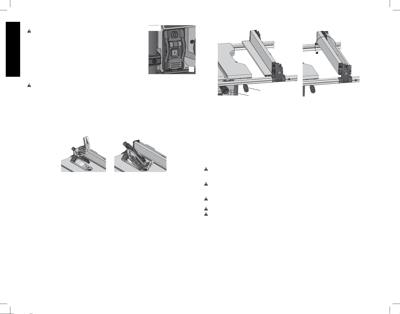
Rip Fence Operation (Fig. 31, 32)
RAIL LOCK LEVER (FIG. 31)
The rail lock lever (E) locks the fence in place preventing movement during cutting. To lock
the rail lever, push it down and toward the rear of the saw. To unlock, pull it up and toward
the front of the saw.
NOTE: When ripping, always lock the rail lock lever.
WORK SUPPORT EXTENSION/NARROW RIPPING FENCE
The table saw is equipped with a narrow ripping fence that also supports work that extends
beyond the saw table.
To use the narrow ripping fence in the work support position, rotate it from its stored position
as shown in Figure 32, and slide the pins into the lower sets of slots on both ends of the fence.
To use the narrow ripping fence in the narrow ripping position, snap the pins into the upper
sets of slots on both ends of the fence.
This feature will allow 2" (51 mm) of extra clearance to the blade. If more clearance is
necessary, follow directions for making an auxiliary fence under Narrow Rip Auxiliary Fence
in the Operation section.
NOTE: When not in use, the narrow ripping fence should be placed in its stored position.
FIG. 31
H
E
D
NOTE: This fence will allow the guard to remain on the saw when completing narrow ripping.
This fence will provide ample space for a push stick. If you prefer more clearance for push
blocks or push sticks, refer to Narrow Rip Auxiliary Fence.
FINE ADJUSTMENT KNOB (FIG. 31)
The fine adjustment knob (D) allows smaller adjustments when setting the fence. Before
adjusting, be sure the rail lock lever is in its up or unlocked position.
RIP SCALE POINTER
The rip scale pointer will need to be adjusted for proper performance of the rip fence if the
user switches between thick and thin kerf blades. The rip scale pointer only reads correctly
for position 1 (0 to 24.5"), however for position 1 with narrow rip fence in use add 2" (50 mm).
See Adjusting the Rip Scale under Assembly.
FIG. 32
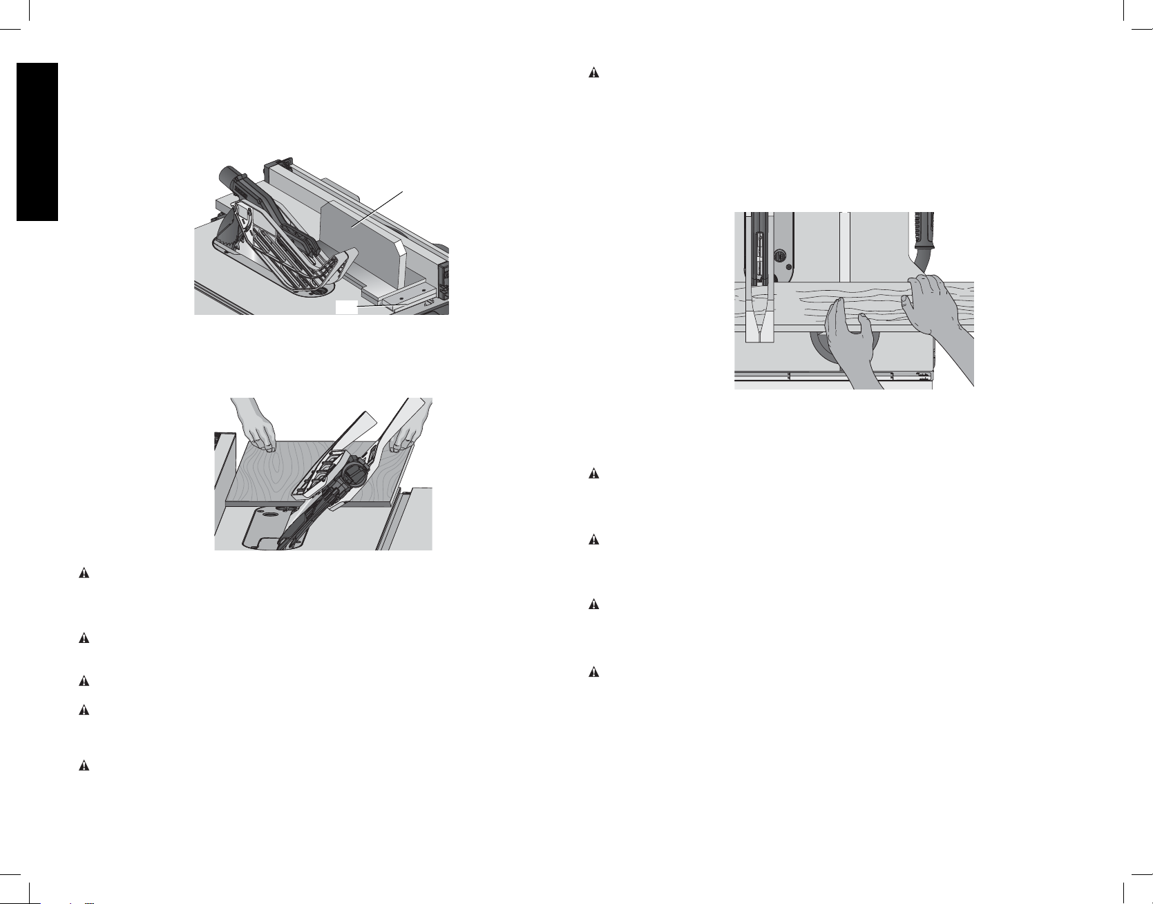
Ripping (Fig. 33)
WARNING: Never touch the “free end” of the workpiece or a “free piece” that is cut off,
while the power is ON and/or the saw blade is rotating. Piece may contact the blade resulting
in a thrown workpiece and possible injury.
WARNING: A rip fence should ALWAYS be used for ripping operations to prevent loss of
control and personal injury. NEVER perform a ripping operation freehand. ALWAYS lock the
fence to the rail.
WARNING: When bevel ripping and whenever possible, place the fence on the side of the
blade so that the blade is tilted away from the fence and hands.
WARNING: Keep hands clear of the blade.
WARNING: Use a push stick to feed the workpiece if there is 2–6" (51–152mm) between
the fence and the blade. Use a narrow ripping fence feature and push block to feed the
workpiece if there is 2" (51mm) or narrower between the fence and the blade.
1. Lock the rip fence by pressing the rail lock lever down. Remove the miter gauge.
2. Raise the blade so it is about 1/8" (3.2mm) higher than the top of the workpiece.
3. Hold the workpiece flat on the table and against the fence. Keep the workpiece about 1"
(25.4mm) away from the blade.
10
Page 13
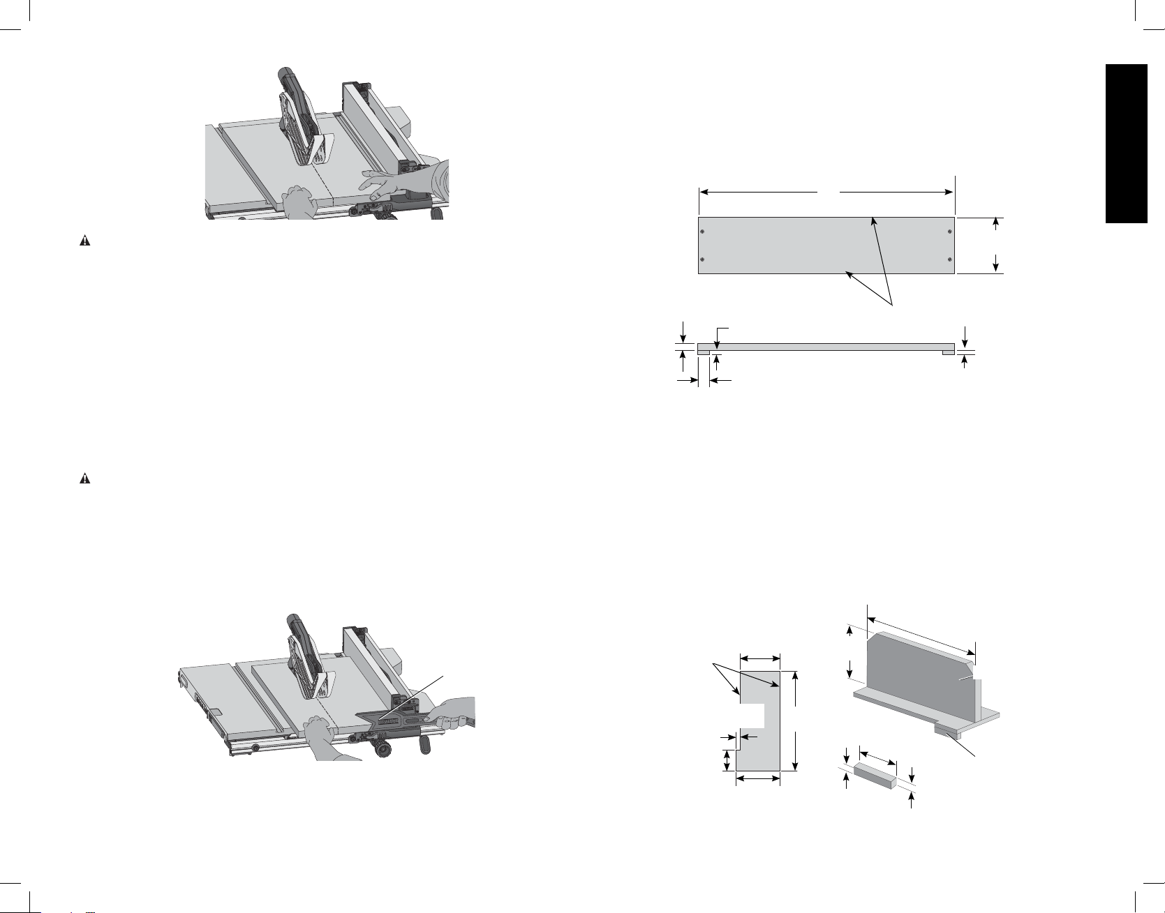
FIG. 33
Narrow Rip Auxiliary Fence (Fig. 35, 36)
The narrow rip auxiliary fence should be used for a rip measuring 2" (51mm) or narrower. This
fence will allow the guard to remain on the saw when completing narrow ripping. This fence
will provide ample space for proper use of a push block (TT, see Push Block).
1. Follow the diagram in Fig. 35 to construct the narrow rip auxiliary fence (SS).
NOTE: The length should be cut to fit the length of the saw table top and sides (TT) must be
parallel.
FIG. 35
SS
English
CAUTION: The workpiece must have a straight edge against the fence and must not be
warped, twisted or bowed. Keep both hands away from the blade and away from the path of the
blade. See proper hand position in Figure 33.
4. Turn the saw on and allow the blade to come up to speed. Both hands can be used in
starting the cut. When there is approximately 12" (305mm) left to be ripped, use only one
hand, with your thumb pushing the material, your index and second finger holding the
material down and your other fingers hooked over the fence. Always keep your thumb
along side your first two fingers and near the fence.
5. Keeping the workpiece against the table and fence, slowly feed the workpiece rearward
all the way through the saw blade. Continue pushing the workpiece until it is clear of the
blade guard assembly and it falls off the rear of the table. Do not overload the motor.
6. Never try to pull the workpiece back with the blade turning. Turn the switch off, allow the
blade to stop, raise the anti-kickback teeth on each side of the riving knife if necessary
and slide the workpiece out.
7. When sawing a long piece of material or a panel, always use a work support. A sawhorse,
rollers, or out feed assembly provides adequate support for this purpose. The work
support must be at the same height or slightly lower than the saw table.
CAUTION: Never push or hold onto the free or cut-off side of the workpiece if it is between
the blade and the fence.
Ripping Small Pieces (Fig. 34)
It is unsafe to rip small pieces. It is not safe to put your hands close to the blade. Instead, rip
a larger piece to obtain the desired piece. When a small width is to be ripped and the hand
cannot be safely put between the blade and the rip fence, use one or more push sticks. A
pattern is included at the end of this manual to make push sticks. A push stick (V) is included
with this saw, attached to the rip fence. Use the push stick(s) to hold the workpiece against
the table and fence, and push the workpiece fully past the blade.
FIG. 34
V
4-3/4"
(121 mm)
1/2"
(12.7 mm)
3/8"
(9.5 mm)
1"
(25 mm)
TT
3/8"
(9.5mm)
2. After the narrow rip auxiliary fence is constructed, slip it over the saw table top and place
it flush to the fence as shown in Figure 37.
3. Feed the workpiece through until the edge of the material reaches the front edge of the
saw table top.
4. Continue feeding the material using the push block (UU) until the cut is complete.
Push Block (Fig. 36, 37)
IMPORTANT: Only use the push block (UU) with the narrow rip auxiliary fence, refer to
Narrow Rip Auxiliary Fence. The push block should be used once the material being cut
reaches the saw table top.
1. Construct a push block using the diagram in Figure 36.
NOTE: Edges (V V) must be the same size.
IMPORTANT: The over hanging edge (V V, Fig. 36) MUST be square. An uneven lip could
cause the push block to slip or push the material away from the fence.
FIG. 36
V V
4-3/4"
(121 mm)
5"
(127 mm)
12
"
(305mm)
UU
11
2-1/2"
(64 mm)
1/2"
(12.7 mm)
5-1/4"
(133 mm)
12"
(305 mm)
2-1/2" (64mm)
1/2"
(12.7 mm)
WW
1/2"
(12.7 mm)
Page 14
2. Place the push block (UU, Fig. 37) behind the material and ensure the lip of the block is
flush to the narrow rip auxiliary fence (SS).
3. Once the push block is in place, continue feeding the material until the cut is complete
making sure the push block remains flush to the narrow rip auxiliary fence at all times.
IMPORTANT: The narrow rip auxiliary fence and the over hanging edge (W W, Fig. 36) should
both be the same thickness.
FIG. 37
English
UU
SS
Bevel Ripping
This operation is the same as ripping except the bevel angle is set to an angle other than zero
degrees. For proper hand position, Refer to figure 38.
FIG. 38
WARNING: Before connecting the table saw to the power source or operating the saw,
always inspect the blade guard assembly and riving knife for proper alignment and clearance
with saw blade. Check alignment after each change of bevel angle.
Crosscutting
WARNING: NEVER touch the “free end” of the workpiece or a “free piece” that is cut off,
while the power is ON and/or the saw blade is rotating. Piece may contact the blade resulting
in a thrown workpiece and possible injury.
WARNING: To reduce the risk of injury, NEVER use the fence as a guide or length stop
when crosscutting.
WARNING: NEVER use a length stop on the free end of the workpiece when crosscutting.
In short, the cut-off piece in any thru-sawing (cutting completely through the workpiece)
operation must never be confined — it must be allowed to move away from saw blade to
prevent contact with blade resulting in a thrown workpiece and possibly injury.
WARNING: Use caution when starting the cut to prevent binding of the blade guard
assembly against the workpiece resulting in damage to saw and possible injury.
CAUTION: When using a block as a cut-off gauge, the block must be at least 3/4" (19mm)
thick and is very important that the rear end of the block be positioned so the workpiece is
clear of the block before it enters the blade to prevent contact with blade resulting in a thrown
workpiece and possibly injury.
1. Remove the rip fence and place the miter gauge in the desired slot.
2. Adjust the blade height so that the blade is about 1/8" (3.2mm) higher than the top of the
workpiece.
3. Hold the workpiece firmly against the miter gauge with the path of the blade in line with
the desired cut location. Keep the workpiece an inch or so in front of the blade. KEEP
BOTH HANDS AWAY FROM THE BLADE AND THE PATH OF THE BLADE (Fig. 39).
FIG. 39
4. Start the saw motor and allow the blade to come up to speed.
5. While using both hands to keep the workpiece against the face of the miter gauge, and
holding the workpiece flat against the table, slowly push the workpiece through the blade.
6. Never try to pull the workpiece with the blade turning. Turn the switch off, allow the blade
to stop, and carefully slide the workpiece out.
CAUTION: Never touch or hold onto the free or cut-off end of the workpiece.
Bevel Crosscutting
This operation is the same as crosscutting except that the bevel angle is set to an angle other
than 0°.
WARNING: Before connecting the table saw to the power source or operating the saw,
always inspect the blade guard assembly and riving knife for proper alignment and
clearance with saw blade. Check alignment after each change of bevel angle.
Mitering (Fig. 40)
WARNING: Miter angles greater than 45˚ may force the blade guard assembly into the saw
blade causing damage to the blade guard assembly and personal injury. Before starting the
motor, test the operation by feeding the workpiece into the blade guard assembly. If the blade
guard assembly contacts the blade, place the workpiece under the blade guard assembly, not
touching the blade, before starting the motor.
CAUTION: Certain workpiece shapes, such as molding may not lift the blade guard
assembly properly. Feed the workpiece slowly to start the cut. If the blade guard assembly
contacts the blade, place the workpiece under the blade guard assembly, not touching the
blade, before starting the motor.
This operation is the same as crosscutting except the miter gauge is locked at an angle other
than 0°. Hold the workpiece FIRMLY against the miter gauge (J) and feed the workpiece
slowly into the blade (to prevent the workpiece from moving).
12
Page 15
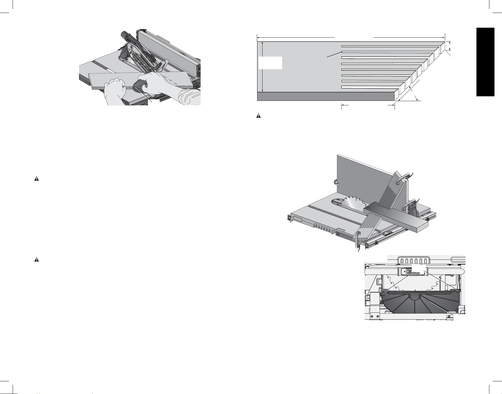
FIG. 40
J
Miter Gauge Operation
To set your miter gauge:
1. Loosen the miter gauge lock handle.
2. Move the miter gauge to the desired angle.
3. Tighten the miter gauge lock handle.
COMPOUND MITERING
This is a combination of bevel crosscutting and mitering. Follow the instructions for both bevel
crosscutting and mitering.
Dado Cutting
CAUTION: Do not attempt to stack dado blades thicker than 13/16" (20mm). Do not use
dado blades larger than 8" (200mm) diameter.
Since dado cuts are not thru-cuts, the cuts must be performed with the blade guard
assembly removed. To remove the blade guard assembly, pull riving knife/blade
guard release lever and pull up on the guard or riving knife to remove.
When using the dado, the special dado insert (also sold as an accessory) must be used.
Anytime a cut is required that is considerably wider than the saw kerf, a dado is used. A dado
cut is commonly used to add support and line up a shelf for a cabinet, bookcase or some
such project. When using the dado, the blade guard assembly must be removed. Use
EXTREME care when using the dado without the blade guard assembly and riving
knife. If a deep cut is required, use several successive passes rather than attempting to make
it with one pass. Maximum dado width on this saw is 13/16" (20mm). DO NOT USE WIDER
COMBINATIONS.
CAUTION: Always check dado blade clearance before plugging in the saw.
Be sure to place the blade guard assembly and standard throat plate back in
position and check adjustments when the dado cuts are complete. Reinstall blade
guard assembly, anti-kickback assembly and riving knife.
Featherboard Construction (Fig. 41, 42)
Featherboards are used to keep the work in contact with the fence and table, and help
prevent kickbacks. Dimensions for making a typical featherboard are shown in Figure 41.
Make the featherboard from a straight piece of wood that is free of knots and cracks. Clamp
the featherboard to the fence and table so that the leading edge of the featherboard will
support the workpiece until the cut is complete (Fig. 42). An 8" (203mm) high flat board can
be clamped to the rip fence and the featherboard can be clamped to the 8" (203mm) high
board.
FIG. 41
4"
(102mm)
THE KERF
SHOULD BE
ABOUT 1/4"
(6.4mm) APART
24" (610mm)
3/4"
(20mm)
60º
5" (127mm)
WARNING: Use featherboards for all non thru-sawing operations where the blade guard
assembly, anti-kickback assembly and riving knife cannot be used. Always replace the
blade guard assembly, anti-kickback assembly and riving knife when the non thrusawing operation is complete. Make sure the featherboard presses only on the portion of
the workpiece in front of the blade.
FIG. 42
Dust Collection (Fig. 43)
This table saw is equipped with a dustshroud
and dust collection port. For best results,
FIG. 43
YY
connect a vacuum to the port at the rear of
the saw and on the guard using a Y connector.
After extended use, the saw’s dust collection
system may become clogged. To clear the
dust collection system:
1. Unplug the saw.
2. Turn the saw on its side, so the bottom,
open part of the unit is accessible.
XX
3. Open the dust access door (XX) shown in Figure 43 by pressing the the side clips (YY).
Clean out the excess dust, and re-secure by pushing the side clips completely into place.
English
13
Page 16
Motor Overload and Power Loss Reset Switch
If power is interrupted by a circuit breaker trip, or power is lost, the saw contains a power loss
reset switch feature that will automatically reset to OFF position.
Circuit breaker overload is often the result of a dull blade. Change your blade on a regular
basis to avoid tripping your breaker. Disconnect the saw from power source and check your
blade before re-setting the circuit breaker and continuing to saw.
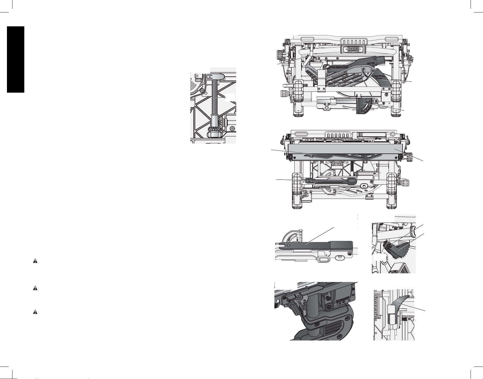
Lubrication (Fig. 44)
English
FIG. 44
1. All motor bearings are permanently lubricated at the factory and
no additional lubrication is needed.
2. The height adjustment screw may require periodic cleaning and
lubrication. If you have difficulty raising or lowering the blade:
a) Unplug the saw.
b) Turn the saw on its side, so the bottom, open part of the unit
is accessible.
c) Clean and lubricate the height adjustment screw threads (ZZ)
on the underside of this saw with general purpose grease.
Refer to Figure 44.
STORAGE (Fig. 45–50)
1. Attach push stick (V) to fence.
2. Remove blade guard assembly (K). See Remove Blade Guard Assembly. Slide blade
guard assembly into holder as shown, then turn lever counterclockwise to lock.
3. Depress the stem on the anti-kickback assembly (N) to allow the assembly to slide from the
riving knife slot.
4. Position anti-kickback assembly into the storage hole as shown. While depressing stem (II)
slide the anti-kickback assembly across the storage bracket (A1) and release pin to lock into
place.
5. Slide blade wrenches (U) into pocket until yellow button aligns with hole to secure in place,
refer to Figure 47.
6. Insert guide bar of miter guage (J) into pocket, then pivot and snap in place (Fig. 45).
7. Wrap cord in this location (A2, Fig. 46).
8. Non thru-sawing riving knife (W) slides in place underneath the saw, below the cord wrap.
Refer to Figure 50.
9. To store fence (K), snap work support in stored position. Remove fence from rails. Reattach
fence upside down on left side of saw. Refer to Figure 46. DO NOT hook locator pins on left
side fence locator screws. These screws will align with clearance pocket on fence as shown.
Pivot fence lock latches to secure.
MAINTENANCE
WARNING: To reduce the risk of injury, turn unit off and disconnect machine from
power source before installing and removing accessories, before adjusting or
changing set-ups or when making repairs. An accidental start-up can cause injury.
Cleaning
WARNING: Blowing dust and chips out of the motor housing using clean, dry compressed
air is a necessary regular maintenance procedure. Dust and chips containing metal particles
often accumulate on interior surfaces and could create an electrical shock or electrocution if
not frequently cleaned out. ALWAYS WEAR SAFETY GLASSES.
CAUTION: When cleaning, use only a damp cloth on plastic parts. Many household
cleaners contain chemicals which could seriously damage plastic. Also, do not use gasoline,
turpentine, lacquer or paint thinner, dry cleaning fluids or similar products which may seriously
damage plastic parts. Never let any liquid get inside the tool; never immerse any part of the
tool into a liquid.
ZZ
FIG. 45
N
K
J
FIG. 46
V
R
A2
FIG. 47
U
FIG. 48
FIG. 49
II
N
A1
FIG. 50
W
14
Page 17
Accessories
WARNING: Since accessories, other than those offered by DEWALT, have not been tested
with this product, use of such accessories with this tool could be hazardous. To reduce the
risk of injury, only D
EWALT recommended accessories should be used with this product.
Recommended accessories, such as a metric rip scale, for use with your tool are available at
extra cost from your local dealer or authorized service center. If you need assistance in locating
any accessory, please contact D
MD 21286, call 1-800-4-D
EWALT Industrial Tool Co., 701 East Joppa Road, Baltimore,
EWALT (1-800-433-9258) or visit our website: www.dewalt.com.
Repairs
To assure product SAFETY and RELIABILITY, repairs, maintenance and adjustment (including
brush inspection and replacement) should be performed by a D
a D
EWALT authorized service center or other qualified service personnel. Always use identical
EWALT factory service center,
replacement parts.
Register Online
Thank you for your purchase. Register your product now for:
• WARRANTY SERVICE: Registering your product will help you obtain more efficient
warranty service in case there is a problem with your product.
• CONFIRMATION OF OWNERSHIP: In case of an insurance loss, such as fire, flood or
theft, your registration of ownership will serve as your proof of purchase.
• FOR YOUR SAFETY: Registering your product will allow us to contact you in the unlikely
event a safety notification is required under the Federal Consumer Safety Act.
Register online at www.dewalt.com/register.
Three Year Limited Warranty
DEWALT will repair, without charge, any defects due to faulty materials or workmanship for
three years from the date of purchase. This warranty does not cover part failure due to normal
wear or tool abuse. For further detail of warranty coverage and warranty repair information,
visit www.dewalt.com or call 1-800-4-D
apply to accessories or damage caused where repairs have been made or attempted by
others. This warranty gives you specific legal rights and you may have other rights which vary
in certain states or provinces.
In addition to the warranty, D
D
EWALT will maintain the tool and replace worn parts caused by normal use, for free, any time
EWALT tools are covered by our:
during the first year after purchase.
90 DAY MONEY BACK GUARANTEE
If you are not completely satisfied with the performance of your D
Nailer for any reason, you can return it within 90 days from the date of purchase with a receipt
for a full refund – no questions asked.
LATIN AMERICA: This warranty does not apply to products sold in Latin America. For
products sold in Latin America, see country specific warranty information contained in the
packaging, call the local company or see website for warranty information.
EWALT (1-800-433-9258). This warranty does not
1 YEAR FREE SERVICE
EWALT Power Tool, Laser, or
FREE WARNING LABEL REPLACEMENT: If your warning labels become illegible or are
missing, call 1-800-4-D
EWALT (1-800-433-9258) for a free replacement.
XXX
English
15
Page 18

Défi nitions: lignes directrices en
matière de sécurité
Les définitions ci-dessous décrivent le niveau de danger pour chaque mot-indicateur
employé. Lire le mode d’emploi et porter une attention particulière à ces symboles.
DANGER: indique une situation dangereuse imminente qui, si elle n’est pas évitée,
entraînera la mort ou des blessures graves.
AVERTISSEMENT : indique une situation potentiellement dangereuse qui, si elle
n’est pas évitée, pourrait entraîner la mort ou des blessures graves.
ATTENTION: indique une situation potentiellement dangereuse qui, si elle n’est pas
évitée, pourrait entraîner des blessures légères ou modérées.
AVIS : indique une pratique ne posant aucun risque de dommages corporels mais
qui par contre, si rien n’est fait pour l’éviter, pourrait poser des risques de dommages
matériels.
POUR TOUT COMMENTAIRE OU QUESTION RELATIF À CET OUTIL OU TOUT AUTRE
OUTIL D
EWALT, COMPOSEZ GRATUITEMENT LE: 1-800-4-DEWALT (1-800-433-9258).
AVERTISSEMENT : afin de réduire le risque de blessures, lire le mode d’emploi de
l’outil.
Règles de sécurité – Généralités
AVERTISSEMENT: lire ces directives avant toute utilisation. Tout manquement aux
directives suivantes pose des risques de choc électrique, d’incendie et/ou de blessure
grave.
CONSERVER CES CONSIGNES
AVERTISSEMENT: SE CONFORMER AUX NORMES DU CODE EN MATIÈRE DE
Français
CÂBLAGE et connexions électriques pour prévenir tout risque de décharge électrique ou
d’électrocution.
Double isolation
Si la scie a été conçue d’usine avec une double isolation, lire les consignes suivantes.
Ce symbole
les décharges électriques, les outils à double isolation sont complètement recouverts de deux
couches distinctes d’isolant électrique ou d’une double épaisseur de matière isolante. Les
outils possédant ce type d’isolation ne sont pas destinés à être mis à la terre. Par conséquent,
ils sont munis d’une fiche à deux broches permettant d’utiliser une rallonge ne nécessitant
aucune prise à la terre. Réparer ou remplacer immédiatement tout cordon endommagé ou
usé.
REMARQUE : le fait que cet outil soit muni d’une double isolation ne signifie pas que
l’utilisateur peut cesser de respecter les consignes de sécurité qui s’imposent. L’isolation offre
une protection supplémentaire contre les blessures causées par toute défaillance électrique
des systèmes d’isolation internes.
FICHES POLARISÉES
Pour réduire tout risque de choc électrique, cet outil est muni d’une fiche
polarisée (l’une des lames est plus large que l’autre), laquelle ne peut être
raccordée qu’à une prise polarisée et ce, dans un seul sens. Si la fiche ne
rentrait pas complètement dans la prise, inverser le sens de la fiche. Si la
fiche ne s’adapte toujours pas, faire appel à un électricien qualifié pour qu’il
installe la prise appropriée. Ne jamais modifier la fiche en aucune façon.
atteste d’une fabrication à double isolation. Afin de protéger l’utilisateur contre
Consignes de sécurité importantes
• POUR RÉDUIRE TOUT RISQUE DE DOMMAGES CORPORELS, utiliser
systématiquement l’ensemble des composants du dispositif de protection (dispositif de
carter de lame, couteau diviseur et dispositif anti-rebonds) au cours des opérations pour
lesquelles ils ont été conçus, et ce, pendant toute la durée de coupe.
• RETIRER TOUTE CLÉ ET TOUT OUTIL DE RÉGLAGE. Vérifier systématiquement que
toute clé ou outil de réglage a été retiré de la broche avant de mettre l’outil en marche.
Outils, chutes, ou autres débris pourraient être projetés brusquement, et causer des
dommages corporels.
• MAINTENIR L’AIRE DE TRAVAIL PROPRE. Les établis et locaux encombrés sont
propices aux accidents.
• NE PAS UTILISER LA MACHINE DANS UN ENVIRONNEMENT DANGEREUX. Ne
pas utiliser d’outils électriques dans des endroits trempés ou humides, ou sous la pluie,
pour éviter tout risque de décharge électrique ou d’électrocution. Maintenir l’atelier bien
éclairé pour éviter les chutes ou la mise en danger des bras, mains ou doigts.
• MAINTENIR LES ENFANTS À L’ÉCART. Pour leur sécurité, maintenir les visiteurs à
l’écart de l’espace de travail. Votre atelier est un environnement potentiellement dangereux.
• PROTÉGER L’ATELIER À L’AIDE DE DISPOSITIFS À L’ÉPREUVE DES ENFANTS
tels cadenas et interrupteurs principaux, ou en retirant toute clé de démarrage. Le
démarrage non autorisé d’une machine par un enfant ou un visiteur comporte des risques
de dommages corporels.
• NE PAS FORCER L’OUTIL. Il effectuera un meilleur travail, à un degré de sécurité plus
élevé, à la vitesse pour laquelle il a été conçu.
• UTILISER L’OUTIL ADÉQUAT. Ne pas forcer l’outil, ou un accessoire, pour effectuer un
travail pour lequel il n’a pas été conçu. Le fait d’utiliser un outil ou accessoire inadéquat
comporte des risques de dommages corporels.
• NE PAS EFFECTUER DE TRAVAUX HORS DE PORTÉE. Les pieds doivent rester bien
ancrés au sol pour permettre de maintenir son équilibre en permanence. Perdre l’équilibre
pourrait occasionner des dommages corporels. Ne pas tenter d’éliminer des matériaux à
proximité de la lame de la scie de table alors qu’elle tourne.
• PRENDRE SOIN DE SES OUTILS. Conserver les lames bien affûtées et propres pour
des performances optimales et un maximum de sécurité. Suivre toute instruction relative
à la lubrification et au changement d’accessoire. L’utilisation de lames ou machines
pauvrement entretenues comporte des risques de dommages matériels et/ou corporels.
• UTILISER UNE RALLONGE ADÉQUATE. S’assurer que la rallonge est en bon état.
S’assurer que les valeurs nominales de la rallonge utilisée correspondent bien à celle
de l’outil alimenté. L’usage d’une rallonge de calibre insuffisant causera une chute de
tension qui entraînera perte de puissance et surchauffe. Le tableau ci-dessous illustre les
calibres à utiliser selon la longueur de rallonge et l’intensité nominale indiquée sur la plaque
signalétique. En cas de doute, utiliser le calibre suivant. Plus le calibre est petit, plus la
rallonge peut supporter de courant.
Calibres minimaux des rallonges
Intensité (en ampères)
Supérieur à Inférieur à AWG
0 6 18 16 16 14
610 18161412
10 12 16 16 14 12
12 16 14 12 Non recommandé
volts Longueur totale de cordon en mètres (pieds)
120 V 7,6 (25) 15,2 (50) 30,5 (100) 45,7 (150)
240 V 15,2 (50) 30,5 (100) 61,0 (200) 91,4 (300)
16
Page 19

• PORTER LES VÊTEMENTS APPROPRIÉS. Éviter vêtements amples, gants, cravates,
bagues, bracelets ou autres bijoux qui pourraient se prendre dans les pièces mobiles. Il est
recommandé de porter des chaussures antidérapantes. Couvrir ou attacher les cheveux
longs.
• PORTER SYSTÉMATIQUEMENT DES LUNETTES DE PROTECTION. Utiliser
aussi un masque antipoussières si la découpe doit en produire beaucoup. Les lunettes
ordinaires ne peuvent que protéger contre les impacts, et ne sont pas des lunettes de
protection.
• ARRIMER LA PIÈCE À TRAVAILLER. Utiliser des colliers de serrage pour maintenir le
travail lorsque c’est utile (particulièrement avec un espacement nul de plaquette de renfort/
plaque de lumière). C’est plus sûr que de le faire manuellement et cela laisse les mains
libres pour utiliser l’outil.
• ARRÊTER LA MACHINE ET LA DÉBRANCHER DU SECTEUR avant d’installer ou
retirer tout accessoire, avant tout réglage ou changement de configuration, et avant toute
réparation ou changement d’emplacement. Ne pas toucher les broches métalliques lors
du branchement ou débranchement du cordon. Tout démarrage accidentel comporte des
risques de dommages corporels.
• RÉDUIRE TOUT RISQUE DE DÉMARRAGE ACCIDENTEL. S’assurer que l’interrupteur
est en position «ARRÊT» avant de brancher l’appareil. En cas de panne de secteur, mettre
l’interrupteur en position «ARRÊT». Tout démarrage accidentel comporte des risques de
dommages corporels.
• Ne pas brancher, débrancher l’outil du secteur avec les mains humides.
• UTILISER LES ACCESSOIRES RECOMMANDÉS. N’utiliser que des accessoires
recommandés par le fabricant de votre modèle particulier. Les accessoires convenant à un
modèle d’outil peuvent être dangereux lorsqu’utilisés avec un autre. Consulter le manuel
de l’utilisateur pour connaître les accessoires recommandés. L’utilisation d’accessoires
inadéquats comporte des risques de dommages corporels.
• Les accessoires magnétiques ne fonctionneront pas avec cette scie.
• NE JAMAIS MONTER OU S’ASSEOIR SUR L’OUTIL. De sérieux dommages corporels
pourraient en résulter si l’outil basculait ou en cas de contact involontaire avec l’organe de
coupe.
• VÉRIFIER L’ÉTAT DES PIÈCES. Avant toute nouvelle utilisation de l’outil, tout dispositif
de protection, ou autre pièce, endommagé doit être vérifié soigneusement pour déterminer
s’il fonctionnera correctement et remplira la fonction pour laquelle il a été conçu. Vérifier
les pièces mobiles afin de s’assurer qu’elles sont bien alignées et qu’elles ne restent pas
coincées; vérifier également les pièces pour s’assurer qu’il n’y a aucune cassure ou toute
autre condition susceptible de nuire au bon fonctionnement de l’outil. Tout dispositif de
protection, ou autre pièce, endommagé doit être réparé correctement ou remplacé. Ne
pas utiliser un outil dont l’interrupteur est défectueux. Toute pièce endommagée comporte
des risques de dommages matériels supplémentaires et/ou corporels.
• DIRECTION DE L’ALIMENTATION. Alimenter la pièce à travailler vers la lame, ou
l’organe de coupe, uniquement dans la direction inverse de rotation de ces derniers. Les
coupes à gorge ou à main levée sont interdites.
• Laisser un espace de sortie suffisant à l’arrière de la scie pour assurer que le matériau ne
reste pas bloqué lors de la coupe. Des tables de support d’ouvrage devraient être placées
aux endroits utiles pour soutenir pleinement le matériau.
• NE JAMAIS LAISSER L’OUTIL FONCTIONNER SANS SUPERVISION. ARRÊTER
SYSTÉMATIQUEMENT L’OUTIL. Attendre l’arrêt complet de l’outil avant de le laisser
pour éviter tout risque de blessure grave.
• NE PAS UTILISER UN OUTIL ÉLECTRIQUE EN PRÉSENCE DE LIQUIDE OU GAZ
INFLAMMABLE OU EN MILIEU DÉFLAGRANT. Le moteur et les interrupteurs de ces
outils pourraient provoquer des étincelles et un incendie.
• RESTER PRUDENT. RESTER VIGILANT. FAIRE PREUVE DE BON SENS. NE
PAS UTILISER LA MACHINE EN CAS DE FATIGUE OU SOUS L’INFLUENCE DE
DROGUES, D’ALCOOL OU DE MÉDICAMENTS. Tout moment d’inattention pendant
l’utilisation d’un outil électrique comporte des risques de blessure grave.
• NE PAS LAISSER LA FAMILIARITÉ AVEC L’OUTIL (gagnée par l’utilisation
fréquente de la scie) REMPLACER LES CONSIGNES DE SÉCURITÉ. Se rappeler
qu’il suffit d’une fraction de seconde d’inattention pour causer des dommages corporels
sérieux. Prendre des précautions supplémentaires et rester alerte lors de coupes
répétitives. Arrêter la scie fréquemment pour éliminer la poussière et vérifier les réglages
pour réduire la monotonie.
Règles de sécurité additionnelles relatives aux bancs
de scie circulaire
• ÉVITER LES POSITIONS INSTABLES qui pourraient provoquer une chute soudaine et
entraîner un contact de la lame avec la main.
• Ne tentez pas de récupérer les matériaux à proximité de la lame sur l’établi de sciage
lorsque la lame tourne.
• NE JAMAIS UTILISER LA MAIN pour maintenir la pièce de travail, que ce soit derrière
ou autour de l’organe de coupe.
• ÉLOIGNER LES BRAS, MAINS ET DOIGTS de la lame pour prévenir tout dommage
corporel grave.
• UTILISER UN POUSSOIR DE FIN DE PASSE APPROPRIÉ À L’APPLICATION EN
COURS POUR POUSSER LA PIÈCE VERS LA SCIE. Un poussoir de fin de passe est
un morceau de bois ou de plastique, souvent fait maison, qui devrait être utilisé chaque
fois que la taille ou la forme de la pièce à travailler obligerait les mains de s’approcher à
moins de 152 mm (6po) de la lame.
• UTILISER SUPPORTS, DISPOSITIFS DE FIXATION OU PEIGNES POUR GUIDER
ET CONTRÔLER LA PIÈCE À MACHINER. Les accessoires recommandés pour
cet outil sont vendus séparément chez les distributeurs locaux ou dans les centres de
réparation agréés. Des instructions pour créer poussoir de fin de passe, guide longitudinal
auxiliaire étroit, bloc-poussoir et peignes sont incluses dans ce manuel.
• N’EFFECTUER AUCUNE COUPE LONGITUDINALE, TRANSVERSALE OU TOUTE
AUTRE OPÉRATION À MAIN LEVÉE.
• NE JAMAIS envoyer les mains derrière ou au-dessus de la lame.
• STABILITÉ S’assurer que le banc de scie circulaire est fermement arrimé à une surface
stable et complètement immobilisé avant toute utilisation.
• NE JAMAIS DÉCOUPER DE MÉTAUX, CIMENT OU MAÇONNERIE. Certains
matériaux synthétiques doivent être découpés avec des bancs de scie circulaire en suivant
des instructions particulières. Suivre systématiquement les recommandations du fabricant
pour prévenir tout risque de dommages corporels et matériels.
• UNE PLAQUE DE LUMIÈRE APPROPRIÉE DOIT ÊTRE SYSTÉMATIQUEMENT
INSTALLÉE ET VERROUILLÉE pour réduire tout risque d’éjection de pièce et de
dommages corporels.
• UTILISER UNE LAME DE SCIE CONÇUE SPÉCIALEMENT POUR L’OPÉRATION
DÉSIRÉE. La rotation de la lame doit se faire vers l’avant de la scie. Serrer fermement
l’écrou d’arbre de lame. Avant toute utilisation, vérifier que la lame ne comporte aucune
fente ou dents manquantes. Ne pas utiliser de lame endommagée ou émoussée.
• NE JAMAIS TENTER DE LIBÉRER UNE LAME BLOQUÉE SANS ARRÊTER LA
MACHINE ET DÉBRANCHER LA SCIE DU SECTEUR. Si une pièce ou un rebus reste
coincé dans le dispositif du carter de lame, arrêter la scie, et attendre l’arrêt complet de la
lame, avant de soulever le dispositif de carter de lame et retirer la pièce coincée.
Français
17
Page 20

• NE JAMAIS REMETTRE LA MACHINE EN MARCHE quand la pièce à machiner
se trouve contre la lame, et ce, pour réduire tout risque d’expulsion de la pièce et de
dommages corporels.
• NE JAMAIS LAISSER AUCUNE PARTIE DU CORPS ENTRER DANS LE SILLAGE
DE LA LAME. Il y a risques de dommages corporels. Se placer d’un côté ou de l’autre
de la lame.
• NE JAMAIS EFFECTUER DE MISE EN PLACE, MONTAGE OU CONFIGURATION
sur l’établi/espace de travail alors que la machine fonctionne. Une chute soudaine pourrait
provoquer un contact involontaire de la lame avec les mains. Il y a risque de dommages
corporels graves.
• NETTOYER L’ÉTABLI/L’ESPACE DE TRAVAIL AVANT DE LAISSER LA MACHINE.
Verrouiller l’interrupteur en position d’ARRÊT puis débrancher la scie du secteur pour
prévenir toute utilisation illicite.
• Verrouiller SYSTÉMATIQUEMENT le guide ou le réglage de biseau avant toute coupe
• NE PAS laisser une longue planche (ou toute autre pièce similaire) non soutenue
car l’effet de ressort de la planche pourrait la faire glisser de la table et causer
perte de contrôle du matériel et dommages corporels. Fournir un support adéquat à
la pièce à machiner compte tenu de sa taille et du type d’opération à effectuer. Maintenir
fermement la pièce à machiner contre le guide et à plat sur la surface de la table.
• SI LA SCIE fait un bruit inhabituel ou vibre excessivement, arrêter aussitôt toute
opération, arrêter l’outil, le débrancher du secteur jusqu’à ce que le problème ait été
identifié et corrigé. Si le problème persiste, contacter un centre de réparation d’usine
DEWALT, un centre de réparation agréé D
qualifié.
• NE PAS UTILISER CETTE MACHINE tant qu’elle n’est pas complètement assemblée
et installée suivant les instructions données. Une machine incorrectement assemblée pose
des risques de dommages corporels graves.
• DES INFORMATIONS COMPLÉMENTAIRES sur la sécurité et l’utilisation correcte des
outils électriques (ex.: vidéo sécurité) sont à votre disposition chez Power Tool Institute
Français
(l’Institut des outils électriques) 1300 Sumner Avenue, Cleveland, OH 44115-2851 (www.
powertoolinstitute.com). Des informations sont aussi à votre disposition auprès du
National Safety Council (Conseil National de la Sécurité), 1121 Spring Lake Drive, Itasca, IL
60143-3201. Se reporter à la réglementation OSHA 1910.213 du Département du Travail
Américain.
TERMINOLOGIE: LA TERMINOLOGIE SUIVANTE SERA UTILISÉE DANS CE
MANUEL ET NOUS VOUS RECOMMANDONS DE VOUS FAMILIARISER AVEC SES
TERMES.
• Coupe intégrale: la pièce à machiner est découpée de bout en bout.
• Coupe partielle: la pièce à machiner est découpée en partie.
• Poussoir de fin de passe: un morceau de bois ou de plastique, fait maison en général,
et utilisé pour pousser une petite pièce vers la scie tout en protégeant les mains de
l’utilisateur de la lame.
• Rebonds: ils se produisent lorsque la lame de la scie reste coincée dans la ligne de coupe
et repousse violemment la pièce à machiner vers l’utilisateur.
• À main levée: une coupe sans l’utilisation d’un guide d’onglet ou d’un guide longitudinal ou de
tout autre moyen de guider ou maintenir la pièce à travailler autre que les mains de l’utilisateur.
AVERTISSEMENT: ne jamais effectuer de coupe à main levée.
• Une coupe en plongée est représentée par toute coupe où la pièce à travailler est soit
abaissée sur la lame alors que la pièce est contrôlée manuellement par l’utilisateur soit la
pièce est soutenue manuellement par l’utilisateur sur la surface de table et la lame élevée
au travers de la pièce.
AVERTISSEMENT: ne jamais effectuer de coupe en plongée avec cette scie.
EWALT ou tout autre personnel de réparation
• Coupe double- Inverser le matériau pour le recouper lorsque la scie est incapable de le
faire en une seule passe.
AVERTISSEMENT: il n’est PAS recommandé de faire des coupes doubles.
• Sortie - L’espace à l’arrière de la scie doit permettre au matériau de sortir complètement
de la coupe.
DISPOSITIF DE CARTER DE LAME, DISPOSITIF ANTI-REBONDS ET COUTEAU
DIVISEUR
Votre scie de table est équipée d’un dispositif de carter de lame et d’un dispositif anti-rebonds
pour couvrir la lame et réduire les risques de contact accidentel avec la lame. Un couteau
diviseur prévu pour les coupes non intégrales a aussi été pourvu pour ces coupes. Le couteau
diviseur et le couteau séparateur sont des plaquettes qui rentrent dans la ligne de coupe faite
par la lame et combattent efficacement les rebonds en réduisant la tendance de la lame à
rester coincée dans la coupe. Les dispositifs de carter de lame et anti-rebonds peuvent
être utilisés uniquement pour faire des coupes intégrales, coupant le bois de bout
en bout. Pour effectuer des feuillures ou autres coupes non intégrales, le dispositif
de carter de lame et le dispositif anti-rebonds doivent être retirés pour installer le
couteau diviseur pour coupes non intégrales pourvu à cet effet. Deux taquets anti-
rebonds sont situés de chaque côté du couteau diviseur. Ils permettent au bois de passer
au-travers de la lame dans la direction de coupe mais réduisent toute possibilité de rejet
arrière du matériau vers l’utilisateur.
Utiliser systématiquement l’ensemble des composants du dispositif de protection (dispositifs
de carter de lame et anti-rebonds, couteau diviseur) pour effectuer les opérations pour
lesquelles ils ont été conçus, et pendant toute la durée de coupe. Si l’on choisi de ne pas
utiliser l’un de ces composants pour une application particulière, prendre des précautions
supplémentaires pour garder le contrôle de la pièce. Prendre en considération: l’utilisation de
poussoirs de fin de passe, la position des mains par rapport à la lame, l’utilisation de lunettes
de protection, tout autre moyen pour éviter les rebonds, et tout autre avertissement inclus
dans ce manuel et sur la scie elle-même. Réinstaller les systèmes de protection dès que
l’on recommence à faire des coupes intégrales. Maintenir les dispositifs de protection
en bon état de marche.
CRÉATION D’UN POUSSOIR DE FIN DE PASSE (Troisième de couverture)
• Pour utiliser la scie de table en toute sécurité, il est recommandé d’utiliser un poussoir de
fin de passe chaque fois que la taille ou la forme de la pièce à travailler oblige les mains de
s’approcher à moins de 152mm (6po) de la lame. Un poussoir de fin de passe est inclus
avec cette scie.
• Pour faire d’autres poussoirs de fin de passe, aucun bois particulier n’est requis, tant
qu’il sera assez solide et assez long. Il est recommandé de lui donner une longueur de
400mm (15,7po) avec une encoche qui s’encastre dans le bord de la pièce à travailler
pour éviter qu’elle ne glisse. Il est bon d’avoir plusieurs poussoirs de fin de passe de la
même longueur, 400mm (15,7po), avec des tailles d’encoches différentes pour les ajuster
à l’épaisseur de la pièce.
• Se reporter à la photo d’un poussoir de fin de passe en troisième de couverture. La forme
peut varier selon vos besoins tant que celui-ci remplira sa fonction de protéger vos mains
de la lame.
REBONDS
Les rebonds peuvent causer des dommages corporels graves. Un rebond se produit
lorsqu’une portion de la pièce à machiner reste coincée entre la lame et le guide longitudinal,
ou tout autre objet fixe, et projette la pièce hors de la table vers l’utilisateur. Les rebonds
peuvent être évités en prenant les mesures suivantes.
18
Page 21

Comment les éviter et vous protéger de dommages corporels possibles
a. Utiliser un carter de lame avec un couteau séparateur ou un couteau diviseur chaque
fois que possible.
b. S’assurer que le guide longitudinal est bien parallèle à la lame.
c. Ne pas découper longitudinalement en appliquant la force d’avance à la section de la
pièce à travailler qui est destinée à devenir la chute. Pour une coupe longitudinale, la
force d’avance doit systématiquement être appliquée entre la lame et le guide. Utiliser
un bâtonnet pour pousser les pièces étroites de 152mm (6po) de) large ou moins.
d. Maintenir en place, et en bon état de marche, les dispositifs de carter de lame, de
rebonds et le couteau diviseur. Si le dispositif anti-rebonds n’est pas opérationnel,
rapporter votre appareil dans le centre de réparation D
couteau séparateur ou le couteau diviseur doivent être alignés avec la lame de scie
et le dispositif anti-rebonds doit pouvoir arrêter les rebonds dès le début. Vérifier leur
fonctionnement avant de faire des coupes longitudinales en poussant le bois sous le
dispositif anti-rebonds. Les dents doivent empêcher le bois d’être attiré vers l’avant de
la scie.
e. Les plastiques et matériaux composites (comme les planchers lamellaires) peuvent
être découpés avec la scie. Cependant, comme ils sont généralement plutôt durs et
glissants, il se peut que les taquets anti-rebonds ne puissent pas prévenir les rebonds.
Aussi, faire preuve d’une prudence extrême au niveau de la configuration et des
procédures lors de leur coupe longitudinale.
f. Utiliser les dispositifs de carter de lame et anti-rebonds et le couteau diviseur pour
chaque opération pour laquelle ils peuvent être utilisés, y compris toutes les coupes
intégrales.
g. Pousser la pièce au-delà de la lame de scie avant de la relâcher.
h. NE JAMAIS découper longitudinalement une pièce gondolée ou déformée, ou sans
bord droit pour la guider le long du guide.
i. NE JAMAIS scier une pièce trop large pour être contrôlée.
j. NE JAMAIS utiliser le guide en tant que guide ou butée de longueur pour faire des
coupes transversales.
k. NE JAMAIS scier une pièce comportant nœuds séparés, défauts, clous ou autres
objets étrangers.
l. NE JAMAIS couper longitudinalement une pièce de moins de 254mm (10po).
m. NE JAMAIS utiliser de lame émoussée, la remplacer ou la faire affûter.
AVERTISSEMENT : porter SYSTEMATIQUEMENT des lunettes de protection. Les
lunettes courantes NE sont PAS des lunettes de protection. Utiliser aussi un masque
antipoussières si la découpe doit en produire beaucoup. PORTER SYSTÉMATIQUEMENT UN
ÉQUIPEMENT DE SÉCURITÉ HOMOLOGUÉ:
• Protection oculaire ANSI Z87.1 (CAN/CSA Z94.3);
• Protection auditive ANSI S12.6 (S3.19);
• Protection des voies respiratoires NIOSH/OSHA/MSHA.
AVERTISSEMENT : les scies, meules, ponceuses, perceuses ou autres outils de
construction peuvent produire des poussières contenant des produits chimiques reconnus
par l’État californien pour causer cancers, malformations congénitales ou être nocifs au
système reproducteur. Parmi ces produits chimiques, on retrouve:
• Le plomb dans les peintures à base de plomb;
• La silice cristallisée dans les briques et le ciment, ou autres produits de maçonnerie; et
• L’arsenic et le chrome dans le bois ayant subi un traitement chimique.
EWALT le plus proche. Le
Le risque associé à de telles expositions varie selon la fréquence à laquelle on effectue ces
travaux. Pour réduire toute exposition à ces produits: travailler dans un endroit bien aéré,
en utilisant du matériel de sécurité homologué, tel un masque antipoussières spécialement
conçu pour filtrer les particules microscopiques.
• Limiter toute exposition prolongée avec les poussières provenant du ponçage,
sciage, meulage, perçage ou toute autre activité de construction. Porter des
vêtements de protection et nettoyer à l’eau savonneuse les parties du corps
exposées. Le fait de laisser la poussière pénétrer dans la bouche, les yeux ou la peau
peut favoriser l’absorption de produits chimiques dangereux.
AVERTISSEMENT: cet outil peut produire et/ou répandre de la poussière susceptible de
causer des dommages sérieux et permanents au système respiratoire. Utiliser systématiquement
un appareil de protection des voies respiratoires homologué par le NIOSH ou l’OSHA. Diriger
les particules dans le sens opposé au visage et au corps.
CONSERVER CES CONSIGNES POUR
UTILISATION ULTÉRIEURE
Caractéristiques techniques:
Ampères 15 A
Taille de table 21-7/8" (556 mm) X 26-3/8" (669 mm)
Onglet 30° D&G
Chanfrein 0° à 45°G
Taille de lame 254mm (10po)
Long. Max. de coupe, Chanfrein 0° 79mm (3-1/8po)
Prof. Max. de coupe, Chanfrein 45° 57mm (2-1/4po)
R/min à vide 3650
Déballage (Fig. 1)
AVERTISSEMENT : pour réduire tout
risque de dommages corporels, NE PAS
brancher la machine sur le secteur tant que
la scie de table n’a pas été complètement
assemblée et que vous n’avez pas lu le
manuel de l’utilisateur dans sa totalité.
Ouvrez le carton et retirez la scie, comme
illustré en Figure 1.
Déballez soigneusement le banc de scie
circulaire ainsi que tous les accessoires
dans le carton. Examinez l’ensemble
pour vous assurer qu’aucune pièce n’a
été endommagée pendant le transport.
Si une pièce quelconque manquait ou
était endommagée, veuillez contacter
votre détaillant pour la remplacer avant de
commencer à assembler l’outil.
FIG. 1
Français
19
Page 22

DESCRIPTION (FIG. 2, 3)
AVERTISSEMENT: ne jamais modifier l’outil électrique ni aucun de ses composants, car
il y a risques de dommages corporels ou matériels.
Examinez les figures2 et 3 pour vous familiariser avec la scie et ses différentes pièces. Les
sections suivantes sur l’assemblage et le réglage utiliseront les termes mentionnés et il est
important de connaître ces pièces et de savoir où elles sont.
A. Table
B. Lame
C. Indicateur d’échelle de coupe
D. Bouton de réglage de précision
E. Levier de verrouillage de rail
F. Molette de hauteur de lame
G. Levier de verrouillage de biseau
H. Interrupteur marche/arrêt
I. Orifices d’installation
J. Guide d’onglet
K. Dispositif de carter de lame
L. Levier de déverrouillage du couteau diviseur/carter de lame
M. Couteau séparateur
N. Dispositif anti-rebonds
O. Buse de dépoussiérage
P. Carter de la buse de dépoussiérage
Q. Plaque de lumière
R. Guide longitudinal
S. Verrou de guide longitudinal
T. Support d’ouvrage/guide longitudinal étroit (illustré en position de rangement)
U Clés de lame (position de rangement)
V. Poussoir de fin de passe (position de rangement)
Français
W. Couteau diviseur (coupe non intégrale) (Fig.27)
USAGE PRÉVU
Cette scie de table a été conçue pour les coupes longitudinales, les coupes transversales, les
coupes à onglet, en biseau et non intégrales, comme les engravures, sur divers matériaux.
NE PAS l’utiliser pour découper métaux, ciment ou maçonnerie.
NE PAS l’utiliser en milieu ambiant humide ou en présence de liquides ou de gaz inflammables.
NE PAS la laisser à la portée des enfants. Une supervision est nécessaire auprès de tout
utilisateur non expérimenté.
MONTAGE
AVERTISSEMENT : risques de chocs électriques. Pour réduire tout risque de
dommages corporels graves, arrêter et débrancher la machine du secteur avant de
la déplacer, de changer d’accessoire ou d’effectuer tout réglage. Tout démarrage
accidentel comporte des risques de dommages corporels.
CETTE SCIE DOIT ÊTRE ASSEMBLÉE DANS L’ORDRE SUIVANT: (FIG.2, 4)
1. Assurez-vous que la lame est installée correctement et que l’écrou d’arbre est bien
resserré. Utilisez les clés (U) entreposées sur l’outil (se reporter à la figure3).
2. Installez et verrouillez la plaque de lumière (Q). (REMARQUE: ajuster les vis de réglage
avant de continuer. Se reporter à la section Installation de la plaque de lumière.)
3. Installez le guide longitudinal (R). (REMARQUE : régler l’échelle de coupe avant de
continuer. Se reporter à la section Réglage de l’échelle de coupe.)
4. Positionnez le dispositif de carter de lame.
5. Installez le dispositif anti-rebondssur le dispositif du carter.
20
FIG. 2
A
FIG. 3
K
Q
L
C
F
G
H
P
V
T
S
I
B
M
T
R
S
E
D
N
U
O
Page 23

REMARQUE : pour rattacher cette scie de table à un établi, suivre les instructions
d’assemblage incluses avec le dispositif de l’établi.
Les outils nécessaires pour l’assemblage comprennent les clés incluses avec cette scie.
INSTALLATION/REMPLACEMENT DE LA LAME (FIG.2, 4)
1. Relevez l’arbre de lame à sa hauteur maximale en tournant la molette de hauteur de lame
(F) vers la droite.
2. Retirez l’écrou d’arbre (X) et la bride (AA) de l’arbre de scie en tournant vers la gauche.
FIG. 4
AA
X
REMARQUE: suivre les étapes 1 à 3 pour installer le couteau diviseur (W) de la même manière
que le dispositif de carter de lame, se reporter en figure 24.
AVERTISSEMENT: avant de brancher la table de scie sur le secteur ou d’utiliser celle-ci,
inspecter systématiquement l’alignement du dispositif de carter de lame et du couteau
diviseur ainsi que l’espacement avec la lame. Vérifier l’alignement après chaque changement
d’angle de biseau.
AVERTISSEMENT: pour réduire tout risque de dommages corporels graves, NE PAS
utiliser la scie si le couteau diviseur ou le dispositif de carter de lame n’est pas soigneusement
verrouillé en place.
L’alignement sera correctement réalisé, lorsque le dispositif de carter de lame/couteau
diviseur sera aligné avec la lame à la fois au niveau supérieur de la table et au sommet de la
lame. À l’aide d’un guide de chant, assurez-vous que la lame (B) est alignée avec le couteau
diviseur (W), ou le couteau séparateur (M). Alors que la scie est débranchée, faites passer les
réglages d’inclinaison et de hauteur de lame d’un extrême à l’autre, et assurez-vous que le
dispositif de carter de lame ne touche pas la lame pendant l’ensemble de l’opération, et que
le dispositif anti-rebonds fonctionne correctement.
FIG. 5
FIG. 6
FIG. 7
B
Y
U
3. Placez la lame sur la broche (Y) en vous assurant que les dents de lame (B) sont orientées
vers le bas et l’avant de la table. Insérez la bride et l’écrou d’arbre sur la broche et resserrez
manuellement l’écrou d’arbre (X) autant que possible, en vérifiant bien que la lame se trouve
contre la rondelle interne et la rondelle (AA) de large diamètre contre la lame. Assurez-vous
bien que le diamètre le plus large de la bride se trouve contre la lame. Assurez-vous que la
broche et la bride sont exemptes de poussières et débris.
4. Pour empêcher la broche de tourner alors que vous resserrez l’écrou d’arbre, utilisez
l’extrémité ouverte de la clé (U) pour bloquer la broche.
5. À l’aide de la clé d’arbre, resserrez l’écrou d’arbre (X) en tournant vers la droite.
6. REMARQUE : différents types de lames produisent différents traits de scie (largeur de
coupe). Aussi, il est nécessaire de vérifier le réglage de l’échelle de coupe lorsqu’on
change de lame. Toute lame installée ne DOIT pas excéder l’épaisseur indiquée sur le
couteau diviseur. Le couteau diviseur fourni avec la scie a une épaisseur de 2,2mm.
POSITIONNEMENT DU DISPOSITIF DE CARTER DE LAME/COUTEAU DIVISEUR
(FIG.5, 6).
Pour positionner le dispositif de carter de lame:
AVERTISSEMENT: utilisez le dispositif de carter de lame pour toute coupe intégrale.
1. Relevez l’arbre de lame à sa hauteur maximale.
2. Installez le dispositif de carter de lame en tirant sur le couteau diviseur/levier de déverrouillage
du carter (L) en insérant à fond le couteau séparateur (M).
3. Libérez le levier, en vous assurant que les plaquettes de fixation sont
complètement fermées et que le couteau séparateur est arrimé soigneusement.
REMARQUE: vérifier que le dispositif de carter de lame/couteau diviseur est bien verrouillé
en place en tirant dessus.
AVERTISSEMENT: utiliser le couteau diviseur pour les coupes non intégrales lorsque le
dispositif de carter de lame ne peut être utilisé.
K
M
L
B
Retrait du dispositif de carter de lame/couteau diviseur (Fig.5, 7)
1. Tirez sur le levier de déverrouillage du couteau diviseur/carter de lame (L).
2. Enlever le dispositif de carter de lame (K)/couteau diviseur (W).
POUR INSTALLER LA PLAQUE DE LUMIÈRE (FIG. 8)
1. Alignez la plaque de lumière comme illustré en
Figure 8, et insérez les languettes à l’arrière
de la plaque dans les trous à l’arrière de
l’ouverture de la table.
FIG. 8
BB
2. Tournez la came vers la gauche jusqu’à ce
que l’avant de la plaque de lumière s’encastre
en place. Arrimez-la en faisant tourner le
bouton de verrouillage de came (BB) vers la
CC
Q
droite d’un quart de tour (lorsque le verrou de
came se trouve sous la table maintenant ainsi
la plaque de lumière en place).
3. La plaque de lumière comprend quatre vis de réglage pour la hausser ou l’abaisser.
Lorsqu’elle est ajustée correctement, l’avant de la plaque de lumière se trouve à raz ou
légèrement sous la surface de la table, et bien arrimée. L’arrière de la plaque de lumière
doit être à raz ou légèrement au-dessus de la surface de la table.
Français
21
Page 24

151413 1817 20 21916
76510912 1118
RETRAIT DE LA PLAQUE DE LUMIÈRE
1. Retirez la plaque de lumière (Q) en tournant le bouton de verrouillage de came (BB) d’un
quart de tour vers la gauche.
2. En utilisant le trou passe-doigt (CC) sur la plaque, tirez la plaque de lumière vers le haut et
l’avant pour exposer l’intérieur de la scie. N’utilisez PAS la scie sans sa plaque de lumière.
En cas d’utilisation d’une lame dado, utilisez une plaque de lumière dado adéquate
(vendue séparément).
AVERTISSEMENT: pour réduire tout risque de dommages corporels graves, la plaque
de lumière doit être systématiquement verrouillée en place.
DWE7490 - INSTALLATION DU GUIDE LONGITUDINAL (FIG.9, 10)
Le guide longitudinal peut être installé sur deux positions à droite (Position1 pour coupes
longitudinales de 0 à 24,5po, et Position2 pour coupes longitudinales de 4 à 28,5po), et
une position à gauche de la scie de table.
1. Alignez la goupille de positionnement (DD) du rail du guide sur l’orifice de tête du guide et
alignez le verrou (S) sur l’ouverture (EE).
2. Arrimez le guide longitudinal en enclenchant les systèmes de verrouillage sur les rails,
comme illustré en figure9. Assurez-vous de bien enclencher les deux verrous (S), l’avant
et l’arrière.
FIG. 9
DD
EE
FIG. 10
S
Français
DWE7491 - INSTALLATION DU GUIDE LONGITUDINAL (FIG.11–13)
Le guide longitudinal peut être installé sur deux positions à droite (Position 1 pour coupes
longitudinales de 0 à 24,5po, et Position2 pour coupes longitudinales de 8 à 32,5po), et une
position à gauche de la scie de table.
1. Déverrouillez les verrous du guide (S).
2. En maintenant le guide à un certain angle, alignez les goupilles de positionnement (avant
et arrière) (DD) des rails du guide sur les orifices de tête du guide (FF), comme illustré en
Figure11.
3. Poussez les orifices de tête sur les goupilles puis faites pivoter le guide vers le bas jusqu’à
ce qu’il s’appuie sur les rails.
4. Verrouillez le guide en place en refermant les verrous avant et arrière (S) sur les rails.
FIG. 11
FIG. 12
FIG. 13
RÉGLAGE DE L’ÉCHELLE DE COUPE (FIG.12, 14)
1. Ouvrez le levier de verrouillage de rail (E).
2. Réglez la lame sur le chanfrein 0° et déplacez le guide
vers l’intérieur jusqu’à ce qu’il touche la lame.
FIG. 14
GG
3. Refermez le levier de verrouillage de rail.
4. Desserrez les vis de l’indicateur d’échelle de coupe
(GG) et réglez l’indicateur d’échelle de coupe sur zéro
(0). Resserrez les vis de l’indicateur d’échelle de coupe.
La lecture de l’échelle de coupe jaune (supérieure) est
valide seulement lorsque le guide est installé à droite de
la lame et sur la position1 (coupe longitudinale de 0 à 24,5po, et non sur la position de
32po). La lecture de l’échelle de coupe blanche (inférieure) est valide seulement lorsque le
guide est installé à droite de la lame et sur la position2 (coupe longitudinale de 4 à 32,5po).
REMARQUE: pour la DWE7491, la lecture de l’échelle de coupe blanche (inférieure) est
valide seulement lorsque le guide est installé à droite de la lame et sur la position2 (coupes
longitudinales de 8 à 28,5po).
Une échelle métrique peut être achetée à part; consulter la section Accessoires pour plus
de détails.
DISPOSITIF ANTI-REBONDS (FIG.15, 16)
AVERTISSEMENT: pour réduire tout risque de dommages corporels graves, le dispositif
anti-rebonds doit être installé pour toutes les coupes où c’est possible.
1. Retirez le dispositif anti-rebonds (N) de son logement. Reportez-vous au paragraphe
Stockage.
2. Repérez l’orifice d’installation (HH) du dispositif anti-rebonds sur la partie supérieure du
couteau séparateur (M).
3. Alignez la goupille (II) sur l’orifice d’installation Poussez sur la goupille (II) et appuyez
à fond sur le dispositif anti-rebonds (N) jusqu’à ce qu’il s’encastre et soit verrouillé en
place. REMARQUE: tirer sur le dispositif anti-rebonds pour vous assurer qu’il est bien
verrouillé en place.
4. Pour retirer le dispositif anti-rebonds, poussez sur la goupille et tirez-le vers le haut hors
de l’orifice d’installation.
Alors que la scie est débranchée, faites passer les réglages d’inclinaison et de hauteur de
lame d’un extrême à l’autre, et assurez-vous que le dispositif de carter de lame ne touche
pas la lame pendant l’ensemble de l’opération, et que le dispositif anti-rebonds fonctionne
correctement.
FIG. 15
II
HH
FIG. 16
N
N
DD
FF
E
S
M
S
22
Page 25

Fixation sur établi
AVERTISSEMENT: avant toute installation sur banc ou établi, pour réduire tout
risque de dommages corporels graves, arrêter et débrancher la machine du
secteur avant de la déplacer, de changer d’accessoire ou d’effectuer tout réglage.
Tout démarrage accidentel comporte des risques de dommages corporels.
ATTENTION: pour réduire tout risque de dommages corporels, s’assurer que la scie de
table est solidement arrimée à une surface stable ou à l’établi fourni avant toute utilisation.
ATTENTION: s’assurer que la surface est assez stable pour que de larges pièces de
matériau ne fassent pas basculer l’ensemble pendant utilisation.
La scie de table doit être fixée solidement. La surface de montage doit comporter
une ouverture de 38cm x 38 cm (15pox 15po) pour permettre à la poussière de
s’échapper.
Il existe quatre trous (I) sur la base de l’outil pour sa fixation. Nous conseillons vivement que
ces trous soient utilisés pour arrimer la scie de table à votre établi ou à toute autre structure
stationnaire rigide.
1. Centrez la scie sur un morceau de contreplaqué de 12,7mm (1/2 po). La surface de
contreplaqué doit comporter une ouverture de 38cm x 38 cm (15 po x 15 po) pour
permettre à la poussière de s’échapper.
2. À l’aide d’un crayon, marquez les positions des deux trous d’installation arrière (espacé
de 220mm [8-5/8po]) sur le châssis de la scie. Mesurez ensuite vers l’avant à 498,5mm
(19-5/8po) les deux trous avant.
3. Retirez la scie et percez des trous de 7,9mm (5/16po) sur les repères effectués.
4. Positionnez la scie sur les quatre trous juste percés dans le contreplaqué, et insérez, SUR
L’ENVERS, quatre vis de mécanique de 6,4mm (1/4po). Installez rondelles et écrous de
7,9mm (5/16po) sur le dessus. Resserrez fermement.
5. Pour empêcher les têtes de vis de rayer la surface sur laquelle vous arrimerez la scie,
fixez deux barres de bois le long de la base de contreplaqué. Ces barres peuvent être
fixées à l’aide de vis à bois installées sur le dessus du contreplaqué tant que celles-ci ne
dépasseront pas de l’autre côté de la barre.
6. Arrimez la base de contreplaqué avec des serre-joints à votre établi chaque fois que vous
voudrez vous servir de la scie.
Branchement de la scie sur le secteur
AVERTISSEMENT: pour réduire tout risque de dommages corporels, s’assurer de
bien mettre l’interrupteur en position d’ARRÊT avant de brancher la scie sur le secteur.
Assurez-vous que le courant utilisé correspond à celui recommandé sur la plaque signalétique.
CA UNIQUEMENT veut dire que cette scie fonctionne seulement sur courant alternatif. Une
baisse de tension de 10 pour cent ou plus causera perte de puissance et surchauffe. Tous
les outils D
EWALT sont testés en usine. Si l’outil ne fonctionne pas correctement, vérifiez la
source d’alimentation.
Réglages
AVERTISSEMENT: pour réduire tout risque de dommages corporels, arrêter et
débrancher la machine du secteur avant d’installer ou retirer tout accessoire, avant tout
réglage ou changement de configuration, ou pour faire toute réparation. Tout démarrage
accidentel comporte des risques de dommages corporels.
REMARQUE: cette scie a été parfaitement et précisément réglée en usine au moment de
sa fabrication. Si en raison du transport, de la manutention, ou pour toute autre raison, un
ajustement s’avérait nécessaire, suivre les instructions ci-après pour régler votre scie.
Une fois effectués, ces réglages devraient demeurer corrects. Prenez, dès à présent, un
minimum de temps pour suivre soigneusement ces directives pour maintenir la précision dont
cette scie est capable.
RÉGLAGE DU SYSTÈME DE BLOCAGE DE LA BARRE DE GUIDAGE (FIG. 2, 17)
(Serrage du système de fixation du guide)
FIG. 17
1. Verrouiller la poignée de blocage de la barre de guidage (E).
2. Desserrer l’écrou (JJ) de la face inférieure de la scie.
3. Serrer la tige hexagonale (KK) jusqu’à ce que le ressort du
système de verrouillage soit comprimé et crée la tension
recherchée sur la poignée de blocage de la barre. Resserrer
le contre-écrou contre la tige hexagonale.
4. Vérifiez que la clôture ne bouge pas lorsque le levier de
KK
JJ
verrouillage est engagé. Si la barrière est toujours lâche, serrez l'autre ressort.
RÉGLAGE DE L’ÉCHELLE DE COUPE
Se reporter à la section Réglage de l’échelle de coupe sous Montage.
RÉGLAGE DE L’ALIGNEMENT DE LAME (FIG. 18)
(Lame parallèle à la fente d’onglet)
AVERTISSEMENT: risques de coupure. Vérifiez la lame à 0˚ et 45˚ pour s’assurer que la
lame ne rentre pas en contact avec la plaque de lumière et cause des dommages corporels.
Si la lame ne semble plus alignée avec la fente d’onglet sur le dessus de la table, il faudra
effectuer un recalibrage. Pour réaligner la lame et la fente d’onglet, suivez la procédure
ci-après:
AVERTISSEMENT: pour réduire tout risque de dommages
corporels, arrêter et débrancher la machine du secteur
FIG. 18
avant d’installer ou retirer tout accessoire, avant tout réglage ou
changement de configuration, ou pour faire toute réparation. Tout
démarrage accidentel comporte des risques de dommages
corporels.
1. À l’aide d’une clé hexagonale de 6 mm, desserrez les
fixations du support pivotant arrière (LL), juste assez pour
permettre au support d’être déplacé sur le côté.
2. Ajustez le support pour que la lame soit parallèle à la fente de
LL
guide d'onglet.
3. Resserrez les fixations du support pivotant arrière de 8,1 à 10,8 Nm (6 à 8 pi lb.).
RÉGLAGE DE BUTÉE DE CHANFREIN ET D’INDICATEUR (FIG. 19, 20)
1. Élevez complètement la lame en tournant au maximum
la mollette de hauteur de lame (F) vers la droite.
FIG. 19
OO
2. Déverrouillez le levier de verrouillage de chanfrein (G) en
le poussant vers le haut et la droite. Dévissez la vis de
butée de chanfrein (NN).
3. Disposez une équerre à plat contre la table et contre
la lame entre les dents, comme illustré en figure 20.
Assurez-vous que le levier de verrouillage de rail est
levé, c’est-à-dire déverrouillé.
NN
F
MM
G
Français
23
Page 26

4. À l’aide du levier de verrouillage de chanfrein,
ajustez l’angle de biseau jusqu’à ce qu’il soit à plat
FIG. 20
contre l’équerre
5. Verrouillez le levier de verrouillage de rail en le
rabattant.
6. Tournez la came de butée de chanfrein (MM)
jusqu’à obtenir un contact ferme avec le corps de
palier. Dévissez la vis de butée de chanfrein (NN).
7. Vérifiez l’angle de biseau sur l’échelle. Si l’indicateur
n’est pas sur 0°, desserrez la vis de l’indicateur
(OO) et ajustez l’indicateur sur le bon angle.
Resserrez la vis de l’indicateur.
8. Répétez à 45° mais sans ajuster l’indicateur.
RÉGLAGE DU GUIDE D’ONGLET (FIG. 2)
Pour régler le guide d’onglet (J), desserrez le bouton, ajustez sur l’angle désiré puis resserrez
le bouton.
RÉGLAGE DE L’ALIGNEMENT DU GUIDE (FIG. 2, 21)
(LAME PARALLÈLE AU GUIDE)
En cas de problème avec l’alignement du guide, et qu’il s’avère nécessaire de redresser le
parallélisme entre le guide et la lame, assurez-vous de vérifier d’abord l’alignement de la lame
et de la fente d’onglet. Une fois que ces derniers sont alignés, effectuez l’alignement entre la
lame et le guide de la façon suivante:
POSITION1 D’ALIGNEMENT DE GUIDE (FIG. 21)
FIG. 21
1. Installez le guide en position 1 (fig. 21) puis
déverrouillez le levier de verrouillage de rail (E).
Situez les deux goupilles de positionnement
(DD) qui retiennent le guide à l’avant et à l’arrière
des rails.
Français
2. Dévissez la vis de la goupille de positionnement
arrière et ajustez l’alignement du guide dans
POSITION 1
la rainure jusqu’à ce que la face du guide soit
parallèle à la lame. Assurez-vous de bien vérifier
l’alignement de la face de guide avec l’avant et
l’arrière de la lame.
3. Resserrez la vis de la goupille de positionnement
et répétez l’opération sur le côté gauche de la
lame.
4. Vérifiez l’indicateur d’échelle de coupe.
FIG. 22
POSITION2 D’ALIGNEMENT DE GUIDE
(FIG.22, 23)
1. Pour aligner les goupilles de positionnement
de guide en position 2, assurez-vous que les
DD
goupilles de position 1 sont bien alignées,
reportez-vous au paragraphe Position 1
POSITION 2
d’alignement de guide.
2. Desserrez les goupilles de positionnement de
position2, puis en utilisant les trous de la clé
pour lame comme guide de positionnement,
alignez les goupilles (fig.23).
3. Resserrez les goupilles de positionnement
(avant et arrière).
FIG. 23
DD
U
ALIGNEMENT DU COUTEAU DIVISEUR ET DE LA LAME (FIG. 24)
1. Retirez la plaque de lumière. Se reporter à la section Retrait de la plaque de lumière
sous Montage.
2. Ajustez la lame à la profondeur de coupe maximale
pour un angle de biseau de 0°.
FIG. 24
3. Situez les quatre petites vis de pression (PP) près
du bouton de verrouillage du couteau diviseur(QQ).
Ces vis sont utilisées pour ajuster la position du
couteau diviseur.
4. Posez un guide de chant sur la table contre deux
pointes de lame. Le couteau diviseur ne devrait
pas toucher le guide de chant. Si nécessaire,
OO
dévissez les deux larges vis de blocage (RR).
5. Ajustez les petites vis de pression (PP) pour
déplacer le couteau diviseur en suivant la position
notée à l’étape 5. Posez le guide de chant à
RR
l’opposé de la lame et répétez l’ajustement si
nécessaire.
6. Vissez légèrement les deux large vis de blocage (RR).
7. Disposez une équerre contre le couteau diviseur pour vérifier qu’il est bien vertical et aligné
avec la lame.
8. Si nécessaire, utilisez les vis de pression pour aligner verticalement le couteau diviseur
avec l’équerre.
9. Répétez les étapes 5 et 6 pour vérifier la position du couteau diviseur.
10. Vissez fermement les deux larges vis de blocage (RR).
Lames de scie (Fig. 25)
AVERTISSEMENT : pour fonctionner correctement, les couteaux diviseurs doivent
cadrer avecles dimensions de la lame. Se reporter à la section Couteau diviseur.
REMARQUE : CETTE SCIE A ÉTÉ CONÇUE POUR ÊTRE UTILISÉE SEULEMENT AVEC
DES LAMES DE SCIE D’UN DIAMÈTRE DE 254mm (10po).
PP
24
Page 27

FIG. 25
• La lame fournie avec votre scie est une lame mixte de 254mm (10po), utilisée pour
la coupe transversale (contre le grain), la coupe longitudinale (dans le sens du grain) et
intégrale du matériau. Le trou central d’alésage est de 16mm (5/8po) de diamètre.
Cette lame produira une coupe de bonne qualité pour la plupart des applications.
• Il existe de nombreux types de lames disponibles pour faire des travaux spécifiques
ou spéciaux comme : uniquement la coupe en travers, ou la coupe longitudinale,
biconcave, pour le contreplaqué fin, le panneautage, etc.
• Utilisez seulement des lames conçues pour fonctionner en toute sécurité à des vitesses
de 5000r/min ou plus.
• Maintenez systématiquement les lames bien aiguisées. Il est recommandé de repérer
un aiguiseur de bonne réputation près de chez vous pour affûter vos lames chaque fois
que nécessaire.
• N’empilez jamais vos lames les unes sur les autres. Séparez-les avec du carton, ou
autre, pour prévenir tout contact entre les lames.
ATTENTION: pour réduire tout risque de dommages corporels, les meules ou lames
abrasives (y compris diamant) ne doivent pas être utilisées avec cette scie.
Sélection du couteau séparateur et couteau diviseur
(Fig.26 à 28)
AVERTISSEMENT : pour minimiser tout risque de rebonds et assurer une coupe
adéquate, le couteau séparateur et le couteau diviseur doivent avoir l’épaisseur adaptée à la
lame utilisée.
Le couteau séparateur et le couteau diviseur fournis avec cette scie de table sont adaptés à
la lame fournie avec la scie.
Si une lame différente est utilisée, vérifiez l’épaisseur du corps de lame (plateau) et la largeur
de trait de scie (coupe) imprimées sur la lame ou l’emballage de lame. L’épaisseur du couteau
séparateur et celle du couteau diviseur doivent être supérieures à l’épaisseur du corps de
lame et inférieures à la largeur du trait de scie, comme illustré en Figure26.
FIG. 26
LARGEUR DE TRAIT
DE SCIE (LARGEUR
DE COUPE FAITE
PAR LA LAME)
ÉPAISSEUR
DE CORPS
(OU PLATEAU)
DE LA LAME
ÉPAISSEUR DE
COUTEAU DIVISEUR
Le couteau diviseur fourni avec la scie comporte les inscriptions suivantes (fig. 25):
ÉPAISSEURDE COUTEAU DIVISEUR: 2,2mm (0,087po.). UTILISER SEULEMENT
AVEC UNE LAME DE 254mm (10po.), POUR UNE LARGEUR MIN DE TRAIT DE
SCIE DE 2,4MM (0.094po.), ET UN MAX. D’ÉPAISSEUR DE CORPS DE 1,75mm
(0,067po.).
FIG. 27
L’ensemble des épaisseurs de corps de lame et de largeurs de trait de scie offert par DEWALT
est à votre disposition à www.dewalt.com.
Si une lame différente est utilisée et que les dimensions
FIG. 28
d’épaisseur de corps et de largeur de trait de scie ne
sont pas disponibles, utilisez la procédure suivante
pour déterminer l’épaisseur correcte de couteau
diviseur:
1. Mesurez l’épaisseur de corps de la lame.
2. Effectuez une petite entaille dans un bois de
rebus et mesurez l’épaisseur de trait de scie.
3. Choisissez ensuite le couteau diviseur comme
illustré en Figure 28.
Français
25
Page 28

4. Insérez le couteau diviseur dans l’entaille faites à l’étape 2 pour vérifier que vous avez
choisi le couteau diviseur adéquat. Le couteau diviseur ne devrait ni rester coincé ni freiner
dans l’entaille (fig. 28).
IMPORTANT: si vous rencontrez un grippage ou un freinage alors que le matériau atteint le
couteau diviseur, arrêtez et débranchez la machine du secteur. Répétez les étapes 1 à 4 pour
sélectionner le couteau diviseur adéquat avant de tenter toute nouvelle coupe.
Rebonds
Les rebonds sont dangereux! Ils sont causés par une pièce qui s’agrippe à la lame. Le
résultat en est que la pièce peut rapidement être éjectée dans la direction opposée à l’avance
de coupe. Pendant un rebond, la pièce peut être projetée sur l’utilisateur. Ils peuvent aussi
entraîner la main de l’utilisateur sur le chemin de scie si celle-ci est située derrière la lame.
En cas de rebond, ARRÊTEZ la scie et vérifiez le fonctionnement du couteau diviseur, du
dispositif anti-rebonds, et du dispositif de carter de lame avant de continuer à travailler.
AVERTISSEMENT : se reporter à la section Règles de sécurité additionnelles
relatives aux bancs de scie circulaire et suivre toutes directives préconisées sur les
rebonds.
UTILISATION
AVERTISSEMENT: pour réduire tout risque de dommages corporels, arrêter et
débrancher la machine du secteur avant d’installer ou retirer tout accessoire, avant
tout réglage ou changement de configuration, ou pour faire toute réparation. Tout
démarrage accidentel comporte des risques de dommages corporels.
AVERTISSEMENT : avant d’utiliser la scie, vérifier systématiquement les éléments
suivants:
• Porter SYSTÉMATIQUEMENT un équipement de protection oculaire, auditif et respiratoire
adéquats.
• La lame est fermement serrée.
• Les boutons de verrouillage d’angle de biseau et de hauteur de coupe sont verrouillés.
• En cas de coupes longitudinales, s’assurer que le levier de verrouillage du guide est
Français
verrouillé et le guide est bien parallèle à la lame.
• En cas de coupes transversales, le bouton de guide d’onglet est bien verrouillé.
• Le dispositif de carter de lame est correctement rattaché et le dispositif anti-rebonds
fonctionne correctement.
• Inspecter SYSTÉMATIQUEMENT l’alignement, le fonctionnement, et l’espace entre la
lame et le dispositif de carter de lame et le couteau diviseur.
• S’assurer SYSTÉMATIQUEMENT que les deux dispositifs de protection sont abaissés et
en contact avec la table avant toute utilisation.
AVERTISSEMENT: pour réduire tout risque de dommages corporels graves, avoir le
poussoir de fin de passe à portée de main avant de commencer à scier.
Tout manquement à ces consignes de sécurité fondamentales augmente grandement les
risques de dommages corporels.
AVERTISSEMENT: pour réduire tout risque de dommages corporels, arrêter et
débrancher la machine du secteur avant d’installer ou retirer tout accessoire, avant tout
réglage ou changement de configuration, ou pour faire toute réparation. Tout démarrage
accidentel comporte des risques de dommages corporels.
AVERTISSEMENT: avant de brancher le banc de scie circulaire sur le secteur ou d’utiliser
la scie, inspecter systématiquement l’alignement, le fonctionnement et l’espace entre la lame
et le dispositif de carter de lame et le couteau diviseur pour prévenir tout risque de blessure.
AVERTISSEMENT: la coupe longitudinale ou transversale peut faire basculer la scie en
cours d’utilisation. S’assurer que la scie est solidement fixée à une surface stable.
AVERTISSEMENT: ne jamais utiliser ensemble le guide et le guide d’onglet. Cela pourrait
causer des rebonds et entraîner des dommages corporels.
ATTENTION: si la scie fait un bruit inhabituel ou vibre excessivement, arrêter aussitôt toute
opération, arrêter l’outil, le débrancher du secteur jusqu’à ce que le problème ait été identifié
et corrigé. Si le problème persiste, contacter un centre de réparation d’usine D
centre de réparation agréé D
ATTENTION: une plaque de lumière appropriée doit être systématiquement installée pour
réduire tout risque d’éjection de pièce et de dommages corporels.
Il existe deux types principaux de coupe avec cette scie de table: la coupe longitudinale
et la coupe transversale. Peu importe le matériau, bois naturel ou préfabriqué, la distinction
entre la coupe longitudinale et la coupe transversale est la suivante: la coupe longitudinale
correspond à réduire la largeur (en général dans le fil du bois), et la coupe transversale
correspond à réduire la longueur du matériau (en général contre le fil).
AVERTISSEMENT: lors d’une coupe longitudinale, utiliser systématiquement le guide
pour guider le matériau et le dispositif de carter de lame pour se protéger des rebonds.
AVERTISSEMENT: ne jamais effectuer de coupe à main levée. Ne jamais effectuer de
coupe en plongée.
ATTENTION: lors de coupes transversales, utiliser systématiquement le guide d’onglet.
EWALT ou tout autre personnel de réparation qualifié.
EWALT, un
Interrupteur marche/arrêt (Fig.29)
AVERTISSEMENT : pour réduire tout risque de
dommages corporels, s’assurer que l’interrupteur est en
position d’ARRÊT avant de brancher la machine.
Appuyez sur le bouton vert (H) pour mettre la scie en marche et
appuyez sur la manette rouge pour arrêter la scie.
UTILISATION DE LA FONCTIONNALITÉ DE
VERROUILLAGE
Un capot au-dessus de l’interrupteur se rabat pour permettre
l’insertion d’un cadenas pour verrouiller la scie à l’arrêt. Il est
recommandé d’utiliser un cadenas d’un diamètre maximum de
6,35mm (1/4po) avec un écart minimum de 76,2mm (3po).
FIG. 29
H
Fonctionnalité du dispositif de protection (Fig.30)
AVERTISSEMENT: pour réduire tout risque de dommages corporels, arrêter et
débrancher la machine du secteur avant d’installer ou retirer tout accessoire, avant tout
réglage ou changement de configuration, ou pour faire toute réparation. Tout démarrage
accidentel comporte des risques de dommages corporels.
1. En position verticale, le(s) dispositif(s) de protection seront verrouillés.
2. Cela augmente la visibilité pour mesurer la distance entre la lame et le guide.
3. Abaissez le(s) dispositif(s), et ils se déverrouilleront pour permettre l’utilisation de la scie.
REMARQUE: tirer sur le dispositif anti-rebonds pour s’assurer qu’il est bien verrouillé en
place.
S’assurer SYSTÉMATIQUEMENT que les deux dispositifs de protection sont abaissés et
en contact avec la table avant toute utilisation.
FIG. 30
POSITION
RELEVÉE
POSITION DE
FONCTIONNEMENT
26
Page 29

Utilisation du guide longitudinal (Fig.31, 32)
LEVIER DE VERROUILLAGE DE RAIL (FIG.31)
Le levier de verrouillage de rail (E) verrouille le guide en place pour prévenir tout mouvement
pendant la coupe. Pour verrouiller le levier de verrouillage de rail, rabattez-le vers
l’arrière de la scie. Pour le déverrouiller, tirez-le vers le haut et l’avant de la scie.
REMARQUE : pour toute coupe longitudinale, verrouiller systématiquement le levier de
verrouillage de rail.
SUPPORT TÉLESCOPIQUE/GUIDE LONGITUDINAL ÉTROIT
Votre scie de table est équipée d’un guide longitudinal étroit pour soutenir toute pièce qui
dépasserait de la table de scie. Pour utiliser le guide longitudinal étroit, sortez-le de son
logement, comme illustré en figure 32, et insérez les goupilles du bras pivotant dans les
trous de chaque côté. Les goupilles s’enclencheront dans les supports du guide à l’avant et
à l’arrière du guide. Cette fonctionnalité donnera un espacement supplémentaire de 51mm
(2 po) à la lame. Si un espacement supérieur est nécessaire, suivez les directions pour
fabriquer un Guide longitudinal auxiliaire étroit.
REMARQUE: après utilisation, entreposer le guide longitudinal étroit dans son logement.
FIG. 31
FIG. 32
Coupe longitudinale (Fig.33)
AVERTISSEMENT: ne jamais toucher l’ « extrémité libre » de la pièce à travailler ou la
«chute» qui est coupée, alors que le moteur est en MARCHE et/ou que la lame est toujours
en rotation. Ce morceau pourrait entrer en contact avec la lame et être violemment éjecté,
posant ainsi des risques de dommages corporels.
AVERTISSEMENT : utiliser SYSTÉMATIQUEMENT un guide longitudinal pour toute
coupe longitudinale pour prévenir toute perte de contrôle de la pièce/scie et tout dommage
corporel. NE JAMAIS effectuer de coupe longitudinale à main levée. Verrouiller
SYSTÉMATIQUEMENT le guide au rail.
AVERTISSEMENT : pour toute coupe longitudinale biseautée, et chaque fois que
possible, disposer le guide sur le côté de la lame de façon à ce qu’elle soit inclinée dans la
direction opposée au guide et aux mains.
AVERTISSEMENT: protéger les mains de la lame.
AVERTISSEMENT: utiliser un poussoir de fin de passe pour alimenter la pièce à travailler
s’il y a entre 51 et 152mm (2 et 6po) entre le guide et la lame. Utiliser un guide longitudinal
étroit et un bloc-poussoir pour alimenter la pièce à travailler s’il y a 51mm (2 po) ou moins
entre le guide et la lame.
1. Verrouillez le guide longitudinal en abaissant le levier de verrouillage de rail. Retirez le guide
d’onglet.
2. Surélevez la lame pour qu’elle soit à peu près à 3,2mm (1/8po) au-dessus de la pièce à
machiner.
3. Maintenez la pièce à plat sur la table et contre le guide. Maintenez la pièce à environ
25,4mm (1po) de la lame.
FIG. 33
Français
E
D
REMARQUE: ce guide permet au dispositif de protection de rester sur la scie pour effectuer
des coupes longitudinales étroites. Ce guide laissera suffisamment d’espace pour utiliser un
poussoir de fin de passe. Si l’on préfère avoir plus d’espacement pour un bloc-poussoir ou
un poussoir de fin de passe, se reporter à la section Guide longitudinal auxiliaire étroit.
BOUTON DE RÉGLAGE DE PRÉCISION (FIG.31)
Le bouton de réglage de précision (D) permet d’effectuer des réglages de précision sur le
guide. Avant le réglage, assurez-vous que le levier de verrouillage de rail est levé, c’est-àdire déverrouillé.
INDICATEUR D’ÉCHELLE DE COUPE
L’indicateur d’échelle de coupe devra être réajusté pour le fonctionnement correct du guide
longitudinal chaque fois que l’utilisateur passera d’une lame à trait fin à une lame à trait épais.
La lecture de l’indicateur d’échelle de coupe sera correcte uniquement en position1 (de 0 à
24,5po). Cependant en position1 avec un guide longitudinal étroit, rajoutez 2 po. Reportezvous à la section Réglage de l’échelle de coupe sous Montage.
ATTENTION: la pièce à machiner doit avoir un bord droit contre le guide et ne doit être ni
gondolée, ni déformée, ni courbe. Protéger les mains de la lame et les maintenir à l’écart du
chemin de lame. Se reporter à la position adéquate pour les mains en figure 33.
4. Mettez la scie en marche et laissez la lame prendre de la vitesse. Les deux mains peuvent
être utilisées pour commencer la coupe. Lorsqu’il ne reste plus qu’environ 305 mm
(12 po) à couper, utilisez une main seulement, en utilisant le pouce pour pousser le
matériau, l’index et le doigt suivant pour maintenir le matériau à plat, et les autres doigts
sur le guide. Maintenez systématiquement le pouce contre les deux premiers doigts et
près du guide.
5. Tout en conservant la pièce contre la table et le guide, alimentez lentement la pièce depuis
l’arrière jusque dans la lame. Continuez à pousser jusqu’à ce que la pièce passe de l’autre
côté du dispositif de carter de lame et tombe à l’arrière de la table. Ne surchargez pas le
moteur.
6. Ne tentez jamais de tirer la pièce en arrière alors que la lame est en rotation. Arrêtez la
machine, laissez la lame s’arrêter complètement, soulevez les dents du système antirebonds de chaque côté du couteau diviseur, si nécessaire, et retirez la pièce.
27
Page 30

7. Utilisez systématiquement un support de travail pour scier de longues pièces de matériau,
ou panneaux. Un chevalet, une table à rouleaux ou de sortie peuvent offrir un support
adéquat. Le support de travail doit être à la même hauteur ou légèrement plus bas que la
table de scie.
ATTENTION: ne jamais pousser ou maintenir l’extrémité «libre» ou «coupée» de la pièce
à travailler si elle se trouve entre la lame et le guide.
Coupes longitudinales de petites pièces (Fig.34)
Il est dangereux de couper longitudinalement de petites pièces. Il est dangereux de laisser les
mains s’approcher trop près de la lame. Il est conseillé de couper une pièce plus large pour
obtenir la taille désirée. Lorsqu’une petite largeur doit être découpée et que la main ne peut
pas être mise entre la lame et le guide longitudinal, sans présenter de risques, utilisez un ou
plusieurs poussoirs de fin de passe. Un schéma est inclus en fin de manuel pour fabriquer
des poussoirs de fin de passe. Un poussoir de fin de passe (V) est inclus avec cette scie, et
rattaché au guide longitudinal. Utilisez le/les poussoir(s) de fin de passe pour maintenir la pièce
contre la table et le guide, et pousser complètement la pièce au-delà de la lame.
FIG. 34
V
2. Une fois le guide longitudinal auxiliaire étroit construit, glissez-le le long de la surface de la
table de scie et placez-le à raz du guide, comme illustré en Figure 37.
3. Insérez la pièce jusqu’à ce que le bord du matériau touche le bord avant de la table de
scie.
4. Continuez d’alimenter le matériau à l’aide du bloc-poussoir (UU) jusqu’à ce que la coupe
soit terminée.
Bloc-poussoir (Fig. 36, 37)
IMPORTANT : utilisez le bloc-poussoir (UU) seulement avec le guide longitudinal auxiliaire
étroit, se reporter à la section Guide longitudinal auxiliaire étroit. Le bloc-poussoir devrait
être utilisé lorsque le matériau à machiner a atteint la surface de la table de scie.
1. Construisez un bloc-poussoir en suivant le schéma en Figure 36.
REMARQUE: les côtés (V V) doivent être identiques.
IMPORTANT: la bordure (V V, Fig. 36) DOIT être d’équerre. Une lèvre inégale pourrait
faire déraper le bloc-poussoir ou repousser le matériau loin du guide.
FIG. 36
V V
121 mm
(4-3/4")
127 mm
(5")
305mm (12
"
)
UU
Guide longitudinal auxiliaire étroit (Fig.35, 36)
Le guide longitudinal auxiliaire étroit doit être utilisé pour une coupe longitudinale de 51mm
(2 po) ou moins. Ce guide permet au dispositif de protection de rester sur la scie pour
Français
effectuer des coupes longitudinales étroites. Cela laissera un espace suffisant pour utiliser un
bloc-poussoir (TT, reportez-vous à la section Bloc-poussoir).
1. Suivez le schéma en Figure35 pour fabriquer un guide longitudinal auxiliaire étroit (SS).
REMARQUE: sa longueur devrait être similaire à celle du dessus de la table de scie et ses
côtés (TT) devraient être parallèles.
FIG. 35
1/2"
(12.7 mm)
9.5 mm
(3/8")
25 mm
(1")
SS
121 mm
(4-3/4")
TT
9.5mm
(3/8")
12.7 mm
(1/2")
64 mm
(2-1/2")
133 mm
(5-1/4")
305 mm
(12")
64mm (2-1/2")
12.7 mm
(1/2")
WW
12.7 mm
(1/2")
2. Posez le bloc-poussoir (UU, Fig. 37) derrière le matériau en vous assurant que la lèvre du
bloc est à raz du guide longitudinal auxiliaire étroit (SS).
3. Une fois le bloc-poussoir en place, continuez à alimenter le matériau vers la scie jusqu’en
fin de coupe en vous assurant que le bloc-poussoir reste constamment au raz du guide
longitudinal auxiliaire étroit.
IMPORTANT: le guide longitudinal auxiliaire étroit et la bordure (WW, Fig. 36) devraient être
de la même épaisseur.
FIG. 37
UU
SS
28
Page 31

Taille en biseau
Cette opération est identique à une coupe longitudinale sauf que l’angle de biseau est ajusté
à un angle autre que zéro. Reportez-vous à la position adéquate pour les mains en figure38.
FIG. 38
3. Maintenez fermement la pièce contre le guide d'onglet alors que le chemin de lame est
aligné avec la position de coupe désirée. Maintenez la pièce à deux centimètres environ
devant la lame. PROTÉGER LES MAINS DE LA LAME ET LES MAINTENIR À L’ÉCART
DU CHEMIN DE LAME (fig. 39).
FIG. 39
AVERTISSEMENT: avant de brancher le banc de scie circulaire sur le secteur ou d’utiliser
la scie, inspecter systématiquement l’alignement et l’espace entre la lame et le dispositif de
carter de lame et le couteau diviseur. Vérifier l’alignement après chaque changement d’angle
de biseau.
Coupes transversales
AVERTISSEMENT: NE JAMAIS toucher le «bout libre» de la pièce à machiner ou la
«chute» qui est coupée, alors que le moteur est en MARCHE et/ou que la lame est toujours
en rotation. Le morceau pourrait entrer en contact avec la lame, être violemment rejeté, et
poser des risques de dommages corporels.
AVERTISSEMENT : pour réduire tout risque de dommages corporels, NE JAMAIS
utiliser le guide en tant que guide ou butée de longueur pour faire des coupes transversales.
AVERTISSEMENT: NE JAMAIS utiliser de butée de longueur sur le bout libre de la pièce
lors de coupes transversales. En bref, la partie chute de toute coupe intégrale (couper une
pièce de bout en bout) ne doit jamais être retenue. Elle doit pouvoir s’écarter de la lame pour
prévenir tout contact avec la lame, et éviter d’être violemment rejetée, et poser des risques
de dommages corporels.
AVERTISSEMENT : prendre des précautions en début de coupe pour prévenir tout
grippage du dispositif de carter de lame contre la pièce qui pourrait causer des dommages
matériels et corporels.
ATTENTION: lorsqu’on utilise un bloc comme gabarit de coupe, le bloc doit avoir une
épaisseur minimale de 19mm (3/4po), et il est important que l’arrière du bloc soit positionné
de façon à ce que la pièce dépasse du bloc avant de pénétrer la lame pour prévenir tout
contact avec la lame, éviter d’être violemment éjectée, et poser des risques de dommages
corporels.
1. Retirez le guide longitudinal et installez le guide d’onglet dans l’emplacement désiré.
2. Ajustez la hauteur de lame pour qu’elle dépasse d’à peu près 3,2mm (1/8po) la pièce à
machiner.
4. Mettez la scie en marche et laissez la lame prendre de la vitesse.
5. Maintenez à deux mains la pièce contre l’avant du guide d'onglet, tout en la maintenant
à plat contre la table, et poussez-la lentement au travers de la lame.
6. Ne tentez jamais de retirer la pièce alors que la lame est en rotation. Arrêtez la machine,
laissez la lame s’arrêter complètement, et retirez lentement la pièce.
ATTENTION: ne jamais toucher ou maintenir le bout «libre», ou «coupé» de la pièce à
travailler.
Coupes transversales en biseau
Cette opération est identique à une coupe transversale sauf que l’angle de biseau est ajusté
à un angle autre que zéro.
AVERTISSEMENT: avant de brancher le banc de scie circulaire sur le secteur ou d’utiliser
la scie, inspecter systématiquement l’alignement et l’espace entre la lame et le dispositif de
carter de lame et le couteau diviseur. Vérifier l’alignement après chaque changement d’angle
de biseau.
Onglet (Fig. 40)
AVERTISSEMENT: les onglets supérieurs à 45˚ peuvent forcer le dispositif de carter de
lame dans la lame, endommager celui-ci et causer des dommages corporels. Avant de mettre
le moteur en marche, tester l’opération en alimentant la pièce au travers du dispositif de carter
de lame. Si le dispositif de carter de lame entre en contact avec la lame, disposer la pièce
sous le dispositif de carter de lame, sans toucher la lame, avant de remettre le moteur en
marche.
ATTENTION: certaines formes de pièces, comme les moulures, peuvent ne pas soulever
le dispositif de carter de lame correctement. Alimentez la pièce lentement pour commencer
la coupe. Si le dispositif de carter de lame entre en contact avec la lame, disposez la pièce
sous le dispositif de carter de lame, sans toucher la lame, avant de remettre le moteur en
marche.
Cette opération est identique à une coupe transversale sauf que le guide d’onglet est verrouillé
à un angle autre que zéro. Maintenez FERMEMENT la pièce contre le guide d’onglet(J) et
poussez-la lentement vers la lame (pour l’empêcher de bouger).
Français
29
Page 32

FIG. 40
Construction d’un peigne (Fig. 41, 42)
Les peignes sont utilisés pour maintenir la pièce en contact avec le guide et la table, et prévenir
les rebonds. Les dimensions pour effectuer un peigne typique sont illustrées en Figure41.
Effectuez le peigne dans un morceau de bois droit, sans nœuds ou fentes. Fixez le peigne
au guide et à la table pour que le bord principal du peigne supporte la pièce jusqu’à ce que
la coupe soit terminée (Fig. 42). Un panneau plat de 203mm (8po) de haut peut être arrimé
au guide longitudinal, et le peigne en retour peut être arrimé au panneau de 203mm (8po).
FIG. 41
610mm (24 po)
20mm
(3/4po)
J
Utilisation du guide d’onglet
Pour ajuster le guide d’onglet:
1. Desserrez la manette de verrouillage du guide d’onglet.
2. Déplacez le guide d’onglet sur l’angle désiré.
3. Resserrez la manette de verrouillage du guide d’onglet.
ONGLET MIXTE
Ceci est une combinaison de coupe transversale en biseau et d’onglet. Suivez les instructions
pour les coupes transversales en biseau et pour les coupes d’onglet.
Engravure
ATTENTION: ne pas tenter d’installer des lames dado d’une épaisseur supérieure à
20mm (13/16po). Ne pas utiliser des lames dado d’un diamètre supérieur à 200mm (8po).
Comme les engravures ne sont pas des coupes intégrales, les coupes peuvent être
effectuées sans le dispositif de carter de lame. Pour retirer le dispositif de carter de
lame, poussez le levier de déverrouillage du couteau diviseur/carter de lame et tirez
le carter ou le couteau diviseur vers le haut pour le retirer.
Français
Lors de l'utilisation d'une scie à rainure, le tampon spécial de lame dado (vendu aussi comme
accessoire) doit être utilisé.
Chaque fois qu’une coupe requise est considérablement plus large que le trait de scie, la
scie à rainure est utilisée. L’engravure est utilisée couramment pour soutenir et souligner une
étagère de buffet, une bibliothèque ou un projet similaire. Lorsque vous utilisez la scie
à rainure, le dispositif de carter de lame doit être retiré. Faites EXTRÊMEMENT
attention lorsque vous utilisez la scie à rainure sans le dispositif de carter de lame et
le couteau diviseur. Si une coupe profonde est requise, faites plusieurs passes successives
plutôt que d’essayer de la terminer en une passe. L’engravure maximale avec cette scie est
de 20mm (13/16po). NE PAS TENTER D’ENGRAVURE PLUS LARGE.
ATTENTION : vérifier systématiquement le passage libre de la lame dado avant de
brancher la scie.
Assurez-vous de bien réinstaller le dispositif de carter de lame et la plaque de
lumière standard, et vérifiez les réglages une fois que l’engravure est terminée.
Réinstallez le dispositif de carter de lame, le dispositif anti-rebonds et le couteau
diviseur.
102mm
(4po)
LE TRAIT DE SCIE
DEVRAIT AVOIR
UNE LARGEUR
APPROXIMATIVE DE
6,4mm (1/4po)
60º
127mm (5po)
AVERTISSEMENT : utiliser un peigne lors des opérations de coupe partielle pour
lesquelles le dispositif de carter de lame, le dispositif anti-rebonds et le couteau diviseur, ne
peuvent pas être utilisés. Replacer systématiquement le dispositif de carter de lame,
le dispositif anti-rebonds et le couteau diviseur une fois la coupe partielle terminée.
S’assurer que le peigne appuie seulement sur la portion de la pièce devant la lame.
FIG. 42
30
Page 33

Système de dépoussiérage (Fig.43)
Cette scie de table est équipée d’un
dispositif anti-poussières et d’une buse de
dépoussiérage. Pour optimiser les résultats,
connectez un aspirateur à la buse à l’arrière
de la scie et sur le carter à l’aide d’un
connecteur en Y.
Il peut s’avérer qu’après un usage intensif,
le système d’aspiration des poussières
se bouche. Pour nettoyer le système
d’aspiration des poussières:
1. Débranchez la scie.
2. Mettez la scie sur le côté pour accéder
à la partie ouverte de la machine.
3. Ouvrez le portillon d’accès du système antipoussières (XX), illustré en figure 43, en
poussant sur les clips latéraux (YY). Nettoyez l’excès de poussières, puis ré-arrimez
l’ensemble en enclenchant à fond les clips latéraux.
FIG. 43
YY
XX
Interrupteur de réinitialisation en cas de surcharge
moteur ou perte de courant
Si le disjoncteur venait à sauter et couper le courant, ou si le courant
était autrement coupé, la scie possède un interrupteur de réinitialisation
en cas de perte de courant qui réinitialisera automatiquement l’outil en
position d’ARRÊT.
Les surcharges de disjoncteur sont souvent causées par des lames
émoussées. Changez votre lame régulièrement pour éviter de
déclencher votre disjoncteur. Débrancher la scie du secteur, et vérifiez
votre lame avant de réarmer le disjoncteur et continuer à scier.
FIG. 44
ZZ
Lubrifi cation (Fig.44)
1. Les roulements du moteur sont lubrifiés de façon permanente en
usine et aucune autre lubrification n’est nécessaire.
2. La vis de réglage de hauteur peut nécessiter une lubrification et
un nettoyage réguliers. Si vous éprouvez des difficultés à élever ou
abaisser la lame:
a) Débranchez la scie.
b) Mettez la scie sur le côté pour accéder à la partie ouverte de la machine.
c) Nettoyez et lubrifiez le filetage de vis de réglage de hauteur (ZZ) sur l’envers de la scie
avec une graisse à usage général, comme illustré en Figure44.
Stockage (Fig.45 à 50)
1. Rattachez le poussoir de fin de passe (V) au guide.
2. Retirez le dispositif de carter de lame (K). Reportez-vous à la section Retrait du dispositif de
carter de lame. Insérez le dispositif de carter de lame dans son logement, comme illustré,
puis tournez le levier vers la gauche pour le verrouiller.
3. Appuyez sur la goupille du dispositif anti-rebonds (N) pour permettre à l’ensemble de sortir
de la fente du couteau diviseur.
4. Installez le dispositif anti-rebonds dans son logement, comme illustré. Tout en appuyant sur
la goupille (II), poussez le dispositif anti-rebonds dans le dispositif de stockage (A1) et libérez
la goupille pour le verrouiller en place.
5. Insérez les clés de lame (U) dans leur logement jusqu’à ce que le bouton jaune s’aligne sur
le trou pour les arrimer en place, reportez-vous à la Figure47.
FIG. 45
N
K
J
FIG. 46
V
R
Français
A2
FIG. 47
U
FIG. 48
FIG. 49
II
N
A1
FIG. 50
W
31
Page 34

6. Insérez la barre de guidage du guide d’onglet (J) dans sa poche, puis enclenchez-la en place
(Fig.45).
7. Enroulez le cordon à cet endroit (A2, Fig.46).
8. Le couteau diviseur (W) de coupes non intégrales s’accroche sous la scie, sous le
rembobineur de cordon, reportez-vous en figure50.
9. Pour entreposer le guide (K), poussez le support d’ouvrage en position de stockage. Retirez
le guide des rails. Rattachez le guide à l’envers sur le côté gauche de la scie, reportez-vous
en figure46. N’accrochez PAS les goupilles de positionnement sur les vis de positionnement
du guide latéral gauche. Ces vis s’aligneront sur la poche d’espacement du guide comme
illustré. Le verrou du guide pivotant verrouillera l’ensemble.
MAINTENANCE
AVERTISSEMENT: pour réduire tout risque de dommages corporels, arrêter et
débrancher la machine du secteur avant d’installer ou retirer tout accessoire, avant
tout réglage ou changement de configuration, ou pour faire toute réparation. Tout
démarrage accidentel comporte des risques de dommages corporels.
Nettoyage
AVERTISSEMENT: il est nécessaire d’éliminer régulièrement la poussière dans le carter
du moteur à l’aide d’un jet d’air comprimé propre et net. Des poussières ou débris contenant
des particules métalliques s’accumulent souvent sur leurs surfaces internes, causant ainsi de
sérieux risques de dommages corporels. TOUJOURS PORTER DES LUNETTES DE
PROTECTION.
ATTENTION: utiliser seulement un chiffon humide pour nettoyer les parties en plastique.
De nombreux nettoyants domestiques contiennent des produits chimiques qui pourraient
sérieusement endommager le plastique. De plus, ne pas utiliser d’essence, de térébenthine,
ou de diluant, de produits de nettoyage à sec ou tout autre produit similaire qui pourrait
sérieusement endommager les pièces en plastique. S’assurer qu’aucun liquide ne pénètre
dans l’outil; ne jamais immerger aucune partie de l’outil dans un liquide.
Accessoires
Français
AVERTISSEMENT : puisque les accessoires autres que ceux offerts par DEWALT n’ont
pas été testés avec ce produit, leur utilisation pourrait s’avérer dangereuse. Pour réduire le
risque de blessures, utiliser exclusivement les accessoires D
présent produit.
Les accessoires recommandés, comme l’échelle de coupe métrique, à utiliser avec votre
outil peuvent être achetés à part auprès de votre concessionnaire local ou votre centre de
service agréé. Pour obtenir de l’aide concernant l’achat d’un accessoire, communiquer avec
D
EWALT Industrial Tool Co., 701 East Joppa Road, Baltimore, MD 21286 aux États-Unis;
composer le 1 800 433-9258 (1 800 4-D
EWALT) ou visiter notre site Web : www.dewalt.com.
EWALT recommandés avec le
Réparations
Pour assurer la SÉCURITÉ et la FIABILITÉ du produit, les réparations, l’entretien et les
réglages doivent être réalisés (cela comprend l’inspection et le remplacement du balai) par un
centre de réparation en usine D
techniciens qualifiés. Toujours utiliser des pièces de rechange identiques.
EWALT, un centre de réparation agréé DEWALT ou par d’autres
Registre en ligne
Merci pour votre achat. Enregistrez dès maintenant votre produi:
• RÉPARATIONS SOUS GARANTIE: cette carte remplie vous permettra de vous prévaloir
du service de réparations sous garantie de façon plus efficace dans le cas d’un probléme
avec le produit.
• CONFIRMATION DE PROPRIÉTÉ: en cas de perte provoquée par un incendie, une
inondation ou un vol, cette preuve de propriété vous servira de preuve auprès de votre
compagnie d’assurances.
• SÉCURITÉ: l’enregistrement de votre produit nous permettra de communiquer avec
vous dans l’éventualité peu probable de l’envoi d’un avis de sécurité régi par la loi fédérale
américaine de la protection des consommateurs.
Registre en ligne à www.dewalt.com/register.
Garantie limitée de trois ans
DEWALT réparera, sans frais, tout produit défectueux causé par un défaut de matériel ou
de fabrication pour une période de trois ans à compter de la date d’achat. La présente
garantie ne couvre pas les pièces dont la défectuosité a été causée par une usure normale
ou l’usage abusif de l’outil. Pour obtenir de plus amples renseignements sur les pièces ou les
réparations couvertes par la présente garantie, visiter le site www.dewalt.com ou composer le
1 800 433-9258 (1 800 4-D
vise pas les dommages causés par des réparations effectuées par un tiers. Cette garantie
confère des droits légaux particuliers à l’acheteur, mais celui-ci pourrait aussi bénéficier
d’autres droits variant d’un état ou d’une province à l’autre.
En plus de la présente garantie, les outils D
EWALT entretiendra l’outil et remplacera les pièces usées au cours d’une utilisation normale
D
et ce, gratuitement, pendant une période d’un an à compter de la date d’achat.
GARANTIE DE REMBOURSEMENT DE 90 JOURS
Si l’acheteur n’est pas entièrement satisfait, pour quelque raison que ce soit, du rendement de
l’outil électrique, du laser ou de la cloueuse D
d’un reçu, dans les 90 jours à compter de la date d’achat pour obtenir un remboursement
intégral, sans aucun problème.
AMÉRIQUE LATINE : cette garantie ne s’applique aux produits vendus en Amérique latine.
Pour ceux-ci, veuillez consulter les informations relatives à la garantie spécifique présente
dans l’emballage, appeler l’entreprise locale ou consulter le site Web pour les informations
relatives à cette garantie.
EWALT). Cette garantie ne s’applique pas aux accessoires et ne
EWALT sont couverts par notre :
CONTRAT D’ENTRETIEN GRATUIT D’UN AN
EWALT, celui-ci peut le retourner, accompagné
32
Page 35

REMPLACEMENT GRATUIT DES ÉTIQUETTES D’AVERTISSEMENT : si les étiquettes
d’avertissement deviennent illisibles ou sont manquantes, composer le 1 800 433-9258
(1 800 4-D
EWALT) pour en obtenir le remplacement gratuit.
XXX
Français
33
Page 36

Defi niciones: Normas de seguridad
Las siguientes definiciones describen el nivel de gravedad de cada palabra de señal. Lea
el manual y preste atención a estos símbolos.
PELIGRO: indica una situación de peligro inminente que, si no se evita, provocará la
muerte o lesiones graves.
ADVERTENCIA: indica una situación de peligro potencial que, si no se evita, podría
provocar la muerte o lesiones graves.
ATENCIÓN: indica una situación de peligro potencial que, si no se evita, posiblemente
provocaría lesiones leves o moderadas.
AVISO: se refiere a una práctica no relacionada a lesiones corporales que de no
evitarse puede resultar en daños a la propiedad.
SI TIENE ALGUNA DUDA O ALGÚN COMENTARIO SOBRE ÉSTA U OTRA HERRAMIENTA
D
EWALT, LLÁMENOS AL NÚMERO GRATUITO: 1-800-4-DEWALT (1-800-433-9258).
ADVERTENCIA: Para reducir el riesgo de lesiones, lea el manual de instrucciones.
Advertencias generales de seguridad para herramientas
eléctricas
¡ADVERTENCIA: Lea todas las instrucciones antes de operar el producto. El
incumplimiento con alguna de las instrucciones enumeradas más abajo puede resultar
en descarga eléctrica, incendio y/o lesiones corporales serias.
GUARDE ESTAS INSTRUCCIONES
ADVERTENCIA: SIGA TODOS LOS CÓDIGOS DE CABLEADO y conexiones eléctricas
recomendadas para prevenir una descarga o electrocución.
Doble Aislamiento
Si la sierra está construida con doble aislamiento, lea las siguientes instrucciones.
Este símbolo
doble aislamiento están construidas con dos capas separadas de aislamiento eléctrico o con
una capa de aislamiento de doble grosor entre usted y el sistema eléctrico de la herramienta.
Las herramientas construidas con este sistema de aislamiento, no están destinadas a ser
conectadas a tierra. Como resultado, su herramienta está equipada con un enchufe de dos
patas que le permite utilizar alargadores sin necesidad de mantener una conexión a tierra.
Repare o cambie inmediatamente aquellos alargadores que estén dañados o desgastados.
NOTA: El doble aislamiento no elimina la necesidad de tomar las precauciones de seguridad
cuando se opere esta herramienta. El sistema de aislamiento está destinado a brindar
protección adicional en contra de lesiones que resulten de una falla en el aislamiento eléctrico
dentro de la herramienta.
ENCHUFES POLARIZADOS
Para reducir el riesgo de descarga eléctrica, este equipo tiene un enchufe
polarizado (una pata es más ancha que las otras). Está clavija se acoplará
a un enchufe polarizado de una sola manera. Si la clavija no se acopla al
contacto, inviértala. Si aún así no se ajusta, comuníquese con un electricista
cualificado para que instale un enchufe polarizado apropiado. Nunca
cambie la clavija.
Español
representa una construcción con doble aislamiento. Las herramientas con
Instrucciones Importantes de Seguridad
• PARA REDUCIR EL RIESGO DE REBOTE Y DE OTRAS LESIONES, utilice todos
los componentes del sistema de protección (ensamble del protector de la hoja, cuchilla
y ensamble anti-rebote) para todas las operaciones para las cuales puedan utilizarse,
incluyendo el corte tangencial completo.
• QUITE LAS LLAVES DE AJUSTE. Hágase el hábito de comprobar que la herramienta
no tenga ninguna llave de ajuste puesta antes de encenderla. Herramientas, partes de
desecho y otros residuos pueden salir disparadas a alta velocidad, provocando lesiones.
• MANTENGA LIMPIA EL ÁREA DE TRABAJO. Las áreas y bancos de trabajo
desordenadas aumentan el riesgo de lesiones.
• NO UTILICE LA MAQUINA EN UN AMBIENTE PELIGROSO. El uso de herramientas
eléctricas en lugares húmedos o mojados o bajo la lluvia, puede provocar una descarga
eléctrica o electrocución. Mantenga su área de trabajo bien iluminada para evitar
interrumpir el paso o colocar los brazos, manos y dedos en situación de peligro.
• MANTENGA ALEJADOS A LOS NIÑOS. Toda visita debería mantenerse a una distancia
segura del área de trabajo. Su taller es un ambiente potencialmente peligroso.
• HAGA QUE SU TALLER SEA A PRUEBA DE NIÑOS, para ello utilice candados o
interruptores maestros o quite las llaves de arranque. El arranque no autorizado de una
máquina por parte de un niño o visitante, puede provocar lesiones.
• NO FUERCE LA HERRAMIENTA. La máquina herramienta apropiada hará un trabajo
mejor y más seguro si se usa de la forma para la cual fue diseñada.
• USE LA HERRAMIENTA ADECUADA. No fuerce la herramienta o el accesorio para
realizar un trabajo para el que no están diseñados. El utilizar la herramienta o accesorio
incorrectos puede ocasionar una lesión corporal.
• NO PONGA EN PELIGRO SU ESTABILIDAD. Mantenga un apoyo firme sobre el piso
y conserve el equilibrio en todo momento. La pérdida de equilibrio puede ocasionar una
lesión corporal. No intente recuperar materiales cerca de la hoja en el banco de aserrar
mientras la hoja esté girando.
• TENGA CUIDADO AL REALIZAR LAS LABORES DE MANTENIMIENTO. Mantenga
las hojas afiladas y limpias para un desempeño óptimo y más seguro. Siga las
instrucciones para lubricar y cambiar los accesorios. El mal mantenimiento de las hojas
y las máquinas puede dañar más la hoja o la máquina y causar lesiones.
• USE LAS EXTENSIONES ADECUADAS. Asegúrese de que su cable de extensión
esté en buenas condiciones. Al usar una extensión, asegúrese de que sea lo bastante
resistente para llevar la corriente que su producto requerirá. Una extensión de calibre
insuficiente causará una caída en la línea de voltaje que resultará en sobrecalentamiento y
pérdida de potencia. La tabla siguiente muestra el tamaño correcto a utilizar, dependiendo
de la longitud del cable y del amperaje nominal de la placa de identificación. Si tiene dudas
sobre cuál calibre usar, use un calibre mayor. Cuanto más pequeño sea el número del
calibre, más resistente será el cable.
Calibre mínimo para cables de alimentación
Voltios Largo total del cordón en metros (pies)
Amperaje
Más de No más de AWG
0 6 18 16 16 14
610 18161412
10 12 16 16 14 12
12 16 14 12 No recomendado
120 V 7,6 (25) 15,2 (50) 30,5 (100) 45,7 (150)
240 V 15,2 (50) 30,5 (100) 61,0 (200) 91,4 (300)
34
Page 37

• USE ROPA ADECUADA. No lleve ropa suelta, guantes, corbatas, anillos, pulseras u
otras joyas que podrían engancharse en las piezas móviles. Se recomienda el uso de
calzado antideslizante. Cúbrase y recójase el pelo si lo tiene largo.
• USE SIEMPRE LENTES DE SEGURIDAD. Utilice también careta o mascarilla si en la
operación se produce polvo. Los anteojos de uso diario solo tienen lentes resistentes a
golpes, NO son anteojos de seguridad.
• TRABAJE CON SEGURIDAD. Utilice abrazaderas o tornillos para sujetar la pieza de
trabajo cuando sea práctico (por ejemplo cuando use una pieza o placa de garganta sin
ningún espacio libre). Es más seguro, y así podrá utilizar ambas manos para manejar la
herramienta.
• APAGUE LA MAQUINA Y DESCONÉCTELA DE LA ALIMENTACIÓN DE CORRIENTE
antes de instalar o cambiar accesorios, antes de fijar o cambiar los ajustes, o cuando esté
haciendo reparaciones o cambiando de lugar. No toque las patas de metal del enchufe
cuando desconecte o conecte el cable. Un encendido accidental puede provocar
lesiones.
• REDUZCA EL RIESGO DE PUESTAS EN MARCHA ACCIDENTALES. Asegúrese de
que el conmutador esté apagado antes de enchufar el cable de alimentación eléctrica. En
caso de que la alimentación eléctrica falle, mueva el conmutador a la posición de “OFF”.
Un encendido accidental puede provocar lesiones.
• No enchufe la herramienta a la fuente de alimentación ni la desenchufe con las manos
mojadas.
• UTILICE LOS ACCESORIOS RECOMENDADOS. Use sólo los accesorios
recomendados por el fabricante para su modelo. Un mismo accesorio puede ser
adecuado para una herramienta, pero puede crear riesgo de lesiones si se usa en otra.
Consulte el manual de instrucciones para conocer los accesorios recomendados. El uso
de accesorios no debidos puede producir un riesgo de lesiones corporales.
• Los accesorios magnéticos no funcionan con esta sierra.
• NO SE PARE NI SE SIENTE NUNCA ENCIMA DE LA HERRAMIENTA. Podría sufrir
graves lesiones si se inclina la herramienta o si la herramienta de corte se toca sin querer.
• REVISE LAS PIEZAS DAÑADAS. Antes de utilizar esta herramienta, revise
cuidadosamente los protectores o piezas dañadas para determinar si la herramienta podrá
funcionar debidamente y realizar la función para la cual fue diseñada – revise las piezas
móviles para confirmar su alineación, que no estén trabadas, partidas, que estén bien
instaladas y cualquier otra condición que pueda afectar su operación. Cualquier protector
o pieza dañada debe repararse debidamente o cambiarse. No use la herramienta si el
conmutador no puede encenderla y apagarla. Las piezas dañadas pueden provocar
daños a la maquina y/o lesiones corporales.
• DIRECCIÓN DE ALIMENTACIÓN.
en la dirección contraria a la rotación de la hoja o cuchilla. No se pueden hacer cortes
cóncavos ni a mano alzada.
• Compruebe que la distancia de salida detrás de la sierra sea adecuada para asegurarse
de que los materiales puedan pasar sin obstruirse a través del corte. Las mesas de apoyo
de las piezas de trabajo deben colocarse en lugares adecuados para apoyar totalmente el
material.
• JAMÁS DEJE SIN SUPERVISIÓN UNA HERRAMIENTA EN FUNCIONAMIENTO.
APAGUE LA HERRAMIENTA. No deje la herramienta hasta que no se haya detenido
completamente. Podría resultar en lesiones graves.
• NO OPERE HERRAMIENTAS ELÉCTRICAS CERCA DE LÍQUIDOS INFLAMABLES
O EN ATMÓSFERAS GASEOSAS O EXPLOSIVAS. Los motores y conmutadores de
estas herramientas pueden producir chispas y encender vapores.
• MANTÉNGASE ALERTA, FÍJESE EN LO QUE ESTÁ HACIENDO Y UTILICE SU
SENTIDO COMÚN. NO UTILICE UNA MÁQUINA SI ESTÁ CANSADO O BAJO
LA INFLUENCIA DE DROGAS, ALCOHOL O MEDICAMENTOS. Mientras se utilizan
herramientas eléctricas, basta un instante de distracción para sufrir lesiones graves.
Alimente la pieza de trabajo a la hoja o cuchilla solo
• NO PERMITA QUE LA FAMILIARIDAD (que haya adquirido con el uso frecuente
de la sierra) SUSTITUYA A LAS REGLAS DE SEGURIDAD. Recuerde siempre que
una fracción de segundo de descuido es suficiente para ocasionar una herida grave.
Tenga especial cuidado y manténgase alerta cuando haga cortes repetitivos. Apague
la sierra frecuentemente para limpiar el serrín y comprobar los ajustes para reducir la
monotonía.
Reglas de Seguridad Adicionales para Sierras de Banco
• EVITE POSICIONES INCOMODAS, en las que un resbalón repentino podría provocar
que una mano caiga en la hoja de la sierra.
• No trate de recuperar materiales que estén cerca de la hoja sobre la mesa de aserrar
mientras la hoja está girando.
• NUNCA PONGA LAS MANOS DETRÁS O ALREDEDOR DEL DISCO DE CORTE,
con ninguna de sus manos, para sostener la pieza de trabajo.
• MANTENGA SUS BRAZOS, MANOS Y DEDOS ALEJADOS de la hoja para prevenir
lesiones graves.
• USE UN EMPUJADOR QUE SEA APROPIADO PARA LA APLICACIÓN PARA
EMPUJAR LAS PIEZAS DE TRABAJO A TRAVÉS DE LA SIERRA. Un empujador es
una vara de madera o plástico, con frecuencia hecha en casa, que debe usarse siempre
que el tamaño o la forma de la pieza de trabajo haga que tenga que colocar las manos a
152mm (6 pulg.) de la hoja.
• UTILICE SUJECIONES, GUÍAS, SOPORTES O REJILLAS PARA AYUDAR A GUIAR
Y CONTROLAR LA PIEZA DE TRABAJO. Los accesorios recomendados para su
herramienta están disponibles por un cargo adicional en su distribuidor local o en el
centro de servicio autorizado. Las instrucciones para fabricar una vara de empuje, una
guía auxiliar para ranuras delgadas, un bloque de empuje y rejillas, están incluidas en este
manual.
• NO REALICE NINGÚN RANURADO, CORTES CRUZADOS O CUALQUIER OTRA
OPERACIÓN A MANO ALZADA.
• NUNCA pase la mano alrededor de o sobre la hoja de sierra.
• ESTABILIDAD Asegúrese que la sierra de banco este firmemente montada a una
superficie estable y que no se mueva, antes de usarla.
• JAMÁS CORTE METALES, PLACAS DE FIBROCEMENTO O MAMPOSTERÍA.
Ciertos materiales hechos a mano, tienen instrucciones especiales para ser cortados en
sierras de banco. Siga las recomendaciones del fabricante en todo momento. Puede
dañar la sierra y producir lesiones corporales.
• LA PLACA DE GARGANTA CORRECTA DEBE ESTAR COLOCADA EN SU SITIO
EN TODO MOMENTO para reducir el riesgo de una pieza de trabajo lanzada y lesiones
corporales.
• USE LA HOJA DE SIERRA CORRECTA PARA LA OPERACIÓN PARA LA CUAL
FUE DISEÑADA. La hoja debe rotar hacia la parte frontal de la sierra. Siempre apriete
firmemente la tuerca del mandril de la hoja. Revise que la hoja no tenga agrietamientos o
dientes faltantes antes de utilizarla. No utilice una hoja roma o dañada.
• JAMÁS INTENTE LIBERAR UNA HOJA DE SIERRA ATASCADA, SIN ANTES
APAGAR LA MAQUINA Y DESCONECTAR LA SIERRA DE LA ALIMENTACIÓN DE
CORRIENTE. Si una pieza de trabajo o residuo de corte queda atrapado en el interior
del ensamble del protector de la hoja, apague la sierra y espere a que la hoja se detenga
antes de levantar el ensamble de protección de la hoja y cambiar la pieza.
• JAMÁS ARRANQUE LA MAQUINA, con la pieza de trabajo en contra de las hojas para
reducir el riesgo de una pieza de trabajo lanzada y lesiones corporales.
• NO TENGA NINGUNA PARTE DEL CUERPO ALINEADA CON LA HOJA. Pueden
producirse lesiones corporales. Sitúese a uno de los lados de la hoja.
• JAMÁS REALICE LA DIAGRAMACIÓN, ENSAMBLADO O AJUSTE DEL TRABAJO
SOBRE la banco/área de trabajo, cuando la máquina esté en funcionamiento. Un
35
Español
Page 38

resbalón repentino puede provocar que una mano se mueva hacia la hoja. Podría resultar
en lesiones graves.
• ANTES DE DEJAR LA MAQUINA, LIMPIE LA BANCO/ÁREA DE TRABAJO.
Coloque el conmutador en la posición “OFF” y desconecte la sierra de la alimentación de
corriente para prevenir su uso no autorizado.
• Bloquee SIEMPRE la guía y el ajuste de bisel antes de cortar.
• NO deje una tabla larga (u otra pieza de trabajo) sin soporte, de tal forma que el
resorte de la tabla provoque que cambie su posición sobre la banco, resultando
así en una pérdida de control y posibles lesiones. Suministrar un soporte apropiado
para la pieza de trabajo, en base a su tamaño y al tipo de operación a ser realizado. Sujete
firmemente el trabajo contra la guía y hacia abajo en contra de la superficie de la banco.
• SI ESTA SIERRA hace un ruido desconocido o si vibra excesivamente, deje de utilizarla
inmediatamente, apáguela y desconéctela de la fuente de alimentación hasta que se
haya identificado y corregido el problema. Contacte con un centro de servicio de fábrica
de D
EWALT, un centro de servicio autorizado de DEWALT u otro personal de servicio
calificado si no puede identificarse el problema.
• NO OPERE ESTA MAQUINA HASTA QUE ESTÉ COMPLETAMENTE ENSAMBLADA
E INSTALADA DE ACUERDO A LAS INSTRUCCIONES. Una máquina que ha sido
ensamblada de manera incorrecta puede ocasionar lesiones graves.
• INFORMACIÓN ADICIONAL en relación a la seguridad y operación apropiada de las
herramientas eléctricas (p.ej. un video de seguridad) está disponible a través del Instituto
de Herramientas Eléctricas, 1300 Sumner Avenue, Cleveland, OH 44115-2851 (www.
powertoolinstitute.com). También existe información disponible a través del Consejo de
Seguridad Nacional, 1221 Spring Laek Drive, IL 60143-3201 Por favor refiérase al U.S.
Departamento of Labor OSHA 1910.213 Regulaciones.
TÉRMINOS: LOS SIGUIENTES TÉRMINOS SERÁN USADOS A LO LARGO DEL
MANUAL Y USTED DEBE ESTAR FAMILIARIZADO CON ELLOS.
• Corte tangencial se refiere a cualquier corte completo hecho a todo lo largo de la pieza
de trabajo.
• Corte no tangencial se refiere a cualquier corte que no se realiza completamente a todo
lo largo de la pieza de trabajo.
• Vara de Empuje se refiere a una vara de madera o plástico, usualmente de fabricación
casera, utilizada para empujar una pieza de trabajo pequeña a través de la sierra y
mantener las manos del operador fuera del alcance de la hoja.
• Rebote, ocurre cuando la hoja de la sierra traba el corte y violentamente lanza la pieza de
trabajo hacia el operador.
• A mano alzada, se refiere al corte sin usar una escuadra de inglete o una guía o cualquier
otro medio de guía o sujeción de la pieza de trabajo distinta a la mano del operador.
ADVERTENCIA: Jamás realice un corte a mano alzada.
• Corte de inmersión se refiere a cortar cuando la pieza de trabajo se baja hasta la hoja y
el usuario la controla con sus manos o el usuario apoya la pieza de trabajo con las manos
en la superficie de la mesa y luego se levanta la hoja a través de la pieza de trabajo.
ADVERTENCIA: No realice nunca cortes de inmersión con esta sierra.
• Reaserrar - Dar vuelta al material para realizar un corte que la sierra no puede hacer de
una pasada.
ADVERTENCIA: NO SE recomienda reaserrar.
• Salida - La distancia detrás de la sierra necesaria para pasar el material totalmente a
través del corte.
Español
UNIDAD DEL PROTECTOR DE HOJA DE LA SIERRA, UNIDAD DE ANTI-REBOTE Y
CUCHILLO DIVISOR
Esta sierra de banco está equipada con una unidad de protector de hoja con placa abridora
y unidad anti-rebote que cubre la hoja y reduce la posibilidad de contacto accidental con
la misma. Se proporciona también un cuchillo divisor para aserrar parcialmente al realizar
cortes no completos. El cuchillo divisor y la placa abridora son placas planas que caben en el
corte hecho por la hoja de la sierra y protegen eficazmente contra los rebotes disminuyendo
la tendencia de la hoja a atascarse en el corte. La unidad del protector de la hoja y la
unidad anti-rebote pueden usarse solamente cuando se realizan cortes completos
que separan la madera. Al realizar rebajes y otros cortes no completos, la unidad del
protector de la hoja y la unidad de anti-rebote deben sacarse e instalar el cuchillo
divisor suministrado para aserrar parcialmente. Dos seguros anti-rebote están ubicados
a los lados de la cuchilla que permiten a la madera pasar a través de la hoja en la dirección del
corte, pero reducen la posibilidad de que el material sea lanzado de vuelta hacia el operador.
Utilice todos los componentes del sistema de protección (ensamble del protector de la hoja,
cuchilla y ensamble anti-rebote) para todas las operaciones para las cuales puedan utilizarse,
incluyendo el corte tangencial completo. Si usted elige no usar alguno de estos componentes
para una aplicación en particular, debe tomar precauciones adicionales en relación al control
de la pieza de trabajo, el uso de varas de empuje, la posición de sus manos en relación a
la hoja, el uso de gafas de seguridad, los medios para evitar el rebote y todas las demás
advertencias contenidas en este manual y sobre la sierra misma. Cambie los sistemas
de protección tan pronto reinicie las operaciones de corte tangencial. Mantenga el
ensamble protector en buenas condiciones de funcionamiento.
FABRICANDO UNA VARA DE EMPUJE (Adentro de la Cubierta Interior Posterior)
• Para utilizar esta sierra de banco con seguridad debe usar un empujador siempre que
el tamaño o la forma de la pieza de trabajo haga que tenga que colocar las manos
a 152mm (6 pulg.) de la hoja de la sierra o de otro accesorio de corte. Se incluye un
empujador con esta sierra.
• No se necesita ninguna madera especial para fabricar varas de empuje adicionales,
siempre y cuando sea maciza y lo suficientemente larga. Se recomienda una longitud
de 400 mm (15,7 pulg.) con una muesca que se ajuste al borde de la pieza de trabajo
para prevenir que resbale. Es una buena idea tener varias varas de empuje de la misma
longitud (400 mm [15,7 pulg.]) con muescas de diferentes tamaños para piezas de trabajo
de diferentes espesores.
• Véase el dibujo de una vara de empuje en la cubierta interior posterior. La forma puede
variar para satisfacer sus necesidades, siempre y cuando realice su función de mantener
sus manos alejadas de la hoja.
REBOTES
Los rebotes puede provocar lesiones graves. Un rebote ocurre cuando una parte de la pieza
de trabajo se traba entre la hoja de sierra y la guía u otro objeto fijo y es lanzada desde la
banco hacia el operador. Los rebotes se pueden evitar prestando atención a las siguientes
condiciones.
Cómo evitarlos y Protegerse de Posibles Lesiones
a. Utilice el protector de la hoja con la placa abridora o use el cuchillo divisor siempre que
sea posible.
b. Verifique que la guía para cortes longitudinales esté paralela a la hoja de la sierra.
c. No asierre a lo largo aplicando la fuerza de alimentación a la sección de la pieza de
trabajo que vaya a separarse. La fuerza de alimentación al aserrar a lo largo debe
aplicarse siempre entre la hoja de la sierra y la guía; utilice un empujador para piezas
de trabajo estrechas, de 152mm (6 pulg.) de anchura o menos.
d. Mantenga la unidad del protector de la hoja de la sierra, el cuchillo divisor y la unidad
anti-rebote en su sitio y asegúrese de que funcionen bien. Si la unidad anti-rebote no
36
Page 39

funciona adecuadamente, devuelva la herramienta al centro de servicio autorizado
D
EWALT más cercano para que sea reparada. La placa abridora y el cuchillo divisor
deben estar alineados con la hoja de la sierra y la unidad anti-rebote debe parar un
rebote una vez que haya iniciado. Compruebe su funcionamiento antes de aserrar a
lo largo empujando la madera por debajo de la unidad anti-rebote. Los dientes deben
evitar que se tire de la madera hacia la parte delantera de la sierra.
e. Pueden cortarse con esta sierra materiales de plástico y compuestos (como pisos
laminados). Sin embargo, debido a que estos materiales son usualmente bastante
duros y resbalosos, puede que los seguros anti-rebote no detengan un rebote. Por lo
tanto, usted debe ser especialmente cuidadoso en seguir los procedimientos de ajuste
y corte adecuados para el ranurado.
f. Utilice el ensamble protector de la hoja de sierra, el ensamble anti-rebote y la cuchilla
en toda operación para la cual puedan ser usados, incluyendo corte tangencial.
g. Empuje la pieza de trabajo más allá de la hoja de sierra antes de liberarla.
h. JAMÁS ranure una pieza de trabajo que este torcida o deformada o que no tenga un
borde recto que pueda deslizarse a lo largo de la guía.
i. JAMÁS corte una pieza de trabajo grande que no pueda ser controlada.
j. JAMÁS use la guía como un tope de longitud cuando realice cortes cruzados.
k. JAMÁS corte una pieza de trabajo con nudos, defectos, clavos u otros objetos
extraños.
l. JAMÁS ranure una pieza de trabajo más corta que 254 mm (10 pulg.).
m. JAMÁS utilice una hoja roma – cámbiela o llévela a afilar.
ADVERTENCIA: Use SIEMPRE lentes de seguridad. Los anteojos de diario NO SON
lentes de seguridad. Utilice además una cubrebocas o mascarilla antipolvo si la operación de
corte genera demasiado polvo. SIEMPRE LLEVE EQUIPO DE SEGURIDAD CERTIFICADO:
• Protección ocular ANSI Z87.1 (CAN/CSA Z94.3),
• Protección auditiva ANSI S12.6 (S3.19),
• Protección respiratoria NIOSH/OSHA/MSHA.
ADVERTENCIA: Algunas partículas de polvo generadas al lijar, serrar, esmerilar y
taladrar con herramientas eléctricas, así como al realizar otras actividades de construcción,
contienen químicos que el Estado de California sabe que pueden producir cáncer, defectos
congénitos u otras afecciones reproductivas. Ejemplos de estos químicos son:
• plomo de algunas pinturas en base a plomo,
• polvo de sílice proveniente de ladrillos y cemento y otros productos de albañilería, y
• arsénico y cromo provenientes de madera tratada químicamente.
Su riesgo de exposición a estos químicos varía, dependiendo de la frecuencia con la cual
realiza usted este tipo de trabajo. Para reducir su exposición a estas sustancias químicas:
trabaje en una zona bien ventilada y llevando equipos de seguridad aprobados, como
mascarillas antipolvo especialmente diseñadas para filtrar partículas microscópicas.
• Evite el contacto prolongado con polvo generado por el lijado, aserrado, pulido,
taladrado y otras actividades de construcción. Vista ropas protectoras y lave las
áreas de la piel expuestas con agua y jabón. Si permite que el polvo se introduzca en
la boca u ojos o quede sobre la piel, puede favorecer la absorción de productos químicos
peligrosos.
ADVERTENCIA: La utilización de esta herramienta puede generar polvo o dispersarlo,
lo que podría causar daños graves y permanentes al sistema respiratorio, así como otras
lesiones. Siempre use protección respiratoria aprobada por NIOSH (Instituto Nacional de
Seguridad y Salud en el Trabajo) u OSHA (Administración de Seguridad y Salud en el Trabajo)
apropiada para la exposición al polvo. Dirija las partículas en dirección contraria a la cara y
el cuerpo.
GUARDE ESTAS INSTRUCCIONES
PARA FUTURAS CONSULTAS
ESPECIFICACIONES
Amperios 15 A
Tamaño de la Banco 556 mm (21-7/8 pulg.) X 669 mm (26-3/8 pulg.)
Ángulo de Inglete 30° D e I
Ángulo de Bisel 0° a 45°L
Tamaño de la Hoja 254 mm (10 pulg.)
Máx. Profundidad de Corte, Bisel de 0° 79 mm (3-1/8 pulg.)
Máx. Profundidad de Corte, Bisel de 45° 57 mm (2-1/4 pulg.)
RPM, sin carga 4800
Desembalaje (Fig. 1)
ADVERTENCIA: Para reducir el riesgo
de lesión, NO conecte la máquina a la
fuente de alimentación hasta que la sierra
de banco esté completamente ensamblada
y haya leído el manual de instrucciones
completo.
Abra la caja y deslice la sierra hacia afuera,
como lo muestra la Figura 1.
Cuidadosamente desembale la sierra de
banco y todos sus artículos sueltos fuera
del cartón. Examine todas las piezas para
asegurarse que no han sido dañadas
durante el envío. Si alguna pieza falta o
está dañada, contacte a su distribuidor o
cámbiela antes de intentar ensamblar la herramienta.
FIG. 1
COMPONENTES (Fig. 2, 3)
ADVERTENCIA: Nunca modifique la herramienta eléctrica, ni tampoco ninguna de sus
piezas. Podría producir lesiones corporales o daños.
Examine las Figuras 2 y 3 para familiarizarse con la sierra y sus distintas partes. Las siguientes
secciones sobre el ensamblaje y los ajustes se referirán a estos términos y usted debe saber
cuáles son las partes y dónde se ubican.
A. Mesa
B. Hoja
C. Indicador de escala para cortes longitudinales
D. Pomo de ajuste
E. Palanca de bloqueo de riel
F. Rueda de ajuste de altura de la hoja
G. Palanca de bloqueo de bisel
H. Interruptor de encendido/apagado
I. Orificios de montaje
J. Indicador de ángulo para cortes ingleteados
K. Unidad del protector de la hoja
L. Cuchillo divisor/palanca de liberación del protector de la hoja
M. Placa abridora
N. Unidad anti-rebote
O. Orificio para recolección de polvo
P. Protector del orificio para recolección de polvo
Q. Placa de garganta
R. Guía para cortes longitudinales
37
Español
Page 40

S. Seguro de la guía para cortes longitudinales
T. Soporte de pieza de trabajo/guía estrecha para cortes longitudinales (mostrados en
posición de almacenamiento)
U. Llaves para hoja (Posición de almacenamiento)
V. Empujador (Posición de almacenamiento)
W. Cuchillo divisor (aserrado parcial) (FIG. 24)
FIG. 2
A
L
C
FIG. 3
V
K
Q
F
G
H
P
B
M
T
R
S
D
N
USO DEBIDO
Esta sierra de banco está diseñada para aplicaciones profesionales de aserrado a lo largo,
tronzado, ingleteado, biselado y corte no completo, como el ranurado, con varios materiales.
NO debe usarse para cortar metal, paneles de cemento o mampostería.
NO debe usarse en condiciones húmedas ni en presencia de líquidos o gases inflamables.
NO permita que los niños toquen la herramienta. Si el operador no tiene experiencia utilizando
esta herramienta, deberá ser supervisado.
MONTAJE
ADVERTENCIA: Riesgo de descarga eléctrica. Para reducir el riesgo de lesión
personal grave, apague la máquina y desconéctela de la fuente de alimentación
antes de intentar moverla, cambiar accesorios o realizar ajustes. La puesta en marcha
accidental puede causar lesiones.
ESTA SIERRA DEBE SER ENSAMBLADA SIGUIENDO ESTE ORDEN: (FIG. 2, 4)
1. Asegúrese de que la hoja esté instalada correctamente y la tuerca del eje esté apretada.
Use las llaves (U) almacenadas en la herramienta. Consulte la Figura 3.
2. Instale la placa de garganta (Q) y bloquéela. (NOTA: Ajuste los tornillos de nivelado antes
de continuar. Consulte Para ensamblar la placa de garganta).
3. Fije la guía para cortes longitudinales (R). (NOTA: Ajuste la escala para cortes
longitudinales antes de continuar. Consulte Ajuste de la escala para cortes
E
longitudinales).
4. Posicione la unidad del protector de la hoja.
5. Instale la unidad anti-rebote en la unidad del protector.
NOTA: Para instalar esta sierra de banco a un soporte, siga las instrucciones incluidas con
la unidad del soporte.
Entre las herramientas necesarias para el ensamblaje se incluyen las llaves suministradas con
la sierra.
INSTALACIÓN/CAMBIO DE LA HOJA (FIG. 2, 4)
1. Levante el eje de la hoja de la sierra hasta su altura máxima girando la rueda de ajuste de
altura de la hoja (F) en sentido horario.
2. Saque la tuerca del eje (X) y la brida (AA) del eje de la sierra girando en sentido antihorario.
FIG. 4
AA
X
Español
T
U
O
S
3. Ponga la hoja de la sierra en el husillo (Y) asegurándose de que los dientes de la hoja (B)
Y
B
U
apunten hacia abajo en la parte delantera de la mesa. Ensamble la brida y la tuerca del eje
I
al husillo y apriete la tuerca del eje (X) lo más posible con la mano, asegurándose de que
la hoja de la sierra esté contra la arandela interior y que los diámetros de la brida grande
(AA) estén contra la hoja. Compruebe que el diámetro mayor de la brida esté contra la hoja.
Compruebe que el husillo y la brida no tengan polvo y residuos.
38
Page 41

4. Para evitar que el husillo gire al apretar la tuerca del eje, use el extremo abierto de la llave (U)
para fijar el husillo.
5. Utilizando la llave de eje, apriete la tuerca de eje (X) girándola en sentido horario.
6. NOTA: Distintos tipos de hoja hacen distintos cortes (anchura de cortes). Por lo tanto, es
necesario comprobar el ajuste de la escala de cortes longitudinales al cambiar las hojas.
La hoja de repuesto no DEBE exceder el grosor indicado en el cuchillo divisor. El cuchillo
divisor suministrado con la sierra tiene 2,2 mm de grosor.
POSICIONAMIENTO DE LA UNIDAD DEL PROTECTOR DE LA HOJA/CUCHILLO
DIVISOR (FIG. 5, 6)
Para posicionar la unidad del protector de la hoja:
ADVERTENCIA: Use la unidad del protector de la hoja para aserrar realizando cortes
completos.
1. Levante el eje de la hoja de sierra hasta su altura máxima.
2. Instale la unidad del protector de la hoja tirando de la palanca de liberación del cuchillo
divisor/protector (L) e introduciendo la placa abridora (M) hasta que toque fondo.
3. Libere la palanca, asegúrese de que las placas de fijación estén totalmente cerradas y la
placa abridora esté sujeta bien. NOTA: Tire de la unidad del protector de la hoja/cuchillo
divisor para asegurarse de que esté bloqueado en su sitio.
ADVERTENCIA: Use el cuchillo divisor para aserrar sin cortar por completo cuando no
pueda usarse la unidad del protector de la hoja.
NOTA: Siga los pasos 1 a 3 para instalar el cuchillo divisor (W) de la misma forma que la unidad
del protector de la hoja, consulte la figura 24.
ADVERTENCIA: Antes de conectar la sierra de banco a la fuente de alimentación o de
utilizar la sierra, inspeccione siempre la unidad del protector de la hoja y el cuchillo divisor para
verificar un alineamiento y espacio adecuados con la hoja de la sierra. Compruebe el
alineamiento después de cada cambio del ángulo de bisel.
ADVERTENCIA: Para reducir el riesgo de lesión corporal grave, NO utilice la sierra si el
cuchillo divisor o la unidad del protector de la hoja no están bien fijados en su sitio.
Cuando están alineados adecuadamente, la unidad del protector de la hoja/el cuchillo divisor
estarán alineados con la hoja en el nivel superior de la mesa y en la parte superior de la hoja.
Use un borde recto, asegúrese de que la hoja (B) esté alineada con el cuchillo divisor (W) o
la placa abridora (M). Con la electricidad desconectada, ponga en funcionamiento los ajustes
de inclinación y altura a través de los extremos de viaje y asegúrese de que la unidad del
protector de la hoja despeje la hoja en todas las operaciones y que la unidad anti-rebote esté
funcionando.
FIG. 5
FIG. 6
FIG. 7
ENSAMBLAJE DE LA PLACA DE GARGANTA (FIG. 8)
1. Alinee la placa de garganta como lo muestra la Figura 8 e inserte las lengüetas de la parte
posterior de la placa de garganta en los orificios en la parte posterior de la abertura de la
banco.
2. Gire la leva en el sentido contrario a las
manillas del reloj hasta que la parte frontal
de la placa de garganta se acople en su
FIG. 8
BB
sitio. Fije el ensamblaje rotando 1/4 de vuelta
(cuando el seguro de la leva esta bajo la
banco sosteniendo la placa de garganta en
su sitio) la perilla de bloqueo de la leva (BB)
en el mismo sentido de las manillas del reloj.
CC
Q
3. La placa de garganta incluye cuatro tornillos de ajuste que levantan o bajan la placa de
garganta. Cuando se ajusta correctamente, la parte frontal de la placa de garganta debe
quedar nivelada o ligeramente por debajo de la superficie superior del banco y fijado en
su sitio. La parte posterior de la placa de garganta debe quedar nivelada o ligeramente
por encima de la parte superior de la banco.
SACAR LA PLACA DE GARGANTA
1. Saque la placa de garganta (Q) girando el pomo de bloqueo de leva (BB) 1/4 de vuelta
en sentido antihorario
2. Usando el agujero para el dedo (CC) en la placa, tire de la placa de garganta hacia arriba
y hacia adelante para exponer la parte interior de la sierra. NO utilice la sierra sin la placa
de garganta. Si usa la hoja de ranura, utilice la placa de garganta de ranura adecuada (se
vende por separado).
ADVERTENCIA: Para reducir el riesgo de lesión corporal grave, la placa de garganta debe
estar bloqueada en todo momento.
DWE7490 - MONTAJE DE LA GUÍA PARA CORTES LONGITUDINALES (FIG. 9, 10)
La guía para cortes longitudinales puede instalarse en dos posiciones a la derecha (Posición
1 para el corte de 0 a 24,5 pulg. y la Posición 2 para el corte de 4 pulg a 28,5 pulg.) y una
posición a la izquierda en su sierra de banco.
1. Alinee el pasador posicionador (DD) en el riel de la guía con la ranura de la cabeza de la
guía y alinee el seguro (S) con la abertura (EE).
2. Fije la guía para cortes longitudinales encajando los seguros en los rieles como se muestra
en la Figura 9. Asegúrese de encajar en su sitio los seguros delanteros y traseros (S).
FIG. 9
DD
EE
FIG. 10
S
M
L
B
Para sacar la unidad del protector de la hoja/cuchillo divisor (Fig. 5, 7)
1. Tire de la palanca de liberación del cuchillo divisor/protector (L).
2. Levante la unidad del protector de la hoja (K)/cuchillo divisor (W).
K
Español
DWE7491 - MONTAJE DE LA GUÍA PARA CORTES LONGITUDINALES (FIG. 11–13)
La guía para cortes longitudinales puede instalarse en dos posiciones a la derecha (posición 1
para el corte de 0 a 24,5 pulg. y la posición 2 para el corte de 8 pulg a 32,5 pulg.) y una posición
a la izquierda de esta sierra.
1. Desbloquee los seguros de la guía (S).
39
Page 42

2. Sujetando la guía en un ángulo, alinee los pasadores posicionadores (delantero y trasero)
151413 1817 20 21916
76510912 1118
(DD) de los rieles de la guía con las ranuras del cabezal de la guía (FF) como se muestra
en la Figura 11.
3. Deslice las ranuras del cabezal en los pasadores y gire la guía hacia abajo hasta que
descanse en los rieles.
4. Bloquee la guía en su sitio cerrando los seguros delantero y trasero (S) en los rieles.
FIG. 11
FIG. 12 FIG. 13
FIG. 15
N
II
HH
FIG. 16
N
E
DD
S
FF
AJUSTE DE LA ESCALA PARA CORTES LONGITUDINALES (FIG. 12, 14)
1. Desbloquee la palanca de bloqueo del riel (E).
2. Fije la hoja a un bisel de 0¼ y mueva la guía hacia
FIG. 14
GG
adentro hasta que toque la hoja.
3. Bloquee la palanca de bloqueo del riel.
4. Afloje los tornillos del indicador de la escala para cortes
longitudinales (GG) y fije el indicador para que marque
cero (0). Vuelva a apretar los tornillos del indicador de la
escala para cortes longitudinales. La escala amarilla para
cortes longitudinales (superior) marca correctamente solo cuando la guía está montada en
la parte derecha de la hoja y está en la posición 1 (para un corte de 0 a 24,5 pulg.) [no en
la posición de corte de 32”]. La escala blanca (inferior) marca correctamente solo cuando
la guía está montada en el lado derecho de la hoja y en la posición 2 (para un corte de 4 a
32,5 pulg.). NOTA: Para la DWE7491 la escala blanca (inferior) marca correctamente solo
cuando la guía está montada en el lado derecho de la hoja y en la posición 2 (para un corte
de 8 a 28,5 pulg.).
Escala métrica a disposición pagando un coste adicional. Para más información, véase
Accesorios.
UNIDAD ANTI-REBOTE (FIG. 15, 16)
ADVERTENCIA: Para reducir el riesgo de lesión corporal grave, la unidad anti-rebote
debe estar en su sitio para todos los posibles cortes.
1. Saque la unidad anti-rebote (N) de la posición de almacenamiento. Consulte la sección
Almacenamiento.
2. Localice la ranura de montaje anti-rebote (HH) en la parte de arriba de la placa abridora (M).
3. Alinee el vástago (II) con la ranura de montaje. Presione el vástago (II) y empuje hacia
abajo en la unidad anti-rebote (N) hasta que encaje y quede bloqueado en su sitio.
NOTA: Tire de la unidad anti-rebote para asegurarse de que se haya bloqueado en su
sitio.
4. Para sacar la unidad anti-rebote, presione el vástago y tire hacia arriba y hacia afuera
de la ranura de montaje.
Con la electricidad desconectada, ponga en funcionamiento los ajustes de inclinación y
Español
altura a través de los extremos de viaje y asegúrese de que la unidad del protector de la hoja
despeje la hoja en todas las operaciones y que la unidad anti-rebote esté funcionando.
M
Montaje en banco
ADVERTENCIA: Antes del montaje en un banco o un soporte, para reducir el
riesgo de lesión personal grave, apague la máquina y desconéctela de la fuente de
alimentación antes de intentar moverla, cambiar accesorios o realizar ajustes. La
S
puesta en marcha accidental puede causar lesiones.
ATENCIÓN: Para reducir el riesgo de lesión corporal, asegúrese de que la sierra de banco
esté firmemente montada en una superficie estable o en un soporte suministrado antes del
uso.
ATENCIÓN: Asegúrese de que la superficie sea lo bastante estable como para que las
piezas grandes de material no hagan que se vuelque durante el uso.
La sierra de banco debe montarse firmemente. La superficie de montaje debe tener una
abertura de 38 por 38cm (15 por 15 pulg.) para permitir que salga el polvo.
Se proporcionan cuatro orificios (I) en la base de la herramienta para el montaje.
Recomendamos con insistencia que estos orificios se utilicen para sujetar la sierra de banco
a su banco de trabajo o a otra estructura rígida estacionaria.
1. Centre la sierra en una pieza cuadrada de contrachapado de 12,7mm (1/2 pulg.). El
contrachapado debe tener una abertura de 38 por 38cm (15 por 15 pulg.) para permitir
que salga el polvo.
2. Marque las posiciones de los dos orificios de montaje posteriores (espaciados a una
distancia de 220 mm [8-5/8 pulg.]) en el marco de la sierra con un lápiz. Luego mida hacia
adelante 498,5 mm (19-5/8 pulg.) de los dos orificios frontales.
3. Saque la sierra y taladre agujeros de 7,9 mm (5/16 pulg.) en los sitios que acaba de
marcar.
4. Coloque la sierra por encima de los cuatro orificios que ha perforado en el contrachapado
e introduzca cuatro tornillos de 6,4mm (1/4 pulg.) DESDE LA PARTE INFERIOR. Instale
las arandelas y las tuercas de 7,9 mm (5/16 pulg.) en la parte superior. Apriete bien.
5. Para evitar que las cabezas de los tornillos estropeen la superficie sobre la que fije
la sierra, ponga dos tiras de madera de desecho en la parte inferior de la base de
contrachapado. Estas tiras pueden fijarse con tornillos para madera instalados desde el
lado superior siempre que no sobresalgan de la parte inferior de la tira.
6. Use una abrazadera en “C” para asegurar la base de contrachapado a su banco de
trabajo siempre que use la sierra.
Conectar la sierra a la fuente de alimentación
ADVERTENCIA: Para reducir el riesgo de lesión, antes de conectar la sierra a la fuente
de alimentación, asegúrese de que el interruptor esté en posición de apagado (OFF).
Compruebe que el suministro eléctrico concuerde con el indicado en la placa de
características. CA SOLAMENTE significa que esta sierra funcionará solamente con corriente
alterna. Una disminución de voltaje del 10 por ciento o más causará una pérdida de potencia
y un sobrecalentamiento. Todas las herramientas D
Si esta herramienta no funciona bien, compruebe el suministro eléctrico.
EWALT se someten a prueba en fábrica.
40
Page 43

AJUSTES
ADVERTENCIA: Para disminuir el riesgo de lesiones, apague la máquina y desconéctala
del suministro eléctrico antes de instalar y quitar accesorios y antes de hacer ajustes, cambios
de configuración o reparaciones. La puesta en marcha accidental puede causar lesiones.
NOTA: Esta sierra está completa y adecuadamente ajustada en la fábrica en el momento de
la fabricación. Si fuera preciso volver a realizar un ajuste debido al transporte y manipulación,
o a cualquier otro motivo, siga las secciones que aparecen a continuación para ajustar la
sierra.
Una vez realizados estos ajustes deberá mantenerse su precisión. Tómese un poco de tiempo
ahora para seguir estas instrucciones con cuidado para mantener la exactitud de lo que es
capaz esta sierra.
AJUSTE DEL BLOQUEO DE RIEL (FIG. 2, 17)
(Ajuste del sistema de sujeción de la guía)
1. Trabe la palanca de bloqueo de riel (E).
2. Afloje la tuerca en la parte inferior de la sierra (JJ).
3. Ajuste la varilla hexagonal (KK) hasta comprimir el resorte
en el sistema de bloqueo y generar la tensión deseada en
la palanca de bloqueo de riel. Vuelva a ajustar la tuerca de
inmovilización contra la varilla hexagonal.
4. Compruebe que la valla no se mueve cuando la palanca de
bloqueo está activado. Si la cerca es todavía floja, apriete la
primavera más.
AJUSTE DE LA ESCALA DE RANURA
Ver Ajuste de la Escala de Ranura en Ensamblaje.
AJUSTE DE LA ALINEACIÓN DE LA HOJA (FIG. 18)
(Hoja Paralela a Ranura DE Inglete)
ADVERTENCIA: Peligro de Corte. Revise la hoja a 0˚ y 45˚
para asegurarse que no pega contra la placa de garganta,
provocando lesiones personales.
Si la hoja esta desalineada con la ranura de inglete en la parte
superior de la banco, se requerirá de una calibración para su
alineación. Para realinear la hoja y la ranura de inglete, utilice el
siguiente procedimiento:
ADVERTENCIA: Para reducir el riesgo de lesiones,
apague la unidad y desconecte la máquina de la
alimentación de corriente antes de instalar y retirar accesorios,
antes de fijar o cambiar ajustes o cuando realice reparaciones.
Un encendido accidental puede provocar lesiones.
1. Utilizando una llave hexagonal de 6 mm, afloje las fijaciones del soporte de pivote trasero
(LL) lo suficiente para permitir que el soporte se mueva de un lado a otro.
2. Ajuste el soporte hasta que la hoja este paralela a la ranura de la escuadra de inglete.
3. Apriete los sujetadores del soporte de pivote posterior hasta 12.5 a 13.6 Nm (10 a 120
lbs pies).
FIG. 17
FIG. 18
KK
JJ
LL
AJUSTE DEL TOPE E INDICADOR DE BISEL (FIG. 19, 20)
1. Levante completamente la hoja haciendo girar la rueda
de ajuste de altura (F) de la hoja en el mismo sentido de
las manillas del reloj hasta que se detenga.
2. Desbloquee la palanca de bloqueo de bisel (G)
empujándola hacia arriba y a la derecha. Afloje el tornillo
de tope de bisel (NN).
3. Coloque una escuadra plana entre la parte superior
de la banco y la hoja, como lo muestra la Figura 20.
Asegúrese que la palanca de bloque de bisel este en
su posición de desbloqueo o levantada.
4. Utilizando la palanca de bloqueo de bisel, ajuste el
ángulo de bisel hasta que sea plano contra la escuadra.
5. Apriete la palanca de bloqueo de bisel empujándola
hacia abajo.
6. Gire la leva de tope de bisel (MM) hasta que haga
FIG. 20
contacto firme con el bloque de cojinete. Apriete
el tornillo de tope de bisel (NN).
7. Revise la escala de ángulo de bisel. Si el indicador
no lee 0°, afloje el tornillo del indicador (OO) y
mueva el indicador de tal forma que la lectura sea
la correcta. Reajuste el tornillo del indicador.
8. Repita el procedimiento a 45°, pero no ajuste el
indicador.
AJUSTE DE LA ESCUADRA DE INGLETE (FIG. 2)
Para ajustar el indicador de ángulo para cortes
ingleteados (J), afloje el pomo, fíjelo en el ángulo
FIG. 21
deseado y apriete el pomo.
AJUSTE DE LA ALINEACIÓN DE LA GUÍA
(FIG. 2, 21)
(Hoja Paralela a la Guía)
Si experimenta problemas con la alineación de la
guía y desea corregir la posición paralela entre la
guía y la hoja, asegúrese de verificar en primer lugar
la alineación de la hoja a la ranura de inglete. Luego
de confirmar que tales elementos están alineados,
proceda con la alineación de la hoja con la guía,
utilizando el procedimiento siguiente:
ALINEAMIENTO DE LA GUÍA EN POSICIÓN 1
1. Instale la guía en la posición 1 (fig. 21) y desbloquee
FIG. 22
la palanca de bloqueo del riel (E). Localice ambos
pasadores posicionadores (DD) que apoyan la
guía en los rieles delanteros y traseros.
2. Afloje el tornillo del pasador posicionador posterior
y ajuste el alineamiento de la guía en la ranura
hasta que la parte delantera de la guía se sitúe
paralela a la hoja. Asegúrese de medir desde la
parte delantera de la guía hasta la parte de delante
y de atrás de la hoja para asegurar el alineamiento.
FIG. 19
NN
MM
OO
POSICIÓN 1
DD
POSICIÓN 2
F
G
Español
41
Page 44

3. Apriete el tornillo del pasador posicionador y repita el procedimiento en la parte izquierda
de la hoja.
4. Compruebe el ajuste del indicador de la escala para cortes longitudinales.
ALINEAMIENTO DE LA GUÍA EN POSICIÓN 2 (FIG. 22, 23)
1. Para alinear los pasadores posicionadores de la guía en la posición 2, asegúrese de que
los pasadores de la posición 1 estén alineados, consulte Alineamiento de la guía en
posición 1.
2. Afloje los pasadores posicionadores de posición 2, luego utilizando los orificios de la llave
de la hoja para posicionar, alinee los pasadores (Fig. 23).
3. Apriete los pasadores posicionadores (delantero y trasero).
FIG. 23
ALINEACIÓN DE LA CUCHILLA CON LA HOJA (FIG. 24)
1. Cambie la placa de garganta. Ver Remoción de la
Placa de Garganta en Ensamblaje.
2. Lleva la hoja hasta su profundidad máxima de
corte y a 0° de ángulo de bisel.
3. Localice el juego de cuatro tornillos pequeños
(PP) adyacente a la perilla de bloqueo de la
cuchilla(QQ). Estos tornillos serán utilizados para
ajustar la posición de la cuchilla.
4. Coloque un borde recto sobre la banco contra
dos puntas de la hoja. La cuchilla no debe tocar
el borde recto. De ser necesario, afloje los dos
tornillos de bloqueo más grandes (RR).
5. Ajuste el juego de tornillos pequeños (PP) para
mover la cuchilla de acuerdo a la posición indicada
en el paso 5. Coloque el borde recto sobre el lado
opuesto de la hoja y repita los ajustes como sea
necesario.
6. Apriete ligeramente los dos tornillos de bloqueo más grandes (RR).
7. Coloque una escuadra plana contra la cuchilla para verificar que la cuchilla está en
posición vertical y alineada con la hoja.
8. De ser necesario, utilice los tornillos de ajuste para llevar la cuchilla a su posición vertical
con la escuadra.
9. Repita los pasos 5 y 6 para verificar la posición de la cuchilla.
10. Apriete completamente los dos tornillos de bloqueo más grandes (RR).
Español
DD
U
FIG. 24
OO
RR
PP
Hojas de Sierra (Fig. 25)
ADVERTENCIA: Las Cuchilla deben hacer juego con las dimensiones de la hoja de sierra,
a fin de que funcionen efectivamente. Ver Selección de Cuchilla.
NOTA: ESTA SIERRA ESTA DISEÑADA PARA SER UTILIZADA CON HOJAS DE SIERRA DE
254 mm (10 pulg.) DE DIÁMETRO.
FIG. 25
• La hoja de sierra incluida en su nueva sierra es una hoja de combinación de 254 mm
(10 pulg.), utilizada para cortes cruzados (a lo largo de la veta) y ranurado (en línea con
la veta) a través del material. El orificio central que debe encajar en el mandril es de
16 mm (5/8 pulg.) de diámetro. Esta hoja producirá un corte de buena calidad para la
mayoría de las aplicaciones.
• Existen muchos tipos de hojas disponibles para realizar trabajos específicos y especiales,
tales como solo corte cruzado, solo ranurado, hojas cóncavas, contrachapado
delgado, paneles, etc.
• Utilice solo hojas de sierra diseñadas para operar en velocidades de seguridad máxima
de 5.000 RPM o mayores.
• Las hojas de sierra deben mantenerse afiladas siempre. Se recomienda localizar un
servicio de afilado acreditado para afilar sus hojas cuando sea necesario.
• Jamás apile las hojas unas encima de las otras para almacenarlas. Coloque algún
material, tal como cartón, entre las hojas para evitar que entren en contacto entre sí.
ATENCIÓN: Para reducir el riesgo de lesión, no deben utilizarse discos u hojas abrasivos
(incluidos los de diamante) en esta sierra.
Selección de placa abridora y cuchillo divisor
(Fig.26–28)
ADVERTENCIA: Para minimizar el riesgo de rebote y asegurar un corte adecuado, la placa
abridora y el cuchillo divisor tienen que tener el grosor adecuado para la hoja utilizada.
La hoja abridora y el cuchillo divisor suministrados con esta sierra de banco son del tamaño
correcto para la hoja suministrada con la sierra.
Si se usa una hoja diferente compruebe el grosor del cuerpo (placa) de la hoja y la anchura
de la línea de corte de la hoja marcada en la hoja o en el envase de la hoja. El grosor de la
placa abridora y el cuchillo divisor debe ser mayor que el grosor del cuerpo y menor que la
anchura del corte, como se muestra en la Figura 26.
42
Page 45

FIG. 26
ESPESOR DEL
CUERPO (O PLACA)
DE LA HOJA
ANCHO DE LA
LÍNEA DE CORTE
(ANCHO DEL
CORTE HECHO
POR LA HOJA)
ESPESOR DE LA
CUCHILLA
La cuchilla incluida con esta sierra está marcada como sigue (Fig. 27):
CUCHILLA DE 2,2 mm (0,087pulg.). DE ESPESOR. USE SOLO CON HOJA DE
254 mm (10 pulg.) CON 2,4 mm (0,094 pulg.) MIN. ancho DE línea de corte y
1,75mm (0.067pulg.) MAX. espesor DE cuerpo.
FIG. 27
Todos los espesores de cuerpo de hoja y anchos de líneas de corte pueden encontrarse en
www.dewalt.com.
Si se utiliza una hoja diferente y las dimensiones del
espesor de cuerpo y el ancho de línea de corte no son
FIG. 28
suministrados, utilice el siguiente procedimiento para
determinar el espesor correcto de la cuchilla:
1. Mida el espesor del cuerpo de la hoja.
2. Realice un corte poco profundo en material sobrante
y mida el ancho de la línea de corte.
3. Seleccione la cuchilla como lo muestra la Figure 28.
4. Deslice la cuchilla, a través del corte poco profundo
realizado en el paso 2, para confirmar que la cuchilla
correcta ha sido seleccionada. La cuchilla no debe
trabarse o arrastrarse a través del corte (Fig. 28).
IMPORTANTE: Si se presenta algún arrastre o traba del
material al momento que alcanza la cuchilla, apague la
unidad y desconecte la máquina de la alimentación de
corriente. Repita los pasos 1–4 para realizar la selección
correcta de la cuchilla, antes de intentar otro corte.
Rebote
¡El rebote es una condición peligrosa! Es provocado por el trabado de la pieza de trabajo
contra la hoja. El resultado es que la pieza de trabajo puede moverse rápidamente en
dirección opuesta a la dirección de alimentación. Durante el rebote, la pieza de trabajo podría
ser lanzada de vuelta al operador. También puede arrastrar la mano del operador hacia la
hoja, si el operador está detrás de la hoja. Si ocurre el rebote, APAGUE la sierra y verifique el
funcionamiento correcto de la cuchilla, del ensamble anti-rebote y del ensamble protector de
la hoja, antes de reiniciar el trabajo.
ADVERTENCIA: er Reglas Adicionales de Seguridad para Sierras de Banco y siga
todas las advertencias suministradas en relación al REBOTE.
OPERACIÓN
ADVERTENCIA: Para disminuir el riesgo de lesiones, apague la máquina y
desconéctala del suministro eléctrico antes de instalar y quitar accesorios y antes
de hacer ajustes, cambios de configuración o reparaciones. La puesta en marcha
accidental puede causar lesiones.
ADVERTENCIA: Antes de utilizar la sierra, verifique lo siguiente en todas y cada una de
las veces:
• SIEMPRE utilice equipo de protección ocular, auditivo y respiratorio adecuado.
• La hoja está bien asegurada.
• El ángulo de bisel y las perillas de bloque de altura están bien ajustadas.
• Si se está ranurando, asegúrese que la palanca de bloqueo de la guía está bien ajustada
y que la guía esta paralela a la hoja.
• Si se está realizando un corte cruzado, asegúrese que la perilla de la escuadra de inglete
está bien ajustada.
• El ensamble protector de la hoja está correctamente acoplado y el ensamble anti-rebote
está funcionando.
• SIEMPRE revise la alineación apropiada y la holgura con la hoja de sierra del ensamble
del protector de la hoja y la cuchilla.
• SIEMPRE asegúrese que ambos protectores están en su posición baja en contacto con
la banco antes de la operación.
ADVERTENCIA: Para reducir el riesgo de lesiones corporales graves, tenga lista la vara
de empuje antes de comenzar el corte.
El incumplimiento con alguna de estas reglas de seguridad comunes, pueden incrementar
grandemente la posibilidad de lesiones.
ADVERTENCIA: Para reducir el riesgo de lesiones, apague la unidad y desconecte
la máquina de la alimentación de corriente antes de instalar y retirar accesorios, antes
de fijar o cambiar ajustes o cuando realice reparaciones. Un encendido accidental puede
provocar lesiones.
ADVERTENCIA: Antes de conectar la sierra de banco a la alimentación de corriente o
antes de usar la sierra, siempre revise la alineación apropiada y la holgura con la hoja de sierra
del ensamble del protector de la hoja y la cuchilla. Podría resultar en lesiones corporales.
ADVERTENCIA: El ranurado o corte cruzado puede provocar que la sierra se vuelque
mientras se está operando. Asegúrese que la sierra está montada firmemente a una superficie
estable.
ADVERTENCIA: Jamás utilice la guía y la escuadra de inglete al mismo tiempo. Esto
puede resultar en una condición rebote y lesionar al operador.
ATENCIÓN: Si esta sierra hace un ruido desconocido o si vibra excesivamente, deje de
utilizarla inmediatamente, apáguela y desconéctela de la fuente de alimentación hasta que se
haya identificado y corregido el problema. Contacte con un centro de servicio de fábrica
D
EWALT, un centro de servicio autorizado DEWALT u otro personal de servicio calificado si no
puede identificarse el problema.
Español
43
Page 46

ATENCIÓN: La placa de garganta adecuada debe estar en su sitio en todo momento
para reducir el riesgo de que una pieza de trabajo salga disparada y cause una lesión.
Hay dos tipos básicos de corte con las sierras de banco: el corte longitudinal y el tronzado.
Sin tener en cuenta el material, la madera natural o artificial, la distinción entre el corte
longitudinal y el tronzado es la siguiente: El corte longitudinal es un corte de una anchura
diferente (normalmente al hilo) y el tronzado describe cortar material a través de una
dimensión más corta (normalmente contra el hilo).
ADVERTENCIA: Al cortar longitudinalmente, utilice siempre la guía para proporcionar una
orientación para el material y la unidad del protector de la hoja para proteger contra rebotes.
ADVERTENCIA: No realice nunca ninguna operación de corte a mano alzada. No realice
nunca cortes de inmersión.
ATENCIÓN: Cuando tronce, utilice siempre el indicador de ángulo para cortes ingleteados.
Interruptor de encendido y apagado (Fig. 29)
ADVERTENCIA: Para reducir el riesgo de lesión,
asegúrese de que el interruptor esté en posición de apagado
antes de enchufar la máquina.
Empuje el botón verde (H) para encender la sierra y empuje la
palanca roja para apagar la sierra.
INSTRUCCIONES DE LA CARACTERÍSTICA DE
BLOQUEO
Una cubierta por encima del interruptor se pliega hacia abajo para
introducir un candado para bloquear la sierra. Se recomienda un
candado con un diámetro máximo de 6,35mm (1/4pulg.) y un
espacio libre mínimo de 76,2 mm (3 pulg.).
FIG. 29
Característica de funcionamiento del protector (Fig. 30)
ADVERTENCIA: Para disminuir el riesgo de lesiones, apague la máquina y desconéctala
del suministro eléctrico antes de instalar y quitar accesorios y antes de hacer ajustes, cambios
de configuración o reparaciones. La puesta en marcha accidental puede causar lesiones.
1. El protector o protectores se bloquearán en su sitio cuando están en la posición
levantada.
2. Esta característica aumenta la visibilidad al medir la distancia entre la hoja y la guía.
3. Empuje el protector o protectores y se liberarán hasta fijarse en la posición de
funcionamiento.
NOTA: Tire de la unidad anti-rebote para asegurarse de que se haya bloqueado en su sitio.
Asegúrese SIEMPRE de que ambos protectores estén en la posición hacia abajo en
contacto con la mesa antes de la puesta en funcionamiento.
FIG. 30
POSICIÓN
ELEVADA
POSICIÓN DE
FUNCIONAMIENTO
Español
Funcionamiento de la guía para cortes longitudinales
(Fig. 31, 32)
PALANCA DE BLOQUEO DEL RIEL (FIG. 31)
La palanca de bloqueo del riel (E) bloquea la guía en su sitio evitando el movimiento durante
el corte. Para bloquear la palanca del riel, empújela hacia abajo y hacia la parte trasera de
la sierra. Para desbloquearla, tire de ella hacia arriba hacia la parte delantera de la sierra.
NOTA: Cuando asierre a lo largo, bloquee siempre la palanca de bloqueo del riel.
EXTENSIÓN DE APOYO PARA LA PIEZA DE TRABAJO/GUÍA ESTRECHA PARA
CORTES LONGITUDINALES
La sierra de banco está equipada con una estrecha guía para cortes longitudinales para
apoyar las piezas de trabajo que sobresalen del banco de aserrar. Para usar la guía estrecha
para cortes longitudinales, gírela de su posición de almacenamiento, como se muestra en
la Figura 32, y deslice las clavijas del brazo de pivote en la ranura en ambos lados. Las
clavijas encajarán en los soportes de la guía en la parte delantera y trasera de la guía. Esta
característica permitirá un espacio adicional de 2” (51 mm) hasta la hoja. Si piensa que
se necesita un mayor espacio libre, siga las instrucciones para hacer una Guía auxiliar
estrecha para cortes longitudinales.
NOTA: Cuando no esté utilizándose, la guía estrecha para cortes longitudinales debe
colocarse en su posición de almacenamiento.
H
FIG. 31
E
D
NOTA: Esta guía permitirá al protector permanecer en la sierra cuando se realicen cortes
longitudinales estrechos. La guía proporcionará espacio suficiente para un empujador. Si
prefiere más espacio para los bloques de empuje o empujadores, consulte la sección Guía
auxiliar estrecha para cortes longitudinales.
POMO DE AJUSTE (FIG. 31)
El pomo de ajuste (D) permite ajustes más pequeños al fijar la guía. Antes de realizar el
ajuste, compruebe que la palanca de bloqueo del riel esté en posición hacia arriba o de
desbloqueo.
INDICADOR DE ESCALA PARA CORTES LONGITUDINALES
El indicador de escala para cortes longitudinales tendrá que ajustarse para el buen
funcionamiento de la guía para cortes longitudinales si el usuario cambia entre las hojas de
corte gruesas y finas. El indicador de la escala para cortes longitudinales solamente marca
correctamente la posición 1 (de 0 a 24,5 pulg.), sin embargo para la posición 1 con la guía
estrecha para cortes longitudinales agregue 50 mm (2 pulg.) Consulte Ajuste de la escala
para cortes longitudinales bajo Montaje.
FIG. 32
44
Page 47

Realizar cortes longitudinales (Fig. 33)
ADVERTENCIA: No toque nunca el “extremo libre” de la pieza de trabajo o una “pieza
libre” que esté cortada, mientras esté encendida la sierra o la hoja esté girando. La pieza
puede tocar la hoja y provocar que la pieza de trabajo salga disparada y que se produzca una
lesión.
ADVERTENCIA: Debe usarse SIEMPRE una guía para cortes longitudinales para
operaciones de cortes longitudinales a fin de evitar la pérdida de control y las lesiones
corporales. No realice NUNCA una operación de corte longitudinal a mano alzada. Bloquee
SIEMPRE la guía en el riel.
ADVERTENCIA: Cuando se hagan cortes longitudinales biselados y siempre que sea
posible, coloque la guía a un lado de la hoja para que esta esté inclinada alejada de la guía y
de las manos.
ADVERTENCIA: Mantenga las manos lejos de la hoja.
ADVERTENCIA: Utilice un empujador para alimentar la pieza de trabajo si hay entre de 51
a 152mm (2 y 6 pulg.) entre la guía y la hoja. Use la guía estrecha para cortes longitudinales
y use el empujador para alimentar la pieza de trabajo si hay un espacio de 51mm (2 pulg.)
o más estrecho entre la guía y la hoja.
1. Bloquee la guía presionando hacia abajo la palanca de bloqueo del riel. Retire la escuadra
de inglete.
2. Levante la hoja hasta 3,2 mm (1/8 pulg.) por encima de la parte superior de la pieza de
trabajo.
3. Sujete la pieza de trabajo en posición plana sobre la banco y contra la guía. Mantenga la
pieza de trabajo a 25,4 mm (1 pulg.) aproximadamente de la hoja.
FIG. 33
ATENCIÓN: La pieza de trabajo debe tener un borde recto contra la guía y no debe estar
deformada, torcida o doblada. Mantenga ambas manos alejadas de la hoja y del paso de la
hoja. Ver la posición apropiada de las manos en la Figura 33.
4. Encienda la sierra y permita que la hoja adquiera velocidad. Ambas manos pueden
utilizarse para iniciar el corte. Cuando queden aproximadamente 305 mm (12 pulg.)
restantes para ser ranuradas, utilice solamente una mano, con su dedo pulgar empujando
el material, su dedo índice y medio sujetando el material hacia abajo y sus otros dedos
sujetando la guía. Siempre mantenga su pulgar al lado de sus dos primeros dedos y cerca
de la guía.
5. Manteniendo la pieza de trabajo contra el banco y la guía, lentamente alimente la pieza de
trabajo hacia atrás hasta que pase a través de la hoja de la sierra. Continúe empujando
la pieza de trabajo hasta que se aleje del ensamble protector de la hoja y caiga a la parte
posterior de la banco. No sobrecargue el motor.
6. Jamás intente traer de vuelta la pieza de trabajo con la hoja girando. Apague la maquina,
permita que la hoja se detenga, levante los dientes anti-rebote en cada lado de la cuchilla,
de ser necesario, y deslice la pieza de trabajo hacia afuera.
7. Al aserrar una pieza larga de material o un panel, utilice siempre un soporte para la pieza
de trabajo. Un caballete de aserrado, rodillos o unidad de salida proporcionan un soporte
adecuado para este propósito. El soporte de la pieza de trabajo debe estar a la misma
altura o ligeramente por debajo del banco de aserrar.
ATENCIÓN: No empuje nunca ni sujete el extremo libre o cortado de la pieza de trabajo
si está entre la hoja y la guía.
Corte longitudinal de trozos pequeños (Fig. 34)
No es seguro cortar a lo largo trozos pequeños. No es seguro poner las manos cerca de
la hoja. En cambio, puede cortar un trozo más grande para obtener el trozo del tamaño
deseado. Cuando debe cortarse un trozo de poca anchura y no puede ponerse la mano sin
riesgo entre la hoja y la guía para cortes longitudinales, utilice un empujador o más. Se incluye
un patrón al final de este manual para hacer empujadores. Se incluye un empujador (V) con
esta sierra, fijado a la guía para cortes longitudinales. Utilice el empujador o empujadores
para sujetar la pieza de trabajo contra el banco y la guía y empuje la pieza de trabajo
completamente más allá de la hoja.
FIG. 34
V
Montaje de la guía estrecha auxiliar para cortes
longitudinales (Fig. 35, 36)
La guía estrecha auxiliar para cortes longitudinales debe usarse para cortes de 51 mm
(2 pulg.) o más estrechos. Esta guía permitirá al protector permanecer en la sierra cuando
se realicen cortes longitudinales estrechos. Esta guía proporcionará espacio suficiente para el
uso adecuado de un bloque de empuje (TT, véase Bloque de empuje).
1. Siga el diagrama en la Fig. 35 para construir la guía estrecha auxiliar para cortes
longitudinales (SS).
NOTA: La longitud debe cortarse para ajustarse a la longitud del banco de aserrar y los lados
(TT) deben estar paralelos.
FIG. 35
12.7 mm
(1/2 pulg.)
9.5 mm
(3/8 pulg.)
25 mm
(1 pulg.)
SS
121 mm
(4-3/4 pulg.)
TT
9.5mm
(3/8 pulg.)
Español
45
Page 48

2. Luego de construir la guía auxiliar para cortes delgados, deslícela sobre la parte superior
de la banco de la sierra y colóquela nivelada con la guía como lo muestra la Figure37.
3. Alimente la pieza de trabajo hasta que el borde del material alcance el borde frontal de la
parte superior de la banco de la sierra.
4. Continúe alimentando el material utilizando un bloque de empuje (UU) hasta completar el
corte.
Bloque de Empuje (Fig. 36, 37)
IMPORTANTE: Utilice el bloque de empuje (UU) únicamente con la guía auxiliar para cortes
delgados, ver Guía Auxiliar Para Cortes Delgados. El bloque de empuje debe utilizarse
una vez que el material siendo cortado alcanza la parte superior de la banco de la sierra.
1. Construya un bloque de empuje utilizando el diagrama en la Figure 36.
NOTA: Los bordes (V V) deben ser del mismo tamaño.
IMPORTANTE: El borde que sobresale (V V, Fig. 36) DEBE ser escuadra. Un borde
desnivelado puede provocar que el bloque de empuje resbale o empuje el material lejos
de la guía.
V V
64 mm
(2-1/2 pulg.)
FIG. 36
121 mm
(4-3/4 pulg.)
12.7 mm
(1/2 pulg.)
133 mm
(5-1/4 pulg.)
127 mm
(5 pulg.)
305 mm
(12")
12.7 mm
(1/2 pulg.)
305mm (12
64mm (2-1/2
pulg.
pulg.
)
)
12.7 mm
(1/2 pulg.)
UU
WW
2. Coloque el bloque de empuje (UU, Fig. 37) detrás del material para asegurar que el borde
del bloque esta nivelado con la guía auxiliar para cortes delgados (SS).
3. Una vez que el bloque de empuje este en posición, continúe alimentando el material hasta
que se complete el corte, asegurándose que el bloque de empuje permanece nivelado
con la guía auxiliar para cortes delgados en todo momento.
IMPORTANTE: La guía auxiliar para cortes delgados y el borde que sobresale (W W, Fig. 36)
deben ambos ser del mismo grosor.
FIG. 37
UU
Español
SS
Corte longitudinal biselado
Esta operación es la misma que el corte longitudinal excepto que el ángulo de bisel está fijado
en un ángulo que no es cero grados. Para una posición adecuada de las manos consulte la
figura 38.
FIG. 38
ADVERTENCIA: Antes de conectar la sierra de banco a la alimentación de corriente o
antes de usar la sierra, siempre revise la alineación apropiada y la holgura con la hoja de sierra
del ensamble del protector de la hoja y la cuchilla. Revise la alineación después de cada
cambio del ángulo de bisel.
Corte Cruzado
ADVERTENCIA: JAMÁS toque el “extremo libre” de la pieza de trabajo o la “pieza libre”
que se corta, mientras este ENCENDIDA la máquina y/o la hoja de sierra este girando. La
pieza puede hacer contacto con la hoja, resultando en una pieza de trabajo lanzada y posibles
lesiones.
ADVERTENCIA: Para reducir el riesgo de lesiones, JAMÁS utilice la guía como un tope
de longitud para cortes cruzados.
ADVERTENCIA: JAMÁS utilice un tope de longitud en el extremo libre de la pieza de
trabajo para cortes cruzados. En pocas palabras, la pieza cortada no debe, en ninguna
operación de corte tangencial (corte completo a través de la pieza de trabajo) ser confinada
– se le debe permitir alejarse de la hoja de la sierra para evitar el contacto con la hoja que
puede resultar en una pieza de trabajo lanzada y posibles lesiones.
ADVERTENCIA: Use cautela cuando inicie el corte para prevenir trabado del ensamble
protector de la hoja contra la pieza de trabajo, resultando en daño para la sierra y posibles
lesiones.
ATENCIÓN: Cuando se utilice un bloque con un calibrador de corte, el bloque debe ser
de al menos 19 mm (3/4 pulg.) de grueso y es muy importante que el extremo posterior del
bloque este posicionado de tal forma que la pieza de trabajo se libere del bloque antes de
que entre en contacto con la hoja, para prevenir el contacto con la hoja que puede resultar
en una pieza de trabajo lanzada y posibles lesiones.
1. Retire la guía y coloque la escuadra de inglete en la ranura deseada.
2. Ajuste la altura de la hoja de tal forma que la hoja quede a 3,2 mm (1/8 pulg.) por encima
de la parte superior de la pieza de trabajo.
3. Sujete firmemente la pieza de trabajo contra la escuadra de inglete con el paso de la hoja
en línea con el lugar de corte deseado. Mantenga la pieza de trabajo a una pulgada o un
poco más del frente de la hoja. MANTENGA AMBAS MANOS ALEJADAS DE LA HOJA
Y DEL PASO DE LA HOJA (Fig. 39).
46
Page 49

FIG. 39
FIG. 40
J
4. Encienda la sierra y permita que la hoja adquiera velocidad.
5. Mientras utilice ambas manos para mantener la pieza de trabajo contra la cara de la
escuadra de inglete y sujete la pieza de trabajo en posición plana contra la banco, empuje
lentamente la pieza de trabajo a través de la hoja.
6. Jamás intente traer de vuelta la pieza de trabajo con la hoja girando. Apague la maquina,
permita que la hoja se detenga y cuidadosamente deslice la pieza de trabajo hacia afuera.
ATENCIÓN: Jamás empuje o sostenga el lado “libre” o “cortado” de la pieza de trabajo.
Corte Cruzado de Bisel
Esta operación es igual al corte cruzado, excepto que el ángulo de bisel se ajusta a un ángulo
distinto a cero grados.
ADVERTENCIA: Antes de conectar la sierra de banco a la alimentación de corriente o
antes de usar la sierra, siempre revise la alineación apropiada y la holgura con la hoja de sierra
del ensamble del protector de la hoja y la cuchilla. Revise la alineación después de cada
cambio del ángulo de bisel.
Inglete (Fig. 40)
ADVERTENCIA: Los ángulos de inglete mayores a 45˚ pueden forzar el ensamble
protector de la hoja hacia la hoja de la sierra, resultando en daños para el ensamble protector
de la hoja y lesiones corporales. Antes de encender el motor, pruebe la operación de la
maquina alimentando una pieza de trabajo hacia el ensamble protector de la hoja. Si el
ensamble protector de la hoja hace contacto con la hoja, coloque la pieza de trabajo debajo
del ensamble protector de la hoja, sin tocar la hoja, antes de encender el motor.
ATENCIÓN: Ciertas formas de piezas de trabajo, tales como moldeados, pueden no
levantar apropiadamente el ensamble protector de la hoja. Alimente la pieza de trabajo
lentamente para iniciar el corte. Si el ensamble protector de la hoja hace contacto con la hoja,
coloque la pieza de trabajo debajo del ensamble protector de la hoja, sin tocar la hoja, antes
de encender el motor.
Esta operación es igual al corte cruzado, excepto que la escuadra de inglete se ajusta a un
ángulo distinto a cero grados. Sujete FIRMEMENTE la pieza de trabajo contra la escuadra de
inglete (J) y alimente la pieza de trabajo lentamente hacia la hoja (para prevenir que la pieza
de trabajo se mueva).
Funcionamiento del indicador de ángulo para cortes
ingleteados
Para fijar su indicador de ángulo para cortes ingleteados:
1. Afloje la manija de bloqueo del indicador de ángulo para cortes ingleteados.
2. Mueva el indicador de ángulo para cortes ingleteados hasta el ángulo deseado.
3. Apriete la manija de bloqueo del indicador de ángulo para cortes ingleteados.
INGLETEADO COMPUESTO
Esta es una combinación de tronzado a bisel e ingleteado. Siga las instrucciones para tronzado
a bisel e ingleteado.
Ranurado
ATENCIÓN: No intente apilar hojas de ranurado más gruesas de 20mm (13/16 pulg.).
No utilice hojas de ranurado más largas de 200mm (8 pulg.) de diámetro.
Dado que las ranuras no son cortes completos, los cortes deben realizarse sin el
protector de la hoja. Para quitar la unidad del protector de la hoja, tire de la palanca
del cuchillo divisor /protector de la hoja y tire hacia arriba del protector o del cuchillo
divisor para sacarlo.
Cuando utilice la hoja de zocalado, debe utilizar el inserto especial de zocalado (también
vendido como un accesorio).
Siempre que se requiere un corte que sea considerablemente más ancho que la línea de
corte de la sierra, se utiliza un zocalado. Un zocalado es comúnmente usado para agregar
soporte y alinear un entrepaño para un gabinete, un librero o algún proyecto similar. Cuando
se utilice el zocalado, el ensamble protector de la hoja debe ser retirado. Use
EXTREMA cautela cuando utilice el zocalado sin el ensamble protector de la hoja y
la cuchilla. Si se requiere un corte profundo. Utilice varios pases en vez de intentar hacerlo
en un solo pase. El ancho máximo de zocalado en esta sierra es 20 mm (13/16 pulg.). NO
UTILICE COMBINACIONES DE MAYOR AMPLITUD.
ATENCIÓN: Siempre revise la holgura del disco de zocalado antes de instalarlo en la
sierra.
Asegúrese de colocar el ensamble protector de la hoja y la placa de garganta
estándar en su posición original y revisar los ajustes cuando el zocalado se haya
completado. Reinstale el ensamble protector de la hoja, el ensamble anti-rebote y
la cuchilla.
Español
47
Page 50

Construcción de Tabla con canto biselado (Fig. 41, 42)
Las tablas con cantos biselados se utilizan para mantener el trabajo en contacto con la guía
y al banco y ayudar a prevenir los rebotes. Las dimensiones para construir una tabla con
canto biselado típica se muestran en la Fig. 41. Construya la tabla con canto biselado de
una pieza entera de madera que esté libre de nudos y agrietamientos. Fije la tabla con canto
biselado a la guía y banco de tal manera que el borde punta de la tabla con canto biselado
soporte la pieza de trabajo hasta que el corte se complete (Fig. 42). Una tabla plana de 203
mm (8pulg.) puede ser fijada a la guía y la tabla con canto biselado puede fijarse a la tabla
de 203 mm (8 pulg.).
FIG. 41
102mm
(4 pulg)
LA LÍNEA DE CORTE
DEBE SER DE UNOS
6.4 mm (1/4 pulg.) DE
SEPARACIÓN
ADVERTENCIA: Utilice las tablas con cantos biselados para todas las operaciones de
serruchado no tangencial en las cuales el ensamble protector de la hoja, el ensamble antirebote y la cuchilla no puedan ser usados. Siempre cambie el ensamble protector de la
hoja, el ensamble anti-rebote y la cuchilla cuando la operación de serruchado no
tangencial se complete. Asegúrese que la tabla con canto biselado presione solo sobre la
porción de la pieza de trabajo que esta frente a la hoja.
FIG. 42
610mm (24 pulg)
20mm
(3/4 pulg)
60º
127mm (5 pulg)
Recolección de polvo (Fig. 43)
Esta sierra de banco está equipada con una
cubierta protectora de polvo y un orificio
para recolección de polvo. Para mejores
resultados, conecte una aspiradora al orificio
en la parte trasera de la sierra y en el
protector utilizando un conector Y.
Después de un uso prolongado, el sistema
de recolección de polvo de la sierra puede
estar bloqueado. Para limpiar el sistema de
recogida de polvo:
1. Desenchufe la sierra.
2. Ponga la sierra de costado, de forma que
la parte de abajo abierta del aparato esté
accesible.
3. Abra la puerta de acceso al polvo (XX) mostrada en la figura 43 presionando los ganchos
laterales (YY). Limpie el exceso de polvo y vuelva a cerrarla bien empujando los ganchos
laterales completamente en su sitio.
FIG. 43
YY
XX
Conmutador de reposicionamiento de sobrecarga del
motor y pérdida de potencia
Si se corta la electricidad porque salta un disyuntor, o hay una pérdida de corriente, la sierra
tiene una característica de conmutador de reposicionamiento por pérdida de potencia que
automáticamente se reposicionará a la posición de apagado.
La sobrecarga del disyuntor con frecuencia es el resultado de una hoja desafilada. Cambie
la hoja regularmente para evitar que salte el disyuntor. Desconecte la sierra de la fuente de
alimentación y compruebe la hoja antes de reposicionar el disyuntor y seguir aserrando.
Lubricación (Fig. 44)
1. Todos los cojinetes del motor están lubricados permanentemente
en la fábrica y no es necesaria ninguna lubricación adicional.
2. El tornillo de ajuste de altura puede necesitar limpieza y lubricación
periódicas. Si tiene problemas para levantar o bajar la hoja:
a) Desenchufe la sierra.
b) Ponga la sierra de costado, de forma que la parte de abajo
abierta del aparato esté accesible.
c) Limpie y lubrique las roscas del tornillo de ajuste de altura (ZZ)
en la parte de abajo de esta sierra con grasa para uso general,
consulte la Figura 44.
FIG. 44
ZZ
Español
48
Page 51

Almacenamiento (Fig. 45–50)
1. Fije el empujador (V) a la guía.
2. Saque la unidad del protector de la hoja (K). Consulte Sacar la unidad del protector de
la hoja. Deslice la unidad del protector de la hoja en el sujetador como se muestra, luego
gire la palanca en sentido antihorario para bloquearla.
3. Presione sobre el vástago en la unidad anti-rebote (N) para permitir que la unidad se deslice
de la ranura del cuchillo divisor.
4. Posicione la unidad anti-rebote en el orificio de almacenamiento como se muestra. Mientras
presiona el vástago (II) deslice la unidad anti-rebote a través del soporte de almacenamiento
(A1) y libere la clavija para bloquearla en su sitio.
5. Deslice las llaves de la hoja (U) en la cavidad hasta que los botones amarillos se alineen con
el orificio para fijarlas en su sitio, consulte la Figura 47.
6. Inserte la barra de guía del indicador de ángulo para cortes ingleteados (J) en la cavidad,
luego gire y encaje en su sitio (Fig. 45).
7. Enrolle el cable en este lugar (A2, Fig. 46)
8. El cuchillo divisor de corte parcial (W) se desliza en su lugar por debajo de la sierra, debajo
del sujetacables, consulte la Figura 50.
9. Para guardar la guía (K), encaje el soporte para la pieza de trabajo en la posición de
almacenamiento. Saque la guía de los rieles. Vuelva a fijar la guía boca abajo en la parte
izquierda de la sierra, consulte la Figura 46. NO enganche los pasadores posicionadores
en los tornillos del localizador de la guía del lado izquierdo. Estos tornillos se alinearán con
la cavidad de espacio libre de la guía como se muestra. Gire los seguros de bloqueo de la
guía para fijar.
MANTENIMIENTO
ADVERTENCIA: Para disminuir el riesgo de lesiones, apague la máquina y
desconéctala del suministro eléctrico antes de instalar y quitar accesorios y antes
de hacer ajustes, cambios de configuración o reparaciones. La puesta en marcha
accidental puede causar lesiones.
Limpieza
ADVERTENCIA: El soplar polvo y virutas fuera de la caja externa del motor, usando aire
comprimido limpio y seco, es un procedimiento de mantenimiento regular necesario. El polvo
y las virutas que contienen partículas metálicas suelen acumularse en las superficies internas
y puede crear una descarga eléctrica o electrocución si no se limpian con frecuencia.
SIEMPRE UTILICE GAFAS DE SEGURIDAD.
ATENCIÓN: Cuando realice la limpieza, utilice únicamente un paño húmedo sobre las
partes de plástico. Muchos limpiadores domésticos contienen químicos que podrían dañar
seriamente el plástico. Tampoco utilice gasolina, trementina, laca o thiner, líquidos para lavado
al seco o productos similares que pueden dañar gravemente las piezas de plástico. Jamás
permita que le entre líquido a la herramienta; jamás sumerja ninguna parte de la herramienta
a un líquido.
Accesorios
ADVERTENCIA: Debido a que no se han probado con este producto otros accesorios
que no sean los que ofrece D
ser peligroso. Para reducir el riesgo de lesiones, con este producto deben usarse sólo los
accesorios recomendados por D
Para obtener a un coste adicional los accesorios recomendados para usar con su herramienta,
como por ejemplo la escala métrica paralela, diríjase a su distribuidor local o a un centro de
servicios autorizado. Si necesita ayuda para localizar algún accesorio, póngase en contacto
con D
EWALT Industrial Tool Co., 701 East Joppa Road, Baltimore, MD 21286, llame al
1-800-4-D
EWALT (1-800-433-9258) o visite nuestro sitio Web: www.dewalt.com.
EWALT, el uso de dichos accesorios con esta herramienta podría
EWALT.
FIG. 45
N
K
J
FIG. 46
V
R
A2
FIG. 47
U
FIG. 48
FIG. 49
II
N
A1
FIG. 50
Español
W
49
Page 52

Reparaciones
Para asegurar la SEGURIDAD y la CONFIABILIDAD del producto, las reparaciones, el
mantenimiento y los ajustes deben (inclusive inspección y cambio de carbones) ser realizados
en un centro de mantenimiento en la fábrica D
autorizado D
de repuesto idénticas.
PARA REPARACIÓN Y SERVICIO DE SUS HERRAMIENTAS ELÉCTRICAS, FAVOR
CULIACAN, SIN
Blvd.Emiliano Zapata 5400-1 Poniente
Col. San Rafael (667) 717 89 99
GUADALAJARA, JAL
Av. La Paz #1779 - Col. Americana Sector Juárez (33) 3825 6978
MEXICO, D.F.
Eje Central Lázaro Cárdenas No. 18
Local D, Col. Obrera (55) 5588 9377
MERIDA, YUC
Calle 63 #459-A - Col. Centro (999) 928 5038
MONTERREY, N.L.
Av. Francisco I. Madero 831 Poniente - Col. Centro (818) 375 23 13
PUEBLA, PUE
17 Norte #205 - Col. Centro (222) 246 3714
QUERETARO, QRO
Av. San Roque 274 - Col. San Gregorio (442) 2 17 63 14
SAN LUIS POTOSI, SLP
Av. Universidad 1525 - Col. San Luis (444) 814 2383
TORREON, COAH
Blvd. Independencia, 96 Pte. - Col. Centro (871) 716 5265
VERACRUZ, VER
Prolongación Díaz Mirón #4280 - Col. Remes (229) 921 7016
VILLAHERMOSA, TAB
Constitución 516-A - Col. Centro (993) 312 5111
EWALT u por otro personal de mantenimiento calificado. Utilice siempre piezas
DE DIRIGIRSE AL CENTRO DE SERVICIO MÁS CERCANO
PARA OTRAS LOCALIDADES:
Si se encuentra en México, por favor llame al (55) 5326 7100
Si se encuentra en U.S., por favor llame al
1-800-433-9258 (1-800 4-D
EWALT, en un centro de mantenimiento
EWALT)
Póliza de Garantía
IDENTIFICACIÓN DEL PRODUCTO:
Sello o firma del Distribuidor.
Nombre del producto: _________________________ Mod./Cat.: _________________________
Marca: _______________________________ Núm. de serie: ____________________________
(Datos para ser llenados por el distribuidor)
Fecha de compra y/o entrega del producto: __________________________________________
Nombre y domicilio del distribuidor donde se adquirió el producto:
_______________________________________________________________________________
Español
Este producto está garantizado por un año a partir de la fecha de entrega, contra
cualquier defecto en su funcionamiento, así como en materiales y mano de obra empleados
para su fabricación. Nuestra garantía incluye la reparación o reposición del producto y/o
componentes sin cargo alguno para el cliente, incluyendo mano de obra, así como los gastos
de transportación razonablemente erogados derivados del cumplimiento de este certificado.
Para hacer efectiva esta garantía deberá presentar su herramienta y esta póliza sellada por
el establecimiento comercial donde se adquirió el producto, de no contar con ésta, bastará la
factura de compra.
EXCEPCIONES
Esta garantía no será válida en los siguientes casos:
• Cuando el producto se hubiese utilizado en condiciones distintas a las normales;
• Cuando el producto no hubiese sido operado de acuerdo con el instructivo de uso que
se acompaña;
• Cuando el producto hubiese sido alterado o reparado por personas distintas a las
enlistadas al final de este certificado.
Anexo encontrará una relación de sucursales de servicio de fábrica, centros de servicio
autorizados y franquiciados en la República Mexicana, donde podrá hacer efectiva su
garantía y adquirir partes, refacciones y accesorios originales.
Registro en línea
Gracias por su compra. Registre su producto ahora para:
• SERVICIO EN GARANTÍA: Si completa esta tarjeta, podrá obtener un servicio en
garantía más eficiente, en caso de que exista un problema con su producto.
• CONFIRMATCIÓN DE PROPIEDAD: En caso de una pérdida que cubra el seguro,
como un incendio, una inundacíon o un robo, el registro de propiedad servirá como
comprobante de compra.
• PARA SU SEGURIDAD: Si registra el producto, podremos comunicarnos con usted
en el caso improbable que se deba enviar una notificación de seguridad conforme
a la Federal Consumer Safety Act (Ley Federal de Seguridad de Productos para el
Consumidor).
Registro en línea en www.dewalt.com/register.
Garantía limitada por tres años
DEWALT reparará, sin cargo, cualquier falla que surja de defectos en el material o la fabricación
del producto, por hasta tres años a contar de la fecha de compra. Esta garantía no cubre
fallas de las piezas causadas por su desgaste normal o abuso a la herramienta. Para mayores
detalles sobre la cobertura de la garantía e información acerca de reparaciones realizadas
bajo garantía, visítenos en www.dewalt.com o dirígase al centro de servicio más cercano.
Esta garantía no aplica a accesorios o a daños causados por reparaciones realizadas o
intentadas por terceros. Esta garantía le otorga derechos legales específicos, además de los
cuales puede tener otros dependiendo del estado o la provincia en que se encuentre.
Además de la garantía, las herramientas D
1 AÑO DE SERVICIO GRATUITO
DEWALT mantendrá la herramienta y reemplazará las piezas gastadas por su uso normal, sin
cobro, en cualquier momento durante un año a contar de la fecha de compra. Los artículos
gastados por la clavadora, tales como la unidad de hoja y retorno del impulsador, no están
cubiertas.
EWALT están cubiertas por:
50
Page 53

GARANTÍA DE REEMBOLSO DE SU DINERO POR 90 DÍAS
Si no está completamente satisfecho con el desempeño de su máquina herramienta, láser
o clavadora DEWALT, cualquiera sea el motivo, podrá devolverlo hasta 90 días de la fecha
de compra con su recibo y obtener el reembolso completo de su dinero – sin necesidad de
responder a ninguna pregunta.
AMÉRICA LATINA: Esta garantía no se aplica a los productos que se venden en América
Latina. Para los productos que se venden en América Latina, debe consultar la información
de la garantía específica del país que viene en el empaque, llamar a la compañía local o visitar
el sitio Web a fin de obtener esa información.
REEMPLAZO GRATUITO DE LAS ETIQUETAS DE ADVERTENCIAS: Si sus etiquetas
de advertencia se vuelven ilegibles o faltan, llame al 1-800-4-D
EWALT (1-800-433-9258) para
que se le reemplacen gratuitamente.
XXX
DWE7490, DWE7491
ESPECIFICACIONES
Tensión de alimentación: 120 V c.a. ~
Consumo de corriente: 15 A
Frecuencia de alimentación: 60 Hz
Potencia nominal: 1675 W
Rotación sin carga: 4800/min
SOLAMENTE PARA PROPÓSITO DE MÉXICO:
IMPORTADO POR: D
AVENIDA ANTONIO DOVALI JAIME, # 70 TORRE B PISO 9
Para servicio y ventas consulte
“HERRAMIENTAS ELECTRICAS”
EWALT INDUSTRIAL TOOL CO. S.A. DE C.V.
COLONIA LA FE, SANTA FÉ
CÓDIGO POSTAL : 01210
DELEGACIÓN ALVARO OBREGÓN
MÉXICO D.F.
TEL. (52) 555-326-7100
R.F.C.: BDE810626-1W7
en la sección amarilla.
Español
51
Page 54

Page 55

Page 56

DEWALT Industrial Tool Co., 701 East Joppa Road, Baltimore, MD 21286
(APR13) Part No. N202113 DWE7490, DWE7491 Copyright © 2013 D
EWALT
The following are trademarks for one or more DEWALT power tools: the yellow and black color scheme; the “D” shaped air intake grill; the array of pyramids on the handgrip; the kit box
configuration; and the array of lozenge-shaped humps on the surface of the tool.
 Loading...