

Page 1

DEWALT Industrial Tool Company, P.O. Box 158, 626 Hanover Pike, Hampstead, MD 21074 Printed in U.S.A. (MAY97-CD-1) Form No. 384346
DW899 Copyright © 1997
DW899/384346 IM 5/2/02 1:44 PM Page 2
Page 2

INSTRUCTION MANUAL
GUIDE D'UTILISATION
MANUAL DE INSTRUCCIONES
DW899
8-Gauge Nibbler
Grignoteuse de calibre 8
Cortadora de lámina calibre 8
INSTRUCTIVO DE OPERACIÓN, CENTROS DE SERVICIO Y PÓLIZA
DE GARANTÍA. ADVERTENCIA: LÉASE ESTE INSTRUCTIVO ANTES
DE USAR EL PRODUCTO.
DW899/384346 IM 5/2/02 1:44 PM Page 3
Page 3
Important Safety Instructions
WARNING: When using electric tools, basic safety precautions
should always be followed to reduce risk of fire, electric shock, and
personal injury, including the following:
READ ALL INSTRUCTIONS
Safety Instructions For All Tools
• KEEP WORK AREA CLEAN. Cluttered areas and benches invite
injuries.
• CONSIDER WORK AREA ENVIRONMENT. Don’t expose power
tools to rain. Don’t use power tools in damp or wet locations. Keep
work area well lit. Do not use tool in presence of flammable liquids
or gases.
• GUARD AGAINST ELECTRIC SHOCK. Prevent body contact
with grounded surfaces. For example; pipes, radiators, ranges, and
refrigerator enclosures.
• KEEP CHILDREN AWAY. Do not let visitors contact tool or
extension cord. All visitors should be kept away from work area.
• STORE IDLE TOOLS. When not in use, tools should be stored in
dry, and high or locked-up place — out of reach of children.
• DON’T FORCE TOOL. It will do the job better and safer at the
rate for which it was intended.
• USE RIGHT TOOL. Don’t force small tool or attachment to do the
job of a heavy-duty tool. Don’t use tool for purpose not intended.
• DRESS PROPERLY. Do not wear loose clothing or jewelry. They
can be caught in moving parts. Rubber gloves and non-skid
footwear are recommended when working outdoors. Wear
protective hair covering to contain long hair.
• USE SAFETY GLASSES. Also use face or dust mask if operation
is dusty.
• DON’T ABUSE CORD. Never carry tool by cord or yank it to
disconnect from receptacle. Keep cord from heat, oil, and sharp
edges.
English
IF YOU HAVE ANY QUESTIONS OR COMMENTS ABOUT THIS
OR ANY D
EWALT TOOL, CALL US TOLL FREE AT:
1-800-4-DEWALT (1-800-433-9258)
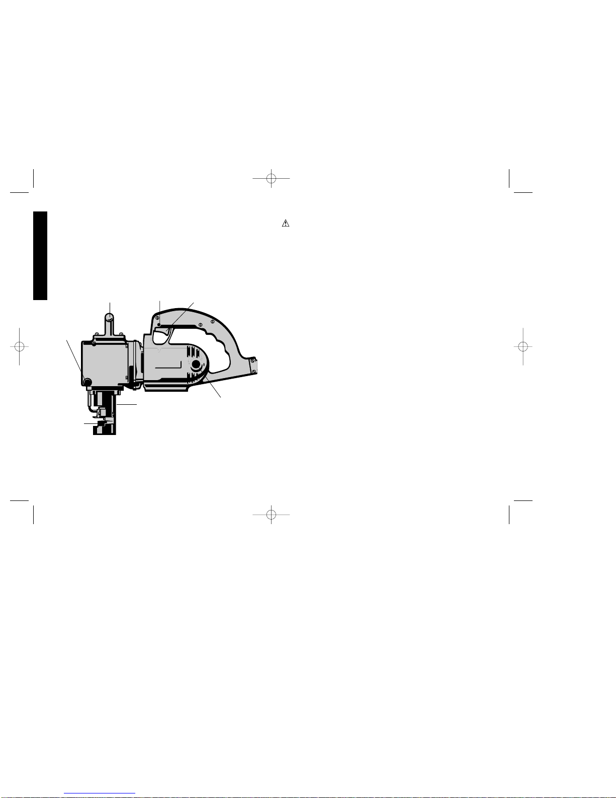
AUXILIARY
HANDLE
TRIGGER
SWITCH
SHOE
DIE
OIL FLOW
CONTROL
KNOB
LOCK
BUTTON
BRUSH INSPECTION
CAP (2)
DW899/384346 IM 5/2/02 1:44 PM Page 4
Page 4

• SECURE WORK. Use clamps or a vise to hold work. It’s safer than
using your hand and it frees both hands to operate tool.
• DON’T OVERREACH. Keep proper footing and balance at all
times.
• MAINTAIN TOOLS WITH CARE. Keep tools sharp and clean for
better and safer performance. Follow instructions for lubricating
and changing accessories. Inspect tool cords periodically and if
damaged, have repaired by authorized service facility. Inspect
extension cords periodically and replace if damaged. Keep
handles dry, clean, and free from oil and grease.
• DISCONNECT OR LOCK OFF TOOLS when not in use, before
servicing, and when changing accessories, such as blades, bits,
cutters.
• REMOVE ADJUSTING KEYS AND WRENCHES. Form habit of
checking to see that keys and adjusting wrenches are removed
from tool before turning it on.
• AVOID UNINTENTIONAL STARTING. Don’t carry tool with finger
on switch. Be sure switch is off when plugging in.
• EXTENSION CORDS. Use only 3-wire extension cords that have
3-prong grounding-type plugs and 3-pole receptacles that accept
the tool’s plug. Replace or repair damaged cords. Make sure your
extension cord is in good condition.
Minimum Gage for Cord Sets
Volts Total Length of Cord in Feet
120V 0-25 26-50 51-100 101-150
240V 0-50 51-100 101-200 201-300
Ampere Rating
More Not more AWG
Than Than
0-6 18161614
6 - 10 18 16 14 12
10-1216161412
12 - 16 14 12 Not Recommended
When using an extension cord, be sure to use one heavy enough
to carry the current your product will draw. An undersized cord will
cause a drop in line voltage resulting in loss of power and
overheating. The following table shows the correct size to use
depending on cord length and nameplate ampere rating. If in
doubt, use the next heavier gage. The smaller the gage number,
the heavier the cord.
• OUTDOOR USE EXTENSION CORDS. When tool is used
outdoors, use only extension cords intended for use outdoors and
so marked.
• STAY ALERT. Watch what you are doing. Use common sense.
Do not operate tool when you are tired.
• CHECK DAMAGED PARTS. Before further use of the tool, a
guard or other part that is damaged should be carefully checked
to determine that it will operate properly and perform its intended
function. Check for alignment of moving parts, binding of moving
parts, breakage of parts, mounting, and any other conditions that
may affect its operation. A guard or other part that is damaged
should be properly repaired or replaced by an authorized service
center unless otherwise indicated elsewhere in this instruction
manual. Have defective switches replaced by authorized service
center. Do not use tool if switch does not turn it on and off.
Grounding Instructions
This tool should be grounded while in use to protect the operator from
electric shock. The tool is equipped with a 3-conductor cord and 3prong grounding type plug to fit the proper grounding type receptacle.
The green (or green and yellow) conductor in the cord is the
grounding wire. Never connect the green (or green and yellow) wire
to a live terminal. If your unit is intended for use on less than 150 V,
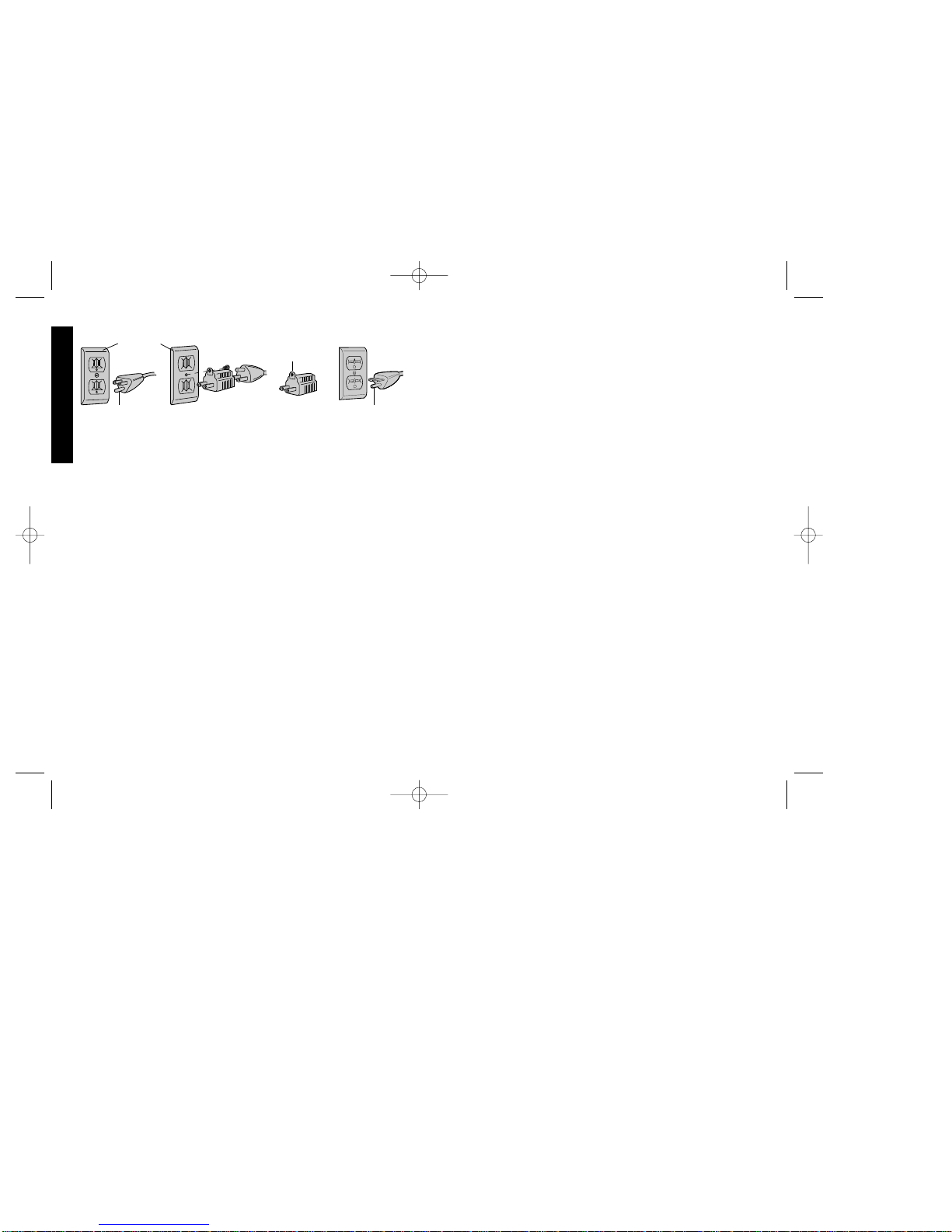
it has a plug that looks like that shown in sketch A. If it is for use on
150 to 250 V, it has a plug that looks like that shown in sketch D. An
adapter, sketches B and C, is available for connecting sketch A type
plugs to 2-prong receptacles. The green-colored rigid ear, lug, or the
like, extending from the adapter must be connected to a permanent
ground, such as a properly grounded outlet box. No adapter is
available for a plug as shown in sketch D. ADAPTER SHOWN IN
FIGURES B and C IS NOT FOR USE IN CANADA.
1
English
DW899/384346 IM 5/2/02 1:44 PM Page 1
Page 5
2
SAVE THESE INSTRUCTIONS
Motor
Your DEWalt tool is powered by a DEWalt-built motor. Be sure your power
supply agrees with the nameplate marking.
Volts 50/60 Hz or “AC only” means your tool must be operated on
alternating current and never with direct current.
Voltage decrease of more than 10% will cause loss of power and
overheating. D
EWalt tools are factory tested; if this tool does not operate,
check power supply.
Switch
Depress the trigger switch to turn the tool on. Releasing the trigger
turns the tool off. To lock the trigger in the on position for continuous
operation, depress the trigger, push in the lock button on the left
side of the handle, and then release the trigger. To release the
locking mechanism, depress trigger fully, then release it.
Operation
The nibbler will cut U.S. standard 8-gauge mild steel and 3/16" nonferrous metals. It will also cut U.S. standard 10-gauge stainless steel
easily; however, due to hardness variations in stainless steel, it is best
to first consult your local D
EWAL T field representative about such jobs
in order to obtain maximum life and efficiency from your tool.
1. Always be sure that area to be cut is oiled. An oiler device is
located at the front of the tool, and will automatically oil the area to
English
be cut. Lubricant flow is controlled by turning the knurled knob
(Figure 1).
To refill automatic oiler, remove oil filler plug (Figure 1). Be sure vent
hole in plug is kept open to ensure poper flow. For cutting mild
steel, use SAE 20W oil; for non-ferrous metals, use light oil.
2. Properly adjust stripper.
a. Loosen the 2 stripper mounting screws (Figure 1).
b. Place metal to be cut between die and stripper.
c. Lock stripper into position so that the metal is flat against the
die, and the ball of the oiler in the stripper is just touching the
metal. Average clearance of .010"-.015" is preferred. If punch is
dulled, more clearance may be required to clear the resulting
burr.
d. Be sure stripper mounting screws are tightened securely .
3. Grasp the tool, turn switch on and feed tool into material. Hold tool
so that it feeds with minimum operator pressure.
NOTE: Hard materials will dull the punches and dies. When dulling
occurs, tool will become difficult to feed into material. In addition,
the metal will begin to show burrs along the cut. Keep dies and
punches sharp at all times.
Removing Punch
1. Operate the crank down mechanism (with a screwdriver) to align
the punch retaining set screw with the clearance hole at the rear of
the shoe.
2. Loosen punch retaining set screw until punch slides free.
3. Remove die by taking out the 2 die screws located at an angle at
the bottom rear of the shoe.
4. Remove the 2 stripper mounting screws. If there is any side play
or forward play, replace stripper or it will cause severe wear and
damage to the shoe.
5. Slide punch and stripper out of shoe.
AB CD
GROUNDING PIN
GROUNDED
OUTLET
BOX
GROUNDING
MEANS
GROUNDING PIN
ADAPTER
DW899/384346 IM 5/2/02 1:44 PM Page 2
Page 6
6. Replace punch and reassemble tool by reversing steps 2-5
above.
BE SURE TO THOROUGHLY CLEAN AND LIGHTLY OIL ALL
LOCATING SURFACES BEFORE REASSEMBLY TO PREVENT
DAMAGE TO TOOL. ALSO MAKE CERT AIN THAT STRIPPER IS
SECURELY LOCKED IN POSITION AND PUNCH IS PROPERLY
SEATED BEFORE FINALLY TIGHTENING THE PUNCH
RETAINING SET SCREW.
Removing Die
1. Remove 2 die screws located an an angle at bottom rear of shoe
and remove die (Figure 1).
2. If sharpening of die is required, sharpen on a surface grinder by
removing material from only the top surface of the die. Grinding by
a qualified machine shop is preferred. CAUTION: Remember
that the total amount of metal removed from both the punch and
the die cannot exceed 3/32".
3. Clean die and shoe surface thoroughly.
4. Insert die in tool.
5. Replace screws and tighten securely.
Maintenance
Nibblers should be cleaned, inspected, and lubricated at certified
D
EWAL T service centers every month with heavy usage, every two or
three months with light usage.
Inspect carbon motor brushes frequently by unplugging tool,
removing the brush inspection caps, and withdrawing the brush and
spring assembly. Replace the assembly when the brushes are worn
down to the line closest to the spring, or when spring exerts
insufficient pressure to hold brush against commutator. Keep brushes
clean and sliding freely in their guides.
Saturate the felt oiler with SAE 10W or 20W motor oil once very day
of operation in normal use.
3
English
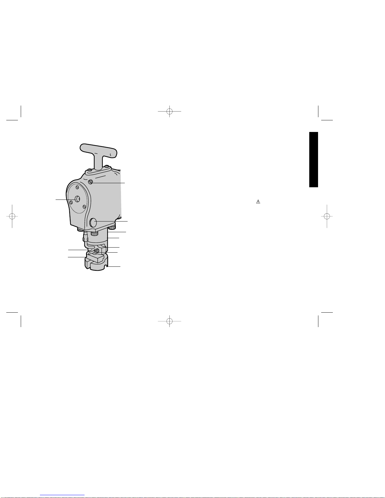
FIG. 1
CRANK DOWN
SLOT
OIL FILLER
PLUG
OIL FLOW
CONTROL KNOB
STRIPPER
SHOE
STRIPPER MOUNTING
SCREWS (2)
DIE
DIE SCREWS (2)
CLEARANCE HOLE
FELT OILER
DW899/384346 IM 5/2/02 1:44 PM Page 3
Page 7

4
Accessories
Recommended accessories for use with your tool are available at
extra cost from your distributor or local service center.
CAUTION: The use of any non-recommended accessory may be
hazardous.
Important
To assure product SAFETY and RELIABILITY, repairs, maintenance
and adjustment (including brush inspection and replacement) should
be performed by authorized service centers or other qualified service
organizations, always using identical replacement parts.
Full Warranty
DEWALT heavy duty industrial tools are warranted for one year from
date of purchase. We will repair, without charge, any defects due to
faulty materials or workmanship. For warranty repair information,
call 1-800-4-D
EWAL T. This warranty does not apply to accessories or
damage caused where repairs have been made or attempted by
others. This warranty gives you specific legal rights and you may
have other rights which vary in certain states or provinces.
In addition to the warranty, D
EWALT tools are covered by our:
30 DAY NO RISK SATISFACTION GUARANTEE
If you are not completely satisfied with the performance of your
D
EWALTheavy duty industrial tool, simply return it to the participating
seller within 30 days for a full refund. Please return the complete unit,
transportation prepaid. Proof of purchase may be required.
English
DW899/384346 IM 5/2/02 1:44 PM Page 4
Page 8

IMPORTANTES MESURES DE
SÉCURITÉ (POUR TOUS LES
OUTILS)
AVERTISSEMENT : Afin de réduire les risques d’incendie, de
secousses électriques ou de blessures lorsqu’on utilise des outils
électriques, il faut toujours respecter les mesures de sécurité
suivantes.
LIRE TOUTES LES DIRECTIVES.
.
Importantes mesures de sécurité
• S’ASSURER QUE LES PROTECTEURS sont en place et en bon
état.
• BIEN DÉGAGER LA SURFACE DE TRAVAIL. Des surfaces et
des établis encombrés peuvent être la cause de blessures.
• TENIR COMPTE DU MILIEU DE TRAVAIL. Protéger les outils
électriques de la pluie. Ne pas s’en servir dans des endroits
humides ou mouillés. Bien éclairer la surface de travail.
• ÉLOIGNER LES ENFANTS. Tous les visiteurs doivent être tenus
à l’écart de l’aire de travail.
• RENDRE L’ATELIER SÛR POUR LES ENFANTS à l’aide de
cadenas, de disjoncteurs, ou en retirant les clés de mise en
tension.
• NE JAMAIS FORCER L’OUTIL. Afin d’obtenir un rendement sûr
et efficace, utiliser l’outil à son rendement nominal.
• UTILISER L’OUTIL APPROPRIÉ. Ne jamais exiger d’un petit outil
ou d’un accessoire le rendement d’un outil de fabrication plus
robuste.
• UTILISER DES CORDONS DE RALLONGE APPROPRIÉS.
S’assurer que le cordon de rallonge est en bon état. Lorsqu’on se
sert d’un cordon de rallonge, s’assurer qu’il est de calibre approprié
pour la tension nécessaire au fonctionnement de l’outil. L’utilisation
d’un cordon de calibre inférieur occasionne une baisse de tension
5
Français
POUR TOUT RENSEIGNEMENT SUPPLÉMENTAIRE SUR CET
OUTIL OU TOUT AUTRE OUTIL D
EWALT, COMPOSER SANS
FRAIS LE NUMÉRO:
1 800 4-DEWALT (1 800 433-9258)
POIGNÉE
AUXILIARE
INTERRUPTEUR
MATRICE
POINÇON
BOUTON
À REGLER
HUILE
BOUTON
DETENTE
CAPSULE DU
INSPECTION
DW899/384346 IM 5/2/02 1:44 PM Page 5
Page 9

6
entraînant une perte de puissance et la surchauffe. Le tableau
suivant indique le calibre approprié selon la longueur du cordon et
les mentions de la plaque signalétique de l’outil. En cas de doute,
utiliser un cordon de calibre supérieur. Le chiffre indiquant le
calibre est inversement proportionnel au calibre du cordon.
• CORDONS DE RALLONGE POUR L’EXTÉRIEUR. Lorsque l’outil
sert à l’extérieur, utiliser seulement des cordons de rallonge prévus
à cet effet et portant la mention appropriée.
Calibre minimal des cordons de rallonge
Tension Longueur totale du cordon en pieds
120 V 0-25 26-50 51-100 101-150
240 V 0-50 51-100 101-200 201-300
Intensité (A)
Au Au Calibre moyen de fil (AWG)
moins plus
0-6 18161614
6 - 10 18 16 14 12
10-1216161412
12 - 16 14 12 Non recommandé
• PORTER DES VÊTEMENTS APPROPRIÉS. Éviter de porter des
vêtements amples, des gants, des cravates, des bagues, des
bracelets ou d’autres bijoux qui peuvent être happés par les pièces
en mouvement. Le port des chaussures à semelle antidérapante
est recommandé. Protéger la chevelure si elle est longue.
• TOUJOURS PORTER DES LUNETTES DE SÉCURITÉ. Porter
également un masque respiratoire si le travail de coupe produit de
la poussière. Des lunettes de correction de la vue standard
comportent seulement des verres résistant aux chocs; ce NE sont
PAS des lunettes de sécurité.
• NE PAS DÉPASSER SA PORTÉE. Toujours demeurer dans une
position stable et garder son équilibre.
• PRENDRE SOIN DES OUTILS. Conserver les outils propres et
affûtés pour qu’ils donnent un rendement supérieur et sûr. Suivre
les directives relatives à la remplacement des accessoires.
• DÉBRANCHER L’OUTIL avant de le réparer ou d’en changer un
accessoire (comme une lame, un foret ou un couteau).
• MINIMISER LES RISQUES DE DÉMARRAGES ACCIDENTELS.
S’assurer que l’interrupteur est en position hors tension avant de
brancher l’outil.
• UTILISER LES ACCESSOIRES RECOMMANDÉS. Consulter le
guide d’utilisation afin de connaître les accessoires recommandés.
L’utilisation d’accessoires inappropriés présente des risques de
blessures.
• NE JAMAIS SE TENIR SUR L’OUTIL. Cela présente des risques
de blessures graves si l’outil bascule ou si on touche à la lame par
inadvertance.
• VÉRIFIER LES PIÈCES ENDOMMAGÉES. Avant de continuer à
utiliser l’outil, il faut vérifier si le protecteur ou toute autre pièce
endommagée remplit bien la fonction pour laquelle il a été prévu.
Vérifier l’alignement et les attaches des pièces mobiles, le degré
d’usure des pièces et leur montage, ainsi que tout autre facteur
susceptible de nuire au bon fonctionnement de l’outil. Il faut réparer
ou remplacer tout protecteur ou autre composant endommagé.
• NE JAMAIS LAISSER UN OUTIL EN MARCHE SANS
SURVEILLANCE. LE METTRE HORS TENSION. Ne pas laisser
l’outil avant l’immobilisation complète de la lame.
Mise à la terre
En cas de mauvais fonctionnement ou de bris de l’outil, la mise à la
terre procure un chemin de moindre résistance au courant électrique
afin de minimiser les risques de secousses électriques. Le cordon de
l’outil comporte un conducteur de terre et une fiche de mise à la terre.
La fiche doit être branchée dans une prise de machine bien installée
et mise à la terre conformément aux lois et règlements locaux. Ne
pas modifier la fiche fournie. Lorsque la fiche n’entre pas dans la
prise, demander à un électricien qualifié d’installer une prise
appropriée.
La mauvaise connexion du conducteur de terre de l’outil présente
des risques de secousses électriques. Le conducteur dont l’isolant
est vert ou vert avec des lignes jaunes constitue la mise à la terre. En
cas de réparation ou de remplacement du cordon ou de la fiche, ne
pas relier le conducteur de terre à une borne sous tension.
Français
DW899/384346 IM 5/2/02 1:44 PM Page 6
Page 10

Consulter un électricien qualifié ou le personnel des centres de
service an cas d’incompréhension des instructions relatives à la mise
à la terre ou en cas de doute quant à la mise à la terre de l’outil.
Utiliser seulement des cordons de rallonge trifilaires dotés de fiche
mise à la terre à trois broches, ainsi que des prises à 3 orifices
acceptant la fiche de l’outil.
Réparer ou remplacer immédiatement les cordons endommagés ou
usés.
L ‘outil est conçu pour être branché sur un circuit dont les prises
ressemblent à celle illustrée à la figure A. L’outil comporte une fiche
de terre qui ressemble à celle illustrée à la figure A. On peut se servir
d’un adaptateur temporaire (comme celui des figures B et C) pour
brancher la fiche dans une prise à 2 orifices (fig. B) lorsqu’il n’y a
pas de prise mise à la terre. Il faut seulement se servir de
l’adaptateur temporaire jusqu’à ce qu’un électricien certifié puisse
installer une prise mise à la terre appropriée. Il faut alors relier l’oreille
rigide, la cosse ou tout autre objet du genre de couleur verte à une
mise à la terre permanente (comme à la boîte d’une prise bien mise
à la terre)
Moteur
Un moteur DEWALT actionne l'outil DEWALT. Veiller à ce que la
tension d'alimentation soit conforme aux exigences de la plaque
signalétique de l'outil.
La mention «Volts 50-60 Hz» ou «c.a. seulement» signifie que l'outil
fonctionne sur du courant alternatif et jamais sur de courant continu.
Une baisse de tension de plus de 10 p. 100 entraîne une perte de
puissance et la surchauffe. Tous les outils DEWALT sont essayés
avant de quitter l'usine. Lorsque celui-ci refuse de fonctionner,
vérifier la source de courant électrique.
Interrupteur
Enfoncer l'interrupteur à détente pour mettre l'outil en marche. Pour
l'arrêter, relâcher la détente. Pour verrouiller la détente en mode de
fonctionnement continu, enfoncer la détente, pousser le bouton de
verrouillage qui se trouve du côté gauche de la poignée, puis
relâcher la détente. Pour dégager le mécanisme de verrouillage,
enfoncer à fond la détente et la relâcher immédiatement.
Fonctionnement
La grignoteuse coupe de l'acier de calibre 8 US standard et des
métaux non ferreux de 5 mm (3/16 po). Elle peut couper aisément
de l'acier de calibre 10 US standard mais, en raison de différentes
duretés de l'acier inoxydable, il vaut mieux consulter au préalable
son représentant DEWALT afin d'optimiser la durée et l'efficacité de
l'outil.
1. Toujours s'assurer que la surface à couper est huilée. Il y a un
graisseur à l'avant de l'outil qui huile automatiquement la surface
à couper. On contrôle le débit du lubrifiant en faisant tourner le
bouton moleté (fig. 1).
Pour remplir le graisseur automatique, retirer le bouchon de
remplissage d'huile (fig. 1). S'assurer que l'évent du bouchon est
ouvert pour procurer un débit convenable. Pour couper de l'acier
doux, utiliser de l'huile SAE 20W. Pour couper des métaux non
ferreux, utiliser de l'huile légère.
2. Bien régler le déflecteur.
a. Desserrer les deux vis de montage du déflecteur (fig. 1).
b. Placer le métal à couper entre la matrice et le déflecteur.
c. Verrouiller le déflecteur en place de sorte que le métal repose à
7
Français
AB C
BROCHE DE PRISE
MISE À LA TERRE
PRISE MISE
À LA TERRE
DISPOSITIF DE
MISE À LA TERRE
ADAPTATEUR
DW899/384346 IM 5/2/02 1:44 PM Page 7
Page 11

8
plat contre la matrice et que la bille du graisseur dans le déflecteur
effleure le métal. Il est conseillé de laisser un jeu moyen de XX
mm à XX mm (de 0,010 à 0,015 po). Lorsque le poinçon est
émoussé, il faut laisser plus de jeu afin de laisser passer les
ébarbages qui en résulte.
d. S'assurer que les vis de montage du déflecteur sont bien
serrées.
3. Saisir l'outil, actionner l'interrupteur et faire avancer l'outil dans le
matériau. Saisir l'outil de sorte que l'utilisateur y exerce une
pression minimale.
NOTE : Des matériaux durs font émousser les poinçons et les
matrices. Le cas échéant, l'outil avance difficilement dans le
matériau. En outre, le matériau commence à ébarber le long de la
ligne de coupe. S'assurer que les matrices et les poinçons sont
affûtés en tout temps.
RETRAIT DU POINÇON
1. Actionner le mécanisme d'abaissement du poinçon (à l'aide d'un
tournevis) afin d'aligner la vis de pression qui retient le poinçon
sur le trou à l'arrière du patin.
2. Desserrer la vis de pression qui retient le poinçon jusqu'à ce que
ce dernier glisse librement.
3. Retirer la matrice en enlevant les deux vis de la matrice qui se
trouvent en angle sous le patin à l'arrière.
4. Retirer les deux vis de montage du déflecteur. En cas de jeu
latéral ou avant, remettre le déflecteur en place au risque d'user
gravement le patin et de l'endommager.
5. Faire glisser le poinçon et le déflecteur hors du patin.
6. Remettre le poinçon en place et remonter l'outil en répétant les
étapes 2 à 5 précédentes dans l'ordre inverse.
BIEN NETTOYER ET HUILER LÉGÈREMENT TOUTES LES
SURFACES D'ALIGNEMENT AVANT DE REMONTER L'OUTIL
AFIN DE NE PAS L'ENDOMMAGER. S'ASSURER ÉGALEMENT
QUE LE DÉFLECTEUR EST BIEN VERROUILLÉ EN PLACE ET
QUE LE POINÇON EST BIEN INSTALLÉ A V ANT DE SERRER LA
VIS DE PRESSION QUI RETIENT LE POINÇON.
Français
FIG. 1
ENTAILLER
DU
MANIVELLE
TAMPON DE
PETROLE
REMPLIR
BOUTON DE
PETROLE
ÉCOULEMENT
DÉPOUILLER
MATRICE
VIS DÉPOUILLER
MONTAGNE (2)
POINÇON
VIS DE POINÇON (2)
ORIFICE DÉGAGEMENT
PETROLE DE TORCHON
DW899/384346 IM 5/2/02 1:44 PM Page 8
Page 12

DEWALT Industrial Tool Company
626 Hanover Pike, P.O. Box 158
Hampstead, MD. 21074-0158
É.-U.
1 (800) 4-D
EWALT (433-9258)
MISE EN GARDE : L’utilisation de tout accessoire non
recommandé peut être dangereuse.
Important
Pour assurer la SÉCURITÉ D’EMPLOI et la FIABILITÉ de l’outil, n’en
confier la réparation, l’entretien et les rajustements (y compris
l’inspection et le remplacement des balais) qu’à un centre de service
ou à un atelier d’entretien autorisé n’utilisant que des pièces de
rechange identiques.
La division des outils industriels de Black & Decker s’occupe de
l’entretien et des réparations des outils industriels D
EWALT.
Garantie complète
Les outils industriels de service intensif DeWALT sont garantis
pendant un an à partir de la date d’achat. Toute pièce d’un outil
D
EWALT qui s’avérait défectueuse en raison d’un vice de matière ou
de fabrication sera réparée sans frais. Selon une entente convenue
entre D
EWAL T et Black& Decker, la Division des outils industriels de
Black & Decker (U.S.) Inc. s’engage à effectuer les réparations
couvertes par la présente garantie. Il suffit de retourner l’outil complet
à un centre de service D
EWALT. La présente garantie ne couvre pas
les accessoires ni les avaries dues aux réparations tentées ou
effectuées par des tiers.
En outre, la garantie suivante couvre les outils D
EWALT.
GARANTIE DE SATISFACTION DE 30 JOURS OU ARGENT
REMIS
Si, pour quelque raison que ce soit, l’outil ne donne pas entière
satisfaction, il suffit de le retourner où il a été acheté dans les 30 jours
suivant la date d’achat afin d’obtenir un nouvel outil identique.
9
Français
RETRAIT DE LA MATRICE
1. Retirer les deux vis de la matrice qui se trouvent en angle sous le
patin, à l'arrière, et retirer la matrice (fig. 1).
2. Lorsqu'il faut affûter la matrice, utiliser une meule en enlevant du
matériau seulement sur la face supérieure de la matrice. Il est
conseillé d'en confier l'affûtage à un atelier spécialisé.
MISE EN GARDE : Se rappeler que la quantité totale de métal
poncé du poinçon et de la matrice ne doit pas excéder 5 mm (3/32 po).
3. Bien nettoyer la matrice et la surface du patin.
4. Installer la matrice sur l'outil.
5. Remettre les vis en place et bien les serrer.
Entretien
Il faut confier le nettoyage, l'inspection et la lubrification de la
grignoteuse au personnel d'un centre de service DEWALT autorisé à
chaque mois, lorsqu'on s'en sert de façon intensive, ou aux 2 à 3
mois, pour une utilisation normale.
Vérifier souvent les balais de carbone du moteur en débranchant
l'outil, en retirant les couvercles d'inspection des balais et en retirant
les assemblages balai-ressort. Remplacer les assemblages lorsque
les balais sont usés jusqu'à la ligne la plus près du ressort ou lorsque
le ressort n'exerce plus la pression suffisante pour retenir le balai
contre le commutateur. S'assurer que les balais sont propres et qu'ils
glissent librement dans leurs guides.
Saturer le graisseur d'huile à moteur SAE 10W ou 20W une fois par
journée d'utilisation normale.
Accessoires
Les accessoires recommandés pour l’outil sont vendus séparément
chez les détaillants et au centre de service autorisé de la région. Pour
trouver un accessoire, prière de communiquer à l’adresse suivante ou
composer le numéro suivant.
DW899/384346 IM 5/2/02 1:44 PM Page 9
Page 13

10
Instrucciones importantes de seguridad
ADVERTENCIA: Es indispensable sujetarse a las precauciones
básicas de seguridad, con la finalidad de reducir el peligro de
incendio, choque eléctrico y lesiones personales, en todas las
ocasiones en que se utilicen herramientas eléctricas. Entre estas
precauciones se incluyen las siguientes.
LEA TODAS LAS INSTRUCCIONES
Instrucciones importantes de seguridad
• CONSERVE LAS GUARDAS EN SU SITIO y listas para trabajar.
• CONSERVE LIMPIA EL AREA DE TRABAJO. Las áreas y bancos
con objetos acumulados en desorden propician los accidentes.
• NO SE EMPLEE EN AMBIENTES PELIGROSOS. No utilice
herramientas eléctricas en ligares inundados o mojados, ni las
exponga a la lluvia. Conserve bien iluminada el área de trabajo.
• CONSERVE APARTADOS A LOS NIÑOS. Todos los visitantes
deben permanencer a distancia segura de la zona de trabajo.
• HAGA SU TALLER A PRUEBA DE NIÑOS con candados,
interruptores maestros y retirando las llaves de encendido.
• NO FUERCE LA HERRAMIENTA. Esta cumplirá mejor con su
trabajo y de manera más segura bajo las especificaciones para las
que se diseñó.
• EMPLEE LA HERRAMIENTA ADECUADA. No fuerce una
herramienta o sus dispositivos en una tarea para los que no han
sido diseñados.
• UTILICE UN CABLE DE EXTENSION ADECUADO. Asegúrese
que su extensión esté en buenas condiciones. Cuando utilice una
extensión, asegúrese de emplear una que soporte la corriente que
su herramienta necesita. Una extensión con calibre insuficiente
provocará una caída en el voltaje de la línea, ocasionando pérdida
de potencia y sobrecalentamiento. El cuadro siguiente muestra el
calibre correcto a utilizarse de acuerdo con la longitud y el
amperaje indicado en la placa de identificación. Si tiene dudas,
utilice el calibrte siguiente. Mientras más pequeño sea el número
del calibre, mayor será su capacidad.
Español
Epecificaciones (DW899)
Tensión de alimentación 120 V CA/CD
Potencia nominal: 380 W
Frecuencia de operación:60 Hz
Consumo de corriente: 7,0 A
MANGO
AUXILIAR
INTERRUPTOR
DE GATILLO
ZAPATA
DADO
PERILLA DE
CONTROL DE
FLUJO DE
ACEITE
BOTON DE
ENCENDIDO
PERMANENTE
TAPA DE INSPECCION DE
CARBON (2)
DW899/384346 IM 5/2/02 1:44 PM Page 10
Page 14

Calibre mínimo para cordones de extensión
Volts Longitud total del cordón en metros
120V 0-7,6 7,6-15,2 15,2-30,4 30,4-45,7
240V 0-15,2 15,2-30,4 30,4-60,9 60,9-91,4
AMPERAJE
Más No más Calibre del cordón AWG
de de
0-6 18161614
6 - 10 18 16 14 12
10-1216161412
accesorios inadecuados puede causar riesgos de lesiones.
• NUNCA SE PARE EN LA HERRAMIENTA. Puede provocarse
lesiones graves si la herramienta se vuelca o si hace contacto
accidental con la herramienta de corte.
• REVISE LAS PARTES DAÑADAS. Antes de seguir utilizando la
herramienta, debe revisar cuidadosamente una guarda o cualquier
otra pieza que esté dañada para determinar si cumplirá
adecuadamente con su función; revise la alineación de las piezas
móviles, sus montajes, ruptura de partes y cualesquiera otras
condiciones que pudiesen afectar su operación. Repare o
reemplace las piezas dañadas.
• NUNCA DEJE LA HERRAMIENTA EN FUNCIONAMIENTO Y
DESATENDIDA. APAGUELA. No deje la herramienta hasta que
se haya detenido por completo.
• VERIFIQUE LAS PARTES DA„ADAS. Antes de seguir
empleando cualquier herramienta, es indispensable verificar con
mucho cuidado que las guardas u otras partes da–adas puedan
operar de la manera adecuada para cumplir con su funci—n.
Verifique la alineaci—n de las partes m—viles, la firmeza con que
deben encontrarse sujetas en sus montaduras, las partes rotas,
las propias montaduras y cualesquiera otros DETALLES que
pudieran afectar a la operaci—n de la herramienta. Las guardas y
las otras partes que se encuentren da–adas deber‡n repararse
bien o cambiarse en un centro de servicio autorizado, a menos
que se diga otra cosa en el manual del usuario. Haga que se
cambien los interruptores da–ados en un centro de servicio
autorizado. No emplee ninguna herramienta que tenga inutilizado
o estropeado el interruptor.
Instrucciones de conexión a tierra
En el caso de mal funcionamiento, la tierra proporciona una vía de
menor resistencia a la corriente eléctrica para reducir el riesgo de
choque eléctrico. Esta herramienta está equipada con un cable
eléctrico con un conductor a tierra y pata de aterrizaje. La clavija debe
conectarse a una toma de corriente instalada correctamente y
11
Español
12 - 16- 14 12 No recomendado
• CORDONES DE EXTENSION PARA INTEMPERIE. Cuando
utilice la herramienta a la intemperie, solamente utilice extensiones
diseñadas para ello y así marcadas.
• VISTA LAS PRENDAS ADECUADAS. No utilice prendas de
vestir flojas, guantes, corbatas, anillos, brazaletes ni otras piezas
de joyería que pudiesen quedar atrapadas en las partes móviles.
Se recomienda el empleo de calzado antiderrapante. Cúbrase el
cabello si lo tiene largo.
• SIEMPRE UTILICE GAFAS DE SEGURIDAD.También utilice una
máscara contra polvo si la operación a efectuar lo produce. Los
anteojos de uso diario solamente tienen lentes resistentes al
impacto, NO SON anteojos de seguridad.
• NO SE SOBREEXTIENDA. Conserve siempre bien apoyados los
pies, lo mismo que el equilibrio.
• CUIDE SUS HERRAMIENTAS. Conserve sus herramientas
afiladas y limpias para que funcionen mejor y de manera más
segura. Siga las instrucciones de cambio de accesorios.
• DESCONECTE LA HERRAMIENTAS antes de efectuarles
servicio y cuando les cambie acesorios, como cuchillas, brocas y
similares.
• REDUZCA EL RIESGO DE ENCENDIDO ACCIDENTAL.
Asegúrese que el interruptor esté en posición de apagado antes
de conectar la herramienta.
• UTILICE LOS ACCESORIOS RECOMENDADOS. Busque en el
manual de instrucciones los accesorios recomendados. El uso de
DW899/384346 IM 5/2/02 1:44 PM Page 11
Page 15

12
aterrizada de conformidad con todos los reglamentos locales. No
modifique la clavija, si no se ajusta a la toma de corriente, haga que
un electricista calificado le instale una toma adecuada.
La conexión incorrecta del conductor a tierra del equipo puede
originar riesgos de choque eléctrico. El conductor cuyo aislamiento es
de color verde con o sin franjas amarillas es el conductor a tierra del
equipo. Si se requiere reparación o cambio del cable eléctrico o la
clavija, no conecte el conductor a tierra a una terminal viva.
Consulte con un electricista si no comprende perfectamente las
instrucciones de aterrizaje, o si tiene dudas acerca de la conexión a
tierra de su equipo.
Utilice solamente extensiones de tres cables que tengan clavijas de
tres patas y tomas de corriente de tres polos que acepten la clavija de
la herramienta.
Repare o reemplace inmediatamente los cables dañados o
desgastados.
Esta herramienta está diseñada para utilizarse en circuitos que
tengan una toma de corriente similar a la ilustrada en la figura A. Se
puede utilizar un adaptador temporal, que se parece al mostrado en
las figuras B y C, para conectar esta clavija a una toma de corriente
de dos polos como se observa en la figura B si no dispone de una
toma aterrizada. Solamente debe utilizar el adaptador temporal hasta
que un electricista le instale una toma apropiada.
La oreja, lengüeta, o similar de color verde que se extiende del
adaptador debe conectarse a tierra permanente, como una toma de
corriente aterrizada.
CONSERVE ESTAS
INSTRUCCIONES
Motor
Su herramienta DEWalt funciona con un motor DeWalt integrado.
Asegúrese que la alimentación de corriente concuerde con la
señalada en la placa de identificación.
Volts 50/60 hz o “ac only” significa que su herramienta debe operarse
con corriente alterna y nunca con corriente directa.
Disminuciones en el voltaje mayores a 10% causarán pérdida de
potencia y sobrecalentamiento. Las herramientas DEWalt se
prueban en la fábrica; si esta herramienta no funciona, revise la
alimentación de corriente.
Interruptor
Oprima el interruptor de gatillo para encender la cizalla, suéltelo para
apagarla. El interruptor se puede asegurar en posición de encendido
activando el botón de encendido permanente que se encuentra del
lado izquierdo del mango, al mismo tiempo que se conserva el
interruptor oprimido. Asegúrese siempre que la herramienta no tenga
activado el mecanismo de encendido permanente antes de
conectarla. Para apagar la unidad cuando este mecanismo está
activado, oprima y libere el interruptor una vez.
Español
AB C
PATA DE
CONEXION A
TIERRA
TOMA DE
CORRIENTE
ATERRIZADA
MEDIO DE
ATERRIZAJE
ADAPTADOR
DW899/384346 IM 5/2/02 1:44 PM Page 12
Page 16

Operación
La cortadora cortará lámina de acero blando calibre 8 estándar U.S.
y metales no ferrosos de 4,7 mm (3/16”) de espesor. También cortará
lámina de acero inoxidable calibre 10 estándar U.S.; sin embargo,
debido a las variaciones de dureza en el acero inoxidable, es mejor
que consulte primero con el representante de campo de DeWALT
de su localidad acerca de dichos trabajos para obtener la máxima
durabilidad y utilidad de su herramienta.
1. Asegúrese siempre que el área que vaya a cortar esté aceitado.
La herramienta cuenta en el frente con un dispositivo para aceitar,
y automáticamente aceitará la zona de corte. El flujo del
lubricante se controla girando la perilla moleteada (figura 1).
Para rellenar la aceitera automática, retire el tapón (figura 1).
Asegúrese que el orificio de ventilación del tapón se conserve
abierto para garantizar el flujo apropiado. Para cortar acero
blando, utilice aceite SAE 20W; para metales no ferrosos utilice
aceite ligero.
2. Ajuste el separador adecuadamente.
a. Afloje los 2 tornillos de montaje del separador (figura 1).
b. Coloque el metal a cortar entre el troquel y el separador.
c. Asegure en posición el separador de manera que el metal quede
plano contra el troquel, y el balín de la aceitera apenas haga
contacto con el material. Es preferible dejar una luz promedio de
entre 0,25 mm y 0,38 mm (0,010” - 0,015”). Si el punzón no tiene
mucho filo, se requerirá mayor luz para librar la rebaba resultante.
d. Asegúrese que los tornillos de montaje del separador queden bien
apretados.
3. Sujete la herramienta, encienda el interruptor y aliméntela en el
materia. Sujete la herramienta de manera que esta avance con
mínima presión por parte del operador.
NOTA: los metales duros desafilarán los punzones y los troqueles.
Cuando esto ocurra, será difícil avanzar la herramienta en el
13
Español
FIG. 1
RANURA DEL
CIGÜEÑAL
TAPON DE LA
ACEITERA
PERILLA DE
CONTROL DE
FLUJO DE ACEITE
SEPARADOR
ZAPATA
TORNILLOS DE
MONYAJE DEL
SEPARADOR (2)
TROQUEL
TORNILLOS DEL
TROQUEL (2)
ORIFICIO DE LUZ
ACEITERA DE FIELTRO
DW899/384346 IM 5/2/02 1:44 PM Page 13
Page 17

14
3. Limpie el troquel y la superficie de la zapata perfectamente.
4. Inserte el troquel en la herramienta.
5. Coloque de nuevo los tornillos y apriete con firmeza.
Mantenimiento
La cortadora deberá ser limpiada, inspeccionada y lubricada en un
centro de servicio certificado DEWALT cada mes, si se utiliza en
tareas pesadas, y cada dos a tres meses con uso ligero.
Revise con frecuencia los carbones del motor de la siguiente
manera: desconecte la herramienta, retire las tapas de inspección de
los carbones y saque los montajes de los carbones y sus resortes.
Reemplace estos montajes cuando los carbones se hayan
desgastado hasta la línea más cercana al resorte, o cuando el
resorte haga presión insuficiente para sujetar al carbón contra el
conmutador. Conserve los carbones limpios y deslizándose
libremente en sus guías.
Sature la aceitera de fieltro con aceite SAE 10 W o 20W una vez al
día de uso normal.
Accesorios
Los accesorios recomendados para emplearse con su herramienta
están a su disposición con costo extra con su distribuidor o en el
centro de servicio de su localidad.
PRECAUCION: El uso de cualquier accesorio no recomendado para
emplearse con su herramienta puede ser peligroso.
Importante
Para garantizar la SEGURIDAD y la CONFIABILIDAD, deberán
hacerse reparaciones, mantenimiento y ajustes de esta herramienta
en los centros certificados de servicio u otras organizaciones
autorizadas que empleen siempre refacciones legítimas DEWALT.
Español
material; además el metal empezará a mostrar rebabas a lo largo del
corte. Conserve sus punzones y troqueles siempre afilados.
PARA QUITAR EL PUNZON
1. Opere el mecanismo del cigüeñal (con un destornillador) para
alinear el prisionero de retención del punzón con el orificio de luz
que se encuentra en la parte posterior de la zapata.
2. Afloje el prisionero de retención del punzón hasta que éste se
deslice hacia fuera.
3. Retire el troquel sacando los dos tornillos localizados en ángulo
en la parte inferior trasera de la zapata.
4. Quite los 2 tornillos de montaje del separador. Si hay juego lateral
o hacia delante, reemplace el separador, de otra manera causará
desgaste severo y daños a la zapata.
5. Deslice el punzón y el troquel hacia fuera de la zapata.
6. Reinstale el punzón y arme de nuevo la herramienta invirtiendo
los pasos del 2 al 5.
ASEGURESE DE LIMPIAR PERFECTAMENTE Y ACEITAR
LIGERAMENTE TODAS LAS SUPERFICIES ANTES DE RE
ENSAMBLAR PARA EVITAR DAÑOS A LA HERRAMIENTA.
ASEGURESE TAMBIEN QUE EL SEPARADOR ESTE ASEGURADO EN SU POSICION Y EL PUNZON ESTE CORRECTAMENTE ASENTADO ANTES DE APRETAR FINALMENTE
EL PRISIONERO.
REMOCION DEL TROQUEL
1. Quite los dos tornillos del troquel que se localizan en ángulo en la
parte inferior trasera de la zapata y retire el troquel (figura 1).
2. Si se requiere afilar el troquel, afílelo en un esmeril de superficie
removiendo material únicamente de la superficie superior del
troquel. Es preferible llevar a cabo este procedimiento en el
esmeril de una taller calificado. PRECAUCION: Recuerde que la
cantidad total de material removido del punzón y del troquel no
debe exceder 2,38 mm (3/32”).
DW899/384346 IM 5/2/02 1:44 PM Page 14
Page 18

Garantía Completa
Las herramientas industriales DEWALT están garantizadas durante
un año a partir de la fecha de compra. Repararemos, sin cargos,
cualquier falla debida a material o mano de obra defectuosos. Hemos
hecho arreglos con la División de Herramientas Industriales de Black
& Decker para que hagan las reparaciones en garantía a las
herramientas D
EWALT. Por favor regrese la unidad completa, con el
transporte pagado, a cualquier Centro de Servicio para Herramientas
Industriales de Black & Decker o a las estaciones de servicio
autorizado enlistadas bajo “Herramientas Eléctricas” en la Sección
Amarilla. Esta garantía no se aplica a los accesorios ni a daños
causados por reparaciones efectuadas por terceras personas. Esta
garantía le otorga derechos legales específicos, y usted puede tener
otros derechos que pueden variar de estado a estado.
En adición a la garantía, las herramientas D
EWALTestán amparadas
por nuestra:
GARANTIA DE SATISFACCION SIN RIESGO POR 30 DIAS
Si usted no se encuentra completamente satisfecho con el
desempeño de su herramienta industrial DEWALT, sencillamente
devuélvala a los vendedores participantes durante los primeros 30
días después de la fecha de compra para que le efectúen un
reembolso completo. Por favor regrese la unidad completa, con el
transporte pagado. Se puede requerir prueba de compra.
15
Español
PARA REPARACION Y SERVICIO DE SUS HERRAMIENTAS
ELECTRICAS FAVOR DE DIRIGIRSE AL CENTRO DE SERVICIO MAS
CERCANO
CULIACAN
Av. Nicolas Bravo #1063 Sur (91 671) 242 10
GAUDALAJARA
Av. La Paz #1770 (91 3) 826 69 78.
LEON
Polara #32 (91 471) 314 56
MEXICO
Sonora #134 Hiprodromo Condesa 553-9979
MERIDA
Calle 63 #459 (91 99) 23 54 90
MONTERREY
Av. Francisco I. Madero Pte. 1820-A (91 83) 72 11 25
PUEBLA
17 Norte #2057 (91 22) 46 90 20
QUERETARO
Av. Madero 139 Pte. (91 42) 14 60 60
SAN LOUIS POTOSI
Pedro Moreno #408 Fracc. la Victoria (91 48) 14 25 67
TORREON
Blvd. Independencia, 96 pte. (91 17) 16 52 65
VERACRUZ
Prolongación Diaz Miron #4280 (91 29) 21 70 18
VILLAHERMOSA
Zaragoza #105 (91 93) 12 53 17
PARA OTRAS LOCALIDADES LLAME AL: 326 7100
SECCI N
AMARILLA
Si funciona…
y funciona muy bien.
Para servicio y vientas consulte
“HERRAMIENTAS ELECTRICAS”
en la sección amarilla.
IMPORTADOR: BLACK & DECKER S.A. DE
C.V.
BOSQUES DE RADIATAS NO. 42
BOSQUES DE LAS LOMAS, 05120 MEXICO,
DW899/384346 IM 5/2/02 1:44 PM Page 15
 Loading...