

Page 1

INSTRUCTION MANUAL
GUIDE D'UTILISATION
MANUAL DE INSTRUCCIONES
DW897/DW897-220
16 Gauge Nibbler
Grignoteuse de calibre 16
Cortadora de lamina calibre 16
INSTRUCTIVO DE OPERACION, CENTROS DE SERVIClO Y POLIZA
DE GARANTiA. ADVERTENClA: LEASE ESTE INSTRUCTIVO ANTES
DE USAR EL PRODUCTO.
®
Page 2

IF YOU HAVE ANY QUESTIONS OR COMMENTS ABOUT THIS
OR ANY DEWALT TOOL, CALL US TOLL FREE AT:
1-800-4-DEWALT (1-800-433-9258)
HEAD
\
i SWITCHLOCK
PADDLESWITCH BUTTON
PUNCH--
I
SHOE
--PUNCH
GUIDE
DW897/DW897-22016-Gauge
ProfileNibbler
IMPORTANT SAFETY
INSTRUCTIONS (FOR ALL TOOLS)
z_ WARNING: When using electric tools, basic safety precautions
should always be followed to reduce risk of fire, electric shock, and
personal injury, including the following:
READ ALL INSTRUCTIONS
Double Insulation
Double insulated tools are constructed throughout with two separate
layers of electrical insulation or one double thickness of insulation
between you and the tool's electrical system. Tools built with this
insulation system are not intended to be grounded. As a result, your
tool is equipped with a two prong plug which permits you to use
extension cords without concern for maintaining a ground
connection.
NOTE: Double insulation does not take the place of normal safety
precautions when operating this tool. The insulation system is for
added protection against injury resulting from a possible electrical
insulation failure within the tool.
z_ CAUTION: WHEN SERVICING USE ONLY IDENTICAL RE-
PLACEMENT PARTS. Repair or replace damaged cords.
Polarized Plugs(DW897)
Polarized plugs (one blade is wider than the other) are used on
equipment to reduce the risk of electric shock. When provided, this
plug will fit into a polarized outlet only one way. If the plug does not
fit fully into the outlet, reverse the plug. If it still does not fit, contact a
qualified electrician to install the proper outlet. Do not change the
plug in any way.
Page 3

For All Tools:
• KEEP WORK AREA CLEAN. Cluttered areas and benches invite
injuries.
• CONSIDER WORK AREA ENVIRONMENT. Don't expose power
tools to rain. Don't use power tools in damp or wet locations. Keep
work area well lit.
• GUARD AGAINST ELECTRIC SHOCK. Prevent body contact
with grounded surfaces; for example, pipes, radiators, ranges,
and refrigerator enclosures.
• KEEP CHILDREN AWAY. All visitors should be kept away from
work area. Do not let visitors contact tool or extension cord.
• STORE IDLE TOOLS. When not in use, tools should be stored in
dry, and high or locked-up place -- out of reach of children.
• DON'T FORCE A TOOL. It will do the job better and safer at the
rate for which it was intended.
• USE RIGHT TOOL. Don't force small tool or attachment to do the
job of a heavy duty tool Don't use tool for purpose not intended; for
example, don't use circular saw for cutting tree limbs or logs.
• DRESS PROPERLY. Do not wear loose clothing or jewelry. They
can be caught in moving parts. Rubber gloves and non-skid
footwear are recommended when working outdoors. Wear
protective hair covering to contain long hair.
• USE SAFETY GLASSES. Also use face or dustmask if operation
is dusty
• DON'T ABUSE CORD. Never carry tool by cord or yank it to
disconnect from receptacle. Keep cord from heat, oil, and sharp
edges.
• SECURE WORK. Use clamps or a vise to hold work. It's safer than
using your hand and it frees both hands to operate tool
• DON'T OVERREACH. Keep proper footing and balance at all
times.
• MAINTAIN TOOLS WITH CARE. Keep tools sharp and clean for
better and safe performance. Follow instructions for lubricating and
changing accessories. Inspect tool cords periodically and if
damaged have repaired by authorized service facility. Inspect
extension cords periodically and replace if damaged. Keep
handles dry, clean, and free from oil and grease.
DISCONNECT OR LOCK OFF TOOLS when not in use, before
servicing, and when changing accessories, such as blades, bits,
cutters.
REMOVE ADJUSTING KEYS AND WRENCHES. Form habit of
checking to see that keys and adjusting wrenches are removed
from tool before turning it on.
AVOID UNINTENTIONAL STARTING. Don't carry plugged-in tool
with finger on the switch. Be sure the switch is off when plugging
in.
EXTENSION CORDS. Make sure your extension cord is in good
condition. When using an extension cord, be sure to use one
heavy enough to carry the current your product will draw. An
undersized cord will cause a drop in line voltage resulting in loss
of power and overheating. The following table shows the correct
size to use depending on cord length and nameplate ampere
rating. If in doubt, use the next heavier gage. The smaller the gage
number, the heavier the cord.
Volts
120V
240V
Ampere Rating
More Not more
Than Than
0 6
6 10
10 12
12 16
MinimumGage for Cord Sets
Total Length of Cord in Feet
0-25 26-50 51-100 101-150
0-50 51-100 101-200 201-300
AWG
18 16 16 14
18 16 14 12
16 16 14 12
14 12 Not Recommended
STAY ALERT. Watch what you are doing. Use common sense.
Do not operate tool when you are tired.
OUTDOOR USE EXTENSION CORDS. When tool is used
outdoors, use only extension cords intended for use outdoors and
so marked.
Page 4
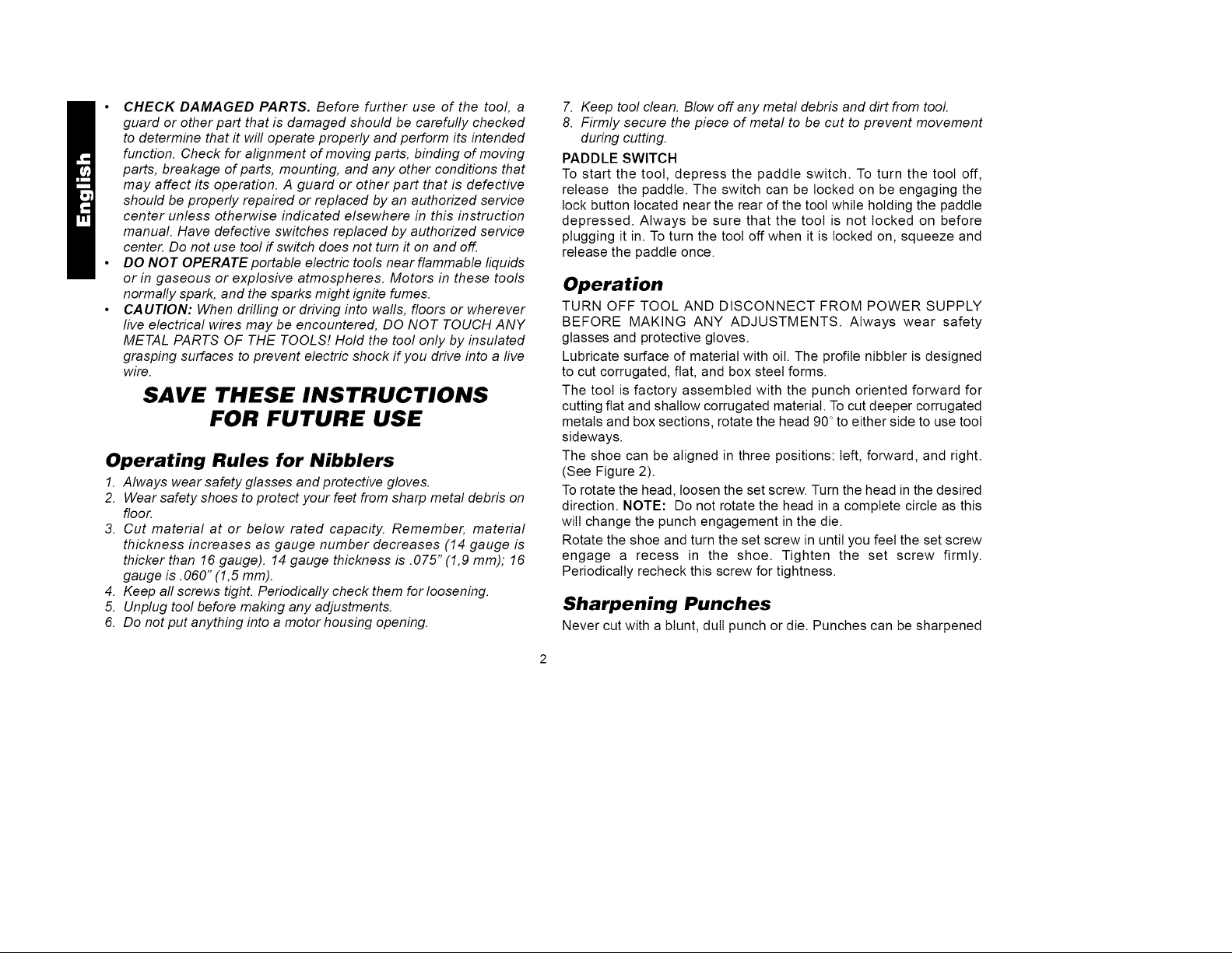
• CHECKDAMAGEDPARTS.Beforefurtheruseofthetool,a
guardor other part that is damaged should be carefully checked
to determine that it will operate properly and perform its intended
function. Check for alignment of moving parts, binding of moving
parts, breakage of parts, mounting, and any other conditions that
may affect its operation. A guard or other part that is defective
should be properly repaired or replaced by an authorized service
center unless otherwise indicated elsewhere in this instruction
manual. Have defective switches replaced by authorized service
center. Do not use tool if switch does not turn it on and off.
• DO NOT OPERATE portable electric tools near flammable liquids
or in gaseous or explosive atmospheres. Motors in these tools
normally spark, and the sparks might ignite fumes.
• CAUTION: When drilling or driving into walls, floors or wherever
five electrical wires may be encountered, DO NOT TOUCH ANY
METAL PARTS OF THE TOOLS! Hold the tool only by insulated
grasping surfaces to prevent electric shock if you drive into a live
wire.
SAVE THESE INSTRUCTIONS
FOR FUTURE USE
Operating Rules for Nibblers
1. Always wear safety glasses and protective gloves.
2. Wear safety shoes to protect your feet from sharp metal debris on
floor.
3. Cut material at or below rated capacity. Remember, material
thickness increases as gauge number decreases (14 gauge is
thicker than 16 gauge). 14 gauge thickness is .075" (1,9 mm); 16
gauge is. 060" (1,5 mm).
4. Keep all screws tight. Periodically check them for loosening.
5. Unplug tool before making any adjustments.
6. Do not put anything into a motor housing opening.
7. Keep tool clean. Blow off.any metal debris and dirt from tool
8. Firmly secure the piece of metal to be cut to prevent movement
during cutting.
PADDLE SWITCH
To start the tool, depress the paddle switch. To turn the tool off,
release the paddle. The switch can be locked on be engaging the
lock button located near the rear of the tool while holding the paddle
depressed. Always be sure that the tool is not locked on before
plugging it in. To turn the tool off when it is locked on, squeeze and
release the paddle once.
Operation
TURN OFF TOOL AND DISCONNECT FROM POWER SUPPLY
BEFORE MAKING ANY ADJUSTMENTS. Always wear safety
glasses and protective gloves.
Lubricate surface of material with oil. The profile nibbler is designed
to cut corrugated, flat, and box steel forms.
The tool is factory assembled with the punch oriented forward for
cutting flat and shallow corrugated material. Tocut deeper corrugated
metals and box sections, rotate the head 90 °to either side to use tool
sideways.
The shoe can be aligned in three positions: left, forward, and right.
(See Figure 2).
Torotate the head, loosen the set screw. Turn the head in the desired
direction. NOTE: Do not rotate the head in a complete circle as this
will change the punch engagement in the die.
Rotate the shoe and turn the set screw in until you feel the set screw
engage a recess in the shoe. Tighten the set screw firmly.
Periodically recheck this screw for tightness.
Sharpening Punches
Never cut with a blunt, dull punch or die. Punches can be sharpened
Page 5
upto1/8"(3mm).Toremovethepunch,loosentheheadsetscrew
about4-5turns(SeeFigure2).Slidetheshoeassemblyfromthe
head.Unscrewthepunchfromtheconnectingrodbushing.Punch
mayberesharpenedcarefullyonabenchgrinderwithafinegrit
wheel.Becarefulthatthepunchdoesnotbecomeshorterthanthe
minimumlengthof2.44inches(2-7/16inchesor61mm).Punches
shorterthanthiswillnotengagethediesufficientlyandmustbe
replaced.Thegroundfacemustbesquaretothepunchaxis.After
grinding,carefullystonethegroundedgestoremoveburrs.Donot
roundovercorners.
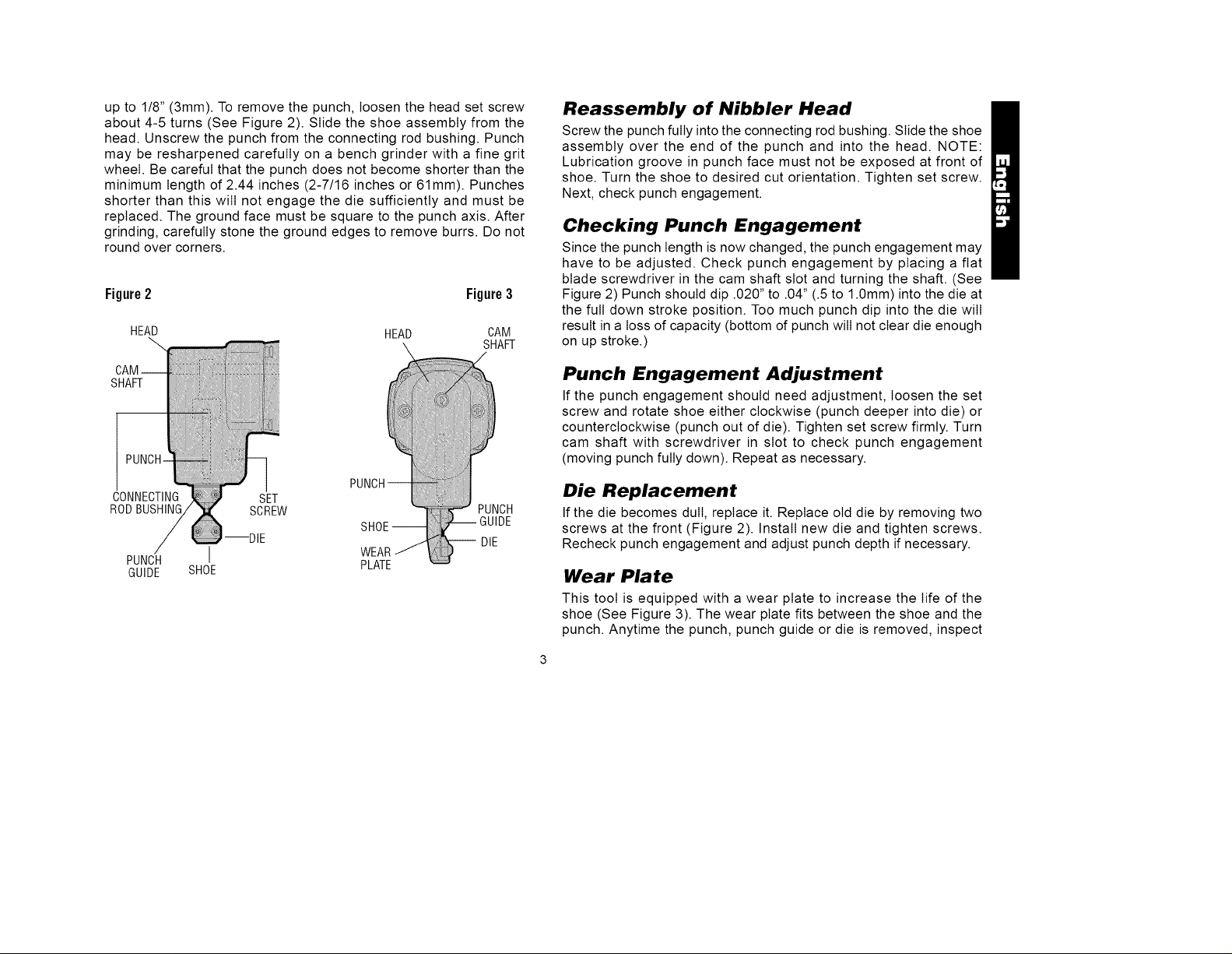
Figure2 Figure3
HEAD HEAD CAM
_ SHAFT
Reassembly of Nibbler Head
Screw the punch fully into the connecting rod bushing. Slide the shoe
assembly over the end of the punch and into the head. NOTE:
Lubrication groove in punch face must not be exposed at front of
shoe. Turn the shoe to desired cut orientation. Tighten set screw.
Next, check punch engagement.
Checking Punch Engagement
Since the punch length is now changed, the punch engagement may
have to be adjusted. Check punch engagement by placing a flat
blade screwdriver in the cam shaft slot and turning the shaft. (See
Figure 2) Punch should dip .020" to .04" (.5 to 1.0mm) into the die at
the full down stroke position. Too much punch dip into the die will
result in a loss of capacity (bottom of punch will not clear die enough
on up stroke.)
SHAFT
CONNECTING SET
RODBUSHING SCREW PUNCH
--DIE SHOE--
PUNCH I WEAR
GUIDE SHOE PLATE
i DIE
Punch Engagement Adjustment
If the punch engagement should need adjustment, loosen the set
screw and rotate shoe either clockwise (punch deeper into die) or
counterclockwise (punch out of die). Tighten set screw firmly. Turn
cam shaft with screwdriver in slot to check punch engagement
(moving punch fully down). Repeat as necessary.
Die Replacement
If the die becomes dull, replace it. Replace old die by removing two
screws at the front (Figure 2). Install new die and tighten screws.
Recheck punch engagement and adjust punch depth if necessary.
Wear Plate
This tool is equipped with a wear plate to increase the life of the
shoe (See Figure 3). The wear plate fits between the shoe and the
punch. Anytime the punch, punch guide or die is removed, inspect
Page 6

thewearplate.Ifitisworn,replaceit.
Toremovethewearplate,dissassembtethepunchguideanddie
(Figure3).Turncamshaftwithscrewdriversothatpunchisfullyup.
Slidethewearplatefrombehindthepunch.Insertanewwearplate.
Turnthecamshaftwithscrewdrivertomovepunchfullydown.
Replacepunchguideanddie.Checkpunchengagementtodie.
Adjustpunchengagement,ifnecessary.
Maintenance
DISCONNECT TOOL FROM POWER SUPPLY BEFORE
PERFORMING ANY MAINTENANCE. Check that the punch and
die are sharp. If either is dull, sharpen or replace. Check wear plate
and replace if worn. Keep the tool clean. Blow off periodically. Never
use solvents or harsh chemicals for cleaning non-metallic parts of the
tool. Use a clean, dry rag only. Periodically dip the shoe in oil. This is
a precision tool. Use it carefully and store it in a protected place.
Cleaning & Lubrication
Use only mild soap and damp cloth to clean the tool. Never let any
liquid get inside the tool; never immerse any part of the tool into a
liquid.
Self-lubricating bearings are used in the tool and periodic
relubrication is not required. In the unlikely event that service is ever
needed, service center addresses are packed with your tool.
Motor Brushes
Brush replacement should be performed by authorized service
centers or other qualified service organizations.
Important
To assure product SAFETY and RELIABILITY, repairs, maintenance
and adjustment (including brush inspection and replacement) should
be performed by authorized service centers or other qualified service
organizations, always using identical replacement parts.
Full Warranty
DEWALT heavy duty industrial tools are warranted for one year from
date of purchase. We will repair, without charge, any defects due to
faulty materials or workmanship. For warranty repair information,
call 1-800-4-DEWALT. This warranty does not apply to accessories or
damage caused where repairs have been made or attempted by
others. This warranty gives you specific legal rights and you may
have other rights which vary in certain states or provinces.
In addition to the warranty, DEWALT tools are covered by our:
30 DAY NO RISK SATISFACTION GUARANTEE
If you are not completely satisfied with the performance of your
DEWALT heavy duty industrial tool, simply return it to the participating
seller within 30 days for a full refund. Please return the complete unit,
transportation prepaid. Proof of purchase may be required.
Page 7

POURTOUTRENSEIGNEMENTSUPPL¢:MENTAIRESURCET
OUTILOUTOUTAUTREOUTILDEWALT,COMPOSERSANS
FRAISLENUM¢:RO:
1 800 4-DEWALT (1 800 433-9258)
IMPORTANTES
MESURES DE SJ CURITJ
(POUR TOUS LES OUTILS)
AVERTISSEMENT : Afin de reduire Ies risques d'incendie, de
secousses electriques ou de btessures Iorsqu'on utilise des outils
electriques, iI faut toujours respecter Ies mesures de securit6
suivantes.
TETE
BLOOAGE
-- BO[TIER SWITCH
-- MATRICE
I
ANNEAUDU
COUVERCLE
Grignoteusedecalibre16
IVIod_leDW897
t BOUTONDE
I VERROUILLAG
INTERRUPTEUR EDEL"
ABASCULEPADDLE INTERRUTEUR
LIRE TOUTES LES DIRECTIVES.
• BIEN DE:GAGER LA SURFACE DE TRAVAIL. Des surfaces et
des #tablis encombr#s peuvent _tre la cause de blessures.
• TENIR COMPTE DU MILIEU DE TRAVAIL. Prot#ger les outils
#lectriques de la pluie. Ne pas s'en servir dans des endroits
humides ou mouill#s. Bien #clairer la surface de travail.
• SE PROTE:GER CONTRE LES SECOUSSES E:LECTRIQUES.
Eviter tout contact avec des objets mis b la terre, comme des
tuyaux, radiateurs, cuisini#res, r#frig#rateurs et autres objets du
genre.
• ELOIGNER LES ENFANTS. Tousles visiteurs doivent _tre tenus
b I'#cart de I'aire de travail et il faut les emp_cher de toucher b
Ibutil ou au cordon de rallonge.
• RANGER LES OUTILS INUTILISES. IIfaut rangerles outils dans
un endroit sec, situ# en hauteur ou ferm# b cl& hors de la port#e
des enfants.
• NE JAMAIS FORCER L'OUTIL. Afin d'obtenir un rendement sDr
et efficace, utiliser I'outil b son rendement nominal.
• UTILISER L'OUTIL APPROPRIE:. Nejamais exigerd'un petitoutil
ou d'un accessoire le rendement d'un outil de fabrication plus
robuste. Se servir de Ibutil selon I'usage pr#vu (par exemple, ne
passe servir d'une scie circulaire pour couper des branches
d'arbres ou des b_Jches).
Page 8

• PORTER DES VETEMENTS APPROPRIES. Eviter de porter des
v_tements amples et des bijoux qui peuvent _tre happ_s par les
pi_ces en mouvement. Porter des gants de caoutchouc et des
chaussures _ semelle antid_rapante pour travailler _ I'ext_rieur.
Prot_ger la chevelure si elle est Iongue.
• PORTER DES LUNETTES DE SECURITE. Porter _galement un
masque respiratoire si le travail de coupe produit de la poussi_re.
• NE PAS MANIPULER LE CORDON DE FA_ON ABUSIVE. Ne
pas transporter I'outil par le cordon ni tirer sur ce demier pour le
d_brancher de laprise. Eloigner le cordon des sources de chaleur,
des flaques d'huile et des ar_tes tranchantes.
• ASSUJETTIR LA PIECE. Immobiliser la piece _/'aide de brides
ou d'un _tau. On peut alors se servir des deux mains pour faire
fonctionner Ibutil, ce qui est plus sDr.
• NE PAS DEPASSER SA PORTEE. Toujours demeurer dans une
position stable et garder son _quilibre.
• PRENDRE SOIN DES OUTILS. Conserverles outils propres pour
qu'ils donnent un rendement sup_rieur et sDr. Suivre les directives
concemant la lubrification et le remplacement des accessoires.
Inspecter r_gufi_rement le cordon de Ibutil et le faire r_parer au
besoin _ un atefier d'entretien autoris& Inspecter r_gufi_rement
les cordons de rallonge et les remplacer Iorsqu'ils sont
endommag_s. S'assurer que les poign_es sont toujours propres,
s_ches et libres de toute tache d'huile ou de graisse.
• DEBRANCHER LES OUTILS NON UTILISES. Respecter cette
mesure Iorsqu'on ne se sert pas de Ibutil, ou qu'on doit le r_parer
ou en changer un accessoire (comme une lame, un foret ou un
couteau).
• ENLEVER LES CLES DE REGLAGE. Prendre /'habitude de
v#rifier si les cl#s de r#glage ont #t# retirees avant de faire
d#marrer Ibutil.
• EVlTER LES DEMARRAGES ACCIDENTELS. Ne pas laisser le
doigt sur I'interrupteur Iorsqu'on transporte I'outil. S'assurer que
I'interrupteur est _ la position hors circuit Iorsqu'on branche I'outil.
• CORDONS DE RALLONGE PREVUS POUR L'EXTERIEUR.
Lorsque Ibutil est utilis# _ I'ext#rieur, ne se servir que d'un cordon
de rallonge congu pour I'ext#rieur et portant la mention appropri#e.
On trouve de plus amples renseignements sur les cordons de
rallonge _ la page 2.
• DEMEURER VIGILANT. Travailler avec vigilance et faire preuve
de bon sens. Ne pas se servir de Ibutil Iorsqubn est fatigu&
• V_=RIFIER LES PI_=CES ENDOMMAG_=ES. V_rifier I'alignement
et les attaches des pi#ces mobiles, le degr# d'usure des pi#ces et
leur montage, ainsi que tout autre facteur susceptible de nuire au
bon fonctionnement de I'outil. Faire r#parer ou remplacer tout
protecteur ou toute autre piece endommag#e dans un centre de
service autoris& sauf si le present guide fait mention d'un avis
contraire. Confier le remplacement de tout interrupteur d#fectueux
un centre de service autoris& Ne jamais se servir d'un outil
dont I'interrupteur est d#fectueux.
• NE PAS UTILISER les outils portatifs #lectriques dans des
endroits oD I'atmosph#re contient des vapeurs combustibles ou
explosives. Les #tincefles que produit le moteur en marche
pourraient enflammer ces produits.
CONSERVER CES MESURES
A TITRE DE REFERENCE.
Mesures relatives aux grignoteuses
1. Toujours porter des/unettes de s_curit_ et des gants protecteurs.
2. Porter des chaussures de s#curit# afin de prot#ger ses pieds des
d#bris m#talliques tranchants sur le plancher.
3. D#couper le mat#riau au plus au r#gime nominal de Ibutil. fl faut
se rappeler que I'#paisseur du mat#riau est inversement
proportionnefle au cafibre de I'outil (ainsi, un outil de cafibre 14
coupe des mat#riaux plus #pais qu'un outil de calibre 16). Un outil
de cafibre 14 accepte un mat#riau d'une #paisseur de 1,90 mm
Page 9

(0,075pc)etunoutildecalibre16,de1,52mm(0,060pc).
4.S'assurerquetouteslesvissontbienserr#es.Lesv#rifier
r#guli#rement.
5.D#brancherlbutilavantdeler#gler.
6.Nerieninsurerdanslesorificesducarterdumoteur.
7.S'assurerqueI'outilesttoujourspropre.Ennettoyerlesd#bris
m#talliquesetlapoussi#reenysoufflantdeFair.
8.Bienfixerlapiecedem#tal_ d#couper afin de I'emp_cher de
bouger pendant les travaux.
INTERRUPTEUR A BASCULE
Pour mettre I'outiI en marche, enfoncer I'interrupteur a bascule. Pour
I'arrOter, reI_cher I'interrupteur a bascule. On peut verrouilIer
I'interrupteur en mode de fonctionnement en enfongant Ie bouton de
verrouilIage qui se trouve pros de I'arriere de I'outiI tout en
maintenant enfonce I'interrupteur a bascule. Toujours s'assurer que
Figure 2 Figure 3
Tt_TE TETE ARBREA
ARBRE
A
CAME
DOUILLE
DELA BIELLE
POINOON- BLOCAGE
GUIDEPOUR
GABARIT
I-- MATRICE
BO[TIER
I
ANNEAUDU
COUVEROLE
VIS DE
POINOON--
\ CAME
IUIDEPOUR
-- GABARIT
-- MATRICE
I'outiI ne se trouve pas en mode de fonctionnement continu avant de
Ie brancher. Pour arrOter I'outiI Iorsque ce dernier est en mode de
fonctionnement continu, iI suffit d'enfoncer et de reI_cher
immediatement I'interrupteur.
Fonctionnement
METTRE UOUTIL HORS TENSION ET LE DI_BRANCHER AVANT
DE LE R#GLER Toujours porter des Iunettes de securit6 et des
gants protecteurs.
Lubrifier Ia surface du materiau avec de I'huile. La grignoteuse est
congue pour decouper du metal plat et I6gerement onduI&
L'outiI est monte en usine avec Ie poingon en position avant pour
decouper du metaI plat et I6gerement onduI&
La tote de I'outiI se place darts I'une de trois positions : vers la
gauche, vers I'avant et vers Ia droite (fig. 2). Pour faire tourner Ia tote,
desserrer Ia vis de btocage. Faire tourner Ia tote darts Ia position
voulue. NOTE: Ne pas faire tourner Ia tote sur elIe-mOme au risque
de modifier I'insertion du poingon darts Ia matrice.
Faire tourner Ie boftier darts Ia tote et faire toumer Ia vis de btocage
jusqu'a ce que Ia vis s'instalIe darts Ie creux du patin. Bien serrer Ia
vis de btocage. Verifier r6gulierement si Ia vis est bien settee.
La tote de Ia grignoteuse est congue pour s'inserer darts un trou
d'un diametre de 19 mm (3/4 pc) afin de pouvoir decouper au milieu
de Ia piece. Le grignotage se fait darts un sens ou darts I'autre darts
Ie trou. IIy a un indicateur de Ia Iargeur du poingon a I'avant du boftier
permettant a I'utilisateur de pouvoir suivre une Iigne (fig. 3).
Le dessous du boftier comporte un guide pour gabarit de 13 mm
(0,51 pc) de diametre afin de pouvoir utiliser des gabarits.
L'epaisseur du gabarit et du materiau doit se situer entre 5et 6,5 mm
(13/64 pc et 1/4 pc). La forme du gabarit doit se trouver a 2,5 mm
(1 pc) de Ia forme a grignoter. II faut guider I'outiI de sorte que Ie
diametre exterieur (13 mm ou 0,51 pc) du boftier repose contre Ie
gabarit.
Page 10

Remplacement du poin_on
Ne jamais utiliser un poin(_on emouss& On peut affQter Ies poin(_ons
jusqu'a une Iongueur minimale de 69 mm (2,72 po). Des poin(_ons
trop courts ne servent pas. Pour enlever Ie poin(_on, desserrer Ia vis
de btocage de Ia t_te d'environ 4 a 5 tours (fig. 2). Faire gtisser Ie
boftier hors de Ia t_te. Devisser Ie poin(_on de Ia douilIe de Ia bielle.
IIfaut affQter avec soin Ies poin(_ons a I'aide d'une meuleuse d'etabti
munie d'une meule a fine granulosit& Ne pas trop raccourcir Ie
poin(_on. Un poin(_on trop court ne s'insere pas bien dans Ia matrice
et iIfaut teremptacer. La face meulee dolt _tre perpendiculaire a I'axe
du poin(_on. Apres Ie meulage, ebarber soigneusement Ies rebords
aff0tes. Ne pas en arrondir Ies coins.
Remontage de la t#te de la grignoteuse
Visser Ie poin(_on a fond dans Ia douilIe de Ia bielIe. Faire gtisser Ie
boftier sur I'extremit6 du poin(_on et dans Ia t_te. Faire tourner Ia t_te
dans Ia position de coupe vouIue. Bien serrer Ia vis de btocage.
Enfin, verifier I'insertion du poingon.
V_rification de I'insertion du poin_on
Puisque Ia Iongueur du poin(_on est differente, iI faut peut-_tre regter
I'insertion du poingon. La verifier en plagant un tournevis a Ia me
plate dans Ia fente de I'arbre a came et en faisant tourner I'arbre
(fig. 2). Le poingon devrait s'affaisser de 0,5 mm a 1,15 mm (de
0,02 po a 0,06 po) dans Ia matrice a Ia position Ia plus basse de Ia
course. Lorsque I'affaissement du poingon dans Ia matrice est trop
grand, iIen resulte une perte de rendement (Ie bout du poingon ne se
degage pas suffisamment de Ia matrice au plus haut de Ia course).
R_glage de I'insertion du poin_on
Lorsqu'iI faut regter I'insertion du poin(_on, desserrer Iavis de btocage
et faire tourner Ie patin dans un sens horaire (Ie poingon enfonce
dans Ia matrice) ou dans Ie sens antihoraire (Ie poin(_on hors de Ia
matrice). Bien serrer Ia vis de btocage. Faire tourner I'arbre a came
I'aide du tournevis dans Ia fente afin de verifier I'insertion du poin(_on
(en abaissant comptetement Ie poin(_on). Repeter au besoin.
Remplacement de la matrice
Lorsque Ia matrice est emoussee, Ia remplacer. Remplacer
I'ancienne matrice en poussant I'anneau du couvercIe vers Ie haut,
hors de Ia rainure. Se servir d'un poingon de gtissement pour faire
sortir la tige de retenue du dessous de I'anneau du couvercIe. Retirer
Ia matrice de I'arbre-porteur. Installer une nouveIIe matrice sur
I'arbre-porteur. Aligner Ie trou de Ia matrice sur Ia rainure de I'arbre-
porteur. Installer Ia tige. Enclencher I'anneau du couvercIe dans Ia
rainure du dessus de Ia matrice.
Entretien
D¢:BRANCHER L'OUTIL AVANT D'EFFECTUER TOUT TRAVAIL
D'ENTRETIEN. S'assurer que Ie poingon et Ia matrice sont affQtes.
Lorsque I'un d'eux est emousse, I'affQter ou le remptacer. S'assurer
que I'outiI est propre. UtiIiser reguIierement de I'air pour en souffler
Ies saletes. Ne jamais se servir de solvants ni de produits chimiques
puissants pour nettoyer Ies composants non metalIiques de I'outiI.
UtiIiser seuIement un chiffon propre et sec. Tremper reguIierement te
patin dans de I'huile. IIs'agit d'un outiI de precision. S'en servir avec
soin et Ie ranger dans un endroit protege.
Nettoyage et lubrification
Nettoyer I'outiI seulement a I'aide d'un savon doux et d'un Iinge
humide. Ne Iaisser aucun Iiquide s'infiltrer dans I'outiI et ne jamais
immerger I'outiI.
L'outiI est monte sur des rouIements autoIubrifiants qui ne requierent
pas de Iubrification periodique. Dans Ie cas peu probable o_ I'outiI
necessiterait de I'entretien, Ia Iiste des centres de service se trouve
dans I'emballage.
Page 11

Balais du moteur
II faut confier le remptacement des balais au personnel d'un centre
de service autorise.
Important
Pour assurer Ia S¢:CURIT¢: D'EMPLOI et ta FIABILIT¢: de I'outiI, n'en
confier Ia reparation, I'entretien et Ies rajustements (y compris
I'inspection et Ie remplacement des balais) qu'au personnel d'un
centre de service DEWALT ou d'un atelier d'entretien autorise
n'utiIisant que des pieces de rechange identiques.
Accessoires
Les accessoires recommandes pour cet outiI sont vendus chez Ies
detaiIIants ou au centre de service de Ia region. Pour trouver un
accessoire, communiquer avec Ie detaiIIant ou Ie centre de service
de Ia region.
Z_MISE EN GARDE: L'utilisation de tout autre accessoire non
recommande pour I'outiI peut _tre dangereuse.
Garantie complete
Les outils industriels de service intensif DEWALT sont garantis
pendant un an a partir de Ia date d'achat. Toute piece d'un outiI
DEWALT qui s'averait defectueuse en raison d'un vice de matiere ou
de fabrication sera repar6e ou remptacee sans frais. Pour obtenir de
plus ampIes renseignements sur Ies reparations couvertes par Ia
garantie, composer Ie 1 (800) 4-DEWALT (! (800) 433-9258). La ga
rantie ne couvre pas Ies accessories ni Ies reparations tentees ou
effectuees par des tiers. Les modaIites de Ia presente garantie
donnent des droits Iegaux specifiques. L'utiIisateur peut egaIement
se prevaIoir d'autres droits seIon I'etat ou Ia province qu'iI habite.
En outre, Ia garantie suivante couvre Ies outiIs DEWALT.
GARANTIE DE SATISFACTION DE 30 JOURS OU ARGENT REMIS
Si, pour quelque raison que ce soit, I'outiI industrieI de service intensif
DEWALT ne donne pas entiere satisfaction, iI suffit de Ie retourner
chez Ie marchand participant dans Ies 30 jours suivant Ia date
d'achat afin d'obtenir un remboursement comptet. II faut retourner,
port paye, I'outiI comptet. On peut exiger une preuve d'achat.
Imported by / Importe par
DEWALT Canada Inc.
100 Central Ave.
BrockvilIe (Ontario) K6V 5W6
Voir la rubrique "Outils _lectriques"
des Pages Jaunes
pour le service et les ventes,
Page 12

PUNZON
OABEZA
PRISIONERO I
-- CARCAZA
--DADO
i
ARILL0DE
OUBIERTA
Epecificaciones (DW897)
Tensi6n de alimentaci6n 120 V
Potencia nominal: 225 W
Frecuencia de operaci6n: 60 Hz
Consumo de corriente: 6,5 A
DW8g8
CortadorasdeI_mina
Calibre16
INTERRUPTORDE
PALETA
\
BOTONDE
ENOENDID0
PERMANENTE
Instrucciones importantes de seguridad
Z_ ADVERTENCIA: Es indispensable sujetarse a Ias precauciones
basicas de seguridad, con Ia finalidad de reducir el peligro de
incendio, choque electrico y Iesiones personales, en todas Ias
ocasiones en que se utilicen herramientas electricas. Entre estas
precauciones se incluyen Ia siguientes:
LEA TODAS LAS INSTRUCCIONES
Doble aislamiento
Las herramientas DOBLEMENTE aisIadas se hart eIaborado de
manera integral con dos capas separadas de aislamiento electrico o
una capa dobte de aislamiento entre usted y el sistema electrico
que contienen. Las herramientas construidas con este sistema de
aislamiento no requieren conectarse a tierra. Como resultado su
herramienta esta equipada con una clavija de dos patas que Ie
permite emptear cordones de extensi6n sin preocuparse por tener
una conexi6n a tierra.
NOTA: El dobte aislamiento no substituye a Ias precauciones
normales de seguridad cuando se opera esta herramienta. La
finalidad de este sistema de aislamiento es ofrecer a usted
protecci6n afiadida contra Iesiones resultantes de falIas en el
aislamiento electrico interno de Ia herramienta.
/_ PRECAUClON: UTILICE SOLAMENTE REFACCIONES ORIG-
INALES CUANDO HAGA SERVICIO a cualquier herramienta.
Repare o reemptace los cordones electricos dafiados.
Clavijas polarizadas
Se emplean clavijas polarizadas (con una pata mas ancha que Ia
otra) para reducir los riesgos de choque electrico. Cuando el cord6n
electrico cuente con este tipo de clavija, ajustara en un contacto
polarizado solamente de una manera. Si Ia clavija no ajusta
10
Page 13

comptetamente en su contacto, inviertala. Si aQn asi no ajusta, Ilame
a un electricista calificado para que Ie instale un contacto polarizado
apropiado. No modifique o haga cambios en Ia clavija por ningQn
motivo.
Instrucciones de seguridad para todas
las herramientas
• CONSERVE LIMPIA LA ZONA DE TRABAJO. Las superficies y
los bancos con objetos acumulados en desorden propician los
accidentes.
• OTORGUE PRIORIDAD A LA ZONA DE TRABAJO. No deje/as
herramientas el_ctricas expuestas a la /luvia. No las utifice en
lugares inundados o mojados. Conserve bien iluminada la zona de
trabajo. No utifice la herramienta en presencia de I[quidos o gases
inflamables.
• PROTEJASE CONTRA EL CHOQUE ELECTRICO. Evite el
contacto corporal con superficies aterrizadas, pot ejemplo,
tuber[as, radiadores, antenas y gabinetes de refrigeraci6n.
• CONSERVE APARTADOS A LOS NII_IOS. No permita que los
visitantes toquen las herramientas o los cables de extensi6n.
Todos los visitantes deben estar alejados de la zona de trabajo.
• GUARDE LAS HERRAMIENTAS QUE NO EMPLEE. Las
herramientas que no se utifizan deben guardarse en un lugar seco
y elevado o bajo/lave -- fuera del alcance de los ni_os.
• NO FUERCE LA HERRAMIENTA. Esta cumplir_ su funci6n mejor
y con m_s seguridad a la velocidad y la presi6n para las que se
dise_6.
• EMPLEE LA HERRAMIENTA ADECUADA. No fuerce a una
herramienta peque_a o a sus dispositivos de montaje en un
trabajo de tipo pesado. No emplee la herramienta en una tarea
para la que no se dise_6.
• VlSTASE DE LA MANERA ADECUADA. No use ropas o art[culos
de joyer[a flojos, pues podr[an quedar atrapados por las partes
m6viles de/as herramientas. Se recomienda el empleo de guantes
de caucho y calzado antiderrapante cuando se trabaje al aire fibre.
CDbrase bien la cabeza para sujetarse el cabe/lo si Io tiene largo.
• COLOQUESE ANTEOJOS DE SEGURIDAD. P6ngase tambi_n
una mascari/la contra el polvo si Io produce la operaci6n que va a
efectuar.
• TENGA CUIDADO CON EL CORDON ELECTRICO. Nunca
levante la herramienta tom_ndola pot el cord6n, ni tire de _ste para
desconectarlo del enchufe. Ap_rtelo del calor y los objetos
cafientes, /as substancias grasosas y los bordes cortantes.
• ASEGURE LOS OBJETOS SOBRE LOS QUE TRABAJE. Utifice
prensas o tomi/los de banco para sujetar los objetos sobre los
que va a trabajar. Esto ofrece mayor seguridad que sujetar los
objetos con la mano, y adem_s deja fibres ambas manos para
operar la herramienta.
• CONSERVE EL EQUILIBRIO. Conserve en todo momento bien
apoyados los pies, Io mismo que el equifibrio.
• CUIDE SUS HERRAMIENTAS. Conserve sus herramientas
afiladas y fimpias para que funcionen mejor y con mayor
seguridad. Siga las instrucciones para lubricaci6n y cambio de
accesorios de su unidad. Revise peri6dicamente el cord6n
el_ctrico y h_galo reparar o reemplazar por un centro de servicio si
est_ da_ado. Cambie los cordones de extensi6n si est_n da_ados.
Conserve las empu_aduras secas, fimpias y fibres de aceite y
grasa.
• DESCONECTE YAPAGUE LAS HERRAMIENTAS cuando no/as
use, antes de darles servicio y cuando cambie accesorios, tales
como discos, brocas y otros dispositivos de corte.
• RETIRE LAS LLAVES DE AJUSTE Y DE TUERCAS. Adquiera
el h_bito de asegurarse que se han retirado /as /laves de ajuste
de/as herramientas antes de accionarlas.
• EVlTE QUE LA HERRAMIENTA SE ACCIONE ACCIDENT-
ALMENTE. Nunca sostenga una herramienta que est_ conectada
con el dedo en el interruptor. AsegDrese que el interruptor est_ en
posici6n de "apagado" antes de conectar la unidad.
11
Page 14

CORDONESDEEXTENSION.Asegbresequesucord6nde
extensi6nest#enbuenascondiciones.Cuandoutiliceuncord6n
deextensi6n,asegbresequetengaelcafibresuficientepara
soportarlacorrientenecesariaparasuherramienta.Uncord6n
el#ctricoconcalibreinsuficientecausar_unacaidaenelvoltajede
laline&resultandoenp#rdidadepotenciaysobrecalentamiento.
Latablasiguienteilustraelcalibrecorrectoquedebeutilizarsede
conformidadconlaIongituddelcord6nyelamperajedescritopor
laplacadeidentificaci6n.Sitienealgunaduda,utiliceelcablecon
elcalibresiguiente(mayor).Mientrasm_schicoseaelnbmero,
mayorser_sucalibre.
VoltsLongitud total del cord6n en metro
120V 0-7.62
240V 0-15.24
AMPERAJE
Mas No mas Calbre del cord6n
de de
0 6
6 10
CORDONES DE EXTENSION PARA INTEMPERIE. Cuando
opere su herramienta a la intemperie, utilice bnicamente cordones
de extensi6n dise_ados y marcados para este fin.
NO SE DISTRAIGA. Conc#ntrese en Io que est_ haciendo.
Recurra al sentido combn. No opere ninguna herramienta si est_
fatigado.
VERIFIQUE LAS PARTES DAI_IADAS. Antes de seguir
empleando cualquier herramienta, es indispensable verificar con
mucho cuidado que las guardas u otras partes da#adas puedan
operar de la manera adecuada para cumpfir con su funci6n.
Verifique la alineaci6n de las partes m6viles, la firmeza con que
deben encontrarse sujetas a sus montaduras, /as partes rotas, /as
propias montaduras y cualesquiera otros detalles que pudieran
afectar la operaci6n de la herramienta. Las guardas y otras partes
Calibre minimo para cordones de extensi6n
10 12
1212 - 16
7.63-15.24 15.25-30.48 30.4945.72
15.25-30.48 30.49-60.96 60.97-91.44
18 16 1614
18 16 1412
16 16 14
14 12 No Recomendado
que se encuentren da#adas deber_n cambiarse o repararse en un
centro de servicio autorizado, a menos que se diga otra cosa en
el manual del usuario. Haga que se cambien los interruptores
da#ados en un centro de servicio autorizado. No emplee ninguna
herramienta que tenga estropeado o inutilizado el interruptor.
Reglas de operaci6n para cortadoras de
lamina
1. Uti/ice siempre anteojos de seguridad as/ como guantes
protectores.
2. Use calzado de seguridad para proteger sus pies de rebabas
met_licas afiladas que pudieran caer al suelo.
3. Corte material hasta o pot debajo de la capacidad especificada.
Recuerde que el espesor del material aumenta mientras que el
Figara 2 Figara 3
CABEZA CABEZA ARBOL
DE
LEVAS
BUJEDE PRISIONERO
VARILLADE GUIADE
OONEXION
J-- DADO -- DADO
GUIADE I
PUNZON ZAPATA
l
ZAPATA -- PUNZON
PLAOA
DESGASTE
DELEVAS
12
Page 15

nDmero de cafibre disminuye (el calibre 14 tiene mayor espesor
que el calibre 16). El espesor del calibre 14 es de 1,90 mm
(0,075"); el espesor del calibre 16 es de 1,52 mm (0,060").
4. Conserve apretados todos los tornillos. Revise peri6dicamente
que no se hayan aflojado.
5. Desconecte la herramienta antes de efectuar cualquier ajuste.
6. No ponga nada dentro de la abertura de la carcaza del motor.
7. Conserve limpia la herramienta. Sopletee cualquier residuo
met_lico de la herramienta, as[ como la mugre.
8. Asegure con firmeza la pieza de metal que vaya a cortar para
evitar movimientos durante la operaci6n.
Interruptor de paleta
Optima el interruptor de paIeta para encender Ia unidad. Para
apagarta, Iibere el interruptor. El interruptor puede asegurarse para
operaci6n continua accionando el bot6n que se encuentra cerca de
Ia parte posterior de Ia herramienta al mismo tiempo que se oprime
Ia paleta. Asegerese siempre que Ia herramienta no este en posici6n
de encendido permanente antes de conectarta. Para apagar Ia
herramienta cuando el interruptor se encuentra en esta posici6n,
optima y Iibere Ia paleta una vez.
Operaci6n
APAGUE Y DESCONECTE LA HERRAMIENTA DE LA TOMA DE
CORRIENTE ANTES DE HACER CUALQUIER AJUSTE. Utilice
siempre gafas de seguridad y guantes protectores.
Lubrique Ia superficie deI material con aceite. La cortadora esta
disefiada para trabajar con metal piano y corrugado con poca
profundidad.
La herramienta se ensambla en Ia fabrica con el punz6n orientado
hacia adelante para cortar metal piano y corrugado con poca
profundidad.
La cabeza puede alinearse en tres posiciones: a Ia izquierda, hacia
adelante y a Ia derecha (observe Iafigura 2). Aftoje el prisionero para
girar Ia cabeza. Gire Ia cabeza hacia Ia direcci6n que desee.NOTA:
No gire Ia cabeza en un circulo compteto ya que esto cambiara Ia
alineaci6n deI punz6n y el dado.
Gire Ia carcaza de Ia cabeza y atornilIe el prisionero hasta sentir
que se acomoda en una cavidad en Ia zapata. Apriete el prisionero
con firmeza. Revise peri6dicamente que este tornilIo este apretado.
La cabeza de Ia cortadora esta disefiada para acoptarse a traves de
un orificio de 19 mm (3/4") para iniciar un corte a Ia mitad de una
pieza. El corte se puede hacer en cualquier direcci6n a partir de
este orificio. AI frente de Ia carcaza se encuentra un indicador de
ancho de punz6n que permite que el usuario siga una Iinea de cerca
(figura 3).
La parte inferior de Ia carcaza tiene una guia de 13 mm (0,51") de
diametro que Ie permite el empleo de plantilIas. El espesor de Ia
ptantilIa debe set taI que el espesor total de esta junto con Ia pieza
de trabajo sea de 5 a 6,5 mm (13/64" a 1/"). El contorno de Ia ptantilIa
debe estar a 2,5 mm (0,1") deI contomo pot recortar. Debe guiarse Ia
herramienta de manera que el diametro exterior de Ia carcaza (13
mm o 0,51") descanse en Ia ptantilIa.
Cambio de punzones
Nunca corte con un punz6n sin fiIo. Los punzones pueden afiIarse
hasta que Ileguen a una Iongitud de 69 mm (2,72"). Cuando son mas
cortos son inQtiles. Para sacar el punz6n, afloje el prisionero
aproximadamente de 4 a 5 vueltas (observe Ia figura 2). Deslice Ia
carcaza de Ia cabeza. DestomilIe el punz6n deI buje conector de
varilIa. El punz6n puede afilarse con cuidado en un esmeriI de banco
con piedra de grano fino. Tenga cuidado de no permitir que el punz6n
Ilegue a una Iongitud menor a Ia minima. Los punzones mas cortos
no alcanzaran debidamente el dado y deberan reemplazarse. La
cara deI esmeriI debera estar a escuadra con el eje deI punz6n.
Despues de esmerilar, asiente cuidadosamente los filos para
eliminar rebabas. No redondee Ias esquinas.
13
Page 16

Ensamblaje de la cabeza de la cortadora
AtornilIe el punz6n comptetamente dentro deI buje de conexi6n de
variIIa. DesIice Ia carcaza sobre el extremo deI punz6n y hacia dentro
de Ia cabeza. Gire Ia cabeza hacia Ia orientaci6n de corte que desee.
Apriete el prisionero y a continuaci6n, revise el acopIamiento deI
punz6n con el dado.
Revisi6n del acoplamiento del punz6n
Ya que Ia Iongitud deI punz6n ha cambiado, puede requerirse ajustar
el acoptamiento. Revise el acoptamiento deI punz6n coIocando un
destornilIador de punta ptana en Ia ranura deI eje de Ia Ieva (observe
Ia figura 2). El punz6n debe penetrar de 0,5 a 1,15 mm (0,2" a 0,6")
dentro deI dado en Ia posici6n de despIazamiento compIeto.
Demasiada penetraci6n en el dado puede originar perdida de
capacidad (Ia parte inferior deI punz6n no despejara suficientemente
el dado en Ia carrera hacia arriba).
Ajuste del acoplamiento del punz6n
Si el acoptamiento deI punz6n requiere ajustarse, afloje el prisionero
y gire Ia zapata en el sentido de Ias manecilIas deI reloj (mayor
penetraci6n en el dado) o en sentido contrario a Ias manecilIas deI
reloj (hacia fuera deI dado). Apriete el prisionero con firmeza. Gire el
eje de Ia Ieva con un destornilIador en Ia ranura para verificar Ia
penetraci6n deI punz6n (moviendo el punz6n comptetamente hacia
abajo). Repita cuanto sea necesario.
Cambio del dado
Si el dado Ilega a estar romo, reemptacelo. Cambie el dado viejo
empujado el arilIo de Ia cubierta hacia arriba y hacia afuera deI canal
deI dado. Retire el perno reten de debajo deI arilIo de Ia cubierta con
un martilIo punz6n. Tire deI dado hacia fuera deI eje transportador.
Instale un dado nuevo en el eje transportador. Haga coincidir el
orificio en cruz deI dado con el canal deI eje transportador. Instale el
perno. CoIoque el ariIIo sobre el dado en el canal hecho para este fin.
Mantenimiento
Utilice _nicamente un jab6n suave y un trapo h_medo para Iimpiar
Ia herramienta. Nunca permita que se introduzca ningQn Iiquido en Ia
herramienta, ni sumerja ninguna parte de esta en ningQn Iiquido.
Se han empteado baleros auto Iubricantes en Ia fabricaci6n de esta
herramienta y no se requiere de lubricaci6n peri6dica. En el
improbable caso que su herramienta IIegase a requerir servicio,
IIeveIa a un centro de servicio autorizado.
Accesorios
Dispone usted de los accesorios para su herramienta por un cargo
adicional con su distribuidor local autorizado.
EL ACCESORIO DEBE ESTAR CLASlFICADO PARA UTILIZARSE
A UNA VELOClDAD IGUAL O MAYOR QUE LAS R.P.M.
SENALADAS EN LA PLACA DE IDENTIFICAClON DE LA
HERRAMIENTA QUE SE ESTE EMPLEANDO.
Si necesita ayuda para encontrar cuaIquier accesorio, por favor
comuniquese aI 326-7100.
Z_PRECAUClON: El empleo de cualquier otro accesorio no
recomendado para utilizarse con esta herramienta puede ser
peligroso.
Importante
Para garantizar Ia SEGURIDAD y Ia CONFIABILIDAD deI producto,
deberan hacerse reparaciones, mantenimiento y ajustes (incluyendo
revisi6n y cambio de los carbones) por centros autorizados de
servicio u otras organizaciones calificadas que empIeen siempre
refacciones identicas
14
Page 17

PARA REPARACION Y SERVICIO DE SUS HERRAMIENTAS
ELECTRICAS FAVOR DE DIRIGIRSE AL CENTRO DE SERVICIO MAS
CERCANO
CULIACAN
Av. Nicolas Bravo #1063 Sur (91 671 )242 10
GAUDALAJARA
Av. La Paz #1779 (91 3) 826 69 78.
MEXICO
Eje Lazaro Cardenas No. 18 Local D, Col. Obrera 588-9377
MERIDA
Calle 63 #459-A (91 99) 23 54 90
MONTERREY
Av. Francisco I. Madero Pte. 1820-A (91 83) 72 11 25
PUEBLA
17 Norte #205 (91 22) 46 37 14
QUERETARO
Av. Madero 139 Pte. (91 42) 14 16 60
SAN LOUIS POTOSI
Pedro Moreno #100 Centro (91 48) 14 25 67
TORREON
Blvd. Independencia, 96 pte. (91 17) 16 52 65
VERACRUZ
Prolongaci6n Diaz Miron #4280 (91 29) 21 70 16
VILLAHERMOSA
Constitucion 516-A (91 93) 12 53 17
PARA OTRAS LOCALIDADES LLAME AL: 326 7100
Garantia Completa
Las herramientas industriales DEWA/T estan garantizadas durante un a_o a
partir de la fecha de compra. Repararemos, sin cargos, cualquier falla debida
a material o mano de obra defectuosos. Pot favor regrese la unidad completa,
con el transporte pagado, a cualquier Centro de Servicio para Herramientas
Industriales de DEWA/T o a las estaciones de servicio autorizado enlistadas
bajo "Herramientas Electricas" en la Secci6n Amarilla. Esta garantia no se
aplica a los accesorios ni a da_os causados pot reparaciones efectuadas
pot terceras personas. Esta garantia le otorga derechos legales especificos,
y usted puede tener otros derechos que pueden variar de estado a estado.
En adici6n a la garantia, las herramientas DEWALT estan amparadas pot
nuestra:
GARANTJA DE SATISFACCION SIN RIESGO POR 30 DJAS
Si usted no se encuentra completamente satisfecho con el desempe_o de
su herramienta industrial DEWALT, sencillamente devuelvala a los
vendedores participantes durante los primeros 30 dias despues de la fecha
de compra para que le efectQen un reembolso completo. Pot favor regrese
la unidad completa, con el transporte pagado. Se puede requerir prueba de
compra.
IMPORTADO: DEWALT S.A. DE C.V.
BOSQUES DE CIDROS ACCESO RADIATAS NO. 42
COL. BOSQUES DE LAS LOMAS.
05120 MEXICO, D.F
TEL. 326-7100
Para servicioy ventas consulte
"HERRAMIENTAS ELECTRICAS"
en la seccion amarilla, SECCIQN
A_M_RJLLA
15
Page 18

DEWALTIndustrialToolCompany,P.O.Box158,626HanoverPike,Hampstead,MD21074
DW897/897-220 Copyright©1997
PrintedinCountryMAY97-1)
FormNo.384328
 Loading...