

Page 1

DEWALT Industrial Tool Company, P.O. Box 158, 626 Hanover Pike, Hampstead, MD 21074 Printed in Country MAY97-1) Form No. 384328
DW897/897-220 Copyright © 1997
DW 897-220 5/2/02 1:48 PM Page 2
Page 2

INSTRUCTION MANUAL
GUIDE D'UTILISATION
MANUAL DE INSTRUCCIONES
DW897/DW897-220
16 Gauge Nibbler
Grignoteuse de calibre 16
Cortadora de lamina calibre 16
INSTRUCTIVO DE OPERACIÓN, CENTROS DE SERVICIO Y PÓLIZA
DE GARANTÍA. ADVERTENCIA: LÉASE ESTE INSTRUCTIVO ANTES
DE USAR EL PRODUCTO.
DW 897-220 5/2/02 1:48 PM Page 3
Page 3

IMPORTANT SAFETY
INSTRUCTIONS (FOR ALL TOOLS)
WARNING: When using electric tools, basic safety precautions
should always be followed to reduce risk of fire, electric shock, and
personal injury, including the following:
READ ALL INSTRUCTIONS
Double Insulation
Double insulated tools are constructed throughout with two separate
layers of electrical insulation or one double thickness of insulation
between you and the tool’s electrical system. Tools built with this
insulation system are not intended to be grounded. As a result, your
tool is equipped with a two prong plug which permits you to use
extension cords without concern for maintaining a ground
connection.
NOTE: Double insulation does not take the place of normal safety
precautions when operating this tool. The insulation system is for
added protection against injury resulting from a possible electrical
insulation failure within the tool.
CAUTION: WHEN SERVICING USE ONLY IDENTICAL REPLACEMENT PARTS. Repair or replace damaged cords.
Polarized Plugs(DW897)
Polarized plugs (one blade is wider than the other) are used on
equipment to reduce the risk of electric shock. When provided, this
plug will fit into a polarized outlet only one way. If the plug does not
fit fully into the outlet, reverse the plug. If it still does not fit, contact a
qualified electrician to install the proper outlet. Do not change the
plug in any way.
English
IF YOU HAVE ANY QUESTIONS OR COMMENTS ABOUT THIS
OR ANY D
EWALT TOOL, CALL US TOLL FREE AT:
1-800-4-DEWALT (1-800-433-9258)
DW897/DW897-220 16-Gauge
Profile Nibbler
PADDLE SWITCH
SWITCH
LOCK
BUTTON
PUNCH
GUIDE
HEAD
SHOE
DIE
PUNCH
DW 897-220 5/2/02 1:48 PM Page 4
Page 4

For All Tools:
• KEEP WORK AREA CLEAN. Cluttered areas and benches invite
injuries.
• CONSIDER WORK AREA ENVIRONMENT. Don’t expose power
tools to rain. Don’t use power tools in damp or wet locations. Keep
work area well lit.
• GUARD AGAINST ELECTRIC SHOCK. Prevent body contact
with grounded surfaces; for example, pipes, radiators, ranges,
and refrigerator enclosures.
• KEEP CHILDREN AWAY. All visitors should be kept away from
work area. Do not let visitors contact tool or extension cord.
• STORE IDLE TOOLS. When not in use, tools should be stored in
dry, and high or locked-up place — out of reach of children.
• DON’T FORCE A TOOL. It will do the job better and safer at the
rate for which it was intended.
• USE RIGHT TOOL. Don’t force small tool or attachment to do the
job of a heavy duty tool. Don’t use tool for purpose not intended; for
example, don’t use circular saw for cutting tree limbs or logs.
• DRESS PROPERLY. Do not wear loose clothing or jewelry. They
can be caught in moving parts. Rubber gloves and non-skid
footwear are recommended when working outdoors. Wear
protective hair covering to contain long hair.
• USE SAFETY GLASSES. Also use face or dustmask if operation
is dusty.
• DON’T ABUSE CORD. Never carry tool by cord or yank it to
disconnect from receptacle. Keep cord from heat, oil, and sharp
edges.
• SECURE WORK. Use clamps or a vise to hold work. It’s safer than
using your hand and it frees both hands to operate tool.
• DON’T OVERREACH. Keep proper footing and balance at all
times.
• MAINTAIN TOOLS WITH CARE. Keep tools sharp and clean for
better and safe performance. Follow instructions for lubricating and
changing accessories. Inspect tool cords periodically and if
damaged have repaired by authorized service facility. Inspect
extension cords periodically and replace if damaged. Keep
handles dry, clean, and free from oil and grease.
• DISCONNECT OR LOCK OFF TOOLS when not in use, before
servicing, and when changing accessories, such as blades, bits,
cutters.
• REMOVE ADJUSTING KEYS AND WRENCHES. Form habit of
checking to see that keys and adjusting wrenches are removed
from tool before turning it on.
• AVOID UNINTENTIONAL STARTING. Don’t carry plugged-in tool
with finger on the switch. Be sure the switch is off when plugging
in.
• EXTENSION CORDS. Make sure your extension cord is in good
condition. When using an extension cord, be sure to use one
heavy enough to carry the current your product will draw. An
undersized cord will cause a drop in line voltage resulting in loss
of power and overheating. The following table shows the correct
size to use depending on cord length and nameplate ampere
rating. If in doubt, use the next heavier gage. The smaller the gage
number, the heavier the cord.
Minimum Gage for Cord Sets
Volts Total Length of Cord in Feet
120V 0-25 26-50 51-100 101-150
240V 0-50 51-100 101-200 201-300
Ampere Rating
More Not more AWG
Than Than
0-6 18161614
6 - 10 18 16 14 12
10-1216161412
12 - 16 14 12 Not Recommended
• STAY ALERT. Watch what you are doing. Use common sense.
Do not operate tool when you are tired.
• OUTDOOR USE EXTENSION CORDS. When tool is used
outdoors, use only extension cords intended for use outdoors and
so marked.
1
English
DW 897-220 5/2/02 1:48 PM Page 1
Page 5

2
• CHECK DAMAGED PARTS. Before further use of the tool, a
guard or other part that is damaged should be carefully checked
to determine that it will operate properly and perform its intended
function. Check for alignment of moving parts, binding of moving
parts, breakage of parts, mounting, and any other conditions that
may affect its operation. A guard or other part that is defective
should be properly repaired or replaced by an authorized service
center unless otherwise indicated elsewhere in this instruction
manual. Have defective switches replaced by authorized service
center. Do not use tool if switch does not turn it on and off.
• DO NOT OPERATE portable electric tools near flammable liquids
or in gaseous or explosive atmospheres. Motors in these tools
normally spark, and the sparks might ignite fumes.
• CAUTION: When drilling or driving into walls, floors or wherever
live electrical wires may be encountered, DO NOT TOUCH ANY
METAL PARTS OF THE TOOLS! Hold the tool only by insulated
grasping surfaces to prevent electric shock if you drive into a live
wire.
SAVE THESE INSTRUCTIONS
FOR FUTURE USE
Operating Rules for Nibblers
1. Always wear safety glasses and protective gloves.
2. Wear safety shoes to protect your feet from sharp metal debris on
floor.
3. Cut material at or below rated capacity. Remember, material
thickness increases as gauge number decreases (14 gauge is
thicker than 16 gauge). 14 gauge thickness is .075” (1,9 mm); 16
gauge is .060” (1,5 mm).
4. Keep all screws tight. Periodically check them for loosening.
5. Unplug tool before making any adjustments.
6. Do not put anything into a motor housing opening.
7. Keep tool clean. Blow off any metal debris and dirt from tool.
8. Firmly secure the piece of metal to be cut to prevent movement
during cutting.
PADDLE SWITCH
To start the tool, depress the paddle switch. To turn the tool off,
release the paddle. The switch can be locked on be engaging the
lock button located near the rear of the tool while holding the paddle
depressed. Always be sure that the tool is not locked on before
plugging it in. To turn the tool off when it is locked on, squeeze and
release the paddle once.
Operation
TURN OFF TOOL AND DISCONNECT FROM POWER SUPPLY
BEFORE MAKING ANY ADJUSTMENTS. Always wear safety
glasses and protective gloves.
Lubricate surface of material with oil. The profile nibbler is designed
to cut corrugated, flat, and box steel forms.
The tool is factory assembled with the punch oriented forward for
cutting flat and shallow corrugated material. T o cut deeper corrugated
metals and box sections, rotate the head 90˚ to either side to use tool
sideways.
The shoe can be aligned in three positions: left, forward, and right.
(See Figure 2).
T o rotate the head, loosen the set screw . T urn the head in the desired
direction. NOTE: Do not rotate the head in a complete circle as this
will change the punch engagement in the die.
Rotate the shoe and turn the set screw in until you feel the set screw
engage a recess in the shoe. Tighten the set screw firmly.
Periodically recheck this screw for tightness.
Sharpening Punches
Never cut with a blunt, dull punch or die. Punches can be sharpened
English
DW 897-220 5/2/02 1:48 PM Page 2
Page 6
up to 1/8” (3mm). To remove the punch, loosen the head set screw
about 4-5 turns (See Figure 2). Slide the shoe assembly from the
head. Unscrew the punch from the connecting rod bushing. Punch
may be resharpened carefully on a bench grinder with a fine grit
wheel. Be careful that the punch does not become shorter than the
minimum length of 2.44 inches (2-7/16 inches or 61mm). Punches
shorter than this will not engage the die sufficiently and must be
replaced. The ground face must be square to the punch axis. After
grinding, carefully stone the ground edges to remove burrs. Do not
round over corners.
Reassembly of Nibbler Head
Screw the punch fully into the connecting rod bushing. Slide the shoe
assembly over the end of the punch and into the head. NOTE:
Lubrication groove in punch face must not be exposed at front of
shoe. Turn the shoe to desired cut orientation. Tighten set screw.
Next, check punch engagement.
Checking Punch Engagement
Since the punch length is now changed, the punch engagement may
have to be adjusted. Check punch engagement by placing a flat
blade screwdriver in the cam shaft slot and turning the shaft. (See
Figure 2) Punch should dip .020” to .04” (.5 to 1.0mm) into the die at
the full down stroke position. Too much punch dip into the die will
result in a loss of capacity (bottom of punch will not clear die enough
on up stroke.)
Punch Engagement Adjustment
If the punch engagement should need adjustment, loosen the set
screw and rotate shoe either clockwise (punch deeper into die) or
counterclockwise (punch out of die). Tighten set screw firmly. Turn
cam shaft with screwdriver in slot to check punch engagement
(moving punch fully down). Repeat as necessary.
Die Replacement
If the die becomes dull, replace it. Replace old die by removing two
screws at the front (Figure 2). Install new die and tighten screws.
Recheck punch engagement and adjust punch depth if necessary.
Wear Plate
This tool is equipped with a wear plate to increase the life of the
shoe (See Figure 3). The wear plate fits between the shoe and the
punch. Anytime the punch, punch guide or die is removed, inspect
3
English
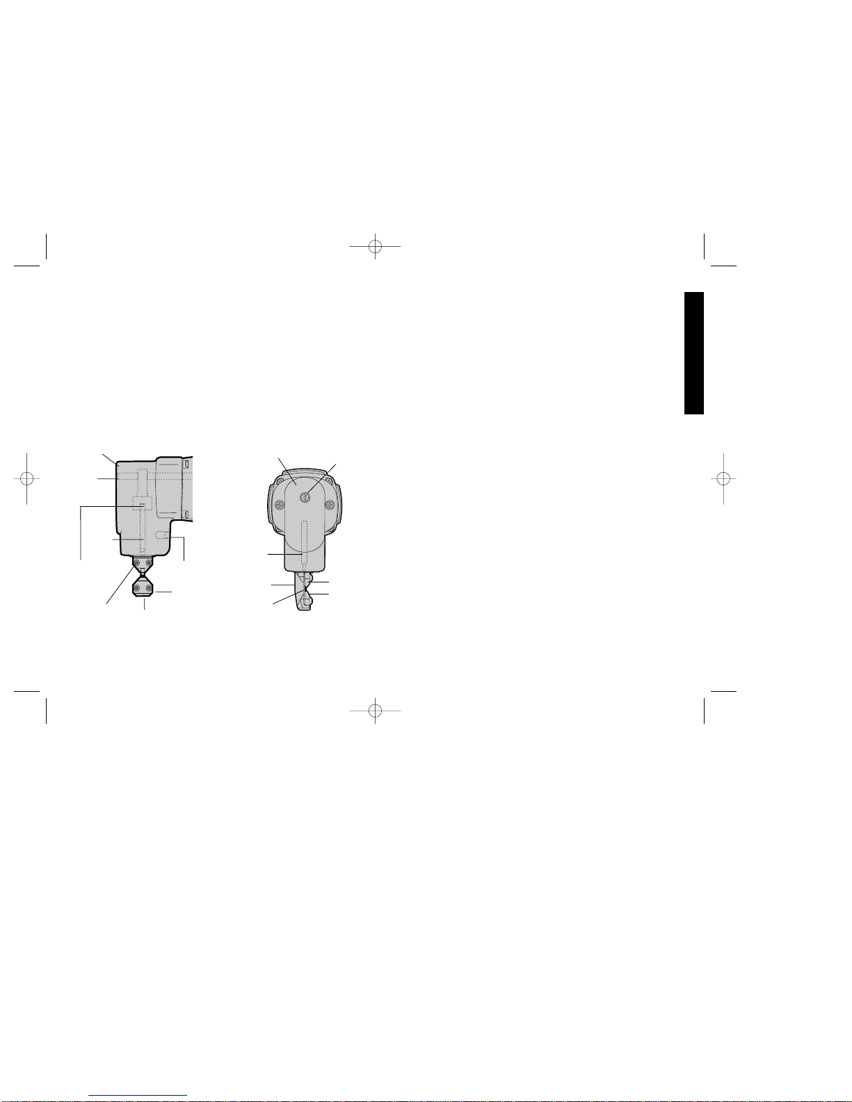
Figure 2
Figure 3
HEAD
CAM
SHAFT
PUNCH
SET
SCREW
SHOE
PUNCH
GUIDE
CONNECTING
ROD BUSHING
DIE
HEAD
PUNCH
SHOE
PUNCH
GUIDE
WEAR
PLATE
CAM
SHAFT
DIE
DW 897-220 5/2/02 1:48 PM Page 3
Page 7

4
the wear plate. If it is worn, replace it.
To remove the wear plate, dissassemble the punch guide and die
(Figure 3). Turn cam shaft with screwdriver so that punch is fully up.
Slide the wear plate from behind the punch. Insert a new wear plate.
Turn the cam shaft with screwdriver to move punch fully down.
Replace punch guide and die. Check punch engagement to die.
Adjust punch engagement, if necessary.
Maintenance
DISCONNECT TOOL FROM POWER SUPPLY BEFORE
PERFORMING ANY MAINTENANCE. Check that the punch and
die are sharp. If either is dull, sharpen or replace. Check wear plate
and replace if worn. Keep the tool clean. Blow off periodically. Never
use solvents or harsh chemicals for cleaning non-metallic parts of the
tool. Use a clean, dry rag only. Periodically dip the shoe in oil. This is
a precision tool. Use it carefully and store it in a protected place.
Cleaning & Lubrication
Use only mild soap and damp cloth to clean the tool. Never let any
liquid get inside the tool; never immerse any part of the tool into a
liquid.
Self-lubricating bearings are used in the tool and periodic
relubrication is not required. In the unlikely event that service is ever
needed, service center addresses are packed with your tool.
Motor Brushes
Brush replacement should be performed by authorized service
centers or other qualified service organizations.
Important
To assure product SAFETY and RELIABILITY, repairs, maintenance
and adjustment (including brush inspection and replacement) should
be performed by authorized service centers or other qualified service
organizations, always using identical replacement parts.
Full Warranty
DEWALT heavy duty industrial tools are warranted for one year from
date of purchase. We will repair, without charge, any defects due to
faulty materials or workmanship. For warranty repair information,
call 1-800-4-D
EWAL T. This warranty does not apply to accessories or
damage caused where repairs have been made or attempted by
others. This warranty gives you specific legal rights and you may
have other rights which vary in certain states or provinces.
In addition to the warranty, D
EWALT tools are covered by our:
30 DAY NO RISK SATISFACTION GUARANTEE
If you are not completely satisfied with the performance of your
DEWALTheavy duty industrial tool, simply return it to the participating
seller within 30 days for a full refund. Please return the complete unit,
transportation prepaid. Proof of purchase may be required.
English
DW 897-220 5/2/02 1:48 PM Page 4
Page 8

5
English
IMPORTANTES
MESURES DE SÉCURITÉ
(POUR TOUS LES OUTILS)
AVERTISSEMENT : Afin de réduire les risques d’incendie, de
secousses électriques ou de blessures lorsqu’on utilise des outils
électriques, il faut toujours respecter les mesures de sécurité
suivantes.
LIRE TOUTES LES DIRECTIVES.
• BIEN DÉGAGER LA SURFACE DE TRAVAIL. Des surfaces et
des établis encombrés peuvent être la cause de blessures.
• TENIR COMPTE DU MILIEU DE TRAVAIL. Protéger les outils
électriques de la pluie. Ne pas s’en servir dans des endroits
humides ou mouillés. Bien éclairer la surface de travail.
• SE PROTÉGER CONTRE LES SECOUSSES ÉLECTRIQUES.
Éviter tout contact avec des objets mis à la terre, comme des
tuyaux, radiateurs, cuisinières, réfrigérateurs et autres objets du
genre.
• ÉLOIGNER LES ENFANTS. Tous les visiteurs doivent être tenus
à l’écart de l’aire de travail et il faut les empêcher de toucher à
l’outil ou au cordon de rallonge.
• RANGER LES OUTILS INUTILISÉS. Il faut ranger les outils dans
un endroit sec, situé en hauteur ou fermé à clé, hors de la portée
des enfants.
• NE JAMAIS FORCER L’OUTIL. Afin d’obtenir un rendement sûr
et efficace, utiliser l’outil à son rendement nominal.
• UTILISER L’OUTIL APPROPRIÉ. Ne jamais exiger d’un petit outil
ou d’un accessoire le rendement d’un outil de fabrication plus
robuste. Se servir de l’outil selon l’usage prévu (par exemple, ne
pas se servir d’une scie circulaire pour couper des branches
d’arbres ou des bûches).
Grignoteuse de calibre 16
Modéle DW 897
INTERRUPTEUR
À BASCULEPADDLE
SWITCH
BOUTON DE
VERROUILLAG
E DE L´
INTERRUTEUR
BOÎTIER
TETE
ANNEAU DU
COUVERCLE
MATRICE
POINÇON
VIS DE BLOCAGE
POUR TOUT RENSEIGNEMENT SUPPLÉMENTAIRE SUR CET
OUTIL OU TOUT AUTRE OUTIL D
EWALT, COMPOSER SANS
FRAIS LE NUMÉRO:
1 800 4-DEWALT (1 800 433-9258)
Français
DW 897-220 5/2/02 1:48 PM Page 5
Page 9

6
English
• PORTER DES VÊTEMENTS APPROPRIÉS. Éviter de porter des
vêtements amples et des bijoux qui peuvent être happés par les
pièces en mouvement. Porter des gants de caoutchouc et des
chaussures à semelle antidérapante pour travailler à l’extérieur.
Protéger la chevelure si elle est longue.
• PORTER DES LUNETTES DE SÉCURITÉ. Porter également un
masque respiratoire si le travail de coupe produit de la poussière.
• NE PAS MANIPULER LE CORDON DE FAÇON ABUSIVE. Ne
pas transporter l’outil par le cordon ni tirer sur ce dernier pour le
débrancher de la prise. Éloigner le cordon des sources de chaleur,
des flaques d’huile et des arêtes tranchantes.
• ASSUJETTIR LA PIÈCE. Immobiliser la pièce à l’aide de brides
ou d’un étau. On peut alors se servir des deux mains pour faire
fonctionner l’outil, ce qui est plus sûr.
• NE PAS DÉPASSER SA PORTÉE. Toujours demeurer dans une
position stable et garder son équilibre.
• PRENDRE SOIN DES OUTILS. Conserver les outils propres pour
qu’ils donnent un rendement supérieur et sûr. Suivre les directives
concernant la lubrification et le remplacement des accessoires.
Inspecter régulièrement le cordon de l’outil et le faire réparer au
besoin à un atelier d’entretien autorisé. Inspecter régulièrement
les cordons de rallonge et les remplacer lorsqu’ils sont
endommagés. S’assurer que les poignées sont toujours propres,
sèches et libres de toute tache d’huile ou de graisse.
• DÉBRANCHER LES OUTILS NON UTILISÉS. Respecter cette
mesure lorsqu’on ne se sert pas de l’outil, ou qu’on doit le réparer
ou en changer un accessoire (comme une lame, un foret ou un
couteau).
• ENLEVER LES CLÉS DE RÉGLAGE. Prendre l’habitude de
vérifier si les clés de réglage ont été retirées avant de faire
démarrer l’outil.
• ÉVITER LES DÉMARRAGES ACCIDENTELS. Ne pas laisser le
doigt sur l’interrupteur lorsqu’on transporte l’outil. S’assurer que
l’interrupteur est à la position hors circuit lorsqu’on branche l’outil.
• CORDONS DE RALLONGE PRÉVUS POUR L’EXTÉRIEUR.
Lorsque l’outil est utilisé à l’extérieur, ne se servir que d’un cordon
de rallonge conçu pour l’extérieur et portant la mention appropriée.
On trouve de plus amples renseignements sur les cordons de
rallonge à la page 2.
• DEMEURER VIGILANT. Travailler avec vigilance et faire preuve
de bon sens. Ne pas se servir de l’outil lorsqu’on est fatigué.
• VÉRIFIER LES PIÈCES ENDOMMAGÉES. Vérifier l’alignement
et les attaches des pièces mobiles, le degré d’usure des pièces et
leur montage, ainsi que tout autre facteur susceptible de nuire au
bon fonctionnement de l’outil. Faire réparer ou remplacer tout
protecteur ou toute autre pièce endommagée dans un centre de
service autorisé, sauf si le présent guide fait mention d’un avis
contraire. Confier le remplacement de tout interrupteur défectueux
à un centre de service autorisé. Ne jamais se servir d’un outil
dont l’interrupteur est défectueux.
• NE PAS UTILISER les outils portatifs électriques dans des
endroits où l’atmosphère contient des vapeurs combustibles ou
explosives. Les étincelles que produit le moteur en marche
pourraient enflammer ces produits.
CONSERVER CES MESURES
À TITRE DE RÉFÉRENCE.
Mesures relatives aux grignoteuses
1. Toujours porter des lunettes de sécurité et des gants protecteurs.
2. Porter des chaussures de sécurité afin de protéger ses pieds des
débris métalliques tranchants sur le plancher.
3. Découper le matériau au plus au régime nominal de l’outil. Il faut
se rappeler que l’épaisseur du matériau est inversement
proportionnelle au calibre de l’outil (ainsi, un outil de calibre 14
coupe des matériaux plus épais qu’un outil de calibre 16). Un outil
de calibre 14 accepte un matériau d’une épaisseur de 1,90 mm
Français
DW 897-220 5/2/02 1:48 PM Page 6
Page 10

(0,075 po) et un outil de calibre 16, de 1,52 mm (0,060 po).
4. S’assurer que toutes les vis sont bien serrées. Les vérifier
régulièrement.
5. Débrancher l’outil avant de le régler.
6. Ne rien insérer dans les orifices du carter du moteur.
7. S’assurer que l’outil est toujours propre. En nettoyer les débris
métalliques et la poussière en y soufflant de l’air.
8. Bien fixer la pièce de métal à découper afin de l’empêcher de
bouger pendant les travaux.
INTERRUPTEUR À BASCULE
Pour mettre l’outil en marche, enfoncer l’interrupteur à bascule. Pour
l’arrêter, relâcher l’interrupteur à bascule. On peut verrouiller
l’interrupteur en mode de fonctionnement en enfonçant le bouton de
verrouillage qui se trouve près de l’arrière de l’outil tout en
maintenant enfoncé l’interrupteur à bascule. Toujours s’assurer que
7
Français
l’outil ne se trouve pas en mode de fonctionnement continu avant de
le brancher. Pour arrêter l’outil lorsque ce dernier est en mode de
fonctionnement continu, il suffit d’enfoncer et de relâcher
immédiatement l’interrupteur.
Fonctionnement
METTRE L’OUTIL HORS TENSION ET LE DÉBRANCHER AVANT
DE LE RÉGLER. Toujours porter des lunettes de sécurité et des
gants protecteurs.
Lubrifier la surface du matériau avec de l’huile. La grignoteuse est
conçue pour découper du métal plat et légèrement ondulé.
L’outil est monté en usine avec le poinçon en position avant pour
découper du métal plat et légèrement ondulé.
La tête de l’outil se place dans l’une de trois positions : vers la
gauche, vers l’avant et vers la droite (fig. 2). Pour faire tourner la tête,
desserrer la vis de blocage. Faire tourner la tête dans la position
voulue. NOTE: Ne pas faire tourner la tête sur elle-même au risque
de modifier l’insertion du poinçon dans la matrice.
Faire tourner le boîtier dans la tête et faire tourner la vis de blocage
jusqu’à ce que la vis s’installe dans le creux du patin. Bien serrer la
vis de blocage. Vérifier régulièrement si la vis est bien serrée.
La tête de la grignoteuse est conçue pour s’insérer dans un trou
d’un diamètre de 19 mm (3/4 po) afin de pouvoir découper au milieu
de la pièce. Le grignotage se fait dans un sens ou dans l’autre dans
le trou. Il y a un indicateur de la largeur du poinçon à l’avant du boîtier
permettant à l’utilisateur de pouvoir suivre une ligne (fig. 3).
Le dessous du boîtier comporte un guide pour gabarit de 13 mm
(0,51 po) de diamètre afin de pouvoir utiliser des gabarits.
L’épaisseur du gabarit et du matériau doit se situer entre 5 et 6,5mm
(13/64 po et 1/4 po). La forme du gabarit doit se trouver à 2,5 mm
(1 po) de la forme à grignoter. Il faut guider l’outil de sorte que le
diamètre extérieur (13 mm ou 0,51 po) du boîtier repose contre le
gabarit.
Figure 2
Figure 3
TÉTE
ARBRE
À
CAME
POINÇON
VIS DE
BLOCAGE
ANNEAU DU
COUVERCLE
BOÎTIER
GUIDE POUR
GABARIT
MATRICE
TÊTE
POINÇON
GUIDE POUR
GABARIT
ARBRE À
CAME
MATRICE
DOUILLE
DE LA BIELLE
DW 897-220 5/2/02 1:48 PM Page 7
Page 11

8
Remplacement du poinçon
Ne jamais utiliser un poinçon émoussé. On peut affûter les poinçons
jusqu’à une longueur minimale de 69 mm (2,72 po). Des poinçons
trop courts ne servent pas. Pour enlever le poinçon, desserrer la vis
de blocage de la tête d’environ 4 à 5 tours (fig. 2). Faire glisser le
boîtier hors de la tête. Dévisser le poinçon de la douille de la bielle.
Il faut affûter avec soin les poinçons à l’aide d’une meuleuse d’établi
munie d’une meule à fine granulosité. Ne pas trop raccourcir le
poinçon. Un poinçon trop court ne s’insère pas bien dans la matrice
et il faut le remplacer. La face meulée doit être perpendiculaire à l’axe
du poinçon. Après le meulage, ébarber soigneusement les rebords
affûtés. Ne pas en arrondir les coins.
Remontage de la tête de la grignoteuse
Visser le poinçon à fond dans la douille de la bielle. Faire glisser le
boîtier sur l’extrémité du poinçon et dans la tête. Faire tourner la tête
dans la position de coupe voulue. Bien serrer la vis de blocage.
Enfin, vérifier l’insertion du poinçon.
Vérification de l’insertion du poinçon
Puisque la longueur du poinçon est différente, il faut peut-être régler
l’insertion du poinçon. La vérifier en plaçant un tournevis à la me
plate dans la fente de l’arbre à came et en faisant tourner l’arbre
(fig. 2). Le poinçon devrait s’affaisser de 0,5 mm à 1,15 mm (de
0,02 po à 0,06 po) dans la matrice à la position la plus basse de la
course. Lorsque l’affaissement du poinçon dans la matrice est trop
grand, il en résulte une perte de rendement (le bout du poinçon ne se
dégage pas suffisamment de la matrice au plus haut de la course).
Réglage de l’insertion du poinçon
Lorsqu’il faut régler l’insertion du poinçon, desserrer la vis de blocage
et faire tourner le patin dans un sens horaire (le poinçon enfoncé
dans la matrice) ou dans le sens antihoraire (le poinçon hors de la
matrice). Bien serrer la vis de blocage. Faire tourner l’arbre à came à
l’aide du tournevis dans la fente afin de vérifier l’insertion du poinçon
(en abaissant complètement le poinçon). Répéter au besoin.
Remplacement de la matrice
Lorsque la matrice est émoussée, la remplacer. Remplacer
l’ancienne matrice en poussant l’anneau du couvercle vers le haut,
hors de la rainure. Se servir d’un poinçon de glissement pour faire
sortir la tige de retenue du dessous de l’anneau du couvercle. Retirer
la matrice de l’arbre-porteur. Installer une nouvelle matrice sur
l’arbre-porteur. Aligner le trou de la matrice sur la rainure de l’arbreporteur. Installer la tige. Enclencher l’anneau du couvercle dans la
rainure du dessus de la matrice.
Entretien
DÉBRANCHER L’OUTIL AVANT D’EFFECTUER TOUT TRAVAIL
D’ENTRETIEN. S’assurer que le poinçon et la matrice sont affûtés.
Lorsque l’un d’eux est émoussé, l’affûter ou le remplacer. S’assurer
que l’outil est propre. Utiliser régulièrement de l’air pour en souffler
les saletés. Ne jamais se servir de solvants ni de produits chimiques
puissants pour nettoyer les composants non métalliques de l’outil.
Utiliser seulement un chiffon propre et sec. Tremper régulièrement le
patin dans de l’huile. Il s’agit d’un outil de précision. S’en servir avec
soin et le ranger dans un endroit protégé.
Nettoyage et lubrification
Nettoyer l’outil seulement à l’aide d’un savon doux et d’un linge
humide. Ne laisser aucun liquide s’infiltrer dans l’outil et ne jamais
immerger l’outil.
L’outil est monté sur des roulements autolubrifiants qui ne requièrent
pas de lubrification périodique. Dans le cas peu probable où l’outil
nécessiterait de l’entretien, la liste des centres de service se trouve
dans l’emballage.
Français
DW 897-220 5/2/02 1:48 PM Page 8
Page 12

Balais du moteur
Il faut confier le remplacement des balais au personnel d’un centre
de service autorisé.
Important
Pour assurer la SÉCURITÉ D’EMPLOI et la FIABILITÉ de l’outil, n’en
confier la réparation, l’entretien et les rajustements (y compris
l’inspection et le remplacement des balais) qu’au personnel d’un
centre de service D
EWALT ou d’un atelier d’entretien autorisé
n’utilisant que des pièces de rechange identiques.
Accessoires
Les accessoires recommandés pour cet outil sont vendus chez les
détaillants ou au centre de service de la région. Pour trouver un
accessoire, communiquer avec le détaillant ou le centre de service
de la région.
MISE EN GARDE: L’utilisation de tout autre accessoire non
recommandé pour l’outil peut être dangereuse.
Garantie complète
Les outils industriels de service intensif DEWALT sont garantis
pendant un an à partir de la date d’achat. Toute pièce d’un outil
D
EWALT qui s’avérait défectueuse en raison d’un vice de matière ou
de fabrication sera réparée ou remplacée sans frais. Pour obtenir de
plus amples renseignements sur les réparations couvertes par la
garantie, composer le 1 (800) 4-D
EWALT (! (800) 433-9258). La ga
rantie ne couvre pas les accessories ni les réparations tentées ou
effectuées par des tiers. Les modalités de la présente garantie
donnent des droits légaux spécifiques. L’utilisateur peut également
se prévaloir d’autres droits selon l’état ou la province qu’il habite.
En outre, la garantie suivante couvre les outils D
EWALT.
GARANTIE DE SATISFACTION DE 30 JOURS OU ARGENT REMIS
Si, pour quelque raison que ce soit, l’outil industriel de service intensif
D
EWALT ne donne pas entière satisfaction, il suffit de le retourner
chez le marchand participant dans les 30 jours suivant la date
d’achat afin d’obtenir un remboursement complet. Il faut retourner,
port payé, l’outil complet. On peut exiger une preuve d’achat.
9
Français
Imported by / Importé par
D
EWALT Canada Inc.
100 Central Ave.
Brockville (Ontario) K6V 5W6
Voir la rubrique “Outils électriques”
des Pages Jaunes
pour le service et les ventes.
DW 897-220 5/2/02 1:48 PM Page 9
Page 13

Instrucciones importantes de seguridad
ADVERTENCIA: Es indispensable sujetarse a las precauciones
básicas de seguridad, con la finalidad de reducir el peligro de
incendio, choque eléctrico y lesiones personales, en todas las
ocasiones en que se utilicen herramientas eléctricas. Entre estas
precauciones se incluyen la siguientes:
LEA TODAS LAS INSTRUCCIONES
Doble aislamiento
Las herramientas DOBLEMENTE aisladas se han elaborado de
manera integral con dos capas separadas de aislamiento eléctrico o
una capa doble de aislamiento entre usted y el sistema eléctrico
que contienen. Las herramientas construidas con este sistema de
aislamiento no requieren conectarse a tierra. Como resultado su
herramienta está equipada con una clavija de dos patas que le
permite emplear cordones de extensión sin preocuparse por tener
una conexión a tierra.
NOTA: El doble aislamiento no substituye a las precauciones
normales de seguridad cuando se opera esta herramienta. La
finalidad de este sistema de aislamiento es ofrecer a usted
protección añadida contra lesiones resultantes de fallas en el
aislamiento eléctrico interno de la herramienta.
PRECAUCION: UTILICE SOLAMENTE REFACCIONES ORIGINALES CUANDO HAGA SERVICIO a cualquier herramienta.
Repare o reemplace los cordones eléctricos dañados.
Clavijas polarizadas
Se emplean clavijas polarizadas (con una pata más ancha que la
otra) para reducir los riesgos de choque eléctrico. Cuando el cordón
eléctrico cuente con este tipo de clavija, ajustará en un contacto
polarizado solamente de una manera. Si la clavija no ajusta
10
Español
Epecificaciones (DW897)
Tensión de alimentación 120 V
Potencia nominal: 225 W
Frecuencia de operación:60 Hz
Consumo de corriente: 6,5 A
DW 898
Cortadoras de lámina
Calibre 16
INTERRUPTOR DE
PALETA
BOTON DE
ENCENDIDO
PERMANENTE
CARCAZA
CABEZA
ARILLO DE
CUBIERTA
DADO
PUNZON
PRISIONERO
DW 897-220 5/2/02 1:48 PM Page 10
Page 14

completamente en su contacto, inviértala. Si aún así no ajusta, llame
a un electricista calificado para que le instale un contacto polarizado
apropiado. No modifique o haga cambios en la clavija por ningún
motivo.
Instrucciones de seguridad para todas
las herramientas
• CONSERVE LIMPIA LA ZONA DE TRABAJO. Las superficies y
los bancos con objetos acumulados en desorden propician los
accidentes.
• OTORGUE PRIORIDAD A LA ZONA DE TRABAJO. No deje las
herramientas eléctricas expuestas a la lluvia. No las utilice en
lugares inundados o mojados. Conserve bien iluminada la zona de
trabajo. No utilice la herramienta en presencia de líquidos o gases
inflamables.
• PROTEJASE CONTRA EL CHOQUE ELECTRICO. Evite el
contacto corporal con superficies aterrizadas, por ejemplo,
tuberías, radiadores, antenas y gabinetes de refrigeración.
• CONSERVE APARTADOS A LOS NIÑOS. No permita que los
visitantes toquen las herramientas o los cables de extensión.
Todos los visitantes deben estar alejados de la zona de trabajo.
• GUARDE LAS HERRAMIENTAS QUE NO EMPLEE. Las
herramientas que no se utilizan deben guardarse en un lugar seco
y elevado o bajo llave — fuera del alcance de los niños.
• NO FUERCE LA HERRAMIENTA.Esta cumplirá su función mejor
y con más seguridad a la velocidad y la presión para las que se
diseñó.
• EMPLEE LA HERRAMIENTA ADECUADA. No fuerce a una
herramienta pequeña o a sus dispositivos de montaje en un
trabajo de tipo pesado. No emplee la herramienta en una tarea
para la que no se diseñó.
• VISTASE DE LA MANERA ADECUADA.No use ropas o artículos
de joyería flojos, pues podrían quedar atrapados por las partes
móviles de las herramientas. Se recomienda el empleo de guantes
11
Español
de caucho y calzado antiderrapante cuando se trabaje al aire libre.
Cúbrase bien la cabeza para sujetarse el cabello si lo tiene largo.
• COLOQUESE ANTEOJOS DE SEGURIDAD. Póngase también
una mascarilla contra el polvo si lo produce la operación que va a
efectuar.
• TENGA CUIDADO CON EL CORDON ELECTRICO. Nunca
levante la herramienta tomándola por el cordón, ni tire de éste para
desconectarlo del enchufe. Apártelo del calor y los objetos
calientes, las substancias grasosas y los bordes cortantes.
• ASEGURE LOS OBJETOS SOBRE LOS QUE TRABAJE. Utilice
prensas o tornillos de banco para sujetar los objetos sobre los
que va a trabajar. Esto ofrece mayor seguridad que sujetar los
objetos con la mano, y además deja libres ambas manos para
operar la herramienta.
• CONSERVE EL EQUILIBRIO. Conserve en todo momento bien
apoyados los pies, lo mismo que el equilibrio.
• CUIDE SUS HERRAMIENTAS. Conserve sus herramientas
afiladas y limpias para que funcionen mejor y con mayor
seguridad. Siga las instrucciones para lubricación y cambio de
accesorios de su unidad. Revise periódicamente el cordón
eléctrico y hágalo reparar o reemplazar por un centro de servicio si
está dañado. Cambie los cordones de extensión si están dañados.
Conserve las empuñaduras secas, limpias y libres de aceite y
grasa.
• DESCONECTE Y APAGUE LAS HERRAMIENTAS cuando no las
use, antes de darles servicio y cuando cambie accesorios, tales
como discos, brocas y otros dispositivos de corte.
• RETIRE LAS LLAVES DE AJUSTE Y DE TUERCAS. Adquiera
el hábito de asegurarse que se han retirado las llaves de ajuste
de las herramientas antes de accionarlas.
• EVITE QUE LA HERRAMIENTA SE ACCIONE ACCIDENT-
ALMENTE. Nunca sostenga una herramienta que está conectada
con el dedo en el interruptor. Asegúrese que el interruptor está en
posición de “apagado” antes de conectar la unidad.
DW 897-220 5/2/02 1:48 PM Page 11
Page 15

que se encuentren dañadas deberán cambiarse o repararse en un
centro de servicio autorizado, a menos que se diga otra cosa en
el manual del usuario. Haga que se cambien los interruptores
dañados en un centro de servicio autorizado. No emplee ninguna
herramienta que tenga estropeado o inutilizado el interruptor.
Reglas de operación para cortadoras de
lámina
1. Utilice siempre anteojos de seguridad así como guantes
protectores.
2. Use calzado de seguridad para proteger sus pies de rebabas
metálicas afiladas que pudieran caer al suelo.
3. Corte material hasta o por debajo de la capacidad especificada.
Recuerde que el espesor del material aumenta mientras que el
12
• CORDONES DE EXTENSION. Asegúrese que su cordón de
extensión esté en buenas condiciones. Cuando utilice un cordón
de extensión, asegúrese que tenga el calibre suficiente para
soportar la corriente necesaria para su herramienta. Un cordón
eléctrico con calibre insuficiente causará una caída en el voltaje de
la línea, resultando en pérdida de potencia y sobrecalentamiento.
La tabla siguiente ilustra el calibre correcto que debe utilizarse de
conformidad con la longitud del cordón y el amperaje descrito por
la placa de identificación. Si tiene alguna duda, utilice el cable con
el calibre siguiente (mayor). Mientras más chico sea el número,
mayor será su calibre.
Calibre mínimo para cordones de extensión
VoltsLongitud total del cordón en metro
120V 0-7.62 7.63-15.24 15.25-30.48 30.49-45.72
240V 0-15.24 15.25-30.48 30.49-60.96 60.97-91.44
AMPERAJE
Más No más Calbre del cordón
de de
0 - 6 18 16 1614
6 - 10 18 16 1412
10 - 12 16 16 14
1212 - 16 14 12 No Recomendado
• CORDONES DE EXTENSION PARA INTEMPERIE. Cuando
opere su herramienta a la intemperie, utilice únicamente cordones
de extensión diseñados y marcados para este fin.
• NO SE DISTRAIGA. Concéntrese en lo que está haciendo.
Recurra al sentido común. No opere ninguna herramienta si está
fatigado.
• VERIFIQUE LAS PARTES DAÑADAS. Antes de seguir
empleando cualquier herramienta, es indispensable verificar con
mucho cuidado que las guardas u otras partes dañadas puedan
operar de la manera adecuada para cumplir con su función.
Verifique la alineación de las partes móviles, la firmeza con que
deben encontrarse sujetas a sus montaduras, las partes rotas, las
propias montaduras y cualesquiera otros detalles que pudieran
afectar la operación de la herramienta. Las guardas y otras partes
Español
Figura 2
Figura 3
CABEZA
ARBOL
DE
LEVAS
PUNZON
PRISIONERO
ZAPATA
GUIA DE
PUNZON
BUJE DE
VARILLA DE
CONEXION
DADO
CABEZA
PUNZON
ZAPATA
GUIA DE
PUNZON
PLACA DE
DESGASTE
ARBOL
DE LEVAS
DADO
DW 897-220 5/2/02 1:48 PM Page 12
Page 16

número de calibre disminuye (el calibre 14 tiene mayor espesor
que el calibre 16). El espesor del calibre 14 es de 1,90 mm
(0,075”); el espesor del calibre 16 es de 1,52 mm (0,060”).
4. Conserve apretados todos los tornillos. Revise periódicamente
que no se hayan aflojado.
5. Desconecte la herramienta antes de efectuar cualquier ajuste.
6. No ponga nada dentro de la abertura de la carcaza del motor.
7. Conserve limpia la herramienta. Sopletee cualquier residuo
metálico de la herramienta, así como la mugre.
8. Asegure con firmeza la pieza de metal que vaya a cortar para
evitar movimientos durante la operación.
Interruptor de paleta
Oprima el interruptor de paleta para encender la unidad. Para
apagarla, libere el interruptor. El interruptor puede asegurarse para
operación continua accionando el botón que se encuentra cerca de
la parte posterior de la herramienta al mismo tiempo que se oprime
la paleta. Asegúrese siempre que la herramienta no esté en posición
de encendido permanente antes de conectarla. Para apagar la
herramienta cuando el interruptor se encuentra en esta posición,
oprima y libere la paleta una vez.
Operación
APAGUE Y DESCONECTE LA HERRAMIENTA DE LA TOMA DE
CORRIENTE ANTES DE HACER CUALQUIER AJUSTE. Utilice
siempre gafas de seguridad y guantes protectores.
Lubrique la superficie del material con aceite. La cortadora está
diseñada para trabajar con metal plano y corrugado con poca
profundidad.
La herramienta se ensambla en la fábrica con el punzón orientado
hacia adelante para cortar metal plano y corrugado con poca
profundidad.
La cabeza puede alinearse en tres posiciones: a la izquierda, hacia
13
Español
adelante y a la derecha (observe la figura 2). Afloje el prisionero para
girar la cabeza. Gire la cabeza hacia la dirección que desee.NOTA:
No gire la cabeza en un círculo completo ya que esto cambiará la
alineación del punzón y el dado.
Gire la carcaza de la cabeza y atornille el prisionero hasta sentir
que se acomoda en una cavidad en la zapata. Apriete el prisionero
con firmeza. Revise periódicamente que este tornillo esté apretado.
La cabeza de la cortadora está diseñada para acoplarse a través de
un orificio de 19 mm (3/4”) para iniciar un corte a la mitad de una
pieza. El corte se puede hacer en cualquier dirección a partir de
este orificio. Al frente de la carcaza se encuentra un indicador de
ancho de punzón que permite que el usuario siga una línea de cerca
(figura 3).
La parte inferior de la carcaza tiene una guía de 13 mm (0,51”) de
diámetro que le permite el empleo de plantillas. El espesor de la
plantilla debe ser tal que el espesor total de ésta junto con la pieza
de trabajo sea de 5 a 6,5 mm (13/64” a 1/”). El contorno de la plantilla
debe estar a 2,5 mm (0,1”) del contorno por recortar. Debe guiarse la
herramienta de manera que el diámetro exterior de la carcaza (13
mm o 0,51”) descanse en la plantilla.
Cambio de punzones
Nunca corte con un punzón sin filo. Los punzones pueden afilarse
hasta que lleguen a una longitud de 69 mm (2,72”). Cuando son más
cortos son inútiles. Para sacar el punzón, afloje el prisionero
aproximadamente de 4 a 5 vueltas (observe la figura 2). Deslice la
carcaza de la cabeza. Destornille el punzón del buje conector de
varilla. El punzón puede afilarse con cuidado en un esmeril de banco
con piedra de grano fino. T enga cuidado de no permitir que el punzón
llegue a una longitud menor a la mínima. Los punzones más cortos
no alcanzarán debidamente el dado y deberán reemplazarse. La
cara del esmeril deberá estar a escuadra con el eje del punzón.
Después de esmerilar, asiente cuidadosamente los filos para
eliminar rebabas. No redondee las esquinas.
DW 897-220 5/2/02 1:48 PM Page 13
Page 17

orificio en cruz del dado con el canal del eje transportador. Instale el
perno. Coloque el arillo sobre el dado en el canal hecho para este fin.
Mantenimiento
Utilice únicamente un jabón suave y un trapo húmedo para limpiar
la herramienta. Nunca permita que se introduzca ningún líquido en la
herramienta, ni sumerja ninguna parte de ésta en ningún líquido.
Se han empleado baleros auto lubricantes en la fabricación de esta
herramienta y no se requiere de lubricación periódica. En el
improbable caso que su herramienta llegase a requerir servicio,
llévela a un centro de servicio autorizado.
Accesorios
Dispone usted de los accesorios para su herramienta por un cargo
adicional con su distribuidor local autorizado.
EL ACCESORIO DEBE ESTAR CLASIFICADO PARA UTILIZARSE
A UNA VELOCIDAD IGUAL O MAYOR QUE LAS R.P.M.
SEÑALADAS EN LA PLACA DE IDENTIFICACION DE LA
HERRAMIENTA QUE SE ESTE EMPLEANDO.
Si necesita ayuda para encontrar cualquier accesorio, por favor
comuníquese al 326-7100.
PRECAUCION: El empleo de cualquier otro accesorio no
recomendado para utilizarse con esta herramienta puede ser
peligroso.
Importante
Para garantizar la SEGURIDAD y la CONFIABILIDAD del producto,
deberán hacerse reparaciones, mantenimiento y ajustes (incluyendo
revisión y cambio de los carbones) por centros autorizados de
servicio u otras organizaciones calificadas que empleen siempre
refacciones idénticas
14
Ensamblaje de la cabeza de la cortadora
Atornille el punzón completamente dentro del buje de conexión de
varilla. Deslice la carcaza sobre el extremo del punzón y hacia dentro
de la cabeza. Gire la cabeza hacia la orientación de corte que desee.
Apriete el prisionero y a continuación, revise el acoplamiento del
punzón con el dado.
Revisión del acoplamiento del punzón
Ya que la longitud del punzón ha cambiado, puede requerirse ajustar
el acoplamiento. Revise el acoplamiento del punzón colocando un
destornillador de punta plana en la ranura del eje de la leva (observe
la figura 2). El punzón debe penetrar de 0,5 a 1,15 mm (0,2” a 0,6”)
dentro del dado en la posición de desplazamiento completo.
Demasiada penetración en el dado puede originar pérdida de
capacidad (la parte inferior del punzón no despejará suficientemente
el dado en la carrera hacia arriba).
Ajuste del acoplamiento del punzón
Si el acoplamiento del punzón requiere ajustarse, afloje el prisionero
y gire la zapata en el sentido de las manecillas del reloj (mayor
penetración en el dado) o en sentido contrario a las manecillas del
reloj (hacia fuera del dado). Apriete el prisionero con firmeza. Gire el
eje de la leva con un destornillador en la ranura para verificar la
penetración del punzón (moviendo el punzón completamente hacia
abajo). Repita cuanto sea necesario.
Cambio del dado
Si el dado llega a estar romo, reemplácelo. Cambie el dado viejo
empujado el arillo de la cubierta hacia arriba y hacia afuera del canal
del dado. Retire el perno retén de debajo del arillo de la cubierta con
un martillo punzón. Tire del dado hacia fuera del eje transportador.
Instale un dado nuevo en el eje transportador. Haga coincidir el
Español
DW 897-220 5/2/02 1:48 PM Page 14
Page 18

PARA REPARACION Y SERVICIO DE SUS HERRAMIENTAS
ELECTRICAS FAVOR DE DIRIGIRSE AL CENTRO DE SERVICIO MAS
CERCANO
CULIACAN
Av. Nicolas Bravo #1063 Sur (91 671) 242 10
GAUDALAJARA
Av. La Paz #1779 (91 3) 826 69 78.
MEXICO
Eje Lázaro Cárdenas No. 18 Local D, Col. Obrera 588-9377
MERIDA
Calle 63 #459-A (91 99) 23 54 90
MONTERREY
Av. Francisco I. Madero Pte. 1820-A (91 83) 72 11 25
PUEBLA
17 Norte #205 (91 22) 46 37 14
QUERETARO
Av. Madero 139 Pte. (91 42) 14 16 60
SAN LOUIS POTOSI
Pedro Moreno #100 Centro (91 48) 14 25 67
TORREON
Blvd. Independencia, 96 pte. (91 17) 16 52 65
VERACRUZ
Prolongación Diaz Miron #4280 (91 29) 21 70 16
VILLAHERMOSA
Constitucion 516-A (91 93) 12 53 17
PARA OTRAS LOCALIDADES LLAME AL: 326 7100
15
Español
Garantía Completa
Las herramientas industriales DEWALT están garantizadas durante un año a
partir de la fecha de compra. Repararemos, sin cargos, cualquier falla debida
a material o mano de obra defectuosos. Por favor regrese la unidad completa,
con el transporte pagado, a cualquier Centro de Servicio para Herramientas
Industriales de D
EWALT o a las estaciones de servicio autorizado enlistadas
bajo "Herramientas Eléctricas" en la Sección Amarilla. Esta garantía no se
aplica a los accesorios ni a daños causados por reparaciones efectuadas
por terceras personas. Esta garantía le otorga derechos legales específicos,
y usted puede tener otros derechos que pueden variar de estado a estado.
En adición a la garantía, las herramientas D
EWALT están amparadas por
nuestra:
GARANTÍA DE SATISFACCIÓN SIN RIESGO POR 30 DÍAS
Si usted no se encuentra completamente satisfecho con el desempeño de
su herramienta industrial DEWALT, sencillamente devuélvala a los
vendedores participantes durante los primeros 30 días después de la fecha
de compra para que le efectúen un reembolso completo. Por favor regrese
la unidad completa, con el transporte pagado. Se puede requerir prueba de
compra.
IMPORTADO: DEWALT S.A. DE C.V.
BOSQUES DE CIDROS ACCESO RADIATAS NO. 42
COL. BOSQUES DE LAS LOMAS.
05120 MÉXICO, D.F
TEL. 326-7100
SECCI N
AMARILLA
Si funciona…
y funciona muy bien.
Para servicio y ventas consulte
“HERRAMIENTAS ELECTRICAS”
en la sección amarilla.
DW 897-220 5/2/02 1:48 PM Page 15
 Loading...