

Page 1

DEWALT Industrial Tool Co., 701 East Joppa Road, Baltimore, MD 21286 Printed in U.S.A. (JUN00-CD-1) Form No. 384122
DW890, DW891, DW891-220 Copyright © 1997, 2000
DW890/384122 9/1/00 3:24 PM Page 2
Page 2

INSTRUCTION MANUAL
GUIDE D'UTILISATION
MANUAL DE INSTRUCCIONES
DW890, DW891, DW891-220
Swivel Head Shears
Cisaille à tête pivotante
Cizalla con cabeza giratoria
INSTRUCTIVO DE OPERACIÓN, CENTROS DE SERVICIO Y PÓLIZA
DE GARANTÍA. ADVERTENCIA: LÉASE ESTE INSTRUCTIVO ANTES
DE USAR EL PRODUCTO.
DW890/384122 9/1/00 3:24 PM Page 3
Page 3
Important Safety Instructions
WARNING: When using electric tools, basic safety precautions
should always be followed to reduce risk of fire, electric shock, and
personal injury, including the following:
READ ALL INSTRUCTIONS
Double Insulation
Double insulated tools are constructed throughout with two separate
layers of electrical insulation or one double thickness of insulation
between you and the tool’s electrical system. Tools built with this
insulation system are not intended to be grounded. As a result, your
tool is equipped with a two prong plug which permits you to use
extension cords without concern for maintaining a ground
connection.
NOTE: Double insulation does not take the place of normal safety
precautions when operating this tool. The insulation system is for
added protection against injury resulting from a possible electrical
insulation failure within the tool.
CAUTION: WHEN SERVICING USE ONLY IDENTICAL REPLACEMENT PARTS. Repair or replace damaged cords.
Polarized Plugs(DW890, DW891)
Polarized plugs (one blade is wider than the other) are used on
equipment to reduce the risk of electric shock. When provided, this
plug will fit into a polarized outlet only one way. If the plug does not
fit fully into the outlet, reverse the plug. If it still does not fit, contact a
qualified electrician to install the proper outlet. Do not change the
plug in any way.
Safety Instructions For All Tools
• KEEP WORK AREA CLEAN. Cluttered areas and benches invite
injuries.
• CONSIDER WORK AREA ENVIRONMENT. Don’t expose power
English
IF YOU HAVE ANY QUESTIONS OR COMMENTS ABOUT THIS
OR ANY D
EWALT TOOL, CALL US TOLL FREE AT:
1-800-4-DEWALT (1-800-433-9258)
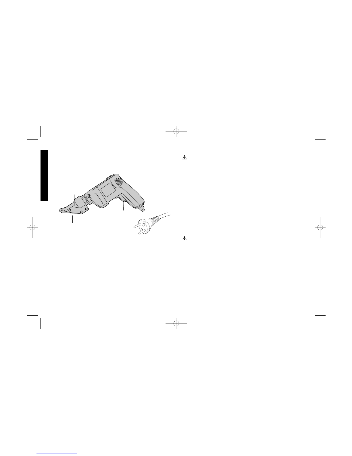
SWIVEL
HEAD
BLADE
DW891-200
TRIGGER
SWITCH
DEWALT... BUILT JOBSITE TOUGH
DeWalt high performance industrial tools are made for America’s
toughest industrial and construction applications. The design of every
tool in the line—from drills to sanders to grinders—is the result of
rigorous use on jobsites and throughout industry. Each tool is
produced with painstaking precision using advanced manufacturing
systems and intense quality control. Every tool is checked before it
leaves the factory to make sure that it meets your standards for
durability, reliability and power.
D
EWALT Built Jobsite Tough…WE GUARANTEE IT.
DW890/384122 9/1/00 3:24 PM Page 4
Page 4

tools to rain. Don’t use power tools in damp or wet locations. Keep
work area well lit. Do not use tool in presence of flammable liquids
or gases.
• GUARD AGAINST ELECTRIC SHOCK. Prevent body contact
with grounded surfaces. For example; pipes, radiators, ranges, and
refrigerator enclosures.
• KEEP CHILDREN AWAY. Do not let visitors contact tool or
extension cord. All visitors should be kept away from work area.
• STORE IDLE TOOLS. When not in use, tools should be stored in
dry, and high or locked-up place — out of reach of children.
• DON’T FORCE TOOL. It will do the job better and safer at the
rate for which it was intended.
• USE RIGHT TOOL. Don’t force small tool or attachment to do the
job of a heavy-duty tool. Don’t use tool for purpose not intended.
• DRESS PROPERLY. Do not wear loose clothing or jewelry. They
can be caught in moving parts. Rubber gloves and non-skid
footwear are recommended when working outdoors. Wear
protective hair covering to contain long hair.
• USE SAFETY GLASSES. Also use face or dust mask if operation
is dusty.
• DON’T ABUSE CORD. Never carry tool by cord or yank it to
disconnect from receptacle. Keep cord from heat, oil, and sharp
edges.
• SECURE WORK. Use clamps or a vise to hold work. It’s safer than
using your hand and it frees both hands to operate tool.
• DON’T OVERREACH. Keep proper footing and balance at all
times.
• MAINTAIN TOOLS WITH CARE. Keep tools sharp and clean for
better and safer performance. Follow instructions for lubricating
and changing accessories. Inspect tool cords periodically and if
damaged, have repaired by authorized service facility. Inspect
extension cords periodically and replace if damaged. Keep
handles dry, clean, and free from oil and grease.
• DISCONNECT OR LOCK OFF TOOLS when not in use, before
servicing, and when changing accessories, such as blades, bits,
cutters.
• REMOVE ADJUSTING KEYS AND WRENCHES. Form habit of
checking to see that keys and adjusting wrenches are removed
from tool before turning it on.
• AVOID UNINTENTIONAL STARTING. Don’t carry tool with finger
on switch. Be sure switch is off when plugging in.
• EXTENSION CORDS. Make sure your extension cord is in good
condition. When using an extension cord, be sure to use one
heavy enough to carry the current your product will draw. An
undersized cord will cause a drop in line voltage resulting in loss
of power and overheating. The following table shows the correct
size to use depending on cord length and nameplate ampere
rating. If in doubt, use the next heavier gage. The smaller the gage
number, the heavier the cord.
Recommended Minimum Wire Size for Extension Cords
Total Length of Cord
25 ft. 50 ft. 75 ft. 100 ft. 125 ft. 150 ft. 175 ft.
7.6 m 15.2 m 22.9 m 30.5 m 38.1 m 45.7 m 53.3 m
Wire Size
18 AWG 18 AWG 16 AWG 16 AWG 14 AWG 14 AWG 12 AWG
• OUTDOOR USE EXTENSION CORDS. When tool is used
outdoors, use only extension cords intended for use outdoors and
so marked.
• STAY ALERT. Watch what you are doing. Use common sense.
Do not operate tool when you are tired.
• CHECK DAMAGED PARTS. Before further use of the tool, a
guard or other part that is damaged should be carefully checked
to determine that it will operate properly and perform its intended
function. Check for alignment of moving parts, binding of moving
parts, breakage of parts, mounting, and any other conditions that
may affect its operation. A guard or other part that is damaged
1
English
DW890/384122 9/1/00 3:24 PM Page 1
Page 5
2
should be properly repaired or replaced by an authorized service
center unless otherwise indicated elsewhere in this instruction
manual. Have defective switches replaced by authorized service
center. Do not use tool if switch does not turn it on and off.
• CAUTION: When cutting into walls, floors or wherever live
electrical wires may be encountered, DO NOT TOUCH ANY
METAL PARTS OF THE TOOL! Hold the tool only by insulated
grasping surfaces to prevent electric shock if you saw into a live
wire.
WARNING: Some dust created by power sanding, sawing, grinding,
drilling, and other construction activities contains chemicals known to
cause cancer, birth defects or other reproductive harm. Some
examples of these chemicals are:
• lead from lead-based paints,
• crystalline silica from bricks and cement and other masonry
products, and
• arsenic and chromium from chemically-treated lumber (CCA).
Your risk from these exposures varies, depending on how often you do
this type of work. To reduce your exposure to these chemicals: work in
a well ventilated area, and work with approved safety equipment, such
as those dust masks that are specially designed to filter out
microscopic particles.
SAVE THESE INSTRUCTIONS
Motor
Your DEW ALT tool is powered by a DEWALT built motor . Be sure your
power supply agrees with the nameplate marking. Voltage decrease
of more than 10% will cause loss of power and overheating. All
D
EWALT tools are factory tested; if this tool does not operate, check
the power supply. If the nameplate marking on the tool shows 120
volts, 60Hz or “AC Only”,(DW890, DW891) your tool must be
operated only with alternateing current and never with direct current.
A marking of 220/240 volts, 50-60 Hz or “AC Only” (DW891-220)
English
FIG. 1
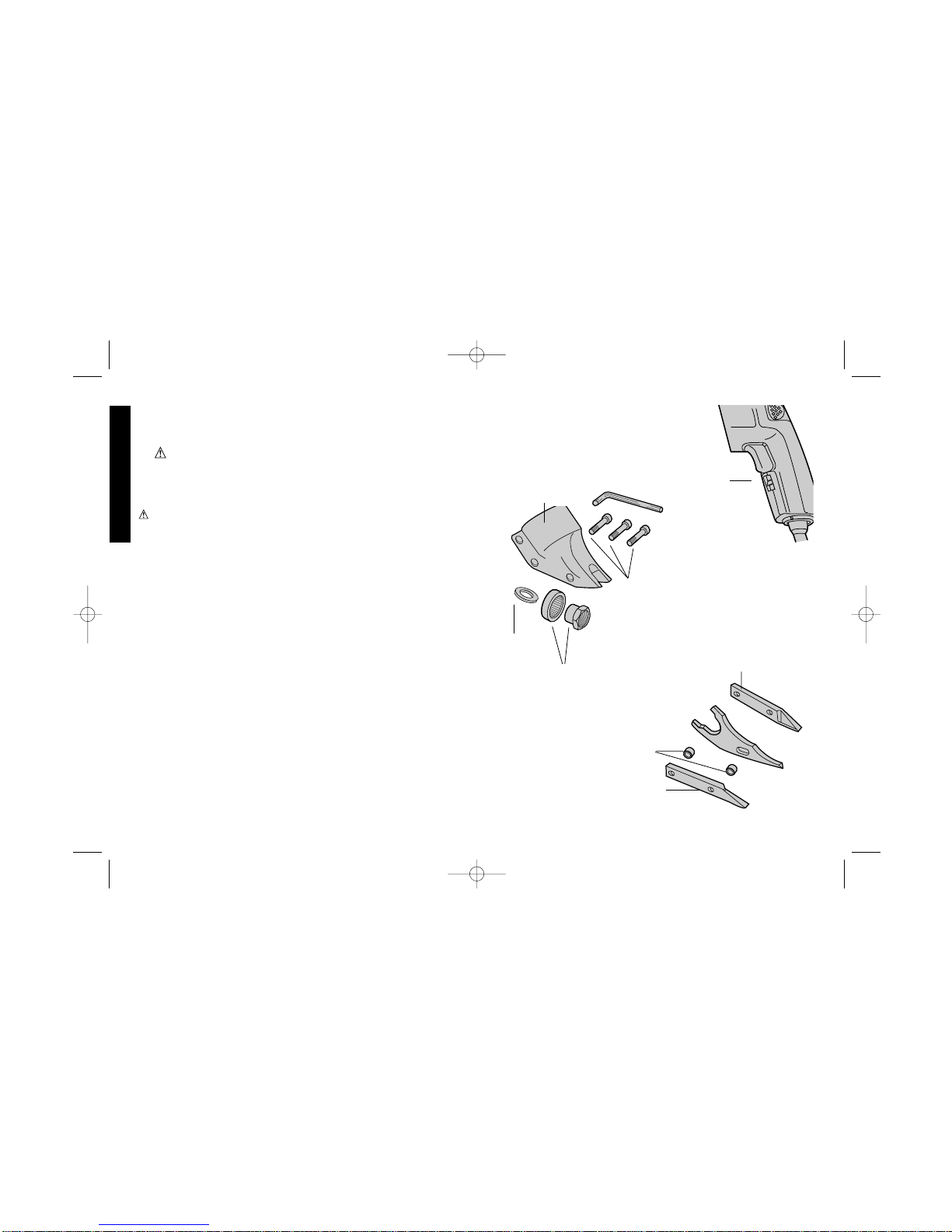
LOCK
BUTTON
FIG. 2
CAP
SCREWS
HOUSING
ECCENTRIC
BEARING
ASSEMBLY
WASHER
FIG. 3
SIDE KNIFE AND
SIDE SPACER
SPACER
BUSHINGS
LEFT SIDE KNIFE
DW890/384122 9/1/00 3:24 PM Page 2
Page 6
means your tool must be operated with alternating current never
with direct current.
Switch
To start tool, depress trigger switch. To stop tool, release the trigger.
To lock the trigger in the on position for continuous operation,
depress trigger, push up the lock button (Figure 1), and gently
release the trigger. To release the locking mechanism, depress the
trigger fully, then release it. Before using the tool each time, be sure
that the lock button release mechanism is working freely. Be sure to
release the switch lock button before disconnecting the plug from
the power supply. Failure to do so will cause the tool to start
immediately the next time it is plugged in. Damage or injury could
result. The variable speed trigger switch permits speed control.
The farther the trigger is depressed, the higher the speed of the
shear.
Disassembly and Assembly (Figures 2
and 3)
To remove shear head from motor, loosen 3 cap screws. Remove
shear head by pulling head firmly forward. Slight twisting action may
be required if head does not slide off easily.
3
English
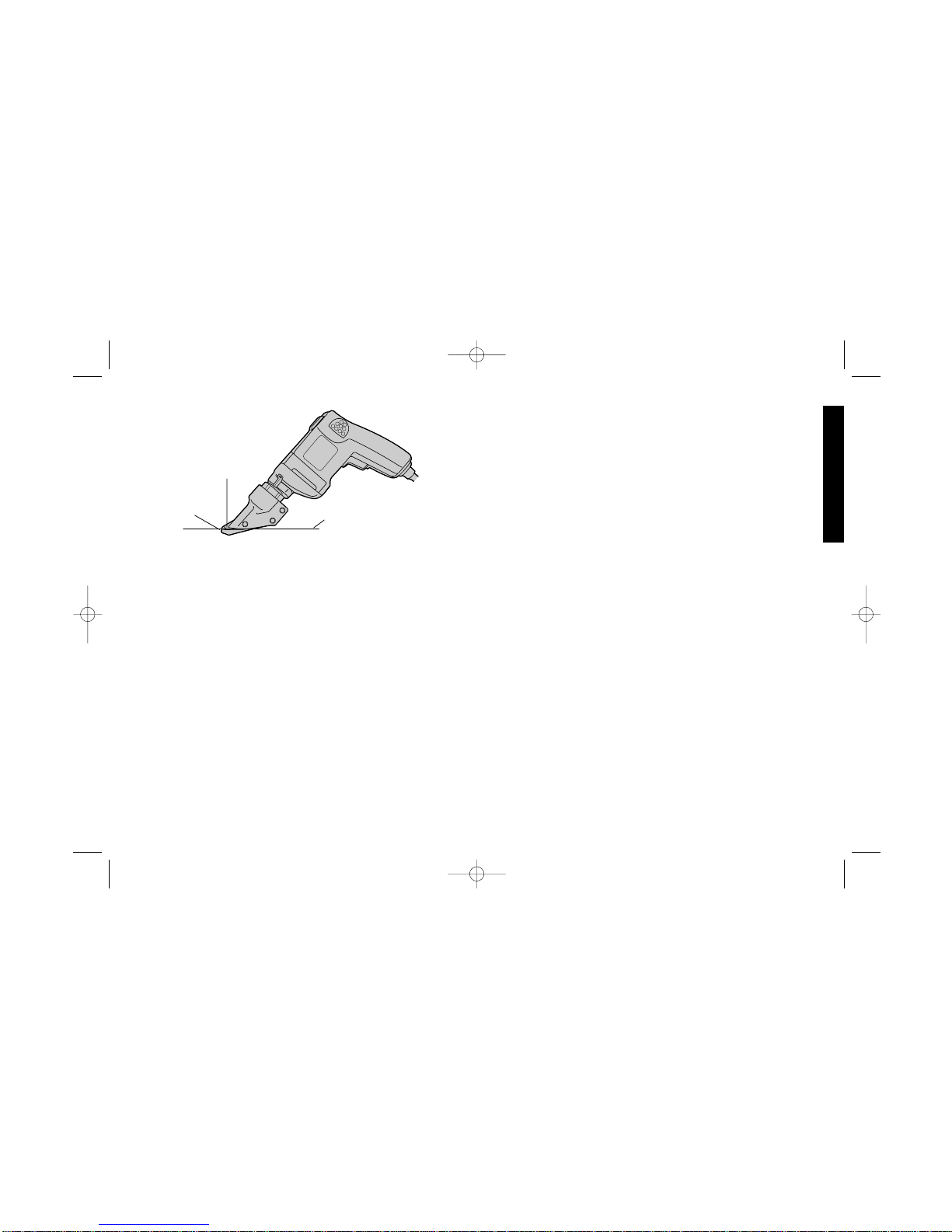
FIG. 4
LOWER
SURFACE OF
SIDE BLADES
BLADE
OPENING
SHEET METAL
To remove cutter blades from shear head, remove 3 cap screws
from shear housing. Be careful not to lose rear spacer bushing when
removing middle cap screw. Remove center blade from housing by
tapping blade gently towards the rear. Side knife and side spacer will
now drop out of the housing.
To remove eccentric bearing assembly from shaft, use an
appropriate wrench to loosen eccentric nut by turning
counterclockwise.
To install eccentric bearing assembly onto shaft, make sure the
large thin washer is first inserted over shaft. Screw eccentric bearing
assembly onto shaft and tighten with appropriate wrench. Lubricate
bearing with a good grade of bearing grease.
To install cutter blades into shear housing, place the side knife
and side spacer into position in the shear housing. Insert center cap
screw through side knife and side spacer with rear spacer bushing
between them. Start cap screw into thread just enough to hold blades
in place. DO NOT TIGHTEN. Insert spacer bushing into hole in center
blade and lubricate. Install center blade into shear housing by tapping
blade gently forward using a drift to line up hole in center blade with
forward holes in housing. Insert and tighten forward cap screw
making sure spacer bushing in center blade stays in position. Apply
good grade of bearing grease to clevis or yoke in center blade where
it rides on the eccentric bearing assembly. Insert rear cap screw into
shear housing but do not completely tighten.
To install shear head assembly onto drive motor, make sure all
cap screws are loosened about 3 or 4 complete turns. Place shear
head onto unit and alternately tighten cap screws snugly to lock head
assembly in place. It may be necessary to gently tap the shear head
into place if it does not readily slip onto the nose of the power unit.
Operation
For accurate work, always clamp or anchor the material to be cut.
DW890/384122 9/1/00 3:24 PM Page 3
Page 7

4
Line up one edge of the tool’s middle blade with the cutting line and
advance blades into the material without forced effort or unnecessary
pressure. A little practice will enable you to determine what forward
pressure gives you the smoothest cutting. It is important to keep the
lower surfaces of the side blades flat on the material being cut
(Figure 4). When cutting curves, do not tilt the tool; keep the side
blades flat and level. For best cutting efficiency, keep blades sharp.
Wear gloves when handling sheet metal. The edges are sharp and
can cause injury.
CAUTION: Do not use the shear with any kind of accessory or
attachment. Such usage might be hazardous.
Adjustment (Figure 5)
To adjust the curl of waste material, the left side knife has elongated
holes. Adjustment may be necessary after changing blades or
material being cut. Loosen cap screws and tap side knife either
forward or backward so that curl of waste does not hit shear housing
or work material while cutting.
Lubrication
All ball bearings are factory lubricated to last the life of the tool. All
sleeve and needle bearings receive their lubrication from grease in
the gear case. Clean and re-lubricate gear case yearly or whenever
English
servicing requires the gear case to be removed. Use type and
quantity of grease shown on the parts bulletin packed with your tool.
Accessories
Recommended accessories for use with your tool are available at
extra cost from your distributor or local service center.
CAUTION: The use of any non-recommended accessory may be
hazardous.
Important
To assure product SAFETY and RELIABILITY, repairs, maintenance
and adjustment (including brush inspection and replacement) should
be performed by authorized service centers or other qualified service
organizations, always using identical replacement parts.
Full Warranty
DEWALT heavy duty industrial tools are warranted for one year from
date of purchase. We will repair, without charge, any defects due to
faulty materials or workmanship. For warranty repair information,
call 1-800-4-D
EWAL T. This warranty does not apply to accessories or
damage caused where repairs have been made or attempted by
others. This warranty gives you specific legal rights and you may
have other rights which vary in certain states or provinces.
In addition to the warranty, D
EWALT tools are covered by our:
30 DAY NO RISK SATISFACTION GUARANTEE
If you are not completely satisfied with the performance of your
D
EWALTheavy duty industrial tool, simply return it to the participating
seller within 30 days for a full refund. Please return the complete unit,
transportation prepaid. Proof of purchase may be required.
FIG. 5
ALTERNATELY
TIGHTEN TO SECURE
DW890/384122 9/1/00 3:24 PM Page 4
Page 8

5
Français
POUR TOUT RENSEIGNEMENT SUPPLÉMENTAIRE SUR CET
OUTIL OU TOUT AUTRE OUTIL D
E
WALT, COMPOSER SANS
FRAIS LE NUMÉRO:
1 800 4-DEWALT (1 800 433-9258)
IMPORTANTES
MESURES DE SÉCURITÉ
(POUR TOUS LES OUTILS)
AVERTISSEMENT : Afin de réduire les risques d’incendie, de
secousses électriques ou de blessures lorsqu’on utilise des outils
électriques, il faut toujours respecter les mesures de sécurité
suivantes.
Double isolation
Les outils à double isolation comportent deux couches distinctes
d’isolant électrique ou une double épaisseur d’isolant qui protègent
l’utilisateur contre les risques de blessures provenant du système
électrique de l’outil.
Ce système de double isolation élimine le besoin de mettre les outils
à la terre. En effet, l’outil est muni d’une fiche à deux broches, ce qui
permet d’utiliser une rallonge ordinaire sans avoir à se soucier
d’assurer la mise à la terre.
NOTE : La double isolation ne dispense pas des mesures de sécurité
normales lors de l’utilisation de l’outil. Elle vise à procurer une
protection supplémentaire contre les blessures que peut entraîner
une défectuosité de l’isolant électrique à l’intérieur de l’outil.
MISE EN GARDE : Lors de l’entretien, N’UTILISER QUE DES
PIÉCES DE RECHANGE IDENTIQUES. Réparer ou remplacer les
cordons endommagés.
Fiche polarisée(DW890, DW891)
Afin de réduire les risques de secousses électriques, l’outil est muni
d’une fiche polarisée (une lame plus large que l’autre). Ce genre de
fiche n’entre que d’une façon dans une prise polarisée. Lorsqu’on
ne peut insérer la fiche à fond dans la prise, il faut tenter de le faire
après avoir inversé les lames de côté. Si la fiche n’entre toujours
TÉTE
PIVOTANTE
INTERRUPTEUR
À DÉTENTE
COUTEAU
DW890/384122 9/1/00 3:24 PM Page 5
Page 9

6
pas dans la prise, il faut communiquer avec un électricien certifié afin
qu’il installe une prise appropriée. Il ne faut en aucun cas modifier la
fiche.
LIRE TOUTES LES DIRECTIVES.
• BIEN DÉGAGER LA SURFACE DE TRAVAIL. Des surfaces et
des établis encombrés peuvent être la cause de blessures.
• TENIR COMPTE DU MILIEU DE TRAVAIL. Protéger les outils
électriques de la pluie. Ne pas s’en servir dans des endroits
humides ou mouillés. Bien éclairer la surface de travail.
• SE PROTÉGER CONTRE LES SECOUSSES ÉLECTRIQUES.
Éviter tout contact avec des objets mis à la terre, comme des
tuyaux, radiateurs, cuisinières, réfrigérateurs et autres objets du
genre.
• ÉLOIGNER LES ENFANTS. Tous les visiteurs doivent être tenus
à l’écart de l’aire de travail et il faut les empêcher de toucher à
l’outil ou au cordon de rallonge.
• RANGER LES OUTILS INUTILISÉS. Il faut ranger les outils dans
un endroit sec, situé en hauteur ou fermé à clé, hors de la portée
des enfants.
• NE JAMAIS FORCER L’OUTIL. Afin d’obtenir un rendement sûr
et efficace, utiliser l’outil à son rendement nominal.
• UTILISER L’OUTIL APPROPRIÉ. Ne jamais exiger d’un petit outil
ou d’un accessoire le rendement d’un outil de fabrication plus
robuste. Se servir de l’outil selon l’usage prévu (par exemple, ne
pas se servir d’une scie circulaire pour couper des branches
d’arbres ou des bûches).
• PORTER DES VÊTEMENTS APPROPRIÉS. Éviter de porter des
vêtements amples et des bijoux qui peuvent être happés par les
pièces en mouvement. Porter des gants de caoutchouc et des
chaussures à semelle antidérapante pour travailler à l’extérieur.
Protéger la chevelure si elle est longue.
• PORTER DES LUNETTES DE SÉCURITÉ. Porter également un
masque respiratoire si le travail de coupe produit de la poussière.
• NE PAS MANIPULER LE CORDON DE FAÇON ABUSIVE. Ne
pas transporter l’outil par le cordon ni tirer sur ce dernier pour le
débrancher de la prise. Éloigner le cordon des sources de chaleur,
des flaques d’huile et des arêtes tranchantes.
• ASSUJETTIR LA PIÈCE. Immobiliser la pièce à l’aide de brides
ou d’un étau. On peut alors se servir des deux mains pour faire
fonctionner l’outil, ce qui est plus sûr.
• NE PAS DÉPASSER SA PORTÉE. Toujours demeurer dans une
position stable et garder son équilibre.
• PRENDRE SOIN DES OUTILS. Conserver les outils propres pour
qu’ils donnent un rendement supérieur et sûr. Suivre les directives
concernant la lubrification et le remplacement des accessoires.
Inspecter régulièrement le cordon de l’outil et le faire réparer au
besoin à un atelier d’entretien autorisé. Inspecter régulièrement
les cordons de rallonge et les remplacer lorsqu’ils sont
endommagés. S’assurer que les poignées sont toujours propres,
sèches et libres de toute tache d’huile ou de graisse.
• DÉBRANCHER LES OUTILS NON UTILISÉS. Respecter cette
mesure lorsqu’on ne se sert pas de l’outil, ou qu’on doit le réparer
ou en changer un accessoire (comme une lame, un foret ou un
couteau).
• ENLEVER LES CLÉS DE RÉGLAGE. Prendre l’habitude de
vérifier si les clés de réglage ont été retirées avant de faire
démarrer l’outil.
• ÉVITER LES DÉMARRAGES ACCIDENTELS. Ne pas laisser le
doigt sur l’interrupteur lorsqu’on transporte l’outil. S’assurer que
l’interrupteur est à la position hors circuit lorsqu’on branche l’outil.
CORDONS DE RALLONGE PRÉVUS POUR L’EXTÉRIEUR.
Lorsque l’outil est utilisé à l’extérieur, ne se servir que d’un cordon
de rallonge conçu pour l’extérieur et portant la mention appropriée.
Français
DW890/384122 9/1/00 3:24 PM Page 6
Page 10

Calibre minimal des cordons de rallonge
Longueur totale du cordon
25 ft. 50 ft. 75 ft. 100 ft. 125 ft. 150 ft. 175 ft.
7,6 m 15,2 m 22,9 m 30,5 m 38,1 m 45,7 m 53,3 m
Intensité
18 AWG 18 AWG 16 AWG 16 AWG 14 AWG 14 AWG 12 AWG
• DEMEURER VIGILANT. Travailler avec vigilance et faire preuve
de bon sens. Ne pas se servir de l’outil lorsqu’on est fatigué.
• VÉRIFIER LES PIÈCES ENDOMMAGÉES. Vérifier l’alignement
et les attaches des pièces mobiles, le degré d’usure des pièces et
leur montage, ainsi que tout autre facteur susceptible de nuire au
bon fonctionnement de l’outil. Faire réparer ou remplacer tout
protecteur ou toute autre pièce endommagée dans un centre de
service autorisé, sauf si le présent guide fait mention d’un avis
contraire. Confier le remplacement de tout interrupteur défectueux
à un centre de service autorisé. Ne jamais se servir d’un outil
dont l’interrupteur est défectueux.
• NE PAS UTILISER les outils portatifs électriques dans des
endroits où l’atmosphère contient des vapeurs combustibles ou
explosives. Les étincelles que produit le moteur en marche
pourraient enflammer ces produits.
• MISE EN GARDE : Lorsqu’on coupe dans les murs, les
planchers ou tout autre endroit où peuvent se trouver des fils sous
tension, NE PAS TOUCHER À TOUT COMPOSANT MÉTALLIQUE SE TROUVANT À L’AVANT DE L’OUTIL. Ne le saisir que
par ses surfaces de prise isolées afin de se protéger des
secousses électriques.
AVERTISSEMENT : Certains outils, tels que les sableuses
électriques, les scies, les meules, les perceuses ou certains autres
outils de construction, peuvent soulever de la poussière contenant des
produits chimiques susceptibles d’entraîner le cancer, des
malformations congénitales ou pouvant être nocifs pour le système
reproductif. Parmi ces produits chimiques, on retrouve :
• le plomb dans les peintures à base de plomb;
• la silice cristalline dans les briques et le ciment et autres produits de
maçonnerie;
• l’arsenic et le chrome dans le bois de sciage ayant subi un
traitement chimique (CCA).
Le risque associé à de telles expositions peut varier selon la fréquence
avec laquelle on effectue ces travaux. Pour réduire l’exposition à de
tels produits, il faut travailler dans un endroit bien ventilé et utiliser
l’équipement de sécurité approprié tel un masque anti-poussières
spécialement conçu pour filtrer les particules microscopiques.
CONSERVER CES
MESURES
À TITRE DE RÉFÉRENCE.
Moteur
Un moteur DeWALT actionne l’outil DeWALTVeiller à ce que la
tension d’alimentation soit conforme aux exigences de la plaque
signalétique de l’outil.
La mention «volts, 50/60 Hz» ou «c.a. seulement» signifie que l’outil
fonctionne uniquement sur une alimentation en courant alternatif, et
jamais en courant continu.
Une baisse de tension de plus de 10 p. 100 entraîne une perte de
puissance et la surchauffeTous les outils DeWALT sont essayés
avant de quitter l’usineLorsque celui-ci refuse de fonctionner, vérifier
la source de courant électrique.
Interrupteur
Enfoncer l’interrupteur à détente pour mettre l’outil en marche. Pour
l’arrêter, relâcher la détente.
7
Français
DW890/384122 9/1/00 3:24 PM Page 7
Page 11

8
Pour verrouiller la détente en mode de fonctionnement continu,
enfoncer la détente, pousser le bouton de verrouillage vers le haut
(fig. 1) et relâcher doucement la détente. Pour dégager le
mécanisme de verrouillage, enfoncer à fond la détente et la relâcher.
Avant d’utiliser l’outil, toujours s’assurer que le bouton de verrouillage
fonctionne librement. Ne pas oublier de dégager le bouton de
verrouillage de l’interrupteur avant de débrancher l’outil sinon celuici démarrera immédiatement lorsqu’il sera branché. Un tel oubli
présente des risques de dommages ou de blessures. L’interrupteur
à détente et à régulateur de vitesse permet de maîtriser la vitesse
de l’outil. Plus on enfonce la détente, plus la vitesse de la cisaille
augmente.
Démontage et montage (Figures 2 et 3)
Pour retirer la tête du moteur, desserrer les trois vis d’assemblage.
Retirer la tête en la tirant fermement vers l’avant. Il peut être
nécessaire de la balancer légèrement si elle ne glisse pas aisément
hors du moteur.
Pour retirer les couteaux de la tête, retirer les trois vis
d’assemblage du boîtier de la cisaille. Prendre soin de ne pas perdre
le palier de la cale arrière lorsqu’on retire la vis d’assemblage
centrale. Enlever le couteau central du boîtier en frappant
légèrement le couteau vers l’arrière. Le couteau latéral et la cale
latérale tombent ensuite du boîtier.
Pour retirer le roulement excentrique équipé de l’arbre, se servir
d’une clé appropriée afin de desserrer l’écrou excentrique en le
faisant tourner dans le sens antihoraire.
Pour installer le roulement excentrique équipé sur l’arbre,
s’assurer d’insérer d’abord la grosse rondelle mince sur l’arbre.
Visser le roulement excentrique équipé sur l’arbre et le serrer à l’aide
d’une clé appropriée. Lubrifier le roulement avec de la graisse à
roulements de bonne qualité.
Pour installer les couteaux dans le boîtier, placer le couteau
Français
FIG. 1
BOUTON DE
VERROUILLAGE
FIG. 2
VIS
D’ASSEMBLAGE
BOITIER
ROULEMENT
EXCENTRIQUE
ÉQUIPÉ
RONDELLE
FIG. 3
COUTEAU LATÉRAL ET
CALE LATÉRALE
PALIERS DE
CALES
COUTEAU
LATÉRAL
GAUCHE
DW890/384122 9/1/00 3:24 PM Page 8
Page 12

9
Français
latéral et la cale latérale dans le boîtier. Insérer la vis d’assemblage
centrale dans le couteau latéral et la cale latérale en plaçant le palier
de la cale arrière entre eux. Serrer à peine la vis d’assemblage afin
de retenir les couteaux en place. NE PAS SERRER. Insérer le palier
de la cale dans le trou du couteau central et le lubrifier. Insérer le
couteau central dans le boîtier en frappant légèrement le couteau
vers l’avant et en alignant le trou du couteau central sur les trous à
l’avant du boîtier. Insérer et serrer la vis d’assemblage avant en
s’assurant que le palier de la cale du couteau central reste en place.
Enduire la manille ou la chape du couteau central de graisse
à roulements de bonne qualité lorsqu’elle repose contre le roulement
excentrique équipé. Insérer la vis d’assemblage arrière dans le
boîtier mais ne pas la serrer complètement.
Pour installer la tête sur le moteur, s’assurer que toutes les vis
d’assemblage sont desserrées d’environ 3 ou 4 tours complets.
Placer la tête et serrer les vis d’assemblage en alternant afin de
bloquer la tête en place. Il peut être nécessaire de frapper
légèrement la tête pour la faire glisser en place si elle ne se place pas
facilement sur le nez du bloc-moteur.
Fonctionnement
Toujours fixer ou ancrer le matériau à découper afin d’assurer la
précision du travail. Aligner un rebord du couteau central de l’outil sur
la ligne de coupe et faire avancer les couteaux dans le matériau sans
forcer l’outil ni y exercer une pression excessive. Avec un peu de
pratique, on peut déterminer quelle pression avant procure une
coupe en douceur. Il est important de laisser les surfaces inférieures
des couteaux latéraux reposer à plat contre le matériau à couper
(fig. 4). Lorsqu’on coupe des courbes, ne pas faire basculer l’outil.
Laisser les couteaux latéraux à plat et de niveau. Afin d’optimiser la
coupe, s’assurer que les couteaux sont affûtés. Porter des gants
lorsqu’on travaille de la tôle. Les rebords en sont tranchants et cela
présente des risques de blessures.
MISE EN GARDE : Ne pas utiliser la cisaille avec tout accessoire.
FIG. 4
FIG. 5
SURFACE
INFÉRIEURE
DES COUTEAUX
LATÉRAUX
OUVERTURE DU
COUTEAU
TOLE
SERRER EN
ALTERNANT AFIN DE
FIXER
DW890/384122 9/1/00 3:24 PM Page 9
Page 13

10
Français
Une telle utilisation peut être dangereuse.
Réglage (Figure 5)
Le couteau latéral gauche comporte des trous allongés afin de régler
la courbure du matériau inutile. Il peut être nécessaire d’en modifier
le réglage lorsqu’on remplace les couteaux ou lorsqu’on change de
matériau à couper. Desserrer les vis d’assemblage et frapper
légèrement le couteau latéral vers l’avant ou vers l’arrière de sorte
que le matériau inutile ne vienne pas frapper contre l’outil ni le bon
matériau pendant la coupe.
Lubrification
Il est conseillé d’ajouter une quantité minimale de graisse aux
engrenages lorsqu’on remplace les balais (ou de redistribuer la
graisse qui reste dans le boîtier).
Les roulements à billes de cet outil ont été lubrifiés en usine et il n’est
pas nécessaire de les lubrifier de nouveau.
Accessoires
Les accessoires recommandés pour cet outil sont vendus chez les
détaillants ou au centre de service de la région. Pour trouver un
accessoire, communiquer avec le détaillant ou le centre de service
de la région.
MISE EN GARDE : L’utilisation de tout autre accessoire non
recommandé pour l’outil peut être dangereuse.
Important
Pour assurer la SÉCURITÉ D’EMPLOI et la FIABILITÉ de l’outil, n’en
confier la réparation, l’entretien et les rajustements (y compris
l’inspection et le remplacement des balais) qu’à un centre de service
ou à un atelier d’entretien autorisé n’utilisant que des pièces de
rechange identiques.
Garantie complète
Les outils industriels de service intensif DEWALT sont garantis
pendant un an à partir de la date d’achat. Toute pièce d’un outil
D
EWALT qui s’avérait défectueuse en raison d’un vice de matière ou
de fabrication sera réparée ou remplacée sans frais. Pour obtenir de
plus amples renseignements sur les réparations couvertes par la
garantie, composer le 1 (800) 4-D
EWALT (! (800) 433-9258). La ga
rantie ne couvre pas les accessories ni les réparations tentées ou
effectuées par des tiers. Les modalités de la présente garantie
donnent des droits légaux spécifiques. L’utilisateur peut également
se prévaloir d’autres droits selon l’état ou la province qu’il habite.
En outre, la garantie suivante couvre les outils D
EWALT.
GARANTIE DE SATISFACTION DE 30 JOURS OU ARGENT REMIS
Si, pour quelque raison que ce soit, l’outil industriel de service intensif
D
E
WALT ne donne pas entière satisfaction, il suffit de le retourner
chez le marchand participant dans les 30 jours suivant la date
d’achat afin d’obtenir un remboursement complet. Il faut retourner,
port payé, l’outil complet. On peut exiger une preuve d’achat.
Voir la rubrique “Outils électriques”
des Pages Jaunes
pour le service et les ventes.
DW890/384122 9/1/00 3:24 PM Page 10
Page 14

Reglas generales de seguridad
¡ADVERTENCIA! Lea y comprenda todas las instrucciones.
No hacerlo puede originar riesgos de choque eléctrico, incendio y
lesiones personales de gravedad.
CONSERVE EST AS INSTRUCCIONES
AREA DE TRABAJO
• Conserve su área de trabajo limpia y bien iluminada. Las
bancas amontonadas y las zonas oscuras propician los
accidentes.
• No opere herramientas eléctricas en atmósferas explosivas,
como en presencia de líquidos, gases o polvos inflamables.
Las herramientas eléctricas producen chispas que pueden originar
la ignición de los polvos o los vapores.
• Conserve a observadores, niños y visitantes alejados
mientras opera una herramienta eléctrica. Las distracciones
pueden ocasionar que pierda el control.
SEGURIDAD ELECTRICA
• Las herramientas aterrizadas deben conectarse a una toma
de corriente correctamente instalada y aterrizada de
conformidad con todos los códigos y reglamentos. Nunca
elimine la pata de conexión a tierra ni modifique la clavija en
ninguna manera. No utilice adaptadores. Verifique con un
electricista calificado si tiene dudas acerca de la conexi–n a
tierra de su toma. Si las herramientas tienen algún mal
funcionamiento eléctrico, la tierra proporciona una vía para alejar
del operador la electricidad.
• Las herramientas con doble aislamiento están equipadas con
una clavija polarizada (con una pata más ancha que la otra.)
Esta clavija se acoplará únicamente en una toma de corriente
polarizada de una manera. Si la clavija no se acopla al
contacto, inviértala. Si aún así no se ajusta, comuníquese con
un electricista calificado para que le instalen una toma de
11
Español
CABEZA
GIRATORIA
INTERRUPTOR DE
GATILLO
CUCHILLA
DEWALT...PARA TRABAJOS PESADOS
Las herramientas industriales DeWalt de alto rendimiento se han
fabricado para las más duras condiciones industriales y de
construcción. El diseño de cada una de las herramientas de esta
línea desde taladros hasta lijadoras y esmeriladoras es resultado de
su empleo bajo rigurosas condiciones en centros de trabajo e
instalaciones industriales. Cada instrumento se ha fabricado con
precisión extrema bajo sistemas avanzados de manufactura y rígido
control de calidad. Cada herramienta se verifica concienzudamente
antes de dejar la fábrica, para asegurarse de que satisface sus
estándares de durabilidad, confiabilidad y potencia.
D
EWALT Para trabajos pesados_LO GARANTIZAMOS.
Epecificaciones DW890 DW891
Tensión de alimentación 120 V CA/CD 120 V CA/CD
Potencia nominal: 470 W 470 W
Frecuencia de operación: 60 Hz 60 Hz
Consumo de corriente: 5 A 5 A
DW890/384122 9/1/00 3:24 PM Page 11
Page 15

12
corriente polarizada apropiada. El doble aislamiento elimina la
necesidad de cables con tres hilos y sistemas de alimentación con
conexión a tierra.
• Evite el contacto corporal con superficies aterrizadas tales
como tuberías, radiadores, hornos y refrigeradores. Hay un
gran riesgo de choque eléctrico si su cuerpo hace tierra.
• No exponga las herramientas eléctricas a la lluvia o a
condiciones de mucha humedad. El agua que se introduce en
las herramientas aumenta el riesgo de descargas eléctricas.
• No maltrate el cable. Nunca tome el cable para transportar
una herramienta ni para desconectarla de la toma de
corriente. Consérvelo alejado de calor aceite, bordes afilados
o piezas móviles. Cambie inmediatamente los cables
dañados. Los cables dañados aumentan el riego de choque
eléctrico.
• Cuando opere una herramienta eléctrica a la intemperie,
utilice una extensión marcada “W-A” o “W”. Estas extensiones
están clasificadas para uso a la intemperie y para reducir el riesgo
de choques eléctricos. Cuando utilice una extensión, asegúrese
de emplear una con el calibre suficiente para soportar la corriente
necesaria para su herramienta. Una extensión con calibre
inadecuado causará una caída en el voltaje de la línea resultando
en pérdida de potencia y sobrecalentamiento. La tabla siguiente
muestra el calibre correcto para usarse, relativo a la longitud de la
extensión y el amperaje mencionado en la placa de identificación.
Si tiene dudas, utilice el calibre siguiente. Mientras más pequeño
sea el número del calibre, mayor será su capacidad.
Calibre mínimo requerido (AWG) para cables de extensión
Longitud total del cable de extensión
25 ft. 50 ft. 75 ft. 100 ft. 125 ft. 150 ft. 175 ft.
7.,6 m 15,2 m 22,9 m 30,5 m 38,1 m 45,7 m 53,3 m
Calibre promedio del alambre
18 AWG 18 AWG 16 AWG 16 AWG 14 AWG 14 AWG 12 AWG
SEGURIDAD PERSONAL
• Esté alerta concéntrese en lo que está haciendo. Recurra al
sentido común cuando opere una herramienta eléctrica. No
opere ninguna herramienta si se encuentra fatigado o bajo la
influencia de drogas, alcohol o medicamentos. Un momento
de desatención mientras se operan herramientas eléctricas puede
ocasionar lesiones graves.
• Vístase de manera adecuada. No tenga puestas ropas o
artículos de joyería flojos. Cubra su cabello si lo tiene largo.
Conserve su cabello, sus ropas y guantes alejados de las
piezas móviles. Las piezas de vestir flojas, las joyas y el cabello
largo pueden resultar atrapados por las piezas móviles.
• Evite el encendido accidental. Asegúrese que el interruptor
esté en posición de apagado antes de conectar. Sostener una
herramienta con el dedo en el interruptor o conectarla sin fijarse si
el interruptor está en posición de encendido propicia los
accidentes.
• Retire las llaves de ajuste antes de encender la herramienta.
Una llave que se deja en una pieza giratoria puede ocasionar
lesiones personales.
• No se sobreextienda. Conserve siempre los pies bien
apoyados, al igual que el equilibrio. La posición correcta de los
pies y el equilibrio permiten controlar mejor la herramienta en
situaciones inesperadas.
• Utilice equipo de seguridad. Siempre utilice protección en
los ojos. Se deben utilizar mascarillas contra polvo, zapatos
Español
DW890/384122 9/1/00 3:24 PM Page 12
Page 16

13
Español
antiderrapantes, casco o protectores para los oídos para tener las
condiciones apropiadas.
USO Y CUIDADOS DE LA HERRAMIENTA
• Utilice prensas u otros medios prácticos para asegurar y
apoyar la pieza de trabajo en una plataforma estable. Sujetar
las piezas con la mano o contra su cuerpo es inestable y puede
originar la pérdida de control.
• No fuerce la herramienta. Emplee la herramienta correcta para
su aplicación. La herramienta correcta hará el trabajo mejor y de
manera más segura y bajo las especificaciones para las que fue
diseñada.
• No utilice la herramienta si el interruptor no enciende y apaga.
Cualquier herramienta que no pueda controlarse por medio del
interruptores peligrosa y debe reemplazarse.
• Desconecte la clavija de la toma de corriente antes de hacer
cualquier ajuste, cambio de accesorios o de guardar la
herramienta. Tales medidas de seguridad preventivas reducirán
el riesgo de que la herramienta se encienda accidentalmente.
• Guarde las herramientas fuera del alcance de los niños y de
otras personas no capacitadas. Las herramientas son
peligrosas en manos de personas no capacitadas.
• Cuide sus herramientas. Conserve las herramientas de corte
afiladas y limpias. Las herramientas que reciben un
mantenimiento adecuado, con piezas de corte afiladas,
difícilmente se atascan y son más fáciles de controlar.
• Verifique la alineación de las piezas móviles, busque fracturas
en las piezas y cualesquiera otras condiciones que puedan
afectar la operación de las herramientas. Si está dañada, lleve
su herramienta a servicio antes de usarla de nuevo. Muchos
accidentes se deben a herramientas con mantenimiento pobre.
• Solamente use accesorios que el fabricante recomiende para
su modelo de herramienta. Los accesorios que estén diseñados
para una herramienta, pueden volverse peligrosos cuando se
emplean con otra.
ADVERTENCIA : Parte del polvo creado al lijar, aserruchar, moler o
perforar con máquina, así como al realizar otras actividades de la
construcción, contiene substancias químicas que se sabe producen
cáncer, defectos congénitos u otras afecciones reproductivas. Algunos
ejemplos de esas substancias químicas son:
• plomo de pinturas a base de plomo,
• sílice cristalizado de ladrillos y cemento y otros productos de
albañilería, y
• arsénico y cromo de la madera químicamente tratada (CCA).
El riesgo al contacto con estas substancias varía, según la frecuencia
en que se haga este tipo de trabajo. Para reducir la exposición a esas
substancias químicas: trabaje en un área bien ventilada, y trabaje con
equipos de seguridad aprobados, tales como máscaras contra el polvo
especialmente diseñadas para filtrar las partículas microscópicas.
•REVISE LAS PARTES DAÑADAS. Antes de seguir utilizando su
herramienta, una guarda u otra parte que esté dañada debe ser
revisada cuidadosamente para determinar si operará
apropiadamente y realizará la función para la que está destinada.
Verifique la alineación y la sujeción de las piezas móviles, ruptura
en las piezas, sus montajes y cualesquiera otras condiciones
que pudiesen afectar su operación. Una guarda u otras pieza
dañadas deberán repararse o reemplazarse por un centro de
servicio autorizado, a menos que se indique lo contrario en este
manual de instrucciones. Haga reemplazar los interruptores
defectuosos por un centro de servicio autorizado. No utilice la
herramienta si el interruptor no funciona.
PRECAUCION: Cuando corte en muros, pisos o dondequiera que
pudiese encontrar cables eléctricos vivos, ¡NO TOQUE
NINGUNA PIEZA METALICA DE LA HERRAMIENTA! Sujétela
únicamente por las superficies aislantes para evitar descargas
eléctricas en el caso de cortar un cable vivo.
DW890/384122 9/1/00 3:24 PM Page 13
Page 17

14
Motor
Su herramienta DeWalt cuenta con un motor DeWalt interconstruido.
Asegúrese que el voltaje de su toma de corriente concuerda con las
especificaciones de la placa de la unidad. 120 Volts, 60 Hz, AC/DC
indican que su herramienta puede operarse con corriente alterna o
con corriente continua. Las disminuciones del voltaje mayores de
10% harán que la herramienta pierda potencia y se sobrecaliente.
T odas las herramientas DeW alt se han probado en fábrica; si ésta no
operara, verifique la toma de corriente del sitio en que la opera.
Interruptor
Oprima el interruptor de gatillo para encender la herramienta,
suéltelo para apagarla. Para asegurar el interruptor en posición de
encendido para operación continua, oprima el gatillo, empuje hacia
arriba el botón de encendido permanente (figura 1), y a continuación
libere suavemente el gatillo. Para liberar el mecanismo de encendido
permanente, oprima a fondo el gatillo y suéltelo a continuación.
Antes de emplear la herramienta cada vez, asegúrese que el
mecanismo de liberación del botón del seguro funciona libremente.
Asegúrese de liberar el botón del seguro antes de desconectar la
clavija de la toma de corriente. No hacerlo ocasionará que la
herramienta se encienda inmediatamente la próxima vez que la
conecte, con el consiguiente riesgo de daños y lesiones. El gatillo
interruptor de velocidad variable le permite controlar la velocidad.
Mientras más a fondo oprima el gatillo, mayor será la velocidad de
la cizalla.
Desensamblaje y ensamblaje
(figuras 2 y 3)
Para retirar la cabeza de la cizalla del motor, afloje los 3 tornillos
con cabeza redonda. Saque la cabeza de la cizalla tirando de ella
con firmeza hacia adelante. Puede requerirse una pequeña torsión
sin la cabeza no se desliza con facilidad.
Español
FIG. 1
BOTON DE
ENCENDIDO
PERMANENTE
FIG. 2
TORNILLOS DE
CABEZA REDONDA
CARCAZA
MONTAJE DE
BALERO
EXCENTRICO
ROLDANA
FIG. 3
CUCHILLA LATERAL
Y ESPACIADOR
LATERAL
BUJES
ESPACIADORES
CUCHILLA LATERAL
IZQUIERDA
DW890/384122 9/1/00 3:24 PM Page 14
Page 18

15
Español
Para retirar las cuchillas de la cabeza, saque los 3 tornillos de la
carcaza de la cizalla. Sea cuidadoso para no perder el buje
espaciador trasero cuando quite el tornillo de enmedio. Saque la
cuchilla central de la carcaza aplicándole unos golpecillos hacia
atrás. La cuchilla y el espaciador laterales saldrán ahora de la
carcaza.
Para retirar el montaje del balero excéntrico de la flecha, utilice una
llave apropiada para aflojar la tuerca excéntrica girándola en sentido
contrario a las manecillas del reloj.
Para instalar el montaje del balero excéntrico en la flecha,
asegúrese que la roldana delgada grande sea lo primero en
colocarse en la flecha. Atornille el montaje del balero excéntrico en
la flecha y apriételo con la llave apropiada. Lubrique el balero con
una cantidad generosa de grasa para baleros.
Para instalar las cuchillas en la carcaza de la cizalla, colóquela
cuchilla y el espaciador laterales en su posición en la carcaza.
Inserte el tornillo a través de la cuchilla y el espaciador laterales con
el buje espaciador entre ellos. Enrosque el tornillo lo suficiente para
sujetar las cuchillas en su posición. NO APRIETE. Inserte el buje
espaciador en el orificio de la cuchilla central y lubrique. Instale la
FIG. 4
FIG. 5
SUPERFICIE
INFERIOR DE
LAS CUCHILLAS
LATERALES
ABERTURA DE LA
CUCHILLA
LAMINA DE METAL
APRIETE
ALTERNATIVAMENTE
PARA ASEGURAR
cuchilla central en la cizalla aplicándole unos golpecillos utilizando
un punzón para alinear el orificio de la cuchilla con los orificios
delanteros de la carcaza. Inserte el tornillo delantero y apriételo,
asegurándose que el buje espaciador que se encuentra en la
cuchilla central permanezca en su posición. Aplique una cantidad
generosa de grasa para baleros a la abrazadera o al yunque en la
cuchilla central en la parte que monta en el balero excéntrico. Inserte
el tornillo trasero en la carcaza pero no apriete por completo.
Para instalar el montaje de la cabeza de la cizalla en el motor,
asegúrese que todos los tornillos estén flojos aproximadamente 3 o
4 vueltas completas. Coloque la cabeza de la cizalla en la unidad y
apriete alternativamente los tornillos hasta asegurar la cabeza en su
sitio. Puede ser necesario aplicar unos golpecillos a la cabeza de la
cizalla para colocarla en su sitio si no se desliza con facilidad en la
nariz de la unidad de poder.
Operación
Para trabajar con precisión, siempre sujete o prense el material con
el que vaya a trabajar. Haga coincidir uno de los filos de la cuchilla
DW890/384122 9/1/00 3:24 PM Page 15
Page 19

16
Español
central de la herramienta con la línea de corte y avance las cuchillas
en el material sin esforzarse ni aplicar presión innecesaria. Con un
poco de práctica usted podrá determinar con qué presión hará el
corte más suavemente. Es muy importante conservar los bordes
inferiores de las cuchillas laterales planos sobre el material (figura 4).
Cuando corte curvas, evite levantar la herramienta; conserve las
cuchillas laterales planas y niveladas. Para la mayor eficiencia en el
corte, conserve afiladas las cuchillas. Utilice guantes para manejar
lámina de metal. Los bordes son afilados y pueden causarle una
lesión. PRECAUCION: No utilice la cizalla con ningún tipo de
accesorio o dispositivo. Puede ser peligroso.
Ajustes (figura 5)
Para ajustar la curvatura del material de desperdicio, la cuchilla del
lado izquierdo tiene orificios elongados. Puede ser necesario ajustar
las cuchillas después de cambiarlas o de cambiar el material con que
se trabaja. Afloje los tornillos y mueva la cuchilla hacia adelante o
hacia atrás de manera que el material de desperdicio no haga
contacto con la carcaza ni con la pieza de trabajo al cortar.
Mantenimiento
Utilice únicamente un jabón suave y un trapo húmedo para limpiar
la herramienta. Nunca permita que se introduzca ningún líquido en la
herramienta, ni sumerja ninguna parte de ésta en ningún líquido.
Se han empleado baleros auto lubricantes en la fabricación de esta
herramienta y no se requiere de lubricación periódica. En el
improbable caso que su herramienta llegase a requerir servicio,
llévela a un centro de servicio autorizado.
Importante
Para garantizar la SEGURIDAD y la CONFIABILIDAD del producto,
deberán hacerse reparaciones, mantenimiento y ajustes (incluyendo
revisión y cambio de los carbones) por centros autorizados de
servicio u otras organizaciones calificadas que empleen siempre
refacciones idénticas
PARA REPARACION Y SERVICIO DE SUS HERRAMIENT AS
ELECTRICAS FAVOR DE DIRIGIRSE AL CENTRO DE SERVICIO MAS
CERCANO
CULIACAN
Av. Nicolas Bravo #1063 Sur (91 671) 242 10
GAUDALAJARA
Av. La Paz #1770 (91 3) 826 69 78.
LEON
Polara #32 (91 471) 314 56
MEXICO
Eje Lázaro Cárdenas #18 Local D, Obrera 553-9377
MERIDA
Calle 63 #459 (91 99) 23 54 90
MONTERREY
Av. Francisco I. Madero Pte. 1820-A (91 83) 72 11 25
PUEBLA
17 Norte #2057 (91 22) 46 90 20
QUERETARO
Av. Madero 139 Pte. (91 42) 14 60 60
SAN LOUIS POTOSI
Pedro Moreno #408 Fracc. la Victoria (91 48) 14 25 67
TORREON
Blvd. Independencia, 96 pte. (91 17) 16 52 65
VERACRUZ
Prolongación Diaz Miron #4280 (91 29) 21 70 18
VILLAHERMOSA
Zaragoza #105 (91 93) 12 53 17
PARA OTRAS LOCALIDADES LLAME AL: 326 7100
Accesorios
Dispone usted de los accesorios para su herramienta por un cargo
adicional con su distribuidor local autorizado Se incluye una lista
completa de los centros de servicio con su herramienta..Si necesita
DW890/384122 9/1/00 3:24 PM Page 16
Page 20

17
Español
ayuda para encontrar cualquier accesorio, por favor comuníquese con
D
EWALT Industrial Tool Co., 701 East Joppa Road, Baltimore, MD
21286 o llame al teléfono 1-800-732-4441.
Garantía Completa
Las herramientas industriales DEWalt están garantizadas durante un año a
partir de la fecha de compra. Repararemos, sin cargos, cualquier falla debida
a material o mano de obra defectuosos. Por favor regrese la unidad completa,
con el transporte pagado, a cualquier Centro de Servicio para Herramientas
Industriales de DEWalt o a las estaciones de servicio autorizado enlistadas
bajo "Herramientas Eléctricas" en la Sección Amarilla. Esta garantía no se
aplica a los accesorios ni a daños causados por reparaciones efectuadas
por terceras personas. Esta garantía le otorga derechos legales específicos,
y usted puede tener otros derechos que pueden variar de estado a estado.
En adición a la garantía, las herramientas DEWALT están amparadas por
nuestra:
GARANTÍA DE SATISFACCIÓN SIN RIESGO POR 30 DÍAS
Si usted no se encuentra completamente satisfecho con el desempeño de
su herramienta industrial DEWalt, sencillamente devuélvala a los vendedores
participantes durante los primeros 30 días después de la fecha de compra
para que le efectúen un reembolso completo. Por favor regrese la unidad
completa, con el transporte pagado. Se puede requerir prueba de compra.
IMPORTADO: DEWALT S.A. DE C.V.
BOSQUES DE CIDROS ACCESO RADIATAS NO. 42
COL. BOSQUES DE LAS LOMAS.
05120 MÉXICO, D.F
TEL. 326-7100
SECCI N
AMARILLA
Si funciona…
y funciona muy bien.
Para servicio y ventas consulte
“HERRAMIENTAS ELECTRICAS”
en la sección amarilla.
DW890/384122 9/1/00 3:24 PM Page 17
 Loading...