

Page 1

IF YOU SHOULD EXPERIENCE A PROBLEM WITH YOUR DEWALT PURCHASE,
CALL 1-800-4-DEWALT
IN MOST CASES, A DEWALT REPRESENTATIVE CAN RESOLVE
YOUR PROBLEM OVER THE PHONE.
IF YOU HAVE A SUGGESTION OR COMMENT, GIVE US A CALL.
YOUR FEEDBACK IS VITAL TO THE SUCCESS OF DEWALT'S
QUALITY IMPROVEMENT PROGRAM.
Questions? Visit us at www.dewalt.com
Des questions ? Rendez nous visite _ www.dewalt.com
_Tiene preguntas? Visitenos en www.dewalt.com
INSTRUCTION MANUAL INSTRUCTIVO DE OPERACION, CENTROS DE SERVlCIO Y POLIZA DE
GUIDE D'UTILISATION GARANT[A. ADVERTENCIA: LEASE ESTE INSTRUCTIVO ANTES DE
MANUAL DE INSTRUCCIONES USARELPRODUOTO.
DWS709
12" (305 ram) Double Bevel Sliding Compound Miter Saw
Scie coulissante _ onglet mixte 305 mm (12 po)
Sierra ingletadora compuesta deslizante de doble bisel de 305 mm (12")
Page 2
F
Definitions: Safety Guidelines
The definitions below describe the level of severity for each signal word. Please read the
manual and pay attention to these symbols.
_DANGER: Indicates an imminently hazardous situation which, if not avoided, will
result in death or serious injury.
A WARNING: Indicates a potentially hazardous situation which, if not avoided, could
result in death or serious injury.
A CAUTION: Indicates a potentially hazardous situation which, if not avoided, may
result in minor or moderate injury.
NOTICE: Indicates a practice not related to personal injury which, if not avoided,
may result in property damage.
\ J
IF YOU HAVE ANY QUESTIONS OR COMMENTS ABOUT THIS OR ANY DEWALTTOOL,
CALL US TOLL FREEAT: 1-800-4-DEWALT (1-800-433-9258}.
_ WARNING: To reduce the risk of injury, read the instruction manual.
Important Safety Instructions
_ ARNING! Read all safety warnings and all instructions. Failure to follow the
warnings and instructions may result in electric shock, fire and/or serious injury,
SAVE ALL WARNINGS AND INSTRUCTIONS
FOR FUTURE REFERENCE
Double Insulation
Double insulated tools are constructed throughout with two separate layers of electrical
insulation or one single layer of reinforced insulation between you and the tool's electrical
system. Tools built with this insulation system are not intended to be grounded. As a result,
your tool is equipped with a two prong plug which permits you to use extension cords without
concern for maintaining a ground connection.
NOTE: Double insulation does not take the place of normal safety precautions when
operating this tool. The secondary insulation system is for protection against injury resulting
from a possible failure of the primary insulation within the tool.
_CAUTION: WHEN SERVICING USE ONLY IDENTICAL REPLACEMENT PARTS. Repair or
replace damaged cords.
Polarized Plugs
Polarized plugs (one blade is wider than the other) are used on equipment to reduce the risk
of electric shock. When provided, this plug will fit in the polarized outlet only one way. If the
plug does not fit fully in the outlet, reverse the plug. If it still does not fit, contact a qualified
electrician to install the proper outlet. Do not change the plug in any way.
Safety Instructions for All Tools
AWARNING: To reduce the risk of eye injury, ALWAYS use eye protection when
operating the miter saw.
• KEEP GUARD IN PLACE and in working order.
• REMOVE ADJUSTING KEYS AND WRENCHES. Form habit of checking to see that
keys and adjusting wrenches are removed from spindle before turning tool on. Tools,scrap
pieces, and other debris can be thrown at high speed, causing injury,
• KEEP WORK AREA CLEAN. Cluttered areas and benches invite accidents.
• DO NOT USE THE MACHINE IN A DANGEROUS ENVIRONMENT. The use of power
tools in damp or wet locations or in rain can cause shock or electrocution. Keep your work
area well-lit to avoid tripping or placing arms, hands, and fingers in danger.
• KEEP CHILDREN AWAY. All visitors should be kept at a safe distance from work area.
Your shop is a potentially dangerous environment.
• MAKE WORKSHOP CHILDPROOF with padlocks, master switches, or by removing
starter keys. The unauthorized start-up of a machine by a child or visitor may result in injury,
• DON'T FORCE TOOL. It will do the job better and be safer at the rate for which it was
designed.
• USE RIGHT TOOL. Don't force tool or attachment to do a job for which it was not
designed. Using the incorrect tool or attachment may result in personal injury,
• WEAR PROPER APPAREL. Do not wear loose clothing, gloves, neckties, rings,
bracelets, or other jewelry which may get caught in moving parts. Nonslip footwear is
recommended. Wear protective hair covering to contain long hair.
• ALWAYS USE SAFETY GLASSES. Everyday eyeglasses are NOT safety glasses. Also
use face or dust mask if cutting operation is dusty, ALWAYS WEAR CERTIFIED SAFETY
EQUIPMENT."
• ANSI Z87.1 eye protection (CAN/CSA Z94.3).
• ANSI $12.6 ($3.19) hearing protection.
• NIOSH/OSHA/MSHA respiratory protection.
• SECURE THE WORKPIECE. Use clamps or a vise to hold the workpiece on the table
and against the fence or when your hand will be dangerously close to the blade within 6"
(152 mm). It is safer than using your hand and it frees both hands to operate tool
• DON'T OVERREACH. Keep proper footing and balance at all times. Loss of balance may
cause personal injury,
• MAINTAIN TOOLS WITH CARE. Keep tools sharp and clean for best and safest
performance. Follow instructions for lubricating and changing accessories. Poorly
maintained tools and machines can further damage the tool or machine and/or cause
injury,
• TURN THE MACHINE "OFF" AND DISCONNECT THE MACHINE FROM THE
POWER SOURCE before installing or removing accessories, before adjusting or changing
set-ups, when making repairs or changing locations. An accidental start-up can cause
injury, Do not touch the plug's metal prongs when unplugging or plugging in the cord.
• REDUCE THE RISK OF UNINTENTIONAL STARTING. Make sure that the switch is in
the "OFF" position before plugging in the power cord.
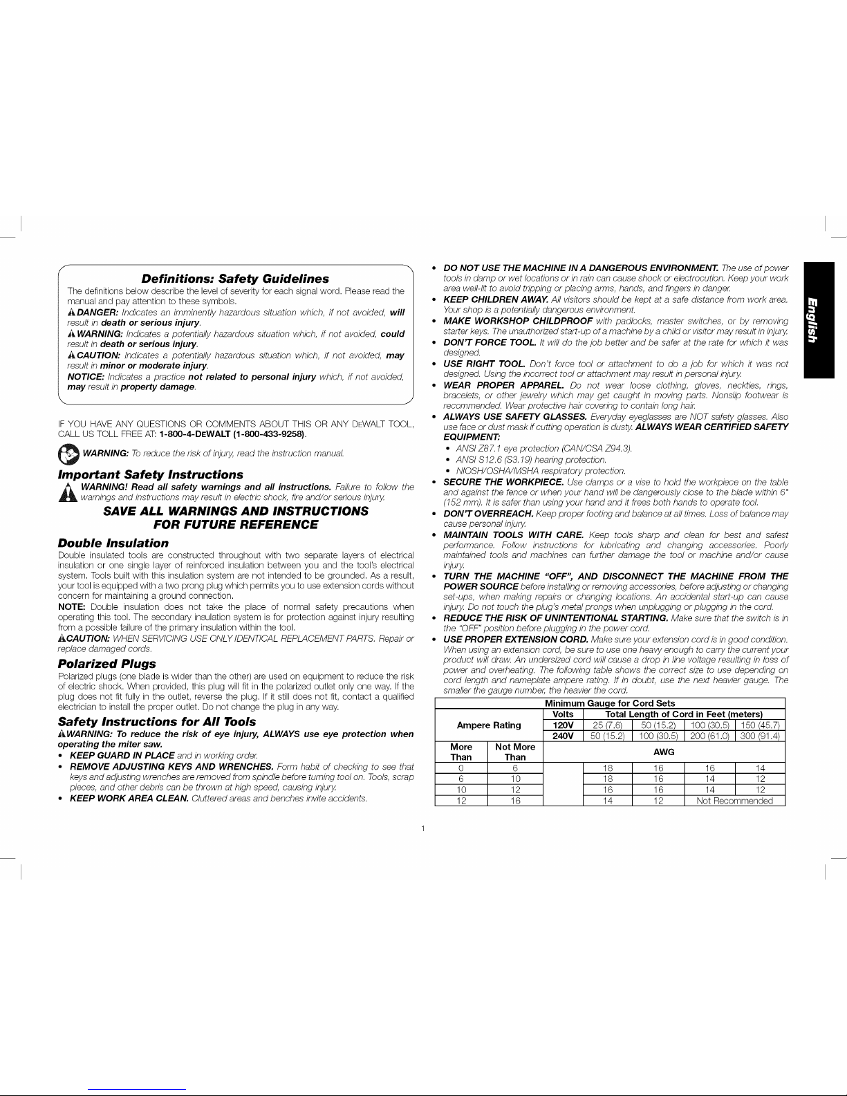
• USE PROPER EXTENSION CORD. Make sure your extension cord isin good condition.
When using an extension cord, be sure to use one heavy enough to carry the current your
product will draw. An undersized cord will cause a drop in line voltage resulting in loss of
power and overheating. The following table shows the correct size to use depending on
cord length and nameplate ampere rating. If in doubt, use the next heavier gauge. The
smaller the gauge number, the heavier the cord.
Minimum Gauge for Cord Sets
Volts Total Length of Cord in Feet (meters)
Ampere Rating 120V 25 (7.6) 50 (15.2) 100 (30.5) 150 (45.7)
240V 50 (15.2) 200 (61.0) 300 (91.4)
More
Than
0
6
10
12
Not More
Than
6
10
12
16
18
18
16
14
100 (30.5)
AWG
16
16
16
12
16 14
14 12
14 12
Not Recommended
Page 3
• CHECK FOR DAMAGED PARTS. Before further use of the tool, a guard or other part
that is damaged should be carefully checked to determine that it will operate properly and
perform its intended function--check for alignment of moving parts, binding of moving
parts, breakage of parts, mounting and any other conditions that may affect its operation.
A guard or otherpart that is damaged should be properly repaired or replaced. Do not use
tool if switch does not turn it on and off.
• USE RECOMMENDED ACCESSORIES. Use only accessories that are recommended
by the manufacturer for your model Accessories that may be suitable for one tool may be
hazardous when used on another tool Consult the instruction manual for recommended
accessories. The use of improper accessories may cause risk of injury to persons.
• NEVER STAND ON TOOL. Serious injury could occur if the tool is tipped or if the cutting
tool is unintentionally contacted.
• NEVER LEAVE TOOL RUNNING UNATTENDED. TURN POWER OFF. Don't leave
tool until it comes to a complete stop. Serious injury can result.
• DO NOT OPERATE ELECTRIC TOOLS NEAR FLAMMABLE LIQUIDS OR IN
GASEOUS OR EXPLOSIVE ATMOSPHERES. Motors in these tools may spark and
ignite fumes.
• STAY ALERT, WATCH WHAT YOU ARE DOING, AND USE COMMON SENSE. DO
NOT USE THE MACHINE WHEN YOU ARE TIRED OR UNDER THE INFLUENCE
OF DRUGS OR ALCOHOL. A moment of inattention while operating power tools may
result in injury.
Additional Safety Rules For Miter Saws
WARNING: Do not allow familiarity (gained from frequent use of your saw) to replace safety
rules.Always remember that a careless fraction of a second is sufficient to inflict severe injury.
• DO NOT OPERATE THIS MACHINE until it is completely assembled and installed
according to the instructions. A machine incorrectly assembled can cause serious injury.
• OBTAIN ADVICE from your supervisor, instructor, or another qualified person if you are
not thoroughly familiar with the operation of this machine. Knowledge is safety.
• STABILITY. Make sure the miter saw is placed on a secure supporting surface and does
not slip or move during use.
• FOLLOW ALL WIRING CODES and recommended electrical connections to prevent
shock or electrocution. Protect electric supply line with at least a 15 ampere time-delay
fuse or a circuit breaker.
• MAKE CERTAIN the blade rotates in the correct direction. The teeth on the blade should
point in the direction of rotation as marked on the saw.
• TIGHTEN ALL CLAMP HANDLES, knobs and levers prior to operation. Loose clamps
can cause parts or the workpiece to be thrown at high speeds.
• BE SURE all blade and blade clamps are clean, recessed sides of blade clamps are
against blade and arbor screw is tightened securely. Loose or improper blade clamping
may result in damage to the saw and possible personal injury.
• ALWAYS USE A SHARP BLADE. Check the blade to see if it runs true and is free from
vibration. A dull or a vibrating blade can cause damage to the machine and/or serious
injury.
• DO NOT OPERATE ON ANYTHING OTHER THAN THE DESIGNATED VOLTAGE for
the saw. Overheating, damage to the tool and personal injury may occur.
• DO NOT WEDGE ANYTHING AGAINST THE FAN to hold the motor shaft. Damage to
tool and possible personal injury may occur.
• DO NOT FORCE CUTTING ACTION. Stalling or partial stalling of motor can cause
damage to the machine or blade and/or serious injury.
• ALLOW THE MOTOR TO COME TO FULL SPEED priorto starting cut. Starting the cut
too soon may cause damage to the machine or blade and/or serious injury.
• NEVER CUT FERROUS METALS (those with any iron or steel content) or masonry.
Either of these can cause the carbide tips to flyoff the blade at high speeds causing serious
injury.
• DO NOTUSEABRASIVE WHEELS. The excessive heat and abrasive particles generated
by them may damage the saw and cause personal injury.
• NEVER HAVE ANY PART OF YOUR BODY IN LINE WITH THE PATH OF THE SAW
BLADE. Personal injury will occur.
• NEVER APPLY BLADE LUBRICANT TO A RUNNING BLADE. Applying lubricant could
cause your hand to move into the blade resulting in serious injury.
• DO NOT place either hand in the blade area when the saw is connected to the power
source. Inadvertent blade activation may result in serious injury.
• DO NOT PERFORM FREEHAND OPERATIONS (workpiece not supported by table and
fence). Hold the work firmly against the fence and table. Freehand operations on a miter
saw could cause the workpiece to be thrown at high speeds, causing serious injury.
• NEVER REACH AROUND OR BEHIND THE SAW BLADE. A blade can cause serious
injury.
• DO NOT REACH UNDERNEATH THE SAW unless it is unplugged and turned off.
Contact with saw blade may cause personal injury.
• SECURE THE MACHINE TO A STABLE SUPPORTING SURFACE. Vibration can
possibly cause the machine to slide, walk, or tip over, causing serious injury.
• USE ONLY CROSSCUT SAW BLADES recommended for miter saws. For best results,
do not use carbide tipped blades with hook angles in excess of 7 degrees. Do not use
blades with deep gullets. These can deflect and contact the guard, and can cause damage
to the machine and/or serious injury.
• USE ONLY BLADES OF THE CORRECT SIZE AND TYPE specified for this tool to
prevent damage to the machine and/or serious injury.
• INSPECT BLADE FOR CRACKS or other damage prior to operation. A cracked or
damaged blade can come apart and pieces can be thrown at high speeds, causing serious
injury. Replace cracked or damaged blades immediately.
• CLEAN THE BLADE AND BLADE CLAMPS prior to operation. Cleaning the blade
and blade clamps allows you to check for any damage to the blade or blade clamps. A
cracked or damaged blade or blade clamp can come apart and pieces can be thrown at
high speeds, causing serious injury.
• DO NOT use lubricants or cleaners (particularly spray or aerosol) in the vicinity of the
plastic guard. The polycarbonate material used in the guard is subject to attack by certain
chemicals.
• ALWAYS USE THE KERF PLATE AND REPLACE THIS PLATE WHEN DAMAGED.
Small chip accumulation under the saw may interfere with the saw blade or may cause
instability of workpiece when cutting.
• USE ONLY BLADE CLAMPS SPECIFIED FOR THIS TOOL to prevent damage to the
machine and/or serious injury.
• CLEAN THE MOTOR AIR SLOTS of chips and sawdust. Clogged motor air slots can
cause the machine to overheat, damaging the machine and possibly causing a short which
could cause serious injury.
• KEEP ARMS, HANDS, AND FINGERS AWAY FROM THE BLADE to prevent severe
cuts. Clamp all workpieces that would cause your hand to be within 6" (152 mm) of the
saw blade.
• NEVER LOCK THE SWITCH IN THE "ON" POSITION. Severe personal injury may
result.
• TURN OFF THE MACHINE and allow the blade to come to a complete stop before
raising the arm and prior to cleaning the blade area, removing debris in the path of the
blade, before servicing or adjusting tool A moving blade can cause serious injury.
Page 4
• PROPERLY SUPPORT LONG OR WIDE WORKPIECES. Loss of control of the
workpiece can cause injury.
• NEVER CROSS ARMS IN FRONT OF BLADE while using tool Always make a dry run
(unpowered) before making a finish cut so that you can check the path of the blade or
severe personal injury may result.
• ADDITIONAL INFORMATION regarding the safe and proper operation of power tools
(i.e., a safety video) is available from the Power Tool Institute, 1300 Sumner Avenue,
Cleveland, OH 44115-2851 (www.powertoolinstitute.com). Information is also available
from the National Safety Council, 1121 Spring Lake Drive, Itasca, IL 60143-3201. Please
refer to the American National Standards Institute ANSI 01.1 Safety Requirements for
Woodworking Machines and the U.S. Department of Labor OSHA 1910.213 Regulations.
_WARNING: Do not connect unit to electrical power source until complete instructions are
read and understood.
AWARNING: Always wear proper personal hearing protection that conforms to ANSI
$12.6 ($3.19) during use. Under some conditions and duration of use, noise from this
product may contribute to hearing loss.
J_,WARNING: NEVER MAKE ANY CUT UNLESS THE MATERIAL IS SECURED ON THE
TABLEAND AGAINST THE FENCE.
_WARNING: Some dust created by power sanding, sawing, grinding, drilling, and other
construction activities contains chemicals known to the State of California to cause cancer,
birth defects or other reproductive harm. Some examples of these chemicals are:
• lead from lead-based paints,
• crystalline silica from bricks and cement and other masonry products, and
• arsenic and chromium from chemically-treated lumber.
Your risk from these exposures varies, depending on how often you do this type of work.
To reduce your exposure to these chemicals: work in a well ventilated area, and work with
approved safety equipment, such as those dust masks that are specially designed to filter out
microscopic particles.
• Avoid prolonged contact with dust from power sanding, sawing, grinding, drilling,
and other construction activities. Wear protective clothing and wash exposed
areas with soap and water. Allowing dust to get into your mouth, eyes, or lay on
the skin may promote absorption of harmful chemicals.
,_ WARNING: Use of this tool can generate and/or disperse dust, which may cause serious
and permanent respiratory or other injury. Always use NIOSH/OSHA approved respiratory
protection appropriate for the dust exposure. Direct particles away from face and body.
For your convenience and safety, the following warning labels are on your miter saw.
ON MOTOR HOUSING:
_ WARNING: FOR YOUR OWN SAFETY, READ INSTRUCTION MANUAL BEFORE
OPERATING MITER SAW.
WHEN SERVICING, USE ONLY IDENTICAL REPLACEMENT PARTS.
DO NOT EXPOSE TO RAIN OR USE IN DAMP LOCATIONS.
ALWAYS USE PROPER EYE AND RESPIRATORY PROTECTION.
ON MOVING FENCES:
ALWAYS ADJUST FENCE
PROPERLY BEFORE USE. CLAMP
SMALL PIECES BEFORE CUTTING.
SEE MANUAL.
ALWAYSADJUST FENCEPROPERLYBEFOREUSE.
CLAMPSMALL PIECESBEFORECUTTING.SEEMANUAL
AJUSTE LAGUiA DEOJDAMENTEANTES DEUTILJSARLA
RERRAMIENTA. ASEGURELASPiEZAS PEQUENASANTES DE
CORTARLAS.CONSULTEELMANUAL
TOUJOURSRIEGLERLEGUIDE AVANTL'UTiLiSATION. FIXERLES
PETiTS DOJETSAVANT DE LESSCiER,CONSULTERLE GUIDE
D'UTILJSATION, j
ON GUARD:
DANGER-KEEP AWAY FROM BLADE.
ON UPPER GUARD:
PROPERLY SECURE BRACKET WITH BOTH SCREWS BEFORE
USE.
KEEP AWAY
FROM BLADE
MANTENERS ALEJADO
DE LA HOJA
S'ELOIBNER DE LA LAME
ON TABLE: (2 PLACES)
J_WARNING: FOR YOUR OWN SAFETY, READ INSTRUCTION
MANUAL BEFORE OPERATING MITER SAW. KEEP HANDS
OUT OF PATH OF SAW BLADE. DO NOT OPERATE SAW
WITHOUT GUARDS IN PLACE. CHECK LOWER GUARD FOR
PROPER CLOSING BEFORE EACH USE. ALWAYS TIGHTEN
ADJUSTMENT KNOBS BEFORE USE. DO NOT PERFORM ANY
OPERATION FREEHAND. NEVER REACH IN BACK OF SAW BLADE. NEVER
CROSS ARMS IN FRONT OF BLADE. TURN OFF TOOL AND WAlT FOR SAW
BLADE TO STOP BEFORE MOVING WORKPIECE, CHANGING SETTINGS OR
MOVING HANDS. DISCONNECT POWER BEFORE CHANGING BLADE OR
SERVICING. TO REDUCE THE RISK OF INJURY, RETURN CARRIAGE TO THE
FULL REAR POSITION AFTER EACH CROSSCUT OPERATION. THINK! YOU CAN
PREVENT ACCIDENTS.
ON BASE: (2 PLACES)
Electrical Connection
Be sure your power supply agrees with the nameplate marking. 120 volts, AC means that your
saw will operate on alternating current. The switch is susceptible to failure if direct current is
used. A voltage decrease of 10 percent or more will cause a loss of power and overheating.
All DEWALT tools are factory tested. If this tool does not operate, check the power supply.
Accessories
AWARNING: Since accessories, other than those offered by DEWALT,have not been tested
with this product, use of such accessories with this tool could be hazardous. To reduce the
risk of injury, only DEWALT recommended accessories should be used with this product.
Recommended accessories for use with your tool are available for purchase from your local
dealer or authorized service center. If you need assistance in locating any accessory for your
tool, please contact DEWALT Industrial Tool Co., 701 East Joppa Road, Towson, MD 21286,
call 1-800-4-DEWALT (1-800-433-9258) or visit our website: www.dewalt.com.
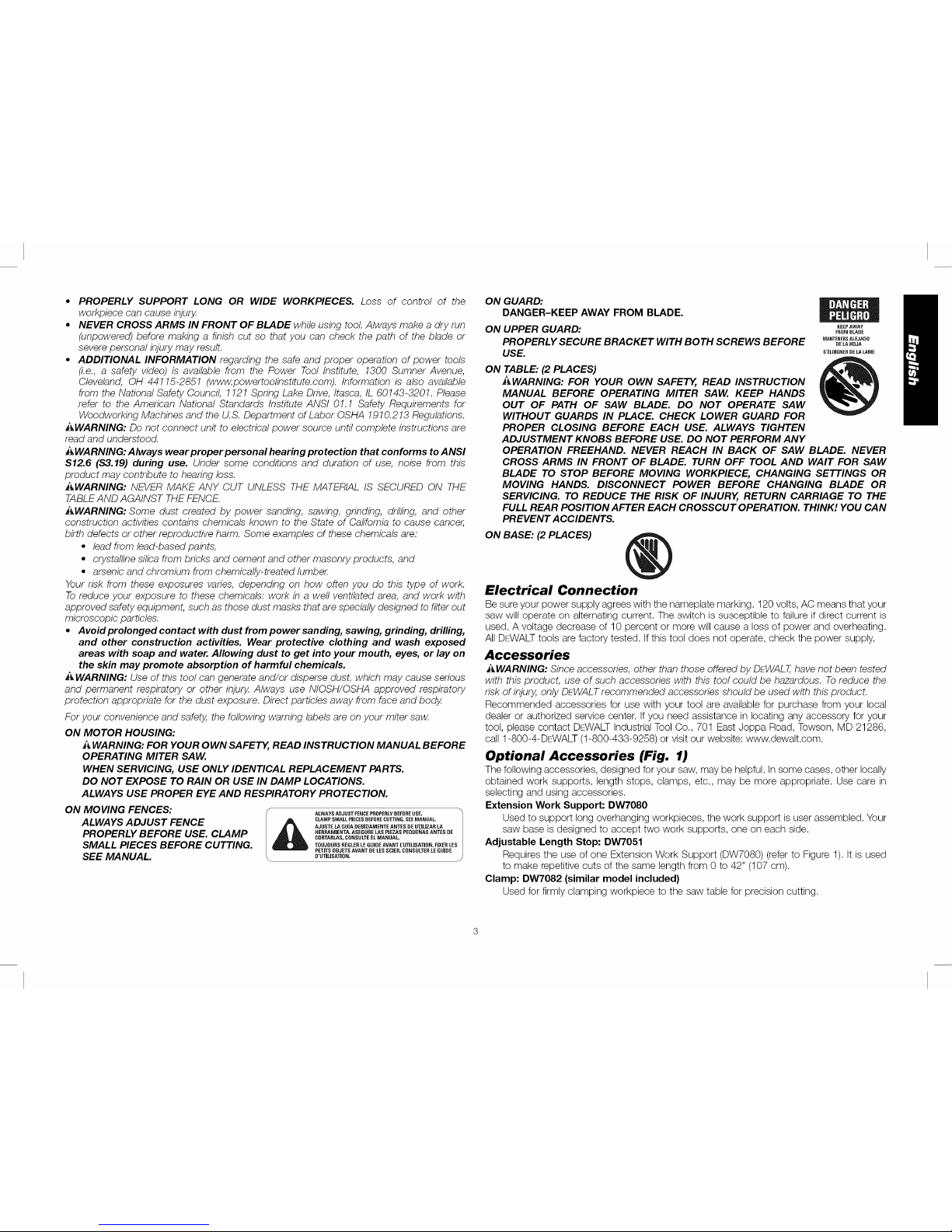
Optional Accessories (Fig. 1)
The following accessories, designed for your saw, may be helpful. In some cases, other locally
obtained work supports, length stops, clamps, etc., may be more appropriate. Use care in
selecting and using accessories.
Extension Work Support: DW7080
Used to support long overhanging workpieces, the work support is user assembled. Your
saw base is designed to accept two work supports, one on each side.
Adjustable Length Stop: DW7051
Requires the use of one Extension Work Support (DW7080) (refer to Figure 1). It is used
to make repetitive cuts of the same length from 0 to 42" (107 cm).
Clamp: DW7082 (similar model included)
Used for firmly clamping workpiece to the saw table for precision cutting
Page 5
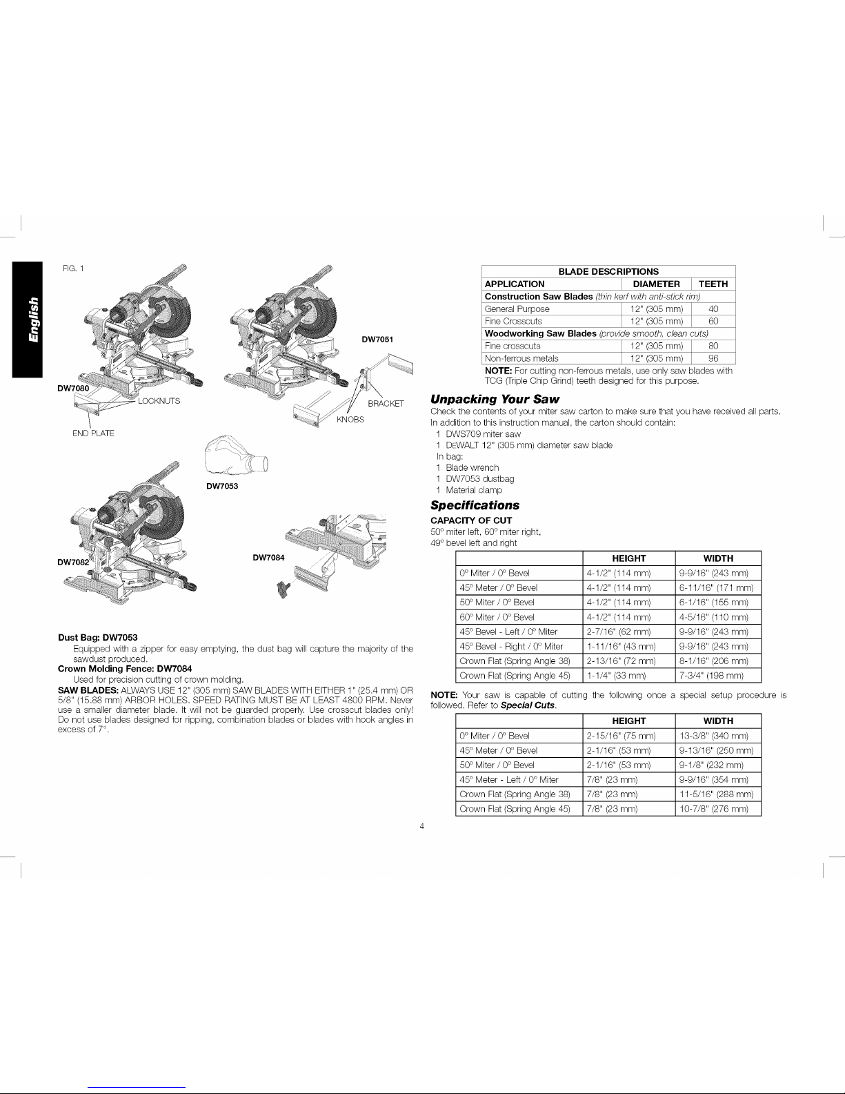
FIG. 1
END PLATE
LOCKNUTS
DW7051
BRACKET
KNOBS
DW7053
Dust Bag: DW7053
Equipped with a zipper for easy emptying, the dust bag will capture the majority of the
sawdust produced.
Crown Molding Fence: DW7084
Used for precision cutting of crown molding.
SAW BLADES: ALWAYS USE 12" (305 mm) SAW BLADES WITH EITHER 1" (25.4 mm) OR
5/8" (15.88 mm) ARBOR HOLES. SPEED RATING MUST BE AT LEAST 4800 RPM. Never
use a smaller diameter blade. It will not be guarded properly. Use crosscut blades only!
Do not use blades designed for ripping, combination blades or blades with hook angles in
excess of 7°.
BLADE DESCRIPTIONS
APPLICATION DIAMETER ] TEETH
Construction Saw Blades (thin kerr with anti-stick rim)
General Purpose 12" (305 mm) I 40
Fine Crosscuts 12" (305 mm) _ 60
Woodworking Saw Blades (provide smooth, clean cuts)
Fine crosscuts 12" (305 mm) I 80
Non-ferrous metals 12" (305 mm) _ 96
NOTE: For cutting non-ferrous metals, use only saw blades with
TCG (TripleChip Grind) teeth designed for this purpose.
Unpacking Your Saw
Check the contents of your miter saw carton to make sure that you have received all parts.
Inaddition to this instruction manual, the carton should contain:
1 DWS709 miter saw
1 DEWALT 12" (305 mm) diameter saw blade
In bag:
1 Blade wrench
1 DW7053 dustbag
1 Material clamp
Specifications
CAPACITY OF CUT
50° miter left, 60° miter right,
49° bevel left and right
HEIGHT WIDTH
0° Miter / 0° Bevel 4-1/2" (114 mm) 9-9/16" (243 mm)
45° Meter / 0° Bevel 4-1/2" (114 mm) 6-11/16" (171 mm)
50° Miter / 0° Bevel 4-1/2" (114 mm) 6-1/16" (155 mm)
60° Miter / 0° Bevel 4-1/2" (114 mm) 4-5/16" (110 mm)
45° Bevel - Left / 0° Miter 2-7/16" (62 mm) 9-9/16" (243 mm)
45° Bevel - Right / 0° Miter 1-11/16" (43 mm) 9-9/16" (243 mm)
Crown Flat (Spring Angle 38) 2-13/16" (72 mm) 8-1/16" (206 mm)
Crown Flat (Spring Angle 45) 1-1/4" (33 mm) 7-3/4" (198 mm)
NOTE: Your saw is capable of cutting the following once a special setup procedure is
followed. Refer to Special Cuts.
HEIGHT WIDTH
0° Miter / 0° Bevel 2-15/16" (75 mm) 13-3/8" (340 mm)
45° Meter / 0° Bevel 2-1/16" (53 mm) 9-13/16" (250 mm)
50° Miter / 0° Bevel 2-1/16" (53 mm) 9-1/8" (232 mm)
45° Meter - Left / 0° Miter 7/8" (23 mm) 9-9/16" (354 mm)
Crown Flat (Spring Angle 38) 7/8" (23 mm) 11-5/16" (288 mm)
Crown Flat (Spring Angle 45) 7/8" (23 mm) 10-7/8" (276 mm)
Page 6
DRIVE
120 V motor
1600 watts in 15 amp motor
3800 RPM Cut helical gears
Multi-V belt Roller bearings
Automatic electric brake Carbide blade
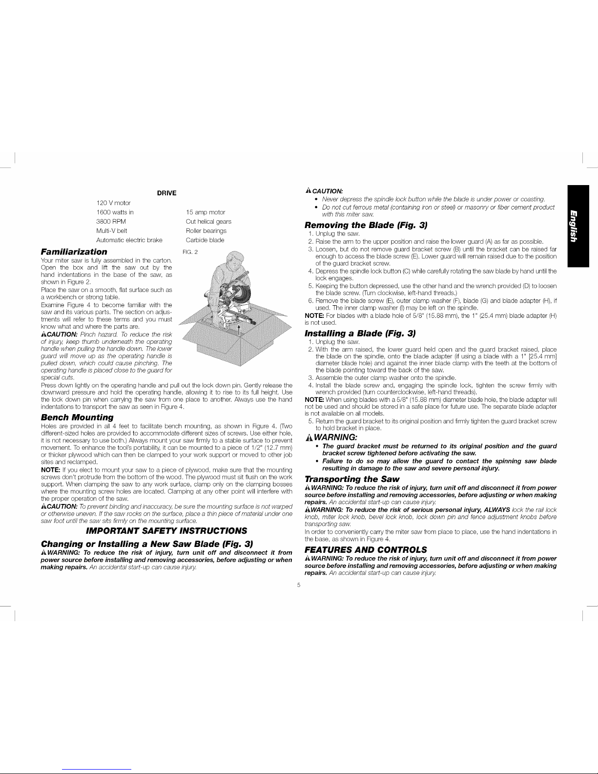
Familiarization FIG.2
Your miter saw is fully assembled in the carton.
Open the box and lift the saw out by the
hand indentations in the base of the saw, as
shown in Figure 2.
Place the saw on a smooth, flat surface such as
a workbench or strong table.
Examine Figure 4 to become familiar with the
saw and its various parts. The section on adjus-
tments will refer to these terms and you must
know what and where the parts are.
i_CAUTION: Pinch hazard. To reduce the risk
of injury, keep thumb underneath the operating
handle when pulling the handle down. The lower
guard will move up as the operating handle is
pulled down, which could cause pinching. The
operating handle is placed close to the guard for
special cuts.
Press down lightly on the operating handle and pull out the lock down pin. Gently release the
downward pressure and hold the operating handle, allowing it to rise to its full height. Use
the lock down pin when carrying the saw from one place to another. Always use the hand
indentations to transport the saw as seen in Figure 4.
Bench Mounting
Holes are provided in all 4 feet to facilitate bench mounting, as shown in Figure 4. (Two
different-sized holes are provided to accommodate different sizes of screws. Use either hole,
it is not necessary to use both.) Always mount your saw firmly to a stable surface to prevent
movement. To enhance the tool's portability, it can be mounted to a piece of 1/2" (12.7 mm)
or thicker plywood which can then be clamped to your work support or moved to other job
sites and reclamped.
NOTE: If you elect to mount your saw to a piece of plywood, make sure that the mounting
screws don't protrude from the bottom of the wood. The plywood must sit flush on the work
support. When clamping the saw to any work surface, clamp only on the clamping bosses
where the mounting screw holes are located. Clamping at any other point will interfere with
the proper operation of the saw.
i_CAUTION: Toprevent binding and inaccuracy, be sure the mounting surface is not warped
or otherwise uneven. If the saw rocks on the surface, place a thin piece of material under one
saw foot until the saw sits firmly on the mounting surface.
IMPORTANT SAFETY INSTRUCTIONS
Changing or Installing a New Saw Blade (Fig. 3)
i_ WARNING: To reduce the risk of injury, turn unit off and disconnect it from
power source before installing and removing accessories, before adjusting or when
making repairs. An accidental start-up can cause injury,
A CAUTION:
• Never depress the spindle lock button while the blade is under power or coasting.
• Do not cut ferrous metal (containing iron or steel) or masonry or fiber cement product
with this miter saw.
Removing the Blade (Fig. 3)
1. Unplug the saw.
2. Raise the arm to the upper position and raise the lower guard (A) as far as possible.
3. Loosen, but do not remove guard bracket screw (B) until the bracket can be raised far
enough to access the blade screw (E).Lower guard will remain raised due to the position
of the guard bracket screw.
4. Depress the spindle lock button (C)while carefully rotating the saw blade by hand until the
lock engages.
5. Keeping the button depressed, use the other hand and the wrench provided (D) to loosen
the blade screw. (Turn clockwise, left-hand threads.)
6. Remove the blade screw (E),outer clamp washer (F), blade (G) and blade adapter (H), if
used. The inner clamp washer (I) may be left on the spindle.
NOTE: For blades with a blade hole of 5/8" (15.88 mm), the 1" (25.4 mm) blade adapter (H)
is not used.
Installing a Blade (Fig. 3)
1. Unplug the saw.
2. With the arm raised, the lower guard held open and the guard bracket raised, place
the blade on the spindle, onto the blade adapter (if using a blade with a 1" [25.4 mm]
diameter blade hole) and against the inner blade clamp with the teeth at the bottom of
the blade pointing toward the back of the saw.
3. Assemble the outer clamp washer onto the spindle.
4. Install the blade screw and, engaging the spindle lock, tighten the screw firmly with
wrench provided (turn counterclockwise, left-hand threads).
NOTE: When using blades with a 5/8" (15.88 mm) diameter blade hole, the blade adapter will
not be used and should be stored in a safe place for future use. The separate blade adapter
is not available on all models.
5. Return the guard bracket to its original position and firmly tighten the guard bracket screw
to hold bracket in place.
WARNING:
• The guard bracket must be returned to its original position and the guard
bracket screw tightened before activating the saw.
• Failure to do so may allow the guard to contact the spinning saw blade
resulting in damage to the saw and severe personal injury.
Transporting the Saw
A WARNING: To reduce the risk of injury, turn unit off and disconnect it from power
source before installing and removing accessories, before adjusting or when making
repairs. An accidental start-up can cause injury,
_WARNING: To reduce the risk of serious personal injury, ALWAYS lock the raftlock
knob, miter lock knob, bevel lock knob, lock down pin and fence adjustment knobs before
transporting saw.
Inorder to conveniently carry the miter saw from place to place, use the hand indentations in
the base, as shown in Figure 4.
FEATURES AND CONTROLS
A WARNING: To reduce the risk of injury, turn unit off and disconnect it from power
source before installing and removing accessories, before adjusting or when making
repairs. An accidental start-up can cause injury,
Page 7
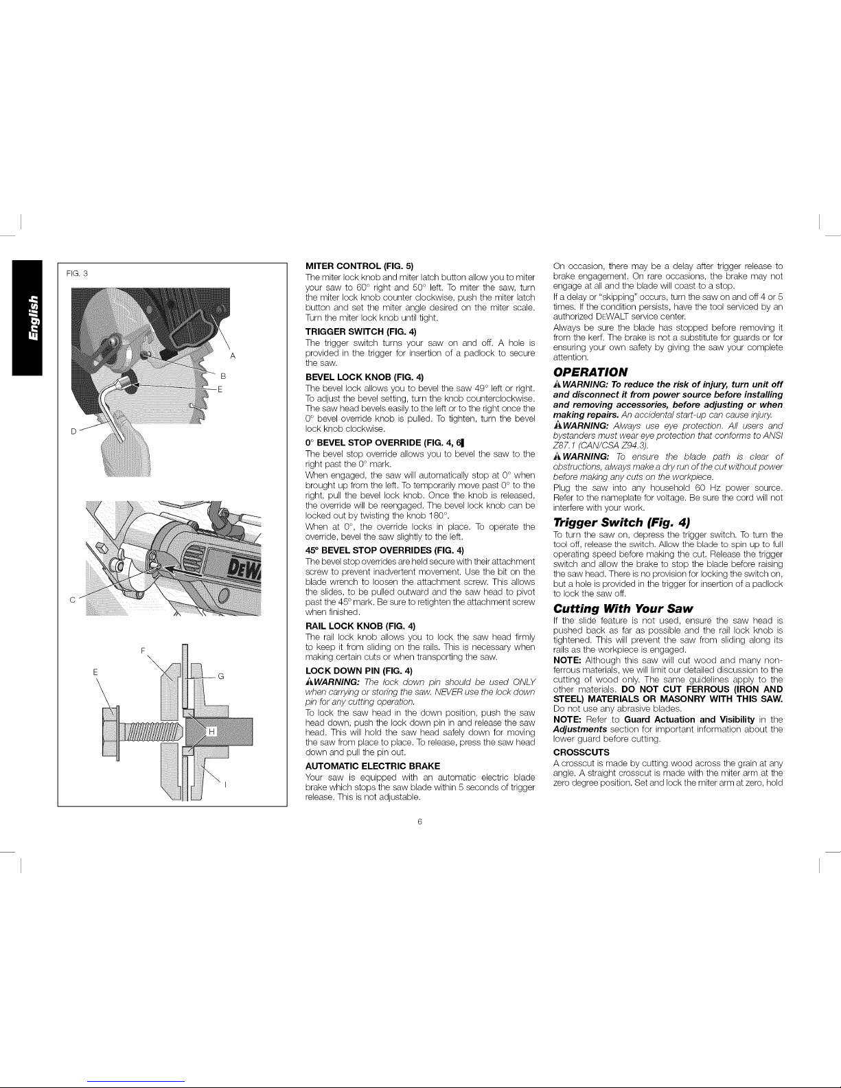
FIG. 3
A
B
MITER CONTROL (FIG. 5)
The miter lock knob and miter latch button allow you to miter
your saw to 60° right and 50 ° left. To miter the saw, turn
the miter lock knob counter clockwise, push the miter latch
button and set the miter angle desired on the miter scale.
Turn the miter lock knob until tight.
TRIGGER SWITCH (FIG. 4}
The trigger switch turns your saw on and off. A hole is
provided in the trigger for insertion of a padlock to secure
the saw.
BEVEL LOCK KNOB (FIG. 4)
The bevel lock allows you to bevel the saw 49 ° left or right.
Toadjust the bevel setting, turn the knob counterclockwise.
The saw head bevels easily to the left or to the right once the
0° bevel override knob is pulled. To tighten, turn the bevel
lock knob clockwise.
0° BEVEL STOP OVERRIDE (FIG. 4, 61
The bevel stop override allows you to bevel the saw to the
right past the 0° mark.
When engaged, the saw will automatically stop at 0 ° when
brought up from the left. To temporarily move past 0° to the
right, pull the bevel lock knob. Once the knob is released,
the override will be reengaged. The bevel lock knob can be
locked out by twisting the knob 180°.
When at 0°, the override locks in place. To operate the
override, bevel the saw slightly to the left.
45° BEVEL STOP OVERRIDES (FIG. 4}
The bevel stop overrides are held secure with their attachment
screw to prevent inadvertent movement. Use the bit on the
blade wrench to loosen the attachment screw. This allows
the slides, to be pulled outward and the saw head to pivot
past the 45° mark. Be sure to retighten the attachment screw
when finished.
RAIL LOCK KNOB (FIG. 4)
The rail lock knob allows you to lock the saw head firmly
to keep it from sliding on the rails. This is necessary when
making certain cuts or when transporting the saw.
LOCK DOWN PIN (FIG. 4}
i_WARNING: The lock down pin should be used ONLY
when carrying or storing the saw. NEVER use the lock down
pin for any cutting operation.
To lock the saw head in the down position, push the saw
head down, push the lock down pin in and release the saw
head. This will hold the saw head safely down for moving
the saw from place to place. To release, press the saw head
down and pull the pin out.
AUTOMATIC ELECTRIC BRAKE
Your saw is equipped with an automatic electric blade
brake which stops the saw blade within 5 seconds of trigger
release. This is not adjustable.
On occasion, there may be a delay after trigger release to
brake engagement. On rare occasions, the brake may not
engage at all and the blade will coast to a stop.
Ifa delay or "skipping" occurs, turn the saw on and off 4 or 5
times. If the condition persists, have the tool serviced by an
authorized DEWALT service center.
Always be sure the blade has stopped before removing it
from the kerf. The brake is not a substitute for guards or for
ensuring your own safety by giving the saw your complete
attention.
OPERATION
i_ WARNING: To reduce the risk of injury, turn unit off
and disconnect it from power source before installing
and removing accessories, before adjusting or when
making repairs. An accidental start-up can cause injury.
J_WARNING: Always use eye protection. All users and
bystanders must wear eye protection that conforms to ANSI
Z87.1 (CAN/CSA Z94.3).
h_WARNING: To ensure the blade path is clear of
obstructions, always make a dry run of the cut without power
before making any cuts on the workpiece.
Plug the saw into any household 60 Hz power source.
Refer to the nameplate for voltage. Be sure the cord will not
interfere with your work.
Trigger Switch (Fig. 4)
To turn the saw on, depress the trigger switch. To turn the
tool off, release the switch. Allow the blade to spin up to full
operating speed before making the cut. Release the trigger
switch and allow the brake to stop the blade before raising
the saw head. There is no provision for locking the switch on,
but a hole is provided in the trigger for insertion of a padlock
to lock the saw off.
Cutting With Your Saw
If the slide feature is not used, ensure the saw head is
pushed back as far as possible and the rail lock knob is
tightened. This will prevent the saw from sliding along its
rails as the workpiece is engaged.
NOTE: Although this saw will cut wood and many non-
ferrous materials, we will limit our detailed discussion to the
cutting of wood only. The same guidelines apply to the
other materials. DO NOT CUT FERROUS (IRON AND
STEEL) MATERIALS OR MASONRY WITH THIS SAW.
Do not use any abrasive blades.
NOTE: Refer to Guard Actuation and Visibility in the
Adjustments section for important information about the
lower guard before cutting.
CROSSCUTS
A crosscut is made by cutting wood across the grain at any
angle. A straight crosscut is made with the miter arm at the
zero degree position. Set and lock the miter arm at zero, hold
Page 8
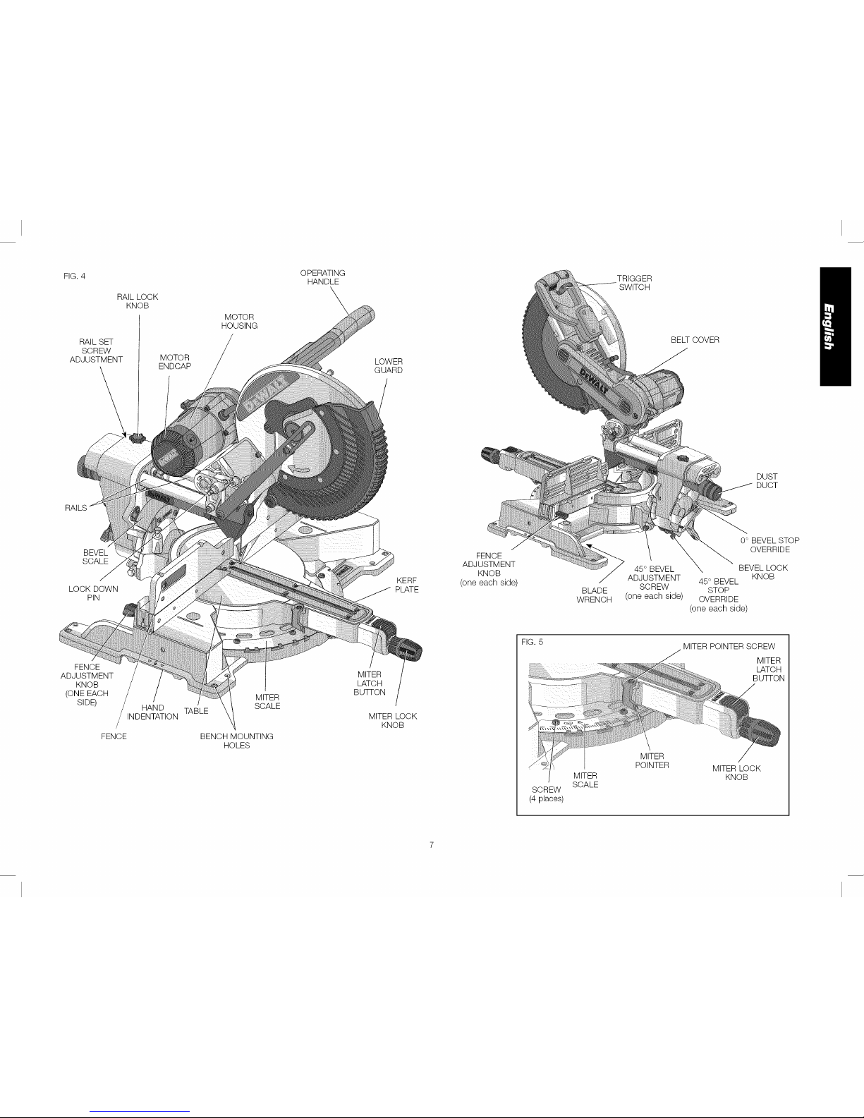
FIG. 4 TRIGGER
SWITCH
RAIL LOCK
KNOB
RAILSET
SCREW
ADJUSTMENT
MOTOR
ENDCAP
MOTOR
HOUSING
OPERATING
HANDLE
\
LOWER
GUARD
BELT COVER
DUST
DUCT
BEVEL
SCALE
LOCK DOWN
PIN
KERF
PLATE
FENCE
ADJUSTMENT
KNOB
(one each side)
BLADE
WRENCH
45 ° BEVEL
ADJUSTMENT
SCREW
(one each side)
0° BEVEL STOP
OVERRIDE
BEVEL LOCK
KNOB
45° BEVEL
STOP
OVERRIDE
(one each side)
FENCE
ADJUSTMENT
KNOB
(ONE EACH
SIDE)
FENCE
HAND
INDENTATION
MITER
SCALE
TABLE
BENCH MOUNTING
HOLES
MITER
LATCH
BUTI-ON
MITER LOCK
KNOB
FIG. 5
SCREW
(4 places)
MITER
SCALE
MITER
POINTER
MITER POINTER SCREW
MITER
LATCH
BUTI-ON
MITER LOCK
KNOB
Page 9
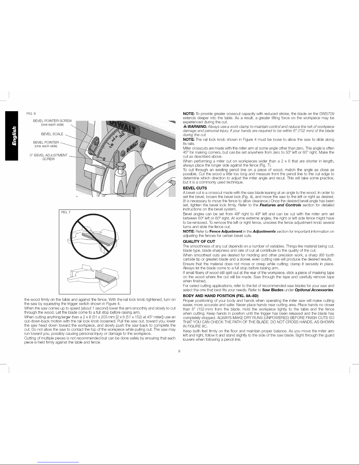
FIG.6
BEVELPOINTERSCREW
(oneeachside)
BEVELSCALE
BEVELPOINTER
(oneeachside)
0°BEVELADJUSTMENT
SCREW
FIG.7
the wood firmly on the table and against the fence. With the rail lock knob tightened, turn on
the saw by squeezing the trigger switch shown in Figure 4.
When the saw comes up to speed (about 1 second) lower the arm smoothly and slowly to cut
through the wood. Let the blade come to a full stop before raising arm.
When cutting anything larger than a 2 x 8 (51 x 203 mm [2 x 6 (51 x 152) at 45° miter]) use an
out-down-back motion with the rail lock knob loosened. Pull the saw out, toward you, lower
the saw head down toward the workpiece, and slowly push the saw back to complete the
cut. Do not allow the saw to contact the top of the workpiece while pulling out. The saw may
run toward you, possibly causing personal injury or damage to the workpiece.
Cutting of multiple pieces is not recommended but can be done safely by ensuring that each
piece is held firmly against the table and fence.
NOTE; To provide greater crosscut capacity with reduced stroke, the blade on the DWS709
extends deeper into the table. As a result, a greater lifting force on the workpiece may be
experienced during the cut.
A WARNING: Always use a work clamp to maintain control and reduce the risk of workpiece
damage and personal injury,if your hands are required to be within 6" (152 mm) of the blade
during the cut.
NOTE; The rail lock knob shown in Figure 4 must be loose to allow the saw to slide along
its rails.
Miter crosscuts are made with the miter arm at some angle other than zero. This angle is often
45° for making corners, but can be set anywhere from zero to 50° left or 60° right. Make the
cut as described above.
When performing a miter cut on workpieces wider than a 2 x 6 that are shorter in length,
always place the longer side against the fence (Fig. 7).
To cut through an existing pencil line on a piece of wood, match the angle as close as
possible. Cut the wood a little too long and measure from the pencil line to the cut edge to
determine which direction to adjust the miter angle and recut. This will take some practice,
but it is a commonly used technique.
BEVEL CUTS
A bevel cut is a crosscut made with the saw blade leaning at an angle to the wood. In order to
set the bevel, loosen the bevel lock (Fig. 4), and move the saw to the left or right as desired.
(It is necessary to move the fence to allow clearance.) Once the desired bevel angle has been
set, tighten the bevel lock firmly. Refer to the Features and Controls section for detailed
instructions on the bevel system.
Bevel angles can be set from 49° right to 49 ° left and can be cut with the miter arm set
between 50° left or 60° right. At some extreme angles, the right or left side fence might have
to be removed. To remove the left or right fence, unscrew the fence adjustment knob several
turns and slide the fence out.
NOTE: Refer to Fence Adjustment in the Adjustments section for important information on
adjusting the fences for certain bevel cuts.
QUALITY OF CUT
The smoothness of any cut depends on a number of variables. Things like material being cut,
blade type, blade sharpness and rate of cut all contribute to the quality of the cut.
When smoothest cuts are desired for molding and other precision work, a sharp (60 tooth
carbide tip or greater) blade and a slower, even cutting rate will produce the desired results.
Ensure that the material does not move or creep while cutting; clamp it securely in place.
Always let the blade come to a full stop before raising arm.
Ifsmall fibers of wood still split out at the rear of the workpiece, stick a piece of masking tape
on the wood where the cut will be made. Saw through the tape and carefully remove tape
when finished.
For varied cutting applications, refer to the list of recommended saw blades for your saw and
select the one that best fits your needs. Refer to Saw Blades under OptionalAccessories.
BODY AND HAND POSITION (FIG. 8A-8D)
Proper positioning of your body and hands when operating the miter saw will make cutting
easier, more accurate and safer. Never place hands near cutting area. Place hands no closer
than 6" (152 mm) from the blade. Hold the workpiece tightly to the table and the fence
when cutting. Keep hands in position until the trigger has been released and the blade has
completely stopped. ALWAYS MAKE DRY RUNS (UNPOWERED) BEFORE FINISH CUTS SO
THAT YOU CAN CHECK THE PATH OF THE BLADE. DO NOT CROSS HANDS, AS SHOWN
IN FIGURE 8C.
Keep both feet firmly on the floor and maintain proper balance. As you move the miter arm
left and right, follow it and stand slightly to the side of the saw blade. Sight through the guard
louvers when following a pencil line.
Page 10
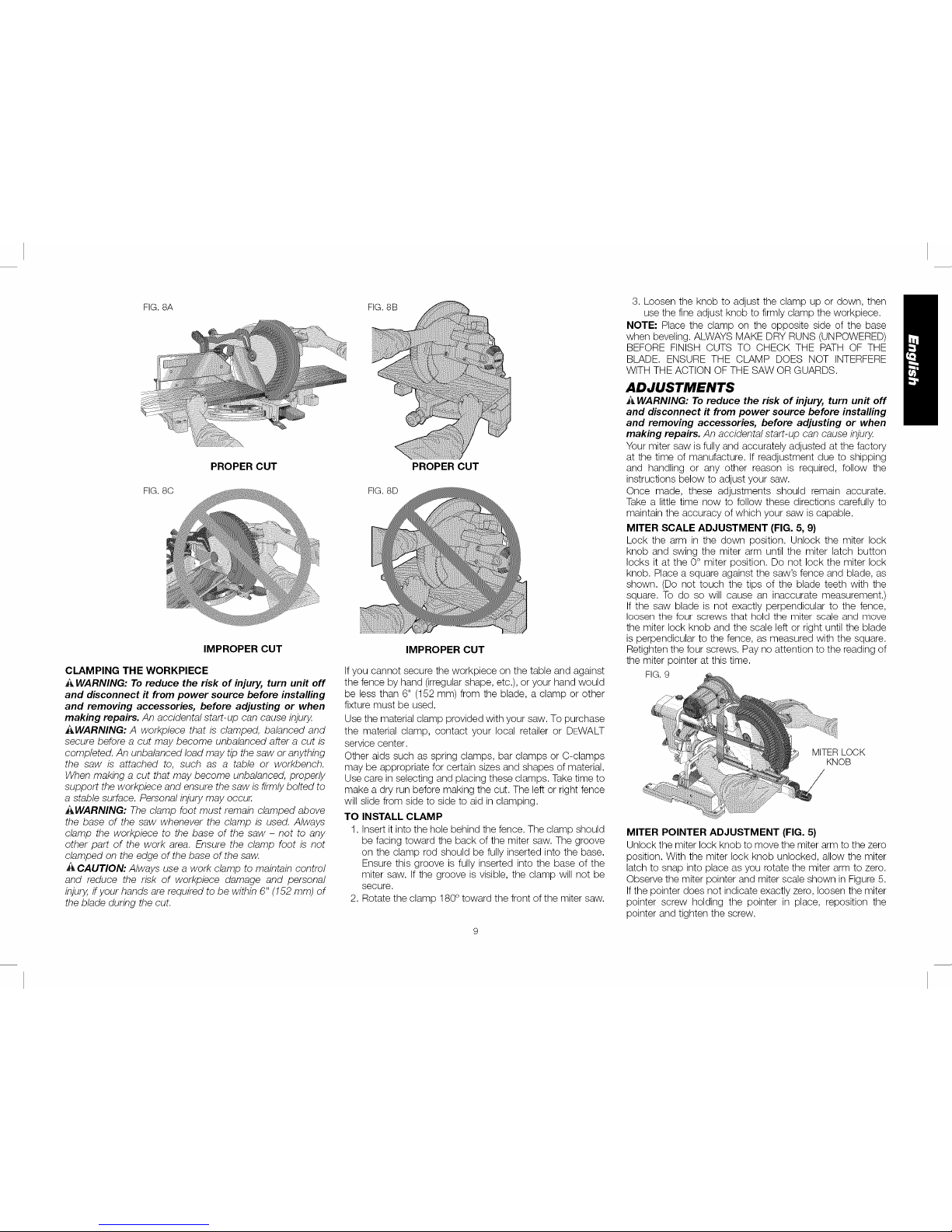
FIG. 8A
FIG. 8C
PROPER CUT
IMPROPER CUT
CLAMPING THE WORKPIECE
_ WARNING: To reduce the risk of injury, turn unit off
and disconnect ff from power source before installing
and removing accessories, before adjusting or when
making repairs. An accidental start-up can cause injury.
_,WARNING: A workpiece that is clamped, balanced and
secure before a cut may become unbalanced after a cut is
completed. An unbalanced load may tip the saw or anything
the saw is attached to, such as a table or workbench.
When making a cut that may become unbalanced, properly
support the workpiece and ensure the saw is firmly bolted to
a stable surface. Personal injury may occur.
_WARNING: The clamp foot must remain clamped above
the base of the saw whenever the clamp is used. Always
clamp the workpiece to the base of the saw - not to any
other part of the work area. Ensure the clamp foot is not
clamped on the edge of the base of the saw.
_ CAUTION: Always use a work clamp to maintain control
and reduce the risk of workpiece damage and personal
injury,if your hands are required to be within 6" (152 mm) of
the blade during the cut.
FIG. 8B
PROPER CUT
FIG.8D
IMPROPER CUT
Ifyou cannot secure the workpiece on the table and against
the fence by hand (irregular shape, etc.), or your hand would
be less than 6" (152 mm) from the blade, a clamp or other
fixture must be used.
Use the material clamp provided with your saw. To purchase
the material clamp, contact your local retailer or DEWALT
service center.
Other aids such as spring clamps, bar clamps or C-clamps
may be appropriate for certain sizes and shapes of material.
Use care in selecting and placing these clamps. Take time to
make a dry run before making the cut. The left or right fence
will slide from side to side to aid in clamping.
TO INSTALL CLAMP
1. Insert it into the hole behind the fence. The clamp should
be facing toward the back of the miter saw. The groove
on the clamp rod should be fully inserted into the base.
Ensure this groove is fully inserted into the base of the
miter saw. If the groove is visible, the clamp will not be
secure.
2. Rotate the clamp 180° toward the front of the miter saw.
3. Loosen the knob to adjust the clamp up or down, then
use the fine adjust knob to firmly clamp the workpiece.
NOTE" Place the clamp on the opposite side of the base
when beveling. ALWAYS MAKE DRY RUNS (UNPOWERED)
BEFORE FINISH CUTS TO CHECK THE PATH OF THE
BLADE. ENSURE THE CLAMP DOES NOT INTERFERE
WITH THE ACTION OF THE SAW OR GUARDS.
ADJUSTMENTS
A WARNING: To reduce the risk of injury, turn unit off
and disconnect ff from power source before installing
and removing accessories, before adjusting or when
making repairs. An accidental start-up can cause injury.
Your miter saw is fully and accurately adjusted at the factory
at the time of manufacture. If readjustment due to shipping
and handling or any other reason is required, follow the
instructions below to adjust your saw.
Once made, these adjustments should remain accurate.
Take a little time now to follow these directions carefully to
maintain the accuracy of which your saw is capable.
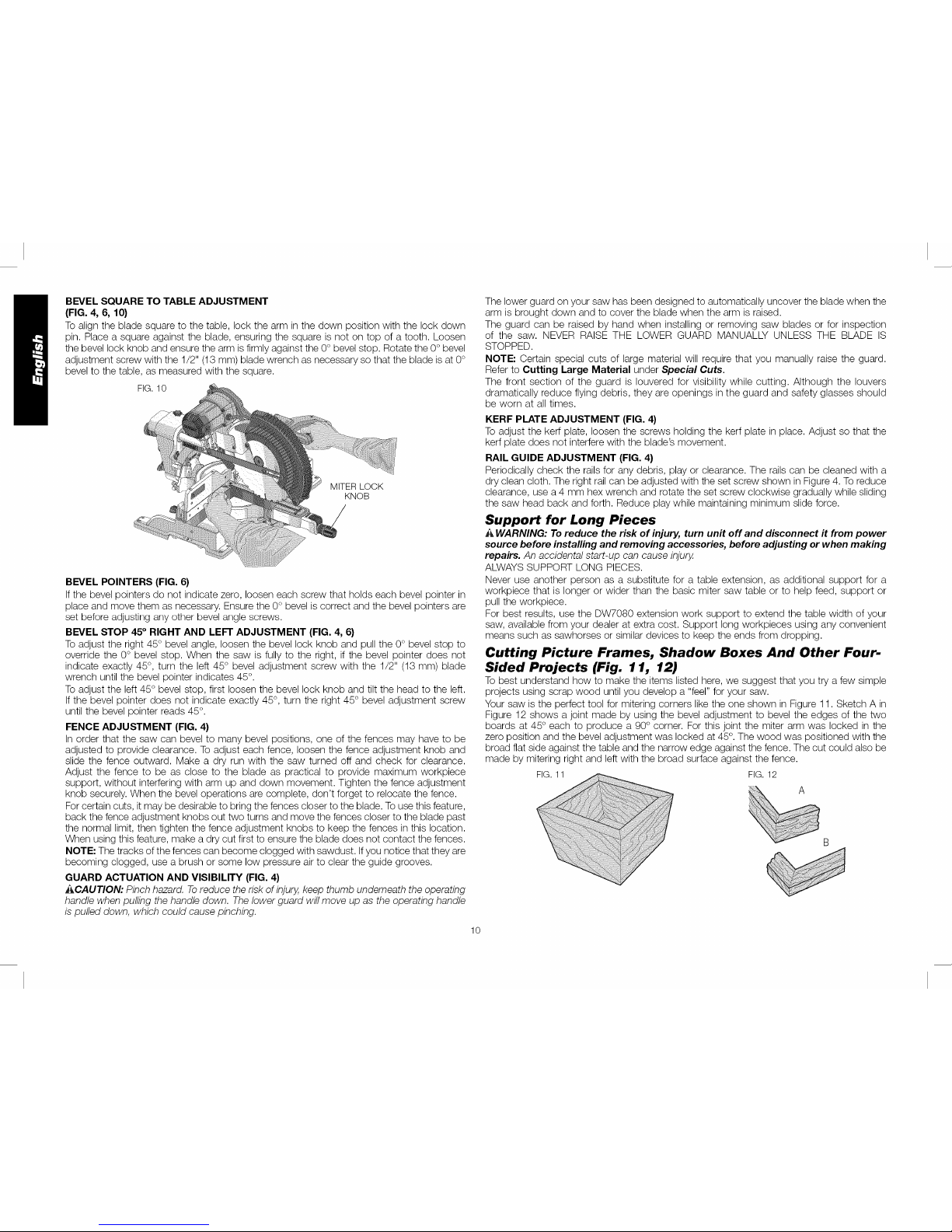
MITER SCALE ADJUSTMENT (FIG. 5, 9)
Lock the arm in the down position. Unlock the miter lock
knob and swing the miter arm until the miter latch button
locks it at the 0° miter position. Do not lock the miter lock
knob. Place a square against the saw's fence and blade, as
shown. (Do not touch the tips of the blade teeth with the
square. To do so will cause an inaccurate measurement.)
If the saw blade is not exactly perpendicular to the fence,
loosen the four- screws that hold the miter scale and move
the miter lock knob and the scale left or right until the blade
is perpendicular to the fence, as measured with the square.
Retighten the four screws. Pay no attention to the reading of
the miter pointer at this time.
FIG. 9
MITER LOCK
KNOB
MITER POINTER ADJUSTMENT (FIG. 5)
Unlock the miter lock knob to move the miter arm to the zero
position. With the miter lock knob unlocked, allow the miter
latch to snap into place as you rotate the miter arm to zero.
Observe the miter pointer and miter scale shown in Figure 5.
Ifthe pointer does not indicate exactly zero, loosen the miter
pointer screw holding the pointer in place, reposition the
pointer and tighten the screw.
Page 11
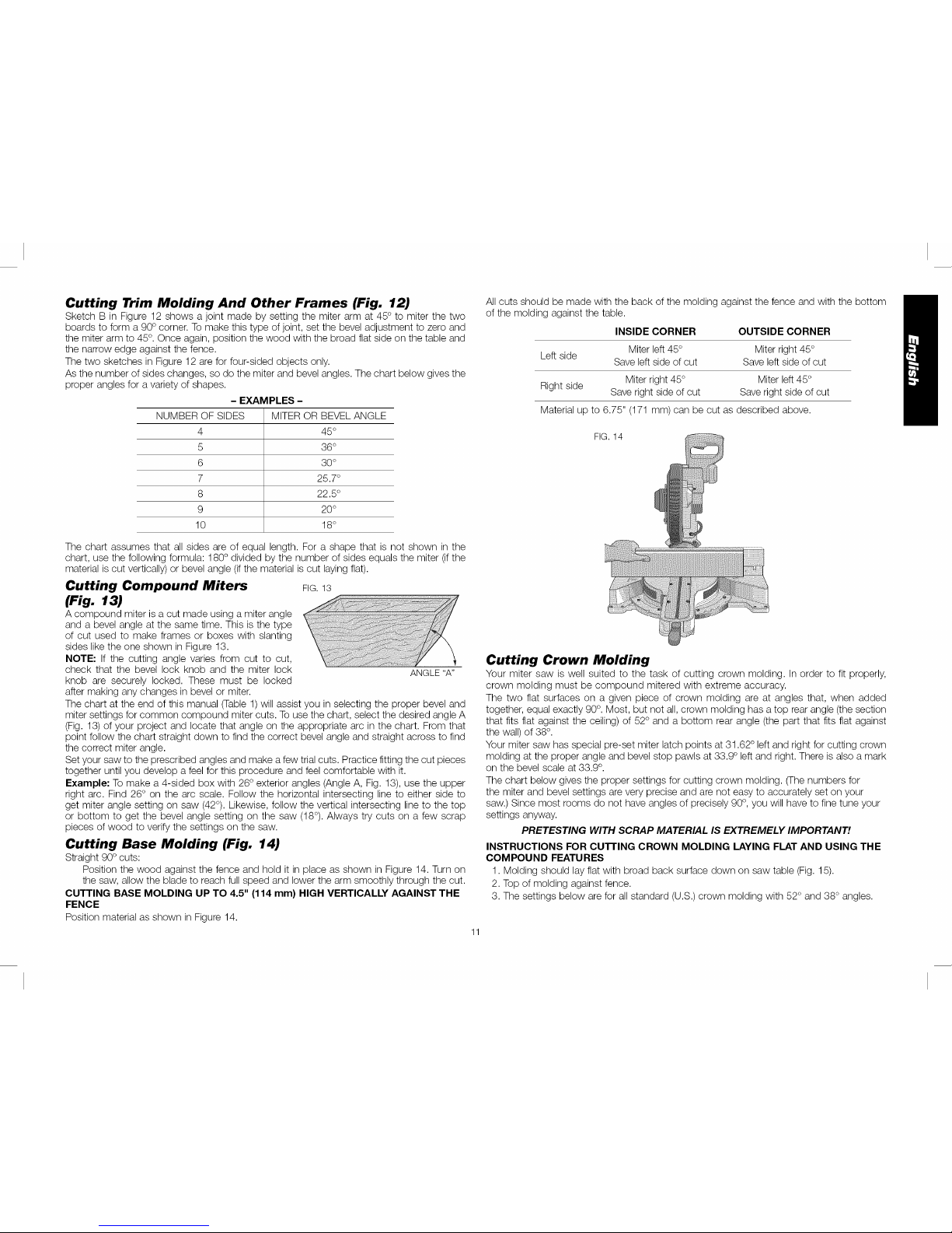
BEVEL SQUARE TO TABLE ADJUSTMENT
(FIG. 4, 6, 10)
Toalign the blade square to the table, lock the arm in the down position with the lock down
pin. Place a square against the blade, ensuring the square is not on top of a tooth. Loosen
the bevel lock knob and ensure the arm is firmly against the 0° bevel stop. Rotate the 0° bevel
adjustment screw with the 1/2" (13 mm) blade wrench as necessary so that the blade is at 0°
bevel to the table, as measured with the square.
FIG. 10
MITER LOCK
KNOB
BEVEL POINTERS (FIG. 6)
If the bevel pointers do not indicate zero, loosen each screw that holds each bevel pointer in
place and move them as necessary. Ensure the 0° bevel is correct and the bevel pointers are
set before adjusting any other bevel angle screws.
BEVEL STOP 45° RIGHT AND LEFT ADJUSTMENT (FIG. 4, 6}
Toadjust the right 45 ° bevel angle, loosen the bevel lock knob and pull the 0° bevel stop to
override the 0° bevel stop. When the saw is fully to the right, if the bevel pointer does not
indicate exactly 45°, turn the left 45 ° bevel adjustment screw with the 1/2" (13 mm) blade
wrench until the bevel pointer indicates 45°.
Toadjust the left 45 ° bevel stop, first loosen the bevel lock knob and tilt the head to the left.
If the bevel pointer does not indicate exactly 45 °, turn the right 45 ° bevel adjustment screw
until the bevel pointer reads 45 °.
FENCE ADJUSTMENT (FIG. 4)
In order that the saw can bevel to many bevel positions, one of the fences may have to be
adjusted to provide clearance. To adjust each fence, loosen the fence adjustment knob and
slide the fence outward. Make a dry run with the saw turned off and check for clearance.
Adjust the fence to be as close to the blade as practical to provide maximum workpiece
support, without interfering with arm up and down movement. Tighten the fence adjustment
knob securely. When the bevel operations are complete, don't forget to relocate the fence.
For certain cuts, it may be desirable to bring the fences closer to the blade. To use this feature,
back the fence adjustment knobs out two turns and move the fences closer to the blade past
the normal limit, then tighten the fence adjustment knobs to keep the fences in this location.
When using this feature, make a dry cut first to ensure the blade does not contact the fences.
NOTE: The tracks of the fences can become clogged with sawdust. If you notice that they are
becoming clogged, use a brush or some low pressure air to clear the guide grooves.
GUARD ACTUATION AND VISIBILITY (FIG. 4)
_CAUTION: Pinch hazard. To reduce the risk of injury,keep thumb underneath the operating
handle when pulling the handle down. The lower guard will move up as the operating handle
is pulled down, which could cause pinching.
The lower guard on your saw has been designed to automatically uncover the blade when the
arm is brought down and to cover the blade when the arm is raised.
The guard can be raised by hand when installing or removing saw blades or for inspection
of the saw. NEVER RAISE THE LOWER GUARD MANUALLY UNLESS THE BLADE IS
STOPPED.
NOTE: Certain special cuts of large material will require that you manually raise the guard.
Refer to Cutting Large Material under Special Cuts.
The front section of the guard is Iouvered for visibility while cutting. Although the louvers
dramatically reduce flying debris, they are openings in the guard and safety glasses should
be worn at all times.
KERF PLATE ADJUSTMENT (FIG. 4)
To adjust the kerf plate, loosen the screws holding the kerf plate in place. Adjust so that the
kerf plate does not interfere with the blade's movement.
RAIL GUIDE ADJUSTMENT (FIG. 4)
Periodically check the rails for any debris, play or clearance. The rails can be cleaned with a
dry clean cloth. The right rail can be adjusted with the set screw shown in Figure 4. To reduce
clearance, use a 4 mm hex wrench and rotate the set screw clockwise gradually while sliding
the saw head back and forth. Reduce play while maintaining minimum slide force.
Support for Long Pieces
_ WARNING: To reduce the risk of injury, turn unit off and disconnect it from power
source before installing and removing accessories, before adjusting or when making
repairs. An accidental start-up can cause injury.
ALWAYS SUPPORT LONG PIECES.
Never use another person as a substitute for a table extension, as additional support for a
workpiece that is longer or wider than the basic miter saw table or to help feed, support or
pull the workpiece.
For best results, use the DW7080 extension work support to extend the table width of your
saw, available from your dealer at extra cost. Support long workpieces using any convenient
means such as sawhorses or similar devices to keep the ends from dropping.
Cutting Picture Frames, Shadow Boxes And Other Four-
Sided Projects (Fig. 11, 12)
To best understand how to make the items listed here, we suggest that you try a few simple
projects using scrap wood until you develop a "feel" for your saw.
Your saw is the perfect tool for mitering corners like the one shown in Figure 11. Sketch A in
Figure 12 shows a joint made by using the bevel adjustment to bevel the edges of the two
boards at 45° each to produce a 90° corner. For this joint the miter arm was locked in the
zero position and the bevel adjustment was locked at 45°.The wood was positioned with the
broad flat side against the table and the narrow edge against the fence. The cut could also be
made by mitering right and left with the broad surface against the fence.
FIG. 11 FIG. 12
10
Page 12
Cutting Trim Molding And Other Frames (Fig. 12)
Sketch B in Figure 12 shows a joint made by setting the miter arm at 45° to miter the two
boards to form a 90° corner. To make this type of joint, set the bevel adjustment to zero and
the miter arm to 45 °. Once again, position the wood with the broad flat side on the table and
the narrow edge against the fence.
The two sketches in Figure 12 are for four-sided objects only.
As the number of sides changes, so do the miter and bevel angles. The chart below gives the
proper angles for a variety of shapes.
- EXAMPLES -
NUMBER OF SIDES MITER OR
4
5
6
7
8
9
10
BEVEL ANGLE
45°
36°
30°
25.7°
22.5°
20°
18°
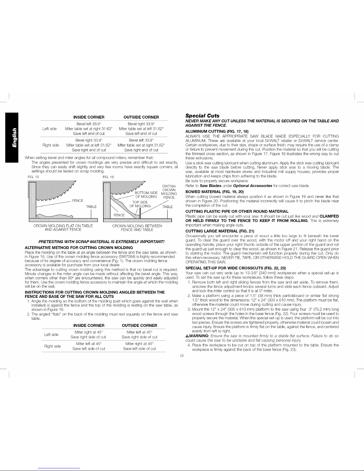
All cuts should be made with the back of the molding against the fence and with the bottom
of the molding against the table.
INSIDE CORNER OUTSIDE CORNER
Miter left 45 ° Miterright 45°
Left side
Save left side of cut Save left side of cut
Right side Miter right 45° Miter left 45°
Save right side of cut Save right side of cut
Material up to 6.75" (171 mm) can be cut as described above.
FIG. 14
The chart assumes that all sides are of equal length. For a shape that is not shown in the
chart, use the following formula: 180° divided by the number of sides equals the miter (if the
material is cut vertically) or bevel angle (if the material is cut laying flat).
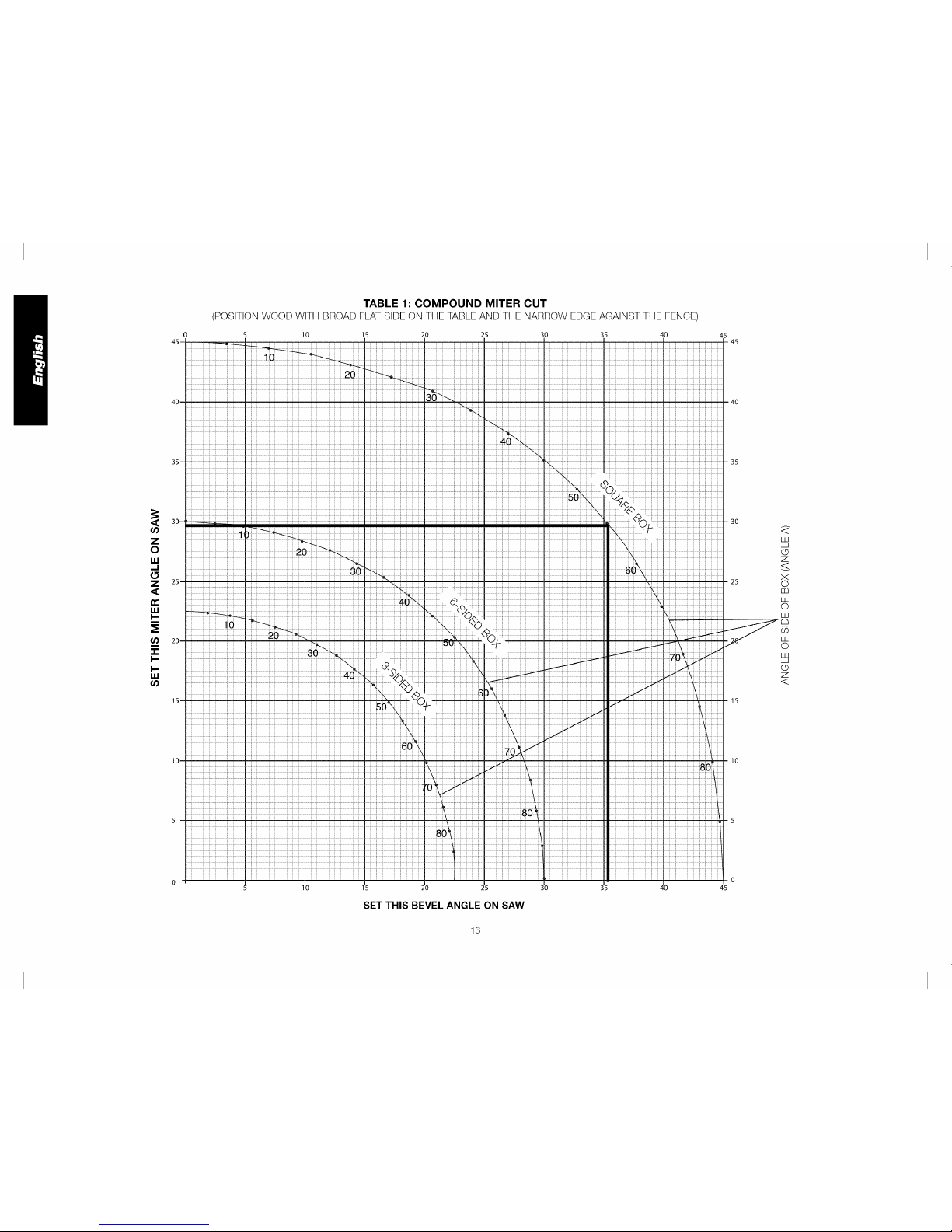
Cutting Compound Miters FIG.13
(Fig. 13)
A compound miter is a cut made using a miter angle
and a bevel angle at the same time. This is the type
of cut used to make frames or boxes with slanting
sides like the one shown in Figure 13.
NOTE: If the cutting angle varies from cut to cut,
check that the bevel lock knob and the miter lock
knob are securely locked. These must be locked
after making any changes in bevel or miter.
The chart at the end of this manual (Table 1) will assist you in selecting the proper bevel and
miter settings for common compound miter cuts. To use the chart, select the desired angle A
(Fig. 13) of your project and locate that angle on the appropriate arc in the chart. From that
point follow the chart straight down to find the correct bevel angle and straight across to find
the correct miter angle.
Set your saw to the prescribed angles and make a few trial cuts. Practice fitting the cut pieces
together until you develop a feel for this procedure and feel comfortable with it.
Example: To make a 4-sided box with 26° exterior angles (Angle A, Fig. 13), use the upper
right arc. Find 26° on the arc scale. Follow the horizontal intersecting line to either side to
get miter angle setting on saw (42°). Likewise, follow the vertical intersecting line to the top
or bottom to get the bevel angle setting on the saw (18°). Always try cuts on a few scrap
pieces of wood to verify the settings on the saw.
Cutting Base Molding (Fig. 14)
Straight 90° cuts:
Position the wood against the fence and hold it in place as shown in Figure 14. Turn on
the saw, allow the blade to reach full speed and lower the arm smoothly through the cut.
CUTTING BASE MOLDING UP TO 4.5" (114 ram) HIGH VERTICALLY AGAINST THE
FENCE
Position material as shown in Figure 14.
ANGLE "A"
Cutting Crown Molding
Your miter saw is well suited to the task of cutting crown molding. In order to fit properly,
crown molding must be compound mitered with extreme accuracy.
The two flat surfaces on a given piece of crown molding are at angles that, when added
together, equal exactly 90°. Most, but not all, crown molding has a top rear angle (the section
that fits flat against the ceiling) of 52° and a bottom rear angle (the part that fits flat against
the wall) of 38°.
Your miter saw has special pre-set miter latch points at 31.62 ° left and right for cutting crown
molding at the proper angle and bevel stop pawls at 33.9° left and right. There is also a mark
on the bevel scale at 33.9 °.
The chart below gives the proper settings for cutting crown molding. (The numbers for
the miter and bevel settings are very precise and are not easy to accurately set on your
saw.) Since most rooms do not have angles of precisely 90°, you will have to fine tune your
settings anyway.
PRETESTING WITH SCRAP MATERIAL IS EXTREMELY IMPORTANT!
INSTRUCTIONS FOR cu'rI'ING CROWN MOLDING LAYING FLAT AND USING THE
COMPOUND FEATURES
1. Molding should lay flat with broad back surface down on saw table (Fig. 15).
2. Top of molding against fence.
3. The settings below are for all standard (U.S.) crown molding with 52° and 38 ° angles.
11
Page 13
INSIDE CORNER OUTSIDE CORNER Special Cuts
Left side
Right side
Bevel left 33.9 ° Bevel right 33.9 °
Miter table set at right 31.62° Miter table set at left 31.62 °
Save left end of cut Save left end of cut
Bevel right 33.9 ° Bevel left 33.9 °
Miter table set at left 31.62 ° Miter table set at right 31.62 °
Save right end of cut Save right end of cut
When setting bevel and miter angles for all compound miters, remember that:
The angles presented for crown moldings are very precise and difficult to set exactly.
Since they can easily shift slightly and very few rooms have exactly square corners, all
settings should be tested on scrap molding.
FIG.15 FIG.16
FENCE
TABLE
iiiiiiiiiiiiiiiiiii
iiiiiiiiiiiiiiiiiii
iii!i!i:ii!ii;!iiii!i
CROWN MOLDING FLAT ON TABLE
AND AGAINST FENCE
iiiiiiiiii
iiiiiiiiii
iiiiiiiiii
!!!!!!!!!!
iiiiiiiiii
iiiiiiiiii
iiiiiiiiii
iiiiiiiiii
iiiiiiiiii
iiiiiiiiii
iiiiiiiiii
iiiiiiiiii
iiiiiiiiii
iiiiiiiiii
iiiiiiiiii
iiiiiiiiii
iiiiiiiiii
iiiiiiiiii
iiiiiiiiii
FENCE
DW7084
CROWN
BOTI-OM SIDE MOLDING
OF MOLDING FENCE
TABLE
CROWN MOLDING BETWEEN
FENCEAND TABLE
PRETESTING WITH SCRAP MATERIAL IS EXTREMELY IMPORTANT!
ALTERNATIVE METHOD FOR CUTTING CROWN MOLDING
Place the molding on the table at an angle between the fence and the saw table, as shown
in Figure 16. Use of the crown molding fence accessory (DW7084) is highly recommended
because of its degree of accuracy and convenience (Fig. 1). The crown molding fence
accessory is available for purchase from your local dealer.
The advantage to cutting crown molding using this method is that no bevel cut is required.
Minute changes in the miter angle can be made without affecting the bevel angle. This way,
when corners other than 90° are encountered, the saw can be quickly and easily adjusted
for them. Use the crown molding fence accessory to maintain the angle at which the molding
will be on the wall.
INSTRUCTIONS FOR CUTTING CROWN MOLDING ANGLED BETWEEN THE
FENCE AND BASE OF THE SAW FOR ALL CUTS
1. Angle the molding so the bottom of the molding (part which goes against the wall when
installed) is against the fence and the top of the molding is resting on the saw table, as
shown in Figure 16.
2. The angled "flats" on the back of the molding must rest squarely on the fence and saw
table.
INSIDE CORNER OUTSIDE CORNER
Left side Miter right at 45 ° Miter left at 45°
Save right side of cut Save right side of cut
Miter left at 45° Miter right at 45°
Right side
Save left side of cut Save left side of cut
12
NEVER MAKE ANY CUT UNLESS THE MATERIAL IS SECURED ON THE TABLE AND
AGAINST THE FENCE.
ALUMINUM CUTTING (FIG. 17, 18)
ALWAYS USE THE APPROPRIATE SAW BLADE MADE ESPECIALLY FOR CUTTING
ALUMINUM. These are available at your local DEWALT retailer or DRWALT service center.
Certain workpieces, due to their size, shape or surface finish, may require the use of a clamp
or fixture to prevent movement during the cut. Position the material so that you will be cutting
the thinnest cross section, as shown in Figure 17. Figure 18 illustrates the wrong way to cut
these extrusions.
Use a stick wax cutting lubricant when cutting aluminum. Apply the stick wax cutting lubricant
directly to the saw blade before cutting. Never apply stick wax to a moving blade. The
wax, available at most hardware stores and industrial mill supply houses, provides proper
lubrication and keeps chips from adhering to the blade.
Be sure to properly secure workpiece.
Refer to Saw Blades under Optional Accessories for correct saw blade.
BOWED MATERIAL (FIG. 19, 20)
When cutting bowed material always position it as shown in Figure 19 and never like that
shown in Figure 20. Positioning the material incorrectly will cause it to pinch the blade near
the completion of the cut.
cu'rI'ING PLASTIC PIPE OR OTHER ROUND MATERIAL
Plastic pipe can be easily cut with your saw. It should be cut just like wood and CLAMPED
OR HELD FIRMLY TO THE FENCE TO KEEP IT FROM ROLLING. This is extremely
important when making angle cuts.
cu'rI'ING LARGE MATERIAL (FIG. 21)
Occasionally you will encounter a piece of wood a little too large to fit beneath the lower
guard. To clear the guard over the wood, with the motor off and your right hand on the
operating handle, place your right thumb outside of the upper portion of the guard and roll
the guard up just enough to clear the wood, as shown in Figure 21. Release the guard prior
to starting the motor. The guard mechanism will function properly during the cut. Only do
this when necessary. NEVER TIE, TAPE, OR OTHERWISE HOLD THE GUARD OPEN WHEN
OPERATING THIS SAW.
SPECIAL SET-UP FOR WIDE CROSSCUTS (FIG. 22, 23)
Your saw can cut very wide (up to 13-3/8" [340 mm]) workpieces when a special set-up is
used. To set the saw up for these workpieces, follow these steps:
1. Remove both left and right sliding fences from the saw and set aside. To remove them,
unscrew the fence adjustment knobs several turns and slide each fence outward. Adjust
and lock the miter control so that it is at 0° miter.
2. Make a platform using a piece of 1.5" (38 mm) thick particleboard or similar flat strong
1.5" thick wood to the dimensions: 12" x 24" (305 x 610 mm). The platform must be flat,
otherwise the material could move during cutting and cause injury.
3. Mount the 12" x 24" (305 x 610 mm) platform to the saw using four 3" (76.2 mm) long
wood screws through the holes in the base fence (Fig. 22). Four screws must be used to
properly secure the material. When the special set-up is used, the platform will be cut into
two pieces. Ensure the screws are tightened properly, otherwise material could loosen and
cause injury. Ensure the platform is firmly flat on the table, against the fence, and centered
evenly from left to right.
i_WARNING: Ensure the saw is mounted firmly to a stable flat surface. Failure to do so
could cause the saw to be unstable and fall causing personal injury.
4. Place the workpiece to be cut on top of the platform mounted to the table. Ensure the
workpiece is firmly against the back of the base fence (Fig. 23).
Page 14
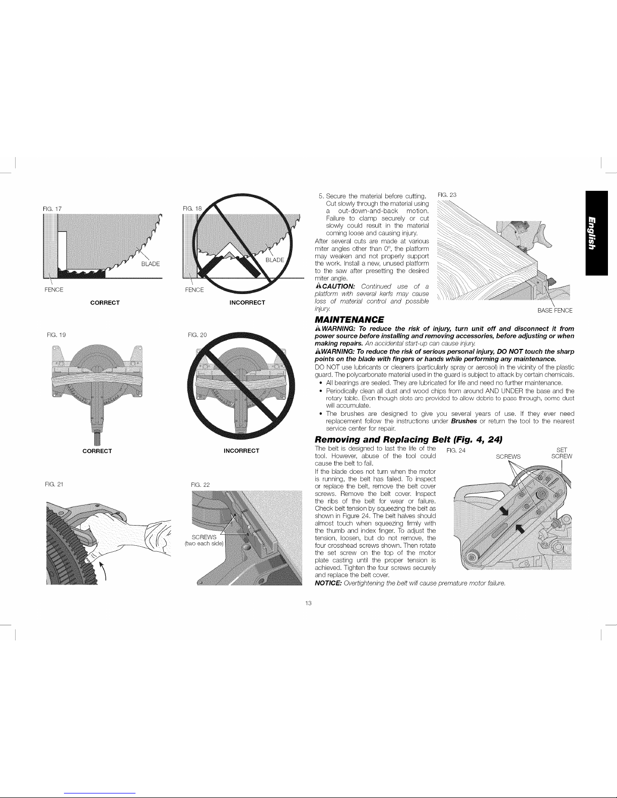
FIG.17
!
FENCE
FIG. 19
FIG. 21
CORRECT
CORRECT
BLADE
FIG. 18
FENCE
FIG. 20
FIG. 22
SCREWS
(two each side
INCORRECT
INCORRECT
5. Secure the material before cutting.
Cut slowly through the material using
a out-down-and-back motion.
Failure to clamp securely or cut
slowly could result in the material
coming loose and causing injury.
After several cuts are made at various
miter angles other than 0°, the platform
may weaken and not properly support
the work. Install a new, unused platform
to the saw after presetting the desired
miter angle.
_CAUTION: Continued use of a
platform with several kerfs may cause
loss of material control and possible
injury.
MAINTENANCE
FIG. 23
BASE FENCE
_ WARNING: To reduce the risk of injury, turn unit off and disconnect it from
power source before installing and removing accessories, before adjusting or when
making repairs. An accidental start-up can cause injury.
AWARNING: To reduce the risk of serious personal injury, DO NOT touch the sharp
points on the blade with fingers or hands while performing any maintenance.
DO NOT use lubricants or cleaners (particularly spray or aerosol) in the vicinity of the plastic
guard. The polycarbonate material used in the guard is subject to attack by certain chemicals.
• All bearings are sealed. They are lubricated for life and need no further maintenance.
• Periodically clean all dust and wood chips from around AND UNDER the base and the
rotary tablo. Evon though slots aro providod to allow dobris to pass through, somo dust
will accumulate.
• The brushes are designed to give you several years of use. If they ever need
replacement follow the instructions under Brushes or return the tool to the nearest
service center for repair.
Removing and Replacing Belt (Fig. 4, 24)
The belt is designed to last the life of the FIG.24
tool. However, abuse of the tool could
cause the belt to fail.
If the blade does not turn when the motor
is running, the belt has failed. To inspect
or replace the belt, remove the belt cover
screws. Remove the belt cover. Inspect
the ribs of the belt for wear or failure.
Check belt tension by squeezing the belt as
shown in Figure 24. The belt halves should
almost touch when squeezing firmly with
the thumb and index finger. To adjust the
tension, loosen, but do not remove, the
four crosshead screws shown. Then rotate
the set screw on the top of the motor
plate casting until the proper tension is
achieved. Tighten the four screws securely
and replace the belt cover.
NOTICE: Overtightening the belt will cause premature motor failure.
SET
SCREWS SCREW
13
Page 15
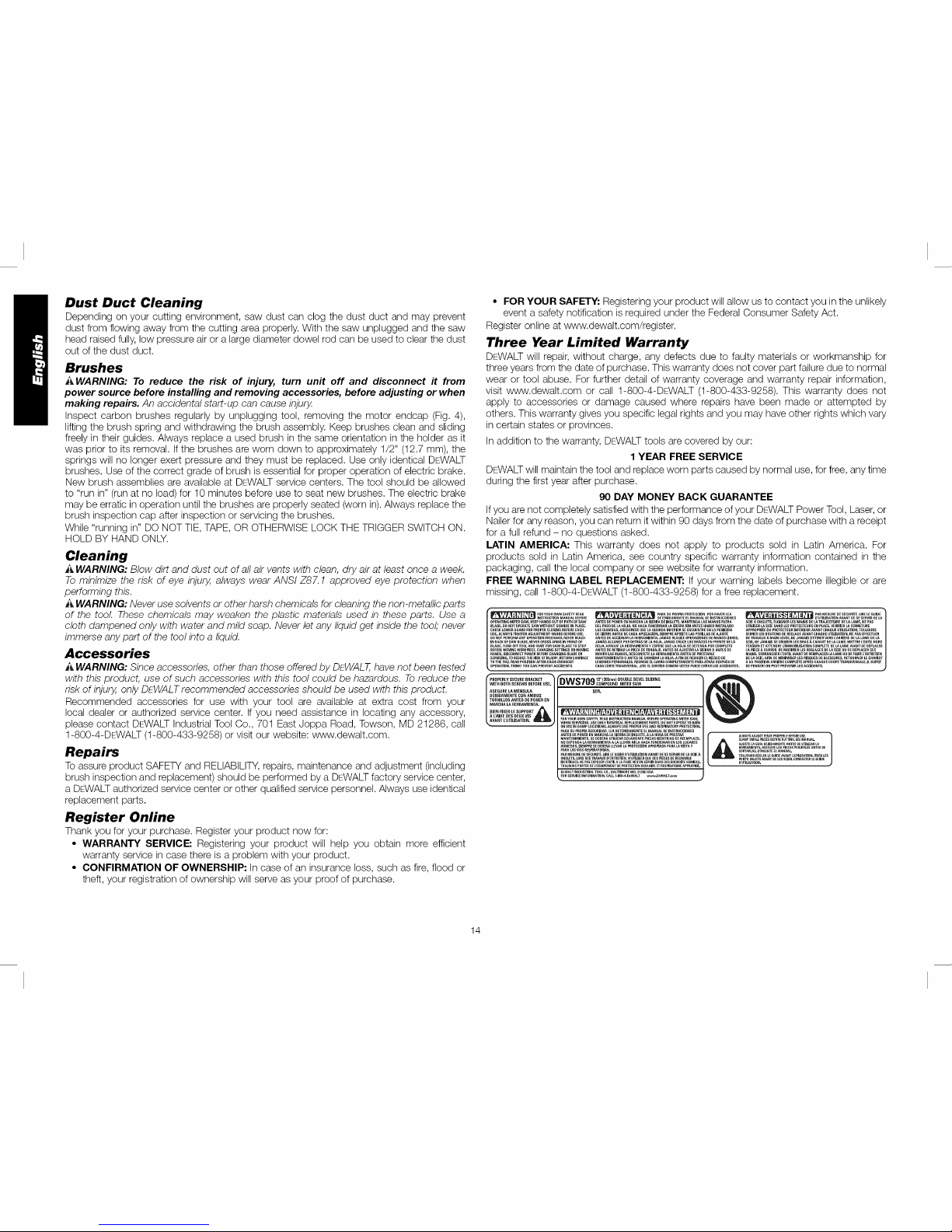
Dust Duct Cleaning
Depending on your cutting environment, saw dust can clog the dust duct and may prevent
dust from flowing away from the cutting area properly. With the saw unplugged and the saw
head raised fully, low pressure air or a large diameter dowel rod can be used to clear the dust
out of the dust duct.
Brushes
_ WARNING: To reduce the risk of injury, turn unit off and disconnect it from
power source before installing and removing accessories, before adjusting or when
making repairs. An accidental start-up can cause injury.
Inspect carbon brushes regularly by unplugging tool, removing the motor endcap (Fig. 4),
lifting the brush spring and withdrawing the brush assembly. Keep brushes clean and sliding
freely in their guides. Always replace a used brush in the same orientation in the holder as it
was prior to its removal. If the brushes are worn down to approximately 1/2" (12.7 mm), the
springs will no longer exert pressure and they must be replaced. Use only identical DEWALT
brushes. Use of the correct grade of brush is essential for proper operation of electric brake.
New brush assemblies are available at DEWALT service centers. The tool should be allowed
to "run in" (run at no load) for 10 minutes before use to seat new brushes. The electric brake
may be erratic in operation until the brushes are properly seated (worn in). Always replace the
brush inspection cap after inspection or servicing the brushes.
While "running in" DO NOT TIE, TAPE, OR OTHERWISE LOCK THE TRIGGER SWITCH ON.
HOLD BY HAND ONLY.
Cleaning
A WARNING: Blow dirt and dust out of all air vents with clean, dry air at least once a week.
To minimize the risk of eye injury, always wear ANSI Z87.1 approved eye protection when
performing this.
i_,WARNING: Never use solvents or other harsh chemicals for cleaning the non-metallic parts
of the tool. These chemicals may weaken the plastic materials used in these parts. Use a
cloth dampened only with water and mild soap. Never let any liquid get inside the tool,"never
immerse any part of the tool into a liquid.
Accessories
i_ WARNING: Since accessories, other than those offered by DEWALT,have not been tested
with this product, use of such accessories with this tool could be hazardous. To reduce the
risk of injury, only DEWALT recommended accessories should be used with this product.
Recommended accessories for use with your tool are available at extra cost from your
local dealer or authorized service center. If you need assistance in locating any accessory,
please contact DEWALT Industrial Tool Co., 701 East Joppa Road, Towson, MD 21286, call
1-800-4-DEWALT (1-800-433-9258) or visit our website: www.dewalt.com.
Repairs
Toassure product SAFETY and RELIABILITY,repairs, maintenance and adjustment (including
brush inspection and replacement) should be performed by a DEWALTfactory service center,
a DEWALT authorized service center or other qualified service personnel. Always use identical
replacement parts.
Register Online
Thank you for your purchase. Register your product now for:
• WARRANTY SERVICE: Registering your product will help you obtain more efficient
warranty service in case there is a problem with your product.
• CONFIRMATION OF OWNERSHIP: In case of an insurance loss, such as fire, flood or
theft, your registration of ownership will serve as your proof of purchase.
• FOR YOUR SAFETY: Registering your product will allow us to contact you in the unlikely
event a safety notification is required under the Federal Consumer Safety Act.
Register online at www.dewalt.com/register.
Three Year Limited Warranty
DEWALTwill repair, without charge, any defects due to faulty materials or workmanship for
three years from the date of purchase. This warranty does not cover part failure due to normal
wear or tool abuse. For further detail of warranty coverage and warranty repair information,
visit www.dewalt.com or call 1-800-4-DEWALT (1-800-433-9258). This warranty does not
apply to accessories or damage caused where repairs have been made or attempted by
others. This warranty gives you specific legal rights and you may have other rights which vary
in certain states or provinces.
In addition to the warranty, DEWALT tools are covered by our:
1 YEAR FREE SERVICE
DEWALTwill maintain the tool and replace worn parts caused by normal use, for free, any time
during the first year after purchase.
90 DAY MONEY BACK GUARANTEE
Ifyou are not completely satisfied with the performance of your DEWALT Power Tool, Laser, or
Nailer for any reason, you can return it within 90 days from the date of purchase with a receipt
for a full refund - no questions asked.
LATIN AMERICA: This warranty does not apply to products sold in Latin America. For
products sold in Latin America, see country specific warranty information contained in the
packaging, call the local company or see website for warranty information.
FREE WARNING LABEL REPLACEMENT: If your warning labels become illegible or are
missing, call 1-800-4-DEWALT (1-800-433-9258) for a free replacement.
mRYou_OWNSAFEty_EAO _ ,= _ . _',_RASUP_OP=Ar'_OTECC=ONF'O.F_,VO.LE,_ t , _ , r'r,RMES_RE[_ES_cu_rr_LIRELEGt_._E
OpERATpl_G MJTE_t SAW. KEEp HANDS 01iT 0F pATH OF SAW ANT_S I)E PONE_ £_ MA_tCHA tA SI£_BA OE=N6£ETE. MANTEN6A LAS MANOS FIJ£_tA SOlE A ON6LETS. EL016NER LES MAINS DE LA TRAJ£C_0I_E OE IA LAME. _£ PAS
BLAOE. O0 NOT OPERATE SAW WITHOUT GUARDS IN pLACe. DEL PASO [;E LA I_OJA. N_ HAGA FLtNCIONAS LA SIE_A Sbl AI_TE$ HAB£_t ]RSTALAOO UTILISE;_ LA $C1£ SANS LES p;_QTECT£URS £N pLACE. VERIFIE_t L_ F£RMETURE
CHECk( _OWl'_ GIJARI] F0R pff0p£_ CLOSING B£F0_E EACH LA$ GUARbA$. ASEG_IR_$E OlJE L_ GUA_0A INP_IOR SE E_CUE_;fRE EN LA pOSICP)N AppRoP_IEE Dr} PROTECTEtJ_ I_F_IEU_ AVAI_tT CHAQ_E UTI_$A'ilON. TOUJOUR$
USF. ALWAYS TIGHTEI_ AD JUSTMEI_T KI_O B$ SEFOSE US£, D£ _E_R_ AI_TES [_E CADA Apu_ACI(_N. SIEMPRE AP_JETE [AS pE_JLIA$ OE AJUSTE S£RR_8 LES BOUTONS 0£ REGLA_£ AVANT CHAQUE U_J_ISATION. I_E PAS £FF_CTUER
IN _AC_ (_F SAW BL_DE.N£VE_I CROSS ARi_S IN _0NT 0F JAMA$ ALCAaCE P0_ D£TRA$ OE _A H03A.._AMA$ CAUCE EOS B_J_ZOS EN FI_EI_TE OE LA $CIE. N£ 3AMAJS 8£ CBt_lSER LE$ BP,A$ _. _AVANT ,£ L¢ LAM£. METTRE _OUT_£ HOR$
BEAD£. TURN OFF TOOL AND WAIT FOR SAW BLAD_ TO STO_ HO3A. APAGUE LA HERRAMI_NTA y £SpE_£ QU£ LA HO,JA SE OETE_6A pOR COMPLETO TE_S!ON ET AITENDRE t:IMM OBILISATION _OMPLETE DE LA LAME AV/_I_ D£ 9£pLA_ER
BE_OR_MOVINGWOR_PIECE,CH/_NGINGSEttINGSORMOVING A_TES O__E_R_RL_ pIEZADETRASAJ_, Ak_TE$OEA,_U_R _ _IE_SA 0 _ES _E LA PIECEAOI_VRE_OEMODIfiER _S _EGtA6ES OELA SCI_Ol_OEI]EPLACER$E$
HANDS. DISCONNECT P[_W_R SEFO_tE _ffANGING 8LADE OR MOVER LAS MANOS. DESC6NECTE L_. HE_AMiEI'_TA ANTES O E P_ESTA_LE MAINS, D£S_ASCHER L'OUIIL AVANT DE _EMPL_CER LA lAME Og 0 EFAJ_E Z:ENT_E_i_
SER_CJN6,_ R_DUCETHE_SK OF_3URyr RETURN_AR_JAGE MANTENIr_IEI_TO0 ANT_$ OE;A_BI_R L_[tOJA, AFIN D_ _EDUCI_ELR!ESGOD_ ]1ELASClE,AFINOE MINIMISE_LES _ISOUESOEBLESSU_S _ETOUR_ERLECH_IOT
TO THE FU_L REAR posrRol_ AFTER EACH CSOSSCU7 LESiQNES pE_SONALE$, _EG_ES_ _L CAR_O COMPLETAMENTE PARA ATEAS DESpIJES _)E A SA POSITION A_IERE COMPLETE ApsEs CHAr_tlE COUPE TP_ANSVE_SALE, I_. $UFFIT
GPERATJON. THJN_ yG_ CA_ p_FVE_T A_CJDENTS. CAOA _ORTE TRAnSVErSAL. _USE [L SENTIDO COMON_ USTEO _EO[ EVffA_ LOS AC_IOENT_S. OE PENSER_ ON PE_T PREVENI_ LES ACCJOE_S.
14
Page 16

TROUBLE!
Saw will not start
Saw makes
unsatisfactory cuts
Blade does not come up
to speed
Machine vibrates
excessively
Does not make accurate
miter cuts
WHAT'S WRONG?
Troubleshooting Guide
BE SURE TO FOLLOW SAFETY RULES AND INSTRUCTIONS
WHAT TO DO
2. Fuse blown or circuit breaker tripped 2. Replace fuse or reset circuit breaker.
4. Brushes worn out
4. Have brushes replaced by authorized service center or replace them yourself. Refer to Brushes.
2. Blade mounted backwards
2. Turn blade around. Refer to Changing or Installing a New Saw Blade.
4. Incorrect blade for work being done 4. Change the blade type. Refer to Saw Blades under Optional Accessories.
2. Low house current
2. Contact your electric company.
2. Stand or bench on uneven floor
2. Reposition on flat level surface. Refer to Familiarization.
1. Miter scale not adjusted correctly 1. Check and adjust. Refer to Miter Scale Adjustment under Adjustments.
3. Blade is not perpendicular to table 3. Check and adjust fence. Refer to Bevel Square to Table Adjustment under Adjustments.
Material pinches blade 1. Cutting bowed material 1. Refer to Bowed Material under Special Cuts.
15
Page 17
0
45-
40=
35-
Z
0
W
--I
Z 2s-
t_
W
I/) 20-
-r
I--
I--
U,I
15-
10-
TABLE 1: COMPOUND MITER CUT
(POSITIONWOODWITH BROADFLATSIDEONTHETABLEANDTHE NARROWEDGEAGAINSTTHE FENCE)
15 20 25 30 35 40
SET THIS BEVEL ANGLE ON SAW
[Zi []] Z] Z] ]] Z] Z] iZi [Z!
4o
45
- 45
- 4O
- 35
- 3O
= 25
10
-0
45
<
Iii
©
Z
X
0
CO
LL
0
iii
LL
0
Iii
©
Z
<
16
Page 18

D_finitions : lignes directrices en
mati_re de s_curit_
Les definitions ci-dessous decrivent le niveau de danger pour chaque
mot-indicateur employe. Lirele mode d'emploi et porter une attention particuliere a.ces
symboles.
_,DANGER : indique une situation dangereuse imminente qui, si elle n'est pas evitee,
entraTnera la mort ou des blessures graves.
_AVERTISSEMENT : indique une situation potentie//ement dangereuse qui, si e//e
n'est pas evitee, pourraR entra_ner /a mort ou des blessures graves.
AATTENTION : indique une situation potentiel/ement dangereuse qui, si elle n'est pas
evitee, pourrait entra_ner des blessures I_g_res ou modifies.
AVIS : indique une pratique ne posant aucun risque de dommages corporels mais
qui par contre, si rien n'est fait pour I'eviter, pourrait poser des risques de dommages
materiels.
POUR TOUTE QUESTION OU REMARQUE AU SUJET DE CET OUTIL OU DE TOUT AUTRE
OUTIL DEWALT, COMPOSEZ LE NUMC:RO SANS FRAIS : 1-800-4-DEWALT (1-800-433-
9258).
_ VERTISSEMENT : afin de reduire /e risque de b/essures, /ire/e mode d'emp/oi de
I'outil.
Avertissements de s_curit_ g_n_raux
A AVERTISSEMENT ! Life tousles avertissements de s_curit_ et toutes les
directives. Le non-respect des avertissements et des directives pourrait se solder par
un choc dectrique, un incendie et/ou une blessure grave.
CONSERVER TOUS LES AVERTISSEMENTS ET TOUTES
LES DIRECTIVES POUR UN USAGE ULTERIEUR
Double isolation
Afin de proteger I'utilisateur contre les decharges electriques, les outils a.double isolation sont
completement recouverts de deux couches distinctes d'isolant electrique ou d'une simple
epaisseur renforcee de matiere isolante. Les outils comportant ce systeme d'isolation ne sont
pas con_us pour _tre mis a. la terre. L'outil est donc dote d'une prise a.deux broches qui
permet d'utiliser des rallonges sans avoir a. se soucier de maintenir une connexion a.la terre.
REMARQUE : le fait que cet outil soit muni d'une double isolation ne signifie pas que
rutilisateur peut cesser de respecter les consignes de securit6 qui s'imposent. L'isolation
secondaire offre une protection contre tout dommage corporel pouvant resulter d'une
defaillance electrique possible du systeme primaire d'isolation interne.
j_,ATTENTION : EN CAS DE REPARATION, UTILISER UNIQUEMENT DES PIECES DE
RECHANGE IDENTIQUES. Reparer ou remplacer les cordons d'alimentation endommages.
Fiches polaris_es
Certains appareils comportent des fiches polarisees (c'est-a.-dire qu'une lame est plus large
que I'autre) afin de reduire le risque de choc electrique. Lorsqu'elle est presente, cette fiche ne
se branche que d'une seule fa_on dans une prise de courant polarisee. Si la fiche ne s'insere
pas totalement dans la prise de courant, rinverser. Si elle ne s'insere toujours pas dans la
prise, demander a.un electricien competent d'installer une fiche polarisee. Ne pas remplacer
la fiche.
Consignes de s_curit_ pour tous les outils
_kAVERTISSEMENT : TOUJOURS utiliser une protection oculaire lots de I'utilisation
de la scie a onglets pour r_duire le risque de blessures aux yeux.
• MAINTENIR LE PROTEGE-LAME EN PLACE et en etat de fonctionnement.
• RETIRER LES CLES A MOLETTE ET LES CLES DE REGLAGE. S'habituer a verifier
si les cles a molette et les cles de reglage sont retirees de la broche avant de mettre I'outil
sous tension. Des outils, des dechets de decoupe et d'autres debris peuvent _tre projetes
grande vitesse, provoquant des blessures.
• GARDER LA ZONE DE TRAVAIL PROPRE. Les zones et etablis encombres sont
souvent des causes d'accidents.
• NE PAS UTILISER L'APPAREIL DANS UN ENVIRONNEMENT DANGEREUX.
L'utilisation d'outils dectriques dans des endroits humides ou mouilles ou sous la pluie peut
provoquer un choc dectrique ou une dectrocution. Tenir la zone de travail bien eclairee
pour eviter de trebucher ou de mettre bras, mains et doigts en danger.
• TENIR LES ENFANTS A L'E-CART. Tous les visiteurs doivent se trouver a une distance
sore de la zone de travail. Un atelier represente un environnement potentiellement
dangereux.
• S'ASSURER QUE L'ATELIER NE PRE'SENTE PAS DE DANGER POUR LES
ENFANTS : utiliser des cadenas, des interrupteurs principaux ou retirer les cles de
demarrage. Le demarrage non autorise d'un appareil par un enfant ou un visiteur pourrait
se solder par des blessures.
• NE PAS FORCER L'OUTIL. Le travail sera mieux accompli et sera moins dangereux au
rythme prevu pour I'appareil.
• UTILISER L'OUTIL APPROPRIE-. Ne pas forcer un outil ou un accessoire pour effectuer
un travail auquel il n'a pas ete conqu. L'utilisation d'un outil ou d'un accessoire inapproprie
pourrait se solder par des blessures corporelles.
• PORTER LES VE-TEMENTS APPROPRIE-S. Eviter v_tements amples, gants, cravates,
bagues, bracelets ou autres bijoux qui pourraient se prendre clans les pieces mobiles. IIest
recommande de porter des chaussures antiderapantes. Couvrir ou attacher les cheveux
longs
• TOUJOURS PORTER DES LUNETTES DE SE-CURITE-. Les lunettes ordinaires
ne constituent PAS des lunettes de securite. Utiliser egalement un masque facial ou
antipoussiere si I'operation de decoupe genere de la poussiere. TOUJOURS PORTER
UN EQUIPEMENT DE SECURITE HOMOLOGUE :
• protection oculaire conforme a la norme ANSI Z87.1 (CAN/CSA Z94.3) ;
• protection auditive conforme a la norme ANSI $12.6 ($3.19) ;
• protection des voies respiratoires conforme aux normes NIOSH/OSHA/MSHA.
• FIXER LA PIECE. Utiliser des brides de fixation ou un etau pour maintenir la piece sur la
table et contre leguide. Faire de m_me Iorsque le travail a effectuer exigera que la main de
I'operateur se trouve tres proche de la lame (a moins de 152 mm [6 po]). Une telle pratique
est plus securitaire, car I'operateur peut utiliser ses deux mains pour faire fonctionner I'outil.
• NE PAS TROP TENDRE LES BRAS. Conserver son equilibre en tout temps. Une perte
d'equilibre risque d'entra_ner une blessure corporelle.
• PRENDRE SOIN DES OUTILS. S'assurer que les outils sont aiguises et propres afin
d'optimiser securite et performance. Suivre les consignes de graissage et de changement
d'accessoires. Les machines et outils mal entretenus peuvent s'endommager davantage
et/ou provoquer des blessures.
• E'TEINDRE L'APPAREIL ET COUPER LE COURANT avant d'installer ou de retirer
des accessoires, avant de realiser ou de modifier un reglage et lots de reparations ou de
deplacements de I'appareil. Un demarrage accidentel peut provoquer des blessures. Ne
pas toucher aux lames metalliques de la fiche lots du branchement ou du debranchement
du cordon d'alimentation.
17
Page 19

REDUIRE LE RISQUE DE DEMARRAGE ACCIDENTEL. S'assurer que I'interrupteur
se trouve sur la position _ARRET _avant de brancher le cordon d'alimentation.
UTILISER UNE RALLONGE APPROPRIEE. S'assurer que la rallonge est en bon etat.
Lorsqu'une rallonge est utilisee, s'assurer d'utiliser un calibre suffisamment deve pour
assurer le transport du courant necessaire au fonctionnement de I'appareil. Une rallonge
de calibre inferieur causera une chute de tension de ligne et donc une perte de puissance
et une surchauffe. Le tableau suivant indique le calibre approprie a utiliser selon la Iongueur
de la rallonge et I'intensite nominale de la plaque signaletique. Encas de doute, utiliser le
calibre superieur suivant. Plus le numero de calibre est petit, plus le cordon est de calibre
deve.
Intensit_ nominale
Plus de
0
6
10
12
Calibre minimum pour rallonge
Volts Longueur totale du cordon
120 V 7,6 (25)
240 V 15,2 (50)
Pas plus de
6 5,5
10 5,5
12 4,9
16 4,3
(18)
(1S)
(16)
(14)
en mbtres (en pieds)
15,2 (50) 30,5 (100)
30,5 (100) 61,0 (200)
AWG
4,9 (16)
4,9 (16)
4,9 (16)
3,7 (12)
45,7(15o)
el ,4(300)
4,9 (16) 4,3 (14)
4,3 (14) 3,7 (12)
4,3 (14) 3,7 (12)
Non recommande
VERIFIER QUE LES PIECES NE SONT PAS ENDOMMAGEES. Avant toute
utilisation ulterieure de I'outil, un protege-lame (ou une autre piece) endommage doit _tre
soigneusement examine afin de determiner s'il fonctionnera correctement et remplira
sa fonction prevue - verifier I'alignement des pieces mobiles, la presence de grippage
des pieces mobiles, de rupture de pieces, la fixation et tout probleme pouvant nuire au
fonctionnement de I'outil. Un protege-lame (ou toute autre piece) endommage doit _tre
repare et remplace adequatement. Ne pas utiliser I'appareil si I'interrupteur ne fonctionne
pas.
• UTILISER LES ACCESSOIRES RECOMMANDES. N'utiliser que les accessoires
conseilles par le fabricant pour le modele de I'outil. Des accessoires qui conviennent
un outil pourraient _tre dangereux Iorsqu'ils sont utilises avec un autre outil. Une liste des
accessoires recommandes se trouve clans le mode d'emploL L'utilisation d'accessoires
incorrects peut entra_ner un risque de blessure corporelle.
• NE JAMAIS SE TENIR SUR L'OUTIL. Une blessure grave pourrait se produire en cas
de basculement de I'outil ou de demarrage accidentel de I'outil de decoupe.
• NE JAMAIS LAISSER L'OUTIL FONCTIONNER SANS SURVEILLANCE. ETEINDRE
L'APPAREIL. Ne pas laisser I'outil tant qu'il n'est pas completement arr_te. De graves
blessures pourraient survenir.
• NE PAS UTILISER D'OUTILS ELECTRIQUES A PROXIMITE DE LIQUIDES
INFLAMMABLES OU DANS UNE ATMOSPHERE GAZEUSE OU EXPLOSIVE. Les
moteurs de ces outils peuvent provoquer des etincelles et enflammer des vapeurs.
• ETRE VIGILANT, SURVEILLER LE TRAVAIL EFFECTUE ET FAIRE PREUVE DE
JUGEMENT. NE PAS UTILISER L'APPAREIL EN CAS DE FATIGUE OU SOUS
L'INFLUENCE DE DROGUES, D'ALCOOL OU DE MEDICAMENTS. En effet, un
moment d'inattention en utilisant des outils dectriques peut se solder par des blessures.
R_gles de s_curit_ suppl_mentaires pour les scies
onglets
AAVERTISSEMENT: ne pas laisser une bonne connaissance de I'outil (acquise par
I'utilisation frequente de la scie) prendre preseance sur les regles de securite. Toujours se
souvenir qu'une fraction de seconde d'imprudence est suffisante pour infliger de graves
blessures.
18
• NE PAS FAIRE FONCTIONNER CET APPAREIL avant qu'il ne soit entierement
assemble et installe conformement aux directives. Un appareil mal assemble peut
provoquer des blessures graves.
• DEMANDER CONSEIL a un superviseur, a un instructeur ou a toute autre personne
qualifiee si I'on ne ma_trisepas parfaitement I'utilisation de cet appareil. La connaissance
est synonyme de securite.
• STABILITE. S'assurer que la scie a onglets est posee sur une surface portante fixe et ne
risque pas de glisser ou de se deplacer durant son utilisation.
• SUIVRE TOUS LES CODES DE CABLAGE et les branchements dectriques
recommandes afin d'eviter les chocs dectriques ou I'dectrocution. IIfaut proteger la ligne
d'alimentation dectrique avec un fusible a temporisation ou un disjoncteur d'au moins
15 amperes.
• S'ASSURER que la lame toume dans le bon sens. Les dents de la lame doivent pointer
dans le sens de rotation, comme il est indique sur la scie.
• SERRER TOUTES LES POIGNEES DE FIXATION, les boutons et les leviers avant
I'utilisation de la scie. Si les brides sont I_ches, des pieces ou la piece a travail/erpourraient
_tre projetees a grande vitesse.
• S'ASSURER QUE la lame au complet et les attaches de lame sont propres, que les c6tes
encastres des attaches de lame sont appuyes sur la lame et que la vis de I'arbre est bien
settee. Un mecanisme de serrage de lame I_che ou mal installe risque d'endommager la
scie et de provoquer des blessures corporelles.
• UTILISER TOUJOURS UNE LAME TRANCHANTE. Verifier que la lame fonctionne
bien clans I'axe et qu'elle ne vibre pas. Une lame emoussee ou une lame qui vibre peut
endommager I'appareil et/ou provoquer des blessures graves.
• NE PAS UTILISER UNE TENSION AUTRE QUE CELLE DESIGNEE pour la scie.
Une tension autre risquerait d'entra_ner une surchauffe, des dommages a la scie et des
blessures corporelles.
• NE PAS PLACER QUOI QUE CE SOIT CONTRE LE VENTILATEUR pour retenir
I'arbre moteur. Une telle pratique peut endommager I'outil et entra_ner des blessures
corporelles.
• NE PAS FORCER L'ACTION DE COUPE. Le calage partiel ou complet du moteur peut
causer des dommages a I'appareil ou a la lame et/ou des blessures graves.
• LAISSER LE MOTEUR ATTEINDRE SON PLEIN REGIME avant de commencer
la coupe. Commencer a couper trop t6t peut endommager I'appareil ou la lame et/ou
provoquer des blessures graves.
• NE JAMAIS COUPER DE METAUX FERREUX (metaux contenant du fer ou de I'acier)
ni de la maqonnerie. En coupant I'un ou I'autre de ces materiaux, les pointes carburees
peuvent se detacher de la lame, et ce, a grande vitesse. Cela peut provoquer des
blessures graves.
• NE PAS UTILISER DE MEULES ABRASIVES. La chaleur excessive et les particules
abrasives qu'elles produisent risquent d'endommager la scie et de causer des blessures
corporelles.
• AUCUNE PARTIE DU CORPS NE DOlT SE TROUVER DANS LA TRAJECTOIRE
DE LA LAME DE LA SCIE. Un tel positionnement risque d'entra_ner des blessures
corporelles.
• NE JAMAISAPPLIQUER DE LUBRIFIANTSUR UNE LAME EN FONCTIONNEMENT.
L'application de lubrifiant pourrait amener I'operateur a deplacer ses mains jusque sur la
lame et ainsi se blesser gravement.
• IL NE FAUT PAS placer une main a proximite de la lame Iorsque la scie est branchee
au bloc d'alimentation. Le fonctionnement inopine de la lame risquerait d'entra_ner des
blessures graves.
NE PAS EFFECTUER D'OPERATION A MAIN LEVEE (Iorsque la piece n'est soutenue
ni par une table ni par un guide). Maintenir la piece a travailler fermement contre le guide
Page 20

et la table. Les operations a main levee sur une scie a onglet pourraient entra_nerle rejet
violent de la piece posant ainsi des risques de dommages corporels graves.
• NE PAS PASSER LES MAINS AUTOUR DE LA LAME DE SCIE OU DERRIERE
CELLE-CI. Une lame peut provoquer des blessures graves.
• IL NE FAUT PAS PASSER LES MAINS SOUS LA SCIE saul si elle est hors tension et
debranchee. Tout contact avec la lame de scie pourrait entra_nerdes blessures corporel/es.
• FIXER L'APPAREIL SUR UNE SURFACE DE SUPPORT STABLE. Les vibrations sont
susceptibles de faire glisser, sautiller ou basculer I'appareil, ce qui peut provoquer des
blessures graves.
• UTILISER UNIQUEMENT LES LAMES A TRON_ONNER recommandees pour les
scies a onglets. Pour des resultats optimums, ne pas utiliser de lames a pointes de carbure
avec un angle d'attaque superieur a 7 degres. Ne pas utiliser des lames a dents tres
espacees. Celles-ci peuvent devier et faire contact avec le protege-lame et endommager
ainsi I'appareil et/ou provoquer des blessures graves.
• UTILISER SEULEMENT DES LAMES DE DIMENSION ET DE TYPE APPROPRIES
prevues pour cet outil, et ce, pour eviter d'endommager I'apparei/ et/ou d'entra_ner des
blessures graves.
• INSPECTER LA LAME POUR REPERER DES FISSURES ou d'autres dommages
avant I'utilisation. Une lame fissuree ou endommagee peut se detacher et des fragments
peuvent _tre projetes a grande vitesse, ce qui peut provoquer des blessures graves.
Remplacer les lames fissurees ou endommagees immediatement.
• NETTOYER LA LAME ET LES ATTACHES DE LAME avant I'utilisation. Le nettoyage
de la lame et des attaches de lame permet de detecter tout dommage a la lame ou aux
attaches de lame. Une lame ou une attache de lame fissuree ou endommagee peut se
detacher et des fragments peuvent _tre projetes a grande vitesse, ce qui peut provoquer
des blessures graves.
• IL NE FAUT PAS utiliser de graisse ni de produits nettoyants (en particulier de
pulverisateur ou d'aerosol) a proximite du protege-lame en plastique. Certains produits
chimiques peuvent attaquer le materiau de polycarbonate dont il est constitue.
• TOUJOURS UTILISER LA PLAQUE DE TRAIT DE SCIE ET LA REMPLACER
LORSQU'ELLE EST ENDOMMAGEE. L'accumulation de petits copeaux sous la scie
pourrait nuire a la lame ou rendre la piece instable lots de la decoupe.
• UTILISER SEULEMENT LES ATTACHES DE LAME PREVUES POUR CET OUTIL
afin de prevenir tout dommage et/ou des blessures graves.
• DE-GAGER LES E-VENTS DU MOTEUR de toute sciure ou de tout copeau. Des events
de moteur obstrues peuvent provoquer la surchauffe de I'appareil, ce qui l'endommagerait
et provoquerait peut-_tre un court-circuit qui pourrait engendrer des blessures graves.
• TENIR LES BRAS, LES MAINS ET LES DOIGTS E'LOIGNE'S DE LA LAME afin
d'eviter des coupures graves. Fixer solidement toutes les pieces qui exigeraient que la
main soit a moins de 152 mm (6 po) de la lame de scie.
• NE JAMAIS VERROUILLER L'INTERRUPTEUR EN POSITION DE _ MARCHE _ .
Une tel/e pratique peut entra_nerdes blessures corporelles graves.
• E-TEINDRE L'APPAREIL et laisser la lame s'immobiliser completement avant de relever
le bras, de nettoyer la zone de la lame, d'enlever les debris de la trajectoire de la lame et
avant I'entretien ou le reglage de I'outil. Une lame mobile peut provoquer des blessures
graves.
• SOUTENIR CORRECTEMENT LES PIECES LONGUES OU LARGES La perte de
contr61e de la piece peut provoquer des blessures.
• NE JAMAIS CROISER LES BRAS DEVANT LA LAME au moment d'utiliser I'outil.
Toujours effectuer un fonctionnement a sec (non alimente) avant de realiser une coupe
de finition. Ainsi, la trajectoire de la lame peut _tre verifiee, ce qui permet d'eviter toute
blessure corporelle grave.
• DES INFORMATIONS SUPPLE-MENTAIRES (c.-a-d., une video sur la securite),
indiquant comment utiliser des outils dectriques correctement et en toute securite, sont
19
disponibles aupres du Power ToolInstitute, 1300 Sumner Avenue, Cleveland, OH 44115-
2851 E.-U. (www.powertoolinstitute.com). Des renseignements sont egalement offerts
par le National Safety Council, 1121 Spring Lake Drive, Itasca, IL 60143-3201 E.-U. Se
reporter a la norme ANSI 01.1 de I'American National Standards Institute concemant
les exigences en matiere de securite pour les appareils de travail du bois ainsi qu'a la
reglementation OSHA 1910.213 du departement du travail des E.-U. (Department of
Labor).
._AVERTISSEMENT : ne connectez pas I'appareil a une source d'alimentation dectrique
tant que vous n'avez pas completement lu et compris les instructions.
_AVERTISSEMENT : toujours porter une protection auditive appropri_e
conform_ment a la norme ANSI $12.6 ($3.19) lots de I'utilisation du produit. Dans
certaines conditions et selon la duree d'utilisation, le bruit emis par ce produit pourrait
contribuer a une perte auditive.
_AVERTISSEMENT : NE JAMAIS EFFECTUER DE COUPE SI LE MATERIAU N'EST PAS
MAINTENU EN PLACE SUR LA TABLE E-i-CONTRE LE GUIDE.
J_AVERTISSEMENT : les scies, meules, ponceuses, perceuses ou autres outils de
construction peuvent produire des poussieres contenant des produits chimiques reconnus
par I'Etat califomien pour causer cancers, malformations congenitales ou _tre nocifs au
systeme reproducteur. Parmi ces produits chimiques, on retrouve :
• Le plomb dans les peintures a base de plomb ;
• La silice cristallisee dans les briques et le ciment, ou autres produits de maqonnerie ;
et
• L'arsenic et le chrome dans le bois ayant subi un traitement chimique.
Les risques relies a I'exposition aces poussieres varient selon la frequence a laquelle vous
travaillezavec ce type de materiaux. Afin de reduire votre exposition a ces produits chimiques :
travaillez dans un endroit bien ventile et portez un equipement de securite approuve comme
un masque anti-poussieres conqu specialement pour filtrer les particules microscopiques.
• Evitez le contact prolong_ avec les poussi_res produites par les activit_s de
ponqage, sciage, meulage, perqage et autres activit_s de construction. Portez
des v_tements de protection et lavez les parties du corps expos_es avec une
solution d'eau et de savon. Le fait de laisser la poussi_re p_n_trer par la bouche
et les yeux ou de la laisser reposer sur la peau, peut promouvoir I'absorption de
produits chimiques nocifs.
_AVERTISSEMENT : I'utilisation de cet outil peut produire ou propulser des poussieres qui
pourraient causer des problemes respiratoires graves et permanents ou d'autres problemes
medicaux. Portez toujours un appareil respiratoire approuve par la NIOSH/OSHA pour vous
proteger de lapoussiere. Dirigez les particules a I'ecart de votre visage et de votre corps.
Pour plus de commodite et de securite, les etiquettes de securite suivantes sont apposees
sur votre scie a onglet.
SUR LE BOiTIER DU MOTEUR :
_AVERTISSEMENT: POUR VOTRE SECURITE, VEUILLEZ LIRE LE MODE
D'EMPLOI AVANT D'UTILISER LA SCIE A ONGLETS.
EN CAS DE REPARATION, UTILISER UNIQUEMENT DES PIECES DE RECHANGE
IDENTIQUES.
PROTEGER DE LA PLUIE ET NE PAS UTILISER DANS DES ENDROITS HUMIDES.
PORTER SYSTEMATIQUEMENT UN SYSTEME DE PROTECTION OCULAIRE ET
DES VOLES RESPIRATOIRES ADEQUATS.
SUR LES GUIDES MOBILES :
AJUSTEZ TOUJOURS
CORRECTEMENT LE GUIDE
AVANT UTILISATION. FIXEZ LES
PETITES PIECES AVANT DE LES
DECOUPER. VOIR LE MANUEL.
ALWAYSADJUST FENCE PROPERLY BEFGREUSE,
CLAMPSMALL PIECESBEFORECUTTING, SEE MANUAL,
AJUSTE LA GUiA OEDIDAMENTE ANTES DE UTJiJZAR LA
HERRAMiENTA. ASEGURE LAG PJEZAS PEUUENAS ANTES DE
CORTARLAS.CONSULTE EL MANUAL.
TOUJOURG REGLER LEGUIDE AVANT idUTJLJSATION. FIXER LEG
PETITS OBJETS AVANT DELEG SCIER. CONSULTER LE GUIDE
D'NTILISATIO N.
Page 21

SUR LE PARE-MAIN :
DANGER - RESTEZ A L'E'CART DE LA LAME.
KE£P AWAY
SUR LE PARE-MAIN SUPERIEUR : ........
MANTENERSALEJADO
OELA HOJA
FIXEZ BIEN LE SUPPORT DE FIXATION AVEC LES DEUX VIS ,E.............
AVANT D'UTILISER LE PRODUIT.
SUR LA TABLE : (A 2 ENDROITS)
I_A VERTISSEMENT : POUR VOTRE SE'CURITE', PRIE'REDE LIRE LE
MODE D'EMPL OIA VANTD'UTILISER LA SCI EA ONGLETS. GARDER
LES MAINS HORS DE LA TRAJECTOIRE DE LA LAME DE LA SCIE.
NE PAS UTILISER LA SCIE SANS QUE LES PARE-MAINS NE SOIENT
EN PLACE. VE'RIFIER,A VANTCHAQUE USAGE, QUE LE PARE-MAIN INFE'RIEUR SE
FERME BIEN. TOUJOURS BIEN SERRER LES RE'GLAGES AVANT UTILISATION.
EFFECTUER TOUTE OPE'RATION EN TENANT L'OUTIL DES DEUX MAINS. NE
JAMAIS PASSER LES MAINS A L'ARRIE'RE DE LA LAME DE LA SCIE. NE JAMAIS
PASSER LES BRAS DEVANT LA LAME. E'TEINDRE L'OUTIL ET ATTENDRE
L'ARRE'T DE LA LAME DE LA SCIE AVANT DE DE'PLACER LA PIE'CE, DE
MODIFIER LES RE'GLAGES OU DE DE'PLACER LES MAINS. DE'BRANCHER LA
SCIE AVANT DE REMPLACER UNE LAME OU PROCE'DER A UNE RE'PARATION.
AFIN DE RE'DUIRE LES.RISQUES DE BLESSURES, LAISSER LA SCIE REVENIR
EN POSITION COMPLETEMENT RELEVEE APRES CHAQUE UTILISATION. IL
SUFFIT DE RE'FLE'CHIR! VOUS POUVEZ EMPE'CHER LES ACCIDENTS.
SUR LE SOCLE : (A 2 ENDROITS)
Connexion dlectrique
Assurez-vous que votre alimentation est compatible avec I'inscription de la plaque signaletique.
120 volts, C.A. signifie que votre scie fonctionne en courant alternatif. L'interrupteur est
susceptible de panne en cas d'utilisation de courant continu. Une diminution de tension de
10 pour cent ou plus cause une perte de puissance et une surchauffe. Tous les outils DEWALT
sont testes en usine. Si cet outil ne fonctionne pas, verifiez ralimentation.
Accessoires
_u4VERTISSEMENT : puisque les accessoires autres que ceux offerts par DEWALT n'ont
pas ete testes avec ce produit, I'utilisation de ceux-ci avec I'outil pourrait s'averer dangereuse,
Pour reduire le risque de blessures, utiliser exclusivement les accessoires DEWALT
recommandes avec le present produit,
Les accessoires recommandes pour cet outil sont vendus separement au centre de service
de votre region. Pour obtenir de raide concernant I'achat d'un accessoire, communiquer
avec DEWALT Industrial Tool Co., 701 East Joppa Road, Towson, MD 21286 aux Etats-Unis;
composer le 1 (800) 4-DEWALT (1-800-433-9258) ou visiter notre site Web : www.dewalt.
com.
Accessoires facultatifs (fig. 1)
Les accessoires suivants, con_us pour votre scie, peuvent vous _tre utiles. Dans certains cas,
d'autres supports d'ouvrage, butees reglables, fixations, etc. peuvent _tre plus appropries.
Faites attention Iors du choix et de rutilisation d'accessoires.
Support d'ouvrage t_lescopique : DW7080
II est utilise pour soutenir de Iongues pieces qui depassent Le support d'ouvrage est
assemble par I'utilisateur. La base de la scie a et6 con_ue pour recevoir deux supports
d'ouvrage, un de chaque cOte.
FIG. 1
PLAQUE
D'EXTRI2MITI2
ECROUS DE
VERROUILLAGE
i
DW7051
SUPPORT
POIGNEES
DW7082
DW7053
Butte r_glable : DW7051
Necessite rutilisation d'un support d'ouvrage (DW7080) (se reporter a, la figure 1). Elle
sert a,effectuer des decoupes repetitives de m6me Iongueur (comprise entre 0 et 107 cm
[42 po]).
Bride de fixation : DW7082 (modUle semblable inclus)
Sert a,fixer fermement la piece sur la table a,scier pour une decoupe de precision.
Sac a poussi_re : DW7053
Equipe d'une fermeture a,glissiere pour un vidage facile, le sac a,poussiere capture la plus
grande partie de la sciure produite.
Guide de rnoulures couronn_es : DW7084
Sert pour la decoupe de precision de moulures couronnees.
LAMES DE SCIE :TOUJOURS UTILISER DES LAMES DE SCIE DE 305 mm (12 po) AVEC
UN ALe:SAGE CENTRAL DE SOIT 25,4 mm (1 po) SOIT 15,88 mm (5/8 po). LE RI2GIME
DOlT IeTRE AU MOINS DE 4 800 TR/MIN. Ne jamais utiliser de lames de diametre inferieur.
Le protege-lame ne serait pas adequat. Utiliser uniquement des lames a,trongonner ! Ne
pas utiliser de lames congues pour un sciage rapide, des lames combinees ou des lames
a,crochets d'un angle superieur a,7°.
2O
Page 22

DESCRIPTION DES LAMES
APPLICATION DIAM#TRE DENTS
Lames de scie de construction (fin trait de scie avec c6te anticollant)
Polyvalente 305 mm (12 pc) 40
Trongonnage fin 305 mm (12 pc) 60
Lames de scie pour travail du bois (foumissent des coupes propres et regulieres)
Trongonnage fin 305 mm (12 pc) 80
Metaux non ferreux 305 mm (12 pc) 96
REMARQUE : pour couper des metaux non ferreux, utiliser seulement des lames a,
dents TCG (broyeur de particules triple) congues a,cet effet.
D_semballage de votre scie
Verifiez le contenu du carton de votre scie b,onglet pour verifier que toutes les pieces vous ont
et6 livrees. En plus de ce mode d'emploi, le carton devrait contenir :
1 Scie a,onglet DWS709
1 Lame de scie DEWALT de 305 mm (12 pc) de diametre
Dans le sac :
1 Cle de lame
1 Sac a,poussiere DW7053
1 Bride de fixation de materiel
Caract_ristiques techniques
CAPACIT# DE D#COUPE
Onglet gauche a,50 °, Onglet droit a,60°
Biseau droit et gauche a,49°
HAUTEU R LARGEU R
Onglet 0°/Biseau 0° 114 mm (4-1/2 pc) 243 mm (9-9/16 pc)
Onglet 45°/Biseau 0° 114 mm (4-1/2 pc) 171 mm (6-1/16 pc)
Onglet 50°/Biseau 0° 114 mm (4-1/2 pc) 155 mm (6-1/16 pc)
Onglet 60°/Biseau 0° 114 mm (4-1/2 pc) 110 mm (4-5/16 pc)
Biseau 45° - Gauche/Onglet 0° 62 mm (2-7/16 pc) 243 mm (9-9/16 pc)
Biseau 45° - Droit/Onglet 0° 43 mm (1-11/16 pc) 243 mm (9-9/16 pc)
Moulure couronnee a,plat
(angle a, ressort 38) 72 mm (2-13/16 pc) 206 mm (8-1/16 pc)
Moulure couronnee a,plat
(angle a, ressort 45) 33 mm (1-1/4 pc) 198 mm (7-3/4 pc)
REMARQUE : La scie est capable de decouper de la maniere suivante Iorsqu'une procedure
de configuration speciale est suivie. Consulter D_coupes sp_ciales.
HAUTEUR LARGEUR
Onglet 0°/Biseau 0° 75 mm (2-15/16 pc) 340 mm (13-3/8 pc)
Onglet 45°/Biseau 0° 53 mm (2-1/16 pc) 250 mm (9-13/16 pc)
Onglet 50°/Biseau 0° 53 mm (2-1/16 pc) 232 mm (9-1/8 pc)
Onglet 45° - Gauche/Onglet 0° 23 mm (7/8 pc) 354 mm (9-9/16 pc)
HAUTEU R LARG EUR
Moulure couronnee a,plat
(angle a, ressort 38) 23 mm (7/8 pc) 288 mm (11-5/16 pc)
Moulure couronnee a,plat
(angle a, ressort 45) 23 mm (7/8 pc) 276 mm (10-7/8 pc)
ENTRAJNEMENT
Moteur 120 V
Puissance d'entree 1600 watts Moteur 15 amp.
3 800 r/min Engrenages helico'l'dauxtailles
Courroie a,rainures multiples Roulements a,rouleaux
Frein electrique automatique Lame au carbure
Familiarisation FIG.2
Votre scie a, onglet est livree entierement
assemblee dans le carton. Ouvrez le carton et
sortez la scie en la prenant par les indentations
de prise de sa base, comme illustre en figure 2.
Placez la scie sur une surface lisse et plane telle
qu'un etabli ou une table solide.
Examinez les figure 4 vous familiariser avec
la scie et ses differentes pieces. La section
concernant les reglages se referera a,ces termes
et vous devez savoir quelles sont les differentes
pieces et o0 elles se trouvent.
i_4TTENTION : risques de pincement, Pour
reduire tout risque de dommages corporels,
maintenir le pouce sous la poignee de
fonctionnement pour la rabaisser, Le pare-
main inferieur s'devera alors que la poignee
de fonctionnement sera abaissee, pouvant ainsi occasionner de pincements, La poignee de
fonctionnement est placee pres du pare-main pour des coupes particulieres,
Appuyez legerement sur la poignee de fonctionnement et tirez sur la goupille de blocage.
Relb,chez doucement la pression verticale et maintenez la poignee de fonctionnement tout en
lui permettant de s'elever a, son maximum. Utilisez la goupille de blocage pour transporter la
scie d'un lieu a, I'autre. Utilisez systematiquement les indentations de prise pour transporter la
scie, comme illustre en figure 4.
Montage sur _tabli
Les 4 pieds sont munis de trous pour faciliter le montage sur etabli, tel qu'illustre a,la figure 4
(deux trous de taille differente sont prevus afin d'accueillir des vis de differentes tailles. Utilisez
I'un des trous, il n'est pas necessaire d'utiliser les deux.) Assemblez toujours fermement votre
scie sur une surface stable pour eviter tout mouvement. Pour ameliorer la portabilite de I'outil,
il peut _tre monte sur une piece de contreplaque de 12,7 mm (1/2 pc) ou plus d'epaisseur,
qui peut a, son tour _tre fixee a,votre support d'ouvrage ou deplacee vers un autre site de
travail et fixee a,nouveau.
REMARQUE : si vous avez decide de monter votre scie sur une piece de contreplaque,
assurez-vous que les vis de montage ne depassent pas de la partie inferieure du bois. Le
contreplaque doit reposer a, plat sur le support d'ouvrage. Lors de la fixation de la scie a,toute
surface de travail, ne la fixez que sur les brides de fixation o0 se situent les trous des vis de
montage. L'agripper sur tout autre point interferera avec le bon fonctionnement de la scie.
21
Page 23

FIG.3
C
A
B
G
_LATTENTION : pour eviter tout grippage et manque de
precision, assurez-vous que la surface de montage n'est
pas tordue et ne presente pas d'autre defaut. Si la scie
bascule sur la surface, placez une piece de materiau de
faible epaisseur sous I'un des pieds de la scie, jusqu'a ce
que cette demiere soit fermement assise sur la surface de
montage.
DIRECTIVES DE SECURITE
IMPORTANTES
Changement ou pose d'une nouvelle
lame de scie (fig. 3)
_ A VERTISSEMENT :pour r_duire le risque de blessures,
_teindre I'appareil et le d_brancher avant d'installer
ou de retirer tout accessoire et avant d'effectuer des
reglages ou des r_parations. Un demarrage accidentel peut
provoquer des blessures.
i_u4TTENTION :
• N'enfoncezjamais le bouton de verrouillage de la
broche Iorsque la lame est sous tension ou qu'elle
continue de toumer apres I'arr_t de la scie.
• Ne coupez pas de metal ferreux (contenant du fer
ou de I'acier), un dement de maqonnerie ou du
fibrociment avec cette scie a onglet.
D_pose de la lame (fig. 3)
1. Debranchez la scie.
2. Soulevez le bras jusqu'a la position superieure, puis
levez le pare-main (A)aussi haut que possible.
3. Desserrez la vis du support du pare-main (B) sans
I'enlever de maniere a.ce que le support puisse _tre leve
suffisamment haut pour acceder a.la vis de la lame (E).
Le pare-main inferieur demeurera leve en raison de la
position de la vis du support de pare-main.
4. Enfoncez le bouton de verrouillage de la broche (C) tout
en tournant la lame de scie manuellement de maniere a.
engager le dispositif de verrouillage.
5. Maintenez le bouton enfonce et utilisez I'autre main et la
cle fournie (D) pour desserrer la vis de la lame. (Tournez
dans le sens horaire, filets inverses.)
6. Enlever la vis (E), I'attache de lame exterieure (F),la lame
(G) et I'adaptateur de lame (H), si utilise. Uattache de
lame de fixation interieure (I) peuvent _tre laisses sur la
broche.
REMARQUE : I'adaptateur de lame de 25,4 mm (1 po) (H)
n'est pas utilise pour les lames dotees d'un trou de lame de
15,88 mm (5/8 po).
Pose d'une lame (fig. 3)
1. Debranchez la scie.
2. Avec le bras releve, le dispositif de protection inferieur
ouvert sur son support, placer la lame sur la broche, sur
I'adaptateur de lame (si une lame a. trou de 25,4 mm
[1 po] est utilisee), et contre I'attache de lame de fixation
interieure, les dents se trouvant au bas de la lame et
pointant vers I'arriere de la scie.
3. Installez I'attache de lame exterieure sur la broche.
4. Posez la vis de la lame et, tout en engageant le bouton
de verrouillage de la broche, serrez fermement la vis
avec la cle fournie (tournez dans le sens antihoraire, filets
inverses).
REMARQUE : Iorsqu'une lame avec un alesage central
de 15,88 mm (5/8 po) est utilisee, I'adaptateur de lame
n'est pas utile et doit _tre range soigneusement pour future
utilisation. L'adaptateur de lame n'est pas disponible avec
tousles modeles.
5. Remettez le support de pare-main a.sa position d'origine,
puis serrez fermement la vis du support de pare-main
afin de maintenir en place le support.
_AVERTISSEMENT:
• Le support du pare-main doll _tre remis dans sa
position originale et sa vis soigneusement serr_e
avant I'activation de la scie.
• Si vous n_gligez du faire, le pare-main risque
d'entrer en contact avec la lame de scie
tournante et ainsi causer des dommages a la
scie et des des blessures corporelles s_rieuses
Transport de la scie
i_ A VERTISSEMENT :pour r_duire le risque de blessures,
_teindre I'appareil et le d_brancher avant d'installer
ou de retirer tout accessoire et avant d'effectuer des
r_glages ou des r_parations. Un demarrage accidentel peut
provoquer des blessures.
i_4VERTISSEMENT : pour r_duire tout risque
de d.ommages corporels graves, verrouiller
SYSTEMATIQUEMENT /a mo/ette de verroui//age de raft,
/abouton de verroui//age d'ong/et, /a manette de verroui//age
de biseau, /a goupi//e de b/ocage, et /ebouton de reg/age de
guide, avant de transporter la scie.
Pour faciliter le deplacement de la scie a.onglet d'un lieua. un
autre, utilisez les indentations de prise sur sa base, comme
illustre en figure 4.
CARACTERISTIQUES ET OPTIONS
_ A VERTISSEMENT :pour r_duire le risque de blessures,
_teindre I'appareil et le d_brancher avant d'installer
ou de retirer tout accessoire et avant d'effectuer des
r_glages ou des r_parations. Un demarrage accidentel peut
provoquer des blessures.
COMMANDES D'ONGLET (FIG. 5}
Le bouton de verrouillage d'onglet et le bouton de Ioquet
d'onglet permettent d'ajuster I'onglet de votre scie a. 60° a.
droite et 50° a.gauche. Pour ajuster I'onglet, tournez bouton
de verrouillage d'onglet vers la gauche puis appuyez sur le
bouton de Ioquet d'onglet et ajustez I'angle d'onglet desire
sur I'echelle d'onglet. Resserrez soigneusement lebouton de
verrouillage d'onglet.
22
Page 24

POIGNEEDE DI2TENTE
FONCTIONNEMENT
FIG.4
POIGNEEDE
BLOCAGEDERAIL
RI2GLAGEDELA
VISDECALAGE
DURAIL CAPUCHONDU
MOTEUR
BO/TIERDU
MOTEUR
PARE-MAIN
INFI2RIEUR
COUVERCLEDE
COURROIE
ECHELLE
DEBISEAU
GOUPILLEDE
VERROUILLAGE
POIGNEEDE
RI2GLAGEDEGUIDE
(unedechaquec6te)
PLAQUEDE
TRAITDESCIE
CLI2DE
LAME
VISDE
RI2GLAGEDE
BISEAU#,45°
(unedechaque
c6te)
CONDUITE#,
POUSSIERE
BUTI2EDE
BISEAU#,0°
MOLETTEDE
VERROUILLAGE
DEBISEAU
DISPOSITIFSDE
NEUTRALISATION
DELABUTI2EDU
BISEAU45°(une
dechaquec6te)
POIGNEEDE
RI2GLAGE
DEGUIDE
(unede
chaque
c6te)
GUIDE
INDENTATIONTABLE
DEPRISE
Echelle
D'ONGLET
ORIFICES DE MONTAGE
SUR ETABLI
BOUTON DE
LOQUET
D'ONGLET
BOUTON DE
VERROUILLAGE
D'ONGLET
FIG. 5
VIS
(4 endroits)
ECHELLE
D'ONGLET
POINTEUR
D'ONGLET
VIS DE POINTEUR
D'ONGLET
BOUTON DE
VERROUILLAGE
D'ONGLET
BOUTON
DE LOQUET
D'ONGLET
23
Page 25

D#TENTE (FIG. 4)
La detente met en marche et arr_te la scie. Un trou est prevu dans I'interrupteur pour y inserer
un cadenas et verrouiller la scie.
MOLE'rI'E DE VERROUILLAGE DE BISEAU (FIG. 4)
Le verrouillage de biseau vous permet de regler le biseau de la scie a,49 ° a,gauche ou a,droite.
Pour regler le parametre de biseau, tournez le bouton vers la gauche. La t_te de scie ajuste
facilement le biseau vers la gauche ou la droite une fois que la molette d'annulation de biseau
a,0° est tiree. Pour la resserrer, tournez la molette de verrouillage de biseau vers la droite.
ANNULATION DU BISEAU ._ 0° (FIG. 4, 6)
L'annulation de butee de biseau permet de regler le biseau de la scie vers la droite, au-dela,
du repere de 0°.
Une fois activee, la scie s'arr_tera automatiquement sur la butee a,0° Iorsqu'elle sera amenee
depuis la gauche. Pour passer au-delb, de 0° a, droite, tirez sur la molette de verrouillage de
biseau. Une fois la molette relb,chee, le mecanisme d'annulation sera reactive. La molette de
verrouillage de biseau peut _tre deverrouillee en la tournant a, 180°.
_, 0°, le mecanisme d'annulation est verrouille. Pour activer le mecanisme d'annulation,
inclinez la scie legerement vers la gauche.
DISPOSITIFS DE NEUTRALISATION DE LA BUT#E DU BISEAU 45 o (FIG. 4)
Les dispositifs de neutralisation de la butee du biseau sont maintenus fixes par leur vis de
fixation pour eviter tout deplacement imprevu. Utiliser la meche de la cle de la lame pour
desserrer la vis de fixation. Cela permet aux glissieres d'etre tirees vers I'exterieur et de faire
pivoter la t_te de la scie au-dela, du repere de 45 o. S'assurer de resserrer la vis de fixation
apres avoir termine.
FIG. 6
VIS DE POINTEUR DE BISEAU
(une de chaque c0L_)
ECHELLE DE BISEAU
POINTEUR DE BISEAU
(une de chaque c6te)
VIS DE REGLAGE DE
BISEAU _, 0°
POIGN#E DE BLOCAGE DE RAIL (FIG. 4)
La poignee de blocage de rail vous permet de verrouiller fermement la t_te de scle pour
I'emp_cher de glisser sur les rails. C'est necessaire pour effectuer certaines coupes ou pour
transporter la scie.
GOUPILLE DE BLOCAGE (FIG. 4}
_AVERTISSEMENT : la goupille de blocage ne doit _tre utilisee que pour transporter ou
entreposer la scie, Ne JAMAIS utiliser la goupille de blocage pendant la decoupe,
Pour verrouiller la t_te de scie en position basse, poussez la t_te de scie vers le bas, poussez
sur la goupille de blocage puis relb,chez la t_te de scie. Cela maintiendra solidement la t_te de
scie en position basse pour deplacer la scie d'un lieu a, I'autre. Pour la liberer,appuyez sur la
t_te de scie et retirez la goupille.
FREIN #LECTRIQUE AUTOMATIQUE
Votre scie est equipee d'un frein de lame electrique automatique qui arr_te la lame de la scie
dans les 5 secondes qui suivent le rel_,chement de la detente. Cela n'est pas reglable.
Un delai peut parfois se produire entre le relb,chement de la detente et I'engagement du frein.
En de rares occasions, le frein peut ne pas s'engager du tout et la lame ralentira jusqu'a,
s'arr_ter completement.
Si un delai ou un _,saut ,, se produit, allumez et eteignez la scie 4 ou 5 fois. Si le probleme
persiste, faites reparer I'outil par un centre de service agree DEWALT.
Assurez-vous toujours que la lame s'est arr_tee avant de la retirer du trait de scie. Le frein
n'est pas un remplacement pour les pare-mains. Pour assurer votre securite, concentrez-vous
entierement sur la scie.
FONCTIONNEMENT
_AVERTISSEMENT : pour r_duire le risque de blessures, _teindre I'appareil et le
d_brancher avant d'installer ou de retirer tout accessoire et avant d'effectuer des
reglages ou des r_parations. Un demarrage accidentel peut provoquer des blessures,
JL4VERTISSEMENT : toujours porter une protection oculaire. Tousles utilisateurs et
spectateurs doivent porter une protection oculaire conforme a la norme ANSI Z87,1 (CAN/
CSA Z94,3),
=b_4VERTISSEMENT : pour s'assurer que le chemin de lame est libre de toute obstruction,
faire un passage de coupe a vide, hors tension, avant de commencer de couper la piece
travailler,
Branchez la scie sur une alimentation domestique standard en 60 Hz. Referez-vous a, la
plaque sJgnal®tJquepour la tension. Assurez-vous que le cordon n'interterera pas avec votre
travail.
Ddtente (fig. 4)
Pour mettre I'outil en marche, appuyez sur la detente. Pour arr_ter I'outil, rel_,chezla detente.
Laissez la lame tourner a,plein regime avant de commencer la decoupe. Rel_,chez la detente
et laissez le frein arr_ter la lame avant de soulever la t_te de scie. La detente ne peut _tre
verrouillee en marche, mais un trou est prevu dans I'interrupteur pour y inserer un cadenas et
verrouiller la scie a,I'arr_t.
Ddcoupe _ I'aide de votre scie
Si la fonction de glissement n'est pas utilisee, s'assurer que la t_te de la scie est reculee aussi
loin que possible et que la poignee de blocage de rail est serree. Cela permettra d'eviter que
la scie glisse le long de ses rails quand la piece de travail est engagee.
REMARQUE : m_me si cette scie peut decouper le bois et de nombreux matieriaux
non ferreux, nous limiterons les explications detaillees a, la decoupe du bois. Les m_mes
directives s'appliquent aux autres materiaux. NE COUPEZ PAS A L'AIDE DE CETTE
SCIE DE MATERIAU FERREUX (FER ET ACIER) OU D'#L#MENT DE MAQONNERIE.
N'utilisez pas de lame abrasive.
REMARQUE : se reporter au paragraphe Activation du pare-main et visibilit_ sous la
section R_glages pour obtenir des informations importantes sur le pare-main inferieur
avant la decoupe.
COUPES TRANSVERSALES
Une coupe transversale est une coupe de bois effectuee au travers du fil a, n'importe quel
angle. Une coupe transversale droite s'effectue avec le bras d'onglet en position zero degre.
Reglez et verrouillez le bras d'onglet a,zero, maintenez fermement le bois en place sur la table
24
Page 26

et contre le guide. Apres avoir serre la poignee de blocage de rail, mettez la scie en marche
en appuyant sur la detente vers le bas comme illustre a,la figure 4.
Lorsque la scie atteint son plein regime (en environ 1 seconde), baissez doucement et
lentement le bras pour decouper le bois. Laissez la lame s'arr_ter completement avant de
relever le bras.
Lors de la decoupe de toute piece plus grande que 51 x 203 mm (2 x 8 po [ou 51 x 152 mm
(2 x 6) avec un onglet a,45°]), utilisez un mouvement exterieur-bas-retour apres avoir desserre
la poignee de blocage de rail. Tirez la scie vers vous, abaissez la t_te de scie vers la piece et
repoussez lentement la scie pour terminer la coupe. Ne laissez pas la scie entrer en contact
avec le sommet de la piece Iorsque vous tirez dessus. La scie pourrait se deplacer rapidement
vers vous et pourrait entratner une blessure corporelle ou endommager votre piece.
La decoupe de plusieurs pieces n'est pas recommandee mais elle peut _tre effectuee en
toute securit6 en s'assurant que chaque piece est maintenue fermement en place contre la
table et le guide.
REMARQUE • afin d'augmenter la capacite de coupe transversale avec des coups de scie
reduits, la lame du DWS709 s'etend plus profondement dans la table. II s'ensuit que la force
de levage exercee sur la piece durant la coupe peut _tre plus importante.
_AVERTISSEMENT : utilisez systematiquement une bride de fixation pour maintenir le
contr61e de la piece a travailler et reduire les risques de dommages materiels et corporels, si
vos mains doivent se trouver dans 152 mm (6 po) de la lame pendant la decoupe,
REMARQUE • la poignee de blocage de rail illustree a, la figure 4 doit _tre desserree pour
permettre a, la scie de glisser le long de ses rails.
Les coupes transversales d'onglet sont effectuees avec le bras d'onglet regle sur un angle
autre que zero. Cet angle est souvent a,45 ° pour faire des coins, mais il peut _tre ajuste
differemment entre zero et 50° a,gauche ou 60° a,droite. Effectuez la coupe comme decrit
ci-dessus.
Si vous effectuez une coupe a,onglet sur une
piSce d'une largeur sup6rieure _,2 x 6, mais de
Iongueur inferieure, placez systematiquement
le c6te le plus long le long du guide (fig. 7).
Pour couper une piece en suivant une ligne
au crayon, essayer de faire correspondre le
plus possible rangle. Couper d'abord la piece
un peu plus Iongue puis mesurer de la ligne
au crayon au bord coupe pour determiner la
direction de reglage de rangle d'onglet puis
couper de nouveau. II faut un peu de pratique
mais cette technique demeure toutefois tres
utilisee.
FIG. 7
COUPES EN BISEAU
Une coupe en biseau est une coupe
transversale effectuee alors que la lame de
scie forme un angle avec le bois. Pour regler
le biseau, desserrez le verrouillage de biseau
(fig.4), et deplacez la scie sur la droite ou sur la
gauche comme desire (deplacez le guide pour
laisser un espace suffisant le cas echeant). Une
fois I'angle de biseau desire ajuste, resserrez fermement leverrouillage de biseau. Reportez-
vous a, la section Caract_ristiques et options pour des instructions detaillees quant au
dispositif a,biseau.
Les angles de biseau peuvent _tre definis entre 49 ° a, droite et 49° a,gauche et peuvent _tre
coupes avec I'arbre a,onglet positionne entre 50 ° a,gauche et 60° a, droite. Dans le cas de
certains angles extremes, il est possible de devoir retirer le guide de gauche ou de droite.
Pour retirer le guide droit ou gauche, devissez la poignee de reglage de guide de plusieurs
tours puis enlevez-le.
REMARQUE • se reporter au paragraphe Ajustement du guide sous la section R_glages
pour des informations importantes quant au reglage des guides pour certaines coupes en
biseau.
OUALIT¢ DE COUPE
La qualite de toute coupe depend de plusieurs variables, Des parametres tels que lemateriau
coupe, le type de lame, la durete de la lame et lavitesse de coupe contribuent tous a,la qualite
de coupe.
Lorsqu'une coupe plus fluide est desiree pour les moulures ou tout autre travail de precision,
une lame affutee (60 dents au carbure ou plus) et une vitesse de coupe plus lente et reguliere
produira les resultats desires.
S'assurer que le materiau ne bougera ou ne glissera pas pendant la decoupe; rarrimer
soigneusement en place. Attendre systematiquement rarr_t complet de la lame avant de
soulever le bras de scie.
Si de petites fibres de bois sont toujours projetees a,I'arriere de la piece, placez un morceau
de ruban adhesif de carrossier sur le bois a, I'endroit oO la coupe sera effectuee. Sciez a,
travers le ruban adhesif et retirez-le soigneusement Iorsque vous avez termine.
Pour differentes applications de coupe, consultez la liste de lames de scie recommandees
pour votre outil et selectionnez celle qui s'adapte le mieux a,vos besoins. Consulter Lames
de scie sous Accessoires facultatifs.
POSITION DU CORPS ET DES MAINS (FIG. 8A-8D)
Un positionnement adequat de votre corps et de vos mains Iors de I'utilisation de la scie
a,onglet rendra la coupe plus facile, plus precise et plus sore. Ne placez jamais vos mains
a,proximite de la zone de coupe. Ne les placez pas a, moins de 152 mm (6 po) de la lame
Maintenez fermement la piece en place contre la table et le guide pendant I'operation de
coupe. Gardez vos mains en position jusqu'au rel_,chement de la d_tente et L_I'arr_t complet
de la lame. EFFECTUEZ TOUJOURS DES ESSAIS _,BLANC (SANS ALIMENTATION) AVANT
DE RC:ALISER VOS COUPES AFIN DE VI_RIFIER LA TRAJECTOIRE DE LA LAME. NE
CROISEZ PAS LES MAINS, TEL QU'ILLUSTR¢: _, LA FIGURE 8C.
Gardez vos pieds ancres au sol afin de maintenir votre equilibre. Lorsque vous deplacez le
bras d'onglet vers la gauche ou la droite, suivez-le et tenez-vous legerement sur le c6te de
la lame de la scie. Observez au travers des persiennes du pare-main Iorsque vous suivez un
trait tire au crayon.
FIXATION DE LA PII_CE
J_AVERTISSEMENT : pour r_duire le risque de blessures, _teindre I'appareil et le
d_brancher avant d'installer ou de retirer tout accessoire et avant d'effectuer des
r_glages ou des r_parations. Un demarrage accidentel peut provoquer des b/essures,
J_AVERTISSEMENT : une piece de travail qui est abloquee, equilibree et fixee avant d'etre
coupee peut devenir desequilibree apres la coupe, Une charge desequilibree risque de faire
basculer la scie ou toute chose a laquelle la scie est fixee, comme une table ou un etabli,
Au moment de couper une piece qui risque d'etre desequilibree, s'assurer qu'elle est bien
soutenue et que la scie est bien boulonnee a une surface stable, Sinon, il y aurait risque de
blessures corporelles,
J_4VERTISSEMENT : le pied de la bride doit _tre encastre au-dessus de la base de la scie
chaque lois que la bride est utilisee, Toujours setter la piece a la base de la scie et non a une
autre partie de la zone de travail, S'assurer que le pied de la bride n'est pas serre au bord de
la base de la scie,
_ ATTENTION: utilisez systematiquement une bride de fixation pour maintenir le contr61e de
la piece a travailler et reduire les risques de dommages materiels et corporels, si vos mains
doivent se trouver dans 152 mm (6 po) de la lame pendant la decoupe,
25
Page 27

FIG.8A
FIG.8C
COUPEADI2QUATE
COUPEINADI2QUATE
Si vous ne pouvez pas manuellement maintenir la piece sur
la table et contre le guide (b,cause d'une forme irreguliere ou
d'une autre raison) ou que votre main se trouverait a,moins
de 152 mm (6 pc) de la lame, vous devez utiliser un pinceur
de travail ou une autre fixation.
Utilisez la bride de fixation de materiel fournie avec votre scie.
Pour acheter une bride de fixation, veuillez contacter votre
detaillant local ou un centre de reparation DEWALT,
D'autres accessoires tels que pinces a,ressort, serres a,barre
ou serre-joint en C peuvent 6tre adaptees a, certaines tailles
et formes de materiaux. Pr6tez attention Iors de la selection
et de la pose de ces fixations. Prenez le temps d'effectuer
un essai a, blanc avant d'entamer la coupe. Les guides
de gauche et de droite coulissent d'un c6te a,I'autre pour
faciliter I'operation de pingage.
INSTALLATION DE LA BRIDE
1. L'inserer dans le trou situe derriere le guide. La bride doit
6tre face a,I'arriere de la scie a,onglets. La rainure Iogee
dans la tige de la bride doit 6tre bien inseree dans la
base. S'assurer que cette rainure est bien inseree dans
la base de la scie a,onglets. Si la rainure est visible, cela
signifie que la bride est mal fixee.
FIG. 8B
COUPE ADI2QUATE
FIG. 8D
COUPE INADI2QUATE
2. Tourner la bride de 180 ° vers I'avant de la scie a,onglets.
3. Desserrer la poignee pour monter ou descendre la
bride, puis utiliser le bouton de reglage fin pour serrer
fermement la piece.
REMARQUE: placer la bride du cOte oppose a,la base pour
le biseautage. TOUJOURS EFFECTUER DES MARCHES
A SEC (SANS ALIMENTATION) AVANT DE REALISER
VOS COUPES AFIN DE VERIFIER LA TRAJECTOIRE DE
LA LAME. S'ASSURER QUE LA BRIDE N'OBSTRUE PAS
LE MOUVEMENT DE LA SCIE OU DES DISPOSITIFS DE
PROTECTION.
R_.GLAGES
_ A VERTISSEMENT :pour r_duire le risque de blessures,
_teindre I'appareil et le d_brancher avant d'installer
ou de retirer tout accessoire et avant d'effectuer des
r_glages ou des r_parations. Un demarrage accidentel peut
provoquer des blessures,
Votre scie a,onglet a et6 parfaitement et precisement reglee
en usine au moment de sa fabrication. Si en raison du
transport, de la manutention, ou pour toute autre raison,
un ajustement s'averait necessaire, suivez les instructions
ci-apres pour regler votre scie.
26
Une fois effectues, ces reglages devraient demeurer corrects.
Prenez, des a, present, un minimum de temps pour suivre
soigneusement ces directives pour maintenir la precision
dont votre scie est capable.
RI'--GLAGEDE L'I_CHELLE D'ONGLET (FIG. 5, 9)
Verrouillez la t_te de scie en position basse, Deverrouillez
le bouton de verrouillage d'onglet et faites pivoter le bras
d'onglet jusqu'a, ce que le bouton de verrouillage d'onglet
s'enclenche sur la position d'onglet a,0°. Ne verrouillez pas
le bouton de verrouillage d'onglet. Appliquez une equerre
contre le guide de scie et la lame, comme illustre. (Ne pas
mettre en contact I'equerre avec la pointe des dents de lame.
Cela donnerait une mesure inexacte.) Si la lame n'est pas
parfaitement perpendiculaire au guide, desserrez les quatre
vis maintenant I'echelle d'onglet et deplacez le bouton de
verrouillage d'onglet et I'echelle, vers la gauche ou la droite,
jusqu'a, ce que la lame soit perpendiculaire au guide, suivant
la mesure effectuee a, I'aide de I'equerre. Resserrez les
quatre vis. Ne faites pas attention aux indications donnees
par I'index d'onglet a,ce stade
FIG. 9
BOUTON DE
VERROUI LLAGE
D'ONGLET
R#GLAGE DU POINTEUR D'ONGLET (FIG. 5)
Deverrouillez le bouton de verrouillage d'onglet pour deplacer
le bras d'onglet sur la position zero. Alors que le bouton
de verrouillage d'onglet est deverrouille, laissez le Ioquet
d'onglet s'enclencher en place en ramenant le bras d'onglet
sur zero. Observez le pointeur d'onglet et I'echelle d'onglet
illustres en figure 5. Si le pointeur n'indique pas exactement
zero, desserrez la vis du pointeur d'onglet tout en maintenant
le pointeur fixe, puis repositionnez le pointeur et resserrez la
vis.
AJUSTEMENT D'UNE FAUSSE #QUERRE .ALA TABLE
(FIG. 4, 6, 10)
Pour aligner lalame perpendiculairement a,latable, verrouillez
le bras de scie en position basse avec la goupille de blocage.
Placez une equerre contre la lame, en vous assurant que
I'equerre ne soit pas sur une dent. Desserrez la molette
de verrouillage de biseau et assurez-vous que le bras est
Page 28

fermementappuyecontrelabuteedebiseaua,0°.Tournezlavisdereglagedubiseaua,0°
a,I'aidedelaclepourlamede13mm(1/2po)jusqu'a,cequelalameformeunbiseaude0°
aveclatable,mesureeffectueea,I'aidedeI'equerre.
FIG.10
VERROUILLAGE
D'ONGLET
POINTEUR DE BISEAU (FIG. 6)
Si le pointeur de biseau n'indique pas zero, desserrez les vis maintenant en place chacun des
pointeurs de biseau et deplacez-les comme necessaire. Assurez-vous que le biseau a,0° est
correct et que les pointeurs de biseau sont bien regles avant d'ajuster toute autre vis d'angle
de biseau.
RI_GLAGE DE BUTI_E DE BISEAU ._,45°, A DROITE ET A GAUCHE (FIG. 4, 6)
Pour ajuster I'angle de biseau droit a, 45°, desserrez la molette de verrouillage de biseau
et tirez sur la butee de biseau a, 0° pour la desactiver. Lorsque la scie est completement a,
droite, et que le pointeur de biseau n'indique pas exactement 45 °, tournez lavis de reglage
du biseau a,45 ° a,I'aide de la cle pour lame de 13 mm (1/2 po)jusqu'a, ce que le pointeur de
biseau indique 45 °.
Pour ajuster la butee de biseau gauche a,45 °, desserrez d'abord la molette de verrouillage de
biseau puis inclinez la t_te vers la gauche. Si le pointeur de biseau n'indique pas exactement
45°, tournez la vis de reglage de biseau a,45 ° jusqu'a, ce que le pointeur de biseau indique
45°.
AJUSTEMENT DU GUIDE (FIG. 4}
Pour permettre d'ajuster la scie sur plusieurs positions de biseau, il pourra s'averer necessaire
d'ajuster I'un des guides pour offrir un espacement suffisant. Pour regler chaque guide,
desserrez la poignee de reglage de guide et poussez leguide vers I'exterieur. Faites un essai
a,vide avec la scie sans la mettre en marche pour verifier si I'espace est suffisant. Ajustez le
guide le plus pres possible de la lame pour offrir un support maximum a,la piece a, travailler,
sans pour autant interferer avec le mouvement vertical du bras. Resserrez soigneusement
la poignee de reglage de guide. N'oubliez pas de remettre le guide en place une fois les
operations de biseau terminees.
Pour certaines coupes, il pourra s'averer necessaire de rapprocher les guides de la lame. Pour
ce, desserrez les molettes d'ajustement du guide de deux tours puis rapprochez les guides
de la lame, au-delb, des limites habituelles, puis resserrez les molettes d'ajustement du guide
pour maintenir les guides dans cette position. Lorsque vous utilisez cette fonctionnalite, faites
un passage a,vide pour vous assurer que la lame n'entrera pas en contact avec les guides.
REMARQUE : d0 a, la sciure, les rails des guides pourront s'encrasser. Si c'est lecas, utiliser
une brosse ou de I'air comprime, faible intensite, pour nettoyer les rainures des guides.
ACTIVATION DU PARE-MAIN ET VISIBILIT# (FIG. 4)
_,ATTENTION : risques de pincement, Pour reduire tout risque de dommages corporels,
maintenir le pouce sous la poignee de fonctionnement pour la rabaisser, Le pare-main
inferieur s'devera alors que la poignee de fonctionnement sera abaissee, et cela pourrait
vous pincer.
Le pare-main inferieur de votre scie a et6 congu pour decouvrir automatiquement la lame
Iorsque le bras est abaisse et pour couvrir la lame Iorsque le bras est releve.
Le pare-main peut _tre elev6 manuellement pour installer ou retirer les lames de scie ou pour
inspecter la scie. NE JAMAIS ELEVER LE PARE-MAIN INFC:RIEURMANUELLEMENT SI LA
LAME N'EST PAS _, UARRET COMPLET.
REMARQUE : certaines decoupes speciales de materiaux de grande taille requierent de
soulever manuellement le pare-main. Consulter D_coupe de grands rnat_riaux sous
D_coupes sp_ciales.
La partie frontale du pare-main est persiennee pour offrir de la visibilite pendant la decoupe.
Bien que les persiennes reduisent drastiquement les projections de debris, il s'agit
d'ouvertures dans le pare-main; vous devez donc toujours porter des lunettes de securite
Iorsque vous regardez au travers des persiennes.
R#GLAGE DES PLAQUES DE TRAIT (FIG. 4}
Pour ajuster la plaque de trait de scie, desserrez les vis la maintenant en place. Reglez la
plaque de trait de fagon a,ce qu'elle n'interfere pas avec le mouvement de la lame.
RI'--GLAGE DE LA GLISSIERE DE SI_CURITI_ (FIG. 4)
Eliminez regulierement les debris sur les rails et verifiez I'absence de jeu et I'espace requis. Les
rails peuvent _tre nettoyes a, I'aide d'un chiffon propre et sec. II est possible de regler le rail
de droite a,I'aide de la vis de calage illustree a,la figure 4. Pour reduire le degagement, utilisez
une cle hexagonale de 4 mm et faites graduellement pivoter la vis de calage dans le sens
horaire tout en faisant glisser la t_te de vis en va et vient. Reduisez le jeu tout en maintenant
une force de glissement minimale.
Soutien des pi_ces Iongues
_AVERTISSEMENT : pour r_duire le risque de blessures, _teindre I'appareil et le
d_brancher avant d'installer ou de retirer tout accessoire et avant d'effectuer des
r_glages ou des r_parations. Un demarrage accidentel peut provoquer des blessures,
SOUTENEZ TOUJOURS LES PIECES LONGUES.
Ne jamais utiliser une personne pour remplacer une rallonge de table, comme soutien
supplementaire pour une piece dont la Iongueur ou la largeur depasse le banc de scie de
base ou pour aider a,alimenter, soutenir la piece ou pour la tirer.
Pour des resultats optimums, utilisez un support d'ouvrage telescopique DW7080 pour
allonger la largeur de table de votre scie (vendu separement chez votre detaillant). Soutenez
les Iongues pieces a,I'aide de tout moyen commode, par exemple un chevalet de sciage ou
un appareil similaire, afin d'emp_cher les extremites de tomber.
D_coupe de cadres, de coffrages et d'autres objets
quatre faces (fig. 11, 12)
Pour mieux comprendre comment fagonner les elements mentionnes ici, nous vous
suggerons de commencer par des projets simples en utilisant des chutes de bois jusqu'a, ce
que vous soyez bien familiarise avec votre outil.
Votre scie est I'outil parfait pour realiser des coins a,I'onglet comme celui illustre a,la figure 11.
Le diagramme A de la figure 12 illustre un assemblage realise a, I'aide du reglage de biseau
pour biseauter les ar_tes des deux planches a,45 ° chacune afin de produire un coin b,90°.
Pour realiser cet assemblage, le bras d'onglet etait bloque a, la position zero et le reglage de
biseau etait bloque a,45 °. Le morceau de bois etait positionne avec le large cOte plat contre
la table et I'ar_te etroite contre le guide. IIaurait egalement ete possible de decouper a,I'onglet
a,droite et a,gauche en maintenant la surface large contre le guide.
27
Page 29

FIG.11 FIG.12
B
D_coupe de moulures de garnissage et d'autres cadres
(fig. 12)
Le diagramme B de la figure 12 illustre un assemblage realise en reglant le bras d'onglet a,45°
pour couper a, onglet les deux planches afin de former un coin b,90 °. Pour realiser ce type
d'assemblage, reglez le biseau sur zero et le bras d'onglet sur 45°. Le morceau de bois etait
a,nouveau positionne avec le large cOte plat contre la table et I'ar_te etroite contre le guide.
Les deux diagrammes de la figure 12 correspondent a,des objets a,quatre cOtes.
Lorsque le nombre de cOtes change, les angles d'onglet et de biseau changent aussi. Le
tableau ci-dessous indique les angles adequats pour diverses formes.
- EXEMPLES-
NOMBRE DE COTES ANGLE D'ONGLET OU DE BISEAU
4 45°
5 36°
6 30°
7 25,7°
8 22,5°
9 20°
10 18°
Le tableau suppose que tousles c0tes sont de m_me Iongueur. Pour realiser une forme qui
n'apparaTt pas dans letableau, utilisez laformule suivante : 180° divise par le nombre de cOte
donne I'angle d'onglet (si le materiau est coupe verticalement) ou de biseau (s'il est coupe a,
plat).
D_coupe _ onglet mixte (fig. 13)
Une coupe a,onglet mixte est realisee en utilisant
simultanement un angle d'onglet et un angle de
biseau. C'est le type de coupe utilise pour fabriquer
des cadres ou des boTtes dont les cOtes sont
inclines, comme illustre dans la figure 13.
REMARQUE • Si I'angle de coupe varie d'une
coupe b, I'autre, verifiez que la molette de
verrouillage de biseau et le bouton de verrouillage
d'onglet sont bien verrouilles. Elles doivent _tre
reverrouillees apres tout changement d'onglet ou
de biseau.
FIG. 13
ANGLE _,A _,
Le tableau en fin de manuel (Tableau 1) vous aidera a,selectionner les parametres corrects
de biseau ou d'onglet pour les coupes d'onglet mixes courantes. Pour utiliser le tableau,
selectionnez I'angle A souhaite (fig. 13) pour votre projet et recherchez cet angle sur I'arc
adequat du tableau. Tracez un trait vertical a, partir de ce point pour lire I'angle de biseau
adequat et un trait horizontal pour lire I'angle d'onglet adequat.
Reglez votre scie sur les angles prescrits et effectuez quelques coupes d'essai. EntraTnez-
vous a,assembler les pieces coupees jusqu'a, maTtriser cette procedure.
Exemple • pour fabriquer une boTtea, quatre cOtes avec des angles exterieurs a,26 ° (Angle
A, figure 13), utilisez I'arc superieur droit. Trouvez la valeur 26 ° sur I'echelle de I'arc. Suivez la
ligne horizontale intersectante jusqu'a, I'un des deux axes pour obtenir le reglage de I'angle
d'onglet pour votre scie (42°). Suivez de m6me la ligne verticale intersectante vers le bas ou
vers le haut pour obtenir le reglage de I'angle de biseau pour la scie (18°). Essayez toujours
les coupes sur des chutes de bois afin de verifier les reglages de la scie.
D_coupe de moulures de base (fig. 14)
Coupes droites a,90 ° :
Placez le bois contre le guide et maintenez-le en place comme illustre a,la figure 14. Mettez
la scie en marche, laissez la lame atteindre son plein regime et abaissez doucement le
bras a, travers la coupe.
D#COUPE DE MOULURE DE BASE DE 114 mm (4,5 PO) DE HAUTEUR
VERTICALEMENT CONTRE LE GUIDE
Placez le materiau comme illustrea,la figure 14.
Toutes les coupes devraient _tre effectuees avec I'arrierede la moulure appuye contre le guide
et le bas de la moulure contre la table.
COIN INT#RIEUR COIN EXT#RIEUR
C6te Onglet gauche a,45° Onglet droit a, 45°
gauche Conservez le cOte gauche de la coupe Conservez le cOte gauche de la coupe
COte Onglet droit a,45° Onglet gauche a,45°
droit Conservez le cOte droit de la coupe Conservez le cOte droit de la coupe
Du materiel jusqu'a, 171 mm (6,75 po) peut 6tre coupe comme indique ci-dessus.
FIG. 14
28
Page 30

D_coupe de moulures couronn_es
Votre scie a, onglet est bien adaptee a, la decoupe des moulures couronnees. Afin de
s'ajuster correctement, les moulures couronnees doivent _tre decoupees a,I'onglet avec une
precision extreme.
Les deux surfaces plates d'un morceau de moulure couronnee donne sont a, des angles dont
la somme est exactement 90 °. La majorite, mais non la totalite, des moulures couronnees ont
un angle arriere superieur (lasection qui s'adapte a,plat contre le plafond) de 52° et un angle
arriere inferieur (la partie qui s'adapte a, plat contre lemur) de 38°.
Votre scie a,onglet comporte des points de Ioquet d'onglet predefinis a,31,62 ° a,gauche et a,
droite pour decouper des moulures couronnees a, I'angle adequat, et des cliquets de butee
de biseau a,33,9° a,gauche et a,droite. Une marque est egalement presente sur I'echelle de
biseau a,33,9 °.
Le tableau suivante indique les parametres appropries pour la decoupe de moulures
couronnees. (Les parametres d'onglet et de biseau sont tres precis et ne sont pas facile a,
regler precisement sur votre scie). Comme les angles de la plupart de pieces ne sont pas
exactement de 90 °, il vous faudra dans tousles cas ajuster vos reglages.
IL EST EXTRt-MEMENT IMPORTANT D'EFFECTUER DES TESTS
PRE'LIMINAIRES AVEC DES CHUTES DE BOIS!
INSTRUCTION POUR LA DI_COUPE DE MOULURES COURONN#ES .APLAT ET EN
UTILISANT LES ONGLETS MIXTES
1. Les moulures doivent reposer a, plat, avec leur partie arriere large contre la table de scie
(fig. 15).
2. Partie superieure de la moulure contre le guide.
3. Les reglages ci-dessous s'appliquent aux moulures couronnees standard (12-U)avec des
angles de 52° et 38°.
COIN INT#RIEUR COIN EXT#RIEUR
Biseau droit a,33,9 °
Biseau gauche a,33,9 ° Table d'onglet regleea,gauche a,
COte
Table d'onglet reglee a,droite a, 31,62° 31,62 °
gauche
Conservez le c6te gauche de la coupe Conservez le c6te gauche de la
coupe
C6te
droit
Biseau droit a,33,9 °
Table d'onglet reglee a,gauche a,31,62°
Conservez le c6te droit de la coupe
Biseau gauche a,33,9 °
Table d'onglet reglea, droite a,31,62°
Conservez le c6te droit de la coupe
FIG. 15 FIG. 16
GUIDE
TABLE
MOULURE COURONNtSE A PLAT
SUR LA TABLEET CONTRE LE GUIDE
GUIDE
DE LA MOULURE
FACE SUPI2RIEURE
DE LA MOULURE
GUIDE DE
MOULURE
COURONNEE
DW7084
TABLE
1
MOULURE COURONNEE ENTRE
GUIDE ET TABLE
Lors du reglage d'onglet et de biseau pour tous les onglets mixtes, n'oubliez pas que :
Les angles presentes pour les moulures couronnees sont tres precis et difficiles a, regler
de maniere exacte. Puisqu'ils peuvent facilement se decaler legerement et que tres peu
de pieces presentent des angles exactement droits, tous les reglages doivent 6tre testes
auparavant sur des chutes de moulures.
IL EST EXTRE-MEMENT IMPORTANT D'EFFECTUER DES TESTS
PRE'LIMINAIRES AVEC DES CHUTES DE BOIS!
M#THODE ALTERNATIVE DE DI_COUPE DE MOULURES COURONN#ES
Placez la moulure sur la table en laissant un angle entre le guide et la table a, scier, comme
illustre a, la figure f6. L'utilisation de I'accessoire de guide pour moulures couronnees
(DW7084) est fortement recommandee en raison de son degre de precision et de commodite
(fig. 1). Cet accessoire est disponible aupres de votre concessionnaire local.
Avec cette methode de decoupe de moulure couronnee, aucune coupe biseautee n'est
requise. Des modifications minimes peuvent 6tre apportees a,I'angle d'onglet sans affecter
I'angle de biseau. Ainsi, en cas de coins autres qu'a,90 °, il est possible d'ajuster rapidement et
facilement la scie en consequence. Utilisez I'accessoire de guide pour moulures couronnees
afin de conserver I'angle que formera la moulure avec lemur.
INSTRUCTIONS POUR DI_COUPER DES MOULURES COURONN#ES OBLIQUES
ENTRE LE GUIDE ET LA BASE DE LA SCIE POUR TOUTE COUPE
f. Orientez la moulure de fagon a, ce que le dessous (la partie qui sera contre le mur a,
I'installation) soit contre leguide et le dessus repose sur la table de scie, comme illustre
en figure 16.
2. Les facettes angulaires a, I'arriere de la moulure doivent reposer a,angle droit contre le
guide et la table de scie.
COIN INT#RIEUR COIN EXT#RIEUR
COte Onglet droit a,45° Onglet gauche a 45°
Conservez le cOte droit de la
gauche Conservez le cOte droit de la coupe
coupe
Onglet gauche a,45 ° Onglet droit a,45 °
COtedroit Conservez le cOte gauche de la Conservez le cOte gauche de la
coupe coupe
D_coupes sp_ciales
N'EFFECTUEZ JAMAIS AUCUNE DE'COUPE SI LE MATE'RIAU N'EST PAS MAINTENU
EN PLACE SUR LA TABLE ET CONTRE LE GUIDE.
DI_COUPE D'ALUMINlUM (FIG. 17. 18)
UTILISEZ TOUJOURS DES LAMES DE SCIE APPROPRIt2ES SPI2CIALEMENT CON(_UES
POUR LA DI2COUPE D'ALUMINIUM. Elles sont disponibles aupres de votre revendeur
DEWALT local ou d'un centre de service DEWALT.A cause de leur taille, de leur forme ou
de I'aspect de leur surface, certaines pieces peuvent necessiter I'utilisation de pinces ou de
fixations pour eviter tout mouvement durant la decoupe. Positionnez le materiel de telle sorte
que vous couperez la section transversale la plus fine, tel qu'illustre a,la figure 17. La figure 18
illustre la mauvaise maniere de couper ces extrusions.
Utilisez un lubrifiant de coupe en cire en b_,ton Iors de la decoupe d'aluminium. Appliquez
directement le lubrifiant de coupe en cire en b_,ton sur la lame de scie avant d'entamer
I'operation de coupe. N'appliquez jamais de cire en b_,ton sur une lame en mouvement.
La cire est disponible aupres de la majorite des quincailleries et des magasins de fourniture
en minoteries; elle apporte une lubrification adaptee et emp6che les copeaux d'adherer a,la
lame.
Veilleza, bien fixer la piece.
29
Page 31

Consulter Lames de scie sous Accessoires facultatifs pour connaTtre les lames de scie
appropriees.
MATC:RIAU ARQU¢: (FIG. 19, 20)
Lors de la decoupe de materiau arque, placez toujours ce dernier comme illustrea,la figure 19
et jamais comme illustre & la figure 20. Si vous placez incorrectement le materiau, il pincera la
lame un peu avant la fin de la coupe.
DleCOUPE DE TUYAU EN PLASTIQUE OU D'AUTRE MATleRIAU ROND
IIest facile de couper des tuyaux en plastique avec votre scie, II faut les couper exactement
de lam_me maniere que du bois et lespincer ou LES MAINTENIR FERMEMENT CONTRE
LE GUIDE POUR LES EMPI_CHER DE ROULER. Cela est extr_mement important Iors de
decoupes en angle.
DI_COUPE DE GRANDS MATI_RIAUX (FIG. 21)
Occasionnellement, vous rencontrerez une piece de bois un peu trop grande pour rentrer
sous le pare-main inferieur. Pour que le pare-main ne touche pas le bois, alors que le moteur
est hors tension et que votre main droite se trouve sur la poignee d'utilisation, placez votre
pouce droit sur la partie superieure du pare-main et poussez-le vers le haut, juste assez
pour qu'il ne touche pas le bois, comme illustre en figure 21. Liberez le pare-main avant
de demarrer le moteur. Le mecanisme du pare-main fonctionnera correctement pendant la
coupe. N'effectuez cette operation que si necessaire. NE JAMAIS ATTACHER, COLLER OU
MAINTENIR DE TOUTE AUTRE FA_ON LE PARE-MAIN OUVERT PENDANT UUTILISATION
DE LA SCIE.
CONFIGURATION SPleClALE POUR LES COUPES TRANSVERSALES LARGES
(FIG. 22, 23}
Votre scie peut couper des pieces tres larges (jusqu'a, 340 mm [13 3/8 po]) en utilisant une
configuration speciale. Pour ce faire, suivez la procedure suivante :
1. Retirez les deux guides coulissants, gauche et droit, de la scie et mettez-les de cOte. Pour
les enlever, dcvissez les molettes d'ajustement du guide de plusieurs tours et taites glisser
chaque guide vers I'exterieur. Ajustez et verrouillez la commande d'onglet sur ronglet a,0°.
2. Fagonnez une plate-forme a,raide d'une piece de 38 mm (1,5 po) d'agglomere epais ou
d'un morceau de bois plat similaire de 38 mm d'epaisseur aux dimensions suivantes :
305 x 610 mm (12 x 24 po). La plate-forme doit _tre plane afin que le materiau ne puisse
passe deplacer durant la decoupe et causer des blessures.
3. Montez la plate-forme de 305 x 610 mm (12 x 24 po) sur la scie en passant 4 vis a,bois
de 76,2 mm (3 po) de Iongueur au travers des trous du guide de la base (fig. 22). II faut
utiliser quatre vis pour fixer le materiau de maniere adequate. Lors de rutilisation de cette
configuration speciale, la plate-forme sera coupee en deux morceaux. Assurez-vous que
les vis sont bien serrees pour eviter que le materiau ne se desserre et puisse causer des
blessures. Assurez-vous que la plate-forme est fermement & plat sur la table, contre le
guide et centree entre les bords gauche et droit.
AAVERTISSEMENT : assurez-vous que la scie est fermement assemblee a une surface
plane et stable. Si vous negligez de le faire, la scie pourrait devenir instable et tomber, en
causant des blessures corporelles.
4. Placez la piece a,decouper sur le dessus de la plate-forme fixee a,la table. Assurez-vous
que la piece est fermement adossee contre I'arriere du guide de base (fig. 23).
5. Fixez le materiau avant de le couper. Coupez lentement a,travers le materiau en utilisant
un mouvement exterieur-bas-et-retour. Negliger de fixer la piece de maniere sore ou de
couper lentement pourrait desserrer le materiau et causer des blessures.
Apres plusieurs coupes & differents angles d'onglet, autres que 0°, la plate-forme peut se
fragiliser et ne plus soutenir correctement les pieces a, travailler. Installez une nouvelle plate-
forme jamais utilisee sur la scie apres avoir preregle I'angle d'onglet desire.
_4TTENTION : I'utilisation continue d'une plate-forme contenant plusieurs traits de scie
peut entra_ner une perte de ma_trisedu materiel et des blessures possibles.
FIG. 17
GUIDE
FIG. 19
FIG. 21
CORRECT
CORRECT
LAME
FIG. 18
GUIDE
INCORRECT
FIG. 20
INCORRECT
FIG. 22
VlS
(deux de
chaque c6te)
3O
Page 32

FIG.23 FIG.24
VISDE
VIS CALAGE
GUIDEDEBASE
ENTRETIEN
_AVERTISSEMENT : pour r_duire le risque de blessures, _teindre I'appareil et le
d_brancher avant d'installer ou de retirer tout accessoire et avant d'effectuer des
r_glages ou des r_parations. Un demarrage accidentel peut provoquer des blessures.
_AVERTISSEMENT : pour r_duire le risque de blessures corporelles graves, NE PAS
toucher les pointes tranchantes de la lame avec /es doigts ou /es mains au moment
d'effectuer I'entretien.
N'EMPLOYEZ pas les lubrifiants ou les decapants (en particulier jet ou aerosol) a. proximite
de la garde de plastique. La mati_re de polycarbonate employee dans la garde est sujette
I'attaque par certains produits chimiques.
• Tous les roulements sont scelles. IIs sont lubrifies a.vie et n'ont besoin d'aucun entretien
supplementaire.
• Retirez regulierement toute la poussiere et tousles copeaux de bois situes autour ET
SOUS la base et la table rotative. M6me si des emplacements sont prevus pour permettre
I'evacuation de debris, de la poussiere s'accumule.
• Les brosses sont congues pour durer plusieurs annees. Si elles ont besoin d'6tre
remplacees, suivez les instructions sous Brosses ou retournez I'outil au centre de service
le plus proche pour reparation.
D_pose et remplacement de la courroie (fig. 4, 24)
La courroie est congue pour durer pendant toute lavie de I'outil. Une mauvaise utilisation de
I'outilpourrait cependant entraTnerune defaillance de courroie.
Si la lame ne tourne pas alors que le moteur fonctionne, lacourroie est en panne. Pour inspecter
ou remplacer la courroie, retirez les vis du couvercle de la courroie. Retirez le couvercle de
la courroie. Inspectez les nervures de la courroie en recherchant des signes d'usure ou de
panne. Wrifiez la tension de la courroie en la serrant comme illustre a.la figure 24. Les moities
de la courroie devraient presque se toucher si vous les serrez fermement entre le pouce et
I'index. Pour ajuster la tension, desserrez, sans les retirer, les quatre vis en croix illustrees.
Faites ensuite pivoter la vis de calage situee au sommet du moulage de la plaque du moteur
jusqu'a, atteindre la tension adequate. Revissez bien les quatre vis et replacez le couvercle
de la courroie.
AVIS : un serrage trop important de la courroie pourrait entra£ner une panne de moteur
prematuree.
Entretien de la conduite _ poussi_re
Suivant I'enwonnement de coupe, la sciure pourrait boucher la conduite a. poussiere
emp6chant ainsi I'elimination correcte de la zone de coupe de la poussiere. Alors que la scie
est debranchee du secteur et sa t6te completement relevee, utilisez de I'air comprime, faible
intensite, ou une tige de large diametre pour deboucher laconduite a.poussiere.
Brosses
JL4VERTISSEMENT : pour r_duire tout risque de dommages corporels, _teindre
I'outil et le d_brancher avant de le d_placer, de changer les accessoires ou de
r_aliser des r_glages.
Inspectez regulierement les brosses en carbone : debranchez I'outil, enlevez le capuchon du
moteur (fig. 4) soulevez le ressort de la brosse et retirez I'assemblage de la brosse. Assurez-
vous que les brosses sont propres et qu'elles glissent librement dans leurs guides. Replacez
toujours dans son support une brosse utilisee dans le sens o8 elle se trouvait avant d'6tre
retiree. Si les brosses sont usees jusqu'a, approximativement 12,7 mm (1/2 po), les ressorts
n'appliqueront plus assez de pression, et il faudra remplacer les brosses. N'utilisez que
des brosses DEWALT identiques. II est essentiel pour un fonctionnement correct du frein
electrique d'utiliser le grade adequat de brosse. De nouveaux assemblages de brosse sont
disponibles aupres des centres de service DEWALT. Laissez I'outil <,tourner a.blanc ,, (tourner
sans charge) pendant 10 minutes pour qu'une brosse neuve se positionne correctement.
Le frein electrique peut ne pas fonctionner correctement tant que les brosses ne sont pas
correctement positionnees (usees). Replacez toujours le capuchon d'inspection de brosse
apres avoir inspecte ou repare une brosse.
Lors d'un <,fonctionnement a. blanc ,, , N'ATTACHEZ PAS, NE FIXEZ PAS AU MOYEN DE
RUBAN ADHC:SIF ET NE VERROUILLEZ PAS D'UNE AUTRE MANIERE LA DI2TENTE EN
POSITION MARCHE. NE LA TENEZ QU'A LA MAIN.
Nettoyage
_AVERTISSEMENT : enlever les saletes et la poussiere hors des events au moyen d'air
comprime propre et sec, au moins une lois par semaine. Pour minimiser le risque de blessure
aux yeux, toujours porter une protection oculaire conforme a la norme ANSI Z87.1 lots du
nettoyage.
_AVERTISSEMENT : ne jamais utiliser de solvants ni d'autres produits chimiques puissants
pour nettoyer les pieces non metalliques de I'outil. Ces produits chimiques peuvent affaiblir les
materiaux de plastique utilises dans ces pieces. Utiliser un chiffon humecte uniquement d'eau
et de savon doux. Ne jamais laisser de liquide penetrer dans I'outil et n'immerger aucune
partie de I'outil dans un liquide.
Accessoires
_AVERTISSEMENT : puisque les accessoires autres que ceux offerts par DEWALT n'ont
pas ete testes avec ce produit, leur utilisation pourrait s'averer dangereuse. Pour reduire le
risque de blessures, utiliser exclusivement les accessoires DEWALT recommandes avec le
present produit.
Les accessoires recommandes pour cet outil sont vendus separement au centre de service
de votre region. Pour obtenir de I'aide concernant I'achat d'un accessoire, communiquer
avec DEWALT Industrial Tool Co., 701 East Joppa Road, Towson, MD 21286 aux Etats-Unis;
composer le 1 800 433-9258 (1 800 4-DEWALT) ou visiter notre site Web : www.dewalt.com.
Rdparations
Pour assurer la SI2CURITI2 et la FIABILIT¢: du produit, les reparations, I'entretien et les
reglages doivent 6tre realises (cela comprend I'inspection et le remplacement du balai) par un
centre de reparation en usine DEWALT,un centre de reparation agree DEWALT ou par d'autres
techniciens qualifies. Toujours utiliser des pieces de rechange identiques.
31
Page 33

Registre en ligne
Merci pour votre achat. Enregistrez des maintenant votre produi:
• R#PARATIONS SOUS GARANTIE: cette carte remplie vous permettra de vous prevaloir
du service de reparations sous garantie de fagon plus efficace dans le cas d'un probleme
avec le produit.
• CONFIRMATION DE PROPRII_TI_: en cas de perte provoquee par un incendie, une
inondation ou un vol, cette preuve de propriete vous servira de preuve aupres de votre
compagnie d'assurances.
• SI_CURITI_: I'enregistrement de votre produit nous permettra de communiquer avec
vous dans I'eventualit6 peu probable de I'envoi d'un avis de securit6 regi par la Ioi federale
americaine de la protection des consommateurs.
Registre en ligne a,www.dewalt.com/register.
Garantie limit_e de trois ans
DEWALTreparera, sans frais, tout produit defectueux cause par un defaut de materiel ou de
fabrication pour une periode de trois ans a,compter de la date d'achat. La presente garantie
ne couvre pas les pieces dont la defectuosite a et6 causee par une usure normale ou I'usage
abusif de I'outil. Pour obtenir de plus amples renseignements sur les pieces ou les reparations
couvertes par la presente garantie, visiter le site www.dewalt.com ou composer le 1 800 433-
9258 (1 800 4-DEWALT). Cette garantie ne s'applique pas aux accessoires et ne vise pas les
dommages causes par des reparations effectuees par un tiers. Cette garantie confere des
droits legaux particuliers a, I'acheteur, mais celui-ci pourrait aussi beneficier d'autres droits
variant d'un etat ou d'une province a, I'autre.
En plus de la presente garantie, les outils DEWALTsont couverts par notre :
CONTRAT D'ENTRETIEN GRATUlT D'UN AN
DEWALTentretiendra I'outil et remplacera les pieces usees au cours d'une utilisation normale
et ce, gratuitement, pendant une periode d'un an a,compter de la date d'achat.
GARANTIE DE REMBOURSEMENT DE 90 JOURS
Si I'acheteur n'est pas entierement satisfait, pour quelque raison que ce soit, du rendement de
I'outil electrique, du laser ou de la cloueuse DEWALT,celui-ci peut le retourner, accompagne
d'un regu, dans les 90 jours a,compter de la date d'achat pour obtenir un remboursement
integral, sans aucun probleme.
AMI_RIQUE LATINE : cette garantie ne s'applique aux produits vendus en Amerique latine.
Pour ceux-ci, veuillez consulter les informations relatives a, la garantie specifique presente
dans I'emballage, appeler I'entreprise locale ou consulter le site Web pour les informations
relatives a,cette garantie.
REMPLACEMENT GRATUIT DES I_TIQUETTES D'AVERTISSEMENT : si les etiquettes
d'avertissement deviennent illisibles ou sont manquantes, composer le 1 800 433-9258
(1 800 4-DEWALT) pour en obtenir le remplacement gratuit.
r
F01_ y011R 0Whl SAFETY READ
r_;_ JJ_'_,_ ;;J_LI_ J_ D'UTeUSATIONAVANT_E seseev_eoe_A
_ INST_UC_ONMAeUAL e_OeE _ pAeAS_ eeOel_ PeOT_CCl0_,_0e FAV0e LE_ P_e t_esue_ oeS_CU_IT_, UeE L__UlOE
DETENIDAMENTE EL MANUAL _E INSTRUCCIONES
op_e_l_ _ITE_ S_W.Keep H_N_S 0_T 0V _TH 0_ S_W _N_eS 0E Puree E_ _CH_ L_ Sle_ OEI_Le_ M_NT_ L_S _A_OS FUEeA SOle _ 0_T_ EL01_Ee L_S _S 0E L_ T_nJECT01_ _EL_ L_ME. _ P_S
eL_O_ O0 _0TOPEP_TE SAWWITHOUT _AeOS I_ P_C_. OELpASOO_L_ ee_. eO HA_A FU_ClOeAR tA SIERe_ SI_ A_TES HAeERI_S_A_DO UTI_SER L_SOle SANS_S PROTECTEUeSENpLaCE.VERIFIERtA_e_ET_eE
c_ec_ LOWER_UAeD _OePeOPE_CLOSIN__EeOee_CH L_S _eOAS. _S_beESE eUE L_ GU/_eI_ INFEeIO_SEE_CUE_T_ EN_ pOSlCI_P_ @pROp_I_ OU_OT_CTEU_ I,_F_eI_e _VA_ CHAOU_U_LIS_TIO_.TOU_O_S
use. ALWAYS _IG_T_NAOJ_STME_T K_eeS BEFORE_SE. OECIEe_ ANTES_eCA0_ _pUCACl0N. SIEMPeE_PeleTE L_S PERI_LAS0EAJUST_ See_ _S BOUTONS_E e_GL_E AVANT CHA_UEUTILISA_0e. N_ PASE_FECT_E_
_o t_oTpEeFO_MA_y OperATIONFREEpOrt. NEVEee_CH ANTESOEACClONAeLAHEReAMIEN_.JAMASe_UC_OPERAClO_S_E_A_OS_eBeES. O_TeAVAUXh M_ LEVE__ JAMAISS'_lleER V_eS_AePJEe_ OEL_ L_MEO_ LA
IN BACK0eSAW _L_E. NEVE_CR0SSAeMS I_ F_ONTOF _A_AS ALCANCEpOE0ET_S _EL_ HOJ_.J_MAS CeUCEL0$ SeAZ0S ENF_TE 0E _A SClE,NEJAMAIS SEC_01SE_LESB_ASA L'AVANX_EL_L_ME. METtle _0t_lL HOeS
8LAO_ TU_ OFFTOOLANO W_ff FO_SAW B_AOETe STOP HOJ_. AP_E L_ _EeP_MIENTAy _SPEREO_EL_ HOJASEDETENG_PeRC0MPL_TO TEeSl0_ ETA_r_0_E rlM_O_I_SA_0_ C0_PL_TE_e L_ L_MEAVASTOE_EPL_CeR
BEFOreMOVI_ W0_eI_C_, CHAN_Ir_6 S_NGS 0_MOVI_S A_TESOE_ETI_Ae LAP_EZAOeT_A_A_O,A_ES DE AJOSTABLASIERRA0 ANTESOE LA pI_CEA OUVeER DE_OOIFIER LESe_GLA_ESD_LASClEOU _E D_pL_C_e SES
_ANOS._ISC_ECT POW_e BEF0_ECHAN_INGBL_ 0e _0vee L_S_A_0S. OESC0NECTeLA HEe_AM_ENTAANTES _e PRESTAe_ _AIeS. OEB_A_C_ER_0U_ AVAST_e eE_PL_CEe L_ _E 0U _eFAIRE_TR_TIE_
S_eVICI_. Te REOUCET.E elSKOFI_eY, eET_ C_eRIA_ _ANT_I_NTO 0 ANTESOECAM_R L_HeaA.A FI_ OEeEO_CI_ e_elESGeOE DeL_ SCI_.AFI_ OEMI_IMISER LESeISQOESe_ _LESSURES,e_TO_eeee LE CHARIOT
_0_E FULLeE_ p0SlTI0_ _E_ _CH C_OSSCUT _SlONES PE_S0_ALES _e_SE ELC_0 C0MPLET_E_E p_ A_,S OESp_S 0E ASApOS_nO_ A_l_eE COMPL_e _p_S CH_O_ C0_pE T_A_SVE_S_LE.ILS_E_T
32
Page 34

PROBL#ME !
La scie ne d_marre pas
Guide de d_pannage
VEILLEZ A SUIVRE LES R#GLES ET CONSIGNES DE S#CURIT#
QUEL EST LE PROBL#ME ?
QUE FAIRE...
2. Fusible grille ou disjoncteur declenche 2. Remplacez le fusible ou reinitialisez le disjoncteur.
Les d_coupes effectu_es
par la scie ne sont pas
satisfaisantes
4. Brosses usees
2. Lame montee a, I'envers
4. Faites remplacer les brosses par un centre de service agree ou
remplacez-les vous-m_me. Consulter Brosses.
2. Renversez la lame. Consulter Changement ou pose d'une nouvelle
lame de scie.
La lame n'atteint pas son plein
r_gime
La scie vibre d_mesur_ment
4. Lame inadequate pour le travail effectue 4. Changez de type de lame. Consulter Description Des Lames sous
Accessoires facultatifs.
2. Courant domestique trop bas
2. Contactez votre fournisseur d'electricit6.
ii !
2. Le treteau ou I'etabli est sur un sol irregulier 2. Repositionnez-le sur une surface plane. Consulter Familiarisation.
La scie ne coupe pas bien
les onglets
1. L'echelle d'onglet n'est pas correctement reglee 1. Verifiez et ajustez. Consulter R_glage de I'_chelle d'onglet sous
R_glages.
3. La lame n'est pas perpendiculaire a,la table 2. Verifiez et ajustez le guide. Consulter Ajustement d'une fausse _querre
la table sous R_glages.
Le mat_riau pince la lame 1. Decoupe de materiau arque 1. Consulter Mat_riau arqu_ sous D_coupes sp_ciales.
33
Page 35

IJJ
m
O
U_
.J
n"
U_
I--
IJJ
.J
O
Z
9
E3
IJJ
.J
Z
I--
LU
0
N
LU
.J
,LU
TABLEAU 1 COUPE .a, ONGLET MIXTE
(POSITIONNEZLEMORCEAUDEBOI3AVECLELARGECOTEPLATCONTRELATABLEET L'ARETEETROITECONTRELEGUIDE.)
0
45-__
4o-iiiiiiiii
i ........
35
30-
25
20
15
10-
5
0
10 15 20 25 30 35 40 45
_iiiiiiii
iiiiiiii
iiii[iii
35 40
REGLEZ CET ANGLE DE BISEAU SUR LA SCIE
35
30
25
15
10
0
45
Iii
_J
C9
Z
<.%
UJ
©
<
CC
5
L!J
III
_J
Z
<
34
Page 36

f Definiciones: Normas de seguridad
Las siguientes definiciones describen el nivel de gravedad de cada palabra de sepal. Lea
el manual y preste atenciOn a estos dmbolos.
J_,PELIGRO: indica una situacidn de peligro inminente que, si no se evita, provocara la
muerte o lesiones graves.
,_ADVERTENClA: indica una situacidn de peligro potencial que, si no se evita, podria
provocar la muerte o lesiones graves.
_ATENCION: indica una situacidn de peligro potencial que, si no se evita, posiblemente
provocarfa lesiones leves o moderadas.
AVISO: se refiere a una practica no relacionada a lesiones corporales que de no
evitarse puede resultar en dabos a la propiedad.
J
SI TIENE ALGUNA DUDA O ALGON COMENTARIO SOBRE FI:STAU OTRA HERRAMIENTA
DEWALT,LLAMENOS AL NOMERO GRATUITO: 1-800-4-DEWALT (1-800-433-9258}.
_ ADVERTENClA: Para reducir el riesgo de lesiones, lea el manual de instrucciones.
Advertencias generales de seguridad
_ iADVERTENCIA! Lea todas las advertencias de seguridad e instrucciones. El
incumplimiento de las advertencias e instrucciones puede provocar descargas
electricas, incendios o lesiones graves.
CONSERVE TODAS LAS ADVERTENCIAS E
INSTRUCCIONES PARA FUTURAS CONSULTAS
Doble aislamiento
Las herramientas con aislamiento doble se construyen en todas partes con dos capas
separadas de aislamiento electrico, o una sola capa de aislamiento reforzado, entre el
operador y el sistema electrico de la herramienta. Las herramientas fabricadas con este
sistema de aislamiento no requieren conexiOn a tierra. En consecuencia, esta herramienta
est6.equipada con un enchufe de dos conectores que lepermite utilizar cables prolongadores
sin tener que preocuparse por mantener laconexiOn a tierra.
NOTA: El aislamiento doble no implica que no se deban tomar las medidas de seguridad
normales al operar esta herramienta. El sistema de aislamiento secundario supone una
protecciOn contra lesiones ocasionadas por una posible falla del aislamiento electrico
primario dentro de la herramienta.
,_ATENCI6N: AL REPARAR, SOLO UTILICE PIEZAS DE REPUESTO IDENTICAS ALAS
ORIGINALES. Repare o reemplace los cables dahados.
Enchufes polarizados
Los enchufes polarizados (una pata es m6.sancha que la otra) se utilizan en los equipos para
reducir el riesgo de descarga electrica. Este enchufe se ajusta al tomacorriente polarizado de
una sola manera. Si el enchufe no se ajusta totalmente al tomacorriente, invierta el enchufe. Si
aun as[ no se ajusta bien, recurra a un electricista calificado para que instale un tomacorriente
adecuado. No cambie el enchufe de ninguna manera.
Instrucciones de seguridad para todas las herramientas
iL4DVERTENCIA: Para reducir el riesgo de lesiones oculares, SIEMPRE utilice
proteccidn ocular al operar la sierra ingletadora.
• MANTENGA EL PROTECTOR INSTALADO ADECUADAMENTE y en funcionamiento.
• RETIRE LAS LLAVES DE AJUSTE Y LLAVES DE TUERCAS. Acost(Jmbrese a verificar
que se hayan retirado del eje las Ilaves de ajuste y las Ilaves de tuercas antes de encender
35
la herramienta. Las herramientas, las piezas de descarte y otto tipo de desechos pueden
salir despedidos a alta velocidad y provocar lesiones.
• MANTENGA LIMPIA EL AREA DE TRABAJO. Los espacios y los bancos de trabajo
abarrotados propician accidentes.
• NO UTILICE I-4 MAQUINA EN LUGARES PELIGROSOS. El uso de herramientas
electricas en lugares hdmedos o mojados o bajo la I/uvia puede provocar descargas
electricas o electrocucidn. Mantenga su area de trabajo bien iluminada para evitar
tropezones o poner en peligro brazos, manos y dedos.
• MANTENGA A LOS NINOS ALEJADOS. Los visitantes deben mantenerse a una
distancia segura del area de trabajo. Su taller es un lugar potencialmente peligroso.
• PROCURE QUE SU TALLER SEA A PRUEBA DE NIKIOS; coloque candados e
interruptores maestros, o retire las Ilaves que accionan las herramientas. Si un niho o un
visitante enciende una maquina sin autorizacidn, podrfa producirle lesiones.
• NO FUERCE LA HERRAMIENTA. Funcionara mejor y sera mas segura si la utiliza a la
velocidad para la que rue disehada.
• UTILICE LA HERRAMIENTA ADECUADA. No fuerce la herramienta o los accesorios
para realizar tareas para las que no fueron disehados. Usar la herramienta o el accesorio
incorrecto puede causar lesiones personales.
• USE ROPA ADECUADA. No Ileve ropas sueltas, guantes, corbatas, anillos, brazaletes
ni otras joyas que puedan engancharse en las piezas mdviles. Se recomienda el uso de
calzado antideslizante. Use una cofia para que el pelo largo quede contenido.
• SIEMPRE USE LENTES DE SEGURIDAD. Los anteojos de uso diario NO son lentes de
seguridad. Utilice tambien mascaras faciales o para polvo si los cortes producen polvillo.
UTILICE SIEMPRE EQUIPOS DE SEGURIDAD CERTIFICADOS:
• Proteccidn para los ojos segdn la norma ANSI Z87.1 (CAN/CSA Z94.3).
• Proteccidn auditiva segdn la norma ANSI $12.6 ($3.19).
• Proteccidn respiratoria segdn las normas NIOSH/OSHA/MSHA.
• ASEGURE I-4 PIEZA DE TRABAJO. Utilice abrazaderas o un tomillo de banco para
sujetar la pieza de trabajo a la mesa y contra la gufa, o si su mano corre peligro al estar
cerca de la hoja (a menos de 152 mm [6"]). Es mas seguro que utilizar su mano y puede
entonces utilizar ambas manos para operar la herramienta.
• NO SE ESTIRE. Conserve el equilibrio y parese adecuadamente en todo momento. La
perdida del equilibrio podrfa provocar una lesidn personal
• CONSERVE LAS HERRAMIENTAS ADECUADAMENTE. Mantenga las herramientas
afiladas y Iimpias para obtener el mejor y mas seguro rendimiento. Siga las instrucciones
para lubricar y cambiar los accesorios. Las herramientas y las maquinas que carecen de
un mantenimiento adecuado pueden dahar adn mas la herramienta o maquina o causar
lesiones.
• APAGUE LA MAQUINA Y DESCONE'CTELA DE LA FUENTE DE ALIMENTACI(_N
antes de instalar o quitar los accesorios, antes de ajustar o cambiar las configuraciones,
cuando haga reparaciones o cambie la maquina de lugar. Un arranque accidental podrfa
causar lesiones. No toque las patas de metal del enchufe al enchufar o desenchufar el
cable.
• REDUZCA EL RIESGO DE ENCENDIDO ACCIDENTAL. Asegdrese de que el
interruptor este en la posicidn"OFF" (de apagado) antes de enchufar el cable de
alimentacidn.
• UTILICE EL CABLE PROLONGADOR APROPIADO. Asegdrese de que el cable
prolongador este en buenas condiciones. Cuando utilice un cable prolongador, cercidrese
de que tenga la capacidad para conducir la corriente que su producto exige. Un cable de
menor capacidad provocara una disminucidn en el voltaje de la Ifnea, Io cual producira una
perdida de potencia y sobrecalentamiento. La siguiente tabla muestra la medida correcta
que debe utilizar segdn la Iongitud del cable y la capacidad nominal en amperios indicada
en la placa. En caso de duda, utilice el calibre inmediatamente superior. Cuanto menor es
el ndmero de calibre, mas grueso es el cable.
Page 37

Calibre minimo para juegos de cables
Capacidad nominal
en amperios
Desde Hasta
0 6
6 10
10 12
12 16
Voltios Largo total del cable en metros (en pies)
120 V 7,6 (25) 30,5 (100) 45,7 (150)
240V 15,2 (50) 61,0 (200) 91,4 (300)
18
18
16
14
15,2 (50)
30,5 (100)
AWG
16
16
16
12
16 14
14 12
14 12
No recomendado
• VERIFIQUE QUE NO HAYA PIEZAS DANADAS. Antes de volver a utilizar la herramienta,
se deben controlar cuidadosamente las guardas o cualquier otra pieza dahada para
asegurar el funcionamiento y el rendimiento apropiados de la herramienta en la aplicacidn
deseada. Verifique la unidad para comprobar la alineacidn de las piezas mdviles, si hay
piezas dahadas, bloqueos o cualquier otra situacidn que pueda afectar el funcionamiento
de la herramienta. Las guardas u otras piezas dahadas deben set correctamente
reparados o reemplazados. No utilice la herramienta si no puede encenderla o apagarla
con el interruptor.
• UTILICE ACCESORIOS RECOMENDADOS. Utilice sdlo accesorios recomendados
pot el fabricante para el modelo que posee. Los accesorios que pueden set aptos para
una herramienta, pueden convertirse en un factor de riesgo cuando se utilizan en otra
herramienta. Consulte el manual de instrucciones para obtener informacidn acerca de los
accesorios recomendados. La utilizacidn de accesorios inadecuados puede ocasionar
lesiones personales.
• NUNCA SE PARE SOBRE LA HERRAMIENTA. Si la herramienta se cae o alguien toca
accidentalmente el elemento cortante, podrfan producirse lesiones graves.
• NUNCA DEJE LA HERRAMIENTA EN FUNCIONAMIENTO Y SIN ATENCION.
DESCONECTE LA ENERGiA. No suelte la herramienta hasta que no se haya detenido
pot completo. Puede causar lesiones graves.
• NO OPERE HERRAMIENTAS ELE'CTRICAS CERCA DE LiQUIDOS INFLAMABLES
0 EN ATMOSFERAS GASEOSAS 0 EXPLOSIVAS. Los motores de estas herramientas
originan chispas que pueden encender los vapores.
• MANTE'NGASE ALERTA, PONGAATENCION EN LO QUE ESTA HACIENDO Y USE
EL SENTIDO COMUN. NO UTILICE LA MAQUINA SIESTA CANSADO 0 BAJO
EL EFECTO DE DROGAS 0 ALCOHOL. Un momento de descuido al operar una
herramienta electrica puede provocar lesiones.
Normas de seguridad adicionales para las sierras
ingletadoras
_4DVERTENCIA: No ignore las reglas de seguridad pot estar familiarizado con la
herramienta (debido al uso frecuente de su sierra). Recuerde siempre que un descuido de una
fraccidn de segundo es suficiente para causar lesiones graves.
• NO OPERE ESTA MAQUINA hasta que no este armada e instalada completamente,
segdn las instrucciones. Una maquina montada de manera incorrecta puede provocar
lesiones graves.
• SOLICITE EL ASESORAMIENTO de su supervisor, su instructor o alguna persona
calificada si no esta familiarizado con el funcionamiento de esta maquina. Elconocimiento
garantiza la seguridad.
• ESTABILIDAD. Cercidrese de que la sierra para cortar ingletes este sujeta a una
superficie de apoyo y que no se deslice o mueva durante el uso.
• RESPETE TODOS LOS CODIGOS DE CABLEADO y las conexiones electricas
recomendadas para prevenir los riesgos de descargas electricas o electrocucidn. Proteja
la Ifnea de suministro electrico con al menos un disyuntor de 15 amperios o un fusible de
accidn retardada de 15 amperios.
36
• ASEGORESE DE QUE LA hoja gire en la direccidn correcta. Los dientes de la hoja
deben apuntar en la direccidn de giro como Io indica la sierra.
• AJUSTE TODOS LOS MANGOS DE FIJACION, perillas y palancas antes de operar
la herramienta. Si hay abrazaderas flojas, las piezas o la pieza de trabajo pueden salir
disparadas a alta velocidad.
• ASEGORESE DE QUE todas las hojas y abrazaderas de las hojas esten limpias, que los
lados embutidos de las abrazaderas de las hojas esten contra la hoja y que el tomillo del
mandril este bien ajustado. Si la hoja esta floja o no esta bien ajustada, puede dahar la sierra
y provocar lesiones personales.
• SIEMPRE UTILICE UNA HOJA AFILADA. Verifique que la hoja se mueva correctamente
y sin vibrar. Una hoja sin filo o con vibracidn puede dahar la maquina o provocar lesiones
graves.
• NO OPERE CON NINGON VOLTAJE DIFERENTE DE AQUEL PARA EL QUE FUE
DISEKIADA la sierra. Se pueden producir sobrecalentamiento, dahos a la herramienta y
lesiones personales.
• NO TRABE EL VENTILADOR CON OBJETOS para detener el eje del motor. La
herramienta puede resultar dahada y se pueden producir posibles lesiones personales.
• NO FUERCE LA ACCION DE CORTE. La parada total o parcial del motor puede
provocar dahos a la maquina o la hoja, ademas de lesiones graves.
• HAGA FUNCIONAR EL MOTOR A TODA VELOCIDAD antes de comenzar a cortar.
Si comienza a cortar demasiado pronto, puede dahar la maquina o la hoja, ademas de
provocar lesiones graves.
• NUNCA CORTE METALES FERROSOS (que contengan hierro o acero) o mamposterfa.
Estos materiales pueden hacer saltar las puntas de carburo de la hoja a gran velocidad y
causar lesiones graves.
• NO UTILICE DISCOS ABRASIVOS. El calor en exceso y las partfculas abrasivas que
estos discos generan pueden dahar la sierra y producir lesiones personales.
• NUNCA SE UBIGUE DE MODO GUE ALGUNA PARTE DEL CUERPO GUEDE EN
LA MISMA LiNEA QUE EL TRAYECTO DE LA HOJA DE LA SIERRA. Se producir_,n
lesiones graves.
• NUNCA APLIQUE LUBRICANTE A UNA HOJA EN FUNCIONAMIENTO. AI aplicar el
lubricante, la mano podrfa entrar en contacto con la hoja y se pueden producir lesiones
graves.
• NO coloque las manos en el area de la hoja mientras la sierra este conectada a la fuente
de alimentacidn. El accionamiento involuntario de la hoja puede provocar lesiones graves.
• NO REALICE OPERACIONES A MANO ALZADA (es decir, sin que la pieza de trabajo
no este soportada por la mesa y el reborde). Sostenga el trabajo firmemente contra el
reborde y la mesa. Las operaciones a mano alzada en una sierra ingletadora podrfan
provocar que la pieza de trabajo sea lanzada a grandes velocidades y cause lesiones
graves.
• NUNCA SE ESTIRE ALREDEDOR 0 POR DETRAS DE LA HOJA DE LA SIERRA.
Una hoja puede provocar lesiones graves.
• NO INTENTE ALCANZAR OBJETOS DEBAJO DE LA SIERRA, a menos que
este apagada y desenchufada. Si entra en contacto con la hoja puede sufrir lesiones
personales.
• FIJE LA MAQUINA EN UNA SUPERFICIE DE APOYO ESTABLE. La maquina podrfa
deslizarse, moverse del lugar o volcarse debido a la vibracidn y causar lesiones graves.
• UTILICE ONICAMENTE HOJAS PARA SIERRA DE CORTE TRANSVERSAL que
se recomiendan para el uso con sierra para cortar ingletes. Para conseguir los mejores
resultados, no use hojas con punta de carburo con el angulo de gancho superior a 7
grados. No utilice hojas con pasos profundos. Podrfan entrar en contacto con la guarda y
desviarla y de este modo dahar la maquina o provocar lesiones graves.
• USE ONICAMENTE I_ASHOJAS DEL TAMAKIO Y TIPO CORRECTOS especificados
para esta herramienta, a fin de prevenir dahos a la maquina o lesiones graves.
Page 38

• REVISE QUE NO HAYA FISURAS EN LA HOJA o cualquier otto daho antes de
comenzar a trabajar. Es posible que una hoja con fisuras o dahada se parta; los pedazos
pueden salir despedidos a alta velocidad y provocar lesiones graves. Reemplace las hojas
con fisuras o dahadas inmediatamente.
• LIMPIE LA HOJA Y LAS ABRAZADERAS DE DICHA HOJA antes de comenzar a
trabajar.La Iimpieza de la hoja y las abrazaderas de la hoja le permite verificar si la hoja o las
abrazaderas se encuentran dahadas. Es posible que una hoja o abrazadera dahadas o con
fisurasse partan y que los pedazos salgan despedidos a alta velocidad y provoquen lesiones
graves.
• NO utilice lubricantes o limpiadores (especialmente pulverizadores o aerosoles) cerca de
la guarda de plastico. Elpolicarbonato utilizado para el protector puede set corrofdo pot
ciertos productos qufmicos.
• SIEMPRE UTILICE LA PLACA DE CORTE Y REEMPLACELA CUANDO ESTE
DAKIADA. La acumulacidn de astillas pequehas debajo de la sierra puede interferir con la
hoja de la sierra o provocar inestabilidad en la pieza de trabajo al realizar el corte.
• UTILICE ONICAMENTE LAS ABRAZADERAS DE HOJA ESPECIFICADAS PAPA
ESTA HERRAMIENTA, a fin de prevenir dahos a la maquina o lesionesgraves.
• LIMPIE LAS RANUPAS DE AIRE DEL MOTOR, quite las astillas y el aserrfn. Cuando
las ranuras de aire del motor estan tapadas, la maquina puede recalentarse y, pot
consiguiente, daharse y generar un cortocircuito que podrfa provocar lesiones graves.
• MANTENGA LOS BRAZOS, LAS MANOS Y LOS DEDOS LEJOS DE LA HOJA
para evitar cortes graves. F/je todas las piezas de trabajo que harfan que la mano este a
152 mm (6") de la hoja de la sierra.
• NUNCA BLOQUEE EL INTERRUPTOR EN LA POSICION"ON" (DE ENCENDIDO).
Puede causar lesiones personales graves.
• APAGUE LA MAQUINA y deje que la hoja se detenga completamente antes de levantar
el brazo y antes de limpiar el area de la hoja, eliminar los desechos en el trayecto de la
hoja, antes de realizar reparaciones o ajustes en la herramienta. Una hoja en movimiento
puede provocar lesiones graves.
• APOYE ADECUADAMENTE PIEZAS DE TRABAJO LARGAS 0 ANCHAS. La
perdida del control de la pieza de trabajo puede causar lesiones.
• NUNCA CRUCE LOS BRAZOS FRENTE A LA HOJA mientras la herramienta esta en
funcionamiento. Siempre ensaye con la maquina apagada antes de realizar un corte de
acabado para que pueda inspeccionar el trayecto de la hoja o, de otto modo, puede sufrir
lesiones personales graves.
• ENCONTRARA INFORMACIONADICIONAL disponible acerca de la operacidn correcta
y segura de herramientas electricas (por ejemplo: un vfdeo de seguridad) en el Instituto
de Herramientas Electricas (Power Tool Institute), 1300 Sumner Avenue, Cleveland, OH
44115-2851 (www.powertoolinstitute.com). Ademas, encontrara informacidn disponible
en el Consejo Nacional de Seguridad (National Safety Council), 1121 Spring Lake Drive,
Itasca, IL 60143-3201. Remftase a los Requisitos de Seguridad 01.1 para las maquinas
de carpinterfa del Instituto Estadounidense de Normas Nacionales (American National
Standards Institute - ANSI) y a las normas OSHA 1910.213 del Departamento de Trabajo
de los Estados Unidos.
_DVERTENCIA: No conecte la unidad a la fuente de energfa hasta no haber lefdo y
comprendido todas las instrucciones.
J_ADVERTENCIA: Durante el uso, use siempre proteccion auditiva adecuada que
cumpla con la norma ANSI $12.6 ($3.19). En ciertas circunstancias y seg(Jn el perfodo de
uso, elruido de este producto puede contribuir a la perdida de audicidn.
JJ_ADVERTENCIA: NUNCA REALICE CORTES SIN QUE EL MATERIAL ESTE BIEN SUJETO
A LA MESA Y CONTRA LA GUfA.
J_ADVERTENCIA: Algunas partfculas de polvo generadas allijar, serrar, esmerilar y taladrar
con herramientas electricas, asf como al realizar otras actividades de construccidn,
contienen qufmicos que el Estado de California sabe que pueden producir cancer, defectos
congenitos u otras afecciones reproductivas. Ejemplos de estos qufmicos son:
• plomo de algunas pinturas en base a plomo,
• polvo de sflice proveniente de ladrillos y cemento y otros productos de albahilerfa, y
• arsenico y cromo provenientes de madera tratada qufmicamente.
El riesgo derivado de estas exposiciones varfa, segdn la frecuencia con la que se realice
este tipo de trabajo. Para reducir la exposicidn a estos productos qufmicos: se recomienda
trabajar en areas bien ventiladas y usar equipos de seguridad aprobados, como las mascaras
para polvo especialmente disehadas para filtrar las partfculas microscdpicas.
• Evite el contacto prolongado con las particulas de polvo originadas al lijar,
aserrar, esmerilar, taladrar y realizar demas actividades de la construccion. Use
indumentaria protectora y lave las areas expuestas con agua y jabon. Ev/te que el
polvo entre en la boca yen los ojos o se deposite en la piel, para impedir la absorcidn de
productos qufmicos nocivos.
J_,ADVERTENCIA: El uso de esta herramienta puede generar o dispersar partfculas de
polvo, que pueden causar lesiones respiratorias permanentes y graves u otras lesiones. Use
siempre proteccidn respiratoria aprobada por NIOSH/OSHA (Instituto Nacional de Salud y
Seguridad Ocupacional de EE.UU./Administracidn de la Salud y Seguridad Ocupacional de
EE.UU.) apropiada para la exposicidn al polvo. Aleje las partfculas de la cara y el cuerpo.
Para su comodidad y seguridad, la herramienta incluye las siguientes etiquetas de advertencia.
EN LA CAJA DEL MOTOR:
_ADVERTENCIA: POR SU PROPIA SEGURIDAD, LEA EL MANUAL DE
INSTRUCCIONES ANTES DE OPERAR LA SIERRA DE INGLETE.
AL REPAPAR, S(_LO UTILICE PIEZAS DE REPUESTO IDE'NTICAS.
NO EXPONGA A LA LLUVIA NI UTILICE EN LUGARES HUMEDOS.
USE SIEMPRE PROTECCION OCULAR Y RESPIRATORIA APROPIADA.
SOBRE LOS REBORDES M(_VILES:
SIEMPRE REGULE
CORRECTAMENTE
LA GUiA ANTES DE UTILIZAR
LA HERRAMIENTA. AJUSTE LAS
PIEZAS PEQUEKIAS ANTES DE
CORTAR. CONSULTE EL MANUAL.
ALWAYSADJUST FENCEPSOPESLYDEFOSEUSE.
t_ CLAMP SMALLPIECES BEFORECUT_'iNG,SEEMANUAL,
AJUSTE LA GUIA DEDJDAMENTEANTES DEUTJLJZARLA
HERRAMJENTA,ASEGURELAS PiEZAS PEQUENASANTES DE
CORTADLAS.CONSULTEELMANUAL.
TOUJOURSBEGLER LEGUIDE AVANT L'UTJLJSATiON,FIXERLES
PETiTS ORJETS AVANT DE LESSCJER.CONSULTERLEGUIDE
D'UTJLiSA'nON.
EN EL PROTECTOR:
PELIGRO: MANTENGASE ALEJADO DE LA HOJA.
EN EL PROTECTOR SUPERIOR:
SUJETE EL SOPORTE CORRECTAMENTE CON AMBOS
TORNILLOS ANTES DE USAR.
KEEP AWAY
FROM BLADE
MANTENERS ALE3ANO
DE LA HOJA
S'ELRJSNER DE LA LAME
EN LA MESA: (2 LUGARES)
t_ADVERTENCIA: POR SU PROPIA SEGURIDAD, LEA EL
MANUAL DE INSTRUCCIONES ANTES DE OPEPAR LA SIERRA
INGLETADORA.
MANTENGA LAS MANOS ALEJADAS DEL TRAYECTO DE
LA HOJA DE LA SIERRA. NO OPERE LA SIERRA SI LOS PROTECTORES
NO ESTAN ADECUADAMENTE INSTALADOS. VERIFIQUE QUE EL
PROTECTOR INFERIOR CIERRE CORRECTAMENTE ANTES DE CADA USO.
REALICE SIEMPRE LOS AJUSTES NECESARIOS ANTES DE UTILIZAR LA
HERRAMIENTA. NO REALICE NINGUNA OPERACI(_N SIN UTILIZAR
LAS MANOS. NUNCA SE ESTIRE PAPA ALCANZAR ALGO DETRAS DE LA
HOJA DE LA SIERRA. NUNCA CRUCE LOS BRAZOS FRENTE A LA HOJA.
APAGUE LA HERRAMIENTA Y ESPERE A QUE LA HOJA SE DETENGA POR
COMPLETO ANTES DE RETIRAR LA PIEZA DE TPABAJO, CAMBIAR LOS
37
Page 39

AJUSTES 0 MOVER LAS MANOS. DESCONECTE LA HERRAMIENTA ANTES
DE HACERLE EL MANTENIMIENTO 0 ANTES DE CAMBIAR LA HOJA. A FIN
DE REDUCIR EL RIESGO DE LESIONES, REGRESE LA SIERRA A LA POSICION
VERTICAL DESPUES DE CADA OPERACION. iPRESTE ATENCION! PUEDE
EVITAR ACCIDENTES.
EN BASE: (2 LUGARES)
Conexi6n eldctrica
Aseg0rese de que el suministro de energia concuerde con Io marcado en la placa. 120
voltios, CA significa que la sierra funciona con corriente alterna. El interruptor puede fallar si
se utiliza corriente directa. Un descenso en el voltaje del diez por ciento o m6,sproducir6, una
perdida de potencia y sobrecalentamiento. Todas las herramientas DEWALT est6,n probadas
en f6,brica.Siesta herramienta no funciona, revise el suministro de energ[a.
Accesorios
_,ADVERTENCIA: Debido a que no se han probado con este producto otros accesorios
que no sean los que ofrece DEWALT,el uso de dichos accesorios podrfa set peligroso, Para
reducir el riesgo de lesiones, con este producto deben usarse s61olos accesorios DEWALT
recomendados,
Los accesorios que se recomiendan para la herramienta est6,n disponibles para lacompra en su
distribuidorlocal oenel centro de mantenimiento autorizado. Sinecesitaayudaparalocalizaralg0n
accesorio para su herramienta, comun[quese con DEWALTIndustrial Tool Co., 701 East Joppa
Road, Towson, MD 21286, Ilame al 1-800-4-DEWALT (1-800-433-9258) o visite nuestro sitio
Web: www.dewalt.com.
Accesorios opcionales (Fig. 1)
Los siguientes accesorios, diset_ados para su sierra, pueden resultar 0tiles. En algunos casos,
pueden resultar m6,sapropiados otros soportes para piezas de trabajo, topes Iongitudinales,
abrazaderas, etc. obtenidos Iocalmente. Sea cuidadoso al seleccionar y utilizar los accesorios.
Soporte de extensibn para piezas de trabajo: DW7080
Se utiliza para apoyar piezas sobresalientes de gran Iongitud; el soporte para tarea
es ensamblado por el usuario. Su base para la sierra est6, dise_ada para aceptar dos
soportes para tareas, uno a cada lado.
Tope longitudinal regulable: DW7051
Requiere el uso de un soporte de extension para piezas de trabajo (DW7080) (refierase
a la Figura 1). Se utiliza para realizar cortes repetitivos de la misma Iongitud, de 0 cm a
107 cm (0" a 42").
Abrazadera: DW7082 (modelo similar incluido)
Se utiliza para sujetar firmemente la pieza de trabajo a la mesa de la sierra y as[ Iograr
cortes de precisi6n.
Bolsa para polvo: DW7053
Equipada con cierre para permitir su pr6,ctico vaciado, la bolsa para polvo recoge la
mayor parte del aserrfn generado.
Reborde para molduras de corona: DW7084
Se utiliza para el corte preciso de molduras de corona.
HOJAS DE SIERRA: UTILICE SIEMPRE HOJAS DE SIERRA DE 305 mm (12") CON
ORIFICIOS DE MANDRIL DE 25,4 mm (1") 0 15,88 mm (5/8"). LA VELOCIDAD DEBE SER
DE AL MENOS 4 800 rpm. Nunca use hojas de menor di6,metro. No estar6,nadecuadamente
protegidas. $61o use hojas de corte transversal. No use hojas dise_adas para cortes
Iongitudinales, hojas de combinaci6n u hojas con 6,ngulos de gancho superiores a 7°.
FIG. 1
DE
SEGURIDAD
i
DW7051
SOPORTE
PLACA FINAL
DW7082
DW7053
DESCRIPCIONES DE LAS HOJAS
APLICACION [DIAMETRO 1DIENTES
HOJASDE SIERRAPARALA CONSTRUCCION (ranurafinacon bordeantiadherente)
Prop6sitogeneral 305 mm (12") 40
Excelentescortes transversales 305 mm (12") 60
HOJASDE SIERRA PARACARPINTERJA(pmducen cortestimpiosy parejos)
Excelentescortes transversales 305 mm (12") 80
Metalesno ferrosos 305 mm (12") 96
NOTA: Para el corte de metales no ferrosos, utilice s61o hojas de sierra con
dientes TCG (Triple Chip Grind) dise_ados para este prop6sito.
38
Page 40

Desembalar la sierra
Controle el contenido de la caja de la sierra ingletadora para asegurarse de haber recibido
todas las piezas. Ademas de este manual de instrucciones, la caja debe contener:
1 Sierra ingletadora DWS709
1 Hoja de sierra DEiWALTde 305 mm (12") de diametro
En la bolsa:
1 Llave de la hoja
1 Bolsa para polvo DW7053
1 Abrazadera para sujetar los materiales
Especificaciones
CAPACIDAD DE CORTE
50° de inglete izquierdo, 60° de inglete derecho
49° de bisel a izquierda y derecha
ALTURA ANCHO
0° de inglete / 0° de bisel 114 mm (4-1/2") 243 mm (9-9/16")
45° de inglete / 0° de bisel 114 mm (4-1/2") 171 mm (6-1/16")
50° de inglete / 0° de bisel 114 mm (4-1/2") 155 mm (6-1/16")
60° de inglete / 0° de bisel 114 mm (4-1/2") 110 mm (4-5/16")
45° de bisel - izquierdo / 0° de inglete 62 mm (2-7/16") 243 mm (9-9/16")
45° de bisel - derecho / 0° de inglete 43 mm (1- 11/16") 243 mm (9-9/16")
Corona plana (Angulo de Resorte 38) 72 mm (2-13/16") 206 mm (8-1/16")
Corona plana (Angulo de Resorte 45) 33 mm (1-1/4") 198 mm (7-3/4")
NOTA: La sierra, con un procedimiento de configuraciOn especial, puede cortar. Consulte
Cortes especiales.
ALTURA ANCHO
0° de inglete / 0° de bisel 75 mm (2-15/16") 340 mm (13-3/8")
45° de inglete / 0° de bisel 53 mm (2-1/16") 250 mm (9-13/16")
50° de inglete / 0° de bisel 53 mm (2-1/16") 232 mm (9-1/8")
45° de inglete - izquierdo / 0° de inglete 23 mm (7/8") 354 mm (9-9/16")
Corona Plana (Angulo de Resorte 38) 23 mm (7/8") 288 mm (11-5/16")
Corona Plana (Angulo de Resorte 45) 23 mm (7/8") 276 mm (10-7/8")
Motor
Motor de 120 voltios
Potencia de entrada: 1 600W
3 800 rpm
Correa en V m01tiple
Freno electrico automatico
Motor de 15 amperios
Engranajes fresados helicoidales
Rodamientos de bolas
Hoja de carburo
Familiarizarse con la herramienta
La sierra ingletadoraviene completamente armada en la caja. Abra la caja y retire de ella la
sierra utilizando los asideros de la base de la sierra, como se muestra en la Figura 2.
Coloque la sierra sobre una superficie lisa y plana, como un banco de trabajo o una mesa
fuerte.
Observe la Figura 4 para familiarizarse con
la sierra y sus diversas piezas. En la
secciOn de will ajustes se describen estas
piezas, yes preciso que usted sepa cuales
son yen que lugar se encuentran.
_TENCION; Riesgo de pellizco. Para
reducir el riesgo de lesidn, mantenga
el pulgar debajo de la agarradera de
operacidn al halar lapalanca hacia abajo. El
protector inferior se movera hacia arriba a
medida que la agarradera de operacidn es
halada hacia abajo, Io que podrfa provocar
pellizcos. La agarradera de operacidn es
colocada cerca del protector para cortes
especiales.
Oprima ligeramente hacia abajo la
agarradera de operaciOn y saque el pestillo
de seguridad. Disminuya levemente
la presiOn hacia abajo y sostenga la
FIG. 2
agarradera de operaciOn, permitiendo que se eleve a su altura maxima. Utilice el pestillo
de seguridad al transportar la sierra de un sitio a otro. Siempre utilice los asideros para el
transporte de la sierra como se muestra en la Figura 4.
Montaje en el banco de trabajo
Las cuatro patas tienen orificios para facilitar el montaje en el banco, como se muestra en
la Figura 4. (Los orificios son de dos tamaflos diferentes para adaptarse a distintos tamaflos
de tornillos. Utilice cualquiera de los dos orificios, no es necesario utilizar ambos.) Siempre
monte la sierra firmemente en una superficie estable, para evitar movimientos. Para facilitar
su transporte, se puede montar la herramienta a una pieza de madera contrachapada de
12,7 mm (1/2") de espesor o mas, que puede a su vez fijarse al soporte de la pieza de trabajo
o trasladarse a otros puestos de trabajo y volver a fijarse.
NOTA. Si elige montar la sierra a una pieza de madera contrachapada, aseg0rese de
que los tornillos de montaje no sobresalgan de la parte inferior de la madera. La madera
contrachapada debe quedar bien estabilizada sobre el soporte de trabajo. AI sujetar la
sierra a cualquier superficie de trabajo, utilice 0nicamente los refuerzos de sujeciOn donde
se encuentran los orificios de los tornillos de montaje. La sujeciOn en cualquier otro punto
interferira con el correcto funcionamiento de la sierra.
_ATENCI(_N: Para evitar bloqueos e imprecisiones, asegdrese de que la superficie de
montaje no este deformada o desnivelada. Si la sierra oscila sobre la superficie de trabajo,
coloque un trozo delgado de material bajo una de las patas de la sierra para afirmarla sobre
la superficie de montaje.
INSTRUCCIONES DE SEGURIDAD IMPORTANTES
Cambio o instalaci6n de una hoja de sierra nueva
(Fig. 3)
_ADVERTENCIA: Para reducir el riesgo de lesiones personales graves, apague la
herramienta y descon_ctela de la fuente de alimentacidn antes de instalar y retirar
accesorios, ajustar o cambiar configuraciones o realizar reparaciones. Un arranque
accidental podrfa causar lesiones.
J_ATENC ION:
• Nunca optima el botdn de bloqueo del ejemientras la hoja este en funcionamiento o
en marcha por inercia.
• No utilice la sierra ingletadora para cortar metales ferrosos (que contengan hierro o
acero), mamposterfa o productos de cemento de libra.
39
Page 41

Retiro de la hoja (Fig. 3)
1. Desenchufe la sierra.
2. Levante el brazo hasta la posiciOn superior y levante el
protector inferior (A)todo Io que sea posible.
3. Afloje, pero no retire el tornillo del soporte del protector
(B) hasta que se pueda levantar suficientemente el
soporte como para tener acceso al tornillo de la hoja (E).
El protector inferior permanecer6, levantado debido a la
posiciOn del tornillo del soporte del protector.
4. Oprima el bot0n de bloqueo del eje (C) mientras gira
cuidadosamente la hoja de la sierra a mano hasta
enganchar la traba.
5. Manteniendo el botOn oprimido, utilice la otra mano y la
Ilave proporcionada (D) para aflojar el tornillo de la hoja.
(Gire en sentido de las agujas del reloj, roscas de mano
izquierda)
6. Retire el tornillo de la hoja (E), abrazadera externa de la
hoja (F),la hoja (G)y el adaptador de hoja (H), si se utiliza.
La abrazadera interna de la hoja (I)pueden dejarse en el
eje.
NOTA. El adaptador de hoja de 25,4 mm (1 ") (H)no se utiliza
en las hojas que tienen un orificio de 15,88 mm (5/8").
Instalaci6n de la hoja (Fig. 3)
1. Desenchufe la sierra.
2. Con el brazo levantado, el protector inferior abierto y el
soporte del protector, coloque la hoja en el eje, sobre
el adaptador de hoja (si utiliza una hoja con orificio de
25,4 mm [1"] de dib,metro) y contra la abrazadera interna
de la hoja, con los dientes de la parte inferior de la hoja
apuntando hacia la parte trasera de la sierra.
3. Monte laarandela de sujeciOn externa sobre el eje.
4. Instale el tornillo de la hoja y, enganchando el bloqueo
del eje, ajuste el tornillo firmemente con la Ilave provista
(gire en sentido contrario alas agujas del reloj, roscas de
mano izquierda).
NOTA" Cuando se utilizan hojas con un dib,metro del orificio
del disco de 15,88 mm (5/8"), no se utilizar6, el adaptador
de la hoja y debe conservarse en un lugar seguro para uso
futuro. No todos los modelos disponen del adaptador de
la hoja.
5. Vuelva a colocar el soporte del protector en su posiciOn
original y ajuste firmemente el tornillo del mismo para
mantenerlo en lugar.
_ ADVERTENCIA:
• E1 soporte del protector debe set devuelto a
su posicion original, y el tornillo del soporte
del protector debe set apretado antes de la
activacion de la sierra.
• Si no se cumple con esta indicacidn, elprotector
podr[a tocar la hoja de la sierra en rotacidn,
provocando da_os a la sierra y lesiones
personales graves.
Transporte de la sierra
i_ADVERTENCIA: Para reducir el riesgo de lesiones
personales graves, apague la herramienta y
descon_ctela de la fuente de alimentacidn antes
de instalar y retirar accesorios, ajustar o cambiar
configuraciones o realizar reparaciones. Un arranque
accidental podrfa causar lesiones.
_4DVERTENCIA: Para reducir el riesgo de lesiones
corporales graves, SIEMPRE bloquee la perilla de bloqueo
de riel, perilla de fijacidn de inglete, la perilla de fijacidn de
bisel, el pestillo de seguridad y las perillas de regulacidn del
reborde antes de transportar la sierra.
Para transportar f6,cilmente la sierra ingletadora, utilice los
asideros de la base, como se muestra en la Figura 4.
CARACTERiSTICAS Y CONTROLES
i_ADVERTENCIA: Para reducir el riesgo de lesiones
personales graves, apague la herramienta y
descon_ctela de la fuente de alimentacidn antes
de instalar y retirar accesorios, ajustar o cambiar
configuraciones o realizar reparaciones. Un arranque
accidental podrfa causar lesiones.
CONTROL DEL INGLETE (FIG. 5)
La perilla de fijaciOnde ingletey el bot0n de seguro de inglete
permiten ingletear con su sierra a 60 ° a la derecha y 50° a la
izquierda. Para ingletear la sierra, gire la perilla de fijaciOn de
inglete en sentido contrario alas manecillas del reloj, empuje
el botOn de seguro de inglete y ajuste el _ngulo de inglete
deseado en la escala de inglete. Gire la perilla de fijaciOn de
inglete hasta que quede firmemente ajustada.
INTERRUPTOR DE GATILLO (FIG. 4}
El interruptor disparador enciende y apaga su sierra. Se
provee un orificio en el gatillo para la inserciOn de un
candado a fin de bloquear la sierra.
PERILLA DE FIJACION DE BISEL (FIG. 4)
El bloqueo del bisel permite biselar la sierra 49 ° a la
izquierda o a la derecha. Para fijar el ajuste de biselado,
gire la perilla en sentido anti horario. La cabeza de la sierra
queda sesgada con facilidad hacia la izquierda o hacia la
derecha una vez que se hala la perilla de anulaci0n del
bisel de 0°. Para apretar, gire la perilla de fijaciOn de bisel
en sentido horario.
ANULACION DEL BISEL DE 0° (FIG. 4, 6)
La anulaciOn del tope de bisel le permite sesgar la sierra a
la derecha m6,sall6,de la marca de 0°.
AI ser engranada, la sierra se detendr6, autom6,ticamente
en 0° al ser tra[da desde la izquierda. Para moverse
temporalmente a la derecha m6,sall6, de 0°, tire de la perilla
de fijaciOn de bisel. Una vez que se suelte la perilla, se
engranar6, la anulaciOn nuevamente. La perilla de fijaciOn de
bisel puede ser bloqueada girando la perilla 180 °.
FIG. 3
E
\
A
B
4O
Page 42

FIG.4
PERILLADE
BLOQUEO
DERIEL
REGULACION
DELTORNILLO
DESUJECION
DERIELES
TAPADE
EXTREMO
DELMOTOR
CUBIERTA
DELMOTOR
AGARRADERA
DEOPERACION
PROTECTOR
INFERIOR
INTERRUPTOR
DISPARADOR
CUBIERTA
DELACORREA
CONDUCTO
PARA
POLVO
RIELES
ESCALADE
BISEL
PESTILLODE
SEGURIDAD
PERILLADE
REGULACION
DELREBORDE
(unaencadalado)
REBORDE
ASIDERO
MESA
ESCALA
DE
INGLETE
ORIFICIOS DE MONTAJE
DE BANCO
BOTON
CERROJO
DE
INGLETE
PLACA DE
CORTE
PERILLA DE
FIJACION DE
INGLETE
PERILLA DE
REGULACION
DEL REBORDE
(una en cada lado)
TOPE DE
BISEL
DE 0°
PERILLA DE
TORNILLO DE FIJACION DE
AJUSTE DEL BISEL
LLAVE DE BISEL DE 45 ° BLOQUEO DE
HOJA (una en cada lado) BISEL A 45 °
(una en cada lado)
FIG. 5
TORNILLO DEL INDICADOR DE INGLETE
BOTON
CERROJO
DEINGLETE
TORNILLO
(4 sitios)
ESCALA
DE INGLETE
INDICADOR
DE INGLETE
PERILLA DE
FIJACION DE
INGLETE
41
Page 43

FIG.6
TORNILLODEL
INDICADORDEBISEL
(unoencadalado)
ESCALADEBISEL
INDICADORDEBISEL
(unoencadalado)
TORNILLODEAJUSTE
DELBISELDE0°
FIG.7
Cuando este a 0°, la anulacion encaja en su lugar. Para operar la anulaciOn, sesgue la sierra
ligeramente hacia la izquierda.
BLOQUEO DE BISE[ A 45° {FIG. 4}
Las anulaciones del tope de bisel se fijan con el tornillo de sujeciOn para evitar un movimiento
accidental. Utilice la broca en la Ilave para cambio de broca para aflojar el tornillo de sujeciOn.
Esto permite que los deslizadores se tiren hacia afuera y que la cabeza de la sierra gire
despues de la marca de 45 °. Aseg0rese de volver a ajustar el tornillo de sujeciOn al finalizar.
PERILLA DE BLOQUEO DE RIE[ {FIG. 4}
La perilla de bloqueo de riel le permite bloquear con firmeza la cabeza de la sierra para evitar
que se deslice sobre los rieles. Esto resulta necesario cuando se realizan determinados
cortes o al transportar la sierra.
CLAVIJA DE BLOQUEO (FIG. 4)
_ADVERTENCIA: El pesti//o de seguridad deberfa ser uti/izado ON/CAMENTE al
transportar o almacenar la sierra. NUNCA utilice el pestillo de seguridad para una operacidn
de corte.
Para bloquear la cabeza de la sierra en la posicion hacia abajo, empuje la cabeza de la
sierra hacia abajo, empuje el pestillo de seguridad y suelte la cabeza de la sierra. Esto
mantendr6, con seguridad la cabeza de la sierra hacia abajo, para mover la sierra de un
lugar a otro. Para soltar, oprima la cabeza de la sierra hacia abajo y extraiga la clavija.
FRENO EL#CTRICO AUTOMATICO
La sierra viene equipada con un freno electrico autom6,tico que detiene la hoja de la sierra
dentro de los cinco segundos despues de accionar el disparador. El freno no es regulable.
En algunas ocasiones puede producirse un retraso en la activaciOn del freno luego de
accionar el disparador. En muy pocas ocasiones puede ocurrir que el freno no se active en
absoluto, en cuyo caso la hoja seguir6, su marcha por inercia hasta detenerse.
Si se producen retrasos o"saltos", apague y encienda la sierra cuatro o cinco veces. Si el
problema persiste, haga reparar la herramienta en un centro de servicio DEWALTautorizado.
Aseg0rese siempre de que la hoja se haya detenido antes de retirarla de la ranura. El freno
no sustituye a los protectores, ni tampoco garantiza su seguridad si usted no presta atenciOn
al utilizar la sierra.
OPERACION
AADVERTENCIA: Para reducir el riesgo de lesiones personales graves, apague la
herramienta y descon_ctela de la fuente de alimentaci6n antes de instalar y retirar
accesorios, ajustar o cambiar configuraciones o realizar reparaciones. Un arranqoe
accidental podrfa causar lesiones.
AADVERTENCIA: Siempre utilice proteccidn para los ojos. Todos los usuarios y
espectadores deben utilizar proteccidn para los ojos conforme alas normas ANSI Z87.1
(CAN/CSA Z94.3).
AADVEFtTENClA: Para asegurarse de que el trayecto de la hoja esta libre de obstaculos,
siempre haga un corte de practica sin conexidn electrica antes de realizar cortes en la pieza
de trabajo.
Enchufe la sierra en cualquier fuente de alimentaciOn domestica de 60 Hz. Consulte el voltaje
en la placa de la herramienta. Aseg0rese de que el cable no interfiera con su trabajo.
Interruptor de gatillo (Fig. 4)
Para encender la sierra, apriete el interruptor disparador. Para apagar la herramienta, suelte
el interruptor. Permita que la hoja gire a la velocidad m6,xima de funcionamiento antes de
hacer el corte. Suelte el interruptor disparador y permita que el freno detenga la hoja antes
de levantar la cabeza de la sierra. No hay ninguna disposiciOn para bloquear el interruptor
en encendido, pero hay un orificio en el gatillo para la inserciOn de un candado a fin de
asegurar la sierra.
Cortes con la sierra
Si no se utiliza la funci0n de deslizamiento, aseg0rese de que la cabeza de la sierra este Io
m6,satr6,s posible y que la perilla de bloqueo de riel este ajustada. Esto evitar6, que la sierra
se deslice por los rieles cuando la pieza este colocada.
NOTA: Aunque esta sierra podr6, cortar madera y materiales no ferrosos, limitaremos
nuestra discusion en detalle solamente al corte de madera. Las mismas pautas se aplican
a otros materiales. NO CORTE MATERIALES FERROSOS (HIERRO Y ACERO) O
MAMPOSTER|A CON ESTA SIERRA. No emplee hojas abrasivas.
NOTA: Oonsulte la secciOn de Maniobra del protector y la visibilidad en los Ajustes
para obtener informaciOn importante acerca del protector inferior, antes de cortar.
42
Page 44

CORTES TRANSVERSALES
Los cortes transversales se realizan cruzando la veta de la
madera en cualquier angulo. Los cortes transversales rectos
se realizan con el brazo del inglete en la posiciOn de cero
grado. Fije y bloquee el brazo del inglete en cero, sostenga
la madera firmemente sobre la mesa y contra el reborde.
Con la perilla de bloqueo de riel apretada, encienda la sierra
accionando el interruptor disparador que se muestra en la
Figura 4.
Una vez que la sierra haya alcanzado velocidad (al cabo de
1segundo), baje el brazo uniforme y lentamente para cortar
a traves de la madera. Espere a que la hoja se detenga por
completo para levantar el brazo.
Cuando corte alg0n material mas largo de 2 x 8 (51 x
203 mm [2 x 6 (51 x 152 mm) a 45° de inglete]), utilice un
movimiento hacia afuera, hacia abajo y hacia atras con la
perilla de bloqueo de riel floja. Traiga la sierra hacia usted,
baje lacabeza de la sierra en direccion a la pieza de trabajo
y lentamente, empuje la sierra hacia atras para completar
el corte. No permita que la sierra toque la parte superior
de la pieza de trabajo mientras la retira. La sierra podria
correrse hacia usted, provocandole lesiones personales u
ocasionando daOos a la pieza de trabajo.
No se recomienda cortar muchas piezas, aunque es posible
hacerlo en forma segura siempre que cada pieza este
sostenida firmemente contra la mesa y el reborde.
NOTA: Para brindar una mayor capacidad de cortes
transversales con menor carrera, la hoja de la DWS709 se
oxtiondo mS.s hacia ol contro do la mosa. Como rosultado,
es posible obtener una mayor fuerza de elevaciOn sobre la
pieza de trabajo durante corte.
_ADVERTENCIA: Siempre use una abrazadera para el
trabajo a fin de mantener el control y reducir el riesgo de
dahar la pieza de trabajo y de lesiones personales, si es
obligatorio que sus manos esten a no mas de 152 mm (6")
de la hoja durante el corte.
NOTA: La perilla de bloqueo de riel que se muestra en la
Figura 4 debe estar floja para permitir que la sierra se deslice
a Io largo de los rieles.
Los cortes transversales a inglete se hacen con el brazo
de los ingletes en un angulo distinto de cero. Este angulo
suele ser de 45 ° para formar esquinas, pero se puede fijar
en cualquier parte desde cero a 50 ° a la izquierda o 60° a
la derecha. Haga el corte como se describe anteriormente.
AI realizar un corte a inglete en piezas de trabajo con una
anchura mayor de 2 x 6 que son mas cortas en Iongitud,
coloque siempre el lado mas largo contra el reborde (Fig. 7).
Para cortar siguiendo una linea marcada con Ib.pizsobre
la pieza de madera, haga coincidir el angulo de la forma
mas precisa posible. Corte la madera con un largo un poco
excesivo y mida la distancia desde la linea marcada con Ib.piz
al borde del corte, para determinar en que direcciOn se debe
ajustar el angulo del inglete; luego vuelva a realizar el corte.
Este proceso requiere cierta practica, pero es una tecnica
muy utilizada.
CORTES BISELADOS
Un corte en bisel es un corte transversal hecho con la hoja
de la sierra inclinada en b.ngulo con relaciOn a la madera.
Con el fin de fijar el bisel, afloje el bloqueo del bisel (Fig. 4),
y mueva la sierra hacia la izquierda o la derecha seg0n
se desee. (Es necesario mover el reborde para dejar
espacio libre.) Una vez que ha sido fijado el angulo de bisel
deseado, apriete el bloqueo del bisel con firmeza. Refierase
a la secciOn Caracteristicas y controles para obtener
instrucciones detalladas sobre el sistema de biselado.
Los angulos de bisel se pueden fijar desde 49° a la derecha
a 49 ° a la izquierda y se pueden cortar con el brazo del
inglete fijo entre 50° a la izquierda o 60° a la derecha. Es
posible que haya que retirar el reborde lateral izquierdo o
derecho para algunos angulos extremos. Para quitar el
reborde izquierdo o derecho, desenrosque varias vueltas
de la perilla de regulaciOn del reborde y retire el reborde.
NOTA: Consulte Ajuste de reborde en la secciOn Ajustes
para obtener informaciOn importante sobre el ajuste de los
rebordes para determinados cortes en bisel.
CALIDAD DEL CORTE
La uniformidad del corte depende de diferentes variables. El
tipo de material a cortar, el tipo y filode la hoja, y la velocidad
del corte contribuyen a la calidad.
Cuando se necesitan cortes mas uniformes para molduras
u otros trabajos de precision, se debe usar una hoja afilada
(con puntas de carburo de 60 dientes o mas) y una velocidad
de corte mb,s lenta y uniforme para Iograr los resultados
deseados.
Aseg0rese de que el material no se mueve o se arrastra
durante el corte; sujetelo firmemente en su lugar. Siempre
permita que la hoja se detenga por completo antes de
levantar el brazo de la sierra.
Si aun as[ se desprenden pequeOas fibras de la parte trasera
de la pieza de trabajo, pegue un trozo de cinta adhesiva en
la madera donde se realizara el corte. Corte con la sierra a
traves de la cinta y ret[rela con cuidado cuando termine.
Para diferentes aplicaciones de cortes, consulte la lista de
hojas recomendadas para su sierra y elija la que mas se
adapte a sus necesidades. Consulte las Hojas de sierra en
Accesorios opcionales.
POSICION DEL CUERPO Y LAS MANOS (FIG. 8A, 8B)
La correcta posiciOn del cuerpo y las manos mientras opera
la sierra ingletadora ayudara a Iograr cortes mas faciles,
precisos y seguros. Nunca coloque las manos cerca del
area de corte. No coloque las manos a menos de 152 mm
(6") de distancia de la hoja. Sujete la pieza de trabajo fija a
la mesa y al reborde mientras corta. Mantenga las manos
en posiciOn hasta que el disparador este liberado y la
hoja se haya detenido por completo. SIEMPRE ENSAYE
(SIN CORRIENTE ELECTRICA) ANTES DE REALIZAR LOS
CORTES, A FIN DE PODER CONTROLAR EL TRAYECTO
DE LA HOJA. NO CRUCE LAS MANOS, COMO SE
MUESTRA EN LA FIGURA 8C.
43
Mantenga ambos pies firmes sobre el piso y mantenga el
equilibrio adecuado. Mientras usted mueve el brazo del
inglete de izquierda a derecha, acompaOelo y pb.rese al
costado de la hoja de la sierra. Observe a traves de las rejillas
protectoras cuando siga una linea de lapiz.
SUJECION DE LA PIEZA DE TRABAJO
_ADVERTENCIA: Para reducir el riesgo de lesiones
personales graves, apague la herramienta y
descon_ctela de la fuente de alimentacidn antes
de instalar y retirar accesorios, ajustar o cambiar
configuraciones o realizar reparaciones. Un arranque
accidental podrfa causar lesiones.
_,ADVERTENCIA: Una pieza de trabajo que esta sujetada
con la abrazadera, equilibrada y asegurada antes de realizar
un corte puede desequilibrarse despues de finalizar el
corte. Una carga desequilibrada puede inclinar la sierra o
cualquier objeto en el que este instalada dicha sierra, como
una mesa o un banco de trabajo. AI realizar un corte que
puede desequilibrarse, sostenga adecuadamente la pieza
de trabajo y asegdrese de que la sierra este atomillada con
firmeza a una superficie estable. Pueden ocasionar lesiones
personales.
,_AADVERTENCIA: El pie de la abrazadera debe permanecer
sujetado con la abrazadera pot encima de la base de la
sierra siempre que se utilice la abrazadera. Siempre sujete
la pieza de trabajo con la abrazadera a la base de la sierra
(no a cualquier otra pieza del area de trabajo). Asegdrese de
que el pie de la abrazadera no este sujetado al borde de la
base de la sierra.
AATENCI(_N: Siempre use una abrazadera para el trabajo
a fin de mantener el control y reducir el riesgo de dahar la
pieza de trabajo y de lesiones personales, si es obligatorio
que sus manos esten a no mas de 152 mm (6") de la hoja
durante el corte.
Si no puede sujetar la pieza de trabajo con la mano sobre la
mesa y contra el reborde, (forma irregular, etc.), o si su mano
quedara a menos de 152 mm (6") de la hoja, debe utilizar
una abrazadera u otro tipo de sujeciOn.
Use la abrazadera para sujetar los materiales suministrada
con su sierra. Para adquirir la abrazadera para sujetar los
materiales, pOngase en contacto con su distribuidor local 6
centro de servicio DEWALT.
Tambien pueden ser apropiados otros accesorios, como
las abrazaderas de resorte, las abrazaderas de barra o
las abrazaderas en C, seg0n los diferentes tamaOos y
formas del material. Sea cuidadoso al elegir y colocar estas
abrazaderas. T0mese el tiempo para ensayar el corte con
la sierra apagada antes de realizarlo. El reborde izquierdo o
derecho se deslizara de lado a lado para facilitar lasujeciOn.
PARA INSTALAR LA ABRAZADERA
1. Introd0zcala en el orificio detrO.sde la gu[a. La abrazadera
debe estar mirando hacia la parte posterior de la sierra
ingletadora. La ranura en la barra de la abrazadera debe
estar completamente dentro de la base. Aseg0rese
Page 45

FIG. 8A FIG. 8B
los cuatro tornillos. En este momento no preste atenci0n a la
lectura del indicador del inglete.
FIG.9
PERILLA DE
FIJACION DE
INGLETE
FIG. 8C
CORTE CORRECTO
CORTE INCORRECTO
de que esta ranura este completamente dentro de la
base de la sierra ingletadora. Si la ranura estO,visible, la
abrazadera no estarO,segura.
2. Gire la abrazadera 180 ° hacia el frente de la sierra
ingletadora.
3. Suelte la perilla para ajustar la abrazadera hacia arriba o
abajo, luego, utilice la perilla fina ajustable para sostener
con firmeza la pieza de trabajo con la abrazadera.
NOTA" Coloque la abrazadera en el lado opuesto de la
base al realizar el biselado. SIEMPRE ENSAYE ANTES DE
REALIZAR LOS CORTES (SIN CORRIENTE ELECTRICA)
PARA COMPROBAR EL TRAYECTO DE LA HOJA.
ASEGORESE DE QUE LA ABRAZADERA NO INTERFIERA
CON LA ACCION DE LA SIERRA O LOS PROTECTORES.
AJUSTES
_ADVERTENCIA: Para reducir el riesgo de lesiones
personales graves, apague la herramienta y
descon_ctela de la fuente de alimentacidn antes
de instalar y retirar accesorios, ajustar o cambiar
configuraciones o realizar reparaciones. Un arranque
accidental podrfa causar lesiones,
CORTE CORRECTO
FIG.8D
CORTE INCORRECTO
Su sierra ingletadora es ajustada completa y exactamente
en la fO,brica en el momento de la fabricaci0n. Si se requiere
el reajuste debido al env[o y manejo o por cualquier otro
motivo, siga las instrucciones abajo para ajustar su sierra.
Una vez realizados, estos ajustes deberfan seguir siendo
precisos. Tomese un poco de tiempo en este momento
para seguir estas instrucciones cuidadosamente a fin de
mantener la precision para la que estO,capacitada su sierra.
AJUSTE DE LA ESCALA DE INGLETE (FIG. 5, 9)
Bloquee el brazo en la posici0n inferior. Desbloquee la perilla
de fijacion de inglete y mueva brazo de inglete hasta que
se bloquee el bot0n de seguro de inglete en la posici0n de
inglete 0°. No bloquee la perilla de fijaci0n de inglete. Coloque
una escuadra contra la gala y la hoja de la sierra, como se
muestra. (No toque las puntas de los dientes de la hoja con
la escuadra. Si Io hace obtendrO,una medici0n inexacta). Si la
hoja de la sierra no estO,exactamente perpendicular a la gu[a,
afloje los cuatro tornillos que sostienen la escala de inglete
y mueva la perilla de fijaci0n de inglete y la escala hacia la
izquierda o la derecha hasta que la hoja este perpendicular
a la gu[a, seg0n se mide con la escuadra. Vuelva a apretar
AJUSTE DEL INDICADOR DE INGLETE (FIG. 5)
Desbloquee la perilla de fijaci0n de inglete y mueva el brazo
de inglete a la posici0n cero. Con la perilla de fijacion de
inglete desbloqueada, permita que el seguro del inglete
quede fijo en su lugar mientras que gira el brazo de inglete
hasta la posicion cero. Observe el indicador de inglete y la
escala de inglete mostrados en la Figura 5. Si el indicador
no seSala exactamente cero, afloje el tornillo del indicador
de inglete que mantiene el indicador en su lugar, cambie la
posici0n del indicador y apriete el tornillo.
AJUSTE DE ESCUADRA DE BISEL A LA MESA
(FIG. 4, 6, 10)
Para alinear la escuadra de la hoja con la mesa, bloquee el
brazo en la posici0n hacia abajo con la clavija de bloqueo.
Coloque una escuadra contra la hoja, asegurO,ndose de
que la escuadra no este en la parte superior de un diente.
Afloje la perilla de fijaci0n de bisel y cerci0rese de que el
brazo quede firmemente contra el tope de bisel de 0°. Gire
el tornillo de ajuste del bisel de 0° con la Ilave para la hoja de
1/2" (13 mm), Io necesario de tal modo que la hoja quede
a un bisel de 0° con relaci0n a la mesa, de acuerdo con Io
medido con la escuadra.
FIG. 10
FIJACION DE
INGLETE
44
Page 46

INDICADORES DE BISEL (FIG. 6)
Si los indicadores de bisel no indican cero, afloje los tornillos que sostienen a cada indicador
de bisel en su lugar y muevalos seg0n sea necesario. Aseg0rese de que el bisel de 0° es
correcto y de que los indicadores de bisel esten fijados antes de ajustar otros tornillos de
angulo de bisel.
AJUSTE DE TOPE DE BISEL A 45° A LA DERECHA Y A LA IZQUIERDA (FIG. 4, 6)
Para ajustar el angulo de bisel de 45 ° derecho, afloje la perilla de fijaciOn de bisel y hale el
tope de bisel de 0° para anular el tope de bisel de 0 °. Cuando la sierra este totalmente a
la derecha, si el indicador de bisel no se_ala exactamente 45°, gire el tornillo de ajuste de
de 45° izquierdo con la Ilave para la hoja de 13 mm (1/2") hasta que el indicador de bisel
indique 45°.
Para ajustar el tope de bisel de 45°, afloje primero la perilla de fijaciOn de bisel e incline el
cabezal a la izquierda. Si el indicador de bisel no indica exactamente 45°, gire el tornillo
ajuste del bisel de 45 ° derecho hasta que el indicador de bisel lea 45°.
AJUSTE DE REBORDE (FIG. 4)
A fin de que la sierra pueda biselar en muchas posiciones de biselado, uno de los rebordes
podria necesitar ser ajustado para proporcionar espacio libre. Para ajustar cada reborde,
afloje la perilla de regulaciOn del reborde y deslice el reborde hacia el exterior. Ensaye una
vez con la sierra apagada y revise el espacio libre. Ajuste el reborde para que quede Io mas
cerca posible de la hoja como resulte practico para proporcione un apoyo maximo para
la pieza de trabajo, sin interferir con el movimiento arriba y hacia abajo del brazo. Apriete
firmemente la perilla de regulaciOn del reborde. AI completar las operaciones de biselado,
no se olvide de volver a colocar el reborde.
Para ciertos cortes, puede ser deseable acercar los rebordes a la hoja. Para utilizar esta
funciOn, devuelva dos vueltas las perillas de regulaciOn del reborde y mueva los rebordes
mas cerca de la hoja, mas alia del limite normal; a continuaciOn, apriete las perillas de ajuste
de cerco para mantener los cercos enesta ubicacion. AI usar esta funciOn, haga primero un
corte en seco para asegurarse de que la hoja no haga contacto con los rebordes.
NOTA: Las pistas de los rebordes pueden quedar obstruidas con aserrin. Si usted nota
que se estan obstruyendo, utilice un cepillo o un poco de aire a baja presiOn para limpiar
los surcos de gu[a.
MANIOBRA DEL PROTECTOR Y VISIBILIDAD (FIG. 4)
_AATENCION: Riesgo de pe//izco. Para reducir el riesgo de lesidn, mantenga el pu/gar debajo
de la agarradera de operacidn al halar la agarradera hacia abajo. El protector inferior se
movera hacia arriba a medida que la agarradera de operacidn es halada hacia abajo, Io que
podrfa provocar pellizcos.
El protector inferior de su sierra ha sido dise_ado para descubrir automaticamente la hoja
cuando el brazo se baja y cubrir la hoja cuando el brazo se eleva.
El protector se puede levantar a mano al instalar o retirar hojas de sierra o para la inspeccion
de la sierra. NO LEVANTE EL PROTECTOR INFERIOR A MANO A MENOS QUE LA HOJA
EST¢: PARADA.
NOTA: Algunos cortes especiales de materiales de gran tama_o requieren que el usuario
eleve el protector. Consulte las Corte de material de gran tamafio en Cortes especiales.
La secciOn frontal del protector tiene rejillas que proporcionan visibilidad durante el corte. Si
bien las rejillas reducen considerablemente los residuos volb.tiles, no dejan de ser aberturas
en el protector, por Io que se debe usar anteojos de seguridad en todo momento al mirar
por la rejilla.
AJUSTE DE LA PLACA DE CORTE (FIG. 4)
Para ajustar la placa de corte, afloje los tornillos que mantienen la placa de corte en su lugar.
Ajuste de tal modo que la placa no interfiera con el movimiento de la hoja.
AJUSTE DEL RIEL DE GU|A (FIG. 4)
Controle periOdicamente los rieles para asegurarse de que no haya desechos, huelgos ni
espacios. Los rieles pueden limpiarse con un paso limpio y seco. El riel derecho se puede
regular con el tornillo de sujeciOn indicado en la Figura 4. Para reducir el espacio libre, utilice
una Ilave hexagonal de 4 mm y gire gradualmente el tornillo de sujeciOn en el sentido de las
agujas del reloj, al tiempo que desliza la cabeza de la sierra hacia adelante y hacia atras.
Reduzca los huelgos manteniendo una minima fuerza de deslizamiento.
Soporte de piezas largas
_ADVERTENCIA: Para reducir el riesgo de lesiones personales graves, apague la
herramienta y descon_ctela de la fuente de alimentacidn antes de instalar y retirar
accesorios, ajustar o cambiar configuraciones o realizar reparaciones. Un arranque
accidental podrfa causar lesiones.
SIEMPRE UTILICE SOPORTES PARA LAS PIEZAS LARGAS.
Nunca ponga a otra persona como extension del banco, como punto de apoyo adicional para
una pieza de trabajo que es mas larga o ancha que el banco basico de la sierra ingletadora,
o para que Io ayude a cargar, sostener o empujar la pieza de trabajo.
Para obtener los mejores resultados, utilice el soporte de extension para piezas de trabajo
DW7080 para ampliar el ancho de mesa de su sierra; esta disponible en su distribuidor
a un costo adicional. Utilice alg0n soporte conveniente para apoyar las piezas de trabajo
largas, como los caballetes de aserrar u otro dispositivo similar, a fin de evitar que se caigan
los extremos de la pieza.
Corte de marcos para fotos, cajas para exhibir objetos
y otros elementos de cuatro lados (Fig. 11, 12)
Para comprender mejor cOmo se fabrican los elementos aqd enumerados, le sugerimos
que intente con algunos proyectos simples, usando madera de descarte, hasta que se
acostumbre y domine a la sierra.
La sierra es la herramienta perfecta para cortar esquinas a inglete, como la que se muestra
en la Figura 11. El esquema A de la Figura 12 muestra un empalme hecho con la regulacion
de bisel para biselar los bordes de dos placas a 45° cada una y obtener una esquina a 90°.
Para hacer este empalme, el brazo del inglete se bloque6 en la posiciOn cero y la regulaciOn
de bisel se bloque6 a 45°. La madera se ubic6 con el lado piano ancho contra la mesa y el
borde angosto contra el reborde. El corte tambien se podr[a haber hecho cortando a inglete
de derecha a izquierda, con la superficie ancha contra el reborde.
FIG. 11 FIG. 12
A
45
Corte de molduras de terminacibn y otros marcos
(Fig. 12)
El esquema B de la Figura 12 muestra un empalme realizado con la regulacion del brazo de
inglete a 45°, para cortar a inglete las dos placas a fin de formar una esquina a 90°. Para
hacer este tipo de empalme, fije la regulaciOn del bisel en cero y el brazo de inglete a 45°.
Nuevamente, ubique la madera con el lado piano ancho sobre la mesa y el borde angosto
contra el reborde.
Page 47

LosdosesquemasdelaFigura12correspondenaobjetosdecuatrolados.
Sicambialacantidaddelados,tambiencambianlos6,ngulosdebiseleinglete.Elsiguiente
cuadropresentalos6,ngulosadecuadosparadiferentesformas.
- EJEMPLOS -
NOMERO DE LADOS ANGULO DE INGLETE O BISEL
4 45°
5 36°
6 30°
7 25,7°
8 22,5°
9 20°
10 18°
En el cuadro se presupone que todos los lados tienen la misma Iongitud. Para las formas
que no figuran en el cuadro, utilice la siguiente formula: Divida 180° por la cantidad de lados
y obtendrO,el 6,ngulo de inglete (si el material se corta en forma vertical) o bisel (si el material
se corta en posiciOn plana).
Corte de ingletes compuestos (Fig. 13)
Los ingletes compuestos son cortes que se realizan FIG. 13
utilizando un 6,ngulo de inglete y un 6,ngulo de bisel
en forma simultO,nea. Este tipo de corte se utiliza
para hacer marcos o cajas con lados inclinados,
como el que se muestra en la Figura 13.
NOTA" Si el 6,ngulo de corte var[a de un corte aotro,
compruebe que la perilla de fijacion de bisel y la
perilla de fijaciOn de inglete esten bien bloqueadas.
Estos deben ser bloqueadas despues de hacer ANGULO "A"
cualquier cambio en bisel o inglete.
El grb,fico al final de este manual (Tabla 1)le
ayudarO,a seleccionar los ajustes de bisel o inglete adecuados para los cortes de ingletes
compuestos mO,s comunes. Para utilizar este cuadro, seleccione el 6,ngulo deseado A
(Fig 13) del proyecto y ubique ese 6,ngulo en el arco apropiado del cuadro. Desde ese punto,
siga el cuadro en linea recta hacia abajo hasta encontrar el 6,ngulo de bisel correcto yen linea
perpendicular, para encontrar el 6,ngulo de inglete correcto.
Fije la sierra en los 6,ngulos indicados y efect0e algunos cortes de prueba. Practique
empalmando las piezas cortadas hasta que se familiarice con este procedimiento y se sienta
cOmodo.
Ejernplo: Para hacer una caja de cuatro lados con 6,ngulos exteriores de 26° (Angulo A,
Fig. 13), utilice el arco derecho superior. Busque 26° en la escala del arco. Siga la linea de
intersecciOn horizontal hacia cualquiera de los lados para obtener la regulaciOn del 6,ngulo
de inglete en la sierra (42°). De la misma manera, siga la linea de intersecciOn vertical hacia
la parte superior o inferior para obtener la regulaciOn de 6,ngulo de bisel en la sierra (18°).
Siempre pruebe los cortes sobre algunas piezas de madera de descarte para verificar las
regulaciones de la sierra.
Corte de molduras de base (Fig. 14)
Cortes rectos de 90°:
Ubique la madera contra el reborde y sostengala en posiciOn, como se muestra en la
Figura 14. Encienda la sierra, permita que la hoja alcance la velocidad mO,xima y baje el
brazo suavemente a traves del corte.
FIG. 14
CORTE DE MOLDURAS DE BASE HASTA 4,5" (114 mm) DE ALTO VERTICALMENTE
CONTRA EL REBORDE
Ubique el material como se muestra en la Figura 14.
Todos los cortes deben realizarse con la parte posterior de la moldura contra el reborde y
con la parte inferior de la moldura contra la mesa.
ESQUINA INTERIOR ESQUINA EXTERNA
Lado Inglete izquierdo a 45 ° Inglete derecho a 45°
izquierdo Conserve el lado izquierdo del corte Conserve el lado izquierdo del corte
Lado Inglete derecho a 45° Inglete izquierdo a 45°
derecho Conserve el lado derecho del corte Conserve el lado derecho del corte
Para cortar materiales de hasta 171 mm (6,75"), siga la descripciOn anterior.
Corte de molduras de corona
Su sierra ingletadora se adapta bien a la tarea de cortar molduras de corona. Para poder
instalar adecuadamente las molduras de corona, los ingletes compuestos se deben regular
con suma precision.
Las dos superficies planas de una pieza de moldura de corona estO,n en 6,ngulos que, cuando
se juntan, forman un 6,ngulo de 90° exactos. La mayor[a de las molduras de corona, aunque
no todas, tienen un 6,ngulo posterior superior (la secciOn que encaja plana contra el techo) a
52° y un 6,ngulo posterior inferior (la parte que encaja plana contra la pared) a 38°.
La sierra ingletadora tiene puntos de cerrojo de inglete preestablecidos a 31,62 ° a la izquierda
y derecha para cortes de molduras de corona del 6,ngulo adecuado, y seguros de tope de
bisel a 33,9° a la izquierda y derecha. Tambien hay una marca en la escala de bisel a 33,9°.
El cuadro siguiente presenta las regulaciones adecuadas para los cortes de molduras de
corona. (Los n0meros de las regulaciones de inglete y bisel son muy precisos y no son fO,ciles
de regular con precision en la sierra.) Dado que la mayor[a de las habitaciones no tienen
6,ngulos exactos a 90°, deberO,afinar las regulaciones de todos modos.
46
Page 48

iHACER PRUEBAS CON MATERIAL DE DESCARTE ES MUY IMPORTANTE!
INSTRUCCIONES PARA CORTAR MOLDURAS DE CORONA EN POSICION PLANA
Y USANDO LAS FUNCIONES COMPUESTAS
1. La moldura deberia quedar plana con la superficie trasera ancha hacia abajo sobre la
mesa de la sierra (Fig. 15).
2. Parte superior de la moldura contra el reborde.
3. Los siguientes ajustes corresponden a las molduras de corona estO,ndar (EE.UU) con
6,ngulos de 52° y 38°.
Lado
izquierdo
Lado
derecho
ESQUlNA INTERIOR
Bisel izquierdo 33,9°
Mesa de inglete fijada a 31,62 °
derecho
Conserve el extremo izquierdo
del corte
Bisel derecho 33,9 °
Mesa de inglete fijada a 31,62 °
izquierdo
Conserve el extremo derecho
del corte
ESQUINA EXTERNA
Bisel derecho 33,9 °
Mesa de inglete fijada a 31,62 °
izquierdo
Conserve el extremo izquierdo
del corte
Bisel izquierdo 33,9 °
Mesa de inglete fijada a 31,62 °
derecho
Conserve el extremo derecho
del corte
Cuando fije los 6,ngulos de bisel e inglete para todos los ingletes compuestos, recuerde que:
Los 6,ngulos presentados para las molduras de corona son muy precisos y dificiles de fijar
con exactitud. Dado que los 6,ngulos se pueden alterar con facilidad, y dado que pocas
habitaciones forman esquinas en escuadra exacta, todos los ajustes deben probarse en
molduras de descarte.
REBORDE
J MESA
I
MOLDURA DE CORONA PLANA SOBRE
LA MESA Y CONTRA EL REBORDE
FIG. 16
MOLDURA DE CORONA ENTRE
REBORDEY MESA
iHACER PRUEBAS CON MATERIAL DE DESCARTE ES MUY IMPORTANTE!
MleTODO ALTERNATIVO PARA CORTAR MOLDURAS DE CORONA
Coloque la moldura sobre la mesa en 6,ngulo entre el reborde y la mesa de la sierra, como
se muestra en la Figura 16. Se recomienda utilizar el accesorio de reborde para moldura
(DW7084), por su grado de precision y comodidad (Fig. 1). Puede comprar el accesorio de
reborde para molduras de corona en el distribuidor de su Iocalidad.
La ventaja de cortar molduras de corona con este metodo es que no requiere ningOn corte
biselado. Se pueden realizar cambios minuciosos en el 6,ngulo del inglete sin afectar el 6,ngulo
de bisel. De esta forma, cuando se encuentran esquinas que no tienen 90°, lasierra se puede
regular rO,pida y fO,cilmente. Utilice el accesorio de reborde para molduras de corona para
mantener el 6,ngulo en el que estarO,la moldura sobre la pared.
INSTRUCCIONES PARA CORTE DE MOLDURAS DE CORONA EN ANGULO
ENTRE EL REBORDE Y LA BASE DE LA SIERRA PARA TODOS LOS CORTES
1. Disponga en 6,ngulo la moldura de tal modo que la parte inferior de la moldura (la que
va contra la pared cuando estO,instalada) este contra el reborde y la parte superior de
la moldura se apoye sobre la mesa de la sierra, como se muestra en la Figura 16.
2. Los"planos" en la parte posterior de la moldura deben descansar directamente sobre
el reborde y la mesa de la sierra.
ESQUINA INTERIOR ESQUINA EXTERNA
Lado Inglete derecho a 45 ° Inglete izquierdo a 45°
izquierdo Conserve el lado derecho Conserve el lado derecho
del corte del corte
Lado Inglete izquierdo a 45° Inglete derecho a 45°
derecho Conserve el lado izquierdo Conserve el lado izquierdo
del corte del corte
Cortes especiales
NUNCA REALICE CORTES SIN QUE EL MATERIAL ESTE BIEN SUJETO A 1-4 MESA
Y CONTRA EL REBORDE.
CORTE DE ALUMINIO (FIG. 17, 18)
UTILICE SIEMPRE HOJAS DE SIERRA ADECUADAS, FABRICADAS ESPEC[FICAMENTE
PARA CORTAR ALUMINIO. Las puede conseguir en el comercio minorista DEWALT de su
Iocalidad o en el centro de servicios DEWALT. Determinadas piezas de trabajo, debido a su
tama_o, forma o acabado de superficie pueden requerir el uso de una abrazadera o sujecion
para evitar movimientos durante el corte. Ubique al material de manera de cortar la secci0n
mO,s delgada, como se muestra en la Figura 17. La Figura 18 muestra la forma incorrecta
de cortar estas extrusiones. Utilice un lubricante de corte de cera en barra cuando corte
aluminio. Aplique el lubricante de corte de cera en barra directamente en la hoja de la sierra
antes de cortar. Nunca aplique cera en barra en una hoja en movimiento.
La cera, disponible en la mayoria de las ferreterias yen los comercios de abastecimiento
para talleres industriales, ofrece la lubricaci0n adecuada y evita que las rebabas se adhieran
a la hoja.
Aseg0rese de sujetar bien la pieza de trabajo en forma adecuada.
Consulte las Hojas para sierras en Accesorios opcionales encontrarO, la hoja de sierra
correcta.
MATERIAL CURVADO (FIG. 19, 20)
Cuandfl corte material curvado, siempre col0quelo como se muestra en la Figura 19 y nunca
como se muestra en la Figura 20. La colocacion incorrecta del material puede provocar que
se pellizque la hoja cerca de la finalizaci0n del corte.
CORTES DE CAI_IOS PLASTICOS U OTROS MATERIALES REDONDOS
Los ca_os de plO,stico se pueden cortar fO,cilmente con la sierra. Se cortan como madera y SE
SUJETAN O SOSTIENEN FIRMEMENTE AL REBORDE PARA EVITAR QUE RUEDEN.
Esto es muy importante cuando se realizan cortes en 6,ngulo.
CORTE DE MATERIAL DE GRAN TAMAI_IO (FIG. 21)
Ocasionalmente se encontrarO,con una pieza de madera demasiado grande para que quepa
por debajo del protector inferior. Para despejar el protector de la madera, con el motor
apagado y su mano derecha en la agarradera de operaci0n, coloque su pulgar derecho
fuera de la parte superior del protector y enr011elohacia arriba Io suficiente para despejar
la madera, seg0n se muestra en la Figura 21. Suelte el protector antes de encender el
motor. El mecanismo de protecci0n funcionarO, correctamente durante el corte. Haga esto
s01ocuando sea necesario. NO ATE, PEGUE O MANTENGA ABIERTO EL PROTECTOR DE
OTRO MODO CUANDO UTILICE ESTA SIERRA
47
Page 49

FIG.17
REBORDE
FIG.19
FIG.21
CORRECTO
CORRECTO
HOJA
FIG.18
REBORDE
FIG.20
FIG.22
TORNILLOS
(dos
INCORRECTO
INCORRECTO
48
CONFIGURAClON ESPECIAL PARA CORTES TRANSVERSALES ANCHOS
(FIG. 22, 23)
La sierra puede cortar piezas de trabajo muy anchas (de hasta 340 mm [13-3/8"]) cuando se
utiliza una configuraciOn especial. Para configurar la sierra para cortar estas piezas de trabajo,
siga los siguientes pasos:
1. Retire de la sierra los dos rebordes correderos, izquierdo y derecho, y pOngalos a un
lado. Para quitarlos, desenrosque las perillas de regulaciOn del reborde varias vueltas
y deslice cada reborde hacia afuera. Ajuste y asegure el control de inglete para que
quede a 0° de inglete.
2. Realice una plataforma usando una pieza de 38 mm (1,5") de espesor de una placa
de part[culas o madera espesa similar plana y fuerte de 38 mm, con las siguientes
dimensiones: 305 x 610 mm (12" x 24"). La plataforma debe ser plana, de Io contrario el
material se podria mover durante el corte y provocar lesiones.
3. Monte la plataforma de 305 x 610 mm (12" x 24") en la sierra usando cuatro tornillos
para madera de 76,2 mm (3") de largo a traves de los orificios en el reborde de la base
(Fig. 22). Se deben usar cuatro tornillos para sujetar adecuadamente el material. Cuando
se utiliza la configuraciOn especial, la plataforma se cortara en dos piezas. Aseg0rese de
que los tornillos esten ajustados adecuadamente, de Io contrario el material se aflojara y
podr[a provocar lesiones. Aseg0rese de que la plataforma sea plana y este firme sobre la
mesa, contra el reborde y centrada en forma pareja de izquierda arecha.
_ADVERTENCIA: Asegdrese de que la sierra este montada firmemente en una superficie
plana estable. De Io contrario, la sierra quedarfa inestable y se podrfa caer, provocando
lesiones personales.
4. Coloque la pieza de trabajo a FIG.23
cortar en la parte de arriba de la
plataforma montada sobre la
mesa. CerciOrese de que la pieza
de trabajo repose firmemente
contra la parte de arras del
reborde de la base (Fig. 23).
5. Sujete el material antes de cortar.
Corte el material lentamente,
empleando un movimiento hacia
fuera, abajo y hacia atras. Si el
material no est6. bien sujeto o si
no se corta lentamente, se podr[a
aflojar y provocar lesiones.
Despues de que se hagan varios REBORDEDE LA BASE
cortes en angulos de inglete distintos
de 0°, la plataforma se puede debilitar
y no podr[a sustentar adecuadamente el trabajo. Instale una plataforma nueva, sin uso, a
la sierra despues de pre ajustar el angulo de inglete deseado.
AATENCION: El uso continuado de una plataforma con varios cortes podrfa resultar en la
perdida del control del material yen posibles lesiones.
MANTENIMIENTO
_ADVERTENCIA: Para reducir el riesgo de lesiones personales graves, apague la
herramienta y descon_ctela de la fuente de alimentacidn antes de instalar y retirar
accesorios, ajustar o cambiar configuraciones o realizar reparaciones. Un arranque
accidental podrfa causar lesiones.
_ADVERTENCIA: Para reducir el riesgo de lesiones personales graves, NO toque
las partes cortantes de la hoja con los dedos o las manos al realizar tareas de
mantenimiento.
Page 50

NO utilice los lubricantes o los limpiadores (particularmente aerosol o aerosol) en la vecindad
del protector plO,stico. El material del polycarbonate usado en el protector estO,conforme a
ataque al lado de ciertos productos qdmicos.
1. Todos los rodamientos estO,n sellados. EstO,n lubricados de por vida y no necesitan mO,s
mantenimiento.
2. Regularmente quite el polvo y las astillas de madera de alrededor Y DEBAJO de la base
y la mesa giratoria. Si bien hay ranuras para permitir que pasen los residuos, siempre se
acumula algo de polvo.
3. Los cepillos estO,n dise_ados para durar varios a_os. Si alguna vez los tiene que
reemplazar, siga las instrucciones que se brindan en Cepilles o Ileve la herramienta a
reparar al centro de servicios mO,s cercano.
Retiro y reemplazo de la correa (Fig. 4, 24)
La correa estO,dise_ada para durar toda la vida 0til de la herramienta. Sin embargo, el abuso
de la herramienta podria provocar que falle la correa.
Si la hoja no se activa cuando elmotor estO,funcionando, significa que la correa no funciona.
Para inspeccionar o reemplazar la correa, retire los tornillos de la cubierta de la correa. Retire
la cubierta de la correa. Inspeccione las
costillas de la correa para ver si estO,n
desgastadas o fallan. Controle la tension de
la correa apretO,ndola como se muestra en
la Figura 24. Las mitades de la correa
deber[an casi tocarse cuando se las aprieta
firmemente con el pulgar y el [ndice. Para
ajustar la tension afloje, pero no retire, los
cuatro tornillos de cabeza de estrella
mostrados. Luego rote el tornillo de
sujeci0n que estO,en la parte superior de la
placa del motor hasta Iograr la tension
adecuada. Apriete los cuatro tornillos
firmemente y reemplace la cubierta de la
correa.
AVISO: Si la correa esta excesivamente
ajustada, puede provocar lafalla prematura
del motor.
FIG. 24 TORNILLOS TORNILLO DE
SUJECION
Limpieza del ducto de polvo
Dependiendo de su medio ambiente de corte, el aserrin puede obstruir el ducto de polvo,
puede prevenir que el polvo fluya correctamente hacia fuera de la zona de corte. Con la
sierra desconectada y la cabeza de la sierra en su posici0n mO,s alta, se pueden utilizar aire
de baja presi0n o una barra de pasador de gran diO,metro para limpiar el polvo del ducto
de polvo.
Cepillos
_ADVERTENCIA: Para reducir el riesgo de lesiones personales graves, apague la
herramienta y descon_ctela de la fuente de alimentaci6n antes de instalar y retirar
accesorios, ajustar o cambiar configuraciones o realizar reparaciones. Un arranqoe
accidental podrfa causar lesiones.
Inspeccione regularmente los cepillos de carbono; para hacerlo, desenchufe la herramienta,
quite la tapa de extremo del motor (Fig. 4), levante el resorte del cepillo y retire el montaje
de cepillos. Mantenga los cepillos limpios de manera que puedan deslizarse c0modamente
en sus gu[as. AI reemplazar un cepillo usado, observe la posici0n en la que se encuentra
en el soporte, a fin de colocar el nuevo cepillo en la misma posici0n. Si los cepillos estO,n
desgastados a aproximadamente 12,7 mm (1/2"), los resortes ya no ejercen presi0n y
deben ser reemplazados. Utilice solamente cepillos DEWALT identicos. Es fundamental
utilizar cepillos de la calidad adecuada para que el freno electrico funcione correctamente.
En los centros de servicio DEWALT podrO,conseguir nuevos montajes de cepillos. Se debe
dejar que la herramienta funcione a prueba (sin carga) durante diez minutos antes de utilizarla,
para que los cepillos nuevos se asienten. El freno electrico puede presentar fallas en su
funcionamiento hasta que los cepillos esten adecuadamente asentados (gastados). Vuelva a
colocar la tapa de inspeccion de cepillos luego de inspeccionar o reparar los cepillos.
Durante el funcionamiento"de prueba" NO ATE, ENCINTE O BLOQUEE EL INTERRUPTOR
DISPARADOR. SOSTENGALO UNICAMENTE CON LA MANO.
Limpieza
_ADVERTENCIA: Sople la suciedad y el polvo de todos los conductos de ventilacidn con
aire seco, al menos una vez pot semana. Para reducir el riesgo de lesiones, utilice siempre
proteccidn para los ojos aprobada ANSI Z87.1 al realizar esta tarea.
_ADVERTENCIA: Nunca utilice solventes ni otros qufmicos abrasivos para limpiar las piezas
no metalicas de la herramienta. Estos productos qufmicos pueden debilitar los materiales
plasticos utilizados en estas piezas. Utilice un paho humedecido s61o con agua y jabdn
neutro. Nunca permita que penetre Ifquido dentro de la herramienta ni sumerja ninguna de
las piezas en un Ifquido.
Accesorios
_ADVERTENCIA: Debido a que no se han probado con este producto otros accesorios
que no sean los que ofrece DEWALT,el uso de dichos accesorios con esta herramienta podrfa
ser peligroso. Para reducir el riesgo de lesiones, con este producto deben usarse s61o los
accesorios recomendados pot DFWALT.
Los accesorios que se recomiendan para utilizar con la herramienta estO,n disponibles a un
costo adicional en su distribuidor localo en un centro de mantenimiento autorizado. Sinecesita
ayuda para Iocalizar alg0n accesorio, p0ngase en contacto con DEWALT Industrial Tool Co.,
701 East Joppa Road, Towson, MD 21286, Ilame al 1-800-4-DEWALT (1-800-433-9258) o
visite nuestro sitio Web: www.dewalt.com.
Reparaciones
Para asegurar la SEGURIDAD y la CONFIABILIDAD del producto, las reparaciones, el
mantenimiento y los ajustes deben (inclusive inspecci0n y cambio de carbones) ser realizados
en un centro de mantenimiento en la fO,brica DEWALT, en un centro de mantenimiento
autorizado DEWALT u por otro personal de mantenimiento calificado. Utilice siempre piezas
de repuesto identicas.
PARA REPARACI(SN Y SERVICIO DE SUS HERRAMIENTAS EL#CTRICAS, FAVOR
DE DIRIGIRSE AL CENTRO DE SERVICIO MAS CERCANO
CULIACAN, SIN
Blvd.Emiliano Zapata 5400-1 Poniente
Col. San Rafael (667) 717 89 99
GUADALAJARA, JAL
Av. La Paz #1779 - Col. Americana Sector JuO,rez (33) 3825 6978
MEXICO, D.F.
Eje Central Lb,zaro CO,rdenas No. 18
Local D, Col. Obrera (55) 5588 9377
MERIDA, YUC
Calle 63 #459-A - Col. Centro (999) 928 5038
MONTERREY, N.L.
Av. Francisco I. Madero 831 Poniente - Col. Centro (818) 375 23 13
PUEBLA, PUE
17 Norte #205 - Col. Centro (222) 246 3714
49
Page 51

QUERETARO, QRO
Av. San Roque 274 - Col. San Gregorio
SAN LUIS POTOSl, SLP
Av. Universidad 1525 - Col. San Luis
TORREON, COAH
Blvd. Independencia, 96 Pte. - Col. Centro
VERACRUZ, VER
ProlongaciOn D[az Mir0n #4280 - Col. Remes
VILLAHERMOSA, TAB
ConstituciOn 516-A- Col. Centro
PARA OTRAS LOCALIDADES:
Si se encuentra en M_xico, por favor Ilame al (55) 5326 7100
Si se encuentra en U.S., por favor Ilarne al
1-800-433-9258 (1-800 4-DEWALT)
P61iza de Garantia
IDENTIFICACION DEL PRODUCTO:
Sello o firma del Distribuidor.
Nombre del producto: Mod./Cat.:
Marca: N0m. de serie:
(Datos para ser Ilenados por el distribuidor)
Fecha de compra y/o entrega del producto:
Nombre y domicilio del distribuidor donde se adquiriO el producto:
(442) 2 17 63 14
(444) 814 2383
(871) 716 5265
(229) 921 7016
(993) 312 5111
Este producto est6, garantizado por un aSo a partir de la fecha de entrega, contra
cualquier defecto en su funcionamiento, as[ como en materiales y mano de obra empleados
para su fabricaci0n. Nuestra garantfa incluye la reparaci0n o reposici0n del producto y/o
componentes sin cargo alguno para el cliente, incluyendo mano de obra, as[ como los gastos
de transportaciOn razonablemente erogados derivados del cumplimiento de este certificado.
Para hacer efectiva esta garant[a deber6, presentar su herramienta y esta pOlizasellada por
el establecimiento comercial donde se adquiriOel producto, de no contar con esta, bastar6, la
factura de compra.
EXCEPCIONES
Esta garant[a no ser6, v6,1idaen los siguientes casos:
• Cuando el producto se hubiese utilizado en condiciones distintas alas normales;
• Cuando el producto no hubiese sido operado de acuerdo con el instructivo de uso
que se acompaSa;
• Cuando el producto hubiese sido alterado o reparado por personas distintas a las
enlistadas al final de este certificado.
Anexo encontrar6, una relaciOn de sucursales de servicio de f6,brica, centros de servicio
autorizados y franquiciados en la Rep0blica Mexicana, donde podr6, hacer efectiva su
garant[a y adquirir partes, refacciones y accesorios originales.
Registro en linea
Gracias por su compra. Registre su producto ahora para:
• SERVIClO EN GARANT|A: Si completa esta tarjeta, podr6, obtener un servicio en
garant[a m6,s eficiente, en caso de que exista un problema con su producto.
• CONFIRMATClON DE PROPIEDAD: En caso de una perdida que cubra el seguro,
como un incendio, una inundation o un robo, el registro de propiedad servir6, como
comprobante de compra.
• PARA SU SEGURIDAD: Si registra el producto, podremos comunicarnos con usted en el
caso improbable que se deba enviar una notificacion de seguridad conforme a la Federal
Consumer Safety Act (Ley Federal de Seguridad de Productos para el Consumidor).
Registro en linea en www.dewalt.com/register.
Garantia limitada por tres a_os
DEWALTreparar6,,sin cargo, cualquier falla que surja de defectos en el material o la fabricacion
del producto, por hasta tres aSos a contar de la fecha de compra. Esta garant[a no cubre
fallas de las piezas causadas por su desgaste normal o abuso a la herramienta. Para mayores
detalles sobre la cobertura de la garant[a e informaciOn acerca de reparaciones realizadas
bajo garant[a, vidtenos en www.dewalt.com o dirigase al centro de servicio m6,scercano. Esta
garant[a no aplica a accesorios o a daSos causados por reparaciones realizadas o intentadas
por terceros. Esta garant[a le otorga derechos legales espedficos, adem6,s de los cuales
puede tener otros dependiendo del estado o laprovincia en que se encuentre.
Adem6,s de la garant[a, las herramientas DEWALTest6,ncubiertas por:
1 AI_IO DE SERVICIO GRATUlTO
DEWALTmantendr6, la herramienta y reemplazar6, las piezas gastadas por su uso normal, sin
cobro, en cualquier momento durante un aSo a contar de la fecha de compra. Los art[culos
gastados por la clavadora, tales como la unidad de hoja y retorno del impulsador, no est6,n
cubiertas.
GARANT|A DE REEMBOLSO DE SU DINERO POR 90 D|AS
Si no est6, completamente satisfecho con el desempe_o de su m6,quina herramienta, 16,ser
o clavadora DEWALT, cualquiera sea el motivo, podr6, devolverlo hasta 90 dias de la fecha
de compra con su recibo y obtener el reembolso completo de su dinero - sin necesidad de
responder a ninguna pregunta.
AM#RICA LATINA: Esta garant[a no se aplica a los productos que se venden en America
Latina. Para los productos que se venden en America Latina, debe consultar la informacion
de la garant[a espec[fica del pals que viene en el empaque, Ilamar a la compaS[a local o visitar
el sitio Web a fin de obtener esa informaciOn.
REEMPLAZO GRATUITO DE LAS ETIQUETAS DE ADVERTENCIAS: Si sus etiquetas
de advertencia se vuelven ilegibles o faltan, Ilame al 1-800-4-DFWALT (1-800-433-9258) para
que se le reemplacen gratuitamente.
PAeA SU PROPIA pR{}T£CCIOr_, pOR FAVOR £_A PAR MESUeE OE S_CURITE, ZJ_E tE GUIOE
OP£P=ATiN6 MrFER SAW, KEEp ffANDS OUT OF PATH OF SAW ANTES DE PONER EN MAR_HA LA SIERra, DE I_GLETE. MANTE_GA LAS MANOS FUE_A SC1£ A ONG£ETS. £LOIGNE_ LES MAINS DE LA T_AJECTOIRE f}E LA LAME, NE PAS
SLAOE. DO i_OT OPERATE SAW WITHOUT 6gAUDS IN pLACE. OEL pASO DE LA H_3A. _O P, AGA FUNCIONAR LA SIERRA SIN ANTES HA_ER INSTALADO UTILiSER LA $CIE SA_S _E$ PRBTECTEBffS EN pLACE, V_RIFIER LA FE_METU_E
CI_ECK UJWER GUA_tD FO_ pROpER CLOSING _EFO_E EACH _A$ GUA_DAS. ASEGU_ESE OJJE IA GUARDAINFERIO_ SE ENCUENT_ EN LA pO$1CION APPROPRI_E DU PROTECTEUR INFERI_tlR AVANT CHAQUE UTJLISATION. TOUJOURS
us_. ALWAYS _IGffTEN AOJLtSTMENT KNI_gS BEFORE US_. DE CiERAE ANTES [t£ CAOA APLICACION. SiEMp_E APRi£TE LAS PERJ_LAS DE AJUST£ S_SRE_ L_S BOIJTO as IIE RE_LA_E AVANT CHA(_t J E UTJLJSAT_OI_, N£ PAS EFFECTUFJ_
90 NOT PERFORM ANy OPE_T]O_ FRE£ffAN_. NEVER REACH ANTE)J OE ACCIONAR LA HER_AMIENTA. JAM,*_S p_A_]CE OPERACIO_ES OE MA_OS _IB_ES, D_ TRAVAUX/_ MA_N L_VEE. I_E JAMAIS S'_TI_tER VEffS EARRI_RE OE EA LAME BE LA
IN BACK OF SAW 8LADE, NEVER CROSS A_MS IN FRONT OF ,tAMA$ ALCANC£ pOR _)ET_tAS DE LA HOJA. JA_A_ C_UCE LOS SR,_,ZOS £N _RENTE DE L_ SCi£, NE JAMAIS SEC_OiSE_ LE$ B_AS A £AVANT OE LA LAME, METTSE L'O_JTIL HORS
_o_ TU_ OFF TOOL A_D WA_ FO_ SAW B_OE T_ STOP HOJ_ APAG_E _ HE_RAMIENTA Y ESPERE _UE _ HOJA SE DETENGA POR COMPLETO TENSION _T A_E_E EJM_O_JOSATION COMPLETE O_ [A _ AVANT gE _EP_CER
BEFORE MOVING WOrkPlaCE, CHA_GIN6 $_13]NGS OR MOVING ANTES OE RETIRAR LA PIE_A DE T_ASA,_O. A_ES DE AJt}_TAR LA SIERRA 0 ANI"£S DE LA pIECE A OUV_ER DE MOOIFIER LES R_LAGES 0£ LA SCIE OU DE D_PEACE_t SES
ffANDS, _ISCOI_NECT FOWl8 BEFORE CHANGING BLAOE O_ MOVER IAS MANOS, 9ESCONECT£ IA HER_A_IENIA ANTES DE PRESTAR_ MAINS. DEBRANCff£R ]_OUTIL AVAST DE REMpLAcEI_ LALAME Og DE FAIRE EE_TRETIEN
S_VJCi_G, TO REOUC_ THE RISK OF JN3_RY, _ET_RN CA_RJA_ MANTENJMiENTO 0 ANTES OE CAM_B LA HO_ A FI_ OE REO_CIR _L RJES_O DE DE _ SCJE, A_JN DE MiNIMJSER LES Ri_Q_ES DE _LESS_RES _TOUR_ER EE CHARIOT
TO THE FULL _EA_ pOSiTION AFTE_ EACH CROSSCUT LESI_NES pE_SONALES, REGRESE ELCAR_O COM_LETAMENTE PAPA ATRA$ RESPUE$ DE A SA posmol_ AR_IERE COMPLETE APRES CHAQUE COUPE T_ANSVE_SALE, iL SIJFRT
OP_O_.THJNKJ YO_ _AN P_VENT ACCidEnTS. _ADA COMTE T_NSVERSAL [U_E E_ SEN_O _OMUNJ USTEB PUEDE EVJTAR _GS A_CJDENTE_ _E P_SER_ O_ P_UT P_EVENIR LES ACCIdEnTS.
5O
Page 52

SO[_A,MENTE PARA PROPOSI[O DE MF!£XICO:
IMPORfADO POR: DEWA[;[ INDUSTRIAL TOOL 00. S.A. DE C.V.
AVENIDA ANTONIO DOVALI JAIME, # 70 [ORRE B PISO 9
COLONIAL.. A,FE, SANr;_ FF!.:.
CODIGO POSTAL : 01210
DELEGACION ALVARO OBREGON
M[!_XICOD.R
TEL. (52) 555--326-7100
R.RC.: BDE810626--1W7
Para servicio y ventas consulte / ........",
"HERRAMIENTAS ELECTRICAS" S[_CI@N
en la secciOn amarilla. _,M!R!!,!A
Especificaciones
DWS709
TensiOnde alimentaci0n :
Consumo de corriente :
Frecuencia de alimentaci0n :
Potencia de entrada :
Rotaci0n sin carga:
120 V AC'_
15A
60 Hz
1 600W
3 800/min
51
Page 53

PROBLEMA
La sierra no se enciende
La sierra realiza cortes no
satisfactorios
Guia para solucionar problemas
ASEGURESE DE SEGUIR LAS REGLAS E INSTRUCCIONES DE SEGURIDAD
i,QU# SUCEDE?
2. Fusible quemado o interruptor autom6,tico activado
4. Cepillos gastados
2. Hoja montada al reves
QU# HACER...
2. Reemplace elfusible o reinicie el interruptor automatico.
4. Haga reemplazar los cepillos por el centro de mantenimiento autorizado o reemplacelos
usted mismo como se indica en Cepillos.
2. Vire la hoja. Consulte Cambio o instalacion de una hoja de sierra nueva.
La hoja no alcanza
velocidad
La maquina vibra
excesivamente
No realiza cortes de inglete
precisos
4. Hoja incorrecta para el trabajo que se realiza 4. Cambie el tipo de hoja. Consulte Hojas de sierra en Accesorios opcionales.
2. Baja corriente en el hogar 2. Comun[quese con la empresa de energfa electrica.
2. El soporte o el banco estan sobre un piso desparejo 2. Reubique sobre una superficie de nivel piano. Consulte Familiarizarse con la
herramienta.
1. La escala de inglete no est6, correctamente regulada 1. Verifique y regule. Consulte las Ajuste de la escala de inglete en Ajustes.
3. La hoja no esta perpendicular a la mesa 3. Verifique y ajuste el reborde. Consulte las Ajuste de reborde en Ajustes.
E1material muerde la hoja 1. Cortes de material curvado 1. Consulte las Material curvado en Cortes especiales.
52
Page 54

it-,
it-,
I,LI
5
z
I,LI
I,LI
I--
I,LI
,,-I
0
Z
m
I,LI
0
,,-I
0
z
'4
I,LI
I,LI
I,LI
n',
TABLA 1: CORTE DE INGLETE COMPUESTO
UBIQUE LA MADERA CON EL LADO PLANO ANCHO SOBRE LA MESA Y EL BORDE ANGOSTO CONTRA EL REBORDE)
0
45-
40-
35-
30 ....
25-
20=
15=
10=
10 15 20 25 30 35 40
10
Zi iZi JZi iZi JZi Zi JZi iZi JZi iZi
iiiiiiiii iiiiiiiii
15 20 25 30
FIJE ESTE ANGULO DE BISEL EN LA SIERRA
35
iiiiiiii_________iiiiiiiiiiZiiiii_________iiiiiiiiii__________iiiiiiii[___iiiiiiiiii__________iiiiiiiiii_________£
Zi iZi iZi iZi iZ] iZi iZi iZi iZi iill
ZiZiZE ZE ZE iiZi ZE ZE ZEZE
40 45
45
- 45
- 40
35
3O
25
15
10
<
0
L_
z
<
©
5
Ill
0
5
Ill
0
L_
z
,<
53
Page 55

DEWALT Industrial Tool Co., 701 East Joppa Road, Towson, MD 21286
(NOV14) Part No. N407789 DWS709 Copyright © 2014 DEWALT
The following are trademarks for one or more DEWALT power tools: the yellow and black color scheme; the "D" shaped air intake grill; the array of pyramids on the handgrip; the kit box
configuration; and the array of lozenge-shaped humps on the surface of the tool.
 Loading...