

Page 1

DW706 (120 Volt) DW706 (230 Volt)
12" Double Bevel Compound Miter Saw
Scie à onglet à angles combinés à biseau double de 30,5 cm (12 po)
Sierras de ingletes de bisel doble del 30,5 cm (12")
INSTRUCTION MANUAL
GUIDE D´UTILISATION
MANUAL DE INSTRUCCIONES
INSTRUCTIVO DE OPERACIÓN, CENTROS DE SERVICIO Y PÓLIZA
DE GARANTÍA. ADVERTENCIA: LÉASE ESTE INSTRUCTIVO ANTES
DE USAR EL PRODUCTO.
Before returning this product call
1-800-4-D
E
WALT
IF YOU SHOULD EXPERIENCE A PROBLEM WITH YOUR DEWALT PURCHASE,
CALL 1-800-4 DEWALT
IN MOST CASES, A DEWALT REPRESENTATIVE CAN RESOLVE
YOUR PROBLEM OVER THE PHONE.
IF YOU HAVE A SUGGESTION OR COMMENT, GIVE US A CALL.
YOUR FEEDBACK IS VITAL TO THE SUCCESS OF D
EWALT'S
QUALITY IMPROVEMENT PROGRAM.
Questions? See us in the World Wide Web at www.dewalt.com
Page 2

English
TABLE OF CONTENTS
DOUBLE INSULATION/POLARIZED PLUG INSTRUCTIONS ....................................1
SAFETY INSTRUCTIONS FOR ALL TOOLS ....…………………………………………1
ADDITIONAL SAFETY RULES........……………………………………………………….1
ELECTRICAL CONNECTION ......…………………………………………………………2
ACCESSORIES ..............................................................................................................2
BLADE RECOMMENDATIONS......................................................................................3
UNPACKING YOUR SAW ........……………………………………………………………3
SPECIFICATIONS ..........................................................................................................4
FAMILIARIZATION......………………………………………………………………………4
BENCH MOUNTING ......……………………………………………………………………4
INSTALLING THE BLADE ........……………………………………………………………4
TRANSPORTING THE SAW ........…………………………………………………………5
ADJUSTMENTS ......…………………………………………………………………………6
MITER SCALE ADJUSTMENT....………………………………………………………6
MITER POINTER ADJUSTMENT ..……………………………………………………6
BEVEL SQUARE TO TABLE ....................................................................................6
BEVEL POINTER ......................................................................................................6
BEVEL STOP ADJUSTMENT ..................................................................................6
FENCE ADJUSTMENT …………………………………………………………………6
AUTOMATIC ELECTRIC BRAKE ..............................................................................6
GUARD ACTUATION AND VISIBILITY..………………………………………………7
BRUSHES ........………………………………………………………………………………7
CONTROLS ....................................................................................................................7
OPERATION....................................................................................................................7
SWITCH ..........................................................................................................................7
CUTTING WITH YOUR SAW ........................................................................................7
CROSSCUTS ....................................................................................................................7
BEVEL CUTS ....................................................................................................................8
QUALITY OF CUT ............................................................................................................8
BODY AND HAND POSITION ..........................................................................................8
CLAMPING THE WORKPIECE......................................................................................8
SUPPORT FOR LONG PIECES ....................................................................................9
CUTTING PICTURE FRAMES, SHADOW BOXES
AND OTHER FOUR SIDED PROJECTS ......................................................................9
CUTTING TRIM MOLDING AND OTHER FRAMES ....................................................9
CUTTING COMPOUND MITERS ..................................................................................9
VERNIER SCALE ..............................................................................................................9
CUTTING BASE MOLDING..........................................................................................10
CUTTING CROWN MOLDING ....................................................................................10
SPECIAL CUTS ............................................................................................................11
REMOVING AND REPLACING THE BELT ................................................................11
TABLE 1: COMPOUND MITER CUT ..........................................................................12
MAINTENANCE ............................................................................................................13
WARRANTY ..................................................................................................................13
TROUBLESHOOTING GUIDE ....................................................................................14
Page 3

1
English
IF YOU HAVE ANY QUESTIONS OR COMMENTS ABOUT THIS OR ANY DEWALT TOOL,
CALL US TOLL FREE AT:
1-800-4-DEWALT (1-800-433-9258)
Important Safety Instructions
WARNING: When using electric tools, basic safety precautions should always
be followed to reduce risk of fire, electric shock, and personal injury, including
the following:
READ ALL INSTRUCTIONS
Double Insulation
Double insulated tools are constructed throughout with two separate layers of electrical insulation or one double thickness of insulation between you and the tool’s electrical system. Tools
built with this insulation system are not intended to be grounded. As a result, your tool is
equipped with a two prong plug which permits you to use extension cords without concern for
maintaining a ground connection.
NOTE: Double insulation does not take the place of normal safety precautions when operating
this tool. The insulation system is for added protection against injury resulting from a possible
electrical insulation failure within the tool.
CAUTION: WHEN SERVICING USE ONLY IDENTICAL REPLACEMENT PARTS. Repair
or replace damaged cords.
Polarized Plugs
Polarized plugs (one blade is wider than the other) are used on equipment to reduce the risk of
electric shock. When provided, this plug will fit in the polarized outlet only one way. If the plug
does not fit fully in the outlet, reverse the plug. If it still does not fit, contact a qualified electrician to install the proper outlet. Do not change the plug in any way.
Safety Instructions For All Tools
• KEEP GUARD IN PLACE and in working order.
• REMOVE ADJUSTING KEYS AND WRENCHES. Form habit of checking to see that keys
and adjusting wrenches are removed from spindle before turning tool on.
• KEEP WORK AREA CLEAN. Cluttered areas and benches invite accidents.
• DON’T USE IN DANGEROUS ENVIRONMENT. Don’t use power tools in damp or wet loca-
tions, or expose them to rain or snow. Keep work area well lighted.
• KEEP CHILDREN AWAY. All visitors should be kept at a safe distance from work area.
• MAKE WORKSHOP KID PROOF with padlocks, master switches, or by removing starter
keys.
• DON’T FORCE TOOL. It will do the job better and be safer at the rate for which it was
designed.
• USE RIGHT TOOL. Don’t force tool or attachment to do a job for which it was not designed.
• WEAR PROPER APPAREL. No loose clothing, gloves, neckties, rings, bracelets, or other
jewelry to get caught in moving parts. Non-slip footwear is recommended. Wear protective
hair covering to contain long hair. Air vents may cover moving parts and should also be
avoided.
• ALWAYS WEAR SAFETY GLASSES. Also use face or dust mask if cutting operation is
dusty. Everyday eyeglasses have only impact resistant lenses, they are NOT safety
glasses.
• SECURE WORK. Use clamps or vise when you cannot secure the workpiece on the table
and against the fence by hand or when your hand will be dangerously close to the blade
(within 6").
• DON’T OVERREACH. Keep proper footing and balance at all times.
• MAINTAIN TOOLS WITH CARE. Keep tools sharp and clean for best and safest perfor-
mance. Follow instructions for lubricating and changing accessories.
• DISCONNECT TOOLS before servicing; when changing accessories such as blades,
bits, cutters, etc.
• REDUCE THE RISK OF UNINTENTIONAL STARTING. Make sure switch is in OFF
position before plugging in.
• USE RECOMMENDED ACCESSORIES. Consult the instruction manual for recommend-
ed accessories. The use of improper accessories may cause risk of injury to persons.
• NEVER STAND ON TOOL. Serious injury could occur if the tool is tipped or if the cutting
tool is unintentionally contacted.
• CHECK DAMAGED PARTS. Before further use of the tool, a guard or other part that is
damaged should be carefully checked to determine that it will operate properly and perform its intended function—check for alignment of moving parts, binding of moving parts,
breakage of parts, mounting and any other conditions that may affect its operation. A
guard or other part that is damaged should be properly repaired or replaced. Do not use
tool if switch does not turn it on and off.
• NEVER LEAVE TOOL RUNNING UNATTENDED. TURN POWER OFF. Don’t leave tool
until it comes to a complete stop.
• DO NOT OPERATE ELECTRIC TOOLS NEAR FLAMMABLE LIQUIDS OR IN
GASEOUS OR EXPLOSIVE ATMOSPHERES. Motors in these tools may spark and
ignite fumes.
• EXTENSION CORDS. Make sure your extension cord is in good condition. When using
an extension cord, be sure to use one heavy enough to carry the current your product will
draw. An undersized cord will cause a drop in line voltage resulting in loss of power and
overheating. The following table shows the correct size to use depending on cord length
and nameplate ampere rating. If in doubt, use the next heavier gage. The smaller the gage
number, the heavier the cord.
Minimum Gage for Cord Sets
Volts Total Length of Cord in Feet
120V 0-25 26-50 51-100 101-150
240V 0-50 51-100 101-200 201-300
Ampere Rating
More Not more AWG
ThanThan
0- 6 18 16 16 14
6 - 10 18 16 14 12
10 - 12 16 16 14 12
12 - 16 14 12 Not Recommended
Additional Safety Rules For Miter Saws
CAUTION: FAILURE TO HEED THESE WARNINGS MAY RESULT IN PERSONAL
INJURY AND SERIOUS DAMAGE TO THE SAW.
• DO - Protect electric supply line with at least a 15 ampere time-delay fuse or a circuit
breaker.
• DO - Make certain the blade rotates in the correct direction and that the teeth at the bottom
of the blade are pointing to the rear of the miter saw.
• DO - Be sure all clamp handles are tight before starting any operation.
• DO - Be sure all blade and clamp washers are clean and recessed sides of collars are
against blade. Tighten arbor screw securely.
• DO - Keep saw blade sharp.
• DO - Keep motor air slots free of chips and dirt.
• DO - Use blade guards at all times.
• DO - Keep hands out of path of saw blade.
• DO - Shut off power, disconnect cord from power source and wait for saw blade to stop
before servicing or adjusting tool.
• DO - Support long work with an outboard tool rest.
Page 4
2
English
WHEN SERVICING, USE ONLY IDENTICAL REPLACEMENT PARTS.
DO NOT EXPOSE TO RAIN OR USE IN DAMP LOCATIONS.
ALWAYS WEAR EYE PROTECTION.
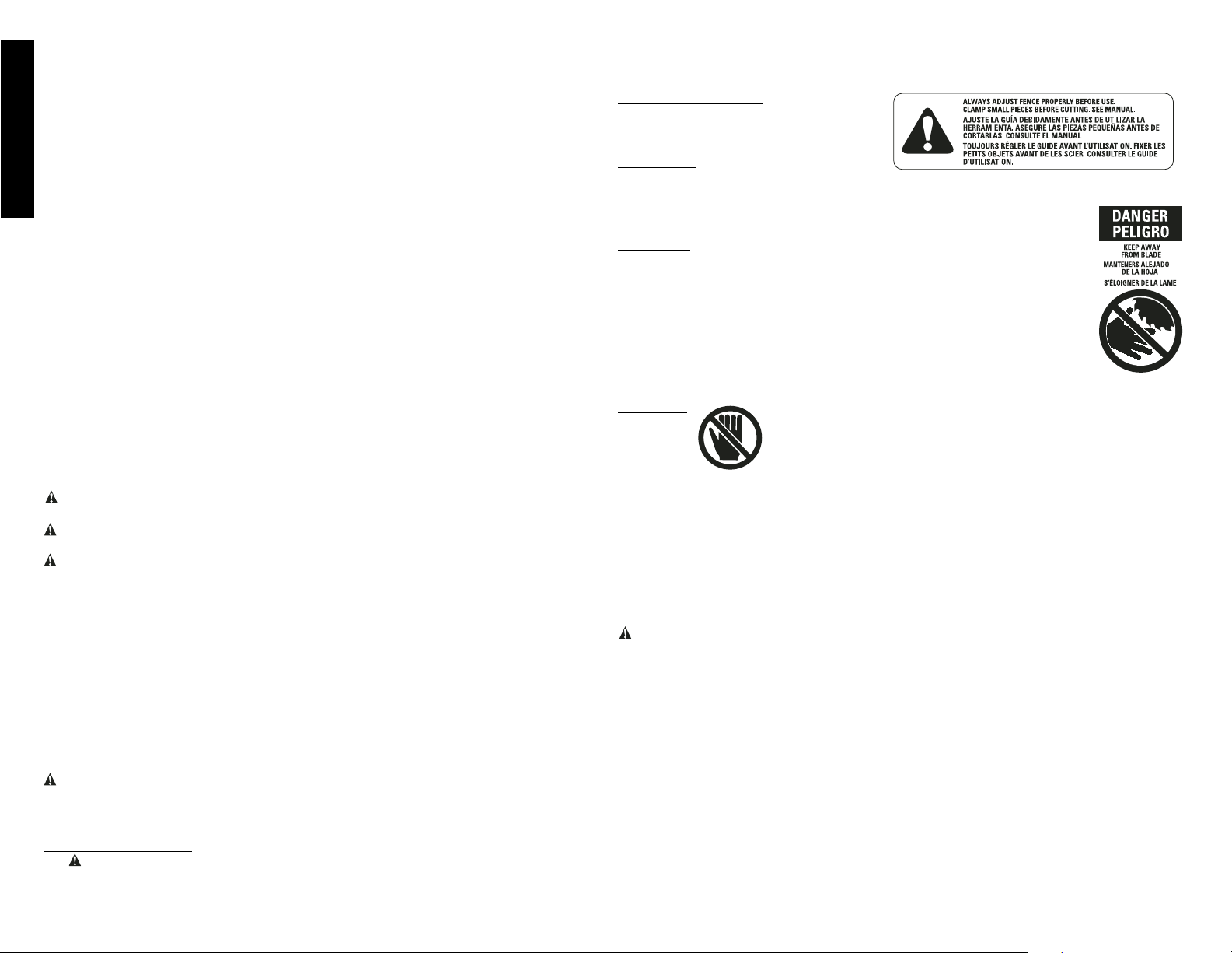
ON MOVING FENCES:
ALWAYS ADJUST FENCE PROPERLY
BEFORE USE. Clamp small pieces
before cutting. See manual.
ON GUARD:
DANGER – KEEP AWAY FROM BLADE.
ON UPPER GUARD:
PROPERLY SECURE BRACKET WITH BOTH SCREWS BEFORE USE.
ON TABLE:
(2 PLACES)
ALWAYS TIGHTEN ADJUSTMENT KNOBS BEFORE USE. KEEP
HANDS 6" FROM PATH OF SAW BLADE.
NEVER PERFORM ANY OPERATION FREEHAND.
NEVER CROSS ARMS IN FRONT OF BLADE.
THINK! YOU CAN PREVENT ACCIDENTS.
DO NOT OPERATE SAW WITHOUT GUARDS IN PLACE. TURN OFF
TOOL, KEEP SAW HEAD DOWN AND WAIT FOR SAW TO STOP
BEFORE MOVING HANDS, WORKPIECE OR CHANGING SETTINGS.
UNPLUG TOOL BEFORE CHANGING BLADE, MOVING OR SERVICING UNIT.
ON BASE:
Electrical Connection
Be sure your power supply agrees with the nameplate marking. 120 volts, AC means that your
saw will operate on alternating current. The switch is suseptible to failure if direct current is
used. A voltage decrease of 10 percent or more will cause a loss of power and overheating. All
D
EWALT tools are factory tested. If this tool does not operate, check the power supply.
Accessories
Recommended accessories for use with your tool are available at extra cost from your local
service center.
CAUTION: The use of any non-recommended accessory such as dado sets, molding cut-
ters, or abrasive wheels may be hazardous.
If you need assistance in locating any accessory, please contact DEWALT Industrial Tool Co.,
701 East Joppa Road, Baltimore, MD 21286 or call 1-800-4-D
EWALT (1-800-433-9258).
Optional Accessories
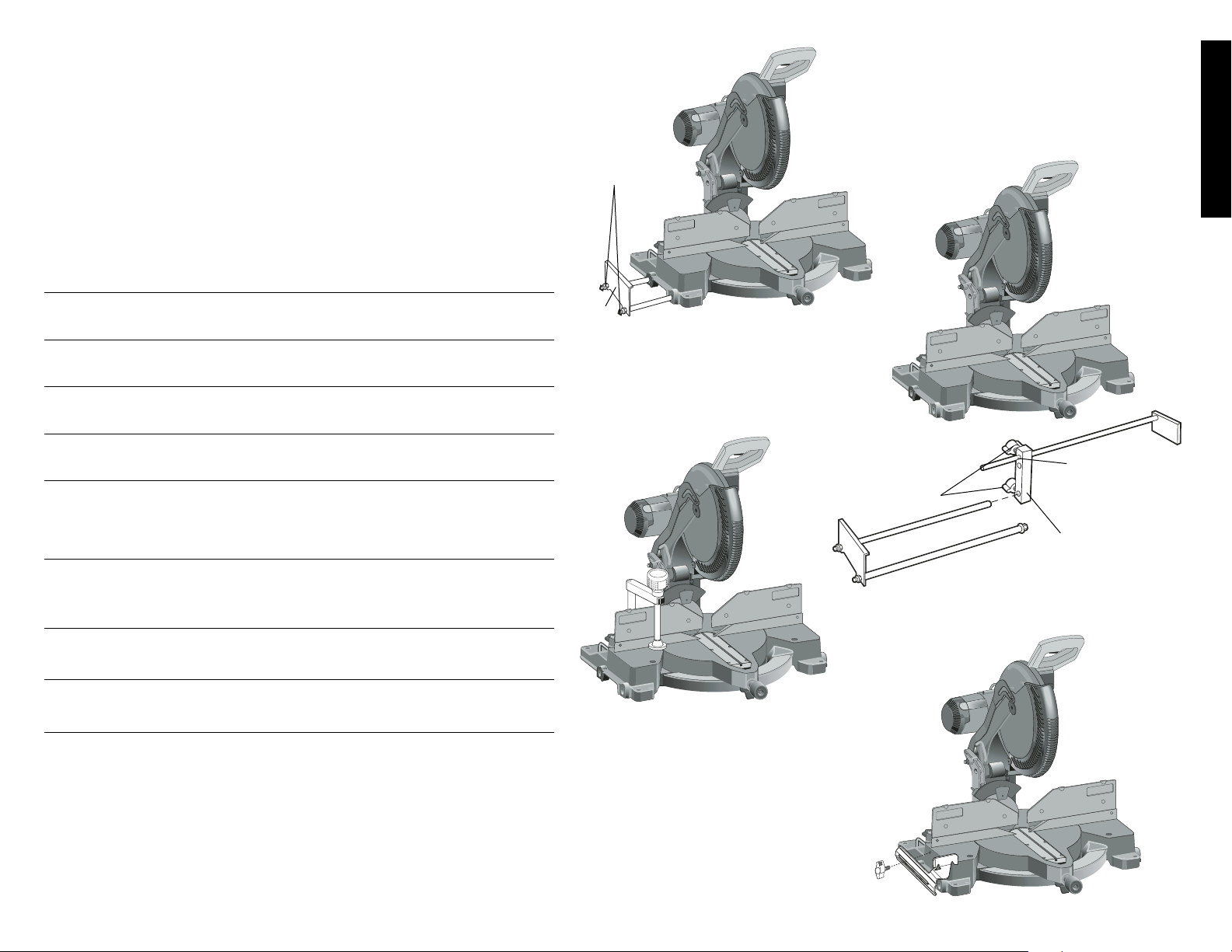
The following accessories, designed for your saw, may be helpful. In some cases, other locally obtained work supports, length stops, clamps, etc., may be more appropriate. Use care in
selecting and using accessories.
Extension, Work Support: DW7080
Used to support long overhanging workpieces, the work support is user assembled. Your saw
table is designed to accept two work supports; one on each side.
Adjustable Length Stop: DW7051
Requires the use of one work support (see drawing). It is used to make repetitive cuts of
the same length from 0 to 42".
Clamp: DW7082
Used for firmly clamping workpiece to the saw table for precision cutting (Page 3).
• DON’T - Attempt to operate on anything but designated voltage.
• DON’T - Operate unless all clamp handles are tight.
• DON’T - Use blades larger or smaller than those which are recommended.
• DON’T - Wedge anything against fan to hold motor shaft.
• DON’T - Force cutting action. (Stalling or partial stalling of motor can cause major damage.
Allow motor to reach full speed before cutting.)
• DON’T - Cut ferrous metals (Those with any iron or steel content) or any masonry.
• DON’T - Use abrasive wheels. The excessive heat and abrasive particles generated by
them will damage the saw.
• DON’T - Allow anyone to stand behind saw.
• DON’T - Apply lubricants to the blade when it’s running.
• DON’T - Place either hand in the blade area when the saw is connected to the power
source.
• DON’T - Use blades rated less than 4800 R.P.M.
• DO NOT - Cut small pieces without clamping. Keep hands 6” or more from blade.
• DON’T - Operate saw without guards in place.
• DON’T - Perform any operation freehand.
• DON’T - Reach around or behind saw blade.
• DON’T - Place hands closer than 6 inches from the saw blade.
• DO NOT - Reach underneath the saw unless it is turned off and unplugged. The saw
blade is exposed on the underside of the saw.
• DO NOT - Move either hand from saw or workpiece or raise arm until blade has stopped.
• DO NOT - Use lubricants or cleaners (particularly spray or aerosol) in the vicinity of the
plastic guard. The polycarbonate material used in the guard is subject to attack by
certain chemicals.
• Never use without kerf plate, and replace when kerf plate is damaged because small chip
accumulation under saw may interfere with saw blade or may cause instability of workpiece when cutting.
CAUTION: Do not connect unit to electrical power source until complete instructions are
read and understood.
CAUTION: Wear appropriate personal hearing protection during use. Under some
conditions and duration of use, noise from this product may contribute to hearing loss.
WARNING: Some dust created by power sanding, sawing, grinding, drilling, and other con-
struction activities contains chemicals known to cause cancer, birth defects or other reproductive harm. Some examples of these chemicals are:
• lead from lead-based paints,
• crystalline silica from bricks and cement and other masonry products, and
• arsenic and chromium from chemically-treated lumber (CCA).
Your risk from these exposures varies, depending on how often you do this type of work. To
reduce your exposure to these chemicals: work in a well ventilated area, and work with
approved safety equipment, such as those dust masks that are specially designed to filter out
microscopic particles.
• Avoid prolonged contact with dust from power sanding, sawing, grinding, drilling,
and other construction activities. Wear protective clothing and wash exposed
areas with soap and water. Allowing dust to get into your mouth, eyes, or lay on the skin
may promote absorption of harmful chemicals.
WARNING: Use of this tool can generate and/or disburse dust, which may cause serious
and permanent respiratory or other injury. Always use NIOSH/OSHA approved respiratory
protection appropriate for the dust exposure. Direct particles away from face and body.
For your convenience and safety, the following warning labels are on your miter saw.
ON MOTOR HOUSING:
WARNING: FOR YOUR OWN SAFETY, READ INSTRUCTION MANUAL BEFORE
OPERATING SAW.
Page 5
3
English
Dust Bag: DW7053 (Included with some models)
Equipped with a zipper for easy emptying, the dust bag will capture the majority of
the sawdust produced. (Not shown)
NOTE: Deflector on dust spout channels debris to ground. Spout has a provision
to attach a vacuum hose to collect sawdust. Lift dust spout to connect hose.
Crown Molding Fence: DW7084
Used for precision cutting of crown molding.
Kerf Plate Blank: DW7055
Used to limit back side tear out of material or as a replacement kerf plate.
SAW BLADES: ALWAYS USE 12" SAW BLADES WITH 1" ARBOR HOLES. SPEED
RATING MUST BE AT LEAST 4800 RPM. Never use a smaller diameter blade. It will
not be guarded properly.
D
EWALT NO. OF BLADE APPLICATION TYPE OF CUT
BLADE TEETH DESC.
RANGE
Series 20 40 Thin Kerf Gen. Purpose Smooth,
Construction Yellow Rim (Trim, Decking, Splinter Free
Coating Framing)
Series 20 60 Thin Kerf Fine Trim Very Smooth,
Construction Yellow Rim Molding Splinter Free
Coating
Series 40 40 Laser Cut Body Gen. Purpose Smooth,
Woodworking Large Carbide (Trim, Decking, Splinter Free
Teeth Framing)
Series 40 60 Laser Cut Body Fine Trim, Very Smooth,
Woodworking Large Carbide Molding Splinter Free
Teeth
Series 40 80 Laser Cut Body Fine Trim Ultra Smooth,
Woodworking Large Carbide Molding Splinter Free
Teeth Decorative
Hardwood
& Plywood
Series 40 80 Laser Cut Body Melamines, Ultra Smooth
Woodworking Large Carbide Veneers, Chip/Splinter
Teeth, Special Laminates Free
Tooth Geometry
Series 40 60 Laser Cut Body Plastics, Corian® Very Smooth
Woodworking Special Tooth and other solid Chip Free
Geometry surface materials
Series 40 80 Laser Cut Body Non-ferrous metals Very Smooth
Woodworking Special Tooth (aluminum, copper, Burr Free
Geometry brass, etc.)
Unpacking Your Saw
Check the contents of your miter saw carton to make sure that you have received all
parts. In addition to this instruction manual, the carton should contain:
1. One No. DW706 miter saw.
2. One D
EWALT 12" dia. saw blade
3. One blade wrench in wrench pocket shown in Figure 2.
4. One DW7053 dustbag (some models)
DW7051
KNOBS
BRACKET
TOP HOLE
(USE FOR
DW706)
LOCKNUTS
END
PLATE
DW7080
DW7082
DW7084
Page 6
4
English
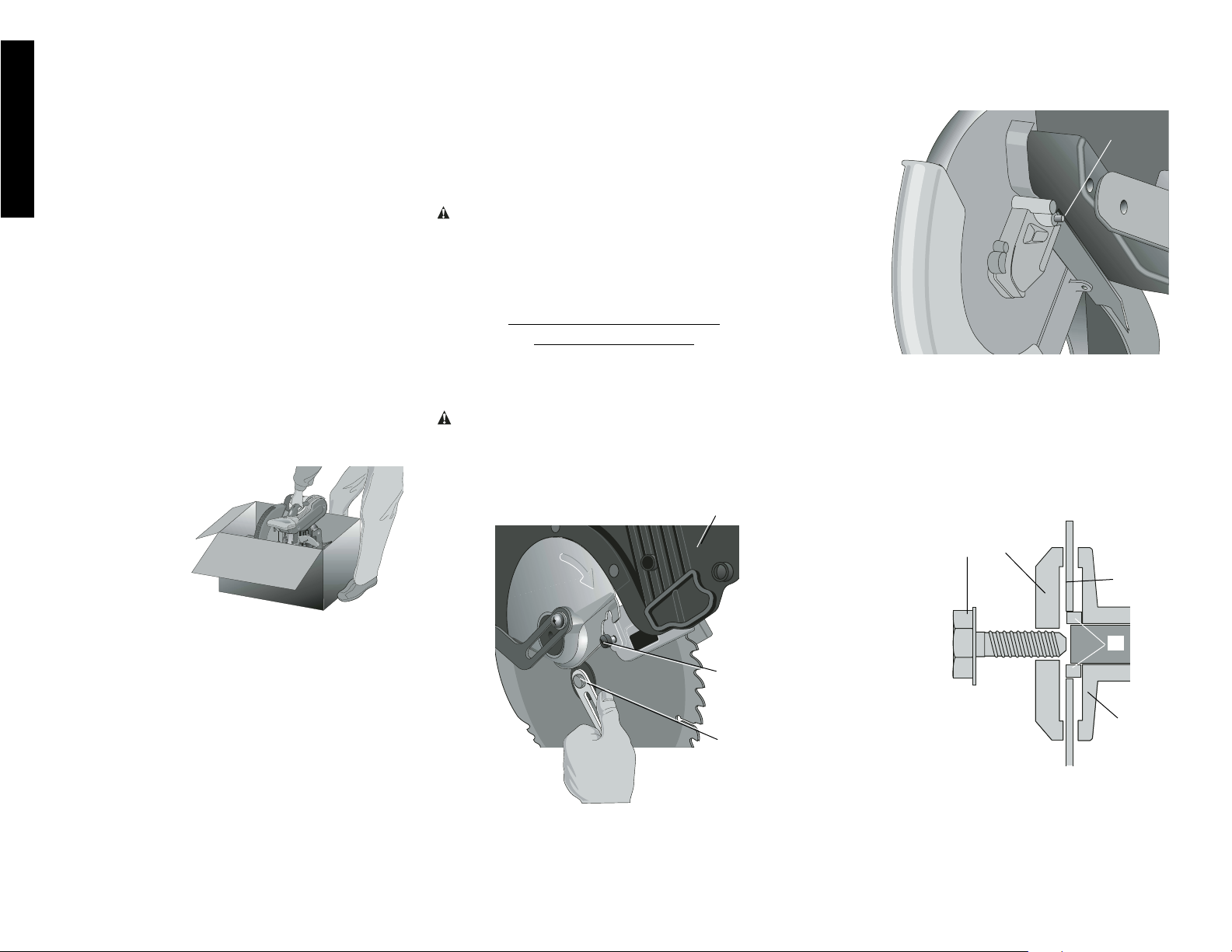
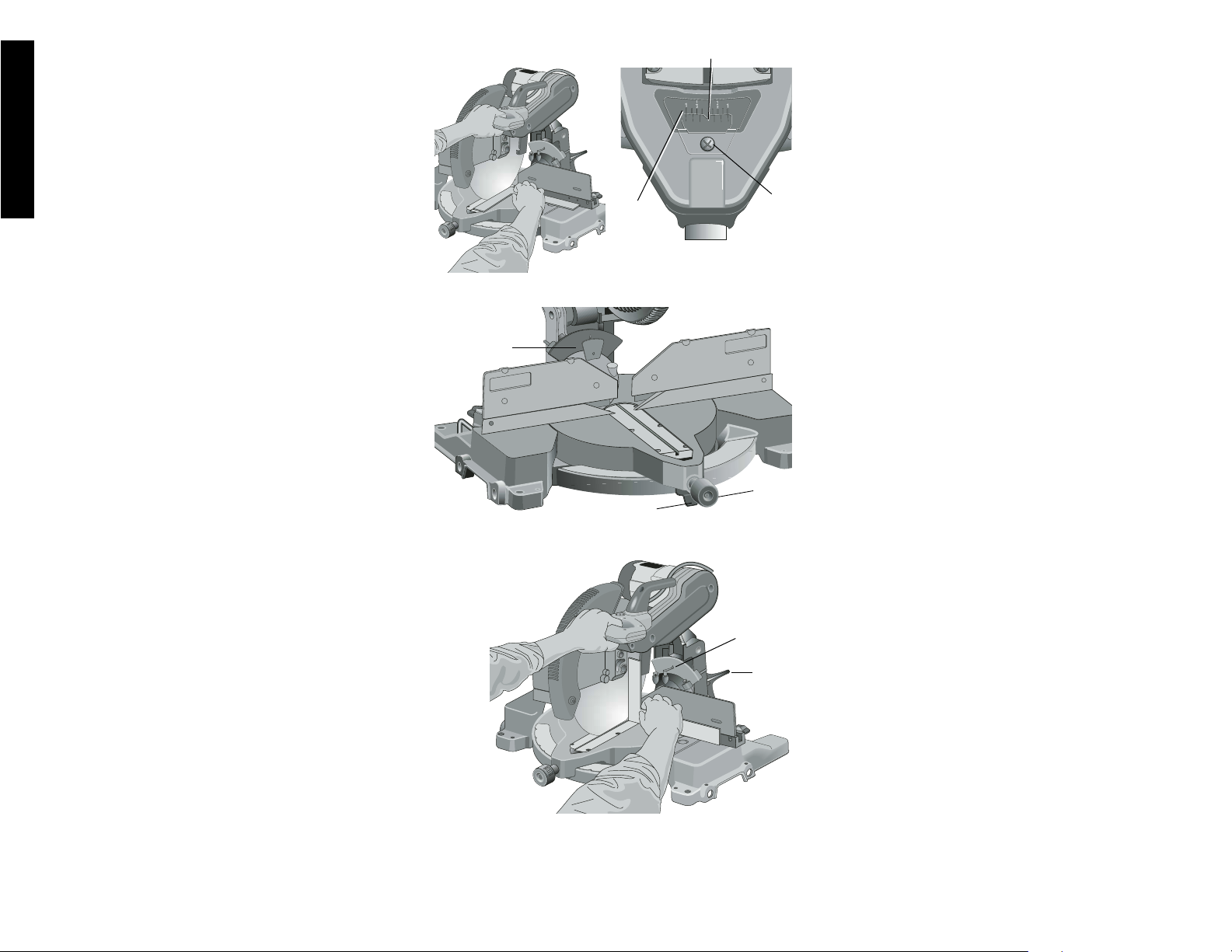
3. Loosen, but do not remove guard bracket screw (B)
until the bracket can be raised far enough to access the
blade screw. Lower guard will remain raised due to the
position of the guard bracket screw.
4. Depress the spindle lock button (C) while carefully
rotating the saw blade by hand until the lock engages.
5. Keeping the button depressed, use the other hand and
the wrench provided (D) to loosen the blade screw.
(Turn clockwise, left-hand threads)
6. Remove the blade screw (E), outer clamp washer (F),
and blade (G). The 1" (25.4mm) blade adapter (H), if
used, and the inner clamp washer (I), may be left on
the spindle.
NOTE: For blades with a blade hole of 5/8" (15.88mm), the
1" (25.4mm) blade adapter is not used.
Installing a Blade
1. Unplug the saw.
2. With the arm raised, the lower guard held open and
the pivot plate raised, place the blade on the spindle,
onto the blade adapter [if using a blade with a 1"
-DETAIL 2-
E
F
G
I
H
C
-DETAIL 1-
Specifications
CAPACITY OF CUT
50˚ miter left and right
48˚ bevel left and right
0˚ miter Max. Height 3.5" Result Width 7.4"
Max. Width 7.9" Result Height 2.9"
45˚ miter Max. Height 3.5" Result Width 5.3"
Max. Width 5.6" Result Height 2.9"
45˚ bevel - Left Max. Height 2.3" Result Width 7.4"
Max. Width 7.9" Result Height 1.9"
45˚ bevel - Right Max. Width 7.9” Result Height 1.2"
Max. Height 1.6" Result Width 7.4”
Your saw is capable of cutting baseboard moldings 0.9” thick
by 6.0” tall on a 45˚ right or left miter.
DRIVE
120 Volt Motor
2200 Watts 15 Amp Motor
4000 RPM Cut Helical Gears
Multi-V Belt Roller Bearings
Automatic Electric Brake Carbide Blade
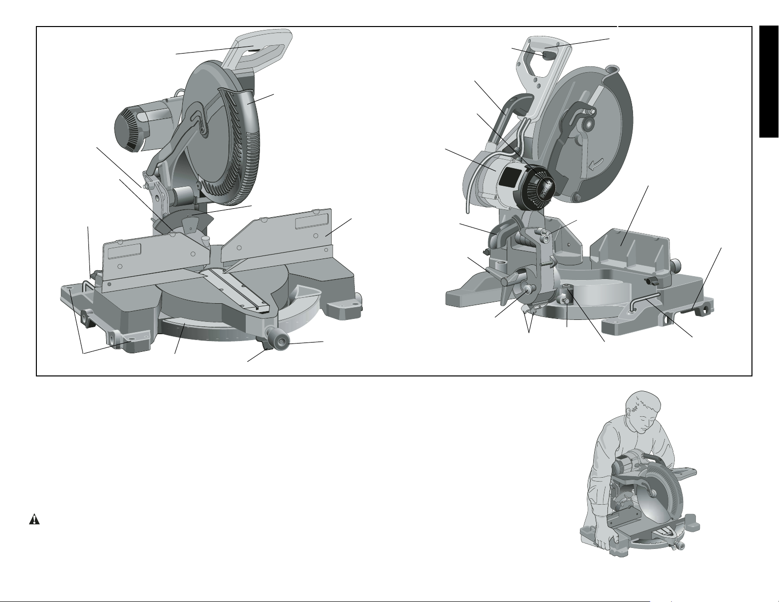
Familiarization
Your miter saw is fully
assembled in the carton. Open the box and
lift the saw out by the
convenient carrying
handle, as shown in
Figure 1.
Place the saw on a
smooth, flat surface
such as a workbench or
strong table.
Examine the two figures on page 5 to become familiar with
the saw and its various parts. The section on adjustments
will refer to these terms and you must know what and where
the parts are.
Press down lightly on the operating handle and pull out the
lock down pin, as shown in Figure 2. Gently release the
downward pressure and hold the arm allowing it to rise to its
full height. Use the lock down pin when carrying the saw from
one place to another. Always use the carrying handle to
transport the saw or the hand indentations shown in Fig. 2.
Bench Mounting
Holes are provided in all four feet to facilitate bench mounting, as shown in Figure 2. (Two different sized holes are provided to accommodate different sizes of screws. Use either
hole, it is not necessary to use both.) Always mount your
saw firmly to a stable surface to prevent movement. To
FIG. 1
enhance the tool’s portability, it can be mounted to a piece
of 1/2" or thicker plywood which can then be clamped to
your work support or moved to other job sites and
reclamped.
NOTE: If you elect to mount your saw to a piece of plywood, make sure that the mounting screws don’t protrude
from the bottom of the wood. The plywood must sit flush on
the work support. When clamping the saw to any work surface, clamp only on the clamping bosses where the mounting screw holes are located. Clamping at any other point
will surely interfere with the proper operation of the saw.
CAUTION: To prevent binding and inaccuracy, be sure
the mounting surface is not warped or otherwise uneven. If
the saw rocks on the surface place a thin piece of material
under one saw foot until the saw sits firmly on the mounting
surface.
IMPORTANT SAFETY
INSTRUCTIONS
Changing or Installing a New Saw
Blade (Fig. 3)
CAUTION:
• Never depress the spindle lock button while the blade is
under power or coasting.
• Do not cut ferrous metal (containing iron or steel) or
masonry or fiber cement product with this miter saw.
Removing the Blade
1. Unplug the saw.
2. Raise the arm to the upper position and raise the lower
guard (A) as far as possible.
A
B
D
FIG. 3
Page 7
5
English
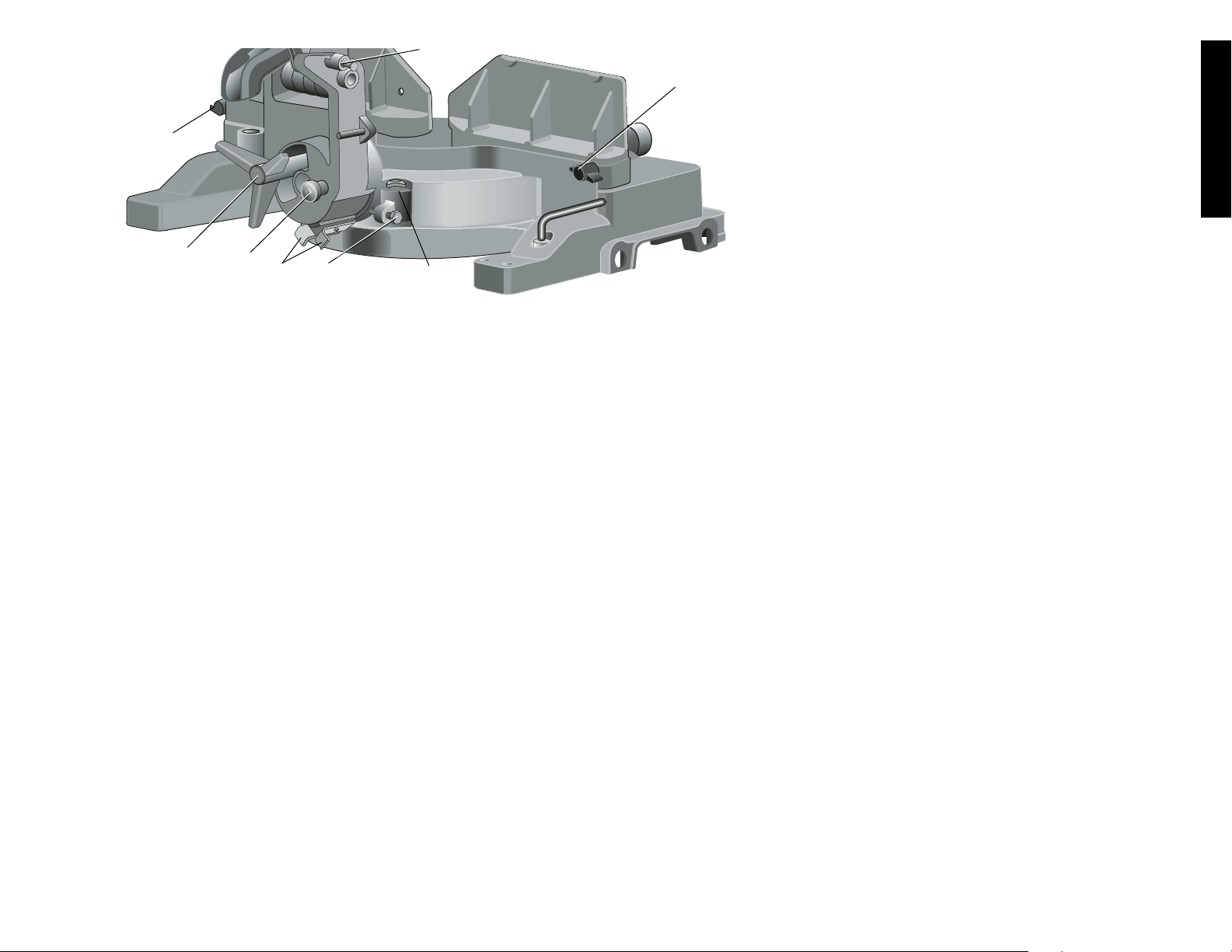
FIG. 2
GUARD
RIGHT SIDE
FENCE
MITER
CLAMP
KNOB
MITER
LATCH
MITER
SCALE
BENCH MOUNTING
HOLES
LEFT SIDE FENCE
CLAMPING KNOB
LOCK DOWN
PIN
OPERATING HANDLE
BEVEL SCALE
FIG. 4
TRIGGER
SWITCH
OPERATING
HANDLE
LEFT SIDE
FENCE
MOTOR
HOUSING
45˚ BEVEL
OVERRIDE
LEVERS
DUST
SPOUT
MOTOR END
CAP
0˚ BEVEL
OVERRIDE
KNOB
LOCK DOWN
PIN
BEVEL STOP–
33.85˚ PAWLS
CARRY HANDLE
BLADE
WRENCH
45˚
BEVEL STOP–
ADJUSTMENT
SCREW
BEVEL
LOCK
KNOB
HAND
INDENTATIONS
0˚ BEVEL STOP
ADJ. SCREW
(25.4mm) diameter blade hole] and against the inner
clamp washer with the teeth at the bottom of the blade
pointing toward the back of the saw.
3. Assemble the outer clamp washer onto the spindle.
4. Install the blade screw and, engaging the spindle lock,
tighten the screw firmly with wrench provided. (Turn
counterclockwise, left-hand threads)
NOTE: When using blades with a 5/8" (15.88mm) diameter
blade hole, the blade adapter will not be used and should be
stored in a safe place for future use.
5. Return the guard bracket to its original position and
firmly tighten the guard bracket screw to hold bracket in
place.
WARNING:
• The guard bracket must be returned to
its original position and the screw tightened before activating the saw.
• Failure to do so may allow the guard to
contact the spinning saw blade resulting in damage to the saw and severe
personal injury.
Transporting the Saw
TURN OFF AND UNPLUG THE MITER SAW BEFORE
ATTEMPTING TO MOVE IT OR MAKE ANY ADJUSTMENTS WHAT SO EVER!
In order to conveniently carry the miter saw from place to
place, a carrying handle has been included on the top of the
saw arm and hand indentations in the base, as shown in
Figure 4.
Page 8
6
English
FIG. 7
FIG. 6
MITER
SCALE
POINTER
J
K
T
To adjust the right 45˚ bevel angle, loosen the bevel lock
handle and pull the bevel stop override knob (Fig. 2) to override the 0˚ bevel stop. When the saw is fully to the right, if
the pointer does not indicate exactly 45˚, turn the right bevel
stop screw (O) until the pointer indicates 45˚.
To adjust the left 45˚ bevel stop, first loosen the bevel lock
handle and tilt the head to the left. If the pointer does not
indicate exactly 45˚, turn the left bevel stop screw until the
pointer reads 45˚.
ADJUSTING THE BEVEL STOP TO 33.85˚ (FIG. 9)
NOTE: Adjust the 33.85˚ bevel angles only after performing
the 0˚ bevel angle and pointer adjustment.
To set the 33.85˚ bevel angle, flip out the stop pawls (P).
Loosen the bevel lock handle (Q) and tilt the head to the left.
If the pointer does not indicate exactly 33.85˚, turn the screw
contacting the pawl until the pointer reads 33.85˚.
To adjust the right 33.85˚ bevel angle, flip out the stop pawl.
Loosen the bevel lock handle and pull the bevel stop override button to override the 0˚ bevel stop. When the saw is
fully to the right, if the pointer does not indicate exactly
33.85˚, turn the screw contacting the pawl until the pointer
indicates 33.85˚.
FENCE ADJUSTMENT
Turn Off and Unplug the Miter Saw
In order that the saw can bevel to a full 48 degrees left or
right, the fences can be adjusted to provide clearance. To
adjust a fence, loosen the plastic knob (Figure 9, R), and
slide the fence outward. Make a dry run with the saw turned
off and check for clearance. Adjust the fence to be as close
to the blade as practical to provide maximum workpiece
support, without interfering with arm up and down movement. Tighten knob securely. When the bevel operations are
complete, don’t forget to relocate the fence.
NOTE: The guide groove of the fences can become clogged
with sawdust. If you notice that it is becoming clogged, use
a stick or some low pressure air to clear the guide groove.
AUTOMATIC ELECTRIC BRAKE
Your saw is equipped with an automatic electric blade brake
which stops the saw blade within 5 seconds of trigger
release. This is not adjustable.
On occasion, there may be a delay after trigger release to
brake engagement. On rare occasions, the brake may not
engage at all and the blade will coast to a stop.
If a delay or “skipping” occurs, turn the saw on and off 4 or
5 times. If the condition persists, have the tool serviced by
an authorized D
EWALT service center.
Always be sure the blade has stopped before removing it
from the kerf. The brake is not a substitute for guards or for
ensuring your own safety by giving the saw your complete
attention.
FIG. 5
FIG. 8
Adjustments
PERFORM ALL ADJUSTMENTS WITH THE MITER
SAW UNPLUGGED
NOTE: Your miter saw is fully and accurately adjusted at the
factory at the time of manufacture. If readjustment due to
shipping and handling or any other reason is required, follow
the steps below to adjust your saw.
Once made, these adjustments should remain accurate.
Take a little time now to follow these directions carefully to
maintain the accuracy of which your saw is capable.
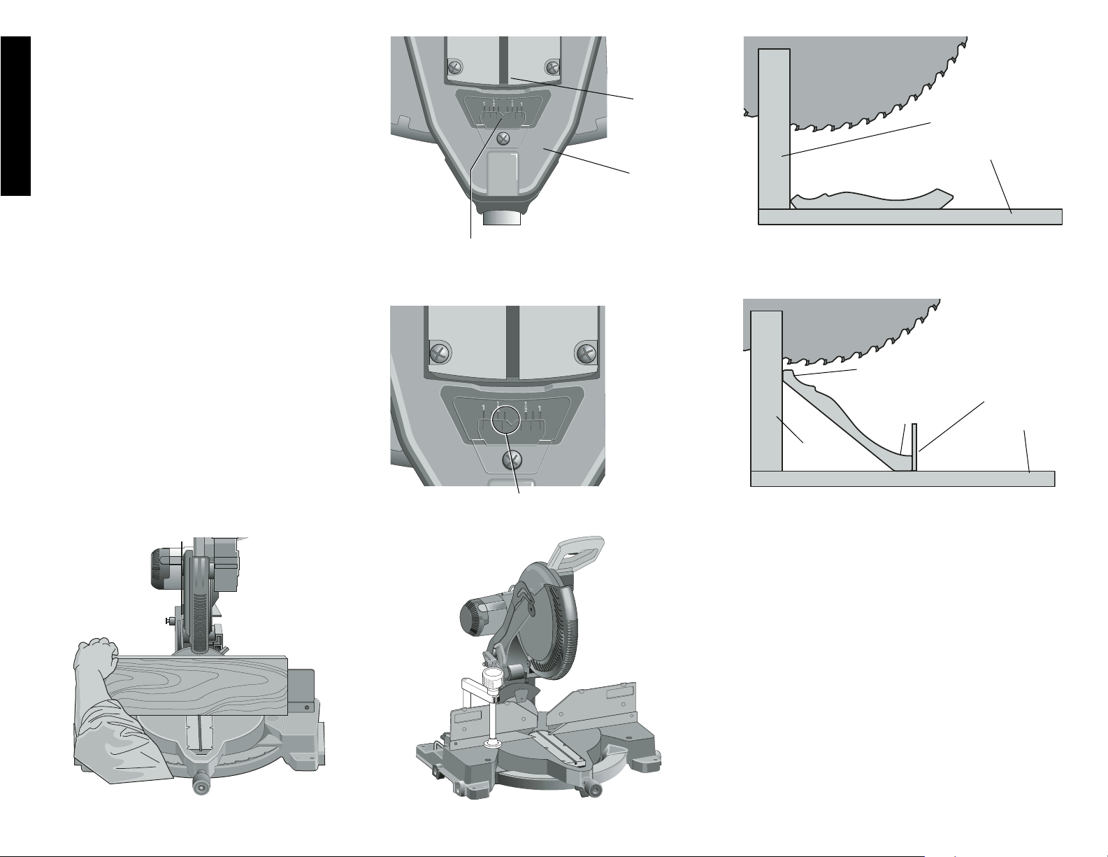
MITER SCALE ADJUSTMENT (FIG. 5)
Place a square against the saw’s fence and blade, as
shown. (Do not touch the tips of the blade teeth with the
square. To do so will cause an inaccurate measurement.)
Loosen the miter clamp knob and swing the miter arm until
the miter latch locks it at the 0 miter position. Do not tighten
the clamp knob. If the saw blade is not exactly perpendicular to the fence, loosen the three screws that hold the miter
scale to the base and move the scale left or right until the
blade is perpendicular to the fence, as measured with the
square. Retighten the three screws. Pay no attention to the
reading of the miter pointer at this time.
MITER POINTER ADJUSTMENT (FIG. 6, 7)
Loosen the miter clamp knob (J) Fig. 7 by turning counterclockwise and squeeze the miter latch (K) to move the miter
arm to the zero position. With the miter clamp knob loose
allow the miter latch to snap into place as you rotate the
miter arm to zero. Observe the pointer and miter scale
through the viewing opening shown in Figure 6. If the pointer does not indicate exactly zero, loosen the screw holding
the pointer in place, reposition the pointer and tighten the
screw.
BEVEL SQUARE TO TABLE (FIG. 8)
To align the blade square to the rotary table, lock the arm in
the down position. Place a square against the blade taking
care to not have the square on top of a tooth. Loosen the
bevel lock knob (L) and ensure the arm is firmly against the
0˚ bevel stop. Move the 0˚ bevel stop adjusting screw as
necessary so that the blade is at zero degrees bevel to the
table.
BEVEL POINTER (FIG. 8)
If the bevel pointer (M) does not indicate zero, loosen the
screw that holds it in place and move the pointer as necessary. Do not remove the steel plate in front of the bevel
pointer. This plate prevents wood resin from accumulating
on the bevel scale during use.
ADJUSTING THE BEVEL STOP TO 45˚ LEFT OR RIGHT
(FIG. 9)
NOTE: Adjust the 45˚ bevel angles only after performing the
0˚ bevel angle and pointer adjustment. Ensure the 45˚ bevel
override levers (N) are pushed inward to obtain an accurate
adjustment.
POINTER
ADJUST.
SCREW
L
M
Page 9
7
English
FIG. 9
GUARD ACTUATION AND VISIBILITY
The blade guard on your saw has been designed to automatically raise when the arm is brought down and to lower
over the blade when the arm is raised.
The guard can be raised by hand when installing or removing saw blades or for inspection of the saw. NEVER RAISE
THE BLADE GUARD MANUALLY UNLESS THE SAW IS
TURNED OFF.
NOTE: Certain special cuts of large material will require that
you manually raise the guard. See page 11.
The front section of the guard is louvered for visibility
while cutting. Although the louvers dramatically reduce flying debris, they are openings in the guard and safety
glasses should be worn at all times when viewing through
the louvers.
Brushes
DISCONNECT PLUG FROM POWER SUPPLY
Inspect carbon brushes regularly by unplugging tool, removing the motor end cap (Fig. 2), lift the brush spring and withdraw the brush assembly. Keep brushes clean and sliding
freely in their guides. Always replace a used brush in the
same orientation in the holder as it was prior to its removal.
Carbon brushes have varying symbols stamped into their
sides, and if the brush is worn down to approximately 1/2
inch, the spring will no longer exert pressure and they must
be replaced. Use only identical D
EWALT brushes. Use of
the correct grade of brush is essential for proper operation
of electric brake. New brush assemblies are available at
D
EWALT service centers. The tool should be allowed to “run
in” (run at no load) for 10 minutes before use to seat new
brushes. The electric brake may be erratic in operation until
the brushes are properly seated (worn in). Always replace
the brush inspection cap after inspection or servicing the
brushes.
While “running in” DO NOT TIE, TAPE, OR OTHERWISE
LOCK THE TRIGGER SWITCH ON. HOLD BY HAND
ONLY.
Controls
Your compound miter saw has several main controls, which
will be discussed briefly here. For more information on these
controls, see the respective sections later in the manual.
MITER CONTROL (FIG. 7)
The miter lock/adjustment lever and trigger allows you to
miter your saw 50˚ left and right. To miter the saw, loosen
the miter lock handle (J) by rotating it counterclockwise,
squeeze the detent trigger (K) and set the miter angle
desired on the miter scale. Tighten the miter lock handle by
rotating it clockwise.
TRIGGER SWITCH
The trigger switch (Fig. 2) turns your saw on and off. A hole
is provided in the trigger for insertion of a padlock to secure
the saw.
BEVEL LOCK (FIG. 9)
The bevel lock handle (Q) allows you to bevel the saw 48˚
left or right. To loosen the handle and adjust the bevel setting, turn the handle counterclockwise, the saw head bevels
easily to the left or to the right once the 0˚ bevel override
knob (S) is pulled. To tighten, turn the handle clockwise.
Bevel degree markings are on the bottom front of the saw
arm. (Fig. 7, T)
0˚ BEVEL OVERRIDE (FIG. 9)
The bevel stop override (S) allows you to bevel the saw to
the right past the 0˚ mark.
The saw will automatically stop at 0˚ when brought up from
the left. To move past 0˚ to the right, pull the bevel stop
knob. The stop knob can be locked out by pulling the knob
out and rotating it 180˚.
Q
S
R
R
P
U
O
45˚ BEVEL STOP OVERRIDES (FIG. 9)
The bevel stop overrides are held secure with their attachment screw to prevent inadvertent movement. Use the bit
on the blade wrench to loosen the attachment screw. This
allows the slides, to be pulled outward and the saw head to
pivot past the 45˚ mark. Be sure to retighten the attachment
screw when finished.
33.85˚ BEVEL STOPS (FIG. 9)
The two pawls (P) are used to stop the saw head bevel setting at 33.85˚. This setting is used primarily for cutting crown
moldings laid flat on the table.
HEAD DOWNLOCK PIN (FIG. 9)
To lock the saw head in the down position, push the head
down, push the pin (U) in and release the saw head. This
will hold the saw head safely down for moving the saw from
place to place. To release, press the saw head down and
pull the pin out.
Operation
Plug the saw into any household 60 Hz power source. Refer
to the nameplate for voltage. Be sure the cord will not interfere with your work.
SWITCH
To turn the saw on, depress the trigger switch. To turn the
tool off, release the switch. Allow the blade to spin up to full
operating rpm before making the cut. Release the trigger
switch and allow the brake to stop the blade before raising
the saw head. There is no provision for locking the switch
on, but a hole is provided in the trigger for insertion of a padlock to lock the saw off.
CUTTING WITH YOUR SAW
NOTE: Although this saw will cut wood and many non-
ferrous materials, we will limit our discussion to the cutting
of wood only. The same guidelines apply to the other materials. DO NOT CUT FERROUS (IRON AND STEEL)
MATERIALS OR MASONRY WITH THIS SAW. Do not use
any abrasive blades.
CROSSCUTS
Cutting of multiple pieces is not recommended but can be
done safely by ensuring that each piece is held firmly
against the table and fence. A crosscut is made by cutting
wood across the grain at any angle. A straight crosscut is
made with the miter arm at the zero degree position. Set the
miter arm at zero, hold the wood on the table and firmly
against the fence. Turn on the saw by squeezing the trigger.
When the saw comes up to speed (about 1 second) lower
the arm smoothly and slowly to cut through the wood. Let the
blade come to a full stop before raising arm.
Miter crosscuts are made with the miter arm at some angle
other than zero. This angle is often 45 degrees for making
corners, but can be set anywhere from zero to 50 degrees
left or right. After selecting the desired miter angle, be sure
to tighten the miter clamp knob. Make the cut as described
above.
N
Page 10
8
English
BEVEL CUTS
A bevel cut is a crosscut made with the saw blade at a
bevel to the wood. In order to set the bevel, loosen the
bevel clamp knob and move the saw to the left as desired.
(It is necessary to move the fence to allow clearance).
Once the desired bevel angle has been set, tighten the
bevel clamp knob firmly.
Bevel angles can be set from 48 degrees right to
48 degrees left and can be cut with the miter arm set
between zero and 50 degrees right or left. At some extreme
angles, the right or left side fence might have to be
removed. To remove the left or right fence, unscrew the
knobs several turns and slide the fence out.
QUALITY OF CUT
The smoothness of any cut depends on a number of variables.
Things like material being cut, blade type, blade sharpness and
rate of cut all contribute to the quality of the cut.
When smoothest cuts are desired for molding and other
precision work, a sharp (60 tooth carbide) blade and a
slower, even cutting rate will produce the desired results.
Ensure that material does not creep while cutting, clamp it
securely in place. Always let the blade come to a full stop
before raising arm.
If small fibers of wood still split out at the rear of the workpiece, stick a piece of masking tape on the wood where the
cut will be made. Saw through the tape and carefully
remove tape when finished.
For varied cutting applications, refer to the list of recommended saw blades for your saw and select the one that
best fits your needs (Page 3).
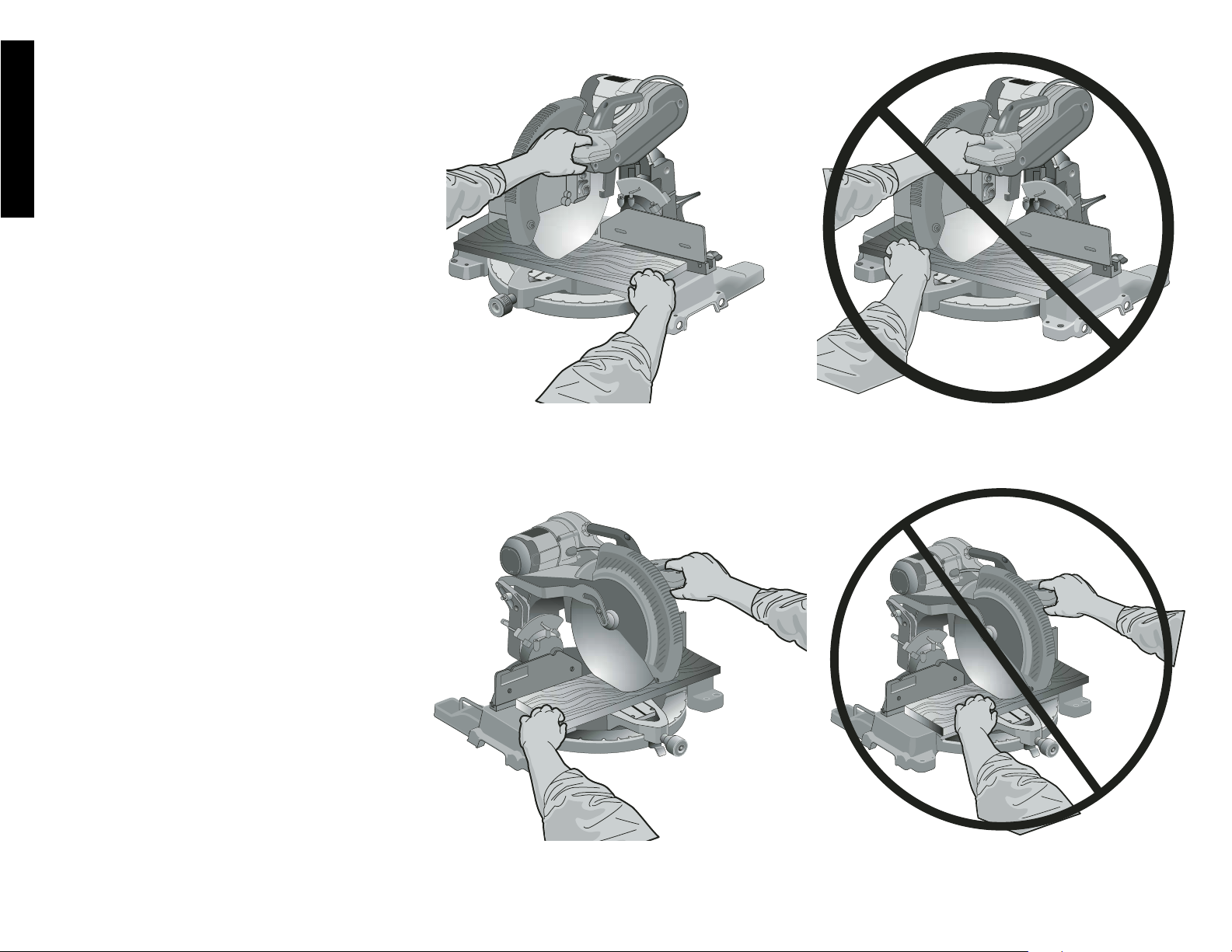
BODY AND HAND POSITION (FIG. 10)
Proper positioning of your body and hands when operating
the miter saw will make cutting easier, more accurate and
safer. Never place hands near cutting area. Place hands no
closer than 6" from the blade. Hold the workpiece tightly to
the table and the fence when cutting. Keep hands in position until the trigger has been released and the blade has
completely stopped. ALWAYS MAKE DRY RUNS
(UNPOWERED) BEFORE FINISH CUTS SO THAT YOU
CAN CHECK THE PATH OF THE BLADE. DO NOT
CROSS HANDS, AS SHOWN IN FIGURE 10A.
Keep both feet firmly on the floor and maintain proper balance. As you move the miter arm left and right, follow it and
stand slightly to the side of the saw blade. Sight through the
guard louvers when following a pencil line.
CLAMPING THE WORKPIECE
Turn Off and Unplug Saw
If you cannot secure the workpiece on the table and against
the fence by hand, (irregular shape, etc.) or your hand
would be less than 6" from the blade, a clamp or other fixture must be used.
IMPROPER CUT
IMPROPER CUT
PROPER CUT
FIG. 10
PROPER CUT
FIG. 10A
FIG. 10B
FIG. 10C
Page 11
9
English
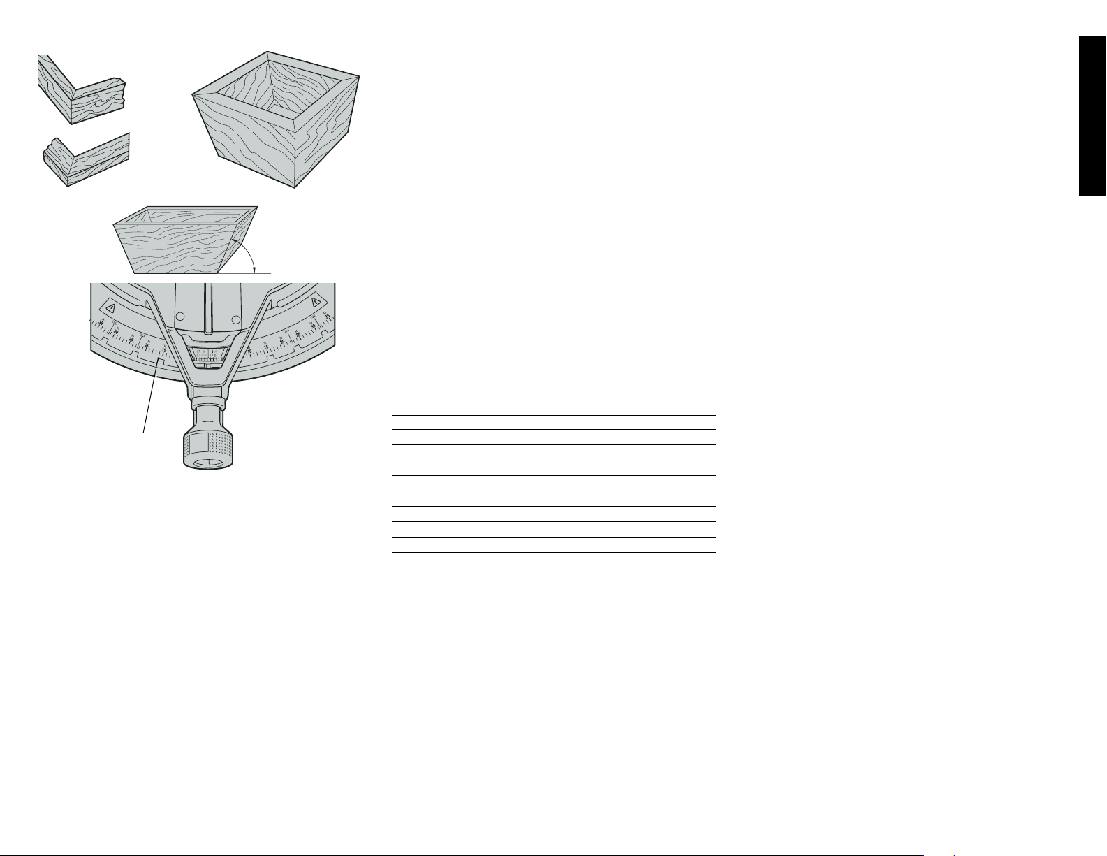
Your saw is the perfect tool for mitering corners like the one
shown in Figure 12. Sketch A in Figure 11 shows a joint
made by using the bevel adjustment to bevel the edges of
the two boards at 45 degrees each to produce a 90 degree
corner. For this joint the miter arm was locked in the zero
position and the bevel adjustment was locked at 45 degrees.
The wood was positioned with the broad flat side against the
table and the narrow edge against the fence. The cut could
also be made by mitering right and left with the broad surface against the fence.
CUTTING TRIM MOLDING AND OTHER FRAMES
Sketch B in Figure 11 shows a joint made by setting the
miter arm at 45 degrees to miter the two boards to form a 90
degree corner. To make this type of joint, set the bevel
adjustment to zero and the miter arm to 45 degrees. Once
again, position the wood with the broad flat side on the table
and the narrow edge against the fence.
The two sketches in Figure 11 are for four side objects only.
As the number of sides changes, so do the miter and bevel
angles. The chart below gives the proper angles for a variety of shapes.
(The chart assumes that all sides are of equal length.) For a
shape that is not shown in the chart, use the following formula. 180 degrees divided by the number of sides equals
the miter (if the material is cut vertically) or bevel angle (if the
material is cut laying flat).
- EXAMPLES -
NO. SIDES ANGLE MITER OR BEVEL
445°
536°
630°
7 25.7°
8 22.5°
920°
10 18°
CUTTING COMPOUND MITERS
A compound miter is a cut made using a miter angle and a
bevel angle at the same time. This is the type of cut used to
make frames or boxes with slanting sides like the one shown
in Figure 13.
NOTE: If the cutting angle varies from cut to cut, check that
the bevel clamp knob and the miter lock knob are securely
tightened. These knobs must be tightened after making any
changes in bevel or miter.
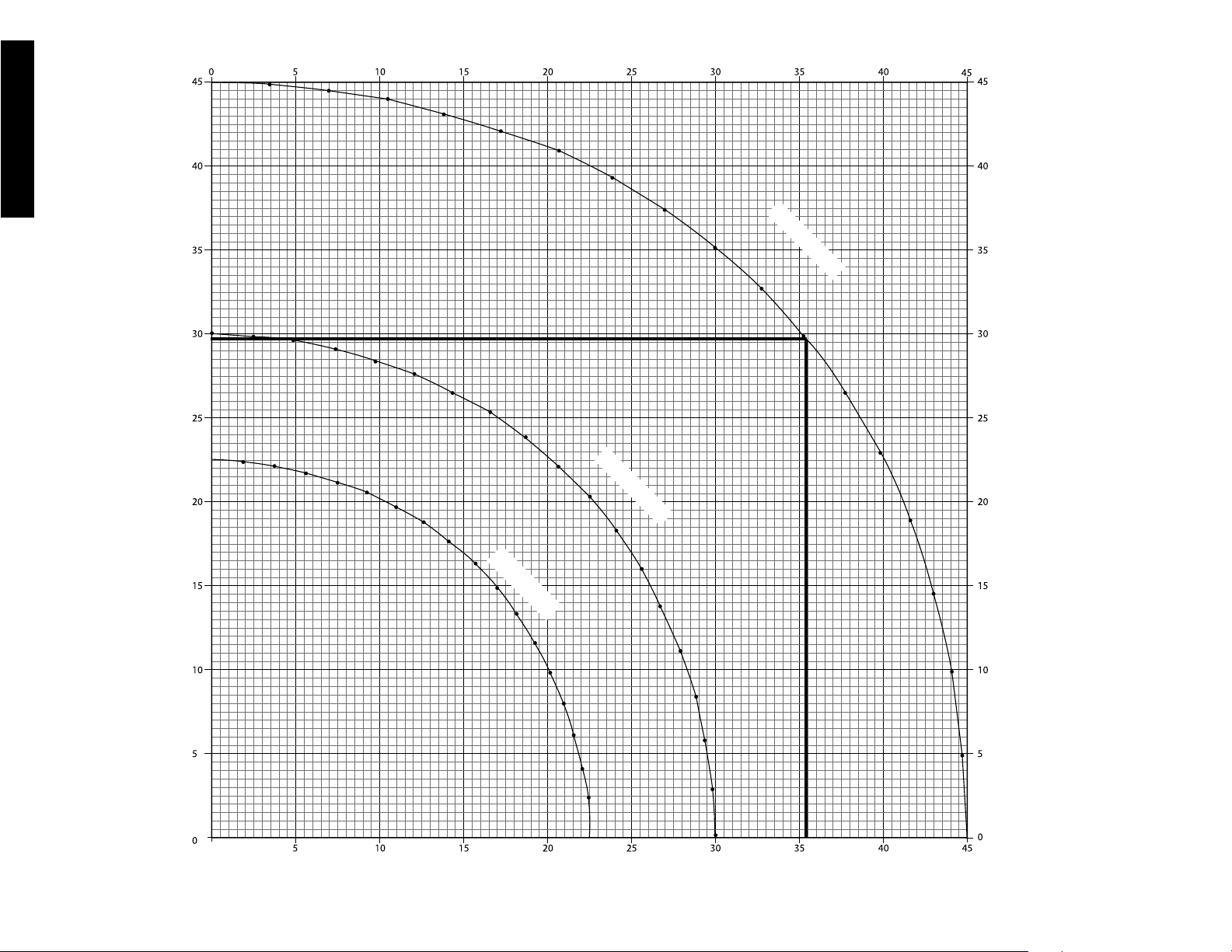
The chart shown on page 12 will assist you in selecting the
proper bevel and miter settings for common compound miter
cuts. To use the chart, select the desired angle “A” (Figure
13) of your project and locate that angle on the appropriate
arc in the chart. From that point follow the chart straight
down to find the correct bevel angle and straight across to
find the correct miter angle.
Set your saw to the prescribed angles and make a few trial
cuts. Practice fitting the cut pieces together until you develop a feel for this procedure and feel comfortable with it.
Example: To make a 4 sided box with 26° exterior angles
(Angle A, Figure 13), use the upper right arc. Find 26° on the
arc scale. Follow the horizontal intersecting line to either side
to get miter angle setting on saw (42°). Likewise, follow the
vertical intersecting line to the top or bottom to get the bevel
angle setting on the saw (18°). Always try cuts on a few scrap
pieces of wood to verify settings on saw.
VERNIER SCALE
Your saw is equipped with a vernier scale for added precision. The vernier scale allows you to accurately set miter
angles to the nearest 1/4 degree. To use the vernier scale
follow the steps listed below.
(As an example, let’s assume that the angle you want to
miter is 24 1/4 degree right).
1. Turn off miter saw.
2. Set the miter angle to the nearest whole degree desired
by aligning the center mark in the vernier scale, shown
in Figure V1, with the whole degree number etched in
the miter scale. Examine Figure V2 closely; the setting
shown is 24 degrees right miter.
3. To set the additional 1/4 degree, squeeze the miter arm
lock and carefully move the arm to the RIGHT until the
1/4 degree vernier mark aligns with the CLOSEST
degree mark on the miter scale. In our example, the
closest degree mark on the miter scale happens to be
25 degrees. Figure V2 shows a setting of 24-1/4
degrees right miter.
For settings that require partial degrees (1/4, 1/2, 3/4
degrees) align the desired vernier mark with the CLOSEST
degree mark on the miter scale, as described below (The
plastic vernier plate is inscribed with marks for 1/4, 1/2, 3/4
and 1 degrees. Only the 1/2 degree and the 1 degree are
numerically labeled.)
WHEN MITERING TO THE RIGHT
To increase the miter angle when mitering to the right, move
the arm to align the appropriate vernier mark with the closest mark on the miter scale to the right. To decrease the
miter angle when mitering to the right, move the arm to align
the appropriate vernier mark with the closest mark on the
miter scale to the left.
WHEN MITERING TO THE LEFT
To increase the miter angle when mitering to the left, move
the arm to align the appropriate vernier mark with the closest mark on the miter scale to the left. To decrease the miter
angle when mitering to the left, move the arm to align the
appropriate vernier mark with the closest mark on the miter
scale to the right.
FIG. 11
FIG. 12
FIG. 13
A
B
ANGLE “A”
FIG. 14
MITER
SCALE
For best results use the DW7082 clamp made for use with
your saw. It is available for purchase at your local retailer or
D
EWALT service center.
Other aids such as spring clamps, bar clamps or C-clamps
may be appropriate for certain sizes and shapes of material. Use care in selecting and placing these clamps. Take
time to make a dry run before making the cut. The left or
right fence will slide from side to side to aid in clamping.
SUPPORT FOR LONG PIECES
Turn Off and Unplug Saw
ALWAYS SUPPORT LONG PIECES
For best results, use the DW7080 extension work support to
extend the table width of your saw. Available from your dealer at extra cost. Support long workpieces using any convenient means such as sawhorses or similar devices to keep
the ends from dropping.
CUTTING PICTURE FRAMES, SHADOW BOXES AND
OTHER FOUR SIDED PROJECTS
To best understand how to make the items listed here, we
suggest that you try a few simple projects using scrap wood
until you develop a “FEEL” for your saw.
Page 12
10
English
FIG. V1
FIG. V2
MITER ARM
CENTER MARK ON VERNIER SCALE ALIGNS
WITH DESIRED WHOLE ANGLE ON MITER SCALE
(24° RIGHT MITER)
1/4° VERNIER MARK ALIGNS WITH CLOSET WHOLE
DEGREE MARK ON MITER SCALE (24-1/4° RIGHT MITER)
KERF
PLATE
CUTTING BASE MOLDING
ALWAYS MAKE A DRY RUN WITHOUT POWER BEFORE
MAKING ANY CUTS.
Straight 90 degree cuts:
Position the wood against the fence and hold it in place
as shown in Figure 15. Turn on the saw, allow the blade
to reach full speed and lower the arm smoothly through
the cut.
CUTTING BASE MOLDING UP TO 6" HIGH VERTICALLY
AGAINST THE FENCE
Position material as shown in Figure 15.
All cuts made with the back of the molding against the fence
and bottom of the molding against the base.
INSIDE CORNER:
Left side
1. Miter left 45°
2. Save left side of cut
Right side
1. Miter Right 45°
2. Save right side of cut
OUTSIDE CORNER:
Left side
1. Miter right at 45°
2. Save left side of cut
Right side
1. Miter left at 45°
2. Save right side of cut
Material up to 6" can be cut as described above.
CUTTING CROWN MOLDING
Your miter saw is better suited to the task of cutting crown
molding than any tool made. In order to fit properly, crown
FIG. 16
FIG. 17
FENCE
TABLE
CROWN MOLDING FLAT ON TABLE AND
AGAINST FENCE
CROWN MOLDING BETWEEN FENCE AND TABLE
TABLE
FENCE
BOTTOM SIDE
OF MOLDING
TOP SIDE OF
MOLDING
FIG. 17A
DW 7084 CROWN
MOLDING FENCE
molding must be compound mitered with extreme accuracy.
The two flat surfaces on a given piece of crown molding are
at angles that, when added together, equal exactly 90
degrees. Most, but not all, crown molding has a top rear
angle (the section that fits flat against the ceiling) of 52
degrees and a bottom rear angle (the part that fits flat
against the wall) of 38 degrees.
Your miter saw has special pre-set miter latch points at
31.62 degrees left and right for cutting crown molding at the
proper angle and bevel stop pawls at 33.85˚ left and right.
There is also a mark on the Bevel scale at 33.85 degrees.
The chart on page 11 gives the proper settings for cutting
crown molding. (The numbers for the miter and bevel settings are very precise and are not easy to accurately set on
your saw.) Since most rooms do not have angles of precisely 90 degrees, you will have to fine tune your settings
anyway.
FIG. 15
Page 13
11
English
PRETESTING WITH SCRAP MATERIAL IS EXTREMELY
IMPORTANT!
INSTRUCTIONS FOR CUTTING CROWN MOLDING
LAYING FLAT AND USING THE COMPOUND FEATURES
1. Molding laying with broad back surface down flat on
saw table (Figure 17).
2. The settings below are for All Standard (U.S.) crown
molding with 52° and 38° angles.
BEVEL SETTING TYPE OF CUT
LEFT SIDE, INSIDE CORNER:
33.85° Left 1. Top of molding against fence
2. Miter table set right 31.62°
3. Save left end of cut
RIGHT SIDE, INSIDE CORNER:
33.85° Right 1. Top of molding against fence.
2. Miter table set at left 31.62°
3. Save right end of cut
LEFT SIDE, OUTSIDE CORNER:
33.85° Right 1. Top of molding against fence.
2. Miter table set at left 31.62°
3. Save left end of cut
RIGHT SIDE, OUTSIDE CORNER:
33.85° Left 1. Top of molding against fence
2. Miter table set right 31.62°
3. Save right end of cut
When setting bevel and miter angles for all compound
miters, remember that:
The angles presented for crown moldings are very
precise and difficult to set exactly. Since they can
easily shift slightly and very few rooms have exactly
square corners, all settings should be tested on scrap
molding.
PRETESTING WITH SCRAP MATERIAL IS
EXTREMELY IMPORTANT!
ALTERNATIVE METHOD FOR CUTTING CROWN
MOLDING
Place the molding on the table at an angle between the
fence and the saw table, as shown in Figure 17A. Use of the
crown molding fence accessory (DW7084) is highly recommended because of its degree of accuracy and convenience. The crown molding fence accessory is available for
purchase from your local dealer.
The advantage to cutting crown molding using this method is
that no bevel cut is required. Minute changes in the miter
angle can be made without affecting the bevel angle. This
way, when corners other than 90 degrees are encountered,
the saw can be quickly and easily adjusted for them. Use the
crown molding fence accessory to maintain the angle at
which the molding will be on the wall.
FIG. 18
BLADE
FENCE
RIGHT
FIG. 19
BLADE
FENCE
WRONG
INSTRUCTIONS FOR CUTTING CROWN MOLDING ANGLED
BETWEEN THE FENCE AND BASE OF THE SAW FOR ALL
CUTS:
1. Angle the molding so the bottom of the molding (part
which goes against the wall when installed) is against the
fence and the top of the molding is resting on the base of
the saw, as shown in Figure 17A.
2. The angled “flats” on the back of the molding must rest
squarely on the fence and base of the saw.
INSIDE CORNER:
Left side
1. Miter right at 45°
2. Save the right side of cut
Right side
1. Miter left at 45°
2. Save left side of cut
OUTSIDE CORNER:
Left side
1. Miter left at 45°
2. Save right side of cut
Right side
1. Miter right at 45°
2. Save left side of cut
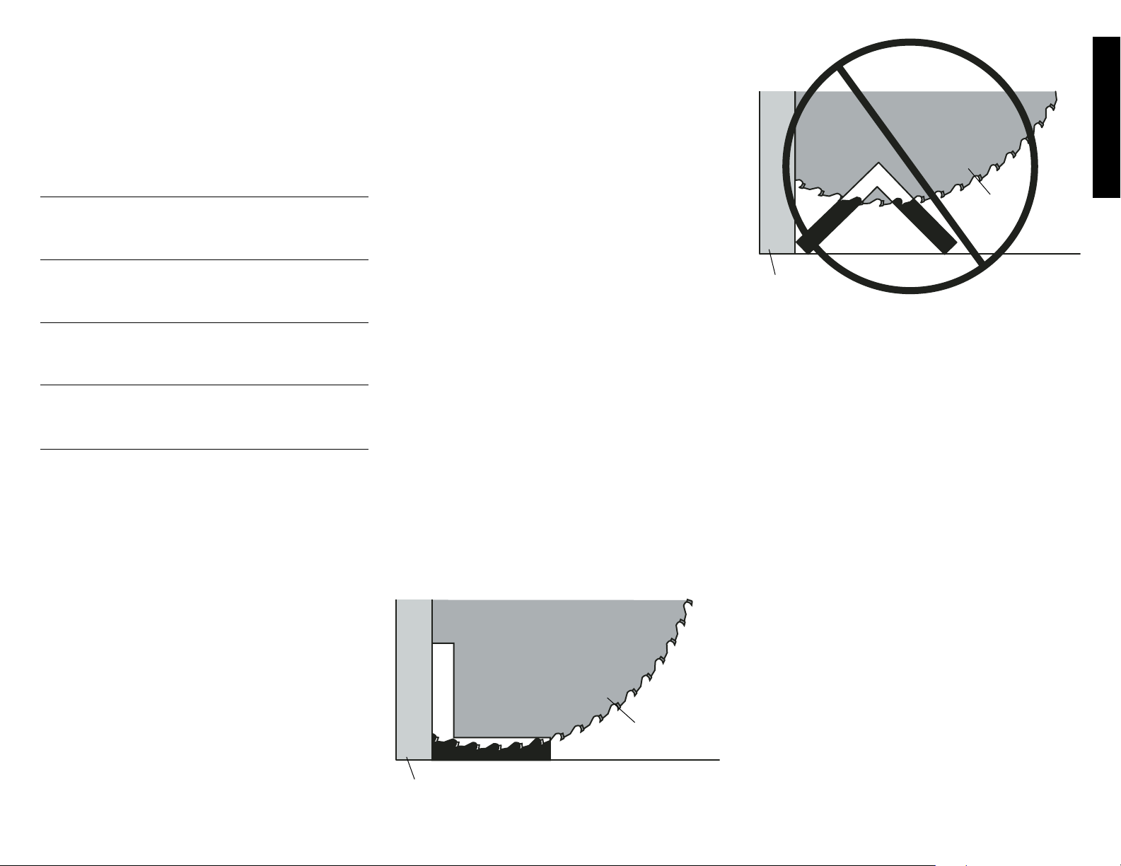
Special Cuts
NEVER MAKE ANY CUT UNLESS THE MATERIAL IS
SECURED ON THE TABLE AND AGAINST THE FENCE.
Aluminum Cutting:
ALWAYS USE THE APPROPRIATE SAW BLADE MADE
ESPECIALLY FOR CUTTING ALUMINUM. These are
available at your local D
EWALT retailer or DEWALT service
center. Certain workpieces, due to their size, shape or
surface finish, may require the use of a clamp or fixture to
prevent movement during the cut. Position the material so
that you will be cutting the thinnest cross section, as shown
in Figure 18. Figure 19 illustrates the wrong way to cut these
extrusions. Use a stick wax cutting lubricant when cutting
aluminum. Apply the stick wax directly to the saw blade
before cutting. Never apply stick wax to a moving blade.
The wax, available at most hardware stores and industrial
mill supply houses, provides proper lubrication and keeps
chips from adhering to the blade.
Be sure to properly secure workpiece. Refer to page 3 for
correct saw blade.
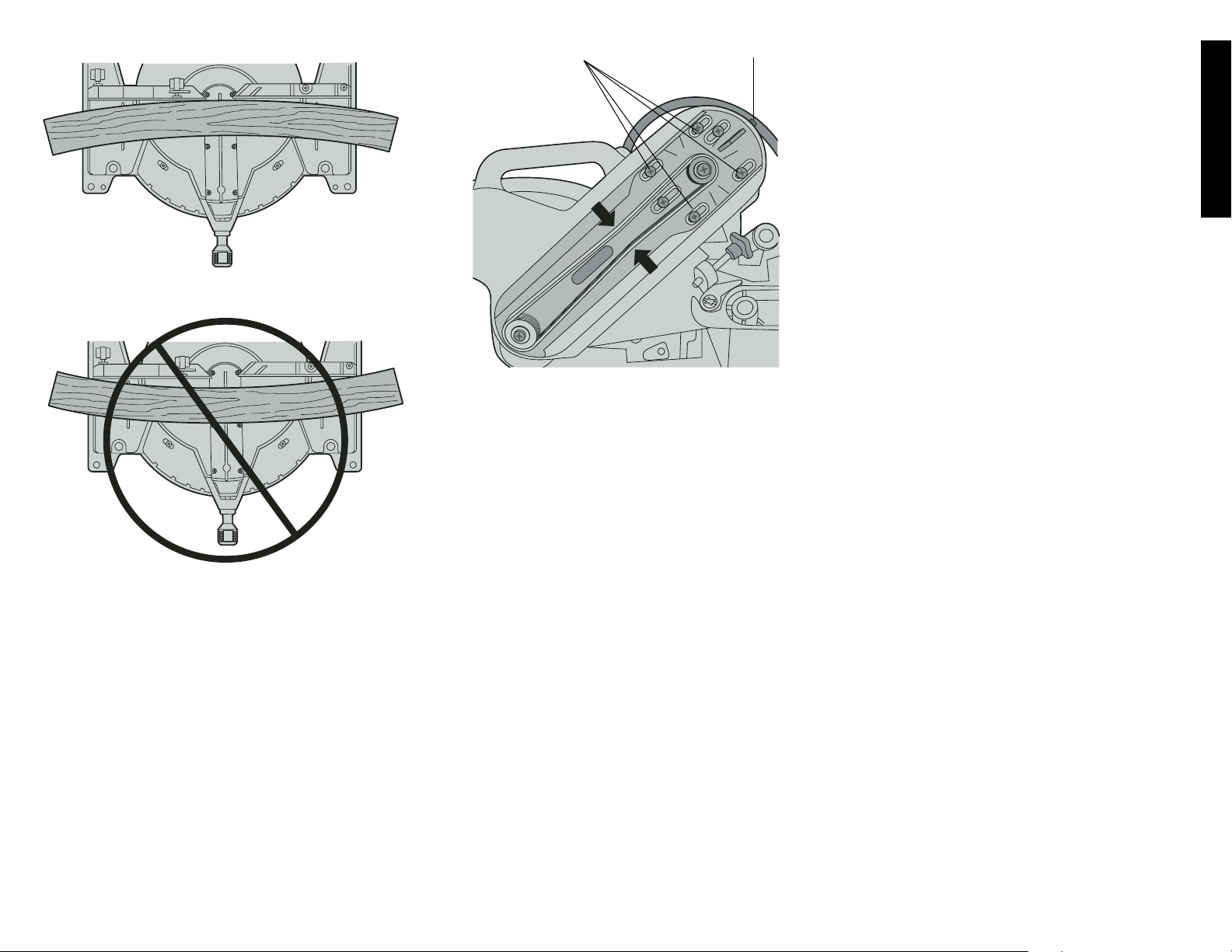
Bowed Material:
When cutting bowed material always position it as shown in
Figure 20 and never like that shown in Figure 21. Positioning
the material incorrectly will cause it to pinch the blade near
the completion of the cut.
Cutting Plastic Pipe or Other Round Material:
Plastic pipe can be easily cut with your saw. It should be cut
just like wood and CLAMPED OR HELD FIRMLY TO THE
FENCE TO KEEP IT FROM ROLLING. This is extremely
important when making angle cuts.
Cutting Large Material:
Occasionally you will encounter a piece of wood a little too
large to fit beneath the blade guard. A little extra height can
be gained by rolling the guard up out of the way. Avoid doing
this as much as possible, but if need be, the saw will operate properly and make the bigger cut. NEVER TIE, TAPE,
OR OTHERWISE HOLD THE GUARD OPEN WHEN
OPERATING THIS SAW.
Removing and Replacing Belt
The belt is designed to last the life of the tool. However,
abuse of the tool could cause the belt to fail.
Page 14
12
English
TABLE 1 COMPOUND MITER CUT (POSITION WOOD WITH BROAD FLAT SIDE ON THE TABLE AND THE NARROW EDGE AGAINST THE FENCE)
SET THIS MITER ANGLE ON SAW
SQUARE BOX
6-SIDED BOX
SET THIS BEVEL ANGLE ON SAW
8-SIDED BOX
10
20
10
10
20
20
30
40
30
40
50
30
50
60
40
50
60
70
60
70
70
80
80
80
Page 15
13
English
If the blade does not turn when the motor is running, the belt
has failed. To inspect or replace the belt, remove the belt
cover screws. Remove the belt cover. Inspect the ribs of the
belt for wear or failure. Check belt tension by squeezing the
belt as shown in Figure 22. The belt halves should almost
touch when squeezing firmly with the thumb and index finger.
To adjust the tension, loosen, but do not remove, the four
Phillips head screws shown. Then rotate the set screw on
the top of the motor plate casting until the proper tension is
achieved. Tighten the four screws securely and replace the
belt cover.
NOTE: Over tightening the belt will cause premature motor
failure.
Maintenance
1. All bearings are sealed. They are lubricated for life and
need no further maintenance.
2. Periodically clean all dust and wood chips from around
AND UNDER the base and the rotary table. Even
though slots are provided to allow debris to pass
through, some dust will accumulate.
3. The brushes are designed to give you several years of
use. If they ever need replacement follow the instructions on page 7 or return the tool to the nearest service
center for repair. Service center locations are packed
with your tool.
Repairs
To assure product SAFETY and RELIABILITY, repairs,
maintenance and adjustment (including brush inspection
and replacement) should be performed by authorized service centers or other qualified service organizations, always
using identical replacement parts.
Three Year Limited Warranty
DEWALT will repair, without charge, any defects due to
faulty materials or workmanship for three years from the
date of purchase. This warranty does not cover part failure
due to normal wear or tool abuse. For further detail of warranty coverage and warranty repair information, visit
www.dewalt.com or call 1-800-4-D
EWALT (1-800-433-
9258). This warranty does not apply to accessories or damage caused where repairs have been made or attempted by
others. This warranty gives you specific legal rights and you
may have other rights which vary in certain states or
provinces.
SET SCREW
SCREWS
FIG. 22
In addition to the warranty, DEWALT tools are covered by
our:
1 YEAR FREE SERVICE
D
EWALT will maintain the tool and replace worn parts
caused by normal use, for free, any time during the first year
after purchase.
90 DAY MONEY BACK GUARANTEE
If you are not completely satisfied with the performance of
your D
EWALT Power Tool, Laser, or Nailer for any reason,
you can return it within 90 days from the date of purchase
with a receipt for a full refund – no questions asked.
RECONDITIONED PRODUCT: Reconditioned product is
covered under the 1 Year Free Service Warranty. The 90
Day Money Back Guarantee and the Three Year Limited
Warranty do not apply to reconditioned product.
FREE WARNING LABEL REPLACEMENT: If your warning
labels become illegible or are missing, call 1-800-4D
EWALT for a free replacement.
FIG. 20
FIG. 21
RIGHT
WRONG
Patent Notification
Manufactured under U.S. patent No. 5,425,294
Other patents may be pending.
Page 16

14
English
Troubleshooting Guide
BE SURE TO FOLLOW SAFETY RULES AND INSTRUCTIONS
TROUBLE! SAW WILL NOT START
WHAT’S WRONG? WHAT TO DO…
1. Saw not plugged in 1. Plug in saw.
2. Fuse blown or circuit breaker tripped 2. Replace fuse or reset circuit breaker
3. Cord damaged 3. Have cord replaced by authorized service center
4. Brushes worn out 4. Have brushes replaced by authorized service center
or replace them yourself as instructed on page 7.
TROUBLE! SAW MAKES UNSATISFACTORY CUTS
WHAT’S WRONG? WHAT TO DO…
1. Dull blade 1. Replace blade. See page 4.
2. Blade mounted backwards 2. Turn blade around. See page 4.
3. Gum or pitch on blade 3. Remove blade and clean with turpentine and coarse
steel wool or household oven cleaner.
4. Incorrect blade for work being done 4. Change the blade type. See page 3.
TROUBLE! BLADE DOES NOT COME UP TO SPEED
WHAT’S WRONG? WHAT TO DO…
1. Extension cord too light or too long 1. Replace with adequate size cord. See page 1.
2. Low house current 2. Contact your electric company
TROUBLE! MACHINE VIBRATES EXCESSIVELY
WHAT’S WRONG? WHAT TO DO…
1. Saw not mounted securely to stand or work bench 1. Tighten all mounting hardware. See page 4.
2. Stand or bench on uneven floor 2. Reposition on flat level surface. See page 6.
3. Damaged saw blade 3. Replace blade. See page 4.
TROUBLE! DOES NOT MAKE ACCURATE MITER CUTS
WHAT’S WRONG? WHAT TO DO…
1. Miter scale not adjusted correctly 1. Check and adjust. See page 6.
2. Blade is not square to fence 2. Check and adjust. See page 6.
3. Blade is not perpendicular to table 3. Check and adjust fence. See page 6.
4. Workpiece moving 4. Clamp workpiece to fence or glue 120 grit sandpaper
to fence with rubber cement.
TROUBLE! MATERIAL PINCHES BLADE
WHAT’S WRONG? WHAT TO DO…
1. Cutting bowed material 1. Position bowed material as shown on page 13.
Page 17

Français
15
Table des matières
DIRECTIVES CONCERNANT LA DOUBLE ISOLATION ET LES
FICHES POLARISÉES ..................................................................................................16
CONSIGNES DE SÉCURITÉ RELATIVES À TOUS LES OUTILS ..............................16
CONSIGNES DE SÉCURITÉ ADDITIONNELLES ........................................................16
RACCORDEMENT ÉLECTRIQUE ................................................................................18
ACCESSOIRES ..............................................................................................................18
RECOMMANDATIONS CONCERNANT LA LAME ......................................................19
DÉBALLAGE DE LA SCIE..............................................................................................19
CARACTÉRISTIQUES TECHNIQUES ..........................................................................19
FAMILIARISATION..........................................................................................................19
MONTAGE SUR UN ÉTABLI..........................................................................................21
INSTALLATION D’UNE LAME........................................................................................21
TRANSPORT DE LA SCIE ............................................................................................21
RÉGLAGES ....................................................................................................................21
RÉGLAGES DE L’ÉCHELLE DE COUPE EN ONGLET..........................................22
RÉGLAGES DE L’INDICATEUR DE L’ONGLET......................................................22
RÉGLAGE DU BISEAU EN ÉQUERRE....................................................................22
BUTÉE DU BISEAU ..................................................................................................22
RÉGLAGE DE LA BUTÉE D’ANGLE DE BISEAU ..................................................22
RÉGLAGE DU GUIDE ..............................................................................................22
FREIN ÉLECTRIQUE AUTOMATIQUE ....................................................................22
VISIBILITÉ ET DÉCLENCHEMENT DU PROTÈGE-LAME ....................................22
BALAIS ............................................................................................................................23
COMMANDES ................................................................................................................23
FONCTIONNEMENT ......................................................................................................24
INTERRUPTEUR ............................................................................................................24
MÉTHODES DE COUPE ................................................................................................24
COUPES TRANSVERSALES ........................................................................................24
COUPES EN BISEAU ....................................................................................................24
QUALITÉ DE LA COUPE................................................................................................24
POSITION DU CORPS ET DES MAINS........................................................................25
FIXATION DE L’OUVRAGE............................................................................................25
SUPPORT DE LONGS OUVRAGES ............................................................................24
COUPE DE CADRES, DE COFFRAGES OU D’AUTRES OUVRAGES
QUADRILATÉRAUX........................................................................................................25
COUPE DE BOISERIES OU D’AUTRES TYPES DE MOULURES..............................25
COUPES EN ONGLET À ANGLES COMBINÉS ..........................................................26
VERNIER ........................................................................................................................26
COUPES DE PLINTHES ................................................................................................26
COUPES DE MOULURES EN COURONNE ................................................................26
TABLEAU 1 ONGLETS MIXTES....................................................................................27
COUPES PARTICULIÈRES............................................................................................29
RETRAIT ET REMPLACEMENT DE LA COURROIE ..................................................29
ENTRETIEN ....................................................................................................................29
GARANTIE ......................................................................................................................29
GUIDE DE DÉPANNAGE ..............................................................................................30
Page 18

Français
16
POUR TOUTE QUESTION OU REMARQUE AU SUJET DE CET OUTIL OU DE TOUT
AUTRE OUTIL D
EWALT, COMPOSER LE NUMÉRO SANS FRAIS :
1 800 4-DEWALT (1 800 433-9258)
Importantes consignes de sécurité
AVERTISSEMENT : lorsqu’on utilise un outil électrique, on doit toujours suiv-
re les consignes de sécurité, y compris celles décrites ci-dessous, afin de
réduire les risques d’incendie, de choc électrique et de blessure.
LIRE TOUTES LES DIRECTIVES
Double isolation
Afin de protéger l’utilisateur contre les chocs électriques, les outils à double isolation sont
complètement recouverts de deux couches distinctes d’isolant électrique ou d’une double
épaisseur de matière isolante. Les outils possédant ce type d’isolation ne sont pas destinés
à être mis à la terre et, par conséquent, sont munis d’une fiche à deux broches permettant
d’utiliser une rallonge ne nécessitant aucune prise de masse.
REMARQUE : le fait que cet outil soit muni d’une double isolation ne signifie pas que l’utilisateur doit cesser de suivre les consignes de sécurité qui s’imposent; l’isolation offre une
protection supplémentaire contre les blessures causées par un choc électrique lorsque les
systèmes d’isolation internes font défaut.
MISE EN GARDE : LORS DE L’ENTRETIEN, N’UTILISER QUE DES PIÈCES DE
RECHANGE IDENTIQUES; faire réparer ou remplacer également les cordons endommagés, y compris les rallonges.
Fiches polarisées
Afin de réduire les risques de choc électrique, cet outil est muni d’une fiche polarisée (c’està-dire que l’une des lames est plus large que l’autre), et ne peut être raccordé qu’à une rallonge polarisée et ce, dans un seul sens. On doit l’inverser si on est incapable de l’enfoncer
complètement. Si la fiche ne s’adapte toujours pas, on doit demander à un électricien qualifié d’installer la prise appropriée. On ne doit jamais modifier la fiche.
Consignes de sécurité relatives à tous les outils
• GARDER LES DISPOSITIFS DE PROTECTION EN PLACE et en bon état de fonction-
nement.
• RETIRER LES CLÉS DE RÉGLAGE; prendre l’habitude de s’assurer que les clés de
réglage soient retirées de l’outil avant de le démarrer.
• GARDER LA ZONE DE TRAVAIL PROPRE; les espaces de travail et les établis encom-
brés sont propices aux accidents.
• UTILISER L’OUTIL DANS DES ENDROITS APPROPRIÉS; ne pas exposer l’outil à la
pluie ou à la neige, ni l’utiliser dans des endroits humides ou mouillés. Garder la zone de
travail bien éclairée.
• TENIR LES ENFANTS À L’ÉCART; s’assurer que personne ne s’approche de la zone
de travail.
• S’ASSURER QUE L’ATELIER SOIT SÛR POUR LES ENFANTS; utiliser des cadenas,
des interrupteurs centraux ou enlever les commandes de démarrage.
• NE PAS FORCER L’OUTIL; pour obtenir de meilleurs résultats et prévenir les risques de
blessure, laisser l’outil couper à la vitesse pour laquelle il a été conçu.
• UTILISER L’OUTIL APPROPRIÉ; ne pas forcer l’outil ou l’accessoire, ni l’utiliser pour
des travaux autres que ceux pour lesquels il a été conçu.
• PORTER DES VÊTEMENTS APPROPRIÉS; ne pas porter de vêtements amples ni de
gants, de cravate, de bague, de bracelet ou d’autres bijoux, car ceux-ci peuvent rester
coincés dans les pièces mobiles. On recommande le port de chaussures antidérapantes.
Couvrir ou attacher les cheveux longs.
• TOUJOURS PORTER DES LUNETTES DE SÉCURITÉ; porter aussi un masque facial ou
un masque anti-poussières lorsqu’on soulève de la poussière. Les lunettes ordinaires protègent uniquement les yeux contre les chocs et ne sont PAS des lunettes de protection.
• IMMOBILISER L’OUVRAGE; retenir l’ouvrage au moyen d’un étau ou de butées fixes s’il
s’avère impossible de le fixer manuellement sur le plateau et contre le guide, ou si les mains
risquent de s’approcher de moins de 15 cm (6 po) de la lame.
• NE PAS TROP ÉTENDRE LES BRAS; les pieds doivent rester ancrés fermement sur le
sol afin de maintenir son équilibre en tout temps.
• BIEN ENTRETENIR L’OUTIL; afin d’obtenir de meilleurs résultats et faire preuve de pru-
dence, garder l’outil propre et bien aiguisé. Suivre les consignes lorsqu’on lubrifie ou qu’on
remplace les accessoires.
• DÉBRANCHER L’OUTIL avant de procéder à l’entretien ou de remplacer des accessoires
comme les lames, les mèches, les organes de coupe, etc.
• RÉDUIRE LES RISQUES DE DÉMARRAGE ACCIDENTEL; s’assurer que l’interrupteur
soit en position d’ARRÊT avant de brancher l’outil.
• UTILISER LES ACCESSOIRES RECOMMANDÉS; consulter le manuel d’utilisation pour
savoir quels accessoires sont appropriés. L’utilisation d’accessoires autres que ceux
recommandés pourrait entraîner des blessures.
• NE JAMAIS METTRE LES PIEDS SUR L’OUTIL; si l’outil se renverse ou est acciden-
tellement mis en marche, il pourrait entraîner des blessures graves.
• VÉRIFIER LES PIÈCES ENDOMMAGÉES; avant de poursuivre les travaux, on doit exam-
iner attentivement les dispositifs de protection, ou toute autre pièce endommagée, afin de
s’assurer qu’il fonctionne toujours adéquatement et qu’il est en mesure d’effectuer les
travaux pour lesquels il a été conçu. Vérifier les pièces mobiles afin de s’assurer qu’elles
soient bien alignées et qu’elles ne restent pas coincées; vérifier également les pièces et les
assemblages afin de s’assurer qu’il n’y ait aucun bris ni aucune autre condition susceptible
de nuire au bon fonctionnement de l’outil. On doit faire réparer ou remplacer toute pièce
endommagée, y compris les dispositifs de protection. Ne pas utiliser l’outil lorsque l’interrupteur marche-arrêt ne fonctionne pas.
• NE JAMAIS LAISSER L’OUTIL FONCTIONNER SANS SURVEILLANCE; COUPER
L’ALIMENTATION et attendre que l’outil s’arrête complètement avant de quitter les lieux.
• NE PAS UTILISER L’OUTIL À PROXIMITÉ DE LIQUIDES, DE GAZ OU DE
POUSSIÈRES INFLAMMABLES; le moteur pourrait créer des étincelles et enflammer les
vapeurs environnantes.
• UTILISER LES RALLONGES APPROPRIÉES; s’assurer que la rallonge électrique soit en
bon état et qu’elle soit en mesure de porter le courant nécessaire à l’outil. Une rallonge de
calibre inférieur entraînera une chute de tension se traduisant par une perte de puissance
et une surchauffe. Le tableau ci-dessous illustre les calibres que l’on doit utiliser selon la
longueur de la rallonge et l’intensité nominale indiquée sur la plaque signalétique. En cas
de doute, utiliser le calibre suivant. Plus le calibre est petit, plus la rallonge peut porter de
courant.
Calibre minimal des cordons de rallonge
Tension Longueur totale du cordon en mètres
120 V De 0 à 7 De 7 à 15 De 15 à 30 De 30 à 45
240 V De 0 à 7 De 7 à 15 De 15 à 39 De 30 à 45
Intensité (A)
Au Au Calibre moyen de fil
moins plus
0-6 18 16 16 14
6 - 10 18 16 14 12
10 - 12 16 16 14 12
12 - 16 14 12 Non recommandé
Consignes de sécurité additionnelles relatives aux
scies à onglets
MISE EN GARDE : AFIN DE RÉDUIRE LES RISQUES DE BLESSURE ET D’ÉVITER
D’ENDOMMAGER SÉRIEUSEMENT L’OUTIL, ON DOIT SUIVRE À LA LETTRE LES CONSIGNES SUIVANTES.
Page 19

Français
17
MISE EN GARDE : Porter un dispositif de protection personnel anti-bruit approprié
durant l’utilisation. Sous certaines conditions et pendant toute la durée de l’utilisation, le
bruit émanant de ce produit pourrait contribuer à la perte d’audition.
AVERTISSEMENT : Certains outils électriques, tels que les sableuses, les scies, les
meules, les perceuses ou certains autres outils de construction, peuvent soulever de la poussière contenant des produits chimiques susceptibles d’entraîner le cancer, des malformations
congénitales ou pouvant être nocifs pour le système reproductif. Parmi ces produits chimiques, on retrouve :
• le plomb dans les peintures à base de plomb,
• la silice cristalline dans les briques et le ciment et autres produits de maçonnerie,
• l’arsenic et le chrome dans le bois de sciage ayant subi un traitement chimique (l’arséniate de cuivre et de chrome).
Le risque associé à de telles expositions peut varier selon la fréquence avec laquelle on
effectue ces travaux. Pour réduire l’exposition à de tels produits, il faut travailler dans un
endroit bien ventilé et utiliser l’équipement de sécurité approprié tel un masque anti-poussières spécialement conçu pour filtrer les particules microscopiques.
• Éviter tout contact prolongé avec la poussière soulevée par cet outil ou autres out-
ils électriques. Porter des vêtements de protection et nettoyer les parties exposées
du corps avec de l’eau savonneuse. S’assurer de bien se protéger afin d’éviter
d’absorber par la bouche, les yeux ou la peau des produits chimiques nocifs.
AVERTISSEMENT : Cet outil peut produire et répandre de la poussière susceptible de
causer des dommages sérieux et permanents au système respiratoire. Toujours utiliser un
appareil respiratoire anti-poussières approprié approuvé par le NIOSH ou l’OSHA. Diriger les
particules dans le sens opposé du visage et du corps.
Pour des fins pratiques et de sécurité, la scie à onglets comprend les étiquettes d’avertissement suivantes.
SUR LE CARTER DU MOTEUR :
AVERTISSEMENT : AFIN DE TRAVAILLER EN TOUTE SÉCURITÉ, LIRE ATTEN-
TIVEMENT LE MANUEL D’UTILISATION AVANT D’UTILISER LA SCIE.
LORS DE L’ENTRETIEN, N’UTILISER QUE DES PIÈCES DE RECHANGE IDEN-
TIQUES.
NE PAS EXPOSER À LA PLUIE NI UTILISER DANS DES ENDROITS HUMIDES.
TOUJOURS PORTER DES LUNETTES DE PROTECTION.
SUR LES GUIDES MOBILES :
TOUJOURS BIEN RÉGLER LE GUIDE
AVANT D’UTILISER LA SCIE. FIXER
SOLIDEMENT LES OUVRAGES DE
PETITES DIMENSIONS AVANT DE
PROCÉDER À LA COUPE.
CONSULTER LE MANUEL.
SUR LE PROTÈGE-LAME : DANGER : SE TENIR LOIN DE LA LAME.
SUR LE PROTÈGE-LAME SUPÉRIEUR : TOUJOURS SERRER
FERMEMENT LA FERRURE AU MOYEN DES DEUX VIS AVANT
D’UTILISER L’OUTIL.
SUR LE PLATEAU (2 ENDROITS) :
TOUJOURS SERRER SOLIDEMENT LES BOUTONS DE RÉGLAGE
AVANT D’UTILISER L’OUTIL. GARDER LES MAINS À AU MOINS 15
CM (6 PO) DU TRAJET DE LA LAME.
NE JAMAIS EFFECTUER DE TRAVAUX À MAINS LEVÉES. NE
JAMAIS CROISER LES BRAS DEVANT LA LAME. RÉFLÉCHIR AFIN
DE PRÉVENIR LES ACCIDENTS.
NE PAS FAIRE FONCTIONNER L’OUTIL SANS SES DISPOSITIFS DE PROTECTION.
• ON DOIT protéger l’alimentation électrique au moyen d’un disjoncteur ou d’un fusible temporisé de 15 ampères ou plus.
• ON DOIT s’assurer que la lame tourne dans le bon sens et que les dents de la partie
inférieure pointent vers l’arrière de la scie à onglets.
• ON DOIT s’assurer que les poignées de serrage soient bien serrées avant de procéder aux
travaux.
• ON DOIT s’assurer que les rondelles de la lame et des brides de serrage soient propres
et que les parties en retrait des colliers soient bien appuyées contre la lame. Bien serrer
la vis de l’arbre.
• ON DOIT maintenir la lame aiguisée.
• ON DOIT s’assurer que les entrées d’air du moteur soient exemptes de copeaux et de
poussière.
• ON DOIT se servir des dispositifs de protection en tout temps, y compris le protège-lame.
• ON DOIT garder les mains éloignées du trajet de la lame.
• ON DOIT couper le courant, débrancher le cordon et attendre que la lame s’arrête complètement avant de procéder à l’entretien ou au réglage de l’outil.
• ON DOIT assurer le support des longs ouvrages en allongeant la surface de travail.
• ON NE DOIT PAS faire fonctionner l’outil sous une tension autre que celle indiquée.
• ON NE DOIT PAS faire fonctionner l’outil si les poignées de serrage ne sont pas bien
serrées.
• ON NE DOIT PAS utiliser de lames dont les dimensions diffèrent de celles recommandées.
• ON NE DOIT PAS placer quoi que ce soit contre le ventilateur de manière à retenir l’arbre
du moteur.
• ON NE DOIT PAS forcer l’outil lors de la coupe. (Afin d’éviter de caler le moteur, même partiellement, et de causer ainsi des dommages importants, on doit laisser ce dernier atteindre
sa vitesse maximale avant de procéder à la coupe.)
• ON NE DOIT PAS couper des métaux ferreux (contenant du fer ou de l’acier) ni de la
maçonnerie.
• ON NE DOIT PAS utiliser de meule, car la chaleur excessive et les particules abrasives
générées par celle-ci peuvent endommager la scie.
• ON NE DOIT PAS permettre à qui que ce soit de se tenir derrière la scie.
• ON NE DOIT PAS lubrifier la lame lorsqu’elle est en marche.
• ON NE DOIT PAS mettre les mains près de la lame lorsque la scie est branchée.
• ON NE DOIT PAS utiliser de lames ayant une vitesse nominale inférieure à 4 800 tr / min.
• ON NE DOIT PAS couper des pièces de petite dimension (on doit toujours pouvoir garder
les mains à au moins 15 cm / 6 po de la lame) sans les fixer.
• ON NE DOIT PAS faire fonctionner l’outil sans ses dispositifs de protection.
• ON NE DOIT PAS utiliser l’outil à main levée.
• ON NE DOIT PAS mettre les mains autour ou derrière la lame.
• ON NE DOIT PAS mettre les mains à moins de 15 cm (6 po) de la lame.
• ON NE DOIT PAS mettre les mains sous la scie lorsque celle-ci est en marche ou branchée,
car la lame y est à découvert.
• ON NE DOIT PAS retirer les mains de la scie ou de l’ouvrage ni lever les bras avant que la
scie ne se soit complètement arrêtée.
• ON NE DOIT PAS utiliser de lubrifiants ni de détergents (particulièrement des produits pulvérisés ou en aérosol) à proximité du dispositif de protection en plastique; fabriqué en polycarbonate, ce dernier risque d’être gravement endommagé par certains produits chimiques.
• ON NE DOIT JAMAIS utiliser l’outil sans la plaque amovible; si cette dernière est endom-
magée, on doit la remplacer, car l’accumulation de copeaux sous la scie peut gêner le fonctionnement de la lame ou rendre l’ouvrage instable durant la coupe.
MISE EN GARDE : ne pas brancher l’outil à la prise électrique avant d’avoir bien lu et com-
pris toutes les directives.
Page 20

18
ARRÊTER L’OUTIL, METTRE LA TÊTE DE LA SCIE VERS LE BAS ET ATTENDRE QUE LA LAME
S’IMMOBILISE COMPLÈTEMENT AVANT DE DÉPLACER LES MAINS OU L’OUVRAGE OU DE
MODIFIER LE RÉGLAGE DE L’OUTIL.
DÉBRANCHER L’OUTIL AVANT DE PROCÉDER À L’ENTRETIEN, DE CHANGER UNE LAME OU
DE DÉPLACER L’OUTIL.
SUR LA BASE
:
Raccordement électrique
S’assurer que l’alimentation corresponde aux valeurs nominales inscrites sur la plaque signalétique de la
scie, soit 120 volts c.a. (courant alternatif seulement), car l’interrupteur fera défaut si on utilise la scie en
courant continu. Une diminution de tension de 10 % ou plus entraînera une chute de puissance et une surchauffe. Tous les outils de D
EWALT sont mis à l’essai en usine. Si cet outil ne fonctionne pas, vérifier l’ali-
mentation électrique.
Accessoires
Les accessoires recommandés pour chaque outil sont vendus séparément aux centres de service
autorisés.
MISE EN GARDE : l’utilisation d’accessoires autres que ceux recommandés, tels que les scies circulaires
doubles à rainer, les organes de coupe à moulures ou les meules abrasives, pourrait présenter un danger.
Pour obtenir plus d’information sur les accessoires, veuillez s’adresser à DEWALT Industrial Tool Co., 701
East Joppa Road, Baltimore, MD 21286, aux États-Unis ou composer le 1 800 433-9258.
Accessoires optionnels
Conçus pour cette scie, les accessoires décrits ci-dessous permettent de faciliter certains travaux, bien que
dans certains cas, d’autres pièces (comme des rallonges de plateau, des butées réglables, des dispositifs
de fixation, etc.) peuvent mieux convenir. On doit prendre soin de bien choisir ses accessoires et de les utiliser correctement.
Rallonge de plateau DW7080
Conçue pour supporter les pièces très longues. La rallonge requiert un assemblage; deux rallonges
peuvent être ajoutées au plateau, soit une de chaque côté.
Butée réglable DW7051
Conçue pour être utilisée avec une rallonge (voir le schéma), la butée permet d’effectuer des coupes
multiples de même longueur (jusqu’à 106,7 cm ou 42,0 po).
Bride de serrage DW7082
Conçue pour fixer solidement l’ouvrage au plateau en vue d’effectuer des coupes de précision (page 4).
Sac à poussière DW7053 (inclus avec certains modèles)
Facile à vider grâce à la glissière, le sac à poussière (non illustré) est conçu pour recevoir presque toute
la sciure produite.
REMARQUE : un déflecteur installé sur le tube chasse-poussière dirige la poussière vers le sol. Si on
le soulève, le tube peut aussi être raccordé à un tube d’aspiration.
Guide pour moulures en couronne DW7084
Permet d’effectuer avec précision la coupe de moulures en couronne (page 4).
LAMES DE LA SCIE : TOUJOURS UTILISER UNE LAME DE 30,5 cm (12 po) À ORIFICE CENTRAL DE
2,54 cm (1 po). LA VITESSE DOIT ÊTRE D’AU MOINS 4 800 tr / min. On ne doit jamais utiliser une lame
de dimension inférieure à celle recommandée puisqu’elle ne procurera pas la protection voulue.
DW7051
BOUTONS
SUPPORT
ORIFICE SUPÉRIOR
(À UTILISER AVEC
LE MODÉLE DW706)
ÉCROUS DE
BLOCAGE
PLAQUE D’EXTRÉMITE
DW7080
Page 21
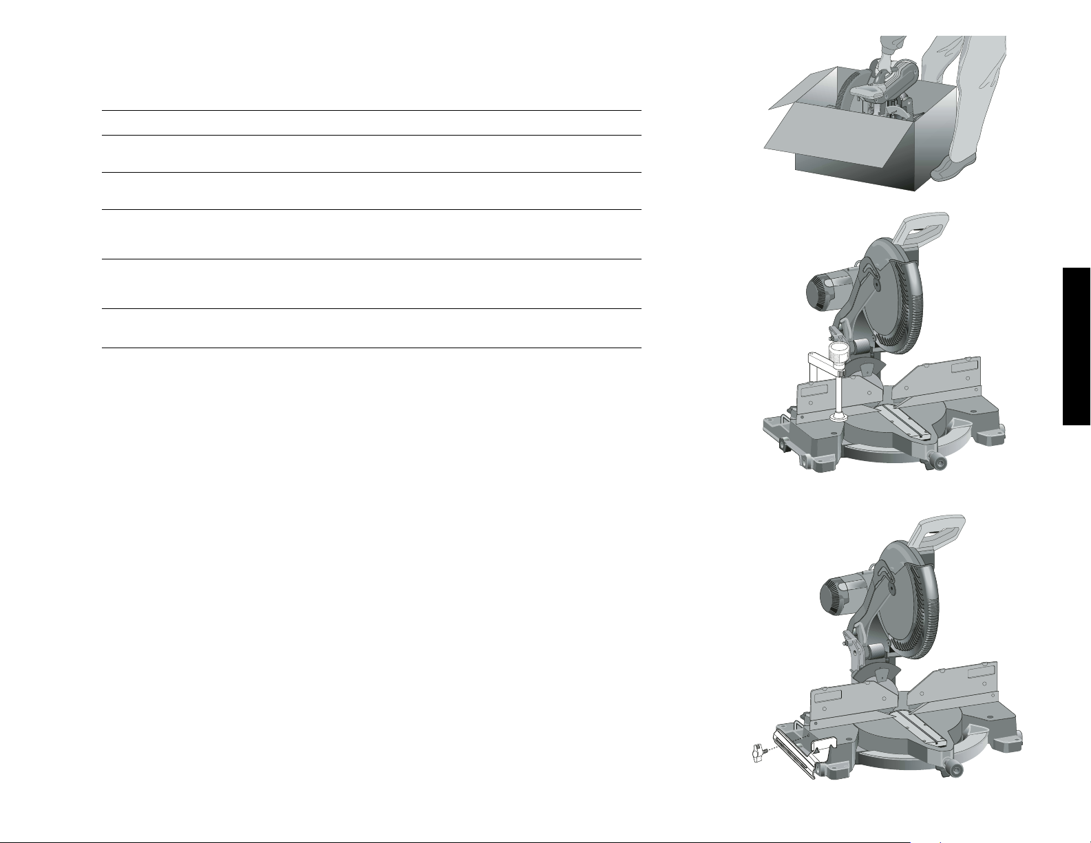
Français
19
GAMMES NOMBRE DESCRIPTION APPLICATIONS TYPES DE COUPE
DE LAMES DE DENTS
DEWALT
Gamme 20 40 Trait mince Usage général Coupes lisses,
Construction Bord jaune (boiseries, terrasses sans éclats
et charpentes)
Gamme 20 60 Trait mince Boiseries fines, Coupes très lisses,
Construction Bord jaune moulures sans éclats
Gamme 40 40 Corps coupé au laser Usage général Coupes lisses,
Menuiserie avec grandes dents (boiseries, terrasses sans éclats
au carbure et charpentes)
Gamme 40 60 Corps coupé au laser Boiseries fines, Coupes très lisses,
Menuiserie avec grandes moulures sans éclats
dents au carbure
Gamme 40 80 Corps coupé au laser Boiseries fines, Coupes ultra lisses,
Menuiserie avec grandes dents moulures et pièces sans éclats
au carbure décoratives en bois
dur ou en contreplaqué
Gamme 40 80 Corps coupé au laser Mélamine, placage Coupes ultra lisses,
Menuiserie avec grandes dents et stratifié sans copeaux ni éclats
au carbure à
géométrie spéciale
Gamme 40 60 Corps coupé au laser Plastique, Corian
MD
Coupes très lisses,
Menuiserie avec dents à et autres matériaux à sans copeaux
géométrie spéciale surface dure
Gamme 40 80 Corps coupé au laser Métaux non ferreux Coupes très lisses,
Menuiserie avec dents à (aluminium, cuivre, sans bavures
géométrie spéciale laiton, etc.)
DW7082
DW7084
Déballage de la scie
Vérifier le contenu de la boîte afin de s’assurer d’avoir bien
reçu toutes les pièces. En plus du manuel d’utilisation, la
boîte devrait contenir :
1. une scie à onglets DW706;
2. une lame D
EWALT de 30,5 (12 po) de diamètre;
3. une clé de réglage de lame rangée dans le logement
illustré à la figure 2;
4. un sac à poussière DW7053 (certains modèles).
Caractéristiques techniques
CAPACITÉ DE COUPE
Onglet de 50° à gauche et à droite
Biseau de 48° à gauche et à droite
Onglet de 0°
Hauteur max. de 8,9 cm Largeur obtenue : 18,8cm
Largeur max. de 20,1 cm Hauteur obtenue : 7,4 cm
Onglet de 45°
Hauteur max. de 8,9 cm Largeur obtenue : 13,5 cm
Largeur max. de 14,2 cm Hauteur obtenue : 7,4 cm
Biseau de 45° à gauche
Hauteur max. de 5,8 cm Largeur obtenue : 18,8 cm
Largeur max. de 20,1 cm Hauteur obtenue : 4,8 cm
FIG. 1
Biseau de 45° à droite
Largeur max. de 20,1 cm Hauteur obtenue : 3,1 cm
Hauteur max. de 4,1 cm Largeur max. de 18,8 cm
On peut régler la scie à un angle 45° à gauche ou à droite
pour couper des plinthes ayant une épaisseur de 2,3 cm
(0,9 po) et une hauteur de 15,2 cm (6,0 po).
MÉCANISME D’ENTRAÎNEMENT
Moteur de 120 volts
Moteur 15 A, 2 200 W
Coupes à 4 000 tr / min Engrenages
hélicoïdaux avec
Courroie Multi-V roulements à
rouleaux
Lame au carbure Frein électrique automatique
Familiarisation
La scie à onglets est complètement assemblée au moment
de sa livraison.
Ouvrir la boîte et retirer la scie en la soulevant au moyen de
la poignée pratique prévue à cette fin, tel qu’illustré à la figure 1.
Déposer la scie sur une surface unie et plane, comme un
établi ou une table solide.
Étudier les deux figures à la page 20 pour se familiariser
avec la scie et ses composantes. La section suivante sur les
Page 22

Français
20
FIG. 2
DISPOSITIF DE
PROTECTION
GUIDE
DROIT
BOUTON DE
SERRAGE DE
L’ONGLET
DISPOSITIF DE
VERROUILLAGE
DE L’ONGLET
ÉCHELLE DE
COUPE EN
ONGLET
ORIFICES DE
MONTAGE SUR
L’ÉTABLI
BOUTON DE SER-
RAGE DU GUIDE
GAUCHE
GOUPILLE DE
VERROUILLAGE
POIGNÉE DE
MANŒUVRE
ÉCHELLE DE
COUPE EN
BISEAU
FIG. 4
INTERRUPTEUR À
GÂCHETTE
POIGNÉE DE
MANŒUVRE
GUIDE
GAUCHE
CARTER DU
MOTEUR
LEVIERS DE
SURPASSEMENT
DE LA BUTÉE
D’ANGLE DE
BISEAU DE 45º
TUBE CHASSE-
POUSSIÈRE
CAPUCHON
D’INSPECTION
DES MOTEUR
BOUTON DE
SURPASSEMENT DE LA
BUTÉE
D’ANGLE DE
BISEAU DE 0º
GOUPILLE DE
VERROUILLAGE
BUTÉE D’ANGLE DE
33,85º– CLIQUETS
POIGNÉE DE
TRANSPORT
CLÉ DE
RÉGLAGE DE
LAME
VIS DE RÉGLAGE
DE LA BUTÉE
D’ANGLE DE
BISEAU DE 45º
BOUTON DE
VERROUILLAGE
D’ANGLE DE
BISEAU
BASE
INDENTÉE
VIS DE RÉGLAGE DE
LA BUTÉE D’ANGLE
DE BISEAU DE 0º
-DÉTAILLÉE 1-
-DÉTAILLÉE 2-
C
FIG. 3
E
F
G
I
H
A
B
D
Page 23

Français
21
FIG. 7
FIG. 6
ÉCHELLE DE
COUPE EN
ONGLETS
INDICATEUR
J
K
T
FIG. 5
FIG. 8
3. Desserrez la vis du support du pare-main (B) sans
l’enlever de manière à ce que le support puisse être
levé suffisamment haut pour accéder à la vis de la lame.
4. Enfoncez le bouton de verrouillage de la broche (C) tout
en tournant la lame de scie manuellement de manière à
engager le dispositif de verrouillage.
5. Maintenez le bouton enfoncé et utilisez l’autre main et la
clé fournie (D) pour desserrer la vis de la lame. (Tournez
dans le sens horaire, filets inversés)
6. Enlevez la vis (E) de la lame, la rondelle de bride de fixation extérieure (F) et la lame (G). L’adaptateur de lame
de 25.4 mm (1 po) (H), si utilisé, et la rondelle de bride
de fixation intérieure (I) peuvent être laissés sur la
broche.
REMARQUE : L’adaptateur de lame de 25.4 mm (1 po)
n’est pas utilisé pour les lames dotées d’un trou de lame
de 15.88 mm(5/8 po).
Pose d’une lame
1. Débranchez la scie.
2. Le bras étant levé, le pare-main inférieur ouvert et le
porte-pivot levé, posez la lame sur la broche, sur l'adaptateur de lame [si une lame à trou de 25.4 mm (1 po)
est utilisée] et contre la rondelle de bride de fixation
intérieure, les dents se trouvant au bas de la lame et
pointant vers l'arrière de la scie.
3. Assemblez la rondelle de bride de fixation extérieure sur
la broche.
4. Posez la vis de la lame et, tout en engageant le bouton
de verrouillage de la broche, serrez fermement la vis
avec la clé fournie. (Tournez dans le sens antihoraire,
filets inversés)
REMARQUE : L’adaptateur de lame n’est pas utilisé pour
les lames à trou de 15.88 mm (5/8 po) et doit être rangé
dans un endroit sûr pour un usage ultérieur.
5. Remettez le support de pare-main à sa position d’origine, puis serrez fermement la vis du support de paremain afin de maintenir en place le support.
AVERTISSEMENT :
• Le support du pare-main doit être remis
à sa position d’origine et la vis doit être
serrée avant d'activer la scie.
• Si vous négligez de le faire, le paremain risque d'entrer en contact avec la
lame de scie tournante et ainsi causer
des dommages à la scie et des
blessures corporelles graves.
Transport de la scie à onglets
METTRE LA SCIE HORS TENSION ET LA
DÉBRANCHER AVANT DE LA TRANSPORTER OU
D’EFFECTUER QUELQUE RÉGLAGE QUE CE SOIT.
Afin de pouvoir transporter aisément la scie à onglets d’un
endroit à l’autre, celle-ci est munie d’une base indentée et
d’une poignée se trouvant sur la partie supérieure du bras
(figure 4).
Réglages
DÉBRANCHER LA SCIE À ONGLETS AVANT DE
PROCÉDER AUX RÉGLAGES.
VIS DE
RÉGLAGE DE
L’INDICATEUR
L
M
réglages fait référence à ces termes; on doit donc connaître
les pièces et leur emplacement.
Appuyer légèrement sur la poignée de manoeuvre et tirer
sur la goupille de verrouillage vers le bas (figure 2).
Relâcher doucement la pression ainsi exercée et retenir le
bras afin qu’il puisse monter jusqu’à sa position maximale.
Se servir de la goupille de verrouillage lorsqu’on déplace la
scie, et transporter cette dernière au moyen de la poignée
de transport ou de la base indentée prévue à cet effet, tel
qu’illustré à la figure 2.
Montage sur un établi
Les quatre pattes de la scie sont pourvues d’orifices afin de
faciliter le montage sur l’établi, tel qu’illustré à la figure 2.
(Deux orifices de dimensions différentes sont fournis afin de
pouvoir recevoir des vis de divers calibres; il n’est pas
nécessaire d’utiliser les deux orifices. )
Toujours fixer la scie solidement sur une surface stable afin
d’empêcher tout mouvement. Pour que l’outil soit plus facile
à transporter, on peut le monter sur une planche de contreplaqué d’au moins 1,27 cm (1/2 po) d’épaisseur, qu’on peut
ensuite fixer sur la rallonge ou transporter de site en site et
fixer de nouveau.
REMARQUE : si on installe la scie sur une planche de contreplaqué, on doit s’assurer que les vis de montage ne
dépassent pas la planche; cette dernière doit en effet être de
niveau avec la surface du plateau. Lorsqu’on fixe la scie à une
surface de travail, on ne doit serrer les étaux que sur les protubérances prévues à cette fin, près des orifices de montage.
Le fait de serrer les étaux à n’importe quel autre endroit pourrait nuire au bon fonctionnement de la scie.
MISE EN GARDE : afin d’assurer que la scie ne se coince
pas et qu’elle coupe avec précision, on doit l’installer sur une
surface unie et plane. Si la scie tend à basculer, mettre une
cale mince sous l’une des pattes pour la stabiliser.
DIRECTIVES DE SÉCURITÉ
IMPORTANTES
Changement ou pose d’une
nouvelle lame de scie (Fig. 3)
MISE EN GARDE :
• N’enfoncez jamais le bouton de verrouillage de la broche
lorsque la lame est sous tension ou qu’elle continue de
tourner après l’arrêt de la scie.
• Ne coupez pas du métal ferreux (contenant du fer ou de
l’acier), de la maçonnerie ou du fibrociment avec cette
scie à onglets.
Dépose de la lame
1. Débranchez la scie.
2. Levez le bras à la position supérieure, puis lever le paremain (A) aussi haut que possible.
Page 24

Français
22
FIG. 9
RÉGLAGE DE LA BUTÉE D’ANGLE DE BISEAU À 45º
VERS LA GAUCHE OU VERS LA DROITE (FIG. 9)
REMARQUE : s’assurer que l’angle de biseau soit à 0º et
que l’indicateur soit réglé avant d’ajuster les angles de
biseau à 45º. S’assurer que les leviers de surpassement de
la butée d’angle de biseau de 45º soient poussés vers
l’intérieur pour obtenir un réglage précis.
Pour régler la butée à un angle de 45º vers la droite, desserrer la poignée et tirer sur le bouton de surpassement de la
butée (fig. 2) pour passer par-dessus la butée de 0º. Si la
scie est complètement à droite et l’indicateur ne pointe pas
exactement la marque de 45º, tourner la vis de la butée (O)
droite jusqu’à ce que cela se produise.
Pour régler la butée à 45º á gauche, desserrer d’abord la
poignée de verrouillage et incliner la tête vers la gauche. Si
l’indicateur ne pointe pas directement la marque de 45º.,
tourner la vis de la butée jusqu’à ce que cela se produise.
RÉGLAGE DE LA BUTÉE D’ANGLE DE BISEAU À 33,85º
(FIG. 9)
REMARQUE : s’assurer que l’angle de biseau soit à 0º et
que l’indicateur soit réglé avant d’ajuster les angles de
biseau à 33,85º. Pour ce faire, escamoter les cliquets de la
butée (P), desserrer la poignée de verrouillage d’angle de
biseau (Q) et incliner la tête vers la gauche. Si l’indicateur ne
pointe pas directement la marque de 33,85º, on doit tourner
la vis en contact avec le cliquet jusqu’à ce que cela se produise. Pour régler la butée à un angle de 33,85º à droite,
escamoter les cliquets de la butée. Desserrer la poignée et
tirer sur le bouton de surpassement de la butée pour passer par-dessus la butée de 0º. Si la scie est complètement à
droite et l’indicateur ne pointe pas exactement la marque de
33,85º, tourner la vis de la butée droite jusqu’à ce que cela
se produise.
RÉGLAGE DU GUIDE
Arrêter et débrancher la scie à onglets
Afin que la scie puisse réaliser un biseau complet de 48° à
gauche ou à droite, les guides peuvent être réglés de
manière à obtenir le jeu nécessaire. Pour régler le guide,
desserrer le bouton en plastique illustrés à la figure 9 (R ), et
faire glisser le guide vers l’extérieur. Faire un essai à vide la
scie arrêtée et vérifier s’il y a suffisamment de jeu. Régler le
guide de manière à le placer plus près possible de la lame
afin d’assurer un support maximal à l’ouvrage sans gêner les
mouvements verticaux du bras; bien serrer le bouton. Une
fois la coupe en biseau terminée, on ne doit pas oublier de
replacer le guide à droite.
REMARQUE : la rainure des guides peut devenir obstruée
par la sciure de bois. Si tel est le cas, la dégager au moyen
d’un bâtonnet ou d’un jet d’air à basse pression.
FREIN ÉLECTRIQUE AUTOMATIQUE
La scie est munie d’un frein électrique non réglable destiné
à arrêter automatiquement la lame dans un délai de cinq
secondes suivant le relâchement de la gâchette. Le frein
peut, à l’occasion, prendre plus de temps à s’engager ou,
plus rarement, ne pas s’engager du tout, dans lequel cas, la
lame continue de tourner lentement et s’arrête graduellement.
Si cela se produit, ou si la scie saute, démarrer et arrêter
celle-ci quatre ou cinq fois. Si le problème persiste, retourner la scie à un centre de service D
EWALT en vue de régler
le problème.
On doit toujours s’assurer que la lame se soit complètement
arrêtée avant de la retirer de la plaque amovible. Le frein
n’étant pas un dispositif de sécurité, on doit assurer sa propre protection en restant toujours vigilant.
VISIBILITÉ ET DÉCLENCHEMENT DU PROTÈGE-LAME
Le protège-lame se lève ou se baisse automatiquement
lorsqu’on abaisse ou qu’on soulève le bras respectivement.
On peut lever le protège-lame manuellement lorsqu’on
installe ou qu’on retire les lames ou qu’on inspecte la scie.
NE JAMAIS LEVER LE PROTÈGE-LAME MANUELLEMENT LORSQUE LA SCIE EST EN MARCHE.
La section avant du protège-lame est dotée de fentes qui
améliorent la visibilité durant la coupe. Bien que, grâce à
ces fentes, les projections de débris soient considérable-
Q
S
R
R
P
E
O
REMARQUE : la scie à onglets a fait l’objet d’un réglage
complet et précis à l’usine au moment de sa fabrication. Si
des réglages supplémentaires s’avèrent nécessaires à la
suite de la manutention et de l’expédition de l’outil, ou pour
toute autre raison, on doit procéder en suivant les étapes
décrites ci-dessous.
Une fois effectués, les réglages doivent rester précis.
Il est donc important de prendre le temps de bien suivre les
directives indiquées ci-dessous afin d’assurer la précision
de coupe dont la scie est apte à procurer.
RÉGLAGE DE L’ÉCHELLE DE COUPE EN ONGLET
(FIG. 5)
Placer une équerre contre le guide et la lame, tel qu’illustré.
(Éviter tout contact entre l’extrémité des dents de la lame et
l’équerre afin de ne pas fausser les mesures.)
Desserrer le bouton de serrage et faire basculer le bras
jusqu’à ce que le dispositif de verrouillage bloque le bras à
la position zéro; ne pas serrer le bouton de serrage. Si la
lame n’est pas exactement perpendiculaire au guide,
desserrer les trois vis qui retiennent l’échelle à la base, et
déplacer l’échelle vers la gauche ou vers la droite, jusqu’à
ce que la lame soit complètement perpendiculaire au guide,
tel qu’indiqué par l’équerre; resserrer les trois vis. Ne pas
tenir compte de l’information affichée sur l’indicateur pour le
moment.
RÉGLAGE DE L’INDICATEUR DE L’ONGLET (FIG. 6, 7)
Desserrer le bouton de serrage (J), tel qu’illustré à la figure
7, en tournant vers la gauche et placer le bras à la position
zéro en appuyant sur le dispositif de verrouillage (K).
Maintenir le bouton desserré et laisser le dispositif de verrouillage s’enclencher à la position voulue tout en tournant le
bras au-delà de la position zéro. Observer l’indicateur et
l’échelle par le regard (figure 6). Si l’indicateur n’affiche pas
exactement zéro, desserrer la vis le retenant et aligner l’indicateur à nouveau; resserrer la vis.
RÉGLAGE DU BISEAU EN ÉQUERRE (FIG. 8)
Pour aligner la lame perpendiculairement au plateau rotatif,
verrouiller le bras en position inférieure. Mettre une équerre
contre la lame en prenant soin de ne pas l’accrocher dans
les dents.
Relâcher le bouton de serrage en s’assurant que le bras
soit fermement appuyé contre la butée du biseau de 0º.
Déplacer la vis de réglage de ce dernier jusqu’à ce que la
lame ne présente plus d’angle de biseau par rapport au
plateau (à 0º).
INDICATEUR DU BISEAU (FIG. 8)
Si l’indicateur du biseau (M) n’affiche pas zéro, desserrer la
vis et effectuer le réglage requis, le cas échéant. Ne pas
retirer la plaque d’acier située à l’avant de l’indicateur, car
celle-ci empêche la résine du bois de s’accumuler sur
l’échelle du biseau durant son utilisation.
N
Page 25

Français
23
MÉTHODE DE COUPE INCORRECTE
MÉTHODE DE COUPE INCORRECTE
MÉTHODE DE COUPE CORRECTE
FIG. 10
MÉTHODE DE COUPE CORRECTE
FIG. 10A
FIG. 10B
FIG. 10C
ment réduites, il reste qu’elles constituent des ouvertures;
on doit toujours porter des lunettes de protection lorsqu’on
s’en sert pour voir son ouvrage.
Balais
DÉBRANCHER LA FICHE DE LA PRISE ÉLECTRIQUE
On doit inspecter régulièrement les balais de charbon. Pour
ce faire, débrancher l’outil, retirer le capuchon d’inspection
des moteur (figure 2), puis soulever le ressort des balais et
retirer les balais. Maintenir ces derniers propres afin qu’ils
puissent glisser librement dans leurs guides. Lorsqu’on
place un balai, on doit prendre soin de le mettre dans le
même sens qu’avant. Divers symboles apparaissent sur les
côtés de chaque balai. Lorsque l’usure dépasse environ 1,0
cm (1/2 po), le ressort n’exerce plus aucune pression; on
doit alors remplacer les balais.
Afin d’assurer le bon fonctionnement du frein électrique,
n’utiliser que les balais D
EWALT identiques et de même
qualité offerts aux centres de service de la compagnie.
Laisser l’outil marcher à vide pendant 10 minutes avant de
l’utiliser afin de s’assurer que les nouveaux balais soient bien
en place. Le frein électrique peut fonctionner de manière
erratique pendant cette période, mais fonctionnera de nouveau normalement une fois les balais bien rodés et en place.
On doit toujours replacer le capuchon après avoir effectué
l’inspection ou l’entretien des balais.
Durant le rodage des balais, NE PAS RETENIR L’INTERRUPTEUR À GÂCHETTE AU MOYEN D’UNE CORDE,
D’UN RUBAN ADHÉSIF OU D’AUTRE MOYEN DE
BLOCAGE; NE LE MAINTENIR EN POSITION QU’AVEC
LES MAINS.
Commandes
La scie à onglets comprend plusieurs commandes principales décrites brièvement aux présentes. Pour obtenir plus
d’information sur ces commandes, il suffit de consulter les
sections ci-dessous.
COMMANDE D’ONGLET (FIG. 7)
Le levier et la gâchette de verrouillage et de réglage de
l’onglet permet d’effectuer des coupes à 50º vers la gauche
et la droite. Pour ce faire, desserrer la poignée de verrouillage (J) en la tournant vers la gauche, appuyer sur la
gâchette (K) et régler la scie à l’angle voulu en se servant
de l’échelle de réglage; resserrer la poignée en la tournant
vers la droite.
INTERRUPTEUR À GÂCHETTE
L’interrupteur à gâchette (fig. 2) permet de démarrer et
d’arrêter l’outil. La gâchette est munie d’un orifice dans
lequel on peut insérer un cadenas et ainsi bloquer la scie en
position d’arrêt.
POIGNÉE DE VERROUILLAGE D’ANGLE DE BISEAU
(FIG. 9)
La poignée de verrouillage d’angle (Q) permet d’effectuer
des coupes en biseau à 48º vers la gauche ou la droite.
Pour desserrer la poignée et régler l’angle de biseau, tourn-
Page 26

Français
24
er cette dernière vers la gauche. La tête de scie s’incline
aisément une fois qu’on a tiré sur le bouton de surpassement de la butée d’angle de 0º (S). Pour resserrer la
poignée, la tourner vers la droite. Les marques indiquant les
angles de biseau sont situées sur la partie avant inférieure
du bras de la scie (Fig. 7, T).
BOUTON DE SURPASSEMENT DE LA BUTÉE
D’ANGLE DE BISEAU DE 0º (FIG. 9)
Le bouton de surpassement de la butée d’angle de 0º (B)
permet d’effectuer des coupes en biseau vers la droite audelà de cette marque.
La scie s’arrête automatiquement à zéro lorsqu’on la
soulève vers la gauche. Pour dépasser la marque de 0º
vers la droite, tirer sur le bouton de surpassement; on peut
verrouiller ce dernier en le faisant tourner d’un demi-tour
quand il est soulevé.
BOUTON DE SURPASSEMENT DE LA BUTÉE
D’ANGLE DE BISEAU DE 45º (FIG. 9)
Ces boutons de surpassement sont fixés solidement au
moyen d’une vis afin d’empêcher tout mouvement imprévu.
Utilisant la mèche appropriée, desserrer la vis au moyen de
la clé de réglage de la lame afin de pouvoir déplacer les glissières vers l’extérieur et de faire pivoter la tête de scie audelà de la marque de 45º; s’assurer de bien resserrer la vis
une fois le réglage terminé.
BUTÉES D’ANGLE DE BISEAU DE 33,85º (FIG 9)
Ces deux cliquets (P) servent à bloquer la tête de scie à un
angle de biseau de 33,85º. On utilise surtout ce réglage
pour couper des moulures en couronne déposées à plat sur
une surface.
VERROUILLAGE DE LA TÊTE VERS LE BAS (FIG. 9)
Pour verrouiller la tête de scie vers le bas, on doit la pencher
vers en bas, pousser la goupille (U), puis relâcher la tête. La
scie ainsi bloquée en position, on peut la déplacer sans danger d’un endroit à l’autre. Pour dégager la tête, il suffit de la
pencher de nouveau vers le bas et de retirer la goupille.
Fonctionnement
Brancher la scie dans une prise de courant résidentielle de
60 Hz; consulter la plaque signalétique afin de connaître la
tension nominale de l’outil. S’assurer que le cordon ne gêne
pas les travaux.
INTERRUPTEUR
Pour démarrer la scie, appuyer sur l’interrupteur à gâchette;
le relâcher pour arrêter l’outil. Attendre que la scie atteigne
sa vitesse maximale avant de procéder à la coupe, puis
relâcher l’interrupteur et attendre que le frein arrête complètement la lame avant de soulever la tête de scie. Bien
que la scie ne soit pas munie d’un dispositif de verrouillage
en position de marche, la gâchette est munie d’un orifice
dans lequel on peut insérer un cadenas et ainsi bloquer la
scie en position d’arrêt.
MÉTHODE DE COUPE
REMARQUE : malgré le fait que la scie soit conçue pour
couper plusieurs types de matériaux non ferreux, le présent
manuel décrit uniquement la méthode de coupe du bois,
laquelle s’applique également aux autres types de matériaux. NE PAS UTILISER LA SCIE À ONGLETS POUR
COUPER DES MÉTAUX FERREUX (CONTENANT DU
FER OU DE L’ACIER) NI DE LA MAÇONNERIE. Ne pas
utiliser de lames abrasives.
COUPES TRANSVERSALES
Bien que la coupe de pièces multiples ne soit pas recommandée, on peut toutefois en effectuer de façon sécuritaire
si on s’assure d’abord de bien retenir chacune des pièces
sur le plateau et contre le guide. On effectue une coupe
transversale en coupant à travers les fibres du bois et ce, à
n’importe quel angle. Pour réaliser une coupe transversale
droite, on doit régler le bras à la position zéro et tenir le bois
sur le plateau en l’appuyant fermement contre le guide.
Démarrer la scie en appuyant sur l’interrupteur à gâchette.
Après environ une seconde, lorsque la scie a atteint sa
vitesse maximale, abaisser graduellement et lentement le
bras pour couper à travers le bois; attendre que la lame
s’arrête complètement avant de relever le bras. Pour obtenir
une coupe transversale en onglet, régler le bras dans une
position autre que zéro. Bien que toute position entre 0° et
50° à gauche ou à droite convienne, l’angle le plus souvent
utilisé pour scier un coin en travers est de 45°. Une fois
l’angle sélectionné, s’assurer d’avoir bien serré le bouton de
serrage, puis effectuer la coupe suivant les directives
décrites ci-dessus.
COUPES EN BISEAU
Une taille en biseau est une coupe transversale réalisée
lorsque la lame forme un angle de biseau avec le bois. Afin
de régler cet angle, desserrer le bouton de serrage et
déplacer la scie vers la gauche jusqu’à la position voulue.
(Pour ce faire, on doit déplacer le guide afin d’obtenir le jeu
nécessaire.) Une fois l’angle obtenu, bien serrer le bouton.
On peut régler l’angle de biseau entre 48° à droite et 48° à
gauche, et le bras entre la position 0° et 50° à droite ou à
gauche. Lorsqu’on coupe à des angles importants, il pourrait s’avérer nécessaire de retirer les guides droit ou
gauche. Pour ce faire, tourner plusieurs fois les boutons
appropriés et laisser glisser les guides hors de leur support.
QUALITÉ DE LA COUPE
L’uniformité d’une coupe dépend de plusieurs variables : le
type d’ouvrage, le type et l’état des lames et la vitesse de
coupe sont tous des facteurs déterminants pour la qualité
d’une coupe.
Lorsqu’on effectue des coupes de précision, telles que sur
des moulures, et qu’on veut obtenir des arêtes aussi lisses
que possible, il faut choisir une lame bien affûtée (dents de
carbure de 60) et une vitesse plus lente et uniforme.
Fixer solidement l’ouvrage afin de s’assurer qu’il ne glisse
pas durant la coupe. Toujours attendre que la lame s’arrête
FIG. 11
FIG. 12
FIG. 13
A.
B.
ANGLE “A”
FIG. 14
ÉCHELLE DE
COUPE EN
ONGLETS
FIG. 15
Page 27

Français
25
FIG. V1
FIG. V2
BRAS
D’ONGLET
ALIGNER LA MARQUE CENTRALE DU VERNIER AVEC LA
VALEUR ENTIÈRE INSCRITE SUR L’ÉCHELLE
(À 24 DEGRÉS À DROITE)
ALIGNER LA MARQUE DU VERNIER DE UN QUART DE
DEGRÉ AVEC LA VALEUR ENTIÈRE LA PLUS PRÈS
INSCRITE SUR L’ÉCHELLE
(RÉGLAGE DE L’ONGLET À 24 1/4˚ DE DEGRÉS À DROITE).
PLAQUE
AMOVIBLE
FIG. 16
complètement avant de relever le bras. Si la coupe n’élimine pas les petites fibres de bois sur la partie arrière de
l’ouvrage, couvrir la section au moyen d’un morceau de
ruban-cache, scier à travers le ruban et le retirer soigneusement une fois la coupe terminée.
Avant d’effectuer divers types de coupe, consulter la liste
des lames recommandées à la page 19 afin de sélectionner
celles qui conviennent le mieux aux coupes requises.
POSITION DU CORPS ET DES MAINS (FIGURE 10)
Pour obtenir facilement et en toute sécurité une coupe précise, le corps et les mains doivent être placés correctement.
Ne jamais mettre les mains à proximité de la zone de coupe;
les écarter d’au moins 15 cm (6 po) de la lame. Durant la
coupe, maintenir solidement l’ouvrage sur le plateau et contre le guide. Garder les mains dans cette position jusqu’au
relâchement de la gâchette et l’arrêt complet de la lame.
TOUJOURS EFFECTUER UN ESSAI À VIDE (OUTIL
DÉBRANCHÉ) AVANT DE RÉALISER LES COUPES DE
FINITION AFIN DE VÉRIFIER LE TRAJET DE LA LAME.
NE PAS CROISER LES BRAS (FIGURE 10A).
Les pieds doivent rester ancrés fermement sur le sol afin de
maintenir son équilibre en tout temps. Suivre le trajet latéral
du bras en se tenant légèrement à côté de la lame. Suivre
la marque effectuée au crayon à mine en regardant à
travers les fentes prévues à cet effet.
FIXATION DE L’OUVRAGE
Arrêter et débrancher la scie
S’il s’avère impossible d’immobiliser l’ouvrage sur le
plateau ou contre le guide avec les mains (forme
irrégulière, etc.) ou de maintenir les mains à plus de 15 cm
/ 6 po de la lame, on doit utiliser une bride de serrage ou
une ferrure quelconque.
Pour obtenir de meilleurs résultats, utiliser la butée fixe
DW7082 recommandée pour cette scie, vendue séparément chez les dépositaires locaux ou les centres de service autorisés D
EWALT.
D’autres dispositifs de fixation tels qu’une bride à ressort,
un serre-joint à barre ou un serre-joint en C, peuvent convenir pour certains ouvrages, selon la dimension et la
forme. On doit choisir et positionner ces dispositifs avec
soin et effectuer un essai à vide avant de réaliser la coupe.
Le fait que le guide gauche ou droit puisse glisser d’un
côté et de l’autre facilite la fixation des pièces.
SUPPORT DE LONGS OUVRAGES
Arrêter et débrancher la scie
TOUJOURS ASSURER LE SUPPORT DES LONGS
OUVRAGES
Pour obtenir de meilleurs résultats, utiliser une rallonge
DW7080 conçue pour élargir le plateau de la scie; celle-ci
est vendue séparément chez les dépositaires locaux.
Supporter les longs ouvrages au moyen d’un banc de sciage ou de tout autre dispositif pratique afin d’empêcher les
extrémités de tomber.
COUPE DE CADRES, DE COFFRAGES OU D’AUTRES
OUVRAGES QUADRILATÉRAUX
Pour mieux comprendre comment fabriquer les ouvrages
énumérés aux présentes, on suggère de réaliser quelques
projets plus simples utilisant des retailles jusqu’à ce qu’on
se sente bien à l’AISE avec la scie, qui constitue l’outil parfait pour tailler des coins en onglet comme ceux illustrés à la
figure 12. Pour effectuer le joint illustré au croquis A de la figure 11, on doit placer le bras à 45° de manière à tailler un
coin en onglet sur les deux planches et à produire ainsi un
coin droit. Le bouton de réglage du biseau doit être bloqué
à 45º et le bras, à la position zéro. La surface plane et large
de la planche doit être appuyée contre le plateau et le côté
étroit, contre le guide. On peut aussi effectuer une coupe en
onglet vers la gauche et la droite en appuyant la surface
large contre le guide.
COUPE DE BOISERIES OU D’AUTRES TYPES DE
MOULURES
Le joint illustré au croquis B de la figure 11 a été effectué en
taillant deux planches en onglet pour produire un coin droit.
Le bouton de réglage du biseau doit être bloqué à la position zéro et le bras, à 45°.
Comme dans le cas précédent, la surface plane et large de
la planche doit être contre le plateau et le côté étroit, contre
le guide. Les techniques illustrées aux croquis A et B de la
figure 11 ne s’appliquent qu’aux ouvrages quadrilatéraux.
Les angles d’onglet et de biseau varient selon le nombre de
côtés; le diagramme ci-dessous indique quel angle convient
à quel ouvrage.
(Le diagramme ne vise que les objets à côtés égaux.) On
peut obtenir l’angle d’onglet ou de biseau des autres
ouvrages en divisant 180° par le nombre de côtés que comportent ces derniers.
- EXEMPLES -
NBRE DE CÔTÉS ONGLET OU BISEAU
445°
536°
630°
7 25,7°
8 22,5°
920°
10 18°
COUPE EN ONGLET À ANGLES COMBINÉS
On entend par coupe à angles combinés une coupe réalisée
en combinant les angles d’onglet et de biseau. Cette technique sert à tailler des cadres, des coffrages ou des boîtes
à parois inclinées, comme celui illustré à la figure 13.
REMARQUE : si l’angle varie d’une coupe à l’autre, s’assurer que les boutons de serrage du biseau et de l’onglet soient
solidement fixés; ces derniers doivent être resserrés chaque
fois qu’on modifie l’angle de biseau ou d’onglet.
Le tableau présenté à la page 27 sert à déterminer le
réglage des angles de biseau et d’onglet requis pour
effectuer la plupart des coupes à angles combinés. Pour ce
Page 28

Français
26
faire, on doit d’abord mesurer l’angle qu’on désire obtenir
(« A » à la figure 13), puis situer, dans le tableau et sur la
courbe appropriée, le point correspondant à cet angle. À
partir de ce point, suivre la ligne verticale correspondante
pour connaître l’angle de biseau, puis la ligne horizontale,
pour l’angle d’onglet.
Régler ensuite les angles aux valeurs indiquées; effectuer
quelques coupes d’essai et assembler les pièces ainsi
obtenues afin de vérifier si elles conviennent, et répéter
jusqu’à ce que les résultats soient satisfaisants.
Exemple : si on fabrique une boîte à quatre côtés présentant un angle externe de 26° (angle « A » à la figure 13), on
doit utiliser la courbe située en haut à droite du tableau.
Situer sur la courbe le point indiquant 26°, puis suivre la
ligne horizontale qui le coupe, vers la droite ou vers la
gauche, pour déterminer l’angle d’onglet à régler (42°). De
la même façon, suivre la ligne verticale correspondante
pour connaître l’angle de biseau requis (18°). On recommande de toujours effectuer quelques coupes d’essai sur
des retailles afin de vérifier les réglages.
VERNIER
La scie est dotée d’un vernier qui améliore davantage la
précision des coupes en permettant de régler l’angle
d’onglet à un quart de degré près. Pour ce faire, suivre les
directives ci-dessous (à titre d’exemple, on utilisera un angle
de coupe de 24-1/2 degrés à droite).
1. Mettre la scie à onglets hors tension.
2. Régler l’angle d’onglet à la valeur entière la plus près
de la mesure voulue en alignant la marque centrale du
vernier (figure V1) avec la valeur entière inscrite sur
l’échelle (à 24 degrés à droite – se reporter à la figure
V2).
3. Pour augmenter ce réglage d’un quart de degré, appuyer sur le dispositif de blocage du bras et déplacer lentement ce dernier, vers la DROITE, jusqu’à ce que la marque correspondant à un quart de degré soit alignée
avec la valeur LA PLUS PRÈS indiquée sur l’échelle.
Dans l’exemple, la valeur la plus près est de 25 degrés
(la figure V2 illustre un réglage à 24 1/4 degrés à droite).
Ainsi, pour effectuer le réglage d’un angle non entier (comprenant des angles de 1/4, 1/2 ou 3/4 de degrés), on doit
aligner la marque appropriée du vernier avec la valeur
d’échelle LA PLUS PRÈS, tel que décrit ci-dessus (des marques indiquent les positions de 1/4, de 1/2, de 3/4 et de 1
degré sur la plaque en plastique du vernier, bien que seules
les marques de 1/2 degré et de 1 degré soient indiquées de
façon numérique).
COUPES EN ONGLET À DROITE
Pour augmenter l’angle lorsqu’on effectue une coupe en
onglet à droite, déplacer le bras afin d’aligner la marque de
vernier appropriée avec la valeur la plus près sur l’échelle,
à droite. Pour le diminuer, déplacer le bras afin d’aligner la
marque de vernier appropriée avec la valeur la plus près sur
l’échelle, à gauche.
COUPES EN ONGLET À GAUCHE
Pour augmenter l’angle lorsqu’on effectue une coupe en
onglet à gauche, déplacer le bras afin d’aligner la marque
de vernier appropriée avec la valeur la plus près sur
l’échelle, à gauche. Pour le diminuer, déplacer le bras afin
d’aligner la marque de vernier appropriée avec la valeur la
plus près sur l’échelle, à droite.
COUPES DE PLINTHES
TOUJOURS EFFECTUER DES ESSAIS À VIDE,
MOTEUR HORS TENSION, AVANT D’EFFECTUER UNE
COUPE.
Coupes droites (90 degrés) :
appuyer la pièce de bois contre le guide et la maintenir
en place, tel qu’illustré à la figure 15. Mettre la scie en
marche, attendre que la lame ait atteint sa vitesse maximale, puis abaisser doucement le bras pour effectuer la
coupe.
COUPES DE PLINTHES MESURANT JUSQU’À
15,2 CM (6 PO) APPUYÉES À LA VERTICALE
CONTRE LE GUIDE
Placer la plinthe tel qu’illustré à la figure 15.
Pour effectuer ce type de coupe, appuyer l’arrière de la
plinthe contre le guide et le bas contre la base.
COIN INTÉRIEUR :
côté gauche
1. Réglage de 45° à gauche
2. Conserver l’extrémité gauche coupée
côté droit
1. Réglage de 45° à droite
2. Conserver l’extrémité droite coupée
COIN EXTÉRIEUR
côté gauche
1. Réglage de 45° à droite
2. Conserver l’extrémité gauche coupée
côté droit:
1. Réglage de 45° à gauche
2. Conserver l’extrémité droite coupée
On peut couper des matériaux mesurant jusqu’à 15,2 cm
(6 po) selon la méthode décrite ci-dessus.
COUPE DE MOULURES EN COURONNE
La scie à onglets est particulièrement conçue pour la coupe
de moulures en couronne et constitue donc le meilleur outil
pour effectuer ce genre de coupe. Pour que les moulures
en couronne s’emboîtent bien, elles doivent être taillées en
onglet à angles combinés de façon extrêmement précise;
autrement dit, les deux surfaces planes de la moulure
doivent former un angle droit parfait. Les moulures en
couronne possèdent généralement un angle supérieur
arrière de 52° (c’est-à-dire, la section destinée à être fixée
au plafond) et un angle arrière inférieur de 38° (soit celle
destinée à s’appuyer au mur).
La scie à onglets comprend des marques préréglées sur le
dispositif de verrouillage de l’onglet indiquant un angle de
31,62º, à gauche et à droite, pour permettre de couper les
moulures en couronne à l’angle approprié, ainsi que des cliquets de butée réglés à un angle de 33,85º à gauche et à
droite (l’échelle du biseau présente elle aussi la marque de
cet angle particulier).
Le diagramme ci-dessous indique quel angle convient à ce
type d’ouvrage. Les angles de biseau et d’onglet de la scie,
quoique très précis, sont relativement difficiles à régler
avec exactitude.) Toutefois, comme la plupart des murs ne
présentent pas des angles exacts de 90 degrés, les angles
de coupe de la scie nécessitent presque toujours un ajustement précis.
Il EST EXTRÊMEMENT IMPORTANT DE S’EXERCER
SUR DES RETAILLES AVANT DE COMMENCER!
FIG. 17
GUIDE
PLATEAU
MOULURE EN COURONNE PLACÉE À PLAT SUR LE
PLATEAU DE LA SCIE, CONTRE LE GUIDE
MOULURE EN COURONE PLACÉE ENTRE LE GUIDE
ET LE PLATEAU
PLATEAU
GUIDE
ANGLE
INFÉRIEUR DE
LA MOULURE
ANGLE SUPÉRIEUR DE
LA MOULURE
FIG. 17A
COURONNE
(DW7084)
Page 29

Français
27
TABLEAU 1 ONGLETS MIXTES
REGLAGE DE L´ANGLE DU BISEAU
RÉGLER LA SCIE À CET ANGLE D´ONGLET
BOÎTE À 8 CÔTÉS
BOÎTÉ À 6 CÔTÉS
BOÎTE CARRÉE
10
20
30
10
20
10
20
30
40
30
50
40
60
40
50
60
50
70
60
70
80
70
80
80
Page 30

Français
28
COIN INTÉRIEUR :
côté gauche
1. Réglage de 45° à droite
2. Conserver l’extrémité droite coupée
côté droit
1. Réglage de 45° à gauche
2. Conserver l’extrémité gauche coupée
COIN EXTÉRIEUR
côté gauche
1. Réglage de 45° à gauche
2. Conserver l’extrémité droite coupée
côté droit:
1. Réglage de 45° à droite
2. Conserver l’extrémité gauche coupée
COUPES DE MOULURES EN COURONNE À PLAT, AU
MOYEN D’ANGLES COMBINÉS
1. Coucher la moulure le dos contre le plateau (figure 17).
2. Les réglages décrits ci-dessous s’appliquent aux
moulures en couronne standard (normes américaines)
présentant des angles de 52 et de 38 degrés.
RÉGLAGE DU BISEAU TYPE DE COUPE
Gauche 33,85º COIN INTÉRIEUR, CÔTÉ GAUCHE
1. Appuyer l’angle supérieur de la
moulure contre le guide.
2. Réglage de 31,62º à droite
3. Conserver l’extrémité gauche
coupée
Droite 33,85º COIN INTÉRIEUR, CÔTÉ DROIT
1. Appuyer l’angle supérieur de la
moulure contre le guide.
2. Réglage de 31,62º à gauche
3. Conserver l’extrémité droit coupée
Droite 33,85º COIN EXTÉRIEUR, CÔTÉ GAUCHE
1. Appuyer l’angle supérieur de la
moulure contre le guide.
2. Réglage de 31,62º à gauche
3. Conserver l’extrémité gauche
coupée
Gauched 33,85º COIN EXTÉRIEUR, CÔTÉ DROIT
1. Appuyer l’angle supérieur contre le
guide.
2. Réglage de 31,62º à droite
3. Conserver l’extrémité droite coupée
Au moment de régler les angles de biseau et d’onglet pour
effectuer des coupes à angles combinés, on doit tenir
compte du fait suivant :
Les angles de moulures en couronne indiqués ici, quoique
très précis, sont relativement difficiles à régler avec exactitude. Toutefois, comme ces angles peuvent varier d’une
moulure à l’autre et comme peu de pièces présentent des
coins à angle exactement droit, on doit toujours vérifier les
réglages en effectuant des essais sur des retailles.
Il EST EXTRÊMEMENT IMPORTANT DE S’EXERCER
SUR DES RETAILLES AVANT DE COMMENCER!
AUTRE MÉTHODE POUR LES COUPES DE
MOULURES EN COURONNE
Mettre la moulure sur le plateau, et le placer en angle entre
le guide et le plateau, tel qu’illustré à la figure 17A. On
recommande vivement l’utilisation d’un guide pour moulures
en couronne optionnel (DW7084), lequel facilite ce genre de
coupe et en améliore la précision (vendu séparément chez
les dépositaires).
L’avantage de cette méthode pour effectuer la coupe de
moulures en couronne tient au fait qu’elle ne requiert aucune
coupe en biseau, permettant ainsi de modifier légèrement
l’angle d’onglet sans avoir à changer l’angle de biseau.
FIG. 18
LAME
GUIDE
CORRECT
FIG. 20
FIG. 21
CORRECT
INCORRECT
FIG. 19
LAME
GUIDE
INCORRECT
En présence de coins ne présentant pas un angle exact de
90 degrés, on peut modifier aisément et rapidement le
réglage de la scie. L’utilisation du guide pour moulures en
couronne optionnel permet donc de conserver le réglage de
l’angle auquel la moulure devra s’appuyer sur le mur.
COUPE DE MOULURES EN COURONNE PLACÉES EN
ANGLE ENTRE LE GUIDE ET LA BASE DE LA SCIE
POUR TOUTES LES COUPES
1. Placer la moulure en biais de manière à ce que l’angle
inférieur (la section destinée à s’appuyer au mur) s’appuie
contre le guide, et l’angle supérieur repose sur la base de
la scie, tel qu’illustré au croquis A de la figure 17.
2. Les surfaces planes de l’angle arrière de la moulure
doivent s’appuyer de façon perpendiculaire contre le
guide et la base de la scie.
Page 31

Français
29
Réparations
Pour assurer la SÉCURITÉ et la FIABILITÉ de cet outil,
toutes les opérations de réparation, d’entretien et de
réglage doivent être effectuées par un centre de service
autorisé ou qualifié (cela comprend l’inspection et le remplacement du balai); seules des pièces de rechange identiques doivent être utilisées.
Garantie limitée de trois ans
DEWALT réparera, sans frais, tout produit défectueux causé
par un défaut de matériel ou de fabrication pour une période
de trois ans à compter de la date d’achat. La présente
garantie ne couvre pas les pièces dont la défectuosité a été
causée par une usure normale ou l’usage abusif de l’outil.
Pour obtenir de plus amples renseignements sur les pièces
ou les réparations couvertes par la présente garantie, visiter
le site www.dewalt.com ou composer le 1 800 433-9258 (1
800 4-D
EWALT). Cette garantie ne s’applique pas aux
accessoires et ne vise pas les dommages causés par des
réparations effectuées par un tiers. Cette garantie confère
des droits légaux particuliers à l’acheteur, mais celui-ci
pourrait aussi bénéficier d’autres droits variant d’un état ou
d’une province à l’autre.
En plus de la présente garantie, les outils D
EWALT sont
couverts par notre :
CONTRAT D’ENTRETIEN GRATUIT D’UN AN
D
EWALT entretiendra l’outil et remplacera les pièces usées
au cours d’une utilisation normale et ce, gratuitement, pendant une période d’un an à compter de la date d’achat, et la
GARANTIE DE REMBOURSEMENT DE 90 JOURS
Si l’acheteur n’est pas entièrement satisfait, pour quelque
raison que ce soit, du rendement de l’outil électrique, du
laser ou de la cloueuse D
EWALT, celui-ci peut le retourner,
accompagné d’un reçu, dans les 90 jours à compter de la
date d’achat, pour obtenir un remboursement intégral, sans
aucun problème.
PRODUIT RÉNOVÉ : Tout produit rénové est couvert par
une garantie gratuite d’entretien d’un an. Les garantie de
remboursement sous 90 jours et garantie limitée de trois
ans ne s’appliquent pas aux produits rénovés.
REMPLACEMENT GRATUIT DE L'ÉTIQUETTE : Si vos
étiquettes d'avertissement deviennent illisibles ou sont
manquantes, composez le 1-800-4-D
EWALT pour obtenir
une étiquette de remplacement gratuite.
Coupes Particuléres
NE JAMAIS PRATIQUER UNE COUPE AVANT D’AVOIR
BIEN IMMOBILISÉ L’OUVRAGE SUR LE PLATEAU,
CONTRE LE GUIDE.
Coupe de l’aluminium :
EN PRÉSENCE D’ALUMINIUM, ON DOIT TOUJOURS
UTILISER UNE LAME SPÉCIALEMENT CONÇUE POUR
CET USAGE; celles-ci sont vendues séparément chez un
dépositaire local ou aux centres de service D
EWALT.
Certains ouvrages (selon la dimension, la forme et le fini de
la surface) peuvent nécessiter l’utilisation d’une bride de
serrage ou d’une ferrure afin d’en empêcher le mouvement
durant la coupe. La figure 18 montre comment placer
l’ouvrage afin de couper la section transversale la plus
mince, alors que la figure 19 illustre la méthode à éviter.
Avant de commencer, lubrifier la lame au moyen d’une cire
en bâton lubrifiante. Appliquer la cire en bâton lubrifie
directement sur la lame; ne jamais l’appliquer quand cette
dernière est en mouvement.
Cette cire en bâton lubrifie bien la lame et empêche les
copeaux d’y adhérer; elle est vendue dans les quincailleries
et chez les fournisseurs de produits industriels. S’assurer de
bien immobiliser l’ouvrage. Se reporter à la page 19 afin de
déterminer quel type de lame utiliser.
Ouvrages courbés :
Toujours placer les ouvrages courbés conformément à la
figure 20; la figure 21 montre la position à éviter. Les
ouvrages mal placés resteront coincés sur la lame vers la
fin de la coupe.
Coupe de tuyaux en plastique ou de tout autre matériau
rond semblable
Les tuyaux en plastique sont faciles à couper. Comme le
bois, les tuyaux doivent être RETENUS SOLIDEMENT AU
MOYEN DE PIÈCES DE FIXATION OU APPUYÉS CONTRE LE GUIDE POUR LES EMPÊCHER DE ROULER,
surtout lorsqu’on effectue des coupes angulaires.
Coupe de grandes pièces :
Il peut arriver qu’on ait à couper des pièces un peu trop
grandes pour passer sous le protège-lame. Or, il est possible de soulever légèrement ce dernier. Il est toutefois
recommandé d’éviter cette solution autant que possible,
bien que cela n’empêche pas la scie de bien fonctionner et
peut être utile de temps à autres pour effectuer des coupes
plus importantes.
NE PAS RETENIR LE PROTÈGE-LAME EN POSITON
OUVERTE AU MOYEN D’UNE CORDE, D’UN RUBAN
ADHÉSIF OU D’AUTRE MOYEN DE BLOCAGE
LORSQU’ON EFFECTUE UNE COUPE.
Retrait et remplacement de la
courroie
La courroie est conçue pour durer aussi longtemps que
l’outil. Or, si ce dernier est utilisé de manière abusive, la
courroie pourrait s’endommager, dans lequel cas, la lame
ne tourne plus lorsque le moteur est en marche. Pour
inspecter ou remplacer la courroie, retirer les vis du couvercle de cette dernière afin de pouvoir ensuite le retirer.
Examiner les nervures afin de s’assurer qu’il n’y ait aucun
signe d’usure ou d’endommagement. Vérifier la tension de
la courroie en appuyant dessus fortement, tel qu’illustré à la
figure 22; les deux sections de la courroie doivent presque
se toucher lorsqu’on les pince au moyen du pouce et de
l’index.
Pour régler la tension, desserrer (sans les retirer) les quatre
vis Phillips illustrées, puis tourner la vis de retenue située
sur le dessus de la pièce moulée du moteur jusqu’à l’obtention de la tension voulue. Bien resserrer les quatre vis et
remettre le couvercle. REMARQUE : le moteur pourrait faire
l’objet d’une défaillance prématurée si on serre trop la courroie.
Entretien
1. Tous les roulements sont étanches, lubrifiés en permanence et ne nécessitent aucun entretien.
2. Nettoyer périodiquement autour ET SOUS la base et le
plateau rotatif afin d’enlever la poussière et les copeaux
de bois. Même si la scie est dotée de fentes permettant
aux débris de s’échapper, avec le temps, la poussière
peut s’accumuler.
3. Les balais sont conçus pour vous offrir plusieurs années
de service. Si on doit les remplacer, suivre les directives
à la page 23 du présent manuel ou retourner l’outil à un
centre de service autorisé afin de le faire réparer. Les
centres de service, avec adresses, sont fournis avec
l’outil.
VIS DE RETENUE
VIS
FIG. 22
Page 32

Français
30
Guide de dépannage
SUIVRE TOUTES LES DIRECTIVES ET LES CONSIGNES DE SÉCURITÉ
PROBLÈME : LA SCIE NE DÉMARRE PAS
QUE SE PASSE-T-IL ? QUOI FAIRE…
1. La scie n’est pas branchée. 1. Brancher la scie.
2. Le fusible a sauté ou le disjoncteur s’est déclenché. 2. Remplacer le fusible ou réenclencher le disjoncteur.
3. Le cordon est endommagé. 3. Faire remplacer le cordon par un centre de service autorisé.
4. Les balais sont usés. 4. Faire remplacer les balais par un centre de service autorisé ou les
remplacer soi-même conformément aux directives indiquées à la page 23.
PROBLÈME : LA SCIE NE COUPE PAS DE MANIÈRE SATISFAISANTE
QUE SE PASSE-T-IL? QUOI FAIRE…
1. La lame est usée. 1. Remplacer la lame. (Consulter les page 21).
2. La lame est installée à l’envers. 2. Inverser la lame. (Consulter les page 21).
3. La lame colle ou s’incline. 3. Retirer la lame et la nettoyer au moyen de térébenthine et d’une laine
d’acier rude ou d’un produit ménager pour nettoyer les cuisinières.
4. La lame ne convient pas aux travaux. 4. Changer la lame. (Consulter la page 21).
PROBLÈME : LA LAME N’ATTEINT PAS SA VITESSE MAXIMALE
QUE SE PASSE-T-IL? QUOI FAIRE…
1. La rallonge est trop longue ou de calibre insuffisant. 1. La remplacer par une rallonge appropriée. (Consulter la page 16).
2. L’alimentation électrique est insuffisante. 2. Appeler la compagnie d’électricité.
PROBLÈME : L’OUTIL VIBRE EXCESSIVEMENT
QUE SE PASSE-T-IL? QUOI FAIRE…
1. La scie n’est pas fixée solidement sur le support ou l’établi. 1. Serrer tous les éléments de montage. (Consulter la page 21)
2. Le support, ou l’établi, est sur une surface inégale. 2. Le placer sur une surface unie et plane. (Consulter la page 21)
3. La lame est endommagée. 3. Remplacer la lame. (Consulter les page 21)
PROBLÈME : LA SCIE NE COUPE PAS LES ANGLES D’ONGLET AVEC PRÉCISION
QUE SE PASSE-T-IL? QUOI FAIRE…
1. L’échelle n’est pas réglée correctement. 1. La vérifier et la régler correctement. (Consulter la page 21)
2. La lame n’est pas perpendiculaire au guide. 2. La vérifier et la régler. (Consulter les page 21).
3. La lame n’est pas perpendiculaire au plateau. 3. La vérifier et la régler. (Consulter les page 22).
4. L’ouvrage bouge. 4. Fixer solidement l’ouvrage contre le guide ou fixer un morceau de papier
abrasif no 120 sur le guide au moyen de colle de caoutchouc.
PROBLÈME : L’OUVRAGE RESTE COINCÉ SUR LA LAME
QUE SE PASSE-T-IL? QUOI FAIRE…
1. L’ouvrage est courbé. 1. Placer l’ouvrage conformément aux directives indiquées à la page 28.
Page 33

Español
Indice
INSTRUCCIONES SOBRE AISLAMIENTO
DOBLE /ENCHUFES POLARIZADOS ..........................................................................32
INSTRUCCIONES DE SEGURIDAD PARA TODAS LAS HERRAMIENTAS ..............32
REGLAS DE SEGURIDAD ADICIONALES....................................................................32
CONEXIÓN ELÉCTRICA ................................................................................................33
ACCESORIOS ................................................................................................................34
RECOMENDACIONES DE CUCHILLAS........................................................................35
PARA DESEMPACAR SU SIERRA................................................................................35
ESPECIFICACIONES......................................................................................................35
FAMILIARIZACIÓN..........................................................................................................35
MONTAJE DEL BANCO DE TALLER ............................................................................35
INSTALACIÓN DE UNA CUCHILLA ..............................................................................37
TRANSPORTE DE LA SIERRA......................................................................................37
CORRECCIONES............................................................................................................37
CORRECCIÓN DE LA REGLA DE LA SIERRA ........................................................38
CORRECCIÓN DEL INDICADOR DE LA SIERRA ....................................................38
BISEL A ESCUADRA CON LA MESA ........................................................................38
TOPE DE BISEL ..........................................................................................................38
CORRECCIÓN DEL TOPE DE BISEL ........................................................................38
REGULACIÓN DE ESCUADRA DE GUÍA..................................................................38
FRENO ELÉCTRICO AUTOMÁTICO..........................................................................38
ACTUACIÓN Y VISIBILIDAD DE LA GUARDA ..........................................................38
CEPILLOS........................................................................................................................38
CONTROLES ..................................................................................................................39
FUNCIONAMIENTO ........................................................................................................40
INTERRUPTOR ..............................................................................................................40
CORTANDO CON SU SIERRA ......................................................................................40
CORTES TRASVERSALES............................................................................................40
CORTES DE BISEL ........................................................................................................40
CALIDAD DEL CORTE ..................................................................................................40
POSICIÓN DEL CUERPO Y LAS MANOS ....................................................................40
SUJETAMIENTO DE LA PIEZA......................................................................................41
SOPORTE DE PIEZAS LARGAS ..................................................................................41
CORTE DE MARCOS, ENMARCAMIENTOS DE CAJA
OTROS PROYECTOS DE CUATRO LADO ..................................................................41
CORTANDO MOLDURAS DE ARQUITRAVES Y OTRAS ENMARCACIONES..........41
CORTE DE INGLETES COMPUESTOS........................................................................41
ESCALA DE NONIO........................................................................................................41
CORTE DE UNA MOLDURA DE BASE ........................................................................42
CORTE DE MOLDURAS CORONADAS........................................................................42
TABLA 1 CORTE DE INGLETE COMPUESTO ........................................................43
CORTES ESPECIALES ..................................................................................................45
MANTENIMIENTO ..........................................................................................................45
GARANTÍA ......................................................................................................................45
GUÍA PARA RESOLVER PROBLEMAS ........................................................................47
31
Page 34

Español
32
Instrucciones importantes de seguridad
ADVERTENCIA: Cuando use herramientas eléctricas, siempre se deben
seguir las precauciones de seguridad básicas para reducir el riesgo de
incendio, electrochoque, y lesiones físicas. Dentro de esas instrucciones se
incluyen las siguientes:
LEA TODAS LAS INSTRUCCIONES
Aislamiento doble
Las herramientas de doble aislamiento tienen en todo el aparato dos capas separadas de
aislamiento eléctrico o una de doble grosor entre usted y el sistema eléctrico de la herramienta. Las herramientas construidas con ese sistema de aislamiento no tienen que estar
conectadas a tierra. En consecuencia, su herramienta está equipada con un enchufe de dos
puntas que le permite usar un cordón de extensión sin tener que preocuparse de mantener
una conexión a tierra.
NOTA: El doble aislamiento no reemplaza las precauciones normales de seguridad cuando
se hace funcionar la herramienta. El sistema de aislamiento es una protección adicional contra lesiones físicas que pudieran resultar de una posible falla del aislamiento eléctrico en la
heramienta.
AVISO: AL REPARAR, USE SOLO PIEZAS DE REPUESTO IDÉNTICAS. Repare o
reemplace los cordones dañados.
Enchufes polarizados
Los enchufes polarizados (una punta es más ancha que la otra) se usan en equipo para
reducir el riesgo de sacudida eléctrica. Cuando se provee, este enchufe encaja en los tomacorrientes polarizados solamente dé una forma. Si el enchufe no encaja plenamente en el
tomacorrientes, de vuelta el enchufe. Si todavía no entrara bien, póngase en contacto con
un electricista calificado para instalar un tomacorrientes adecuado. No modifique el enchufe
de manera alguna.
Instrucciones de seguridad para todas las herramientas
• MANTENGA LA GUARDA EN SU LUGAR y en buen funcionamiento.
• SAQUE LLAVES DE AJUSTE Y LLAVES INGLESAS. Forme el hábito de verificar si las
llaves de ajuste y llaves inglesas han sido sacadas del eje antes de echar a andar la herramienta.
• MANTENGA EL ÁREA DE TRABAJO LIMPIA. Las áreas y mesas de trabajo atestadas
de cosas invitan accidentes.
• NO USE EN UN AMBIENTE PELIGROSO. No use herramientas eléctricas en lugares
húmedos o mojados ni las exponga a la lluvia. Mantenga el lugar de trabajo bien iluminado.
• MANTENGA ALEJADOS A LOS NIÑOS. Todos los visitantes deben mantenerse a una
distancia segura del área de trabajo.
• EL TALLER DEBE ESTAR A PRUEBA DE NIÑOS con candados, interruptores mae-
stros o retirando las llaves de arranque.
• NO FUERCE LA HERRAMIENTA. Hará el trabajo mejor y en forma más segura a la
velocidad a la que fue diseñada.
• USE LA HERRAMIENTA CORRECTA. No fuerce una herramienta o dispositivo adicional
a hacer un trabajo para el que no fueron diseñados.
• USE LA VESTIMENTA APROPIADA. No use ropa suelta, guantes, corbatas, anillos,
pulseras ni ninguna otra joya que pueda ser atrapada por piezas en movimiento. Se
recomienda calzado antideslizante. Cúbrase el pelo con una malla que contenga el pelo
largo.
• SIEMPRE USE ANTEOJOS PROTECTORES. También use una máscara para la cara o
contra el polvo si la operación de cortar es polvorienta. Los anteojos ordinarios sólo tiene
lentes resistentes al impacto, NO son anteojos de seguridad.
• SUJETE EL TRABAJO. Use abrazaderas o sujetadores cuando no pueda afirmar la
pieza de trabajo en la mesa o contra la escuadra con la mano o cuando su mano quede
peligrosamente cerca de la hoja (a una distancia de 6" o menos).
• NO SE EXTIENDA DEMASIADO. Mantenga el equilibrio en todo momento.
• MANTENGA LAS HERRAMIENTAS CON CUIDADO. Mantenga las herramientas afiladas
y limpias para que funcionen en forma mejor y más segura. Siga las instrucciones de lubricación y para el cambio de accesorios.
• DESCONECTE LAS HERRAMIENTAS antes de hacerles labores de mantenimiento; al
cambiar accesorios tales como cuchillas, broca, cortadoras, etc.
• REDUZCA EL RIESGO DE ENCENDER SIN INTENCIÓN. Asegúrese de que el interrup-
tor esté en la posición APAGADO antes de enchufar.
• USE LOS ACCESORIOS RECOMENDADOS. Consulte el manual de instrucción para ver
cuáles son los accesorios recomendados. El uso de accesorios inadecuados puede causar
el riesgo de lesiones físicas a las personas.
• NUNCA SE PARE EN UNA HERRAMIENTA. Pueden ocurrir graves heridas si la her-
ramienta se inclina o si se toma contacto accidentalmente con la herramienta cortante.
• VERIFIQUE LAS PARTES DAÑADAS. Antes de seguir usando la herramienta, una guar-
da o alguna otra parte que esté dañada se debe verificar cuidadosamente para determinar
que funcionará en forma apropiada y realizará la función deseada – verifique la alineación
de las piezas que se mueven, la conexión de partes que se mueven, partes rotas, montaje
y cualquier otra condición que pueda afectar su funcionamiento. Si una guarda o cualquier
otra parte estuviere dañada, se debe reparar o cambiar en la forma adecuada. No use la
herramienta si el interruptor no la enciende y apaga.
• NUNCA DEJE LA HERRAMIENTA ANDANDO SOLA. APAGUE LA HERRAMIENTA. No
deje la herramienta mientras no haya parado completamente.
• NO OPERE HERRAMIENTAS ELÉCTRICAS CERCA DE LÍQUIDOS INFLAMABLES O
EN ATMÓSFERAS GASEOSAS O EXPLOSIVAS. Los motores en esas herramientas
pueden echar una chispa y encender los gases.
• CORDONES DE EXTENSIÓN. Verifique que su cordón de extensión esté en buen estado.
Cuando use un cordón de extensión, use uno con suficiente resistencia para llevar la corriente que requerirá su producto. Un cordón de menor tamaño causará una baja en el voltaje lo cual resultará en pérdida de potencia y sobrecalentamiento. La siguiente tabla muestra el tamaño correcto a que se debe usar según la longitud del cordón y la clasificación de
amperes. Si tiene dudas, use la medida más resistente. Mientras menor el número de medida, más resistente el cordón.
Tamaño mínimo para cordones de extensión
Voltios Total Longitud del Cordón en piés
120 V 0 - 25 26 - 50 51 - 100 101 - 150
240 V 0 - 50 51 - 100 101 - 200 201 - 300
Potencia en Amperes
Más de No más de AWG
0- 6 18 16 16 14
6 - 10 18 16 14 12
10 - 12 16 16 14 12
12 - 16 14 12 No Recomendado
Reglas de seguridad adicionales para las sierras de
ingletes
AVISO: SI NO SE SIGUEN ESTAS ADVERTENCIAS PUEDEN RESULTAR LESIONES
FÍSICAS Y DAÑO GRAVE A LA SIERRA.
HACER:
• Proteja la línea de suministro eléctrico con un fusible de retardo de por lo menos 15
amperes o un interruptor.
• Asegúrese de que la cuchilla rote en la dirección correcta y que los dientes de abajo estén
señalando hacia la parte de atrás de la sierra de ingletes.
• Asegúrese de que todas las abrazaderas estén apretadas antes de comenzar cualquier
operación.
Page 35

Español
33
El riesgo que usted corre a causa del contacto con esos productos varía, según la frecuencia en que haga este tipo de trabajo. A fin de reducir su exposición a esas substancias químicas: trabaje en un área bien ventilada y use el equipo de seguridad aprobado tal como máscara contra el polvo que esté especialmente diseñada para filtrar partículas microscópicas.
• Evite el contacto prolongado con polvos originados por lijar, aserrar, esmerilar, tal-
adrar y otras actividades constructivas. Vista ropas protectoras y lave las áreas
expuestas con agua y jabón. Permitir que el polvo se introduzca en su boca, ojos, o
dejarlo sobre la piel promueve la absorción de químicos dañinos.
ADVERTENCIA: El uso de esta herramienta puede generar o dispersar polvo lo cual
puede causar lesiones respiratorias serias y permanentes y otros tipos de lesión. Siempre
use protección respiratoria aprobada por NIOSH/OSHA para la exposición al polvo. Dirija las
partículas en dirección opuesta a su cara y cuerpo.
Para su conveniencia y seguridad, en las sierras de ingletes hay las siguientes etiquetas de
advertencia.
EN EL ESTÁTOR DEL MOTOR
ADVERTENCIA: PARA SU PROPIA SEGURIDAD,
LEA EL MANUAL DE INSTRUCCIÓN ANTES DE
OPERAR LA SIERRA.
CUANDO HAGA LABORES DE MANTENIMIENTO, USE SÓLO REPUESTOS
IDÉNTICOS. SIEMPRE USE PROTECCIÓN PARA LOS OJOS.
NO EXPONGA A LA LLUVIA NI USE EN LUGARES HÚMEDOS.
EN LA ESCUADRA MOVIBLE
SIEMPRE AJUSTE LA ESCUADRA DE GUÍA EN FORMA
APROPIADA ANTES DE USAR. Sujete las piezas chicas antes de cortar. Vea el manual.
SOBRE LA GUARDA
PELIGRO – MANTÉNGASE A DISTANCIA DE LA CUCHILLA.
ENCIMA DE LA GUARDA: “SUJETE LA ABRAZADERA EN FORMA
APROPIADA CON AMBOS TORNILLOS ANTES DE USAR.”
SOBRE LA MESA: (2 LUGARES)
SIEMPRE APRIETE PERILLAS DE AJUSTE ANTES DE USAR.
MANTENGA LAS MANOS A 6” DEL TRAYECTO DE LA CUCHILLA, NUNCA REAL-
ICE NINGUNA OPERACIÓN A MANO ALZADA.
NUNCA CRUCE LOS BRAZOS POR DELANTE DE LA CUCHILLA.
¡PIENSE! USTED PUEDE PREVENIR ACCIDENTES.
NO OPERE LA SIERRA SIN LAS GUARDAS PUESTAS. NUNCA TRATE DE ALCAN-
ZAR DETRÁS DE LA CUCHILLA.
APAGUE LA HERRAMIENTA, MANTENGA LA CABEZA DE LA SIERRA ABAJO Y
ESPERA A QUE LA CUCHILLA PARE ANTES DE MOVER LAS MANOS, UNA PIEZA
DE TRABAJO O CAMBIAR EL AJUSTE.
DESENCHUFE LA HERRAMIENTA ANTES DE CAMBIAR LA CUCHILLA, MOVER LA
UNIDAD O HACERLE LABORES DE MANTENIMIENTO.
EN LA BASE:
Conexión eléctrica
Confirme que el suministro eléctrico concuerde con lo señalado en la placa del fabricante. 120
voltios, AC significa que su sierra funcionará solamente con corriente alterna. El interruptor
puede fallar si se usa corriente directa. Una disminución de 10% de voltaje o más causará una
pérdida de potencia y sobrecalentamiento. Todas las herramientas D
EWALT han sido
probadas en la fábrica. Si esta herramienta no funciona, verifique el suministro eléctrico.
• Asegúrese de que todas las arandelas de la hoja de la sierra estén limpias y los lados empotrados del anillo estén contra la hoja. Apriete bien el tornillo de árbol.
• Mantenga la hoja de la sierra afilada.
• Mantenga las ranuras de aire del motor libres de astillas y mugre.
• Use guardas para las cuchillas en todo momento.
• Mantenga las manos fuera del trayecto de la cuchilla de la sierra.
• Apague la herramienta, desconecte el cordón de la fuente de corriente y espere que la
cuchilla de la sierra se detenga antes de hacer labores de mantenimiento o ajustar la
herra-mienta.
• Apoye los trabajos largos en un soporte externo.
NO HACER:
• NO intente hacer funcionar en otro voltaje que el designado.
• NO haga funcionar a menos que todas las abrazaderas estén apretadas.
• NO use cuchillas de mayor ni menor tamaño que los tamaños recomendados.
• NO ponga nada contra el ventilador para retener el eje del motor.
• NO fuerce la acción de cortar. (La pérdida de velocidad o la pérdida parcial de velocidad
puede causar daños importantes. Deje que el motor alcance su velocidad plena antes de
cortar.)
• NO corte metales ferrosos (Los que tienen un contenido de hierro o acero) ni tampoco
ninguna albañilería.
• NO use ruedas abrasivas. El calor excesivo y las partículas abrasivas que generan
causarán daño a la sierra.
• NO deje que nadie se pare detrás de la sierra.
• NO aplique lubricantes a la cuchilla mientras esté funcionando.
• NO ponga ninguna mano en el área de la cuchilla cuando la sierra esté conectada a la
fuente eléctrica.
• NO use cuchillas clasificadas para menos de 4800 R.P.M.
• NO corte piezas pequeñas sin sujetarlas. Mantenga las manos a 6” o más de la cuchilla.
• NO trabaje con la sierra sin que las guardas estén puestas.
• NO realice ninguna operación a mano alzada.
• NO se extienda alrededor o detrás de la cuchilla de la sierra.
• NO ponga las manos a una distancia menor de 6” de la cuchilla de la sierra.
• NO alcance debajo de la sierra a menos que esté apagada y desconectada. La hoja está
expuesta en la parte de abajo de la sierra.
• NO saque ninguna mano de la sierra o pieza de trabajo ni levante un brazo a menos que la
hoja haya parado.
• NO use lubricantes ni limpiadores (particularmente rociador o aerosol) en la cercanía de un
protector de plástico. El material de policarbono usado en el protector es atacado por ciertas substancias químicas.
• NUNCA use sin la placa de corte ni cambie cuando la placa de corte esté dañada porque
la acumulación de astillas debajo de la sierra puede interferir con la cuchilla de la sierra o
puede causar inestabilidad en la pieza de trabajo al cortar.
AVISO: No conecte la unidad a una fuente de energía eléctrica mientras no haya leído y
comprendido todas las instrucciones.
PRECAUCIÓN: Utilice la protección auditiva adecuada durante el uso de esta unidad.
Bajo ciertas condiciones y duración de uso, el ruido producido por este producto puede contribuir a la pérdida auditiva.
ADVERTENCIA: Algo del polvo creado al lijar, aserruchar, pulir, taladrar o en otras activi-
dades de la construcción contienen substancias químicas que se sabe producen cáncer,
anomalías congenitales u otros defectos reproductivos. Algunos ejemplos de esos productos
químicos son:
• Plomo de las pinturas a base de plomo,
• Sílice cristalino de los ladrillos, el cemento y otros productos de albañilería, y
• Arsénico y cromo de la madera tratada químicamente (CCA).
Page 36

DW7082
DW7084
Español
34
Accesorios
Los accesorios cuyo uso está recomendado con su herramienta se encuentran disponibles con costo extra en su
tienda de venta al detalle o centro de servicio autorizado.
AVISO: El uso de cualquier accesorio no recomendado
tales como aparatos para redondear, cortadoras de
molduras o ruedas abrasivas puede ser peligroso.
Si necesita asistencia para ubicar algún accesorio, por favor
póngase en contacto con D
EWALT Industrial Tool Co., 701
East Joppa Road, Baltimore, MD 21286 o llame al 1-800433-9258.
Accesorios optativos
Los siguientes accesorios, diseñados para su sierra,
pueden ser útiles. En algunos casos, otros dispositivos de
soporte obtenidos localmente, topes de longitud,
abrazaderas, etc. pueden ser más apropiados. Tenga
cuidado al seleccionar y usar los accesorios.
EXTENSION, SOPORTE DE TRABAJO: DW7080
Se usa para apoyar piezas de trabajo largas que sobresalen, el soporte de trabajo se usa ensamblado. Su
mesa de aserruchar está diseñada para tolerar dos
soportes de trabajo; uno a cada lado.
TOPE DE LONGITUD AJUSTABLE: DW7051
Requiere el uso de un soporte de trabajo. Se usa para
hacer cortes repetitivos de la misma longitud de 0 a 42".
ABRAZADERA: DW7082
Se usa para sujetar firmemente la pieza a la escuadra
de guía para cortar con precisión.
BOLSA PARA EL POLVO: DW7053 (INCLUIDA CON
ALGUNOS MODELOS)
La bolsa para el polvo está equipada con una cremallera
para poder vaciarla con facilidad y capta la mayor parte
del aserrín producido. (No se muestra)
NOTA: El deflector en la canaleta del polvo dirige los
desechos hacia el suelo. La canaleta tiene un dispositivo para conectar un tubo de aspiradora con el fin de
sacar el aserrín. Levante la canaleta para conectar el
tubo.
ESCUADRA DE GUIA PARA MOLDURAS
CORONADAS: DW7084
Se usa para cortes de precisión de molduras coronadas.
CUCHILLAS DE SIERRA: SIEMPRE USE CUCHILLAS DE
12" CON AGUJEROS PARA EL EJE DE 1". CLASIFICADAS PARA VELOCIDAD DE POR LO MENOS 4800
RPM. Nunca use una hoja de menor diámetro. No quedaría
bien protegida.
DW7051
PERILLAS
COLLAR DE FIJACIÓN
AGUJERO
SUPERIOR
(USE SI ESTÁ
AL LADO
IZQUIERDO)
TUERCAS
DE
FIJACIÓN
PLACA EXTREMA
DW7080
Page 37

Español
35
Especificaciones
CAPACIDAD DE CORTAR
Sierra 50 grados izquierda y derecha
Bisel 48 grados a la izquierda: 3 grados a la derecha
Inglete de 0 grado
Altura máx. 3,5” Ancho resultante 7,4"
Ancho máx. 7,9” Altura resultante 2,9"
Inglete de 45 grados
Altura máx. 3,5” Ancho resultante 5,3"
Ancho máx. 5,6” Altura resultante 2,9"
Bisel de 45º - izquierda
Altura máx. 2,3” Ancho resultante 7,4"
Ancho máx. 7,9” Altura resultante 1,9"
Bisel de 45º - derecha
Ancho máx. 7,9” Altura resultante 1,2"
Altura máx. 1,6” Ancho resultante 7,4"
Su sierra puede cortar molduras de zócalo de 0,9" de grueso por 6.0" de altura en un inglete de 45º a derecha o izquierda.
MOTOR
Motor de 120 voltios
2200 Watts Motor de 15 amp
4000 RPM en corte Engranaje de dentadura
helicoidal con rodillos y
rodamientos de bolas
Correa Multi-V Cuchilla de carburo
Freno eléctrico automático
Familiarización
Su sierra de ingletes está completamente armada en la
caja. Abra la caja y saque la sierra sujetándola por la manilla, tal como se muestra en la Ilustración 1.
Ponga la sierra en una superficie lisa y plana tal como una
mesa de trabajo o una mesa fuerte.
Examine las dos ilustraciones en la página 36 para familiarizarse con la sierra y sus diversas partes. La sección sobre
ajustes se referirá a esos términos y usted debe saber qué
partes hay y dónde están. Apriete ligeramente sobre la
manilla de operación y saque el pasador de seguridad, tal
como se muestra en la Ilustración 2. Suavemente libere la
presión ejercida y deje que el brazo se levante a su altura
correspondiente.
Use el pasador de seguridad cuando lleve la sierre de un
lugar a otro. Siempre use la manilla de sujetar para transportar la sierra o las indentaciones para la mano tal como se
muestra en la Ilust. 2.
Montaje del banco de taller
Se han puesto agujeros en las cuatro patas para facilitar el
montaje del banco de taller, tal como se muestra en la
CUCHILLAS Nº DE DESC. DE APLICACIÓN TIPO DE
DEWALT DIENTES CUCHILLA CORTE
Serie 20 40 Placa delgada Fines generales Liso,
Construcción Borde pintado (Arquitraves, Sin astillas
Libre amarillo adornos, estructura)
Serie 20 60 Placa delgada Arquitraves finos Muy liso
Construcción Borde pintado Molduras Sin astillas
amarillo
Serie 40 40 Cuerpo cortado al Fines generales Muy liso
Trabajo en madera láser. Dientes (Arquitraves, Sin astillas
grandes de carburo adornos,estructuras)
Serie 40 60 Cuerpo cuerpo Arquitraves finos Muy liso
Trabajo en madera cortado al láser Molduras Sin astillas
Dientes grandes
de carburo
Serie 40 80 Cuerpo cortado Arquitraves finos Ultra liso
Trabajo en madera al láser Molduras. Madera Sin astillas
Dientes grandes fina y prensada
de carburo para decoración
Serie 40 80 Cuerpo cortado Melaminas, Ultra liso
Trabajo en madera al láser Chapa de madera, Exento de astillas
Dientes grandes Láminas
de carburo, geometría
especial de los dientes
Serie 40 60 Cuerpo cortado Plásticos, Corian® Muy liso
Trabajo en madera al láser. Geometría y otros materiales Exento de astillas
especial de los dientes de superficie sólidos
Serie 40 80 Cuerpo cortado al láser Metales no ferrosos Muy liso
Trabajo en madera Geometría especial (aluminio, cobre, Sin virola
de los dientes bronce, etc.)
Para desempacar su sierra
Verifique el contenido de la caja de la sierra de ingletes para confirmar que haya recibido todas las piezas. Además de este
manual de instrucción, la caja debe contener:
1. Una sierra de ingletes Nº DW706
2. Una cuchilla de 12" de diámetro
3. Una llave inglesa en un estuche tal como se muestra en la Ilust. 2.
4. Una bolsa para polvo Nº DW7053 (Algunos modelos)
FIG. 1
Page 38
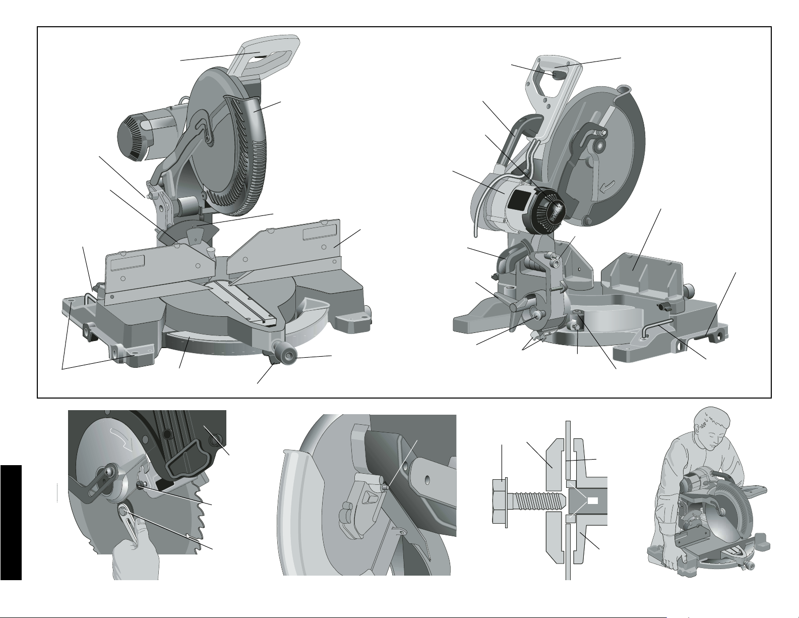
Español
36
FIG. 2
GUARDA
ESCUADRA
DE LADO
DERECHO
PERILLA DE
ABRAZADERA
PASADOR DEL INGLETE
REGLA DE
INGLETE
AGUJEROS PARA
MONTAR BANQUETA
PERILLA PARA SUJE-
TAR A ESCUADRA DE
LADO IZQUIERDO
PASADOR DE
SEGURIDAD
MANILLA DE OPERACIÓN
REGLA DE
BISEL
FIG. 3
FIG. 4
GATILLO
INTERRUPTOR
MANILLA DE
OPERACIÓN
ESCUADRA GUÍA
IZQUIERDA
ESTÁTOR DEL
MOTOR
PALANCAS
DE
ANULACIÓN
DEL BISEL A
45º
CANALÓN
PARA EL
POLVO
TAPA DE
INSPECCIÓN DE
MOTOR
PERILLA DE
ANULACIÓN
DEL BISEL A 0º
PASADOR DE
SEGURIDAD
TOPE DE BISEL –
TRINQUETE DE 33,85º
MANILLA PARA
ACARREAR
LLAVE INGLESA
DE CUCHILLA
TORNILLO DE
AJUSTE DEL
TOPE DE BISEL
A 45º
SEGURO
DE LA
PERILLA
DE BISEL
INDENTACIONES
PARA LA MANO
TORNILLO DE
AJUSTE DE TOPE
DE BISEL A 0º
-DETAIL 1-
-DETAIL 2 -
C
E
F
G
I
H
A
B
D
Page 39

Español
37
FIG. 7
FIG. 6
REGLA
DE
INGLETE
INDICADOR
J
K
T
5. Devuelva el soporte de la protección a su posición
original y ajuste firmemente el tornillo del soporte de la
protección para mantener al soporte en su lugar.
ADVERTENCIA:
• Se debe volver a colocar el soporte de
la protección en su posición original y
se debe ajustar el tornillo antes de
poner en funcionamiento a la sierra.
• El incumplimiento de esta instrucción
podría permitir que la protección se
ponga en contacto con la hoja de la
sierra en rotación provocando daños a
la sierra y daños personales graves.
Transporte de la sierra
¡APAGUE Y DESENCHUFE LA SIERRA DE INGLETES
ANTES DE INTENTAR MOVERLA O HACER EL AJUSTE
QUE SEA!
A fin de mover en forma conveniente la sierra de ingletes de
un lugar a otro, se incluye una manilla para acarrear en la
parte superior del brazo de la sierra e indentaciones para la
mano en la base, tal como se muestra en la Ilustración 4.
Correcciones
HAGA TODOS LOS AJUSTES CUANDO LA SIERRA DE
INGLETES ESTÉ DESENCHUFADA
NOTA: Su sierra de ingletes se regula en forma precisa y
completa en la fábrica en el momento de su fabricación. Si
requiriese una nueva regulación debido al transporte y
empaquetado o por cualquier otra razón, siga los pasos
enumerados abajo para regularla. Una vez hechos, esas
correcciones deben permanecer precisas. Tómese un poco
de tiempo ahora para seguir las directivas cuidadosamente
a fin de mantener la precisión de que es capaz su sierra.
FIG. 5
FIG. 8
Ilustración 2. (Dos agujeros de diferente tamaño que permiten poner tornillos de diferentes tamaños. Use uno u otro
agujero, no es necesario usar los dos.) Siempre monte su
sierra firmemente para prevenir movimiento. A fin de incrementar la portabilidad de su herramienta, puede ser montada en una pieza de madera contrachapada de 1/2" o más
gruesa que puede ser sujetada al soporte de trabajo o
moverse a otro sitio de trabajo y volver a sujetarse.
NOTA: Si usted decide montar la sierra a una pieza de
madera contrachapada, asegúrese de que los tornillos no
salgan por abajo de la madera. El borde de la madera contrachapada debe calzar justo con los bordes del soporte de
trabajo. Al sujetar la sierra a cualquier superficie de trabajo,
sujete solamente en los refuerzos de sujeción donde se
encuentran los agujeros para los tornillos de montaje. Si se
sujeta en cualquier otro sitio de seguro se interferirá con la
operación apropiada de la sierra.
AVISO: Para prevenir ligazón y cortes imprecisos,
asegúrese de que la superficie de montaje no esté deformada ni dispareja por algún motivo. Si la sierra oscila sobre
la superficie ponga un trozo de material delgado debajo de
una pata de la sierra hasta que se asiente con firmeza
sobre la superficie de montaje.
INSTRUCCIONES DE SEGURIDAD
IMPOR
TANTES
Cambio o instalación de una hoja
nueva de sierra
PRECAUCIÓN:
• Nunca oprima el botón de traba de eje mientras la hoja
esté en funcionamiento o en marcha por inercia.
• No utilice esta sierra ingletadora para cortar metales ferrosos (que contengan hierro o acero) o mampostería o
productos de cemento de fibra.
Retiro de la hoja
1. Desenchufe la sierra.
2. Levante el brazo hasta la posición superior y levante la
protección inferior (A) todo lo que sea posible.
3. Afloje, pero no retire el tornillo del soporte de la protección (B) hasta que se pueda levantar suficientemente el
soporte como para tener acceso al tornillo de la hoja.
4. Oprima el botón de traba de eje (C) mientras gira cuidadosamente la hoja de la sierra a mano hasta enganchar
la traba.
5. Manteniendo el botón oprimido, utilice la otra mano y la
llave proporcionada (D) para aflojar el tornillo de la hoja.
(Gire en sentido de las agujas del reloj, rosca de mano
izquierda)
6. Retire el tornillo de la hoja (E), la arandela de
abrazadera externa (F) y la hoja (G). El adaptador de
hoja de 25.4mm (1 pulgada) (H), si se utiliza, y la
arandela de abrazadera interior (I) pueden dejarse en
el eje.
NOTA: El adaptador de hoja de 25.4mm (1 pulgada) no se
utiliza en las hojas que tienen un orificio de hoja de
15.88mm (5/8 pulgadas).
Instalación de la hoja
1. Desenchufe la sierra.
2. Con el brazo levantado, la protección inferior mantenida abierta y la placa de rotación levantada, ubique la
hoja en el eje sobre el adaptador de hoja, si utiliza una
hoja con orificio de hoja de 1 pulgada de diámetro, y
contra la arandela de la abrazadera interna con los
dientes de la parte inferior de la hoja apuntando hacia la
parte de atrás de la sierra.
3. Monte la arandela de abrazadera exterior sobre el eje.
4. Instale el tornillo de la hoja y, enganchando la traba del
eje, ajuste el tornillo firmemente con la llave provista.
(Gire en sentido contrario a las agujas del reloj, roscas
de mano izquierda)
NOTA: Cuando se utilizan hojas con orificio de hoja de
15.88mm (5/8 pulgadas) de diámetro, no se utilizará el
adaptador de hoja y debe guardarse en un lugar seguro.
TORNILLO DE
CORRECCIÓN
DEL INDICADOR
L
M
Page 40

Español
38
FIG. 9
CORRECCIÓN DE LA REGLA DE LA SIERRA (ILUS. 5)
Ponga una escuadra contra la escuadra de guía de la sierra y la cuchilla, tal como se muestra. (No toque las puntas
de los dientes con la escuadra. Al hacerlo causará una
medida inexacta.) Suelte la perilla de la abrazadera (véase
ilustración 9) y gire el brazo de la sierra hasta que el seguro
se fije en la posición de 0º. No apriete la perilla de la
abrazadera. Si la hoja de la sierra no está exactamente perpendicular a la escuadra de guía, suelte los tres tornillos
que sostienen la regla de la sierra a la base y mueva la regla
hacia la izquierda o la derecha hasta que la cuchilla esté
perpendicular a la escuadra de guía, tal como se puede
medir en la escuadra. Vuelva a apretar los tres tornillos. No
preste atención a la medida que aparece en el indicador de
la sierra en este punto.
CORRECCIÓN DEL INDICADOR DE LA SIERRA
(ILUS. 6, 7)
Suelte la perilla de la abrazadera de la sierra (J) haciendo
girar en dirección contraria a las manecillas del reloj y apriete el seguro (K) para mover el brazo hacia la posición cero.
Cuando la perilla de la abrazadera esté suelta, deje que el
seguro se enganche a medida que usted haga rotar el brazo
pasado cero. Observe el indicador y la regla de la sierra a
través de la ranura mostrada en la Ilustración 6. Si el indicador no señala exactamente cero, suelte el tornillo que
mantiene el indicador en su lugar, corrija la posición indicada en el indicador y vuelva a atornillar.
BISEL A ESCUADRA CON LA MESA (ILUS. 8)
A fin de alinear la cuchilla a escuadra con la mesa rotatoria,
enganche el brazo en posición hacia abajo. Ponga la
escuadra contra la hoja teniendo cuidado de no poner la
escuadra sobre alguno de los dientes.
Suelte la perilla de la abrazadera del bisel y asegúrese de
que el brazo esté en la posición de 0º. Mueva el brazo del
bisel lo necesario para que la hoja esté a cero grado con
respecto a la mesa.
INDICADOR DEL BISEL (ILUS. 8)
Si el indicador (M) del bisel no señala cero, suelte el tornillo
que lo sostiene en su lugar y mueva el indicador según sea
necesario. No saque el disco de acero en frente del indicador de bisel. Ese disco impide que la resina de la madera
se acumule en la regla de bisel durante el uso.
CORRECCIÓN DEL TOPE DE BISEL A 45º A LA
IZQUIERDA O DERECHA (ILUS. 9)
NOTA: Ajuste los ángulos de 45º de bisel sólo después
de realizar el ajuste a 0º de ángulo e indicador del bisel.
Asegúrese de que las palancas para anular el bisel de 45º
(N) estén hacia adentro a fin de obtener una corrección
precisa.
Para ajustar el ángulo de bisel a 45º a derecha, suelte la
manilla de fijación del bisel y tire la perilla de anulación del
tope del bisel (Ilus. 2) para anular el tope del bisel a 0º.
Cuando la sierra esté completamente a la derecha, si el
indicador no señala exactamente 45º, gire el tornillo derecho del tope de bisel hasta que el indicador señale 45º.
Para ajustar el tope de bisel a 45º a la izquierda, primero
suelte la manilla de fijación del bisel y ladee la punta a la
izquierda. Si el indicador no señala exactamente 45º, gire el
tornillo del tope de bisel izquierdo hasta que el indicador
señale 45º.
CORRECCIÓN DEL TOPE DE BISEL A 33,85º (ILUS. 9)
NOTA: Ajuste los ángulos de 33,85º de bisel sólo después
de realizar el ajuste a 0º de ángulo e indicador del bisel.
Para fijar el ángulo de bisel a 33,85º, dé vuelta los trinquetes
de tope (P). suelte la manilla de fijación del bisel (Q) y ladee
la punta hacia la izquierda. Si el indicador no señala exactamente 33,85º, haga girar el tornillo que contacta el trinquete hasta que el indicador señale 33,85º.
Para corregir el ángulo de bisel a 33,85º a la derecha, dé
vuelta los trinquetes de tope. Suelte la manilla de fijación del
bisel y tiere el botón de anulación del tope de bisel para anular el tope del bisel a 0º. Cuando la sierra esté completamente a la derecha, si el indicador no señala exactamente
Q
S
R
R
P
U
O
33,85º, haga girar el tornillo que contacta el trinquete hasta
que el indicador señale 33,85º.
REGULACIÓN DE ESCUADRA DE GUÍA
Apague y desenchufe la sierra de ingletes
A fin de que la sierra pueda cortar en bisel a 48 grados a la
izquierda o a la derecha, la escuadra de guía puede regularse para dar espacio. A objeto de regular la escuadra de
guía, suelte la perilla de plásstico que se muestra en la
Ilustración 9 (R) y corra la escuadra hacia afuera. Haga un
ensayo con la sierra apagada y verifique el espacio. Regule
la escuadra de guía para que esté lo más próxima posible
a la hoja como sea práctico para dar el máximo apoyo a la
pieza de trabajo, sin inteferir con el movimiento hacia arriba
y hacia abajo del brazo. Apriete la perilla bien. Cuando se
hayan completado las operaciones de bisel, no olvide
volver a poner la escuadra de guía en su lugar.
NOTA: La ranura guía de las escuadras de guía pueden
quedar obstruidas con aserrín. Si usted percibe que se
están obstruyendo, use una varilla o aire de poca presión
para limpiar las ranuras de guía.
FRENO ELÉCTRICO AUTOMÁTICO
Su sierra está equipada con un freno eléctrico automático
de la cuchilla que para la hoja dentro de 5 segundos
después de accionar el mecanismo que no es regulable.
En ciertas ocasiones, puede haber una demora después de
apretar el gatillo para accionar el freno. En raras ocasiones,
el freno puede no accionar y la cuchilla seguirá corriendo
sola hasta parar.
Si ocurriese una demora o “salto”, encienda y apague la
sierra 4 ó 5 veces. Si la condición persistiese, lleve la herramienta para que un centro de servicio D
EWALT autoriza-
do le haga un mantenimiento.
Siempre confirme que la hoja haya parado antes de retirar-
la del corte. El freno no substituye las guardas ni tampoco
garantiza la seguridad que usted mismo se puede dar prestando completa atención a la sierra.
ACTUACIÓN Y VISIBILIDAD DE LA GUARDA
La guarda de la cuchilla en su sierra ha sido diseñada para
levantarse automáticamente cuando el brazo se baja y para
bajar sobre la cuchilla cuando el brazo esté levantado. La
guarda puede levantarse con la mano al instalar o sacar las
cuchillas o para inspeccionar la sierra.
NUNCA LEVANTE LA GUARDA DE LA CUCHILLA MANUALMENTE A MENOS QUE LA SIERRA ESTÉ APAGADA.
La sección frontal de la guarda es apersianada para tener
visibilidad al cortar. Si bien la persiana reduce mucho el
material que vuela por el aire, son aberturas en la guarda y
se deben usar anteojos de protección en todo momento
cuando esté mirando a través de ellas.
Cepillos
DESCONECTE EL ENCHUFE DEL SUMINISTRO
ELÉCTRICO
Inspeccione los cepillos regularmente desenchufando la
herramienta, sacando la tapa de inspección del motor
N
Page 41

Español
39
(Ilustración 2) y retirando el ensamblaje del cepillo.
Mantenga limpios los cepillos y que se muevan libremente
en sus guías. Siempre reemplace un cepillo usado en la
misma orientación en el sostén tal como estaba antes de
sacarlo. Use sólo cepillos D
EWALT idénticos. Uso del tipo
correcto de cepillo es esencial para el funcionamiento
apropiado del freno eléctrico. Hay ensamblajes de cepillos
nuevos en los centros de servicio D
EWALT. Se debe dejar
que la herramienta “corra sola” (sin carga) por 10 minutos
antes de usar para que los nuevos cepillos se asienten. El
freno eléctrico puede ser errático en su funcionamiento
hasta que los cepillos estén asentados.
Cuando la esté haciendo correr sola NO ATE, PEGUE NI
FIJE DE NINGUNA OTRA FORMA EL GATILLO EN
POSICIÓN DE ENCENDIDO. SOSTENGA CON LA MANO
SOLAMENTE.
Controles
Su sierra de ingletes compuesta tiene varios controles principales, que se describirán brevemente aquí. Para mayor
información sobre esos controles, veánse las respectivas
secciones posteriores del manual.
CONTROL DEL INGLETE (ILUS. 7)
La palanca y el gatillo de ajuste/seguro del inglete permiten
que uno incline el inglete de la sierra 50º a la izquierda y la
derecha. Para tallar en inglete, suelte la manila de fijación
del inglete (T) haciéndolo rotar en dirección contraria a las
manecillas del reloj, apriete el gatillo (K) y fije el ángulo de
inglete deseado en la regla de ingletes. Apriete la manilla de
fijación del inglete haciéndola rotar en la dirección de las
manecillas del reloj.
INTERRUPTOR DE GATILLO
El interruptor de gatillo (Ilus. 2) enciende y apaga su sierra.
Se provee un agujero en el gatillo para insertar un candado
a fin de proteger la sierra.
FIJACIÓN DEL BISEL (ILUS. 9)
La manilla de fijación del bisel (Q) le permite a usted poner
el bisel de la sierra a 48º a la izquierda o la derecha. Para
soltar la manilla y ajustar el valor del bisel, gire la manilla en
dirección contraria a las manecillas del reloj, la punta de la
sierra se inclina en bisel fácilmente a la izquierda o la
derecha una vez que se tira de la perilla (S) para anular el
bisel de 0º. Para apretar, gire la manilla en dirección de las
manecillas del relok. En la parte inferior al frente del brazo
de la sierra se encuentran las marcas de los grados de
bisel. (T- Ilus. 7)
ANULACIÓN DE BISEL DE 0º (ILUS. 9)
La anulación del tope de bisel (S) le permite a usted poner
la sierra en bisel a la derecha pasado la marca de 0º.
La sierra parará automáticamente a 0º cuando se torna de
la izquierda. Para pasar de 0º hacia la derecha, tire la perilla de tope del bisel. La perilla de tope puede no accionar si
no tira la perilla y rotándola en 180º.
CORTE INADECUADO
CORTE INADECUADO
CORTE ADECUADO
FIG. 10
CORTE ADECUADO
FIG. 10A
FIG. 10B
FIG. 10C
Page 42

Español
40
ANULACIÓN DEL TOPE DE BISEL DE 45º (ILUS. 9)
La anulación del tope de bisel se mantienen en posición con
el tornillo de acoplamiento para prevenir un movimiento
inadvertido. Use la punta en la llave para soltar el tornillo de
adhesión. Eso permite que las reglas se tiren hacia afuera y
la cabeza de la sierra torne pasado la marca de 45º.
Asegúrese de volver a apretar el tornillo de acoplamiento
cuando termine.
TOPES DE BISEL A 33,85º (ILUS. 9)
Los dos trinquetes (P) se usan para parar el valor de bisel de
la sierra en 33,85º. Este valor se usa principalmente para
cortar molduras coronadas puestas de plano sobre la mesa.
PASADOR DE SEGURIDAD DEL CABEZAL (ILUS. 9)
Para fijar el cabezal de la sierra en posición hacia abajo,
presione el cabezal hacia abajo, haga entrar el pasador (U)
y suelte el cabezal de la sierra. Eso mantendrá el cabezal
de la sierra en posición hacia abajo para mover la sierra de
un lugar a otro. Cuando quiera soltar, presione el cabezal
hacia abajo y saque el pasador.
Funcionamiento
Enchufe la sierra en un tomacorrientes de 60 Hz. Consulte
la placa del fabricante para ver el voltaje. Asegúrese de que
el cordón no vaya a interferir con su trabajo.
INTERRUPTOR
Para encender la sierra, apriete el gatillo interruptor. Para
apagar la herramienta, suelte el gatillo. Deje que la hoja
acelere hasta que alcance las RPM necesarias para operar
antes de hacer un corte. Suelte el gatillo interruptor y deje
que el freno pare la hoja antes de levantar el cabezal de la
sierra. No hay modo de fijar el gatillo en posición encendi-
CORTES DE BISEL
Un corte de bisel es un corte trasversal con una cuchilla de
sierra a un ángulo con respecto a la madera. A fin de fijar el
ángulo, suelte la perilla de la abrazadera del bisel y mueva
la hoja a la izquierda según se desee. (Es necesario mover
la escuadra de guía para dejar espacio). Una vez que se
tiene el ángulo del bisel, apriete firmemente la perilla de la
abrazadera del bisel.
Los ángulos de bisel se pueden poner entre 48 grados a la
derecha y hasta 48 grados a la izquierda y se puede cortar
con el brazo de la sierra puesto entre cero y 50 grados a la
derecha o izquierda. En algunos ángulos extremos, será
necesario sacar la escuadra ajustable de guía de la izquierda o la derecha. Para sacar la escuadra de guía de la
derecha o de la izquierda, desatornille las perillas variass
vueltas y deslice la escuadra hacia afuera.
CALIDAD DEL CORTE
La lisura de un corte depende de una serie de variables.
Cosas tales como el material que se esté cortando, el tipo
de cuchilla, el filo de la hoja y la velocidad del corte contribuyen a la calidad de éste. Cuando se desee el corte más
liso posible para hacer molduras o algún otro trabajo de precisión, una cuchilla afilada (60 dientes de carburo) y una
velocidad más lenta y pareja de corte producirán los resultados deseados. Asegúrese de que el material no se arrastre mientras se hace el corte. Sujételo firmemente en su
lugar. Siempre deje que la cuchilla pare completamente
antes de levantar el brazo.
Si pequeñas fibras de madera siguen saliendo por la parte
de atrás de la pieza, aplique a ésta una cinta adhesiva sobre
la madera donde se hará el corte. Aserruche sobre la cinta
y cuidadosamente sáquela cuando se haya terminado el
corte.
Para diversas aplicaciones de cortar, consulte la lista de
cuchillas recomendadas para su sierra y seleccione la que
mejor convenga a sus necesidades (página 35).
POSICIÓN DEL CUERPO Y LAS MANOS
(ILUS. 10)
La postura apropiada del cuerpo y las manos cuando se esté
operando la sierra de ingletes le facilitará la acción, la hará
más segura y más precisa. Nunca ponga las manos cerca
del área del corte. No ponga las manos a menos de 6” de la
hoja. Sostenga la pieza de trabajo firmemente a la mesa y la
escuadra de guía cuando esté cortando. Mantenga las
manos en posición hasta que se suelte el gatillo y la hoja se
haya detenido completamente. SIEMPRE HAGA ENSAYOS
(SIN ELECTRICIDAD) ANTES DE HACER CORTES DE
ACABADO DE MODO QUE VERIFIQUE EL TRAYECTO
DE LA CUCHILLA. NO CRUCE LAS MANOS, TAL COMO
SE MUESTRA EN LA ILUSTRACIÓN 10A.
Mantenga los dos pies firmemente puestos sobre el suelo y
mantenga un equilibrio apropiado. A medida que vaya
moviendo el brazo de la sierra a izquierda y derecha, sígala
y párese ligeramente a un lado de la cuchilla. Mire a través
de las persianas cuando siga una línea dibujada a lápiz.
FIG. 11 FIG. 12
FIG. 13
A.
B.
ÁNGULO “A”
FIG. 14
REGLA DE
INGLETE
do, pero se provee un agujero en el gatillo para insertar un
candado a fin de bloquear la sierra en posición de apagado.
CORTANDO CON SU SIERRA
NOTA: Si bien esta sierra corta madera y muchos materi-
ales no ferrosos, limitaremos nuestra exposición al corte de
madera solamente. Las mismas directrices se aplican a los
demás materiales. NO CORTE MATERIALES FERROSOS
(HIERRO Y ACERO) NI ALBAÑILERÍA CON ESTA SIERRA. No use ninguna hoja abrasiva.
CORTES TRASVERSALES
No se recomienda cortar varias piezas a la vez, pero se
puede hacer sin peligro asegurando que cada pieza esté
sujeta firmemente contra la mesa y la escuadra de guía. Se
hace un corte trasversal cortando la madera a través de las
estrías en cualquier ángulo. Un corte trasversal recto se
hace con el brazo de la sierra de ingletes en la posición de
cero grado. Ponga el brazo de la sierra a cero, sostenga la
madera sobre la mesa y firmemente contra la escuadra de
guía. Encienda la sierra apretando el gatillo interruptor.
Cuando la sierra gane velocidad (cerca de 1 segundo) baje
el brazo suave y lentamente para cortar la madera. Deje
que la cuchilla pare completamente antes de levantar el
brazo.
Los cortes a inglete se hacen con el brazo de la sierra a un
cierto ángulo que no sea cero. Ese ángulo es a menudo de
45 grados para hacer esquinas, pero se puede poner en
cualquiera posición entre cero y 50 grados a izquierda o
derecha. Después de seleccionar el ángulo de inglete
deseado, asegúrese de apretar la perilla de la abrazadera.
Haga el corte tal como se describe arriba.
Page 43

Español
41
V1
V2
BRAZO DE
SIERRA DE
INGLETE
MARCA CENTRAL DE NINIO SE ALINEA CON LA MARCA
DEL GRADO ENTERO MÁS CERCANO EN LA REGLA DE
INGLETES (24º INGLETE A LA DERECHA)
MARCA DE _º DE NINIO SE ALINEA CON LA MARCA DEL
GRADO ENTERO MÁS CERCANO EN LA REGLA DE
INGLETES (24 1/4º INGLETE A LA DERECHA)
PLACA
DE
CORTE
SUJETAMIENTO DE LA PIEZA
Apague y desenchufe la sierra
Si no puede sujetar la pieza de trabajo sobre la mesa y contra la escuadra de guía con la mano (forma irregular, etc.) o
su mano quedara a menos de 6” de la hoja, se debe usar
una abrazadera o algún otro dispositivo.
Para obtener los mejores resultados use la abrazadera
DW7082 hecha para usarse con su sierra. Se encuentra
disponible por intermedio de su distribuidor local o el centro
de servicio D
EWALT con costo extra.
Otros aparatos auxiliares tales como abrazaderas de
resorte, de barra o abrazaderas-C pueden ser apropiados
para ciertos tamaños y formas de material. Tenga cuidado
al seleccionar y poner esas abrazaderas. Tómese el tiempo
para hacer un ensayo antes de cortar. La escuadra de guía
izquierda o derecha se mueve de un lado a otro para asistir
a sujetar.
SOPORTE DE PIEZAS LARGAS
Apague y desenchufe la sierra
SIEMPRE APOYE LAS PIEZAS LARGAS
Para obtener los mejores resultados use el soporte de exten-
sión DW7080 a fin de extender el ancho de la mesa de su
sierra. Disponible a la venta en su concesionario con costo
extra. Apoye las piezas largas usando cualquier medio conveniente tal como caballetes de aserrar o aparatos similares
para impedir que se caigan los extremos.
CORTE DE MARCOS DE CUADROS,
ENMARCAMIENTO DE CAJA Y OTROS
PROYECTOS DE CUATRO LADOS
Para comprender mejor cómo hacer los objetos mencionados arriba, sugerimos que intente hacer unos proyectos
simples usando madera de sobra hasta que usted capte
como funciona la sierra. Su sierra es la herramienta perfecta para cortar esquinas como las que se muestran en la
Ilustración 12. El diagrama A en la Ilustración 11 muestra
un empalme hecho usando el bisel para cortar en bisel los
borde de dos láminas a 45º cada una con el fin de producir
una esquina de 90º. Para este empalme el brazo se puso en
posición cero y el bisel se fijó en 45º. La madera se puso
con el lado ancho contra la mesa y el borde angosto contra
la escuadra. El corte se podía también haber hecho cortando a inglete a derecha e izquierda con la superficie ancha
contra la escuadra de guía.
CORTANDO MOLDURAS DE ARQUITRAVES Y OTRAS
ENMARCACIONES
El diagrama B en la Ilustración 11 muestra un empalme
hecho poniendo el brazo a 45º para cortar dos planchas con
el fin de formar una esquina de 90º. Para hacer este tipo de
empalme, ponga el bisel a cero y la guía de inglete a 45º.
Reiteramos, la posición de la madera está con el lado ancho
y plano sobre la mesa y el borde delgado contra la escuadra
de guía.
Los dos diagramas en la Ilustración 11 son para objetos de
cuatro lados solamente. Como el número de lados cambia,
FIG. 15
así también cambian los ángulos de ingletes y de bisel. La
lista de abajo da los ángulos apropiados para una variedad
de formas. (La lista supone que todos los lados son de igual
longitud.) Para una figura que no se muestre en el cuadro,
use la siguiente fórmula. 180º dividido por el número de
lados es igual al ángulo de inglete o de bisel.
EJEMPLOS
Nº DE LADOS ÁNGULO DE INGLETE O BISEL
445°
536°
630°
7 25,7°
8 22,5°
920°
10 18°
CORTE DE INGLETES COMPUESTOS
Un inglete compuesto se corta usando un ángulo de inglete
y un ángulo de bisel al mismo tiempo. Este es el tipo de
corte usado para hacer marcos o cajas con lados inclinados
como el que se muestra en la Ilustración 13.
NOTA: Si el ángulo de corte varía de corte a corte, verifique
que la perilla de la abrazadera del bisel y del fijador del
inglete estén bien apretadas. Esas perillas deben estar
apretadas después de hacer cualquier cambio en el bisel o
inglete.
La tabla de la página 43 lo ayudará a seleccionar los valores
del bisel y el inglete apropiados para cortes corrientes de
inglete compuesto. Para usar la tabla, seleccione el ángulo
deseado “A” (Ilustración 13) de su proyecto y ubique el
ángulo en el arco apropiado en la tabla. Desde ese punto
siga la tabla derecho hacia abajo para encontrar el ángulo
de bisel correcto y en forma lateral para encontrar el ángulo de inglete correcto.
Ponga su sierra a los ángulos prescritos y haga algunos
cortes de ensayo. Practique empalmando las piezas cortadas hasta que capte la idea de este procedimiento y se
sienta cómodo con él.
Ejemplo: Para hacer una caja de cuatro lados con ángulos
exteriores de 26º (Ángulo A, Ilustración 13), use el arco
superior derecho. Encuentre 26º en la escala del arco.
Siga la línea horizontal que intersecta la línea para uno u
otro lado a fin de obtener el valor del ángulo de inglete en
la sierra (42º).
Del mismo modo, siga la línea vertical que intersecta hacia
arriba o hacia abajo para obtener el ángulo de bisel en la
sierra (18º).
Siempre ensaye los cortes con unas piezas de sobra a fin
de verificar la posición en la sierra.
ESCALA DE NONIO
Su sierra está equipada con una escala de nonio para
mayor precisión. La escala de nonio le permite fijar con precisión ángulos de inglete al 1/4 de grado más próximo (15
minutos). Para usar la escala de nonio siga los pasos
descritos abajo.
Page 44

Español
42
FIG. 16
(Como un ejemplo, supongamos que usted desea cortar a
inglete en un ángulo de 24 1/4 grados a la derecha).
1. Apague la sierra de ingletes.
2. Fije el ángulo de inglete al grado entero más próximo
deseado alineando la marca central en la escala de
ninio, en la ilustración VI, con el grado entero marcado
en la escala de ingletes. Examine la Ilustración V2
detenidamente; el valor señalado es 24 grados en
inglete a la derecha.
3. Para fijar el 1/4 grado adicional, apriete el fijador del
brazo y muévalo cuidadosamente hacia la DERECHA
hasta que la marca de 1/4 grado ninio se alinee con la
marca del grado MÁS CERCANO en la regla de ingletes.
En nuestro ejemplo, la marca del grado más cercano en
la regla de ingletes es de 25º. La ilustración V2 muestra
un valor de 24 1/2 grados de inglete a la derecha.
Para fijar valores que exigen fracciones de grado (1/4 , 1/2,
3/4 grados) alinee la marca de ninio deseada con la marca
del grado MÁS CERCANO en la regla de ingletes, tal como
se describe arriba (el disco de plástico de ninio tiene inscritos
marcas para 1/4, 1/2, 3/4 y 1 grado. Sólo 1/2 de grado está
señalado numéricamente.)
CUANDO CORTE A INGLETE HACIA A DERECHA
A fin de aumentar el ángulo de inglete cuando se corta a la
derecha, mueva el brazo para alinear la marca de ninio
apropiada con la marca más cercana del brazo a la derecha.
A fin de disminuir el ángulo del inglete cuando corte a la
derecha, mueva el brazo para alinear la marca de ninio
apropiada con la marca más cercana en la guía de ingletes
a la izquierda.
CUANDO CORTE A INGLETE HACIA LA IZQUIERDA
A fin de aumentar el ángulo de inglete cuando se corta a la
izquierda, mueva el brazo para alinear la marca de ninio
apropiada con la marca más cercana del brazo a la izquierda. A fin de disminuir el ángulo del inglete cuando corte a la
izquierda, mueva el brazo para alinear la marca de ninio
apropiada con la marca más cercana en el brazo a la
derecha.
CUANDO CORTE UNA MOLDURA DE BASE
SIEMPRE HAGA UN ENSAYO SIN ELECTRICIDAD
ANTES DE HACER UN CORTE.
Cortes rectos a 90º:
Ponga la madera contra la escuadra de guía tal como se
muestra en la Ilustración 15. Encienda la sierra, deje que la
cuchilla alcance su plena velocidad y baje el brazo calmadamente para cortar.
CORTAR MOLDURA DE BASE DE HASTA 6” DE ALTURA
VERTICALMENTE CONTRA LA ESCUADRA DE GUÍA
Ponga la moldura tal como se muestra en la ilustración 15.
Todos los cortes se hacen con la parte de atrás de la moldu-
ra contra la escuadra de guía y la parte inferior de la moldura contra la base.
FIG. 17
ESCUADRA DE GUÍA
MESA
MOLDURA CORONADA PLANA SOBRE LA MESA Y CONTRA
LA ESCUADRA DE GUÍA
MOLDURA CORONADA ENTRE LA ESCUADRA GUÍA
Y LA MESA
MESA
ESCUADRA
DE GUÍA
LADO DE ABAJO
DE LA MOLDURA
LADO SUPERIOR
DE LA MOLDURA
FIG. 17A
CORONA
DW7084
ESQUINA INTERIOR:
Lado izquierdo
1. Inglete izquierdo de 45º
2. Guarde lado izquierdo del corte
Lado derecho
1. Inglete derecho de 45º
2. Guarde lado derecho del corte
ESQUINA EXTERIOR:
Lado izquierdo
1 Inglete izquierdo de 45º
2. Guarde lado izquierdo del corte
Lado derecho
1. Inglete derecho de 45º
2. Guarde lado derecho del corte
Se puede cortar material de hasta 6” tal como se describe
arriba.
CORTE DE MOLDURAS CORONADAS
Su sierra de ingletes está mejor capacitada para la tarea de
cortar molduras coronadas que ninguna otra herramienta
fabricada. A fin de que calce apropiadamente, la moldura
coronada debe cortarse en forma compuesta con extrema
precisión.
Las dos superficies planas de una pieza de moldura coronada están a ángulos que suman exactamente 90 grados. La
mayoría, pero no todas, de las molduras coronadas tiene un
ángulo superior trasero (la sección que calza plana contra el
cielo ) de 52 grados y un ángulo inferior trasero (la parte que
calza contra la pared) de 38 grados. Su sierra de ingletes
tiene puntos de pasador preprogramados a 31,62 grados de
izquierda y derecha para cortar molduras coronadas al
ángulo apropiado. También hay una marca sobre la regla
de bisel a 33,85 grados.
La tabla de abajo da las posiciones apropiadas para cortar
molduras coronadas. (Los números de las posiciones de
ingletes y biseles son muy precisas y no son fáciles de fijar
con exactitud en su sierra.) Dado que la mayoría de las
habitaciones no tiene ángulos de precisamente 90 grados,
usted debe de todas maneras afinar las posiciones.
¡ES EXTREMADAMENTE IMPORTANTE ENSAYAR
PREVIAMENTE CON MATERIAL DE SOBRA!
INSTRUCCIONES PARA CORTAR MOLDURAS CORONADAS PUESTAS PLANAS Y USANDO DISPOSITIVOS
COMPUESTOS
1. Moldura puesta con la superficie plana hacia abajo
sobre la mesa de la sierra (Ilustración 17).
2. Las posiciones que aparecen abajo son para las
molduras coronadas estándar (EE.UU.) con ángulos de
52º y 38º.
Page 45

Español
43
TABLA 1 CORTE DE INGLETE COMPUESTO
AJUSTE ESTE ANGULO DE INGLETE EN LA SIERRA
CAJA CUADRADA
CAJA HEXAGONAL
AJUSTE ESTE ANGULO DE BISELEN LA SIERRA
CAJA OCTAGONAL
10
20
30
10
20
30
10
20
30
40
40
50
60
40
50
60
70
50
60
70
80
70
80
80
Page 46

Español
44
VALOR DE BISEL TIPO DE CORTE
Izquierdo 33,85º LADO IZQUIERDO,
ESQUINA INTERIOR:
1. Parte superior de la moldura contra
la
escuadra de guía
2. Mesa de la sierra puesta en 31,62º a
la derecha
3. Guarde el corte de la izquierda
Derecho 33,85º LADO DERECHO, ESQUINA
INTERIOR:
1. Parte superior de la moldura contra
la escuadra de guía
2. Mesa de la sierra puesta en 31,62º a
la izquierda
3. Guarde el corte de la derecha
Derecho 33,85º LADO IZQUIERDO, ESQUINA
EXTERIOR:
1. Parte superior de la moldura contra
la escuadra de guía
2. Mesa de la sierra puesta en 31,62º a
la izquierda
3. Guarde el corte de la izquierda
Izquierdo 33,85º LADO DERECHO, ESQUINA
EXTERIOR:
1. Parte superior de la moldura contra
la escuadra de guía
2. Mesa de la sierra puesta en 31,62º a
la derecha
3. Guarde el corte de la derecha
Al fijar los ángulos de bisel y de inglete para todos los cortes
compuestos, recuerde que:
Los ángulos presentados para las moldurass coronadas
son muy precisos y difíciles de fijar con precisión. Dado que
pueden cambiar fácilmente y muy pocas habitaciones
tienen exactamente las esquinas cuadradas, todas las posiciones se deben probar con molduras desechadas.
¡ES EXTREMADAMENTE IMPORTANTE ENSAYAR CON
MATERIAL DESECHADO!
MÉTODO ALTERNATIVO PARA CORTAR MOLDURAS
CORONADAS
Ponga la moldura sobre la mesa a un ángulo entre la
escuadra y la mesa de la sierra, tal como se muestra en la
Ilustración 17A. Se recomienda mucho que use el accesorio de escuadra para molduras coronadas (DW7084) debido
al grado de exactitud y su conveniencia. El accesorio de
escuadra para molduras coronadas está disponible con
costo extra en su concesionario local. La ventaja de cortar
la moldura coronada mediante el uso de este método es
que se hace innecesario hacer el corte de bisel. Cambios
mínimos en el ángulo de inglete pueden hacerse sin afectar
el ángulo de bisel. De esta manera, cuando se encuentren
esquinas que no sean de 90 grados, la sierra puede ajus-
ESQUINA INTERIOR:
Lado izquierdo
1. Corte a inglete a la derecha a 45º
2. Guarde el lado derecho del corte
Lado derecho
1. Corte a inglete a la izquierda a 45º
2. Guarde el lado izquierdo del corte
ESQUINA EXTERIOR
Lado izquierdo
1. Corte a inglete a la izquierda a 45º
2. Guarde el lado derecho del corte
Lado derecho
1. Corte a inglete a la derecha a 45º
2. Guarde el lado izquierdo del corte
FIG. 20
FIG. 21
CORRECTO
INCORRECTO
FIG. 19
CUCHILLA
ESCUADRA DE
GUÍA
INCORRECTO
FIG. 18
CUCHILLA
ESCUADR
A DE GUÍA
CORRECTO
tarse rápida y fácilmente a ellos. Use el accesorio de
escuadra para molduras coronadas a fin de mantener el
ángulo al que estará la moldura en la pared.
INSTRUCCIONES PARA CORTAR MOLDURAS CORONADAS A ÁNGULOS ENTRE LA ESCUADRA Y LA BASE
DE LA SIERRA PARA TODOS LOS CORTES:
1. Ponga la moldura a un ángulo de modo que la parte
inferior de la moldura (la parte que va contra la pared
cuando se instala) esté contra la escuadra y la parte
superior de la moldura descanse sobre la base de la
sierra, tal como se muestra en la Ilustración 17A.
2. Los “planos” angulados en la parte de atrás de la moldura deben descansar directamente sobre la escuadra y la
base de la sierra.
Page 47

Español
45
D
EWALT u otras organizaciones autorizadas. Estas organi-
zaciones prestan servicio a las herramientas D
EWALT y
emplean siempre refacciones legitimas D
EWALT.
Póliza de Garantía
IDENTIFICACIÓN DEL PRODUCTO:
Sello o firma del Distribuidor.
Nombre del producto: _________Mod./Cat.: ___________
Marca: ________________Núm. de serie:_____________
(Datos para ser llenados por el distribuidor)
Fecha de compra y/o entrega del producto: ___________
Nombre y domicilio del distribuidor donde se adquirió
el producto:
_____________________________________________
Este producto está garantizado por un año a partir de la
fecha de entrega, contra cualquier defecto en su funcionamiento, así como en materiales y mano de obra
empleados para su fabricación. Nuestra garantía incluye la
reparación o reposición del producto y/o componentes sin
cargo alguno para el cliente, incluyendo mano de obra,
así como los gastos de transportación razonablemente
erogados derivados del cumplimiento de este certificado.
Para hacer efectiva esta garantía deberá presentar su
herramienta y esta póliza sellada por el establecimiento
comercial donde se adquirió el producto, de no contar con
ésta, bastará la factura de compra.
EXCEPCIONES.
Esta garantía no será válida en los siguientes casos:
• Cuando el producto se hubiese utilizado en condiciones
distintas a las normales;
• Cuando el producto no hubiese sido operado de acuerdo con el instructivo de uso que se acompaña;
• Cuando el producto hubiese sido alterado o reparado
por personas distintas a las enlistadas al final de este
certificado.
Anexo encontrará una relación de sucursales de servicio de
fábrica, centros de servicio autorizados y franquiciados en la
República Mexicana, donde podrá hacer efectiva su garantía y adquirir partes, refacciones y accesorios originales.
Garantía limitada por tres años
DEWALT reparará, sin cargo, cualquier falla que surja de
defectos en el material o la fabricación del producto, por
hasta tres años a contar de la fecha de compra. Esta garantía no cubre fallas de las piezas causadas por su desgaste
normal o abuso a la herramienta. Para mayores detalles
sobre la cobertura de la garantía e información acerca de
reparaciones realizadas bajo garantía, visítenos en
www.dewalt.com o dirígase al centro de servicio más cercano. Esta garantía no aplica a accesorios o a daños causados por reparaciones realizadas o intentadas por terceros. Esta garantía le otorga derechos legales específicos,
además de los cuales puede tener otros dependiendo del
estado o provincia en que se encuentre.
Cortes especiales
NUNCA HAGA NINGÚN CORTE A MENOS QUE EL
MATERIAL ESTÉ SUJETO A LA MESA Y CONTRA LA
ESCUADRA
CORTE DE ALUMINIO:
SIEMPRE USE LA CUCHILLA APROPIADA HECHA
ESPECIALMENTE PARA CORTAR ALUMINIO. Estas se
encuentran disponibles a la venta en su distribuidor
DEWALT o centro de servicio D
EWALT. Ciertas piezas de
trabajo, debido a su tamaño, forma o acabado de superficie,
pueden exigir el uso de una abrazadera o dispositivo para
prevenir que se muevan durante el corte. Ponga el material
de modo que usted corte una sección trasversal muy fina,
tal como se muestra en la Ilustración 18. La Ilustración 19
muestra la forma equivocada de cortar esas extrusiones.
Use la barra de lubricante de cera cuando corte aluminio.
Aplique la barra de cera directamente a la hoja de la sierra
antes de cortar. Nunca aplique la barra de cera a una hoja
en movimiento. La cera, disponible en la mayoría de las ferreterías y casas de abastecimiento para talleres industriales, proporciona la lubricación adecuada y hace que las
astillas no se adhieran a la cuchilla. Sujete la pieza de trabajo en forma apropiada. Consulte la página 37 para ver
sobre la cuchilla correcta.
Material arqueado:
Cuando corte material arqueado siempre póngalo tal como
se muestra en la Ilustración 20 y nunca como se muestra en
la Ilustración 21.
Si el material se pone en forma incorrecta se causará que
apriete la hoja cerca del final del corte.
Corte de tubo plástico o algún otro material redondo
El tubo de plástico se puede cortar fácilmente con su sierra.
Se debe cortar tal como la madera y SE DEBE SUJETAR
O MANTENER FIRMEMENTE A LA ESCUADRA DE QUÍA
PARA IMPEDIR QUE RUEDE. Esto es extremadamente
importante cuando se hacen cortes a ángulo.
Corte de material grande
Ocasionalmente usted encontrará una pieza de madera un
poco demasiado grande para caber debajo de la guarda de
la hoja. Se puede obtener un poco más de altura subiendo
la guarda un tanto para sacarla del paso, tal como se muestra en la Ilustración 24. Evite hacer esto lo más posible, pero
si llega el caso, la sierra funcionará en forma apropiada y
hará el corte más grande. NUNCA AMARRE, FIJE CON
UNA CINTA ADHESIVA NI SOSTENGA DE ALGUNA
OTRA FORMA LA GUARDA ABIERTA CUANDO TRABAJE CON LA SIERRA.
Saque y cambio de la correa
La correa está diseñada para durar todo el tiempo que dure
la herramienta. No obstante, el uso excesivo de ésta causa
la rotura de la correa. Si la hoja no da vueltas cuando el
motor está andando, la correa se ha roto. A fin de inspeccionar o cambiar la correa, saque los tornillos de la cubierta
de la correa. Saque la cubierta de la correa. Inspeccione la
correa para ver si está gastada o está rota. Verifique la tensión de la correa apretándola tal como se muestra en la ilustración 22. Las mitades de la correa deberían casi tocarse
cuando se aprieta firmemente con el dedo pulgar y el índice.
A fin de ajustar la tensión, suelte, pero no saque, los cuatro
tornillos Phillips mostrados. Luego rote el tornillo fijo en la
parte superior de la placa del motor hasta lograr la tensión
apropiada. Atornille los cuatro tornillos firmemente y vuelva
a poner la cubierta de la correa.
NOTA: Si la correa se pone demasiado apretada se ocasionará la falla prematura del motor.
Mantenimiento
1. Todos los rodamientos están sellados. Están lubricados
de por vida y no requieren más mantenimiento.
2. Periódicamente limpie el polvo y las astillas de madera
alrededor y DEBAJO de la base y la mesa rotatoria. Aun
cuando hayan ranuras para dejar que los desechos pase
por ahí, siempre se acumula un poco de polvo.
3. Los cepillos están diseñados para darle varios años de
servicio. Si alguna vez necesita reemplazarlos siga las
instrucciones en la página 38 o lleve la herramienta al
centro de servicio más cercano para que la reparen.
Una lista de direcciones de centros de servicio se adjunta a su herramienta.
Reparaciones
Para garantizar la SEGURIDAD y la CONFIABILIDAD,
deberán hacerse reparaciones, mantenimiento y ajustes de
esta herramienta en los centros autorizados de servicio
TORNILLO
FIJADOR
TORNILLOS
FIG. 22
Page 48

Español
46
Además de la garantía, las herramientas D
EWALT están
cubiertas por:
1 AÑO DE SERVICIO GRATUITO
DEWALT mantendrá la herramienta y reemplazará las
piezas gastadas por su uso normal, sin cobro, en cualquier
momento durante un año a contar de la fecha de compra.
GARANTÍA DE REEMBOLSO DE SU DINERO
POR 90 DÍAS
Si no está completamente satisfecho con el desempeño de
su máquina herramienta, láser o clavadora D
EWALT,
cualquiera sea el motivo, podrá devolverlo hasta 90 días de
la fecha de compra con su recibo y obtener el reembolso
completo de su dinero – sin necesidad de responder a
ninguna pregunta.
PRODUCTO REACONDICIONADO: Los productos reacondicionados están cubiertos bajo la Garantía de 1 Año de
Servicio Gratuito. La Garantía de 90 Días de Reembolso de
su Dinero y la Garantía Limitada de Tres Años no aplican a
productos reacondicionados.
SUSTITUCIÓN GRATUITA DE LAS ETIQUETAS DE
ADVERTENCIA: Si sus etiquetas de advertencia se vuel-
ven ilegibles o se pierden, llame al 1-800-544-6986 para
conseguir repuestos gratuitos.
PARA REPARACION Y SERVICIO DE SUS
HERRAMIENTAS ELÉCTRICAS, FAVOR DE DIRIGIRSE
AL CENTRO DE SERVICIO MAS CERCANO
CULIACAN, SIN
Av. Nicolás Bravo #1063 Sur Col. Industrial Bravo (667) 7 12 42 11
GUADALAJARA, JAL
Av. La Paz #1779 Col. Americana Sector Juárez (33) 3825 6978
MEXICO, D.F.
Eje Central Lázaro Cárdenas No. 18
Local D, Col. Obrera (55) 5588 9377
MERIDA, YUC
Calle 63 #459-A - Col. Centro (999) 928 5038
MONTERREY, N.L.
Av. Francisco I. Madero No.831 - Col. Centro (81) 8375 2313
PUEBLA, PUE
17 Norte #205 - Col. Centro (222) 246 3714
QUERETARO, QRO
Av. Madero 139 Pte. - Col. Centro (442) 214 1660
SAN LUIS POTOSI, SLP
Av. Universidad 1525 - Col. San Luis (444) 814 2383
TORREON, COAH
Blvd. Independencia, 96 Pte. - Col. Centro (871) 716 5265
VERACRUZ, VER
Prolongación Díaz Mirón #4280 - Col. Remes (229) 921 7016
VILLAHERMOSA, TAB
Constitución 516-A - Col. Centro (993) 312 5111
PARA OTRAS LOCALIDADES LLAME AL: (55) 5326 7100
IMPORTADOR: DEWALT S.A. DE C.V.
BOSQUES DE CIDROS ACCESO RADIATAS NO. 42
COL. BOSQUES DE LAS LOMAS, 3A. SECCIÓN, CP 05120
DELEGACIÓN CUAJIMALPA, MÉXICO, D.F
TEL. 5 326 7100
R.F.C.: BDE810626-1W7
Para servicio y ventas consulte
“HERRAMIENTAS ELECTRICAS”
en la sección amarilla.
Información Técnica
DW706
Tensión de alimentación: 120 V AC
Consumo de corriente: 15 A
Frecuencia de alimentación: 60 Hz
Rotación sin carga: 4 000/min
Page 49

Español
47
Guía para resolver problemas
ASEGÚRESE DE SEGUIR LAS NORMAS E INSTRUCCIONES DE SEGURIDAD
¡PROBLEMA! LA SIERRA NO ENCIENDE
¿QUÉ PASA? QUÉ HACER…
1. La sierra no está enchufada 1. Enchufe la sierra
2. El fusible se rompió o el interruptor se movió 2. Cambie el fusible o ponga el interruptor en su posición correcta.
3. El cordón está dañado 3. Haga que el centro de servicio autorizado cambie el cordón.
4. Los cepillos están gastados 4. Haga que el centro de servicio autorizado cambie los cepillos o
reemplácelos usted mismo siguiendo las instrucciones de la página 38.
¡PROBLEMA! LA SIERRA HACE CORTES INSATISFACTORIOS
¿QUÉ PASA? QUÉ HACER…
1. Cuchilla sin filo 1. Cambie la cuchilla. Véase página 37.
2. La cuchilla está montada al revés 2. Dé vuelta la cuchilla. Véase página 37.
3. Goma o resina en la hoja 3. Saque la hoja y límpiela con aguarrás y virutilla de acero o algún limpiador casero.
4. Cuchilla incorrecta para el trabajo que se está haciendo 4. Cambie el tipo de cuchilla. Véase página 35.
¡PROBLEMA! LA CUCHILLA NO ALCANZA VELOCIDAD
¿QUÉ PASA? QUÉ HACER…
1. El cordón de extensión es demasiado ligero o demasiado largo. 1. Reemplace con un cordón de dimensión adecuada. Véase página 32.
2. Baja corriente en la casa 2. Contacte la compañía de electridad.
¡PROBLEMA! LA MÁQUINA VIBRA EXCESIVAMENTE
¿QUÉ PASA? QUÉ HACER…
1. La sierra no está montada bien al soporte o mesa de trabajo. 1. Apriete dispositivos de montaje. Véase página 35.
2. El soporte o mesa está sobre piso disparejo 2. Ponga en una superficie plana. Véase página 35.
3. La cuchilla de la sierra está dañada 3. Cambie la cuchilla. Véase página 37.
¡PROBLEMA! NO HACE CORTES A INGLETE PRECISOS
¿QUÉ PASA? QUÉ HACER…
1. La regla de inglete no está correctamente ajustada 1. Verifique y cambie. Véase página 38.
2. La cuchilla no está en ángulo recto con la escuadra de guía 2. Verifique y cambie. Véase página 38.
3. La cuchilla no está perpendicular a la mesa 3. Verifique y corrija la escuadra. Véase página 38.
4. La pieza de trabajo se mueve 4. Sujete la pieza firmemente a la escuadra de guía o pegue lija 120 a la escuadra
guía con un pegamento.
¡PROBLEMA! EL MATERIAL APRIETA LA CUCHILLA
¿QUÉ PASA? QUÉ HACER…
1. Está cortando material arqueado 1. Ponga el material arqueado tal como se muestra en la página 44.
Page 50

Page 51

Page 52

DEWALT Industrial Tool Co., 701 East Joppa Road, Baltimore, MD 21286 (FEB05) Form No. 630228-00
DW706, DW706-220 Copyright © 2000, 2003, 2004, 2005 D
EWALT
The following are trademarks for one or more D
EWALT power tools: the yellow and black color scheme; the “D” shaped air intake grill; the array of pyramids on the handgrip; the kit box
configuration; and the array of lozenge-shaped humps on the surface of the tool.
 Loading...