

Page 1

DCP580
3-1/4" (82 mm) Hand Planer
Raboteuse portative de 82mm (3-1/4po)
Cepilladora manual de 82 mm (3-1/4")
INSTRUCTION MANUAL
GUIDE D’UTILISATION
MANUAL DE INSTRUCCIONES
INSTRUCTIVO DE OPERACIÓN, CENTROS DE SERVICIO Y PÓLIZA DE
GARANTÍA. ADVERTENCIA: LÉASE ESTE INSTRUCTIVO ANTES DE
USAR EL PRODUCTO.
If you have questions or comments, contact us.
Pour toute question ou tout commentaire, nous contacter.
Si tiene dudas o comentarios, contáctenos.
1-800-4-DeWALT • www.dewalt.com
FINAL PRINT SIZE: HALF PAGE (5.5 X 8")
Page 2

Page 3

Definitions: Safety Guidelines
The definitions below describe the level of severity for each
signal word. Please read the manual and pay attention to these
symbols.
DANGER: Indicates an imminently hazardous situation
which, if not avoided, will result in death or serious injury.
WARNING: Indicates a potentially hazardous situation which,
if not avoided, could result in death or serious injury.
CAUTION: Indicates a potentially hazardous situation which,
if not avoided, may result in minor or moderate injury.
NOTICE: Indicates a practice not related to personal injury
which, if not avoided, may result in property damage.
IF YOU HAVE ANY QUESTIONS OR COMMENTS ABOUT THIS OR
ANY DeWA LT TOOL, CALL US TOLL FREE AT: 1-800-4-DeWALT
(1-800-433-9258).
WARNING: To reduce the risk of injury, read the instruction
manual.
General Power Tool Safety Warnings
WARNING! Read all safety warnings and all instructions.
Failure to follow the warnings and instructions may result in
electric shock, fire and/or serious injury.
SAVE ALL WARNINGS AND INSTRUCTIONS
FOR FUTURE REFERENCE
The term “power tool” in the warnings refers to your mains-operated
(corded) power tool or battery-operated (cordless) power tool.
1) WORK AREA SAFETY
a) Keep work area clean and well lit. Cluttered or dark areas
invite accidents.
b) Do not operate power tools in explosive atmospheres,
such as in the presence of flammable liquids, gases or
dust. Power tools create sparks which may ignite the dust or
fumes.
c) Keep children and bystanders away while operating a
power tool. Distractions can cause you to lose control.
2) ELECTRICAL SAFETY
a) Power tool plugs must match the outlet. Never modify
the plug in any way. Do not use any adapter plugs with
earthed (grounded) power tools. Unmodified plugs and
matching outlets will reduce risk of electric shock.
b) Avoid body contact with earthed or grounded surfaces
such as pipes, radiators, ranges and refrigerators. There
is an increased risk of electric shock if your body is earthed or
grounded.
c) Do not expose power tools to rain or wet conditions.
Water entering a power tool will increase the risk of electric
shock.
d) Do not abuse the cord. Never use the cord for carrying,
pulling or unplugging the power tool. Keep cord away
from heat, oil, sharp edges or moving parts. Damaged or
entangled cords increase the risk of electric shock.
e) When operating a power tool outdoors, use an extension
cord suitable for outdoor use. Use of a cord suitable for
outdoor use reduces the risk of electric shock.
f) If operating a power tool in a damp location is unavoidable,
use a ground fault circuit interrupter (GFCI) protected
supply. Use of a GFCI reduces the risk of electric shock.
English
1
Page 4

3) PERSONAL SAFETY
a) Stay alert, watch what you are doing and use common
sense when operating a power tool. Do not use a power
tool while you are tired or under the influence of drugs,
alcohol or medication. A moment of inattention while
operating power tools may result in serious personal injury.
b) Use personal protective equipment. Always wear eye
protection. Protective equipment such as dust mask, non-
skid safety shoes, hard hat, or hearing protection used for
appropriate conditions will reduce personal injuries.
c) Prevent unintentional starting. Ensure the switch is in
the off position before connecting to power source and/
or battery pack, picking up or carrying the tool. Carrying
power tools with your finger on the switch or energizing power
tools that have the switch on invites accidents.
d) Remove any adjusting key or wrench before turning the
power tool on. A wrench or a key left attached to a rotating
part of the power tool may result in personal injury.
e) Do not overreach. Keep proper footing and balance at
all times. This enables better control of the power tool in
unexpected situations.
f) Dress properly. Do not wear loose clothing or jewelry.
Keep your hair, clothing and gloves away from moving
parts. Loose clothes, jewelry or long hair can be caught in
moving parts.
g) If devices are provided for the connection of dust
extraction and collection facilities, ensure these are
connected and properly used. Use of dust collection can
reduce dust-related hazards.
4) POWER TOOL USE AND CARE
a) Do not force the power tool. Use the correct power tool
for your application. The correct power tool will do the job
better and safer at the rate for which it was designed.
b) Do not use the power tool if the switch does not turn it
on and off. Any power tool that cannot be controlled with the
switch is dangerous and must be repaired.
c) Disconnect the plug from the power source and/or the
battery pack from the power tool before making any
adjustments, changing accessories, or storing power
tools. Such preventive safety measures reduce the risk of
starting the power tool accidentally.
d) Store idle power tools out of the reach of children and
do not allow persons unfamiliar with the power tool or
these instructions to operate the power tool. Power tools
are dangerous in the hands of untrained users.
e) Maintain power tools. Check for misalignment or binding
of moving parts, breakage of parts and any other
condition that may affect the power tool’s operation. If
damaged, have the power tool repaired before use. Many
accidents are caused by poorly maintained power tools.
f) Keep cutting tools sharp and clean. Properly maintained
cutting tools with sharp cutting edges are less likely to bind and
are easier to control.
g) Use the power tool, accessories and tool bits, etc. in
accordance with these instructions, taking into account
the working conditions and the work to be performed.
Use of the power tool for operations different from those
intended could result in a hazardous situation.
5) BATTERY TOOL USE AND CARE
a) Recharge only with the charger specified by the
manufacturer. A charger that is suitable for one type of
battery pack may create a risk of fire when used with another
battery pack.
b) Use power tools only with specifically designated battery
packs. Use of any other battery packs may create a risk of
injury and fire.
English
2
Page 5

c) When battery pack is not in use, keep it away from
other metal objects, like paper clips, coins, keys, nails,
screws, or other small metal objects, that can make a
connection from one terminal to another. Shorting the
battery terminals together may cause burns or a fire.
d) Under abusive conditions, liquid may be ejected from
the battery; avoid contact. If contact accidentally occurs,
flush with water. If liquid contacts eyes, additionally seek
medical help. Liquid ejected from the battery may cause
irritation or burns.
6) SERVICE
a) Have your power tool serviced by a qualified repair
person using only identical replacement parts. This will
ensure that the safety of the power tool is maintained.
Additional Safety Instructions for Planers
• Wait for the cutter to stop before setting the tool down.
An exposed rotating cutter may engage the surface leading to
possible loss of control and serious injury.
• Hold the power tool by insulated gripping surfaces only,
because the cutter may contact hidden wiring. Cutting a “live”
wire may make exposed metal parts of the power tool “live” and
could give the operator an electric shock.
• Use clamps or another practical way to secure and support
the workpiece to a stable platform. Holding the work by your
hand or against the body leaves it unstable and may lead to loss
of control.
• Make certain that the switch is in the off position before installing
the battery.
• Be sure to switch OFF immediately if tool is jammed in work.
• Be sure tool is set for correct depth before turning switch to ON.
• Be sure to maintain tool with care. Follow instructions for
lubricating and changing accessories.
• Be sure that the blades are mounted as described in the
instruction manual and check that all screws are firmly tightened
before installing the battery.
• Keep air vents unobstructed for proper motor cooling.
• DO NOT lay tool down on shoe when the blades are exposed.
This can chip the blades.
• Keep side discharge chute unobstructed at all times.
• Never reach under the tool for any reason unless it is turned
off and BATTERY IS REMOVED. BLADES ARE EXPOSED AND
EX TREMELY SHARP.
• Use this tool for working with wood and wood products only.
• Always make sure the work surface is free from nails and other
foreign objects.
• Always operate planer with two hands. Never operate without
securely holding the front handle.
• Planer blades are extremely sharp. Handle with great care.
• Clean out your tool often, especially after heavy use.
• Air vents often cover moving parts and should be avoided.
Loose clothes, jewelry or long hair can be caught in moving parts.
WARNING: ALWAYS use safety glasses. Everyday eyeglasses are
NOT safety glasses. Also use face or dust mask if cutting operation is
dusty. ALWAYS WEAR CERTIFIED SAFETY EQUIPMENT:
• ANSI Z87.1 eye protection (CAN/CSA Z94.3),
• ANSI S12.6 (S3.19) hearing protection,
• NIOSH/OSHA/MSHA respiratory protection.
WARNING: Some dust created by power sanding, sawing,
grinding, drilling, and other construction activities contains chemicals
known to the State of California to cause cancer, birth defects or other
reproductive harm. Some examples of these chemicals are:
English
3
Page 6

• lead from lead-based paints,
• crystalline silica from bricks and cement and other masonry
products, and
• arsenic and chromium from chemically-treated lumber.
Your risk from these exposures varies, depending on how often you
do this type of work. To reduce your exposure to these chemicals:
work in a well ventilated area, and work with approved safety
equipment, such as those dust masks that are specially designed to
filter out microscopic particles.
• Avoid prolonged contact with dust from power sanding,
sawing, grinding, drilling, and other construction activities.
Wear protective clothing and wash exposed areas with
soap and water. Allowing dust to get into your mouth, eyes, or
lay on the skin may promote absorption of harmful chemicals.
WARNING: Use of this tool can generate and/or disperse dust,
which may cause serious and permanent respiratory or other
injury. Always use NIOSH/OSHA approved respiratory protection
appropriate for the dust exposure. Direct particles away from face
and body.
WARNING: Always wear proper personal hearing protection
that conforms to ANSI S12.6 (S3.19) during use. Under some
conditions and duration of use, noise from this product may
contribute to hearing loss.
CAUTION: When not in use, place tool on its side on a stable
surface where it will not cause a tripping or falling hazard.
Some tools with large battery packs will stand upright on the battery
pack but may be easily knocked over.
• The label on your tool may include the following symbols. The
symbols and their definitions are as follows:
V ................... volts A ....................... amperes
Hz ................ hertz W ...................... watts
min ............... minutes or AC ........... alternating
or DC .. direct current ......................... current
................. Class I Construction or AC/DC ... alternating
..................... (grounded) ......................... or direct
................ Class II Construction ......................... current
..................... (double insulated) no ..................... no load
…/min ........... per minute ......................... speed
BPM............. beats per minute n ....................... rated
IPM .............. impacts per minute ......................... speed
RPM ............. revolutions per ...................... earthing
..................... minute ......................... terminal
sfpm............. surface feet ...................... safety alert
..................... per minute ......................... symbol
SPM ............. strokes per minute ..................... visible radiation
Important Safety Instructions for All
Battery Packs
When ordering replacement battery packs, be sure to include the
catalog number and voltage. Consult the chart at the end of this
manual for compatibility of chargers and battery packs.
The battery pack is not fully charged out of the carton. Before using
the battery pack and charger, read the safety instructions below and
then follow charging procedures outlined.
READ ALL INSTRUCTIONS
• Do not charge or use the battery pack in explosive
atmospheres, such as in the presence of flammable liquids,
gases or dust. Inserting or removing the battery pack from the
charger may ignite the dust or fumes.
• NEVER force the battery pack into the charger. DO NOT
modify the battery pack in any way to fit into a noncompatible charger as battery pack may rupture causing
English
4
Page 7

serious personal injury. Consult the chart at the end of this
manual for compatibility of batteries and chargers.
• Charge the battery packs only in designated DeWALT chargers.
• DO NOT splash or immerse in water or other liquids.
• Do not store or use the tool and battery pack in locations
where the temperature may reach or exceed 104°F (40°C)
(such as outside sheds or metal buildings in summer). For
best life store battery packs in a cool, dry location.
NOTE: Do not store the battery packs in a tool with the
trigger switch locked on. Never tape the trigger switch in
the ON position.
WARNING: Fire hazard. Never attempt to open the battery pack
for any reason. If the battery pack case is cracked or damaged, do
not insert into the charger. Do not crush, drop or damage the battery
pack. Do not use a battery pack or charger that has received a sharp
blow, been dropped, run over or damaged in any way (e.g., pierced
with a nail, hit with a hammer, stepped on). Damaged battery packs
should be returned to the service center for recycling.
WARNING: Fire hazard. Do not store or carry the battery
pack so that metal objects can contact exposed battery
terminals. For example, do not place the battery pack in aprons,
pockets, tool boxes, product kit boxes, drawers, etc., with loose nails,
screws, keys, etc. Transporting batteries can possibly cause
fires if the battery terminals inadvertently come in contact
with conductive materials such as keys, coins, hand tools
and the like. The US Department of Transportation Hazardous
Material Regulations (HMR) actually prohibit transporting batteries in
commerce or on airplanes (e.g., packed in suitcases and carry-on
luggage) UNLESS they are properly protected from short circuits. So
when transporting individual battery packs, make sure that the battery
terminals are protected and well insulated from materials that could
contact them and cause a short circuit.
SPECIFIC SAFETY INSTRUCTIONS FOR LITHIUM ION (Li-Ion)
• Do not incinerate the battery pack even if it is severely
damaged or is completely worn out. The battery pack can
explode in a fire. Toxic fumes and materials are created when
lithium ion battery packs are burned.
• If battery contents come into contact with the skin,
immediately wash area with mild soap and water. If battery
liquid gets into the eye, rinse water over the open eye for 15
minutes or until irritation ceases. If medical attention is needed,
the battery electrolyte is composed of a mixture of liquid organic
carbonates and lithium salts.
• Contents of opened battery cells may cause respiratory
irritation. Provide fresh air. If symptoms persist, seek medical
attention.
WARNING: Burn hazard. Battery liquid may be flammable if
exposed to spark or flame.
The RBRC® Seal
The RBRC® (Rechargeable Battery Recycling Corp oration) Seal on the
nickel cadmium, nickel metal hydride or lithium-ion batteries (or
battery packs) indicates that the costs to recycle these
batteries (or battery packs) at the end of their useful
life have already been paid by DeWALT. In some areas,
it is illegal to place spent nickel cadmium, nickel metal
hydride or lithium-ion batteries in the trash or municipal
solid waste stream and the Call 2 Recycle® program provides an
environmentally conscious alternative.
Call 2 Recycle, Inc., in cooperation with DeWALT and other battery
users, has established the program in the United States and Canada
to facilitate the collection of spent nickel cadmium, nickel metal
hydride or lithium-ion batteries. Help protect our environment and
conserve natural resources by returning the spent nickel cadmium,
nickel metal hydride or lithium-ion batteries to an authorized DeWA LT
English
5
Page 8

service center or to your local retailer for recycling. You may also
contact your local recycling center for information on where to drop
off the spent battery. RBRC® is a registered trademark of Call 2
Recycle, Inc.
Important Safety Instructions for All
Battery Chargers
SAVE THESE INSTRUCTIONS: This manual contains important
safety and operating instructions for battery chargers.
• Before using the charger, read all instructions and cautionary
markings on the charger, battery pack and product using the
battery pack.
WARNING: Shock hazard. Do not allow any liquid to get inside the
charger. Electric shock may result.
CAUTION: Burn hazard. To reduce the risk of injury, charge only
DeWALT rechargeable battery packs. Other types of batteries may
overheat and burst resulting in personal injury and property damage.
NOTICE: Under certain conditions, with the charger plugged into
the power supply, the charger can be shorted by foreign material.
Foreign materials of a conductive nature, such as, but not limited to,
grinding dust, metal chips, steel wool, aluminum foil or any buildup
of metallic particles should be kept away from the charger cavities.
Always unplug the charger from the power supply when there is no
battery pack in the cavity. Unplug the charger before attempting to
clean.
• DO NOT attempt to charge the battery pack with any
chargers other than the ones in this manual. The charger and
battery pack are specifically designed to work together.
• These chargers are not intended for any uses other than
charging DeWALT rechargeable batteries. Any other uses
may result in risk of fire, electric shock or electrocution.
• Do not expose the charger to rain or snow.
• Pull by the plug rather than the cord when disconnecting
the charger. This will reduce the risk of damage to the electric
plug and cord.
• Make sure that the cord is located so that it will not be
stepped on, tripped over or otherwise subjected to damage
or stress.
• Do not use an extension cord unless it is absolutely
necessary. Use of improper extension cord could result in risk of
fire, electric shock or electrocution.
• When operating a charger outdoors, always provide a dry
location and use an extension cord suitable for outdoor use.
Use of a cord suitable for outdoor use reduces the risk of electric
shock.
• An extension cord must have adequate wire size (AWG or
American Wire Gauge) for safety. The smaller the gauge number
of the wire, the greater the capacity of the cable, that is, 16 gauge
has more capacity than 18 gauge. An undersized cord will cause a
drop in line voltage resulting in loss of power and overheating. When
using more than one extension to make up the total length, be sure
each individual extension contains at least the minimum wire size.
The following table shows the correct size to use depending on
cord length and nameplate ampere rating. If in doubt, use the next
heavier gauge. The lower the gauge number, the heavier the cord.
English
6
Page 9

Minimum Gauge for Cord Sets
Ampere
Rating
Volts Total Length of Cord
in Feet (meters)
120 V 25
(7.6)
50
(15.2)
100
(30.5)
150
(45.7)
240 V 50
(15.2)
100
(30.5)
200
(61.0)
300
(91.4)
More
Than
Not
More
Than
AWG
0 6 18 16 16 14
6 10 18 16 14 12
10 12 16 16 14 12
12 16 14 12 Not Recommended
• Do not place any object on top of the charger or place the
charger on a soft surface that might block the ventilation
slots and result in excessive internal heat. Place the charger
in a position away from any heat source. The charger is ventilated
through slots in the top and the bottom of the housing.
• Do not operate the charger with a damaged cord or plug.
• Do not operate the charger if it has received a sharp blow,
been dropped or otherwise damaged in any way. Take it to
an authorized service center.
• Do not disassemble the charger; take it to an authorized
service center when service or repair is required. Incorrect
reassembly may result in a risk of electric shock, electrocution or fire.
• Disconnect the charger from the outlet before attempting
any cleaning. This will reduce the risk of electric shock.
Removing the battery pack will not reduce this risk.
• NEVER attempt to connect 2 chargers together.
• The charger is designed to operate on standard 120 V
household electrical power. Do not attempt to use it on any
other voltage. This does not apply to the vehicular charger.
Chargers
Your tool uses a DeWALT charger. Be sure to read all safety
instructions before using your charger. Consult the chart at the end of
this manual for compatibility of chargers and battery packs.
Charging Procedure (Fig. 1)
1. Plug the charger into an
FIG. 1
N
appropriate outlet before
inserting the battery pack.
2. Insert the battery pack (N)
into the charger, as shown in
Figure 1, making sure the pack
is fully seated in charger. The
red (charging) light will blink
continuously, indicating that the
charging process has started.
3. The completion of charge will be
indicated by the red light remaining ON continuously. The pack is
fully charged and may be used at this time or left in the charger.
Indicator Light Operation
DCB101, DCB102, DCB103
PACK CHARGING
PACK CHARGED
x
HOT/COLD DELAY
PROBLEM PACK OR CHARGER
English
7
Page 10
DCB107, DCB112, DCB113, DCB115
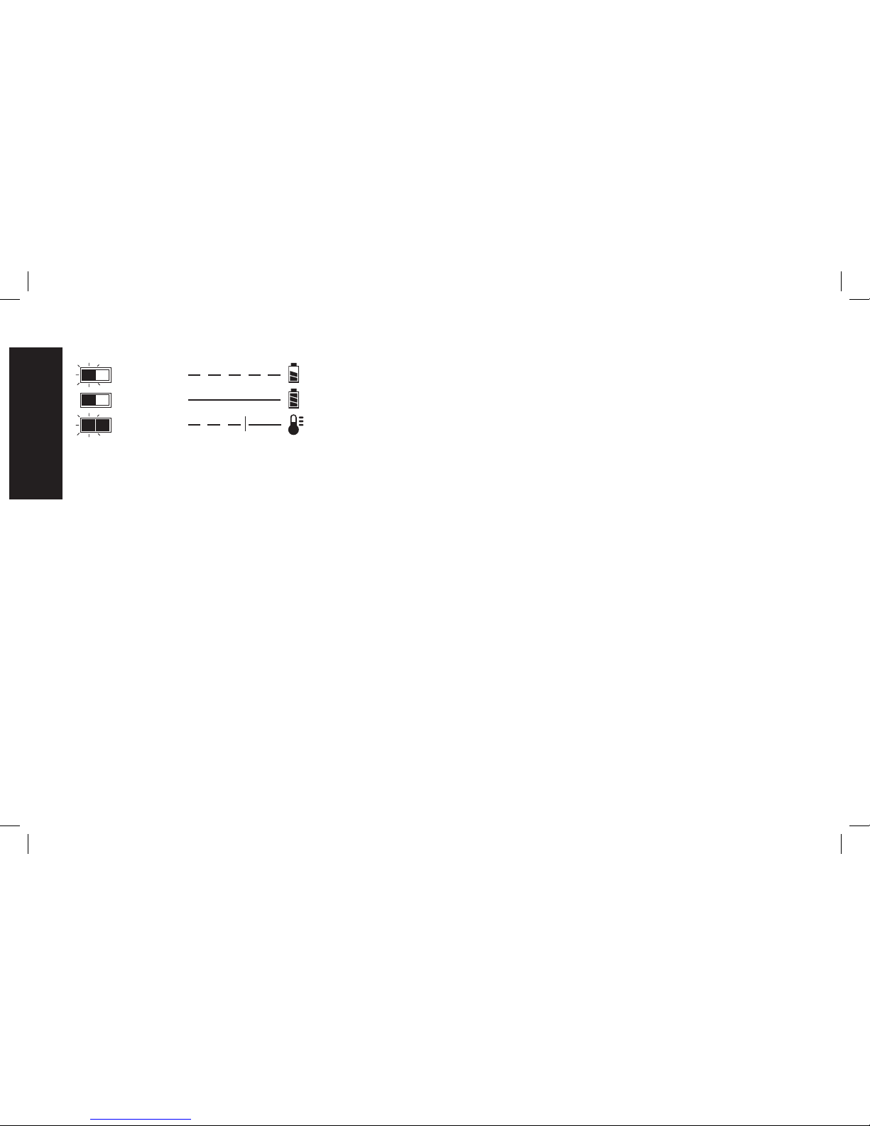
PACK CHARGING
PACK CHARGED
HOT/COLD DELAY
Charge Indicators
This charger is designed to detect certain problems that can arise.
Problems are indicated by the red light flashing at a fast rate. If this
occurs, re-insert the battery pack into the charger. If the problem
persists, try a different battery pack to determine if the charger is
working properly. If the new pack charges correctly, then the original
pack is defective and should be returned to a service center or other
collection site for recycling. If the new battery pack elicits the same
trouble indication as the original, have the charger and the battery
pack tested at an authorized service center.
HOT/COLD DELAY
DCB101, DCB102, DCB103
These chargers have a hot/cold delay feature. When the charger
detects a battery that is too hot or too cold, it automatically starts
a delay, suspending charging. The red light flashes long, then short
while in the hot/cold delay mode.
Once the battery has reached an optimum temperature, the charger
will automatically resume the charging procedure. This feature
ensures maximum battery life.
DCB107, DCB112, DCB113, DCB115
These chargers have a hot/cold delay feature. When the charger
detects a battery that is too hot or too cold, it automatically starts a
delay, suspending charging. The red light will continue to blink, but a
yellow indicator light will be illuminated during this suspension.
Once the battery has reached an optimum temperature, the yellow
light will turn off and the charger will automatically resume the
charging procedure. This feature ensures maximum battery life.
LEAVING THE BATTERY PACK IN THE CHARGER
The charger and battery pack can be left connected with the charge
indicator showing Pack Charged.
WEAK BATTERY PACKS: Weak batteries will continue to function
but should not be expected to perform as much work.
FAULTY BATTERY PACKS
DCB101, DCB102, DCB103
These chargers will not charge a faulty battery pack. The charger
will indicate faulty battery pack by refusing to light or by displaying
problem pack or charger.
NOTE: This could also mean a problem with a charger.
DCB107, DCB112, DCB113, DCB115
These chargers will not charge a faulty battery pack. The charger will
indicate faulty battery pack by refusing to light.
NOTE: This could also mean a problem with a charger.
Wall Mounting
DCB107, DCB112, DCB113, DCB115
These chargers are designed to be wall mountable or to sit upright on
a table or work surface.
If wall mounting, locate the charger within reach of an electrical
outlet. Mount the charger securely using drywall screws at least
1" (25.4 mm) long, screwed into wood to an optimal depth leaving
approximately 7/32" (5.5 mm) of the screw exposed.
Important Charging Notes
1. Longest life and best performance can be obtained if the battery
pack is charged when the air temperature is between 65°F and
English
8
Page 11

75 °F (18° – 24°C). DO NOT charge the battery pack in an air
temperature below +40°F (+4.5°C), or above +104°F (+40°C).
This is important and will prevent serious damage to the battery
pack.
2. The charger and battery pack may become warm to the touch
while charging. This is a normal condition, and does not indicate
a problem. To facilitate the cooling of the battery pack after use,
avoid placing the charger or battery pack in a warm environment
such as in a metal shed or an uninsulated trailer.
3. A cold battery pack will charge at about half the rate of a warm
battery pack. The battery pack will charge at that slower rate
throughout the entire charging cycle and will not return to
maximum charge rate even if the battery pack warms.
4. If the battery pack does not charge properly:
a. Check operation of receptacle by plugging in a lamp or other
appliance;
b. Check to see if receptacle is connected to a light switch which
turns power off when you turn out the lights;
c. Move the charger and battery pack to a location where the
surrounding air temperature is approximately 65 °F – 75 °F
(18° – 24°C);
d. If charging problems persist, take the tool, battery pack and
charger to your local service center.
5. The battery pack should be recharged when it fails to produce
sufficient power on jobs which were easily done previously. DO
NOT CONTINUE to use under these conditions. Follow the
charging procedure. You may also charge a partially used pack
whenever you desire with no adverse effect on the battery pack.
6. Foreign materials of a conductive nature such as, but not limited
to, grinding dust, metal chips, steel wool, aluminum foil, or any
buildup of metallic particles should be kept away from charger
cavities. Always unplug the charger from the power supply when
there is no battery pack in the cavity. Unplug the charger before
attempting to clean.
7. Do not freeze or immerse the charger in water or any other liquid.
WARNING: Shock hazard. Don’t allow any liquid to get inside the
charger. Electric shock may result.
WARNING: Burn hazard. Do not submerge the battery pack in
any liquid or allow any liquid to enter the battery pack. Never attempt
to open the battery pack for any reason. If the plastic housing of the
battery pack breaks or cracks, return to a service center for recycling.
Storage Recommendations
1. The best storage place is one that is cool and dry, away from
direct sunlight and excess heat or cold.
2. For long storage, it is recommended to store a fully charged
battery pack in a cool dry place out of the charger for optimal
results.
NOTE: Battery packs should not be stored completely depleted of
charge. The battery pack will need to be recharged before use.
SAVE THESE INSTRUCTIONS FOR
FUTURE USE
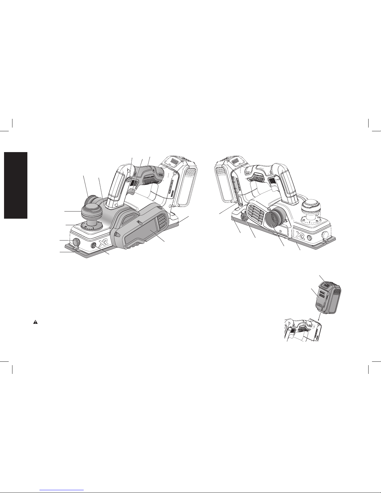
COMPONENTS (FIG. 2)
WARNING: Never modify the power tool or any part of it. Damage
or personal injury could result.
A. Trigger switch H. Rabbet fence tightening knob
B. Lock-off button I. Planing depth graduation
C. Main handle J. Planing depth adjustment knob/
D. Rear shoe front handle
E. Drive belt cover K. Chip discharge chute
F. Hole for rabbet fence L. Dust adapter
G. Front shoe M. Blade storage knob
English
9
Page 12
INTENDED USE
This planer is designed for professional planing applications of wood
and wood products.
DO NOT use under wet conditions or in presence of flammable
liquids or gases.
This planer is a professional power tool. DO NOT let children come
into contact with the tool. Supervision is required when inexperienced
operators use this tool.
OPERATION
WARNING: To reduce the risk of serious personal injury,
turn tool off and remove the battery pack before making any
adjustments or removing/installing attachments or accessories.
An accidental start-up can cause injury.
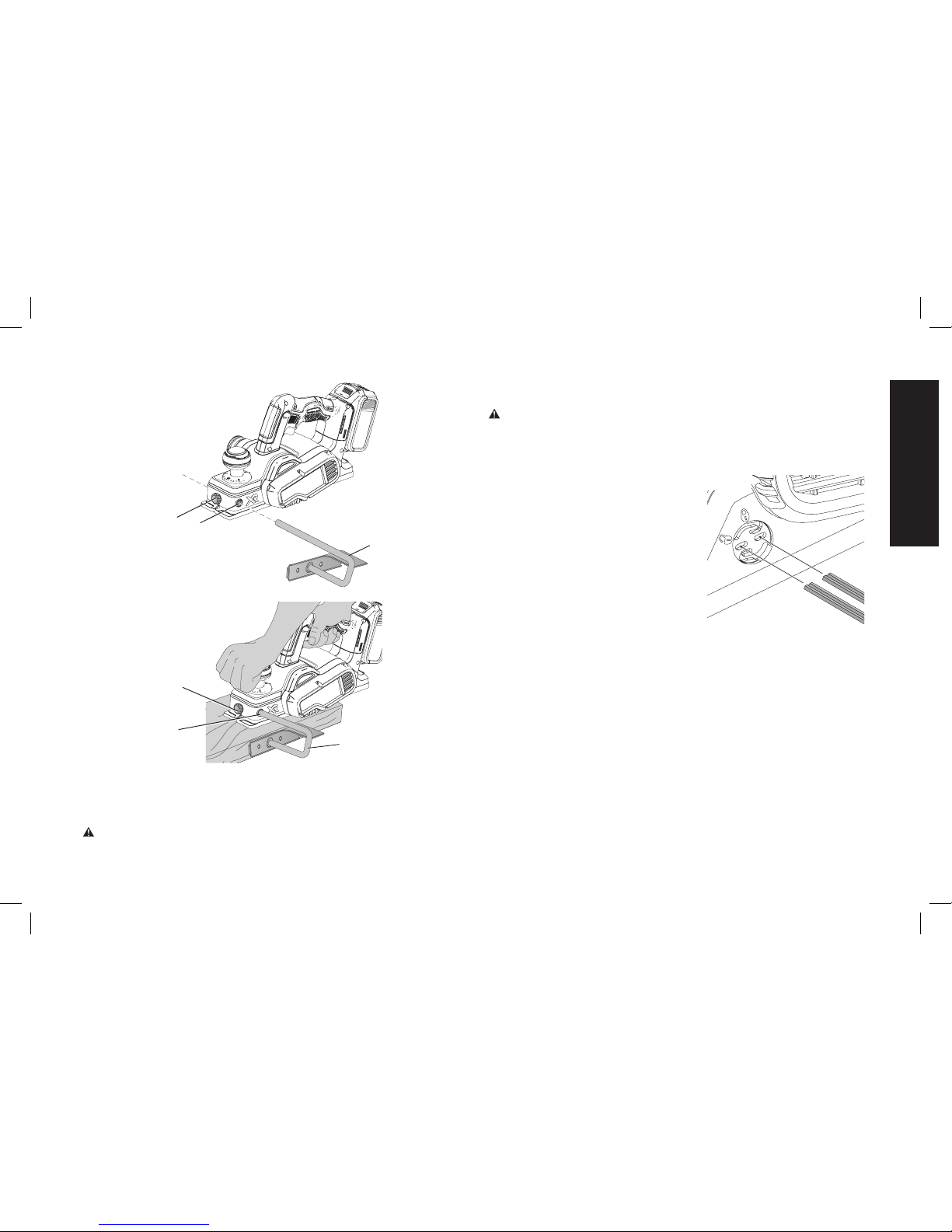
Installing and Removing the Battery Pack
(Fig. 3)
N
O
FIG. 3
NOTE: For best results, make sure
your battery pack is fully charged.
To install the battery pack (N) into the
tool handle, align the battery pack
with the rails inside the tool’s handle
and slide it into the handle until the
battery pack is firmly seated in the tool
and ensure that it does not disengage.
To remove the battery pack from the
tool, press the release button (O) and
firmly pull the battery pack out of the
FIG. 2
J
G
I
H
F
B
A
C
L
K
D
E
English
10
L
D
G
M
EE
Page 13
For more information regarding fuel gauge battery packs, please call
1-800-4-DeWALT (1-800-433-9258) or visit our website www.dewalt.
com.
P
FIG. 4
Trigger Switch (Fig. 2)
WARNING: This tool has no provision to lock the switch in the
ON position and should never be locked ON by any other means.
Release the trigger switch lock-off button (B) by pressing the button.
CAUTION: Allow the tool to reach full speed before touching tool
to the work surface. Lift the tool from the work surface before turning
the tool off.
To start the planer, depress the trigger switch (A).
To turn the planer off, release the trigger switch.
Adjusting the Planing Depth (Fig. 2)
To adjust the depth of cut, turn the planing depth adjustment knob (J).
Each click is equal to 0.1 mm of depth up to the maximum depth of
cut of approximately 5/64" (2.0 mm).
It is recom mended that test cuts be made in scrap wood after each
re-adjustment to make sure that the desired amount of wood is being
removed by the planer. Several shallow passes (rather than one deep
one) will produce a smoother finish.
tool handle. Insert it into the charger as described in the charger
section of this manual.
Squeeze the tool trigger for three seconds to dissipate the slight
electric charge that may still be in the tool. The worklight may come
on for a brief moment.
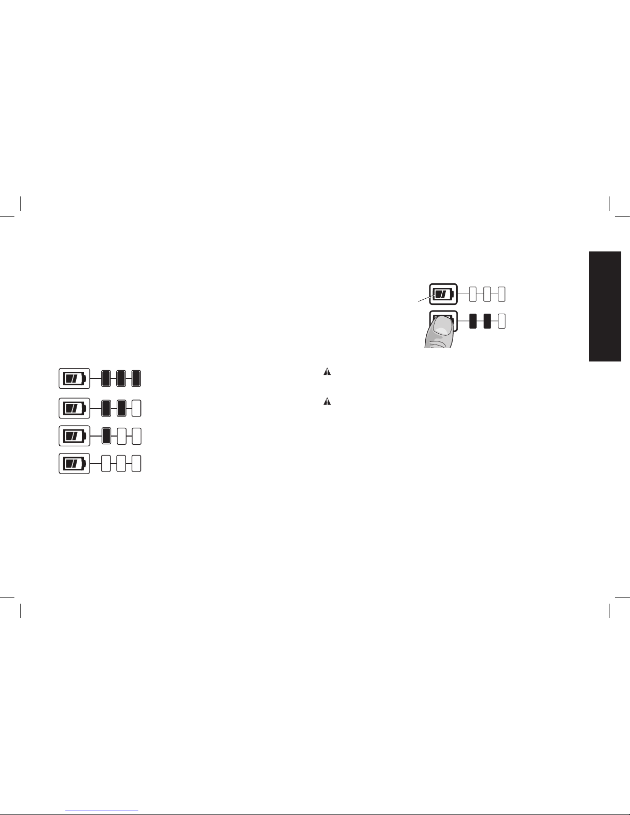
FUEL GAUGE BATTERY PACKS (FIG. 4)
Some DeWALT battery packs include a fuel gauge which consists of
three green LED lights that indicate the level of charge remaining in
the battery pack.
The fuel gauge is an indication of approximate levels of charge
remaining in the battery pack according to the following indicators:
75–100% charged
51–74% charged
< 50% charged
Pack needs to be charged
To actuate the fuel gauge, press and hold the fuel gauge button (P). A
combination of the three green LED lights will illuminate designating
the level of charge left. When the level of charge in the battery is below
the usable limit, the fuel gauge will not illuminate and the battery will
need to be recharged.
NOTE: The fuel gauge is only an indication of the charge left on the
battery pack. It does not indicate tool functionality and is subject to
variation based on product components, temperature and end-user
application.
English
11
Page 14
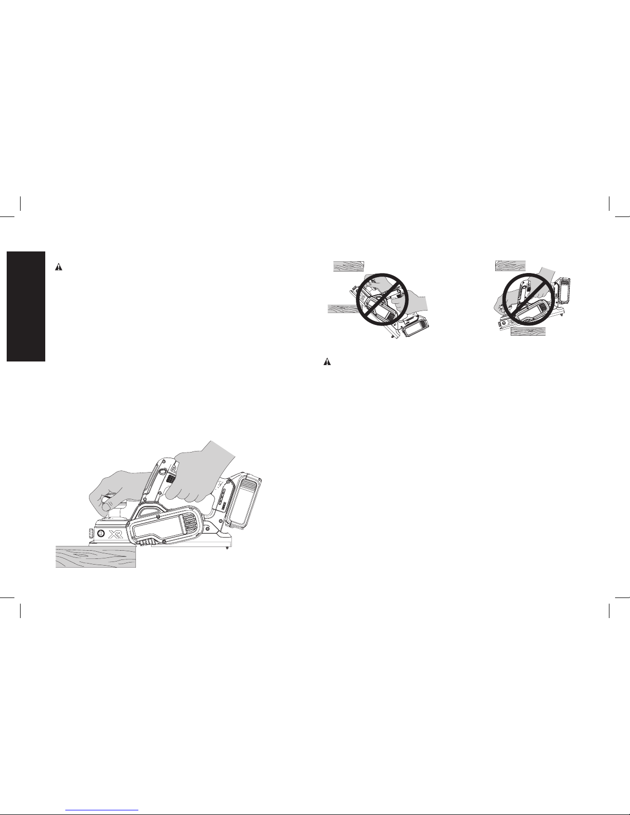
Planing (Fig. 2, 5–7)
CAUTION: Allow the tool to reach full speed before touching tool
to the work surface. Lift the tool from the work surface before turning
the tool off.
Hold the planer in the correct position with one hand on the front
handle (J) and the other hand on the main handle (C) as shown in
Figure 2. Place the front shoe (G) on the surface to be planed, making
certain that the cutting blades are not touching the surface. Push
down firmly on the front handle of the planer so that the front shoe is
ABSOLUTELY FLAT on the work surface. Squeeze the trigger switch
and allow the motor to reach full speed before touching the planer
blades to the work surface.
Move the tool slowly into the work and maintain downward pressure
to keep the planer flat. Be particularly careful to keep the tool flat at
the beginning and the end of the work surface.
Planing Tip: For a smoother appearance, fasten a piece of scrap
wood to the end of the piece you are planing. Don’t stop planing until
the cutting blades of the planer are past your workpiece and into the
scrap material.
FIG. 5
CORRECT
FIG. 6
FIG. 7
INCORRECT
Rabbet Fence (Fig. 8, 9)
WARNING: Allow the tool to reach full speed before touching tool
to the work surface. Lift the tool from the work surface before turning
the tool off.
The rabbet fence (Q) is used for optimum tool control on narrow
workpieces and can be installed on either side of your planer. The
planer makes rabbet cuts up to 23/64" (9 mm).
TO INSTALL RABBET FENCE
1. Loosen the rabbet fence tightening knob (H).
2. Slide the crossbar on the rabbet fence (Q) into the hole (F) on the
side of the planer as shown in Figure 8.
3. Set the width of cut by adjusting the edge guide across the width
of the shoe.
4. Securely tighten rabbet fence tightening knob (H).
NOTE: The rabbet fence should be below the planer when installed
correctly as shown in Figure 9.
TO MAKE A RABBET CUT
1. Turn the rabbet fence tightening knob (H) to adjust the desired
width of cut.
2. Make several cuts until the desired depth is reached.
English
12
Page 15
NOTE: It will be necessary to make quite a few cuts for most rabbet
applications.
To Change Blades (Fig. 10, 11)
WARNING: To reduce the risk of serious personal injury,
turn tool off and remove the battery pack before making any
adjustments or removing/installing attachments or accessories.
An accidental start-up can cause injury.
CAUTION: Planer blades are extremely sharp. Handle with great
care.
The planer is capable of using high-speed steel and carbide blades.
Be sure to check the planer to verify which blade it is fitted with.
BLADE STORAGE (FIG. 10)
FIG. 10
Your planer is equipped with blade
storage for two additional blades. To
store or remove additional blades,
turn the blade storage knob (M)
counter clockwise to open.
HIGH-SPEED STEEL BLADES
(FIG. 11)
1. To Remove Blade from Planer
(Fig. 11B)
a. Loosen and remove the three
star head screws (R) with the
T25 star head key (EE) provided. Remove the drum cover (S)
from the drum (T).
b. Remove the guide bar/high-speed steel blade assembly (U, V,
W).
2. To Adjust Blade Using Gauge Plate (provided with tool) (Fig. 11C)
a. Place the guide bar/high-speed steel blade assembly on the
gauge plate (X) with the cutting edge of the high-speed steel
blade flush against the gauge plate inside wall (Y). The heel of
the guide bar (W) will overlap the end of the gauge plate (X).
b. Loosen the two cross-shaped screws (V) with a screwdriver.
c. Simultaneously hold the blade edge (U) against the gauge
plate inside wall (Y) and the heel of the guide bar (W) against
the back edge of the gauge plate. Securely tighten the cross
shaped screws (V).
FIG. 9
H
F
Q
H
FIG. 8
F
Q
English
13
Page 16
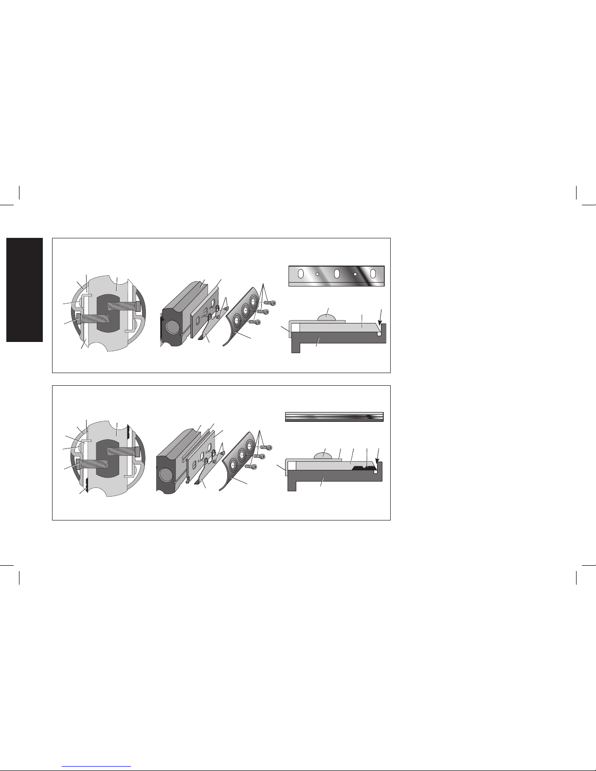
HIGH-SPEED STEEL BLADE
U
S
R
W
V
T
U
R
S
W
V
T
FIG. 11A FIG. 11B FIG. 11C
FIG. 11
U
Y
W
X
V
CARBIDE BLADE
FIG. 12A
Z
R
S
AA
W
V
T
Z
S
R
W
AA
V
T
FIG. 12B FIG. 12C
FIG. 12
AA Z
Y
W
X
V
3. To Reinstall Blade (Fig. 10A, 10B)
a. Cautiously remove the adjusted
guide bar/high-speed steel blade
assembly from the gauge plate (X)
and place the heel of the guide bar
(W) into the groove in the drum (T).
b. Set the drum cover (S) over the
adjusted guide bar/high-speed
steel blade assembly and securely
tighten the three star head screws
(R) to the drum.
4. Repeat procedure for the other blade.
NOTE: In order to use high-speed steel
blades with this planer, the sharpening
holder (BB) is required to sharpen highspeed steel blades and is available at
additional cost from your local DeWA LT
authorized service center.
REVERSIBLE CARBIDE BLADES
(FIG.12)
1. To Remove Blade from Planer
(Fig.12B)
a. Loosen and remove the three star
head screws (R) with the T25 star
key (EE) provided. Remove the
drum cover (S) from the drum (T).
b. Remove the blade carrier/guide bar
assembly (V, W, Z). Carefully remove
the carbide blade (Z).
2. To Adjust Blade Using Gauge Plate
(provided with tool) (Fig. 12C)
a. Cautiously place the sharp edge of
the carbide blade (Z) on the gauge
W
English
14
Page 17
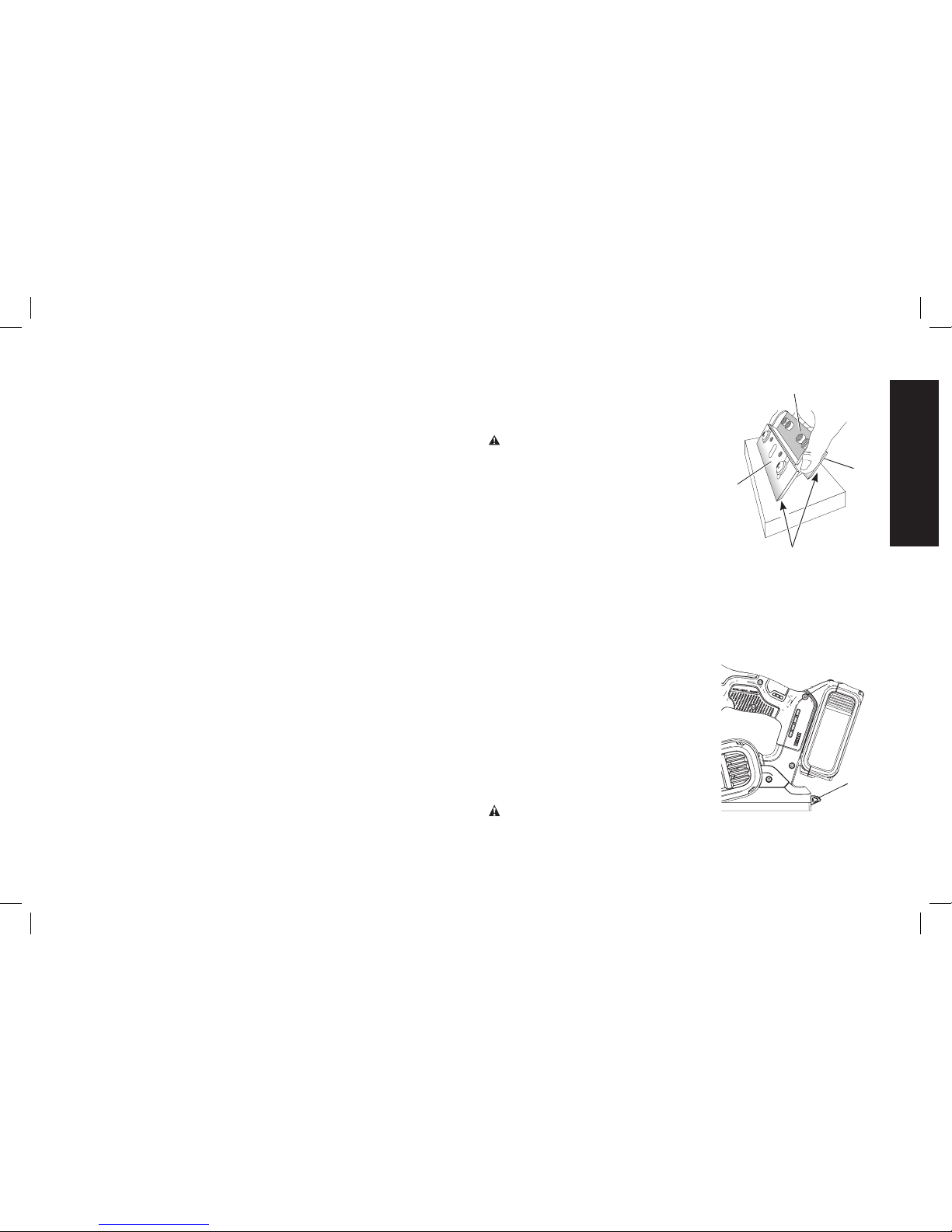
plate (X) with the grooved side of the carbide blade facing up.
Either edge of the reversible carbide blade can be set flush
against the gauge plate inside wall (Y).
b. Place the blade carrier/guide bar assembly on the blade so
that the rib on the blade carrier (AA) fits into the groove on the
carbide blade (Z). The heel of the guide bar (W) will over-hang
the end of the gauge plate (X).
c. Loosen the two cross-shaped screws (V) with a screwdriver.
d. Simultaneously hold the blade carrier (AA) and blade (Z)
against the gauge plate inside wall (Y) while holding the heel
of the guide bar (W) against the back edge of the gauge plate.
Securely tighten the cross shaped screws (V).
3. To Replace the Blade (Fig. 12A, 12B)
a. Remove the adjusted blade carrier/guide bar assembly from
the gauge plate (X) and place the heel of the guide bar (W) into
the groove on the drum (T).
b. Place the drum cover (S) over the blade carrier/guide bar
assembly. Loosely screw the three star head screws (R) into
the drum (T) so that there is a small gap between the drum
and the blade carrier (AA).
c. Slide the carbide blade between the drum (T) and the blade
carrier (AA) from the side so that the rib on the blade carrier
sets into the groove in the blade.
d. Center the carbide blade (Z) under the blade carrier (AA)
making sure the blade is clear of the tool housing on both
sides.
e. Securely tighten the three star head screws (R) to the drum.
4. Repeat procedure for the other blade.
NOTE: If your planer is not fitted with carbide blades, the blade
carrier (AA) required for carbide blades is available at additional cost
from your local DeWALT authorized service center.
Sharpening High-
BB
FIG. 13
U
BLADE EDGE
U
Speed Steel Blades
(Fig.13)
CAUTION: Planer blades are
extremely sharp. Handle with great
care.
NOTE: Carbide blades cannot be
sharpened.
1. Fasten the blades to the
sharpening holder (BB). Make
sure both blade edges (U) are
facing the same direction.
2. Place the blade edges so they
rest flat on the grinding stone (not
included).
3. Firmly grip the sharpening holder and move it back and forward
to sharpen the blades (U).
Kickstand (Fig. 14)
FIG. 14
CC
Your planer is equipped with a kickstand
(CC) that automatically lowers when
the tool is lifted from the work surface
allowing the planer to set on the work
surface without the blade touching it.
When planing, the kickstand raises as
the tool is pushed forward through
the material. If the kickstand obstructs
special planing work, it can be stored
and locked out of the way.
CAUTION: Be sure that the kickstand
is correctly extended when setting the planer on a work surface.
English
15
Page 18
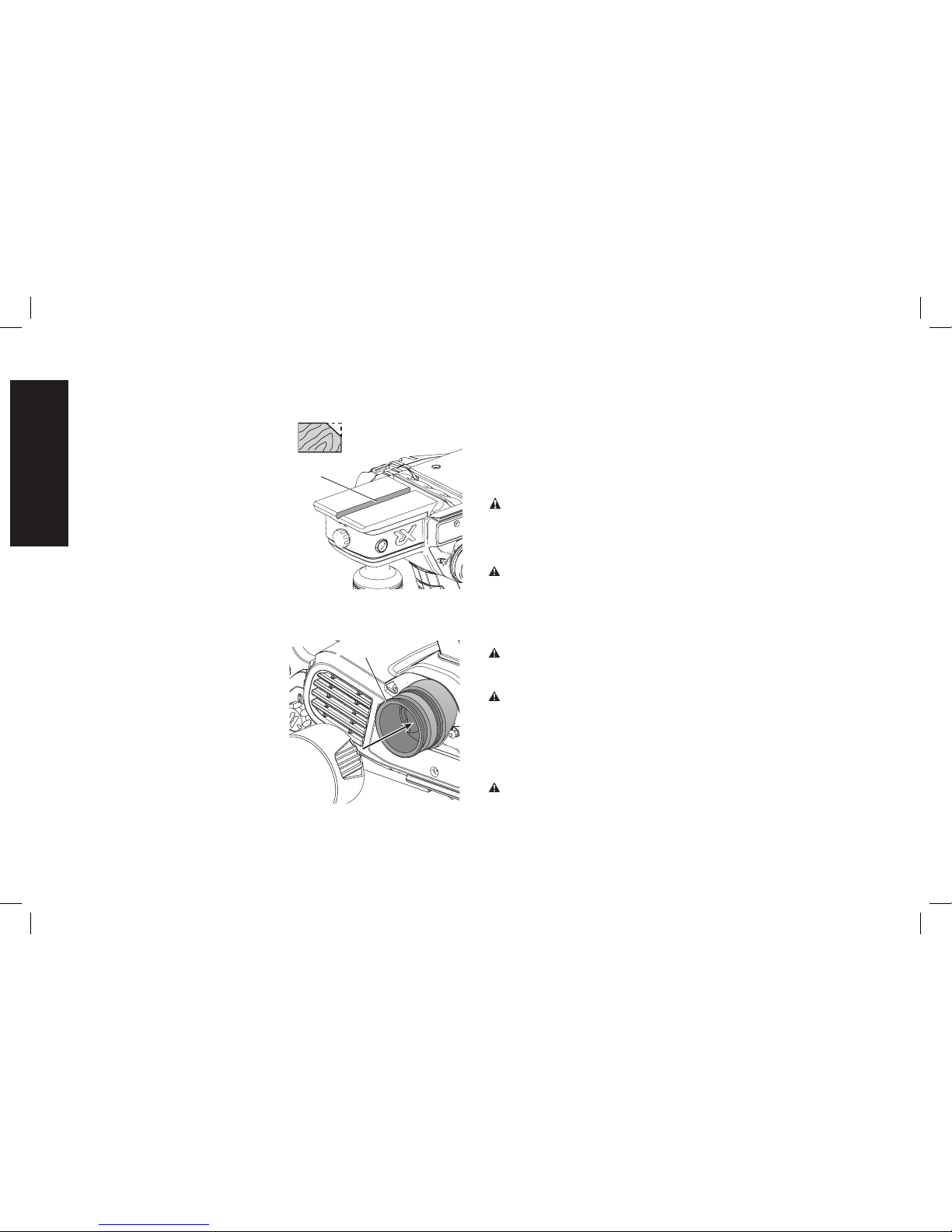
Edge Chamfering (Fig. 15)
Your planer has a precision machined
FIG. 15
DD
chamfering groove (DD) in the front
shoe for planing along a corner of
the wood. The width of the groove
is 4.5 to 8 mm. It’s a good idea to
try a piece of scrap wood before
doing finish work.
Dust Extraction
(Fig.2, 16)
Your planer has a built-in dust
extraction port (L) which allows either
a dust bag or a shop vacuum to be
connected. The built-in outlet utilizes
the DeWALT AirLock connection
system making it compatible with the DeWALT dust extractor.
TO ATTACH THE DUST BAG
FIG. 16
L
While holding the planer, slide
the dust bag collar onto the dust
extraction port (L) as shown in
Figure16.
TO EMPTY THE DUST BAG
1. While holding the planer,
remove the dust bag by sliding
it off the dust extraction port (L).
2. Gently shake or tap the dust
bag to empty.
3. Reattach the dust bag back
onto the outlet.
You may notice that all the dust will not come free from the bag. This
will not affect planing performance but will reduce the planer’s dust
collection efficiency. To restore your planer’s dust collection efficiency,
depress the spring inside the dust bag when you are emptying it and
tap it on the side of the trash can or dust receptacle.
NOTE: A DeWALT AirLock Adapter (DWV9000) can be purchased
separately to connect a shop vacuum or DeWALT dust extractor to
your planer.
CAUTION: Never operate these tools unless the dust
collector is in place. Planing dust exhaust may create a breathing
hazard.
MAINTENANCE
WARNING: To reduce the risk of serious personal injury,
turn tool off and remove the battery pack before making any
adjustments or removing/installing attachments or accessories.
An accidental start-up can cause injury.
Cleaning
WARNING: Blow dirt and dust out of all air vents with clean, dry air
at least once a week. To minimize the risk of eye injury, always wear
ANSI Z87.1 approved eye protection when performing this.
WARNING: Never use solvents or other harsh chemicals for
cleaning the non-metallic parts of the tool. These chemicals may
weaken the plastic materials used in these parts. Use a cloth
dampened only with water and mild soap. Never let any liquid get
inside the tool; never immerse any part of the tool into a liquid.
CHARGER CLEANING INSTRUCTIONS
WARNING: Shock hazard. Disconnect the charger from the AC
outlet before cleaning. Dirt and grease may be removed from the
exterior of the charger using a cloth or soft non-metallic brush. Do not
use water or any cleaning solutions.
English
16
Page 19

CHIP DISCHARGE CHUTE CLEANING INSTRUCTIONS
If the unit is clogged with dust or chips, use a non-metallic stick to
push the obstruction out of the chip discharge chute (K). Never stick
your finger into the chute.
Accessories
WARNING: Since accessories, other than those offered by
DeWALT, have not been tested with this product, use of such
accessories with this tool could be hazardous. To reduce the risk of
injury, only DeWALT recommended accessories should be used with
this product.
Recommended accessories for use with your tool are available at
extra cost from your local dealer or authorized service center. If you
need assistance in locating any accessory, please contact DeWALT
Industrial Tool Co., 701 East Joppa Road, Towson, MD 21286, call
1-800-4-DeWALT (1-800-433-9258) or visit our website: www.dewalt.
com.
Repairs
The charger and battery pack are not serviceable.
To assure product SAFETY and RELIABILITY, repairs, maintenance
and adjustment should be performed by a DeWA LT factory service
center, a DeWALT authorized service center or other qualified service
personnel. Always use identical replacement parts.
Register Online
Thank you for your purchase. Register your product now for:
• WARRANTY SERVICE: Registering your product will help you
obtain more efficient warranty service in case there is a problem
with your product.
• CONFIRMATION OF OWNERSHIP: In case of an insurance
loss, such as fire, flood or theft, your registration of ownership will
serve as your proof of purchase.
Three Year Limited Warranty
DeWA LT will repair, without charge, any defects due to faulty materials
or workmanship for three years from the date of purchase. This
warranty does not cover part failure due to normal wear or tool
abuse. For further detail of warranty coverage and warranty repair
information, visit www.dewalt.com or call 1-800-4-DeWALT (1-800-
433-9258). This warranty does not apply to accessories or damage
caused where repairs have been made or attempted by others. This
warranty gives you specific legal rights and you may have other rights
which vary in certain states or provinces.
In addition to the warranty, DeWALT tools are covered by our:
1 YEAR FREE SERVICE
DeWA LT will maintain the tool and replace worn parts caused by
normal use, for free, any time during the first year after purchase.
2 YEARS FREE SERVICE ON DeWALT BATTERY PACKS
DC9071, DC9091, DC9096, DC9280, DC9360, DC9180,
DCB120, DCB127, DCB201, DCB203, DCB203BT, DCB207
3 YEARS FREE SERVICE ON DeWALT BATTERY PACKS
DCB200, DCB204, DCB204BT, DCB205
DeWALT BATTERY PACKS
Product warranty voided if the battery pack is tampered with in any
way. DeWA LT is not responsible for any injury caused by tampering
and may prosecute warranty fraud to the fullest extent permitted by
law.
90 DAY MONEY BACK GUARANTEE
If you are not completely satisfied with the performance of your
DeWA LT Power Tool, Laser, or Nailer for any reason, you can return
it within 90 days from the date of purchase with a receipt for a full
refund – no questions asked.
English
17
Page 20
LATIN AMERICA: This warranty does not apply to products sold
in Latin America. For products sold in Latin America, see country
specific warranty information contained in the packaging, call the
local company or see website for warranty information.
FREE WARNING LABEL REPLACEMENT: If your warning labels
become illegible or are missing, call 1-800-4-DeWALT (1-800-433-
9258) for a free replacement.
English
18
Page 21

Définitions : lignes directrices
enmatière de sécurité
Les définitions ci-dessous décrivent le niveau de danger pour
chaque mot-indicateur employé. Lire le mode d’emploi et porter
une attention particulière à ces symboles.
DANGER: indique une situation dangereuse imminente qui,
si elle n’est pas évitée, entraînera la mort ou des blessures
graves.
AVERTISSEMENT : indique une situation potentiellement
dangereuse qui, si elle n’est pas évitée, pourrait entraîner la mort
ou des blessures graves.
ATTENTION: indique une situation potentiellement dangereuse
qui, si elle n’est pas évitée, pourrait entraîner des blessures
légères ou modérées.
AVIS : indique une pratique ne posant aucun risque de
dommages corporels mais qui par contre, si rien n’est fait pour
l’éviter, pourrait poser des risques de dommages matériels.
POUR TOUTE QUESTION OU REMARQUE AU SUJET DE CET
OUTIL OU DE TOUT AUTRE OUTIL DeWALT, COMPOSEZ LE
NUMÉRO SANS FRAIS: +1-800-4-DeWALT (+1800433-9258).
AVERTISSEMENT: afin de réduire le risque de blessures, lire
le mode d’emploi de l’outil.
Avertissements de sécurité généraux
pour les outils électriques
AVERTISSEMENT! Lire tous les avertissements de
sécurité et toutes les Directives. Le non-respect des
avertissements et des directives pourrait se solder par un choc
électrique, un incendie et/ou une blessure grave.
CONSERVER TOUS LES AVERTISSEMENTS
ET TOUTES LES DIRECTIVES POUR UN
USAGE ULTÉRIEUR
Le terme «outil électrique» cité dans les avertissements se rapporte
à votre outil électrique à alimentation sur secteur (avec fil) ou à piles
(sans fil).
1) SÉCURITÉ DU LIEU DE TRAVAIL
a) Tenir l’aire de travail propre et bien éclairée. Les lieux
encombrés ou sombres sont propices aux accidents.
b) Ne pas faire fonctionner d’outils électriques dans un
milieu déflagrant, tel qu’en présence de liquides, de
gaz ou de poussières inflammables. Les outils électriques
produisent des étincelles qui pourraient enflammer la poussière
ou les vapeurs.
c) Éloigner les enfants et les personnes à proximité pendant
l’utilisation d’un outil électrique. Une distraction pourrait en
faire perdre la maîtrise à l’utilisateur.
2) SÉCURITÉ EN MATIÈRE D’ÉLECTRICITÉ
a) Les fiches des outils électriques doivent correspondre
à la prise. Ne jamais modifier la fiche d’aucune façon.
Ne jamais utiliser de fiche d’adaptation avec un outil
électrique mis à la terre. Le risque de choc électrique sera
réduit par l’utilisation de fiches non modifiées correspondant à
la prise.
b) Éviter tout contact physique avec des surfaces mises
à la terre comme des tuyaux, des radiateurs, des
cuisinières et des réfrigérateurs. Le risque de décharge
électrique est plus élevé si votre corps est mis à la terre.
c) Ne pas exposer les outils électriques à la pluie ou à
l'humidité. La pénétration de l’eau dans un outil électrique
augmente le risque de choc électrique.
Français
19
Page 22

d) Ne pas utiliser le cordon de façon abusive. Ne jamais
utiliser le cordon pour transporter, tirer ou débrancher
un outil électrique. Tenir le cordon éloigné de la chaleur,
de l’huile, des bords tranchants et des pièces mobiles.
Les cordons d'alimentation endommagés ou enchevêtrés
augmentent le risque de décharge électrique.
e) Pour l’utilisation d’un outil électrique à l’extérieur, se
servir d’une rallonge convenant à cette application.
L’utilisation d’une rallonge conçue pour l’extérieur réduira les
risques de décharge électrique.
f) S'il est impossible d'éviter l’utilisation d’un outil
électrique dans un endroit humide, brancher l’outil dans
une prise ou sur un circuit d’alimentation dotés d’un
disjoncteur de fuite à la terre (GFCI). L'utilisation de ce type
de disjoncteur réduit les risques de choc électrique.
3) SÉCURITÉ PERSONNELLE
a) Être vigilant, surveiller le travail effectué et faire preuve
de jugement lorsqu’un outil électrique est utilisé. Ne
pas utiliser d’outil électrique en cas de fatigue ou sous
l’influence de drogues, d’alcool ou de médicaments. Un
simple moment d’inattention en utilisant un outil électrique peut
entraîner des blessures corporelles graves.
b) Utiliser des équipements de protection individuelle.
Toujours porter une protection oculaire. L’utilisation
d’équipements de protection comme un masque antipoussière,
des chaussures antidérapantes, un casque de sécurité ou des
protecteurs auditifs lorsque la situation le requiert réduira les
risques de blessures corporelles.
c) Empêcher les démarrages intempestifs. S’assurer que
l’interrupteur se trouve à la position d’arrêt avant de
relier l’outil à une source d’alimentation et/ou d’insérer
un bloc-piles, de ramasser ou de transporter l’outil.
Transporter un outil électrique alors que le doigt repose sur
l’interrupteur ou brancher un outil électrique dont l’interrupteur
est à la position de marche risque de provoquer un accident.
d) Retirer toute clé de réglage ou clé avant de mettre
l'outil électrique en marche. Une clé ou une clé de réglage
attachée à une partie pivotante de l’outil électrique peut
provoquer des blessures corporelles.
e) Ne pas trop tendre les bras. Conserver son équilibre en
tout temps. Cela permet de mieux maîtriser l’outil électrique
dans les situations imprévues.
f) S’habiller de manière appropriée. Ne pas porter de
vêtements amples ni de bijoux. Garder les cheveux, les
vêtements et les gants à l’écart des pièces mobiles. Les
vêtements amples, les bijoux ou les cheveux longs risquent de
rester coincés dans les pièces mobiles.
g) Si des composants sont fournis pour le raccordement de
dispositifs de dépoussiérage et de ramassage, s’assurer
que ceux-ci sont bien raccordés et utilisés. L’utilisation
d’un dispositif de dépoussiérage peut réduire les dangers
engendrés par les poussières.
4) UTILISATION ET ENTRETIEN D’UN OUTIL ÉLECTRIQUE
a) Ne pas forcer un outil électrique. Utiliser l’outil électrique
approprié à l’application. L’outil électrique approprié
effectuera un meilleur travail, de façon plus sûre et à la vitesse
pour laquelle il a été conçu.
b) Ne pas utiliser un outil électrique dont l’interrupteur
est défectueux. Tout outil électrique dont l’interrupteur est
défectueux est dangereux et doit être réparé.
c) Débrancher la fiche de la source d’alimentation et/ou du
bloc-piles de l’outil électrique avant de faire tout réglage
ou changement d’accessoire ou avant de ranger l’outil.
Ces mesures préventives réduisent les risques de démarrage
accidentel de l’outil électrique.
Français
20
Page 23

d) Ranger les outils électriques hors de la portée des
enfants et ne permettre à aucune personne n’étant
pas familière avec un outil électrique ou son mode
d’emploi d’utiliser cet outil. Les outils électriques deviennent
dangereux entre les mains d’utilisateurs inexpérimentés.
e) Entretien des outils électriques. Vérifier si les pièces
mobiles sont mal alignées ou coincées, si des pièces sont
brisées ou présentent toute autre condition susceptible
de nuire au bon fonctionnement de l’outil électrique.
En cas de dommage, faire réparer l’outil électrique
avant toute nouvelle utilisation. Beaucoup d’accidents sont
causés par des outils électriques mal entretenus.
f) S’assurer que les outils de coupe sont aiguisés et
propres. Les outils de coupe bien entretenus et affûtés sont
moins susceptibles de se coincer et sont plus faciles à maîtriser.
g) Utiliser l’outil électrique, les accessoires, les forets,
etc. conformément aux présentes directives en tenant
compte des conditions de travail et du travail à effectuer.
L’utilisation d’un outil électrique pour toute opération autre que
celle pour laquelle il a été conçu est dangereuse.
5) UTILISATION ET ENTRETIEN DU BLOC-PILES
a) Ne recharger l’outil qu’au moyen du chargeur précisé
par le fabricant. L’utilisation d’un chargeur qui convient à
un type de bloc-piles risque de provoquer un incendie s’il est
utilisé avec un autre type de bloc-piles.
b) Utiliser les outils électriques uniquement avec les blocs-
piles conçus à cet effet. L’utilisation de tout autre bloc-piles
risque de causer des blessures ou un incendie.
c) Lorsque le bloc-piles n’est pas utilisé, le tenir éloigné
des objets métalliques, notamment des trombones, de
la monnaie, des clés, des clous, des vis ou autres petits
objets métalliques qui peuvent établir une connexion
entre les deux bornes. Le court-circuit des bornes du bloc-
piles risque de provoquer des brûlures ou un incendie.
d) En cas d’utilisation abusive, le liquide peut gicler hors
du bloc-piles; éviter tout contact avec ce liquide. Si
un contact accidentel se produit, laver à grande eau.
Si le liquide entre en contact avec les yeux, obtenir
également des soins médicaux. Le liquide qui gicle hors du
bloc-piles peut provoquer des irritations ou des brûlures.
6) RÉPARATION
a) Faire réparer l’outil électrique par un réparateur
professionnel en n’utilisant que des pièces de rechange
identiques. Cela permettra de maintenir une utilisation
sécuritaire de l’outil électrique.
Consignes additionnelles de sécurité
propres aux raboteuses
• Attendre l’arrêt complet de l’organe de coupe avant de
poser l’outil sur une surface quelconque. Un organe de
coupe en rotation à nu pourrait attaquer la surface et causer la
perte de contrôle de l’outil et des dommages corporels graves.
• Tenir l’outil électrique uniquement par ses surfaces de prise
isolées. L’organe de coupe pourrait entrer en contact avec
des fils cachés. Couper un fil sous tension pourra mettre les
parties métalliques exposées de l’outil sous tension et électrocuter
l’utilisateur.
• Utiliser des serre-joints, ou tout autre moyen, pour fixer et
immobiliser le matériau sur une surface stable. Tenir la pièce
à la main ou contre son corps offre une stabilité insuffisante qui
pourrait vous en faire perdre le contrôle.
• S’assurer de bien mettre l’interrupteur en position d’arrêt avant de
retirer ou d’installer le bloc-piles.
Français
21
Page 24

• S’assurer de mettre immédiatement l’interrupteur en position
d’ARRÊT si l’outil s’enraye.
• S’assurer que l’outil est réglé à la bonne profondeur avant de le
mettre en MARCHE.
• S’assurer d’effectuer une bonne maintenance de l’outil. Suivre
toute instruction relative à la lubrification et au changement
d’accessoire.
• S’assurer que l’organe de coupe a bien été monté suivant les
instructions du manuel, et que toutes les vis sur l’outil sont bien
serrées avant d’installer le bloc-piles.
• Maintenir tout évent libre de toute obstruction pour assurer le
refroidissement correct du moteur.
• NE PAS poser l’outil sur son patin lorsque ses lames sont à nu.
Ces dernières pourraient subir des dommages.
• Maintenir systématiquement tout orifice latéral d’éjection libre de
toute obstruction.
• Ne jamais passer sa main sous l’outil à moins qu’il ne soit à l’arrêt
et que son BLOC-PILES AIT ÉTÉ RETIRÉ. LES LAMES SONT À
NU ET EXTRÊMEMENT COUPANTES.
• N’utiliser cet outil que pour travailler le bois ou tout produit du bois.
• S’assurer systématiquement que la surface de travail ne comporte
ni clou ni objets étrangers.
• Utiliser systématiquement la raboteuse à deux mains. Ne jamais
utiliser l’outil sans tenir fermement sa poignée avant.
• L’organe de coupe de la raboteuse est extrêmement acéré. Utiliser
la raboteuse avec la plus grande vigilance.
• Nettoyer votre outil souvent, surtout après un usage intensif.
• Prendre des précautions à proximité des évents, car ils
cachent des pièces mobiles. Vêtements amples, bijoux ou
cheveux longs risquent de rester coincés dans ces pièces mobiles.
AVERTISSEMENT: porter SYSTEMATIQUEMENT des lunettes
de protection. Les lunettes courantes NE sont PAS des lunettes de
protection. Utiliser aussi un masque antipoussières si la découpe
doit en produire beaucoup. PORTER SYSTÉMATIQUEMENT UN
ÉQUIPEMENT DE SÉCURITÉ HOMOLOGUÉ.
• Protection oculaire ANSI Z87.1 (CAN/CSA Z94.3),
• Protection auditive ANSI S12.6 (S3.19),
• Protection des voies respiratoires NIOSH/OSHA/MSHA.
AVERTISSEMENT : les scies, meules, ponceuses, perceuses
ou autres outils de construction peuvent produire des poussières
contenant des produits chimiques reconnus par l’État californien
pour causer cancers, malformations congénitales ou être nocifs au
système reproducteur. Voici quelques exemples de ces produits
chimiques:
• Le plomb dans les peintures à base de plomb,
• La silice cristallisée dans les briques et le ciment, ou autres
produits de maçonnerie, et
• L’arsenic et le chrome dans le bois ayant subi un traitement
chimique.
Le risque associé à de telles expositions varie selon la fréquence à
laquelle on effectue ces travaux. Pour réduire toute exposition à ces
produits: travailler dans un endroit bien aéré, en utilisant du matériel
de sécurité homologué, tel un masque antipoussières spécialement
conçu pour filtrer les particules microscopiques.
• Limiter toute exposition prolongée avec les poussières
provenant du ponçage, sciage, meulage, perçage ou toute
autre activité de construction. Porter des vêtements de
protection et nettoyer à l’eau savonneuse les parties du
corps exposées. Le fait de laisser la poussière pénétrer dans la
bouche, les yeux ou la peau peut favoriser l’absorption de produits
chimiques dangereux.
Français
22
Page 25

AVERTISSEMENT : cet outil peut produire et/ou répandre
de la poussière susceptible de causer des dommages sérieux et
permanents au système respiratoire. Utiliser systématiquement un
appareil de protection des voies respiratoires homologué par le
NIOSH ou l’OSHA. Diriger les particules dans le sens opposé au
visage et au corps.
AVERTISSEMENT : pendant l’utilisation, porter
systématiquement une protection auditive individuelle
adéquate homologuée ANSI S12.6 (S3.19). Sous certaines
conditions et suivant la durée d’utilisation, le bruit émanant de ce
produit pourrait contribuer à une perte de l’acuité auditive.
ATTENTION : après utilisation, ranger l’outil sur son côté,
sur une surface stable, là où il ne pourra ni faire trébucher
ni faire chuter quelqu’un. Certains outils équipés d’un large
bloc-piles peuvent tenir à la verticale sur celui-ci, mais manquent
alors de stabilité.
• L’étiquette apposée sur votre outil peut inclure les symboles
suivants. Les symboles et leur définition sont indiqués ci-après:
V ................... volts A ....................... ampères
Hz ................. hertz W ...................... watts
min ............... minutes ou AC .......... courant alternatif
ou DC ... courant continu ou AC/DC ... courant alternatif
................. classe I fabrication ....................... ou continu
..................... (mis à la terre) no ..................... vitesse à vide
................. fabrication n .......................vitesse nominale
..................... classe II (double ......................borne de terre
..................... isolation) ...................... symbole
…/min ........... par minute .........................d’avertissement
IPM ............... impacts par SPM (FPM) ....... fréquence par
..................... minute .........................minute
BPM ............. battements par r/min ................. tours par
..................... minute .........................minute
sfpm ............. pieds linéaires ..................... rayonnement
..................... par minute (plpm) ......................... visible
Consignes importantes de sécurité
propres à tous les blocs-piles
Pour commander un bloc-piles de rechange, s’assurer d’inclure son
numéro de catalogue et sa tension. Consulter le tableau en dernière
page de ce manuel pour connaître les compatibilités entre chargeurs
et blocs-piles.
Le bloc-piles n’est pas totalement chargé d’usine. Avant d’utiliser le
bloc-piles et le chargeur, lire les consignes de sécurité ci-dessous.
LIRE TOUTES LES CONSIGNES
• Ne pas recharger ou utiliser un bloc-piles en milieu
déflagrant, en présence, par exemple, de poussières, gaz
ou liquides inflammables. Le fait d’insérer ou retirer un bloc-
piles de son chargeur pourrait causer l’inflammation de poussières
ou d’émanations.
• NE JAMAIS forcer l’insertion d’un bloc-piles dans un
chargeur. NE MODIFIER UN BLOC-PILES D’AUCUNE façon
pour le faire rentrer dans un chargeur incompatible, car
il pourrait se briser et causer des dommages corporels
graves. Consulter le tableau en dernière page de ce manuel pour
connaître les compatibilités entre blocs-piles et chargeurs.
• Recharger les blocs-piles exclusivement dans des chargeurs
DeWALT.
• NE PAS éclabousser le bloc-piles ou l’immerger dans l’eau ou
dans tout autre liquide.
• Ne pas entreposer ou utiliser l’appareil et le bloc-piles en
présence de températures ambiantes pouvant excéder
Français
23
Page 26

40 °C (104 °F) (comme dans des hangars ou des bâtiments
métalliques l’été). Pour préserver leur durée de vie, entreposer
les blocs-piles dans un endroit frais et sec.
REMARQUE : ne pas mettre un bloc-piles dans un outil
dont la gâchette est verrouillée en position de marche. Ne
jamais bloquer l’interrupteur en position de MARCHE.
AVERTISSEMENT: risques d'incendie. Ne jamais tenter d’ouvrir
le bloc-piles pour quelque raison que ce soit. Si le boîtier du bloc-piles
est fissuré ou endommagé, ne pas l’insérer dans un chargeur. Ne
pas écraser, laisser tomber, ou endommager les blocs-piles. Ne pas
utiliser un bloc-piles ou un chargeur qui a reçu un choc violent, ou si
l’appareil est tombé, a été écrasé ou endommagé de quelque façon
que ce soit (p. ex. percé par un clou, frappé d’un coup de marteau,
piétiné). Les blocs-piles endommagés doivent être renvoyés à un
centre de réparation pour y être recyclés.
AVERTISSEMENT : risques d'incendie. Au moment de
ranger ou transporter le bloc-piles, s’assurer qu’aucun objet
métallique n’entre en contact avec les bornes à découvert du
bloc-piles. Par exemple, éviter de placer un bloc-piles dans un tablier,
une poche, une boîte à outils ou un tiroir, etc. contenant des objets
tels que des clous, des vis, des clés, etc. Le fait de transporter des
blocs-piles comporte des risques d’incendie, car les bornes
des piles pourraient entrer, par inadvertance, en contact avec
des objets conducteurs, tels que : clés, pièces de monnaie,
outils ou autres. La réglementation sur les produits dangereux
(Hazardous Material Regulations) du département américain des
transports interdit, en fait, le transport des piles pour le commerce
ou dans les avions (ex: dans les bagages enregistrés ou à main) À
MOINS qu’elles ne soient correctement protégées contre tout courtcircuit. Aussi, lors du transport individuel de blocs-piles, s’assurer que
leurs bornes sont bien protégées et isolées de tout matériau pouvant
entrer en contact avec elles et provoquer un court-circuit.
CONSIGNES DE SÉCURITÉ PROPRES AUX PILES AU
LITHIUM-ION (Li-Ion)
• Ne pas incinérer le bloc-piles même s’il est sévèrement
endommagé ou complètement usagé, car il pourrait exploser
et causer un incendie. Pendant l’incinération des blocs-piles au
lithium-ion, des vapeurs et matières toxiques sont dégagées.
• En cas de contact du liquide de la pile avec la peau, rincer
immédiatement au savon doux et à l’eau. En cas de contact
oculaire, rincer l'œil ouvert à l’eau claire une quinzaine de minutes
ou jusqu’à ce que l’irritation cesse. Si des soins médicaux
s’avéraient nécessaires, noter que l’électrolyte de la pile est
composé d’un mélange de carbonates organiques liquides et de
sels de lithium.
• Le contenu des cellules d’une pile ouverte peut causer une
irritation respiratoire. En cas d’inhalation, exposer l’individu à
l’air libre. Si les symptômes persistent, obconsulter un médecin.
AVERTISSEMENT: risques de brûlure. Le liquide de la pile peut
s’enflammer s’il est exposé à des étincelles ou à une flamme.
Le sceau SRPRC
®
Le sceau SRPRC® (Société de recyclage des piles
rechargeables du Canada) apposé sur une pile au
nickel-cadmium, à hydrure métallique de nickel ou au
lithium-ion (ou un bloc-piles) indique que les coûts de
recyclage de ces derniers en fin d’utilisation ont déjà
été réglés par DeWALT. Dans certaines régions, la mise au rebut ou
aux ordures municipales des piles au nickel-cadmium, à l’hydrure
métallique de nickel ou au lithium-ion, est illégale; le programme de
l’Appel à Recycler® constitue donc une solution pratique et écologique.
Appel à Recycler Canada, Inc., en collaboration avec DeWALT et
d’autres utilisateurs de piles, a mis sur pied de programme aux
États-Unis et au Canada pour faciliter la collecte des piles au
nickel-cadmium, à l’hydrure métallique de nickel ou au lithium-ion
Français
24
Page 27

usagées. Aidez-nous à protéger l’environnement et à conserver nos
ressources naturelles en renvoyant les piles au nickel-cadmium, à
l’hydrure métallique de nickel ou au lithium-ion usagées à un centre
de réparation autorisé DeWALT ou chez votre détaillant afin qu’elles
y soient recyclées. On peut en outre se renseigner auprès d’un
centre de recyclage local pour connaître d’autres sites les acceptant.
SRPRC® est une marque déposée de l’Appel à Recycler Canada, Inc.
Directives de sécurité importantes
propres à tous les chargeurs de piles
CONSERVER CES INSTRUCTIONS : ce manuel contient des
directives de sécurité et d’utilisation importantes propres aux
chargeurs de piles.
• Avant d’utiliser le chargeur, lire toute consigne et tout avertissement
apposés sur le chargeur, le bloc-piles et le produit utilisant le blocpiles.
AVERTISSEMENT: risques de chocs électriques. Ne laisser aucun
liquide pénétrer dans le chargeur, des chocs électriques pourraient en
résulter.
ATTENTION : risques de brûlure. Pour réduire tout risque de
dommages corporels, ne recharger que des blocs-piles rechargeables
DeWALT. Tout autre type de pile pourrait exploser et causer des
dommages corporels et matériels.
AVIS: sous certaines conditions, lorsque le chargeur est connecté au
bloc d’alimentation, des matériaux étrangers pourraient court-circuiter
le chargeur. Les corps étrangers conducteurs tels que (mais pas limité
à) poussières de rectification, débris métalliques, laine d’acier, feuilles
d’aluminium, ou toute accumulation de particules métalliques doivent
être maintenus à distance des orifices du chargeur. Débrancher
systématiquement le chargeur lorsque le bloc-piles n’y est pas inséré.
Débrancher systématiquement le chargeur avant tout entretien.
• NE PAS tenter de charger un bloc-piles avec des chargeurs
autres que ceux décrits dans ce manuel. Le chargeur et son
bloc-piles ont été conçus tout spécialement pour fonctionner
ensemble.
• Ces chargeurs n’ont pas été conçus pour une utilisation
autre que recharger les blocs-piles rechargeables DeWA LT.
Toute autre utilisation comporte des risques d’incendie, de chocs
électriques ou d’électrocution
• Protéger le chargeur de la pluie ou de la neige.
• Tirer sur la fiche plutôt que sur le cordon pour débrancher
le chargeur. Cela permet de réduire les risques d’endommager
la fiche ou le cordon d’alimentation.
• S’assurer que le cordon est protégé de manière à ce que
personne ne marche ni ne trébuche dessus, ou à ce qu’il
ne soit ni endommagé ni soumis à aucune tension.
• N’utiliser une rallonge qu’en cas de nécessité absolue.
L’utilisation d’une rallonge inadéquate comporte des risques
d’incendie, de chocs électriques ou d’électrocution.
• Pour utiliser un chargeur à l’extérieur, le placer dans un
endroit sec et utiliser une rallonge conçue pour l’extérieur.
L’utilisation d’une rallonge conçue pour l’extérieur réduira les
risques de décharge électrique.
• Pour la sécurité de l’utilisateur, utiliser une rallonge de calibre
adéquat (AWG, American Wire Gauge [calibrage américain
normalisé des fils électriques]). Plus le calibre est petit, et
plus sa capacité est grande. Un calibre 16, par exemple, a une
capacité supérieure à un calibre 18. Une rallonge de calibre inférieur
causera une chute de tension qui entraînera perte de puissance
et surchauffe. Si plus d’une rallonge est utilisée pour obtenir une
certaine longueur, s’assurer que chaque rallonge présente au moins
le calibre de fil minimum. Le tableau ci-dessous illustre les calibres à
utiliser selon la longueur de rallonge et l’intensité nominale indiquée
Français
25
Page 28

sur la plaque signalétique. En cas de doute, utiliser le calibre suivant.
Plus le calibre est petit, plus la rallonge peut supporter de courant.
Calibres minimaux des rallonges
Intensité (en
ampères)
volts Longueur totale de
cordon
en mètres (pieds)
120 V 7,6
(25)
15,2
(50)
30,5
(100)
45,7
(150)
240 V 15,2
(50)
30,5
(100)
61,0
(200)
91,4
(300)
Supérieur àInférieur
à
AWG
0 6 18 16 16 14
6 10 18 16 14 12
10 12 16 16 14 12
12 16 14 12
Non
recommandé
• Ne poser aucun objet sur le chargeur. Ne pas mettre le
chargeur sur une surface molle qui pourrait en bloquer la
ventilation et provoquer une surchauffe interne. Éloigner
le chargeur de toute source de chaleur. Le chargeur dispose
d’orifices d’aération sur le dessus et le dessous du boîtier.
• Ne pas le faire fonctionner avec un cordon d’alimentation
ou une fiche endommagée.
• Ne pas utiliser le chargeur s’il a reçu un coup, fait une chute
ou a été endommagé de quelque façon que ce soit. Le
ramener dans un centre de réparation agréé.
• Ne pas démonter le chargeur. Pour tout service ou réparation,
le rapporter dans un centre de réparation agréé. Le fait de le
réassembler de façon incorrecte comporte des risques de chocs
électriques, d’électrocution et d’incendie.
• Débrancher le chargeur du secteur avant tout entretien.
Cela réduira tout risque de chocs électriques. Le fait de retirer
le bloc-piles ne réduira pas ces risques.
• NE JAMAIS tenter de connecter 2 chargeurs ensemble.
• Le chargeur a été conçu pour être alimenté en courant
électrique domestique standard de 120 volts. Ne pas tenter
de l’utiliser avec toute autre tension. Cela ne s’applique pas
aux chargeurs de postes mobiles.
Chargeurs
L’outil utilise un chargeur DeWALT. S’assurer de bien lire toutes
les directives de sécurité avant d’utiliser le chargeur. Consulter le
tableau figurant à la fin du présent mode d’emploi pour connaître la
compatibilité des chargeurs et des blocs-piles.
Procédure de charge (Fig. 1)
1. Branchez le chargeur dans la
FIG. 1
K
DCB112
prise appropriée avant d’y
insérer le bloc-piles.
2. Insérez le bloc-piles (K) dans
le chargeur, comme illustré en
Figure1, en vous assurant qu’il
y est correctement calé. Le
voyant rouge (charge) clignotera
de façon continue indiquant
que le cycle de chargement a
commencé.
3. En fin de charge, le voyant rouge restera ALLUMÉ de façon
continue. Le bloc-piles est alors complètement chargé et peut
être utilisé ou laissé dans le chargeur.
Français
26
Page 29

Fonctionnement du voyant
DCB101, DCB102, DCB103
x
DCB107, DCB112, DCB113, DCB115
Voyants de charge
Ce chargeur a été conçu pour détecter les problèmes pouvant
survenir. Un voyant rouge clignotant rapidement indique qu’il y a
un problème. Dans cette éventualité, réinsérez le bloc-piles dans le
chargeur. Si le problème persiste, essayez un autre bloc-piles pour
déterminer si le chargeur fonctionne. Si le nouveau bloc-piles se
recharge correctement, le bloc-piles initial est endommagé et doit
être retourné dans un centre de réparation ou tout autre site de
récupération pour y être recyclé. Si l’on obtient le même résultat avec
le nouveau bloc-piles, faites vérifier le chargeur et le bloc-piles chez un
centre de réparation agréé.
FONCTION DE SUSPENSION DE CHARGE CONTRE LE
CHAUD/FROID
DCB101, DCB102, DCB103
Ces chargeurs ont une fonctionnalité de délai chaud/froid. Lorsque le
chargeur détecte qu’une batterie est trop chaude ou trop froide, un
délai se met automatiquement en marche, arrêtant temporairement
la charge. Le voyant rouge clignote lentement, puis rapidement en
mode délai chaud/froid.
Une fois que la batterie a atteint une température optimale, le
chargeur reprendra automatiquement la charge. Cette fonctionnalité
assure une durée de vie maximum de la batterie.
DCB107, DCB112, DCB113, DCB115
Ces chargeurs ont une fonctionnalité de délai chaud/froid. Lorsque le
chargeur détecte qu’une batterie est trop chaude ou trop froide, un
délai se met automatiquement en marche, arrêtant temporairement
la charge. Le voyant rouge continuera de clignoter mais un indicateur
jaune s’allumera pendant la mise en veille de la charge.
Une fois que la batterie a atteint une température optimale, le voyant
jaune s’éteindra et le chargeur reprendra automatiquement la charge.
Cette fonctionnalité assure une durée de vie maximum de la batterie.
LAISSER LE BLOC-PILES DANS LE CHARGEUR
Le chargeur et son bloc-piles peuvent rester connectés, le voyant du
chargeur affichant alors Bloc-piles chargé.
BLOCS-PILES FAIBLES : les blocs-piles faibles continueront de
fonctionner, mais il faudra s’attendre à un rendement moindre.
BLOCS-PILES DÉFECTUEUX
DCB101, DCB102, DCB103
Ces chargeurs ne chargent pas les blocs-piles défectueux. Le
chargeur indiquera qu’un bloc-piles est défectueux en refusant de
s’allumer ou en affichant bloc-piles ou chargeur défectueux.
Français
27
Page 30

REMARQUE : cela pourra aussi indiquer un problème avec le
chargeur.
DCB107, DCB112, DCB113, DCB115
Ces chargeurs ne chargent pas les blocs-piles défectueux. Le
chargeur indiquera qu’un bloc-piles est défectueux en refusant de
s’allumer.
REMARQUE : cela pourra aussi indiquer un problème avec le
chargeur.
Installation murale
DCB107, DCB112, DCB113, DCB115
Ces chargeurs ont été conçus pour une installation murale ou pour
être posés sur une table ou une surface de travail.
Pour une fixation murale, installez le chargeur à proximité d’une prise
électrique. Fixez soigneusement le chargeur au mur à l’aide de vis à
placoplâtre d’au moins 25,4mm (1po) de long. Vissez-les dans le
bois en laissant une longueur d’environ 5,5mm (7/32po) exposée.
Remarques importantes concernant le
chargement
1. Pour augmenter la durée de vie du bloc-piles et optimiser son
rendement, le recharger à une température ambiante de 18 °
à 24°C (65°F à 75 °F). NE PAS recharger le bloc-piles à une
température inférieure à + 4,5 °C (+ 40 °F) ou supérieure à
+40°C (+104°F). C’est important pour prévenir tout dommage
sérieux au bloc-piles.
2. Le chargeur et son bloc-piles peuvent devenir chauds au toucher
pendant la charge. C’est normal et ne représente en aucun cas
une défaillance du produit. Pour faciliter le refroidissement du
bloc-piles après utilisation, éviter de laisser le chargeur ou le blocpiles dans un local où la température ambiante est élevée comme
dans un hangar métallique ou une remorque non isolée.
3. Un bloc-piles froid se rechargera deux fois moins vite qu’un blocpiles chaud. Le bloc-piles se rechargera à un rythme plus lent tout
au cours du cycle de charge et ne retournera pas à sa capacité
maximale de charge même s’il venait à se réchauffer.
4. Si le bloc-piles ne se recharge pas correctement:
a. Vérifier le bon fonctionnement de la prise en y branchant une
lampe ou tout autre appareil électrique.
b. Vérifier que la prise n’est pas contrôlée par un interrupteur qui
coupe le courant lorsqu’on éteint les lumières.
c. Déplacer le chargeur et le bloc-piles dans un local où la
température ambiante se trouve entre environ 18° et 24 °C
(65°F et 75°F).
d. Si le problème persiste, amener l’outil, le bloc-piles et son
chargeur dans un centre de réparation local.
5. Recharger le bloc-piles lorsqu’il ne produit plus assez de
puissance pour effectuer un travail qu’il faisait facilement
auparavant. NE PAS CONTINUER à l’utiliser dans ces conditions.
Suivre la procédure de charge. Si nécessaire, il est aussi possible
de recharger un bloc-piles partiellement déchargé sans effet
nuisible sur le bloc-piles.
6. Les corps étrangers conducteurs tels que (mais pas limité à)
poussières de rectification, débris métalliques, laine d’acier, feuilles
d’aluminium, ou toute accumulation de particules métalliques
doivent être maintenus à distance des orifices du chargeur.
Débrancher systématiquement le chargeur lorsque le bloc-piles
n’y est pas inséré. Débrancher systématiquement le chargeur
avant tout entretien.
7. Ne pas congeler ou immerger le chargeur dans l’eau ou tout
autre liquide.
AVERTISSEMENT : risques de chocs électriques. Ne laisser
aucun liquide pénétrer dans le chargeur, des chocs électriques
pourraient en résulter.
Français
28
Page 31

AVERTISSEMENT : risqu esde brûlure. Ne submerger le bloc-
piles dans aucun liquide et le protéger de toute infiltration de liquide.
Ne jamais tenter d’ouvrir le bloc-piles pour quelque raison que ce soit.
Si le boîtier plastique du bloc-piles est brisé ou fissuré, le retourner
dans un centre de réparation pour y être recyclé.
Recommandations de stockage
1. Le lieu idéal de rangement est un lieu frais et sec, à l’abri de toute
lumière solaire directe et de toute température excessive.
2. Pour un stockage prolongé, il est recommandé d’entreposer le
bloc-piles pleinement chargé dans un lieu frais et sec, hors du
chargeur pour optimiser les résultats.
REMARQUE : les blocs-piles ne devraient pas être entreposés
complètement déchargés. Il sera nécessaire de recharger le blocpiles avant réutilisation.
CONSERVER CES CONSIGNES POUR
UTILISATION ULTÉRIEURE
COMPOSANTS (Fig. 2)
AVERTISSEMENT: ne jamais modifier l’outil électrique ni aucun
de ses composants, car il y a risques de dommages corporels ou
matériels.
A. Gâchette I. Réglette de profondeur de
B. Bouton de verrouillage rabotage
d’arrêt J. Bouton de réglage de profondeur
C. Poignée principale de rabotage/poignée avant
D. Patin arrière K. Couloir d’éjection
E. Couvercle de courroie L. Buse de dépoussiérage
F. Orifice du guide à rainure M. Bouton de stockage de la lame
G. Patin avant
H. Bouton de serrage du guide à rainure
FIG. 2
J
G
I
H
F
B
A
C
L
K
D
E
Français
29
EE
L
D
G
M
Page 32

UTILISATION PRÉVUE
Cette raboteuse a été conçue pour le rabotage professionnel du bois
et des produits du bois.
NE PAS les utiliser en milieu ambiant humide ou en présence de
liquides ou de gaz inflammables.
Cette raboteuse est un outil électrique de professionnels. NE PAS les
laisser à la portée des enfants. Une supervision est nécessaire auprès
de tout utilisateur non expérimenté.
FONCTIONNEMENT
AVERTISSEMENT : pour réduire le risque de blessures
graves, éteindre l’outil et retirer le bloc-piles avant d’effectuer
tout réglage et d’enlever ou d’installer tout accessoire. Un
démarrage accidentel pourrait provoquer des blessures.
Installation et retrait du bloc-piles (Fig. 3)
REMARQUE : pour des résultats
N
O
FIG. 3
optimums, s’assurer que le bloc-piles
est complètement chargé.
Pour installer le bloc-piles (N) dans la
poignée de l’outil, aligner le bloc-piles
sur les rails dans la poignée de l’outil
et le faire glisser fermement en place
puis vérifier qu’il ne s’en détachera
pas.
Pour retirer le bloc-piles de l’outil,
pousser sur le bouton de libération (O)
et tirer fermement le bloc-piles hors
de la poignée de l’outil. L'insérer dans
son chargeur comme décrit dans la
section appropriée de ce manuel.
Presser la détente de l'outil pendant trois secondes pour dissiper la
légère charge électrique que l'outil peut avoir conservé. Il se peut que
la lampe de travail s'allume un court moment.
TÉMOIN DE CHARGE DU BLOC-PILES (FIG. 4)
Certains blocs-piles DeWALT possèdent un témoin de charge qui
consiste en trois voyants Del verts indiquant le niveau de charge du
bloc-piles.
Le témoin de charge indique le niveaux approximatif de la charge
du bloc-piles en fonction des indicateurs suivants:
Charge de 75 à 100%
Charge de 51 à 74%
Charge < 50%
Le bloc a besoin d'être rechargé
Pour activer le témoin de charge, maintenir appuyé le bouton du
témoin de charge (P). Une combinaison des trois voyants Del verts
s’allumera indiquant le niveau de charge. Lorsque le niveau de charge
du bloc-piles atteint la limite minimale d’utilisation, le témoin de
charge reste éteint et le bloc-piles doit être rechargé.
P
FIG. 4
Français
30
Page 33

Gâchette (Fig. 2)
AVERTISSEMENT: cet outil ne possède aucun verrouillage de
gâchette en position de marche et ne devrait en aucune manière
être verrouillé en marche.
Libérez le bouton de verrouillage de la gâchette (B) en appuyant sur
le bouton.
ATTENTION: laisser l’outil tourner à plein régime avant de le
mettre en contact avec la surface à travailler. Retirer l’outil de la
pièce à travailler avant de l’arrêter.
Pour démarrer la raboteuse, appuyez sur la gâchette (A).
Pour arrêter la raboteuse, relâchez la gâchette.
Réglage de la profondeur de rabotage
(Fig.2)
Pour régler la profondeur de coupe, tournez le bouton de réglage de
profondeur de rabotage (J). Chaque clic correspond à 0,1mm de
profondeur, et ce, jusqu’à une profondeur maximum de coupe de
2.0 mm (5/64 po).
Il est recommandé de faire un essai sur un morceau de bois après
chaque réajustement pour s’assurer que seule la quantité de bois
désirée sera enlevée par la raboteuse. Plusieurs passages légers
(plutôt qu’un seul profond) produiront un fini plus satiné.
Rabotage (Fig.2, 5–7)
ATTENTION : laisser l’outil tourner à plein régime avant de le
mettre en contact avec la surface à travailler. Retirer l’outil de la pièce
à travailler avant de l’arrêter.
Maintenez la raboteuse dans la bonne position, une main sur la
poignée avant (J) et l’autre sur la poignée principale (C), comme
illustré en figure2. Placez le patin avant (G) sur la surface à raboter,
en s’assurant que l’organe de coupe ne touche pas la surface.
Appuyez fermement sur la poignée avant de la raboteuse pour que le
patin avant soit COMPLÈTEMENT À PLAT sur la surface à travailler.
Appuyez sur la gâchette et laissez l’outil atteindre sa vitesse maximum
avant de laisser les lames entrer en contact avec la surface à travailler.
Faites avancer l’outil lentement sur la surface à travailler en exerçant
une certaine pression pour maintenir la raboteuse horizontale. Faites
particulièrement attention à maintenir l’outil à l’horizontale aux deux
extrémités de la surface à travailler.
Conseil de rabotage : pour une apparence satinée, ajoutez un
morceau de bois à l’extrémité de la pièce à raboter. Continuez de
raboter tant que les lames de la raboteuse ne sont pas au-delà de la
pièce à travailler, sur le morceau rajouté.
FIG. 5
CORRECT
Français
31
Page 34

FIG. 6
FIG. 7
INCORRECT
Guide à rainure (Fig. 8, 9)
AVERTISSEMENT: laisser l’outil tourner à plein régime avant de
le mettre en contact avec la surface à travailler. Retirer l’outil de la
pièce à travailler avant de l’arrêter.
Le guide à rainure (Q) est utilisé pour optimiser le contrôle de l’outil
sur des pièces étroites, et peut être installé sur l’un ou l’autre côté de
la raboteuse. La raboteuse peut effectuer des feuillures jusqu’à 9mm
(23/64po).
POUR INSTALLER LE GUIDE À RAINURE
1. Desserrez le bouton de serrage du guide à rainure (H).
2. Faites glisser la barre latérale du guide à rainure (Q) dans le trou
(F) sur le côté de la raboteuse, comme illustré en figure8.
3. Ajustez la largeur de coupe en réglant le guide de chant
transversalement au patin.
4. Resserrez soigneusement le bouton de serrage du guide à
rainure (H).
REMARQUE : le guide à rainure doit se trouver plus bas que la
raboteuse pour être installé correctement, comme illustré en figure9.
POUR FAIRE UNE RAINURE
1. Ajustez le bouton de réglage du guide à rainure (H) pour
déterminer la largeur de coupe.
FIG. 9
H
F
Q
H
FIG. 8
F
Q
Français
32
Page 35

2. Repassez plusieurs fois jusqu’à ce que la profondeur voulue soit
atteinte.
REMARQUE: un nombre répété de coupes sera nécessaire pour la
plupart des découpes de rainures.
Changement de lames (Fig.10, 11)
AVERTISSEMENT : pour réduire le risque de blessures
graves, éteindre l’outil et retirer le bloc-piles avant d’effectuer
tout réglage et d’enlever ou d’installer tout accessoire. Un
démarrage accidentel pourrait provoquer des blessures.
ATTENTION: l’organe de coupe de la raboteuse est extrêmement
acéré. Utiliser la raboteuse avec la plus grande vigilance.
Cette raboteuse peut utiliser des lames en acier à coupe rapide et au
carbure. Assurez-vous de vérifier quel type de lames est installé sur
la raboteuse.
STOCKAGE DE LAME (FIG. 10)
FIG. 10
Votre raboteuse est équipée d’un
stockage de lame pour deux lames
supplémentaires. Pour entreposer ou
retirer des lames, tournez le bouton
de stockage de la lame (M) vers la
gauche pour l’ouvrir.
LAMES EN ACIER À COUPE
RAPIDE (FIG. 11)
1. Pour retirer la lame de la
raboteuse (Fig. 11B)
a. Desserrez et retirez les trois
vis cruciformes (R) avec la clé cruciforme T25 (EE) fournie
avec l’outil. Retirez le couvercle du logement des lames (S) du
logement (T).
b. Retirez le dispositif barre de guidage/lame en acier à coupe
rapide (U, V, W).
2. Pour régler la lame à l’aide de la plaque étalon (fournie
avec l’outil) (Fig. 11C)
a. Disposez le dispositif barre de guidage/lame en acier à coupe
rapide sur la plaque étalon (X) en alignant le bord acéré de la
lame en acier à coupe rapide tout contre la paroi interne (Y) de
la plaque étalon. Le talon de la barre de guidage (W) recouvrira
l’extrémité de la plaque de butée (X).
b. Desserrez les deux vis cruciformes (V) avec un tournevis.
c. Maintenez simultanément le bord de la lame (U) contre la
paroi interne de la plaque de butée (Y) et le talon de la barre
de guidage (W) contre le bord arrière de la plaque de butée.
Resserrez soigneusement les vis cruciformes (V).
3. Pour réinstaller la lame (Fig. 10A, 10B)
a. Retirez avec précautions le dispositif ajusté barre de guidage/
lame en acier à coupe rapide de la plaque étalon (X) et placez
le talon de la barre de guidage (W) dans la rainure du logement
(T).
b. Posez le couvercle du logement de lames (S) sur le dispositif
ajusté barre de guidage/lame en acier à coupe rapide et vissez
soigneusement les trois vis cruciformes (R) sur le logement.
4. Répétez la même procédure pour l’autre lame.
REMARQUE : pour utiliser des lames acier à coupe rapide avec
cette raboteuse, un support d’affûtage (BB), requis pour affûter les
lames à coupe rapide, est vendu séparément chez votre centre de
réparation local agréé DeWALT.
LAMES AU CARBURE RÉVERSIBLES (FIG. 12)
1. Pour retirer la lame de la raboteuse (Fig. 12B)
a. Desserrez et retirez les trois vis cruciformes (R) avec la clé
cruciforme T25 (EE) fournie avec l’outil. Retirez le couvercle du
logement des lames (S) du logement (T).
Français
33
Page 36

b. Retirez le dispositif porte-lame/barre
de guidage (V, W, Z). Retirez avec
précautions la lame au carbure (Z).
2. Pour régler la lame à l’aide de la
plaque étalon (fournie avec l’outil)
(Fig. 12C)
a. Placez avec précautions le bord
acéré de la lame au carbure (Z)
sur la plaque étalon (X), avec son
côté comportant la rainure vers le
haut. L’un ou l’autre bord de la
lame réversible au carbure peut être
aligné tout contre la paroi interne (Y)
de la plaque étalon.
b. Placez le dispositif porte-lame/barre
de guidage sur la lame de façon
à ce que la nervure du porte-lame
(AA) s’encastre dans la rainure de la
lame au carbure (Z). Le talon de la
barre de guidage (W) dépassera de
l’extrémité de la plaque de butée (X).
c. Desserrez les deux vis cruciformes
(V) avec un tournevis.
d. Maintenez simultanément le porte-
lame (AA) et la lame (Z) contre la
paroi interne de la plaque de butée
(Y) tout en maintenant le talon de
la barre de guidage (W) contre le
bord arrière de la plaque de butée.
Resserrez soigneusement les vis
cruciformes (V).
LAME EN ACIER À COUPE RAPIDE
U
S
R
W
V
T
U
R
S
W
V
T
FIG. 11A FIG. 11B FIG. 11C
FIG. 11
U
Y
W
X
V
LAME AU CARBURE
FIG. 12A
Z
R
S
AA
W
V
T
Z
S
R
W
AA
V
T
FIG. 12B FIG. 12C
FIG. 12
AA Z
Y
W
X
V
W
Français
34
Page 37

3. Pour changer la lame (Fig. 12A, 12B)
a. Retirez le dispositif ajusté porte-lame/barre de guidage de la
plaque étalon (X) et placez le talon de la barre de guidage (W)
dans la rainure du logement (T).
b. Placez le couvercle du logement (S) sur le dispositif porte-lame/
barre de guidage. Vissez légèrement les trois vis cruciformes
(R) dans le logement de lames (T) de façon à laisser un petit
interstice entre le logement et le porte-lame (AA).
c. Insérez la lame au carbure entre le logement (T) et le porte-
lame (AA) par le côté de façon à ce que la nervure sur le portelame repose dans la rainure de la lame.
d. Centrez la lame au carbure (Z) sous le porte-lame (AA) en vous
assurant que la lame ne touche pas les côtés du boîtier de
l’outil.
e. Resserrez fermement les trois vis cruciformes (R) sur le
logement de lames.
4. Répétez la même procédure pour l’autre lame.
REMARQUE : si votre raboteuse n’est pas équipée de lames au
carbure, des porte-lames (AA), requis pour les lames au carbure,
sont vendus séparément chez votre centre de réparation local agréé
DeWALT.
Affûtage des lames en
BB
FIG. 13
U
BORD DE LAME
U
acier à coupe rapide
(Fig.13)
AVERTISSEMENT : l’organe
de coupe de la raboteuse est
extrêmement acéré. Utiliser la
raboteuse avec la plus grande
vigilance.
REMARQUE: les lames au carbure ne peuvent pas être affûtées.
1. Rattachez les lames au porte-meule (BB). Assurez-vous que les
deux bords de lames (U) sont dans le même sens.
2. Placez les bords de lame de façon à ce qu’ils reposent contre la
meule (non incluse).
3. Attrapez fermement le porte-meule et déplacez-le d’avant en
arrière pour affûter les lames (U).
Béquille (Fig. 14)
FIG. 14
CC
La raboteuse est munie d’une béquille
(CC) qui se déplie automatiquement
lorsque l’outil est soulevé de la surface
de travail, permettant à la raboteuse
d’être posée sur la surface de travail
sans que la lame ne touche cette
dernière. Lors du rabotage, la béquille
se rétracte dès que l’outil est poussé
en avant dans le matériau. Si la béquille
venait à devenir un obstacle pour un
ouvrage particulier, elle peut être repliée
et verrouillée, hors du chemin.
ATTENTION: assurez-vous que
FIG. 15
DD
la béquille est correctement dépliée
avant de poser la raboteuse sur une
surface de travail.
Chanfreinage
(Fig. 15)
La raboteuse est équipée d’une
rainure (DD) haute précision de
chanfreinage sur le patin avant pour
raboter un coin de bois. La largeur de
Français
35
Page 38

rainure va de 4,5 à 8mm. Il est recommandé de faire des essais sur
un rebut avant tout travail définitif.
Dépoussiérage (Fig. 2, 16)
Votre raboteuse est équipée d’une
FIG. 16
L
buse d’extraction des poussières
(L) qui permet d’y connecter soit un
sac à poussières soit un aspirateur
d’atelier. La buse intégrée utilise un
système étanche de connecteur
Airlock DeWALT qui est compatible
avec tous les extracteurs de
poussières DeWALT.
POUR CONNECTER LE SAC À
POUSSIÈRES
Tout en maintenant la raboteuse,
insérez le collier de serrage du sac à poussières sur la buse
d’extraction des poussières (L), comme illustré en figure16.
POUR VIDER LE SAC À POUSSIÈRES
1. Tout en maintenant la raboteuse, retirez le sac à poussières en le
tirant hors de la buse d’extraction des poussières (L).
2. Secouer ou tapoter légèrement le sac à poussières pour le vider.
3. Rattachez le sac à poussières sur la buse.
Il se peut que toute la poussière ne soit pas évacuée du sac. Cela
n’affectera pas les performances de la raboteuse, mais en réduira son
efficacité d’aspiration de la poussière. Pour restaurer son rendement
d’aspiration, appuyez sur le ressort à l’intérieur du sac à poussières
tout en vidant ce dernier et en le tapotant sur les côtés du réceptacle
de récupération utilisé, poubelle ou autre.
REMARQUE : les adaptateurs AirLock DeWALT (DWV9000) sont
vendus séparément pour connecter un aspirateur d’atelier ou un
extracteur de poussières DeWALT à votre raboteuse.
ATTENTION: ne jamais utiliser ces outils sans le système de
dépoussiérage en place. L’évacuation des poussières du rabotage
pose des risques au système respiratoire.
MAINTENANCE
AVERTISSEMENT: pour réduire le risque de blessures graves,
éteindre l’outil et retirer le bloc-piles avant d’effectuer tout
réglage et d’enlever ou d’installer tout accessoire. Un démarrage
accidentel peut provoquer des blessures.
Nettoyage
AVERTISSEMENT : enlever les saletés et la poussière hors des
évents au moyen d’air comprimé propre et sec, au moins une fois
par semaine. Pour minimiser le risque de blessure aux yeux, toujours
porter une protection oculaire conforme à la norme ANSI Z87.1 lors
du nettoyage.
AVERTISSEMENT : ne jamais utiliser de solvants ni d’autres
produits chimiques puissants pour nettoyer les pièces non métalliques
de l’outil. Ces produits chimiques peuvent affaiblir les matériaux
de plastique utilisés dans ces pièces. Utiliser un chiffon humecté
uniquement d’eau et de savon doux. Ne jamais laisser de liquide
pénétrer dans l’outil et n’immerger aucune partie de l’outil dans un
liquide.
INSTRUCTION DE NETTOYAGE DU CHARGEUR
AVERTISSEMENT : risque de choc. Débrancher le chargeur de
la prise de courant C.A. avant de le nettoyer. La saleté et la graisse
peuvent être enlevées de la surface extérieure du chargeur au moyen
Français
36
Page 39

d’un chiffon ou d’une brosse douce non métallique. Ne pas utiliser
d’eau ni d’autres solutions de nettoyage.
INSTRUCTION DE NETTOYAGE DU COULOIR D’ÉJECTION
Si l’outil venait à être obstrué par de la poussière ou des copeaux,
utilisez un bâtonnet non métallique pour éliminer l’obstruction dans
le couloir d’éjection (K). N’enfoncez jamais votre doigt dans le couloir
d’éjection.
Accessoires
AVERTISSEMENT : puisque les accessoires autres que ceux
offerts par DeWALT n’ont pas été testés avec ce produit, leur utilisation
pourrait s’avérer dangereuse. Pour réduire le risque de blessures,
utiliser exclusivement les accessoires DeWALT recommandés avec
le présent produit.
Les accessoires recommandés pour cet outil sont vendus séparément
au centre de service de votre région. Pour obtenir de l’aide concernant
l’achat d’un accessoire, communiquer avec DeWALT Industrial Tool
Co., 701 East Joppa Road, Towson, MD 21286 aux États-Unis;
composer le 1 800 433-9258 (1 800 4-DeWA LT ) ou visiter notre site
Web : www.dewalt.com.
Réparations
Le chargeur et le bloc-piles ne sont pas réparables.
Pour assurer la SÉCURITÉ et la FIABILITÉ du produit, les réparations,
l’entretien et les réglages doivent être réalisés par un centre de
réparation en usine DeWA LT, un centre de réparation agréé DeWA LT
ou par d’autres techniciens qualifiés. Toujours utiliser des pièces de
rechange identiques.
Registre en ligne
Merci pour votre achat. Enregistrez dès maintenant votre produi:
• RÉPARATIONS SOUS GARANTIE: cette carte remplie vous
permettra de vous prévaloir du service de réparations sous
garantie de façon plus efficace dans le cas d’un probléme avec
le produit.
• CONFIRMATION DE PROPRIÉTÉ: en cas de perte provoquée
par un incendie, une inondation ou un vol, cette preuve de
propriété vous servira de preuve auprès de votre compagnie
d’assurances.
• SÉCURITÉ: l’enregistrement de votre produit nous permettra
de communiquer avec vous dans l’éventualité peu probable de
l’envoi d’un avis de sécurité régi par la loi fédérale américaine de
la protection des consommateurs.
Registre en ligne à www.dewalt.com/register.
Garantie limitée de trois ans
DeWA LT réparera, sans frais, tout produit défectueux causé par un
défaut de matériel ou de fabrication pour une période de trois ans à
compter de la date d’achat. La présente garantie ne couvre pas les
pièces dont la défectuosité a été causée par une usure normale ou
l’usage abusif de l’outil. Pour obtenir de plus amples renseignements
sur les pièces ou les réparations couvertes par la présente garantie,
visiter le site www.dewalt.com ou composer le 1 800 433-9258
(1800 4-DeWA LT ). Cette garantie ne s’applique pas aux accessoires
et ne vise pas les dommages causés par des réparations effectuées
par un tiers. Cette garantie confère des droits légaux particuliers
à l’acheteur, mais celui-ci pourrait aussi bénéficier d’autres droits
variant d’un état ou d’une province à l’autre.
En plus de la présente garantie, les outils DeWA LT sont couverts par
notre :
Français
37
Page 40

CONTRAT D’ENTRETIEN GRATUIT D’UN AN
DEWALT entretiendra l’outil et remplacera les pièces usées au cours
d’une utilisation normale et ce, gratuitement, pendant une période
d’un an à compter de la date d’achat.
CONTRAT D’ENTRETIEN GRATUIT DE DEUX ANS
SUR LES BLOC-PILES DeWALT
DC9071, DC9091, DC9096, DC9280, DC9360, DC9180,
DCB120, DCB127, DCB201, DCB203, DCB203BT, DCB207
CONTRAT D’ENTRETIEN GRATUIT DE TROIS ANS
SUR LES BLOC-PILES DeWALT
DCB200, DCB204, DCB204BT, DCB205
BLOCS-PILeS DeWALT
La garantie de se produit sera annulée si le bloc-piles a été altéré de
quelque façon que ce soit.
DeWALT
ne peut être tenu responsable
de tout dommage corporel causé par l’altération du produit et pourra
poursuivre toute fraude en matière de garantie dans toute l’étendue
permise par la loi.
GARANTIE DE REMBOURSEMENT DE 90 JOURS
Si l’acheteur n’est pas entièrement satisfait, pour quelque raison
que ce soit, du rendement de l’outil électrique, du laser ou de la
cloueuse DEWALT, celui-ci peut le retourner, accompagné d’un reçu,
dans les 90 jours à compter de la date d’achat pour obtenir un
remboursement intégral, sans aucun problème.
AMÉRIQUE LATINE : cette garantie ne s’applique aux produits
vendus en Amérique latine. Pour ceux-ci, veuillez consulter les
informations relatives à la garantie spécifique présente dans
l’emballage, appeler l’entreprise locale ou consulter le site Web pour
les informations relatives à cette garantie.
REMPLACEMENT GRATUIT DES ÉTIQUETTES
D’AVERTISSEMENT : si les étiquettes d’avertissement deviennent
illisibles ou sont manquantes, composer le 1 800 433-9258 (1 800
4-DeWA LT ) pour en obtenir le remplacement gratuit.
Français
38
Page 41

Definiciones: Normas de seguridad
Las siguientes definiciones describen el nivel de gravedad de
cada palabra de señal. Lea el manual y preste atención a estos
símbolos.
PELIGRO: Indica una situación de peligro inminente que, si
no se evita, provocará la muerte o lesiones graves.
ADVERTENCIA: Indica una situación de peligro potencial
que, si no se evita, podría provocar la muerte o lesiones
graves.
ATENCIÓN: Indica una situación de peligro potencial que,
si no se evita, posiblemente provocaría lesiones leves o
moderadas.
AVISO: Se refiere a una práctica no relacionada a lesiones
corporales que de no evitarse puede resultar en daños a la
propiedad.
SI TIENE ALGUNA DUDA O ALGÚN COMENTARIO SOBRE ÉSTA
U OTRA HERRAMIENTA DeWA LT, LLÁMENOS AL NÚMERO
GRATUITO: 1-800-4-DeWALT (1-800-433-9258).
ADVERTENCIA: Para reducir el riesgo de lesiones, lea el
manual de instrucciones.
Advertencias generales de seguridad
para herramientas eléctricas
¡ADVERTENCIA! Lea todas las advertencias de seguridad
e instrucciones. El incumplimiento de las advertencias e
instrucciones puede provocar descargas eléctricas, incendios
o lesiones graves.
CONSERVE TODAS LAS ADVERTENCIAS E
INSTRUCCIONES PARA
FUTURAS CONSULTAS
El término “herramienta eléctrica” incluido en las advertencias hace
referencia a las herramientas eléctricas operadas con corriente (con
cable eléctrico) o a las herramientas eléctricas operadas con baterías
(inalámbricas).
1) SEGURIDAD EN EL ÁREA DE TRABAJO
a) Mantenga el área de trabajo limpia y bien iluminada. Las
áreas abarrotadas y oscuras propician accidentes.
b) No opere las herramientas eléctricas en atmósferas
explosivas, como ambientes donde haya polvo, gases
o líquidos inflamables. Las herramientas eléctricas originan
chispas que pueden encender el polvo o los vapores.
c) Mantenga alejados a los niños y a los espectadores
de la herramienta eléctrica en funcionamiento. Las
distracciones pueden provocar la pérdida de control.
2) SEGURIDAD ELÉCTRICA
a) Los enchufes de la herramienta eléctrica deben
adaptarse al tomacorriente. Nunca modifique el
enchufe de ninguna manera. No utilice ningún enchufe
adaptador con herramientas eléctricas con conexión a
tierra. Los enchufes no modificados y que se adaptan a los
tomacorrientes reducirán el riesgo de descarga eléctrica.
b) Evite el contacto corporal con superficies con descargas
a tierra como, por ejemplo, tuberías, radiadores, cocinas
eléctricas y refrigeradores. Existe mayor riesgo de descarga
eléctrica si su cuerpo está puesto a tierra.
c) No exponga las herramientas eléctricas a la lluvia o a
condiciones de humedad. Si entra agua a una herramienta
eléctrica, aumentará el riesgo de descarga eléctrica.
Español
39
Page 42

d) No maltrate el cable. Nunca utilice el cable para
transportar, tirar o desenchufar la herramienta eléctrica.
Mantenga el cable alejado del calor, el aceite, los
bordes filosos y las piezas móviles. Los cables dañados o
enredados aumentan el riesgo de descarga eléctrica.
e) Al operar una herramienta eléctrica en el exterior, utilice
un cable prolongador adecuado para tal uso. Utilice un
cable adecuado para uso en exteriores a fin de reducir el riesgo
de descarga eléctrica.
f) Si el uso de una herramienta eléctrica en un lugar
húmedo es imposible de evitar, utilice un suministro
protegido con un interruptor de circuito por falla a tierra
(GFCI). El uso de un GFCI reduce el riesgo de descargas
eléctricas.
3) SEGURIDAD PERSONAL
a) Permanezca alerta, controle lo que está haciendo y
utilice el sentido común cuando emplee una herramienta
eléctrica. No utilice una herramienta eléctrica si
está cansado o bajo el efecto de drogas, alcohol o
medicamentos. Un momento de descuido mientras se opera
una herramienta eléctrica puede provocar lesiones personales
graves.
b) Utilice equipos de protección personal. Siempre utilice
protección para los ojos. En las condiciones adecuadas, el
uso de equipos de protección, como máscaras para polvo,
calzado de seguridad antideslizante, cascos o protección
auditiva, reducirá las lesiones personales.
c) Evite el encendido por accidente. Asegúrese de que
el interruptor esté en la posición de apagado antes de
conectarlo a la fuente de energía o paquete de baterías,
o antes de levantar o transportar la herramienta.
Transportar herramientas eléctricas con el dedo apoyado en el
interruptor o enchufar herramientas eléctricas con el interruptor
en la posición de encendido puede propiciar accidentes.
d) Retire la clavija de ajuste o la llave de tuercas antes de
encender la herramienta eléctrica. Una llave de tuercas
o una clavija de ajuste que quede conectada a una pieza
giratoria de la herramienta eléctrica puede provocar lesiones
personales.
e) No se estire. Conserve el equilibrio y párese
adecuadamente en todo momento. Esto permite un mejor
control de la herramienta eléctrica en situaciones inesperadas.
f) Use la vestimenta adecuada. No use ropas holgadas
ni joyas. Mantenga el cabello, la ropa y los guantes
alejados de las piezas en movimiento. Las ropas holgadas,
las joyas o el cabello largo pueden quedar atrapados en las
piezas en movimiento.
g) Si se suministran dispositivos para la conexión de
accesorios con fines de recolección y extracción de
polvo, asegúrese de que estén conectados y que se
utilicen correctamente. El uso de dispositivos de recolección
de polvo puede reducir los peligros relacionados con el polvo.
4) USO Y MANTENIMIENTO DE LA HERRAMIENTA
ELÉCTRICA
a) No fuerce la herramienta eléctrica. Utilice la herramienta
eléctrica correcta para el trabajo que realizará. Si se la
utiliza a la velocidad para la que fue diseñada, la herramienta
eléctrica correcta permite trabajar mejor y de manera más
segura.
b) No utilice la herramienta eléctrica si no puede encenderla
o apagarla con el interruptor. Toda herramienta eléctrica
que no pueda ser controlada mediante el interruptor es
peligrosa y debe repararse.
Español
40
Page 43

c) Desconecte el enchufe de la fuente de energía o el
paquete de baterías de la herramienta eléctrica antes
de realizar ajustes, cambiar accesorios o almacenar
la herramienta eléctrica. Estas medidas de seguridad
preventivas reducen el riesgo de encender la herramienta
eléctrica en forma accidental.
d) Guarde la herramienta eléctrica que no esté en uso fuera
del alcance de los niños y no permita que otras personas
no familiarizadas con ella o con estas instrucciones
operen la herramienta. Las herramientas eléctricas son
peligrosas si son operadas por usuarios no capacitados.
e) Realice el mantenimiento de las herramientas
eléctricas. Revise que no haya piezas en movimiento
mal alineadas o trabadas, piezas rotas o cualquier otra
situación que pueda afectar el funcionamiento de la
herramienta eléctrica. Si encuentra daños, haga reparar
la herramienta eléctrica antes de utilizarla. Se producen
muchos accidentes a causa de las herramientas eléctricas que
carecen de un mantenimiento adecuado.
f) Mantenga las herramientas de corte afiladas y limpias.
Las herramientas de corte con mantenimiento adecuado y con
los bordes de corte afilados son menos propensas a trabarse
y son más fáciles de controlar.
g) Utilice la herramienta eléctrica, los accesorios y las
brocas de la herramienta, etc. de acuerdo con estas
instrucciones y teniendo en cuenta las condiciones
de trabajo y el trabajo que debe realizarse. El uso de la
herramienta eléctrica para operaciones diferentes de aquéllas
para las que fue diseñada podría originar una situación
peligrosa.
5) USO Y MANTENIMIENTO DE LA HERRAMIENTA CON
BATERÍAS
a) Recargue solamente con el cargador especificado por el
fabricante. Un cargador adecuado para un tipo de paquete
de baterías puede originar riesgo de incendio si se utiliza con
otro paquete de baterías.
b) Utilice herramientas eléctricas sólo con paquetes de
baterías específicamente diseñados. El uso de cualquier
otro paquete de baterías puede producir riesgo de incendio y
lesiones.
c) Cuando no utilice el paquete de baterías, manténgalo
lejos de otros objetos metálicos como sujetapapeles,
monedas, llaves, clavos, tornillos u otros objetos
metálicos pequeños que puedan realizar una conexión
desde un terminal al otro. Los cortocircuitos en los terminales
de la batería pueden provocar quemaduras o incendio.
d) En condiciones abusivas, el líquido puede ser expulsado
de la batería. Evite su contacto. Si entra en contacto
accidentalmente, enjuague con agua. Si el líquido entra
en contacto con los ojos, busque atención médica. El
líquido expulsado de la batería puede provocar irritación o
quemaduras.
6) MANTENIMIENTO
a) Solicite a una persona calificada en reparaciones que
realice el mantenimiento de su herramienta eléctrica
y que sólo utilice piezas de repuesto idénticas. Esto
garantizará la seguridad de la herramienta eléctrica.
Instrucciones de seguridad adicionales
para cepilladoras
• Espere a que la cuchilla se detenga antes de soltar la
herramienta. Una cuchilla expuesta que esté girando puede
Español
41
Page 44

encajarse en la superficie y provocar una posible pérdida de
control y lesión grave.
• Sujete la herramienta eléctrica solamente por superficies
de agarre aisladas, porque la cuchilla puede entrar en
contacto con instalaciones eléctricas ocultas. El cortar un
cable bajo tensión puede transmitir corriente a las partes metálicas
expuestas de la herramienta y producir una descarga eléctrica en
el operador.
• Use abrazaderas u otra forma práctica de asegurar y
apoyar la pieza de trabajo a una plataforma estable. El
sujetar la pieza de trabajo con la mano o contra su cuerpo no
proporciona estabilidad y puede causar una pérdida de control.
• Asegúrese de que el interruptor esté en posición de apagado
antes de instalar la batería.
• Asegúrese de APAGAR inmediatamente si la herramienta está
atascada en la pieza de trabajo.
• Asegúrese de que la herramienta esté fijada para la profundidad
correcta antes de ENCENDER el interruptor.
• Tenga cuidado al realizar las labores de mantenimiento. Siga las
instrucciones para lubricar y cambiar los accesorios.
• Asegúrese de que las hojas se monten según se describe en
el manual de instrucciones y compruebe que todos los tornillos
estén apretados firmemente antes de instalar la batería.
• Mantenga las rejillas de ventilación libres de obstrucción para un
enfriamiento adecuado del motor.
• NO coloque la herramienta sobre la base cuando las hojas estén
expuestas. Así se pueden romper las hojas.
• Mantenga el conducto de descarga lateral sin obstrucciones en
todo momento.
• Nunca ponga la mano debajo de la herramienta por ningún
motivo a no ser que esté apagada y la BATERÍA ESTÉ QUITADA.
LAS HOJAS ESTÁN EXPUESTAS Y SON EXTREMADAMENTE
AFILADAS.
• Use esta herramienta para trabajar con madera y productos de
madera solamente.
• Asegúrese siempre de que la superficie de trabajo no tenga clavos
ni otros objetos extraños.
• Opere siempre la cepilladora con las dos manos. No opere nunca
sin sujetar firmemente el mango delantero.
• Las hojas de la cepilladora son extremadamente afiladas.
Manéjelas con mucho cuidado.
• Limpie su herramienta periódicamente, especialmente después de
realizar trabajos pesados.
• Los orificios de ventilación suelen cubrir piezas en
movimiento, por lo que también se deben evitar. Las piezas
en movimiento pueden atrapar prendas de vestir sueltas, joyas o
el cabello largo.
ADVERTENCIA: Use SIEMPRE lentes de seguridad. Los
anteojos de diario NO SON lentes de seguridad. Utilice además
una cubrebocas o mascarilla antipolvo si la operación de corte
genera demasiado polvo. SIEMPRE LLEVE EQUIPO DE SEGURIDAD
CERTIFICADO:
• protección ocular ANSI Z87.1 (CAN/CSA Z94.3),
• protección auditiva ANSI S12.6 (S3.19),
• protección respiratoria NIOSH/OSHA/MSHA.
ADVERTENCIA: Algunas partículas de polvo generadas al lijar,
serrar, esmerilar y taladrar con herramientas eléctricas, así como al
realizar otras actividades de construcción, contienen químicos que
el Estado de California sabe que pueden producir cáncer, defectos
congénitos u otras afecciones reproductivas. Ejemplos de estos
químicos son:
• plomo de algunas pinturas en base a plomo,
Español
42
Page 45

• polvo de sílice proveniente de ladrillos y cemento y otros
productos de albañilería, y
• arsénico y cromo provenientes de madera tratada
químicamente.
Su riesgo de exposición a estos químicos varía, dependiendo de la
frecuencia con la cual realiza usted este tipo de trabajo. Para reducir
su exposición a estas sustancias químicas: trabaje en una zona
bien ventilada y llevando equipos de seguridad aprobados, como
mascarillas antipolvo especialmente diseñadas para filtrar partículas
microscópicas.
• Evite el contacto prolongado con polvo generado por el
lijado, aserrado, pulido, taladrado y otras actividades de
construcción. Vista ropas protectoras y lave las áreas de
la piel expuestas con agua y jabón. Si permite que el polvo
se introduzca en la boca u ojos o quede sobre la piel, puede
favorecer la absorción de productos químicos peligrosos.
ADVERTENCIA: La utilización de esta herramienta puede
generar polvo o dispersarlo, lo que podría causar daños graves
y permanentes al sistema respiratorio, así como otras lesiones.
Siempre use protección respiratoria aprobada por NIOSH (Instituto
Nacional de Seguridad y Salud en el Trabajo) u OSHA (Administración
de Seguridad y Salud en el Trabajo) apropiada para la exposición al
polvo. Dirija las partículas en dirección contraria a la cara y el cuerpo.
ADVERTENCIA: Siempre lleve la debida protección auditiva
personal en conformidad con ANSI S12.6 (S3.19) durante el
uso de esta herramienta. Bajo algunas condiciones y duraciones
de uso, el ruido producido por este producto puede contribuir a la
pérdida auditiva.
ATENCIÓN: Cuando no esté en uso, guarde la herramienta
apoyada en un costado sobre una superficie estable, donde no
interrumpa el paso o provoque una caída. Algunas herramientas
con paquetes de baterías de gran tamaño pueden colocarse paradas
sobre el paquete de baterías, pero pueden caerse fácilmente.
• La etiqueta de su herramienta puede incluir los siguientes símbolos.
A continuación se indican los símbolos y sus definiciones:
V ...................voltios A ..................... amperios
Hz .................hertz W .................... vatios
min ...............minutos o AC ......... corriente
o DC ....corriente directa ....................... alterna
.................Construcción de o AC/DC ... corriente
.....................Clase I (tierra) alterna
.................Construcción de ....................... o directa
.....................Clase II n...................... velocidad
(doble aislamiento) ....................... nominal
…/min ..........por minuto
n
o ................... velocidad sin
IPM ..............impactos por ....................... carga
.....................minuto .................... terminal de
sfpm .............pies de superficie ....................... conexión a
.....................por minuto ....................... tierra
RPM .............revoluciones .................... símbolo de
.....................por minuto ....................... advertencia
BPM .............golpes por minuto ...................... de seguridad
SPM .............pasadas por ................... radiación visible
.....................minuto
Instrucciones de seguridad importantes
para todas las unidades de batería
Cuando solicite unidades de batería de repuesto, no olvide indicar
el número de catálogo y el voltaje. Consulte la tabla al final de este
Español
43
Page 46

manual para ver la compatibilidad entre cargadores y unidades de
batería.
La unidad de batería no viene completamente cargada de fábrica.
Antes de usar la unidad de batería y el cargador, lea las siguientes
instrucciones de seguridad. Luego, siga los procedimientos de carga
indicados.
LEA TODAS LAS INSTRUCCIONES
• No cargue o use la unidad de batería en atmósferas
explosivas, como en presencia de líquidos, gases o polvos
inflamables. Puede que al insertar o sacar la unidad de batería
del cargador se inflamen el polvo o los gases.
• NUNCA fuerce la unidad de batería para que entre en el
cargador. NO modifique la unidad de batería en ninguna
forma para que entre en un cargador no compatible, pues
puede producir una ruptura en la unidad de batería y causar
lesiones corporales graves. Consulte la tabla al final de este
manual para ver la compatibilidad entre baterías y cargadores.
• Cargue las unidades de batería sólo en los cargadores
designados por
DeWALT
.
• NO salpique con ni sumerja en agua u otros líquidos.
• No guarde ni use la herramienta y unidad de batería en
lugares donde la temperatura pueda alcanzar o superar los
40°C (104 °F), tales como cobertizos o construcciones de
metal durante el verano). Almacene las unidades de batería en
lugares frescos y secos para maximizar su vida útil.
NOTA: No almacene las unidades de batería en la
herramienta con el interruptor de gatillo en posición
encendida fija. Nunca use cinta adhesiva para mantener el
interruptor de gatillo en posición ENCENDIDA.
ADVERTENCIA: Peligro de incendio. Nunca intente abrir la unidad
de batería por ningún motivo. Si la caja exterior de la unidad de
batería se triza o daña, no la introduzca en el cargador. No triture, deje
caer o dañe la unidad de batería. No use una unidad de batería o un
cargador que haya sido golpeado, dejado caer, atropellado o dañado
en cualquier forma (por ejemplo, perforado por un clavo, golpeado
con un martillo, pisado). Lleve sus unidades de batería dañadas al
centro de servicio para que sean recicladas.
ADVERTENCIA: Peligro de incendio. No guarde ni transporte
la unidad de batería de manera que objetos metálicos puedan
hacer contacto con los terminales expuestos de la batería.
Por ejemplo, no ponga la unidad de batería en delantales, bolsillos,
cajas de herramientas, estuches de productos, cajones, etc., junto
con clavos, tornillos, llaves, etc., sueltos. El transporte de baterías
puede causar incendios si sus terminales inadvertidamente
entran en contacto con materiales conductores como llaves,
monedas, herramientas de mano y otros por el estilo. El
Reglamento sobre Materiales Peligrosos (HMR) del Ministerio de
Transporte de los Estados Unidos actualmente prohíbe el transporte
de baterías en el comercio o en aviones (por ejemplo, embaladas en
maletas y maletines de mano) A NO SER que estén debidamente
protegidas para prevenir cortocircuitos. Por lo tanto, cuando
transporte unidades de batería individuales, asegúrese de que sus
terminales estén protegidos y debidamente aislados de materiales
que pudieran entrar en contacto con ellos y causar un cortocircuito.
INSTRUCCIONES DE SEGURIDAD ESPECÍFICAS PARA
BATERÍAS DE IONES DE LITIO (Li-Ion)
• No incinere la unidad de batería, aunque esté completamente
dañada o descargada. La unidad de batería puede explotar
si se quema. Cuando se queman unidades de batería de iones
de litio, se producen gases y materiales tóxicos.
• Si el contenido de la batería entra en contacto con la piel,
lave el área de inmediato con agua y un jabón suave. Si el
líquido de la batería entra en contacto con sus ojos, enjuáguelos
con agua y los ojos abiertos por 15 minutos o hasta que cese la
irritación. Si se requiere de asistencia médica, el electrolito de la
Español
44
Page 47

batería está compuesto por una mezcla de carbonatos orgánicos
líquidos y sales de litio.
• El contenido de los elementos abiertos de la batería puede
causar irritación en el tracto respiratorio. Salga al aire fresco.
Si los síntomas persisten, busque asistencia médica.
ADVERTENCIA: Peligro de quemaduras. El líquido de la batería
puede ser inflamable si se expone a chispas o llamas.
El sello RBRC
®
El sello RBRC® (Rechargeable Battery Recycling Corporation) en las
baterías (ounidades de batería) de níquel cadmio, níquel e hidruro
metálico o de iones de litio indica que el costo de
reciclaje de estas baterías (o unidades de batería) al
llegar al final de su vida de servicio ya ha sido pagado
por DeWALT. En algunas áreas, es ilegal depositar
baterías de níquel cadmio, níquel e hidruro metálico
o de iones de litio gastadas en la basura o la
corriente de residuos sólidos urbanos; el programa Call 2 Recycle®
proporciona una alternativa ecológica.
Call 2 Recycle, Inc., en cooperación con DeWALT y otros usuarios
de baterías, han establecido programas en los Estados Unidos y
Canadá para facilitar la recolección de baterías de níquel cadmio,
níquel e hidruro metálico o de iones de litio gastadas. Al llevar sus
baterías de níquel cadmio, níquel e hidruro metálico y de iones
de litio gastadas a un centro de servicio autorizado por DeWALT
o al minorista local para que sean recicladas, ayuda a proteger el
medio ambiente y a conservar recursos naturales. También puede
comunicarse con el centro de reciclaje de su localidad para mayor
información sobre dónde llevar sus baterías gastadas. RBRC® es
una marca comercial registrada de Call 2 Recycle, Inc.
Instrucciones importantes de seguridad
para todos los cargadores de baterías
GUARDE ESTAS INSTRUCCIONES: Este manual contiene
instrucciones de seguridad y operación importantes para los
cargadores de baterías.
• Antes de usar el cargador, lea todas las instrucciones y
advertencias que se encuentren en el cargador, la unidad de
batería y el producto que usa la unidad de batería.
ADVERTENCIA: Peligro de descarga eléctrica. No permita
que ningún líquido se introduzca en el cargador. Puede producir
descargas eléctricas.
ATENCIÓN: Peligro de quemaduras. Para reducir el riesgo
de lesiones, sólo cargue unidades de batería recargables marca
DeWALT. Otros tipos de batería podrían sobrecalentarse y reventar lo
que podría resultar en lesiones corporales y daños a su propiedad.
AVISO: Bajo ciertas condiciones, cuando el cargador está enchufado
a una toma de corriente, el cargador puede hacer cortocircuito si
entra en contacto con algún material ajeno. Los materiales ajenos
de naturaleza conductora, como el polvo de esmerilado, las placas
de metal, la lana de acero, el papel de aluminio y otros, o cualquier
acumulación de partículas metálicas deberían mantenerse alejados
de las cavidades del cargador. Desenchufe siempre el cargador
cuando no haya una unidad de batería en su cavidad. Desenchufe el
cargador antes de intentar limpiarlo.
• NO intente cargar la unidad de batería con otros cargadores
que no sean los descritos en este manual. El cargador y la
unidad de batería fueron específicamente diseñados para trabajar
en conjunto.
• Estos cargadores no fueron diseñados para ser utilizados
para más que cargar las baterías recargables DeWA LT.
Cualquier otro uso puede producir riesgo de incendios, descargas
eléctricas o electrocución.
Español
45
Page 48

• No exponga el cargador a la lluvia o a la nieve.
• Tire del enchufe y no del cable cuando desconecte el
cargador. De esta forma se reduce el riesgo de daño al enchufe
y cable.
• Asegúrese de que el cable no sea ubicado de manera que
podría ser pisado, causar que alguien tropiece con él o ser
expuesto a otro tipo de daños y desgastes.
• No use un alargador a menos que sea absolutamente
necesario. El uso de un alargador incorrecto podría producir
riesgo de incendios, descargas eléctricas o electrocución.
• Cuando opere un cargador al exterior, hágalo siempre en
un lugar seco y use un alargador apropiado para uso al
exterior. El uso de un alargador apropiado para uso al exterior
reduce el riesgo de descarga eléctrica.
• Los hilos del alargador deben ser de un calibre apropiado
(AWG o American Wire Gauge) para su seguridad. Mientras
menor sea el calibre del hilo, mayor la capacidad del cable.
Es decir, un hilo calibre 16 tiene mayor capacidad que uno de
18. Un cable de un calibre insuficiente causará una caída en la
tensión de la línea dando por resultado una pérdida de energía
y sobrecalentamiento. Cuando se utilice más de un alargador
para completar el largo total, asegúrese que los hilos de cada
alargador tengan el calibre mínimo. La tabla siguiente muestra el
tamaño correcto a utilizar, dependiendo de la longitud del cable y
del amperaje nominal de la placa de identificación. Si tiene dudas
sobre cuál calibre usar, use un calibre mayor. Cuanto menor sea
el número del calibre, más resistente será el cable.
Calibre mínimo para cables de alimentación
Amperaje
Voltios Largo total del cordón
en metros (pies)
120 V 7,6
(25)
15,2
(50)
30,5
(100)
45,7
(150)
240 V 15,2
(50)
30,5
(100)
61,0
(200)
91,4
(300)
Más
de
No
más
de
AWG
0 6 18 16 16 14
6 10 18 16 14 12
10 12 16 16 14 12
12 16 14 12 No recomendado
• No coloque ningún objeto encima del cargador ni coloque
a este sobre una superficie blanda que pudiera bloquear
las ranuras de ventilación y resultar en un calor interno
excesivo. Coloque el cargador en un lugar alejado de cualquier
fuente de calor. El cargador se ventila a través de las ranuras que
se encuentran en la parte superior e inferior de la caja protectora.
• No opere el cargador si su cable o enchufe están dañados.
• No opere el cargador si ha recibido un golpe agudo, si se ha
caído o si ha sido dañado de alguna otra forma. Llévelo a un
centro de servicio autorizado.
• No desarme el cargador; llévelo a un centro de servicio
autorizado cuando deba ser reparado. Si es reensamblado
incorrectamente, puede causar descargas eléctricas, electrocución
o incendios.
• Desenchufe el cargador antes de intentar limpiarlo. Esto
reducirá el riesgo de descargas eléctricas. El retirar el
paquete de baterías no reducirá este riesgo.
Español
46
Page 49

• NUNCA intente conectar 2 cargadores entre sí.
• El cargador está diseñado para operar con una corriente
eléctrica estándar residencial de 120 V. No intente usarlo
con ningún otro voltaje. Esto no aplica al cargador vehicular.
Cargadores
Su herramienta utiliza un cargador DeWALT. Asegúrese de leer todas
las instrucciones de seguridad antes de utilizar su cargador. Consulte
el gráfico al final del manual para conocer la compatibilidad entre los
cargadores y los paquetes de baterías.
Procedimiento de carga (Fig. 1)
1. Enchufe el cargador en una
toma de corriente apropiada
antes de insertar la unidad de
batería.
2. Inserte la unidad de batería
(K) en el cargador, como
se muestra en la Figura 1,
comprobando que quede bien
colocado dentro del mismo. La
luz roja (de carga) parpadeará
continuamente para indicar que
se ha iniciado el proceso de carga.
3. La luz roja se quedará ENCENDIDA continuamente cuando
se haya completado el proceso de carga. La unidad estará
entonces completamente cargad y podrá ser utilizado de
inmediato o dejarse en el cargador.
Operación de la luz indicadora
DCB101, DCB102, DCB103
x
DCB107, DCB112, DCB113, DCB115
Indicadores de carga
Este cargador ha sido diseñado para detectar ciertos problemas
que pudieran surgir. Estos problemas se indican mediante una luz
roja intermitente rápida. Si esto ocurre, vuelva a colocar la unidad
de batería en el cargador. Si el problema persiste, pruebe con otra
unidad de batería para determinar si el cargador está funcionando
debidamente. Si la segunda unidad de batería carga correctamente,
significa que la primera está fallada y debería ser llevada a un centro
de servicio u otro lugar de colección para su reciclaje. Si la segunda
unidad de batería hace que el cargador indique el mismo problema
que la primera, lleve el cargador y la unidad de batería a un centro
de servicio autorizado para su examinación.
FIG. 1
N
Español
47
Page 50

RETARDO POR UNIDAD CALIENTE/FRÍA
DCB101, DCB102, DCB103
Estos cargadores tienen una función de retardo por batería caliente/
fría. Cuando el cargador detecta una batería que está demasiado
caliente o demasiado fría, automáticamente comienza un retardo y
suspende la carga. La luz roja parpadeará a intervalos largos, luego
cortos cuando esté en modo de retardo por batería caliente/fría.
Una vez que la batería ha alcanzado una temperatura óptima, el
cargador automáticamente reanuda el procedimiento de carga. Esta
función garantiza la máxima duración de la batería.
DCB107, DCB112, DCB113, DCB115
Estos cargadores tienen una función de retardo por batería caliente/
fría. Cuando el cargador detecta una batería que está demasiado
caliente o demasiado fría, automáticamente comienza un retardo y
suspende la carga. La luz roja continuará parpadeando, pero la luz
indicadora amarilla estará iluminada durante esta suspensión.
Una vez que la batería ha alcanzado una temperatura óptima, la luz
amarilla se apagará y el cargador automáticamente reanudará el
procedimiento de carga. Esta función garantiza la máxima duración
de la batería.
PERMANENCIA DE LA UNIDAD DE BATERÍA EN EL
CARGADOR
El cargador y la unidad de batería pueden dejarse conectados con
la luz del cargador indicando que la unidad está cargada.
UNIDADES DE BATERÍA DESGASTADAS: Las baterías
desgastadas seguirán funcionando pero no debe esperarse que
tengan capacidad para la misma cantidad de trabajo.
UNIDADES DE BATERÍA DEFECTUOSAS:
DCB101, DCB102, DCB103
Estos cargadores no cargarán un paquete de baterías defectuoso.
El cargador indicará que la unidad de batería es defectuosa al no
iluminarse o al indicar que existe un problema con la unidad o el
cargador.
NOTA: Esto también puede significar que hay un problema con el
cargador.
DCB107, DCB112, DCB113, DCB115
Estos cargadores no cargarán un paquete de baterías defectuoso.
El cargador indicará que la unidad de batería es defectuosa al no
iluminarse.
NOTA: Esto también puede significar que hay un problema con el
cargador.
Montaje en la pared
DCB107, DCB112, DCB113, DCB115
Estos cargadores están diseñados para montarse en la pared o
colocarse en posición vertical sobre una mesa o superficie de trabajo.
Si se monta en la pared, ubicar el cargador al alcance de una toma
de corriente. Montar el cargador firmemente utilizando tornillos para
muro seco de un mínimo de 25,4 mm (1") de largo, atornillados en
madera hasta una profundidad óptima dejando el tornillo expuesto
aproximadamente 5,5mm(7/32").
Notas importantes sobre la carga
1. Se puede obtener una mayor duración y un mejor rendimiento
si la unidad de batería se carga a una temperatura ambiente de
18 – 24 °C (65 – 75 °F). NO cargue la unidad de batería a una
temperatura ambiental inferior a +4,5 °C (+40 °F) o superior a
+40°C (+104 °F). Esto es importante y evitará causar daños
graves a la batería.
Español
48
Page 51

2. Puede que el cargador y la unidad de batería se calienten
ligeramente durante el proceso de carga. Esto es normal y no
representa ningún problema. Para facilitar el enfriamiento de la
unidad de batería después del uso, evite colocar el cargador
o la unidad de batería en un lugar cálido, como un cobertizo
metálico o un remolque sin aislamiento térmico.
3. Una unidad de batería fría se demora el doble del tiempo en
cargarse que una unidad de batería caliente. La unidad de
batería se cargará a ese ritmo más lento durante todo el ciclo de
carga y no volverá a cargarse a la velocidad de carga máxima
aún cuando la unidad de batería se caliente.
4. Si la unidad de batería no se carga correctamente:
a. Verifique el funcionamiento de la toma enchufando una
lámpara u otro aparato;
b. Revise que la toma de corriente no esté conectada a un
interruptor de luz que corte la corriente cuando se corte la
luz;
c. Mueva el cargador y la unidad de batería a un lugar donde
la temperatura ambiental sea aproximadamente 18 – 24 °C
(65 – 75 °F);
d. Si el problema de carga continúa, lleve la herramienta, unidad
de batería y el cargador a su centro de servicio local.
5. La unidad de batería debería ser recargada cuando no sea
capaz de producir suficiente potencia para trabajos que eran
fácilmente realizados antes. NO CONTINÚE usándola bajo
estas circunstancias. Siga el procedimiento de carga. También
puede cargar una unidad de batería que haya sido usada
parcialmente cuando lo desee, sin dañarla.
6. Los materiales ajenos conductores por naturaleza, tales como,
pero sin limitarse a, el polvo del esmerilado, las virutas metálicas,
la lana de acero, el papel de aluminio o cualquier acumulación
de partículas metálicas deberían mantenerse alejados de las
cavidades del cargador. Desenchufe siempre el cargador de la
toma de corriente cuando no haya una unidad de batería en su
cavidad. Desenchufe el cargador antes de intentar limpiarlo.
7. No congele ni sumerja el cargador en agua o cualquier otro
líquido.
ADVERTENCIA: Peligro de descarga eléctrica. No permita
que ningún líquido se introduzca en el cargador. Puede producir
descargas eléctricas.
ADVERTENCIA: Peligro de quemaduras. No sumerja la unidad de
batería en líquido de ningún tipo ni permita que se introduzca ningún
tipo de líquido a la unidad de batería. Nunca intente abrir la unidad de
batería por ningún motivo. Si la caja plástica de la unidad de batería
se triza o rompe, llévela a un centro de servicio para su reciclaje
Recomendaciones de almacenamiento
1. El mejor lugar de almacenamiento es uno que sea fresco y seco,
lejos de la luz solar directa y del exceso de calor o frío.
2. Para resultados óptimos durante tiempos prolongados de
almacenamiento, se recomienda almacenar la unidad de batería
completamente cargada en un lugar fresco y seco fuera del
cargador.
NOTA: Las unidades de batería no deberían almacenarse
completamente descargadas. La unidad de batería deberá recargarse
antes de ser usada.
GUARDE ESTAS INSTRUCCIONES
PARA VOLVER A CONSULTAR
EN EL FUTURO
Español
49
Page 52

COMPONENTES (FIG. 2)
ADVERTENCIA: Nunca modifique la herramienta eléctrica, ni
tampoco ninguna de sus piezas. Podría producir lesiones corporales.
A. Interruptor de gatillo I. Graduación de la altura
B. Botón de bloqueo del cepillado
C. Agarradera principal J Perilla de ajuste de la altura del
D. Zapata trasera cepillado/agarradera frontal
E. Cubierta de la banda K. Tolva de descarga de astillas
del impulsor L. Adaptador para polvo
F. Orificio para cerco de rebajo M. Botón de almacenamiento de
G. Zapata frontal la hoja
H. Perilla de apriete del cerco
de rebajo
USO DEBIDO
Esta cepilladora está diseñada para aplicaciones de cepillado
profesional de madera y productos de madera.
NO utilice la herramienta en condiciones de humedad o en presencia
de líquidos o gases inflamables.
Esta cepilladora es una herramienta eléctrica profesional. NO
permita que los niños toquen la herramienta. Si el operador no
tiene experiencia operando esta herramienta, su uso deberá ser
supervisado.
FUNCIONAMIENTO
ADVERTENCIA: Para reducir el riesgo de lesiones graves,
apague la herramienta y quite el paquete de baterías antes de
realizar ajustes o quitar/instalar aditamentos o accesorios. Un
arranque accidental puede ocasionar lesiones.
FIG. 2
J
G
I
H
F
B
A
C
L
K
D
E
EE
L
D
G
M
Español
50
Page 53

Instalación y extracción del paquete de
baterías (Fig. 3)
N
O
FIG. 3
NOTA: Para obtener mejores
resultados, asegúrese de que el
paquete de baterías esté totalmente
cargado.
Para instalar el paquete de baterías
(N) en el mango de la herramienta,
alinee el paquete de baterías con
los rieles dentro del mango de la
herramienta y deslícelo hacia el interior
del mango hasta que el paquete
quede asentado con firmeza en la
herramienta. Asegúrese de que no se
desenganche.
Para extraer el paquete de baterías de la herramienta, presione el
botón de liberación (O) y tire con firmeza del paquete hacia afuera del
mango de la herramienta. Insértelo en el cargador, como se describe
en la sección de Cargador de este manual.
Presione el gatillo de la herramienta por tres segundos para disipar la
leve carga eléctrica que aún pueda existir en la herramienta. La luz de
trabajo puede encenderse por un momento.
PAQUETES DE BATERÍAS CON MEDIDOR DE CARGA (FIG. 4)
Algunos paquetes de baterías DeWALT incluyen un medidor de
carga, el cual consiste en tres luces LED verdes que indican el nivel
de carga remanente en el paquete de baterías.
El medidor de carga es una indicación de los niveles aproximados
de carga restante en el paquete de baterías de acuerdo con los
indicadores siguientes:
75-100 % cargado
51-74 % cargado
< 50 % cargado
El paquete debe recargarse
Para accionar el medidor de carga, mantenga presionado el botón
del medidor de carga (P). Se iluminará un conjunto de tres luces LED
verdes que designan el nivel de carga restante. Cuando el nivel de
carga en la batería sea inferior al límite utilizable, el medidor de carga
no se iluminará y la batería deberá recargarse.
P
FIG. 4
NOTA: El medidor de carga es solo un indicador de la carga
restante en el paquete de baterías. No indica la funcionalidad de la
herramienta y está sujeto a variaciones según los componentes del
producto, la temperatura y la aplicación del usuario final.
Para obtener más información sobre los paquetes de baterías con
medidores de carga, comuníquese al 1-800-4-DeWALT (1-800-433-
9258) o visite nuestro sitio web www.dewalt.com.
Español
51
Page 54

Interruptor de gatillo (Fig. 2)
ADVERTENCIA: Esta herramienta no está prevista para bloquear
el interruptor en la posición de encendido, y nunca debe bloquearse
en la posición de encendido por ningún otro medio.
Libere el botón de bloqueo del interruptor de gatillo (B) presionando
el botón.
ATENCIÓN: Deje que la herramienta alcance su velocidad total
antes de tocar con ella la superficie de la pieza de trabajo. Levante la
herramienta de la superficie de trabajo antes de apagarla.
Para poner en funcionamiento la cepilladora, presione el interruptor
de gatillo (A).
Para apagar la cepilladora, suelte el interruptor de gatillo.
Cómo ajustar la altura del cepillado
(Fig.2)
Para ajustar la profundidad de corte, gire la perilla de ajuste de la
altura del cepillado (J). Cada clic es igual a 0,1 mm de profundidad
hasta la máxima profundidad de corte de aproximadamente 2,0 mm
(5/64").
Se recomienda que se hagan cortes de prueba en madera de
desecho después de cada reajuste, para asegurarse de que la
cepilladora remueva la cantidad deseada de madera. Varios pasadas
de poca profundidad (en vez de una profunda) producirán un
acabado más suave.
Cepillado (Fig. 2, 5–7)
ATENCIÓN: Deje que la herramienta alcance su velocidad total
antes de tocar con ella la superficie de la pieza de trabajo. Levante la
herramienta de la superficie de trabajo antes de apagarla.
Sostenga la cepilladora en la posición correcta con una mano sobre
la agarradera frontal (J) y la otra mano sobre la agarradera principal
(C), como lo muestra la Figura 2. Coloque la zapata frontal (G) sobre
la superficie a ser rebajada, cerciorándose de que las hojas de corte
no estén tocando la superficie. Empuje hacia abajo con firmeza en el
mango delantero de la cepilladora para que la base delantera quede
COMPLETAMENTE PLANA sobre la superficie de trabajo. Apriete el
interruptor de gatillo y permita que el motor alcance su velocidad total
antes de hacer tocar las hojas de la cepilladora contra la superficie
de trabajo.
Mueva la herramienta lentamente para trabajar la pieza, manteniendo
la presión vertical para mantenerla plana contra la pieza. Tenga
especial cuidado de mantener la herramienta plana al inicio y al final
de la superficie de trabajo.
Consejo de cepillado: Para un aspecto más liso, agregue una
pieza de madera de desecho a un extremo de la pieza que cepilla.
No detenga la cepilladora hasta que las hojas de corte de la misma
hayan pasado la pieza de trabajo y estén sobre el material de
desecho.
FIG. 5
CORRECTO
Español
52
Page 55

FIG. 6
FIG. 7
INCORRECTO
Cerco de rebajo (Fig. 8, 9)
ADVERTENCIA : Deje que la herramienta alcance su velocidad
total antes de tocar con ella la superficie de la pieza de trabajo.
Levante la herramienta de la superficie de trabajo antes de apagarla.
El cerco de rebajo (Q) es utilizado para lograr un control optimo de la
herramienta sobre piezas de trabajo estrechas, y puede ser instalado
en cualquier lado de su cepilladora. La cepilladora hace cortes por
rebajo hasta 9 mm (23/64").
PARA INSTALAR EL CERCO DE REBAJO
1. Afloje la perilla de apriete del cerco de rebajo (H).
2. Deslice la barra transversal sobre el cerco de rebajo (Q) en el
orificio (F) sobre el lado de la cepilladora, como lo muestra la
Figura 8.
3. Fije la anchura del corte ajustando la guía de borde a través de la
anchura de la zapata.
4. Apriete firmemente la perilla de apriete del cerco de rebajo (H).
NOTA: El cerco de rebajo debería quedar debajo de la cepilladora
cuando está instalado correctamente, como se muestra en la
Figura9.
FIG. 9
H
F
Q
H
FIG. 8
F
Q
PARA HACER UN CORTE DE REBAJO
1. Gire la perilla de apriete del cerco de rebajo (H) para ajustar la
anchura de corte deseada.
2. Haga varios cortes hasta llegar a la profundidad deseada.
Español
53
Page 56

NOTA: Será necesario realizar bastantes cortes en la mayoría de las
aplicaciones de rebajado.
Para cambiar las hojas (Fig. 10, 11)
ADVERTENCIA: Para reducir el riesgo de lesiones graves,
apague la herramienta y quite el paquete de baterías antes de
realizar ajustes o quitar/instalar aditamentos o accesorios. Un
arranque accidental puede ocasionar lesiones.
ATENCIÓN: Las hojas de la cepilladora son extremadamente
afiladas. Manéjelas con mucho cuidado.
La cepilladora puede utilizar hojas de acero y de carburo de alta
velocidad. Asegúrese de comprobar la cepilladora para verificar qué
hoja tiene instalada.
ALMACENAMIENTO DE LA HOJA (FIG. 10)
Su cepilladora está equipada con un
FIG. 10
almacenamiento de hoja para dos
hojas adicionales. Para guardar o
extraer las hojas adicionales, gire el
botón de almacenamiento de las
hojas (M) en dirección contraria a las
agujas del reloj para abrir.
HOJAS DE ACERO DE ALTA
VELOCIDAD (FIG. 11)
1. Para sacar la hoja de la
cepilladora (Fig. 11B)
a. Afloje y saque los tres tornillos
con cabeza de estrella (R) con
la llave de cabeza de estrella T25 (EE) provista. Retire la
cubierta del tambor (S) del tambor (T).
b. Retire la unidad de la barra de guía/hoja de acero de alta
velocidad (U, V, W).
2. Para ajustar la hoja utilizando la placa de calibre (provista
con la herramienta (Fig. 11C)
a. Coloque la unidad de la barra de guía/hoja de acero de alta
velocidad en la placa de calibre (X) con el borde de corte de
la hoja de acero de alta velocidad al ras de la pared interior
de la placa de calibre (Y). El extremo de la barra de guía (W)
traslapará el extremo de la placa de calibre (X).
b. Afloje los dos tornillos en forma de cruz (V) con un destornillador.
c. Simultáneamente sujete el borde de la hoja (U) contra la pared
interior de la placa de calibre (Y) y el extremo de la barra
de guía (W) contra el borde posterior de la placa de calibre.
Apriete firmemente los tornillos en forma de cruz (V).
3. Para volver a instalar la hoja (Fig. 10A, 10B)
a. Saque con cuidado la unidad de la barra de guía/hoja de acero
de alta velocidad ajustada de la placa de calibre (X) y ponga el
extremo de la barra de guía (W) en la ranura del tambor (T).
b. Fije la cubierta del tambor (S) por encima de la unidad de barra
de guía/hoja de acero de alta velocidad ajustada y apriete bien
los tres tornillos con cabeza de estrella (R) en el tambor.
4. Repita el procedimiento para la otra hoja.
NOTA: Para utilizar hojas de acero de alta velocidad con esta
cepilladora, se requiere el soporte de afilado (BB) para afilar las hojas
de acero de alta velocidad y puede obtenerse por un costo adicional
de su centro de servicio DeWALT autorizado.
HOJAS DE CARBURO REVERSIBLES (FIG.12)
1. Para sacar la hoja de la cepilladora (Fig. 12B)
a. Afloje y saque los tres tornillos con cabeza de estrella (R) con la
llave de estrella T25 (EE) provista. Retire la cubierta del tambor
(S) del tambor (T).
b. Retire la unidad del porta-hojas/barra de guía (V, W, Z). Retire
con cuidado la hoja de carburo (Z).
Español
54
Page 57

2. Para ajustar la hoja utilizando la
placa de calibre (provista con la
herramienta) (Fig. 12C)
a. Coloque el borde afilado de la hoja
de carburo (Z) en la placa de calibre
(X) con el lado ranurado de la hoja
de carburo mirando hacia arriba.
Cualquiera de los bordes de la hoja
de carburo reversible puede fijarse
al ras de la pared interior de la
placa de calibre (Y).
b. Coloque la unidad del porta-hojas/
barra de guía en la hoja para que el
reborde del porta-hojas (AA) encaje
en la ranura de la hoja de carburo
(Z). El extremo de la barra de guía
(W) sobresaldrá del extremo de la
placa de calibre (X).
c. Afloje los dos tornillos en forma de
cruz (V) con un destornillador.
d. Simultáneamente sujete el porta-
hojas (AA) y la hoja (Z) contra la
pared interior de la placa de calibre
(Y) mientras sujeta el extremo de la
barra de guía (W) contra el borde
posterior de la placa de calibre.
Apriete firmemente los tornillos en
forma de cruz (V).
3. Para volver a colocar la hoja
(Fig.12A, 12B)
a. Saque la unidad del porta-hojas/
barra de guía ajustada de la placa
HOJA DE ACERO DE ALTA VELOCIDAD
U
S
R
W
V
T
U
R
S
W
V
T
FIG. 11A FIG. 11B FIG. 11C
FIG. 11
U
Y
W
X
V
HOJA DE CARBURO
FIG. 12A
Z
R
S
AA
W
V
T
Z
S
R
W
AA
V
T
FIG. 12B FIG. 12C
FIG. 12
AA Z
Y
W
X
V
W
Español
55
Page 58

de calibre (X) y ponga el extremo de la barra de guía (W) en la
ranura del tambor (T).
b. Ponga la cubierta del tambor (S) por encima de la unidad
del porta-hojas/barra de guía. Atornille sin apretar los tres
tornillos de cabeza de estrella (R) en el tambor (T) para que
haya una pequeña distancia entre el tambor y el porta-hojas
(AA).
c. Deslice la hoja de carburo entre el tambor (T) y el porta-hojas
(AA) del lado para que el reborde del porta-hojas se fije en la
ranura de la hoja.
d. Centre la hoja de carburo (Z) bajo el porta-hojas (AA)
asegurándose de que la hoja esté alejada de la caja protectora
de la herramienta en ambos lados.
e. Apriete fijamente los tres tornillos de cabeza de estrella (R) en
el tambor.
4. Repita el procedimiento para la otra hoja.
NOTA: Si su cepilladora no viene con hojas de carburo, el porta-hojas
(AA) requerido para las hojas de carburo puede obtenerse por un
costo adicional de su centro de servicio autorizado DeWALT.
Afilado de hojas de
BB
FIG. 13
U
BORDE DE LA HOJA
U
acero de alta velocidad
(Fig.13)
PRECAUCIÓN: Las hojas de la
cepilladora son extremadamente
afiladas. Manéjelas con mucho
cuidado.
NOTA: Las hojas de carburo no
pueden afilarse.
1. Ajuste las hojas al soporte de
afilado (BB). Asegúrese de que
los bordes de las hojas (U)
estén mirando hacia la misma
dirección.
2. Ponga los bordes de la hoja de modo que queden planos sobre
la piedra de afilar (no incluida).
3. Sujete el soporte de afilado firmemente y muévalo hacia atrás y
hacia adelante para afilar las hojas (U).
Pie de apoyo (Fig. 14)
FIG. 14
CC
Su cepilladora está equipada con
un pie de apoyo (CC) que se baja
automáticamente cuando la herramienta
se levanta de la superficie de trabajo
permitiendo que la cepilladora se ponga
sobre la superficie de trabajo sin que
la hoja la toque. Al cepillar, el pie de
apoyo se levanta cuando la herramienta
se empuja hacia adelante a través del
material. Si el pie de apoyo obstruye
un trabajo de cepillado especial, puede
guardarse y apartarse.
ATENCIÓN: Asegúrese de que el pie de apoyo esté extendido
correctamente al poner la cepilladora sobre una superficie de trabajo.
Achaflanado de
FIG. 15
DD
bordes (Fig. 15)
Su cepilladora tiene una ranura de
achaflanado (DD) mecanizada con
precisión en la base delantera para
cepillar a lo largo de una esquina de
la madera. La anchura de la ranura
es de 4.5 a 8 mm. Es buena idea
probar en un trozo de madera de
desecho antes de realizar el trabajo
de acabado.
Español
56
Page 59

Extracción de polvo (Fig. 2, 16)
La cepilladora tiene una boquilla de extracción de polvo (L) incorporada
que permite conectar una bolsa para polvo o una aspiradora de taller.
El orificio de salida incorporado utiliza el sistema de conexión AirLock
de DeWALT, haciendo que sea compatible con el extractor de polvo
DeWALT.
PARA FIJAR LA BOLSA PARA POLVO
Mientras sujeta la cepilladora,
FIG. 16
L
deslice el collarín de la bolsa para
polvo en la boquilla de extracción
de polvo (L) como se muestra en la
Figura 16.
PARA VACIAR LA BOLSA PARA
POLVO
1. Mientras sujeta la cepilladora,
retire la bolsa para polvo
deslizándola de la boquilla de
extracción de polvo (L).
2. Sacuda o golpee suavemente
la bolsa para polvo para vaciarla.
3. Vuelva a colocar la bolsa para polvo en la salida.
Quizás observe que todo el polvo no saldrá de la bolsa. Esto no
afectará el desempeño del cepillado pero sí la eficacia de recolección
de polvo de la cepilladora. Para recuperar la eficacia de recolección
de polvo de su cepilladora, presione el muelle del interior de la bolsa
para polvo cuando la esté vaciando y golpéela contra el lado del cubo
de la basura o recipiente para polvo.
NOTA: Un adaptador AirLock DeWALT (DWV9000) puede comprarse
por separado para conectar una aspiradora de taller o extractor de
polvo DeWALT a su cepilladora.
ATENCIÓN: No opere nunca estas herramientas a menos
que el colector de polvo esté en su sitio. El polvo del cepillado
puede crear un peligro para la respiración.
MANTENIMIENTO
ADVERTENCIA: Para reducir el riesgo de lesiones graves,
apague la herramienta y quite el paquete de baterías antes de
realizar ajustes o quitar/instalar aditamentos o accesorios. Un
arranque accidental puede ocasionar lesiones.
Limpieza
ADVERTENCIA: Expulse la suciedad y el polvo de todas las
ventilaciones de aire con aire limpio y seco al menos una vez por
semana. Para minimizar el riesgo de lesión ocular, siempre utilice
protección ocular aprobada por ANSI Z87.1 al realizar esta tarea.
ADVERTENCIA: Nunca use solventes ni otros productos químicos
abrasivos para limpiar las partes no metálicas de la herramienta.
Estos productos químicos pueden debilitar los materiales de plástico
usados en estas partes. Use un paño humedecido solo con agua y
jabón neutro. Nunca permita el ingreso de líquido en la herramienta;
nunca sumerja ninguna parte de la herramienta en líquido.
INSTRUCCIONES DE LIMPIEZA DEL CARGADOR
ADVERTENCIA: Riesgo de descarga. Desconecte el cargador del
tomacorriente de CA antes de limpiarlo. Se puede extraer suciedad
y grasa del exterior del cargador con un trapo o cepillo no metálico
suave. No use agua ni ninguna solución de limpieza.
INSTRUCCIONES DE LIMPIEZA DE LA TOLVA DE DESCARGA
DE VIRUTAS
Si la unidad está obstruida con polvo o virutas, use un palo no
metálico para desobstruir la tolva de descarga de virutas (K). No
ponga nunca el dedo en la tolva.
Español
57
Page 60

Accesorios
ADVERTENCIA: Como los accesorios, fuera de los ofrecidos por
DeWALT, no han sido probados con este producto, el uso de tales
accesorios con esta herramienta podría ser peligroso. Para reducir
el riesgo de lesiones, solo debe usar accesorios recomendados por
DeWALT con este producto.
Los accesorios recomendados para usar con su herramienta están
disponibles a un costo adicional con su distribuidor local o centro
técnico autorizado. Si necesita asistencia para ubicar un accesorio,
contacte a DeWALT Industrial Tool Co., 701 East Joppa Road,
Towson, MD 21286, llame al 1-800-4-DeWALT (1-800-433-9258) o
visite nuestro sitio web: www.dewalt.com.
Reparaciones
El cargador y el paquete de baterías no pueden repararse.
Para garantizar la SEGURIDAD y CONFIABILIDAD del producto, las
reparaciones, el mantenimiento y los ajustes deben ser realizados por
un centro técnico de fábrica de DeWA LT, un centro técnico autorizado
de DeWALT u otro personal técnico calificado. Utilice siempre piezas
de repuesto idénticas.
PARA REPARACIÓN Y SERVICIO DE SUS HERRAMIENTAS
ELÉCTRICAS, FAVOR DE DIRIGIRSE AL CENTRO DE
SERVICIO MÁS CERCANO
CULIACAN, SIN
Blvd.Emiliano Zapata 5400-1 Poniente
Col. San Rafael (667) 717 89 99
GUADALAJARA, JAL
Av. La Paz #1779 - Col. Americana Sector Juárez (33) 3825 6978
MEXICO, D.F.
Eje Central Lázaro Cárdenas No. 18
Local D, Col. Obrera (55) 5588 9377
MERIDA, YUC
Calle 63 #459-A - Col. Centro (999) 928 5038
MONTERREY, N.L.
Av. Francisco I. Madero 831 Poniente - Col. Centro (818) 375 23 13
PUEBLA, PUE
17 Norte #205 - Col. Centro (222) 246 3714
QUERETARO, QRO
Av. San Roque 274 - Col. San Gregorio (442) 2 17 63 14
SAN LUIS POTOSI, SLP
Av. Universidad 1525 - Col. San Luis (444) 814 2383
TORREON, COAH
Blvd. Independencia, 96 Pte. - Col. Centro (871) 716 5265
VERACRUZ, VER
Prolongación Díaz Mirón #4280 - Col. Remes (229) 921 7016
VILLAHERMOSA, TAB
Constitución 516-A - Col. Centro (993) 312 5111
PARA OTRAS LOCALIDADES:
Si se encuentra en México, por favor llame al (55) 5326 7100
Si se encuentra en U.S., por favor llame al
1-800-433-9258 (1-800 4-DeWALT)
Póliza de Garantía
IDENTIFICACIÓN DEL PRODUCTO:
Sello o firma del Distribuidor.
Nombre del producto: ____________ Mod./Cat.: _______________
Marca: ___________________ Núm. de serie: _________________
(Datos para ser llenados por el distribuidor)
Fecha de compra y/o entrega del producto: ___________________
Nombre y domicilio del distribuidor donde se adquirió el producto:
__________________________________________________________
Español
58
Page 61

Este producto está garantizado por un año a partir de la fecha de
entrega, contra cualquier defecto en su funcionamiento, así como
en materiales y mano de obra empleados para su fabricación.
Nuestra garantía incluye la reparación o reposición del producto y/o
componentes sin cargo alguno para el cliente, incluyendo mano
de obra, así como los gastos de transportación razonablemente
erogados derivados del cumplimiento de este certificado.
Para hacer efectiva esta garantía deberá presentar su herramienta y
esta póliza sellada por el establecimiento comercial donde se adquirió
el producto, de no contar con ésta, bastará la factura de compra.
EXCEPCIONES
Esta garantía no será válida en los siguientes casos:
• Cuando el producto se hubiese utilizado en condiciones
distintas a las normales;
• Cuando el producto no hubiese sido operado de acuerdo con
el instructivo de uso que se acompaña;
• Cuando el producto hubiese sido alterado o reparado por
personas distintas a las enlistadas al final de este certificado.
Anexo encontrará una relación de sucursales de servicio de fábrica,
centros de servicio autorizados y franquiciados en la República
Mexicana, donde podrá hacer efectiva su garantía y adquirir partes,
refacciones y accesorios originales.
Registro en línea
Gracias por su compra. Registre su producto ahora para:
• SERVICIO EN GARANTÍA: Si completa esta tarjeta, podrá
obtener un servicio en garantía más eficiente, en caso de que
exista un problema con su producto.
• CONFIRMATCIÓN DE PROPIEDAD: En caso de una pérdida
que cubra el seguro, como un incendio, una inundacíon o un
robo, el registro de propiedad servirá como comprobante de
compra.
• PARA SU SEGURIDAD: Si registra el producto, podremos
comunicarnos con usted en el caso improbable que se deba
enviar una notificación de seguridad conforme a la Federal
Consumer Safety Act (Ley Federal de Seguridad de Productos
para el Consumidor).
Registro en línea en www.dewalt.com/register.
Garantía limitada por tres años
DeWA LT reparará, sin cargo, cualquier falla que surja de defectos
en el material o la fabricación del producto, por hasta tres años a
contar de la fecha de compra. Esta garantía no cubre fallas de las
piezas causadas por su desgaste normal o abuso a la herramienta.
Para mayores detalles sobre la cobertura de la garantía e información
acerca de reparaciones realizadas bajo garantía, visítenos en www.
dewalt.com o dirígase al centro de servicio más cercano. Esta
garantía no aplica a accesorios o a daños causados por reparaciones
realizadas o intentadas por terceros. Esta garantía le otorga derechos
legales específicos, además de los cuales puede tener otros
dependiendo del estado o la provincia en que se encuentre.
Además de la garantía, las herramientas DeWALT están cubiertas
por:
1 AÑO DE SERVICIO GRATUITO
DeWALT mantendrá la herramienta y reemplazará las piezas
gastadas por su uso normal, sin cobro, en cualquier momento
durante un año a contar de la fecha de compra. Los artículos
gastados por la clavadora, tales como la unidad de hoja y retorno del
impulsador, no están cubiertas.
2 AÑOS DE SERVICIO GRATUITO PARA UNIDADES DE
ALIMENTACIÓN DeWALT
DC9071, DC9091, DC9096, DC9280, DC9360, DC9180,
DCB120, DCB127, DCB201,DCB203, DCB203BT, DCB207
Español
59
Page 62

3 AÑOS DE SERVICIO GRATUITO PARA UNIDADES DE
ALIMENTACIÓN DeWALT
DCB200, DCB204, DCB204BT, DCB205
UNIDADES DE BATERÍA DeWALT
La garantía del producto quedará nula si la unidad de batería ha sido
alterada de cualquier manera. DeWA LT no es responsable de ninguna
lesión causada por alteraciones y podría iniciar un procedimiento
judicial por fraude de garantía hasta el máximo grado permisible por
la ley.
GARANTÍA DE REEMBOLSO DE SU DINERO POR 90 DÍAS
Si no está completamente satisfecho con el desempeño de su
máquina herramienta, láser o clavadora DeWALT, cualquiera sea el
motivo, podrá devolverlo hasta 90 días de la fecha de compra con su
recibo y obtener el reembolso completo de su dinero – sin necesidad
de responder a ninguna pregunta.
AMÉRICA LATINA: Esta garantía no se aplica a los productos que
se venden en América Latina. Para los productos que se venden
en América Latina, debe consultar la información de la garantía
específica del país que viene en el empaque, llamar a la compañía
local o visitar el sitio Web a fin de obtener esa información.
REEMPLAZO GRATUITO DE LAS ETIQUETAS DE
ADVERTENCIAS: Si sus etiquetas de advertencia se vuelven
ilegibles o faltan, llame al 1-800-433-9258 (1-800-4-DeWALT) para
que se le reemplacen gratuitamente.
ESPECIFICACIONES
DCP580
Tensión de alimentación 20V
Rotación sin carga: 15,000 rpm
Español
60
Page 63

Page 64

DeWALT Industrial Tool Co., 701 East Joppa Road, Baltimore, MD 21286
(NOV15) Part No. N452460 DCP580 Copyright © 2010, 2014, 2015 DeWA LT
The following are trademarks for one or more DeWALT power tools: the yellow and black color scheme; the “D” shaped air intake grill; the array of pyramids on
the handgrip; the kit box configuration; and the array of lozenge-shaped humps on the surface of the tool.
* Maximum initial battery voltage (measured without a workload) is 20 volts. Nominal voltage is 18.
* La tension initiale maximum du bloc-piles (mesurée à vide) est de 20 volts. La tension nominale est de 18.
* El máximo voltaje inicial de la batería (medido sin carga de trabajo) es 20 voltios. El voltaje nominal es de 18.
DEWALT Battery and Charger Systems
Chargers/Charge Time (Minutes) – Chargeurs/Durée de charge (Minutes) – Cargadores de baterías/Tiempo de carga (Minutos)
Battery
Cat #
Output
Voltage
120 Volts 12 Volts
DC011 DC022 DC9000 DC9310 DC9320 DCB095 DCB101 DCB102 DCB103 DCB107 DCB112 DCB113 DCB114 DCB115 DW911 DW9106 DW9107 DW9108 DW9116 DW9117 DW9118 DW9216 DW9226 DCB119 DW0249 DW9109 DC9319
DCB404 40 X X X X X X X X X X X X 90 X X X X X X X X X X X X X X
DCB406 40 X X X X X X X X X X X X 130 X X X X X X X X X X X X X X
DC9360 36 X X 45 X X X X X X X X X X X X X X X X X X X X X X X X
DCB361 36 X X 45 X X X X X X X X X X X X X X X X X X X X X X X X
DC9280 28 X X 60 X X X X X X X X X X X X X X X X X X X X X X X X
DW0242 24 X X X X X X X X X X X X X X X X X X X X X X X X 60 X X
DCB200 20 X X X X X X 60 60 60 140 90 67 X 45 X X X X X X X X X 90 X X X
DCB201 20 X X X X X X 30 30 30 70 45 35 X 22 X X X X X X X X X 45 X X X
DCB203/BT* 20 X X X X X X 35 35 35 90 60 45 X 30 X X X X X X X X X 60 X X X
DCB204/BT* 20 X X X X X X 70 70 70 185 120 90 X 60 X X X X X X X X X 120 X X X
DCB205 20 X X X X X X 90 90 90 240 150 112 X 75 X X X X X X X X X 150 X X X
DCB207 20 X X X X X X 30 30 30 60 40 30 X 22 X X X X X X X X X X X X X
DC9096 18 60 60 X 60 60 X X X 60 X X X X X 60
X X 60 60 20 X 60 130 X X 60 60
DC9099 18 45 45 X 45 45 X X X 45 X X X X X 45 X X 45 45 15 X 45 95 X X 45 45
DC9182 18 X X X 40 40 X X X 40 X X X X X X X X X X X X X X X X X 40
DW9096 18 60 60 X 60 60 X X X 60 X X X X X 60 X X 60 60 20 X 60 130 X X 60 60
DW9098 18 30 30 X 30 30 X X X 30 X X X X X 30 X X 30 30 12 X 30 60 X X 30 30
DW9099 18 45 45 X 45 45 X X X 45 X X X X X 45 X X 45 45 15 X 45 95 X X 45 45
DC9091 14.4 60 60 X 60 60 X X X 60 X X X X X 60 90 60 60 60 20 115 60 115 X X 60 60
DC9094 14.4 45 45 X 45 45 X X X 45 X X X X X 45 60 45 45 45 15 90 45 90 X X 45 45
DW9091 14.4 45 45 X 45 45 X X X 45 X X X X X 45 60 45 45 45 15 90 45 90 X X 45 45
DW9094 14.4 30 30 X 30 30 X X X 30 X X X X X 30 45 30 30 30 12 60 30 60 X X 30 30
DCB120 12 X X X X X X 30 30 30 60 45 35 X 20 X X X X X X X X X 45 X X X
DCB127 12 X X X X X X 35 35 35 90 60 50 X 30 X X X X X X X X X 60 X X X
DC9071 12 60 60 X 60 60 X X X 60 X X X X X 60 90 60 60 60 20 115 60 115 X X 60 60
DW9050 12 X X X X X X X X X X X X X X X 40 X X X X X X X X X X X
DW9071 12 45 45 X 45 45 X X X 45
X X X X X 45 60 45 45 45 15 90 45 90 X X 45 45
DW9072 12 30 30 X 30 30 X X X 30 X X X X X 30 45 30 30 30 12 60 30 60 X X 30 30
DW9048 9.6 X X X X X X X X X X X X X X X 40 X X X X X X X X X X X
DW9061 9.6 45 45 X 45 45 X X X 45 X X X X X 45 60 45 45 45 15 90 45 90 X X 45 45
DW9062 9.6 30 30 X 30 30 X X X 30 X X X X X 30 45 30 30 30 12 60 30 60 X X 30 30
DCB080 8 X X X X X 60 X X X X X X X X X X X X X X X X X X X X X
DW9057 7.2 30 30 X 30 30 X X X 30 X X X X X 30 45 30 30 30 12 60 30 60 X X 30 30
*BT - Bluetooth®
NOTE: The Bluetooth® word mark and logos are registered trademarks owned by the Bluetooth®, SIG, Inc. and any use of such marks by
DEWALT
is under license. Other trademarks and trade names are those of their respective owners.
“X” Indicates that the battery pack is not compatible with that specific charger. All charge times are approximate. Actual charge time may vary. Read the instruction manual for more specific information.
“X” indique que le bloc-piles n’est pas compatible avec ce chargeur. Les durées de charge sont approximatives; la durée de charge rélle peut varier. Lire le manuel d’utilisation pour obtenir des renseignements plus précis.
Una “X” indica que el paquete de baterías no es compatible con ese determinado cargador. El tiempo de duración de carga es aproximado; la duración de carga real puede variar. Lea el manual de instrucciones para obtener información más precisa.
 Loading...