

Page 1
Final page size: A5 (148mm x 210mm)
DCC1054
Page 2

DeWALT
English (original instructions) 2
Copyright
B
Page 3
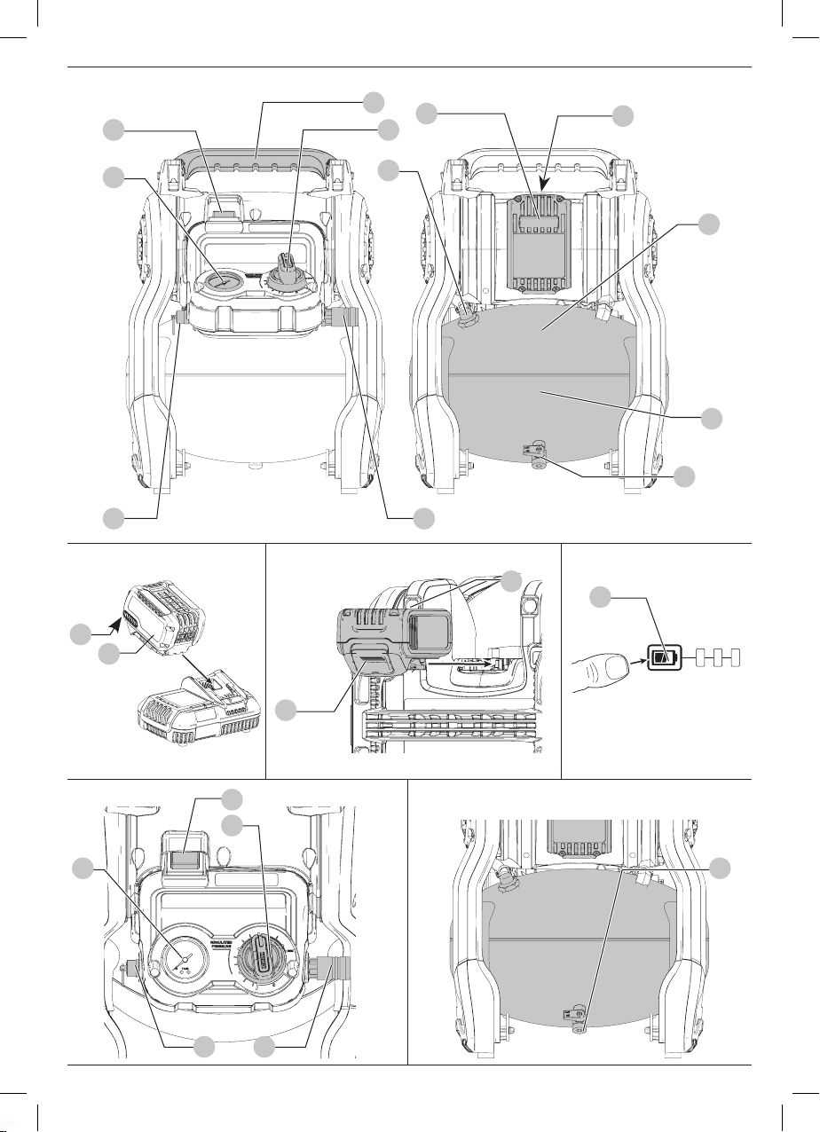
Fig. A
10
1
2
6
3
5
8
4 9
Fig. B Fig. C Fig. D
2
3
2
13
11
7
12
Fig. E
5
1
6
4 9
3
Fig. F
7
1
Page 4
ENGLISH
DeWALT
DeWALT
DeWALT
DeWALT
DeWALT
DeWALT
54V 10L CORDLESS AIRCOMPRESSOR
DCC1054
Congratulations!
You have chosen a
product development and innovation make
most reliable partners for professional power toolusers.
Technical Data
Voltage V
Type 1
Battery type Li‑Ion
Air tank capacity Liters 10
Approx. cut‑in pressure BAR 7.2
Approx. cut‑out pressure BAR 9.3
Air displacement l/min 48
Air delivery at 7 BAR l/min 31
Fuse type Time delay
Regulated pressure rating (approximate) BAR 0–9.3
Motor revolutions per minute 3400
Quick connect type Universal EU 1/4"
Pump type Oil‑less
Weight (without battery pack) kg 11.0
Noise valuesaccording to EN1012‑1
LPA (emission sound pressure level) dB(A) 79
LWA (sound power level) dB(A) 92
K (uncertainty for the given sound level) dB(A) 3
The vibration emission level given in this information sheet has
been measured in accordance with a standardised test given in
EN1012‑1 and may be used to compare one tool with another. It
may be used for a preliminary assessment ofexposure.
EC‑Declaration of Conformity
Machinery Directive
54V 10L Cordless Air Compressor
DCC1054
declares that these products described under
Technical Data are in compliance with:
2006/42/EC, EN1012‑1:2010, EN 60204‑1:2006/A1:2009.
2000/14/EC, Compressors , P<15kW,
Annex VII, Deutsche Prüf‑ und Zertifizierungsstelle für Land‑
und Forsttechnik, Spremberger Straße 1, 64823 Groß‑Umstadt,
Notified Body ID No.:0363.
tool. Years of experience, thorough
DC
one of the
DCC1054
54
quick coupling
Level of sound power according to 2000/14/EC
(Article 12, Annex III, No. 9:)
LWA (measured sound power level) dB 91
LWA (guaranteed sound power level) dB 92
These products also comply with Directive 2014/30/EU,
2014/29/EU, and 2011/65/EU. For more information, please
contact
themanual.
The undersigned is responsible for compilation of the technical
file and makes this declaration on behalf of
Markus Rompel
Director Engineering
D‑65510, Idstein, Germany
20.11.2017
at the following address or refer to the back of
, Richard‑Klinger‑Straße 11,
WARNING: To reduce the risk of injury, read the
instructionmanual.
.
Definitions: Safety Guidelines
The definitions below describe the level of severity for each
signal word. Please read the manual and pay attention to
thesesymbols.
DANGER: Indicates an imminently hazardous
situation which, if not avoided, will result in death or
seriousinjury.
WARNING: Indicates a potentially hazardous situation
which, if not avoided, could result in death or
seriousinjury.
CAUTION: Indicates a potentially hazardous situation
which, if not avoided, may result in minor or
moderateinjury.
NOTICE: Indicates a practice not related to
personal injury which, if not avoided, may result in
propertydamage.
Denotes risk of electricshock.
Denotes risk offire.
SAFETY INSTRUCTIONS
Important Safety Instructions for Use of the
Compressor
WARNING: DEATH OR SERIOUS BODILY INJURY
COULD RESULT FROM IMPROPER OR UNSAFE USE
OF COMPRESSOR. TO AVOID THESE RISKS, FOLLOW
THESE BASIC SAFETYINSTRUCTIONS.
2
Page 5

Weight
Batteries Chargers/Charge Times (Minutes)
Cat # V
Ah Weight (kg) DCB107 DCB113 DCB115 DCB118 DCB132 DCB119
DC
DCB546 18/54 6.0/2.0 1.05 270 140 90 60 90 X
DCB547 18/54 9.0/3.0 1.25 420 220 140 85 140 X
DCB181 18 1.5 0.35 70 35 22 22 22 45
DCB182 18 4.0 0.61 185 100 60 60 60 120
DCB183/B 18 2.0 0.40 90 50 30 30 30 60
DCB184/B 18 5.0 0.62 240 120 75 75 75 150
DCB185 18 1.3 0.35 60 30 22 22 22 X
DCB187 18 3.0 0.48 140 70 45 45 45 90
ENGLISH
READ ALL INSTRUCTIONS
1 . NEVER TOUCH MOVING PARTS. Never place your
hands, fingers or other body parts near the compressor’s
movingparts.
2 . NEVER OPERATE WITHOUT ALL GUARDS IN PLACE
Never operate this compressor without all guards or
safety features in place and in proper working order. If
maintenance or servicing requires the removal of a guard or
safety features, be sure to replace the guards or safety feature
before resuming operation of thecompressor.
3 . ALWAYS WEAR EYE PROTECTION. Always wear safety
goggles or equivalent eye protection. Compressed air
must never be aimed at anyone or any part of thebody.
4 . PROTECT YOURSELF AGAINST ELECTRIC SHOCK. Prevent
body contact with grounded surfaces such as pipes,
radiators, ranges and refrigeration enclosures. Never
operate the compressor in damp or wet locations. Never
leave the compressor exposed to adverse weatherconditions.
5 . DISCONNECT THE COMPRESSOR WHEN NOT IN USE.
Always disconnect the compressor from the power source and
remove the compressed air from the air tank before servicing,
inspecting, maintaining, cleaning, replacing or checking
anyparts.
6 . AVOID UNINTENTIONAL STARTING. Do not transport
the compressor over long distances, in a vehicle or in
potentially dangerous situations, for example, on a
ladder or scaffold while it is connected to its power
source or when the air tank is filled with compressed air.
Be sure the auto ON/ OFF switch is in the OFF position before
connecting the compressor to its powersource.
7 . STORE COMPRESSOR PROPERLY. When not in use, the
compressor should be stored in dry place. Keep out of
reach of children. Lock‑out the storagearea.
8 . KEEP WORK AREA CLEAN Cluttered areas invite injuries.
Clear all work areas of unnecessary tools, debris, furnitureetc.
9 . KEEP CHILDREN AWAY. Do not let visitors contact
compressor extension cord. All visitors should be kept safely
away from workarea.
10 . DRESS PROPERLY. Do not wear loose clothing or
jewellery. They can be caught in moving parts. Wear
protective hair covering to contain longhair.
11 . STAY ALERT. Watch what you are doing. Use common
sense. Do not operate compressor when you are tired.
Compressor should never be used by you if you are under
the influence of alcohol, drugs or medication that makes
youdrowsy.
12 . CHECK FOR DAMAGED PARTS AND AIR LEAKS. Before
further use of the compressor, carefully check the guard
and other parts for damage to make sure that it will
operate properly and perform its intended function.
Check for alignment of moving parts, binding of moving
parts, breakage of parts, mounting, air leak, and any
other conditions that may affect its operation. A guard
or other part that is damaged should be properly
repaired or replaced by an authorized service centre
unless otherwise indicated elsewhere in this Instruction
Manual. Have defective pressure switches replaced
by authorized service centre. Do not use compressor
if switch does not turn it on and off. Never attempt
to repair a leaking or damaged air tank. Replace tank
immediately at an authorized servicecentre.
13 . NEVER USE COMPRESSOR FOR APPLICATIONS OTHER
THAN THOSE SPECIFIED. Never use compressor for
applications other than those specified in the Instruction
Manual. Never use compressed air for breathing or
respiration. Never stand on thecompressor.
14 . HANDLE COMPRESSOR CORRECTLY. Operate the
compressor according to the instructions provided
herein. Never allow the compressor to be operated by
children, individuals unfamiliar with its operation or
unauthorisedpersonnel.
15 . KEEP ALL SCREWS, BOLTS AND COVERS TIGHTLY
IN PLACE. Keep all screws, bolts, and plates tightly
mounted. Check their conditionsperiodically.
16 . KEEP MOTOR AIR VENT CLEAN The motor air vent must
be kept clean so that air can freely flow at all times.
Check for dust build‑upfrequently.
17 . OPERATE COMPRESSOR AT THE RATED VOLTAGE.
Operate the compressor at voltages specified on their
nameplates. If using the compressor at a higher voltage
than the rated voltage, it will result in abnormally fast motor
revolution and may damage the unit and burn out themotor.
18 . NEVER USE A COMPRESSOR WHICH IS DEFECTIVE OR
OPERATING ABNORMALLY. If the compressor appears to
3
Page 6

ENGLISH
DeWALT
DeWALT
DeWALT
be operating unusually, making strange noises, or otherwise
appears defective, stop using it immediately and arrange for
repairs by an authorized servicecentre.
19 . DO NOT WIPE PLASTIC PARTS WITH SOLVENT. Solvents
such as gasoline, thinner, benzine, carbon tetrachloride,
and alcohol may damage and crack plastic parts. Do not
wipe them with such solvents. Wipe plastic parts with a soft
cloth lightly dampened with soapy water and drythoroughly.
20 . USE ONLY GENUINE REPLACEMENT PARTS. Replacement
parts not original may void your warranty and can lead
to malfunction and resulting injuries. Genuine parts are
available from yourdealer.
21 . DO NOT MODIFY THE COMPRESSOR. Do not modify
the compressor. Always contact the authorized service
centre any repairs. Unauthorised modification may
not only impair the compressor performance but may
also result in accident or injury to repair personnel who
do not have the required knowledge and technical
expertise to perform the repair operations correctly.
Unauthorised modifications may increase the risk of injury to
the user or the risk of propertydamage.
22 . TURN OFF THE SWITCH WHEN THE COMPRESSOR IS NOT
USED. When the compressor is not used, turn the switch OFF,
disconnect it from the power source and open the drain cock
to discharge the compressed air from the airtank.
23 . NEVER TOUCH HOT SURFACE. To reduce the risk of burns,
do not touch tubes, heads, cylinder andmotors.
24 . DO NOT DIRECT AIR STREAM AT BODY. Risk of injury, do
not direct air stream at persons oranimals.
25 . DRAIN TANK DAILY OR AFTER EACH USE. Open the
drain valve and tilt compressor to completely empty
accumulated water. Failure to properly drain tank may
result in excessive corrosion, which may cause sudden air tank
rupture orexplosion.
26 . DO NOT STOP COMPRESSOR BY PULLING OUT THE
BATTERY. Use the auto ON/ OFFswitch.
27 . USE ONLY RECOMMENDED AIR HANDLING PARTS
ACCEPTABLE FOR PRESSURE NOT LESS THAN 9.3 BAR
Risk of bursting. Use only recommended air handling parts
acceptable for pressures not less than 9.3bar.
28 . WEAR PROPER HEARING AND HEAD PROTECTION.
Suitable protective clothing must be worn when
operating the compressor and connected tool or
accessory. Consult the tool/ accessory manual and adhere to
any safetyrequirements.
29 . MAKE ALLOWANCE FOR ENVIRONMENTAL CONDITIONS.
Never leave the compressor in the rain. Never use the
compressor in damp or wet conditions. Provide good
lighting. Never use the compressor near combustible liquids
orgases.
30 . DO NOT OPERATE IN EXPLOSIVE ATMOSPHERES, SUCH
AS IN THE PRESENCE OF FLAMMABLE LIQUIDS, GASES OR
DUST. Compressors can create sparks which may ignite the
dust orfumes.
31 . CHECK THE PRESSURE VESSEL FOR SIGNS OF RUST AND
DAMAGE EACH TIME BEFORE USING. Do not use the
compressor with a damaged or rusty pressurevessel.
Residual Risks
In spite of the application of the relevant safety regulations
and the implementation of safety devices, certain residual risks
cannot be avoided. These are:
• Impairment ofhearing.
• Risk of personal injury due to flyingparticles.
• Risk of burns due to accessories becoming hot
duringoperation.
• Risk of personal injury due to prolongeduse.
• Risk of personal injury if the adjusted pressure is higher than
maximum pressure of thetool.
Electrical Safety
The electric motor has been designed for one voltage only.
Always check that the battery pack voltage corresponds to the
voltage on the rating plate. Also make sure that the voltage of
your charger corresponds to that of yourmains.
Your
accordance with EN60335; therefore no earth wire
isrequired.
If the supply cord is damaged, it must be replaced by a
specially prepared cord available through the
serviceorganisation.
charger is double insulated in
Mains Plug Replacement
(U.K. & Ireland Only)
If a new mains plug needs to be fitted:
• Safely dispose of the oldplug.
• Connect the brown lead to the live terminal in theplug.
• Connect the blue lead to the neutralterminal.
WARNING: No connection is to be made to the
earthterminal.
Follow the fitting instructions supplied with good quality plugs.
Recommended fuse: 3A.
Using an Extension Cable
An extension cord should not be used unless absolutely
necessary. Use an approved extension cable suitable for
the power input of your charger (see Technical Data). The
minimum conductor size is 1mm2; the maximum length
is30m.
When using a cable reel, always unwind the cablecompletely.
SAVE THESE INSTRUCTIONS
Chargers
chargers require no adjustment and are designed to be
as easy as possible tooperate.
4
Page 7

Important Safety Instructions for All
DeWALT
DeWALT
Battery Chargers
SAVE THESE INSTRUCTIONS: This manual contains important
safety and operating instructions for compatible battery
chargers (refer to TechnicalData).
• Before using charger, read all instructions and cautionary
markings on charger, battery pack, and product using
batterypack.
WARNING: Shock hazard. Do not allow any liquid to get
inside charger. Electric shock mayresult.
WARNING: We recommend the use of a residual current
device with a residual current rating of 30mA orless.
CAUTION: Burn hazard. To reduce the risk of injury,
charge only
batteries may burst causing personal injury anddamage.
CAUTION: Children should be supervised to ensure that
they do not play with theappliance.
NOTICE: Under certain conditions, with the charger
plugged into the power supply, the exposed charging
contacts inside the charger can be shorted by foreign
material. Foreign materials of a conductive nature such
as, but not limited to, steel wool, aluminum foil or any
buildup of metallic particles should be kept away from
charger cavities. Always unplug the charger from the
power supply when there is no battery pack in the cavity.
Unplug charger before attempting to clean
• DO NOT attempt to charge the battery pack with any
chargers other than the ones in this manual. The charger
and battery pack are specifically designed to worktogether.
• These chargers are not intended for any uses other than
charging
may result in risk of fire, electric shock orelectrocution.
• Do not expose charger to rain orsnow.
• Pull by plug rather than cord when disconnecting
charger. This will reduce risk ofdamage to electric plug
andcord.
• Make sure that cord is located so that it will not be
stepped on, tripped over, or otherwise subjected to
damage orstress.
• Do not use an extension cord unless it is absolutely
necessary. Use of improper extension cord could result in risk
of fire,electric shock, orelectrocution.
• Do not place any object on top of charger or place
the charger on a soft surface that might block the
ventilation slots and result in excessive internal heat.
Place the charger in a position away from any heat source. The
charger is ventilated through slots in the top and the bottom
of thehousing.
• Do not operate charger with damaged cord or plug—
have them replacedimmediately.
• Do not operate charger if it has received a sharp blow,
been dropped, or otherwise damaged in any way. Take it
to an authorised servicecentre.
• Do not disassemble charger; take it to an authorised
service centre when service or repair is required. Incorrect
rechargeable batteries. Other types of
rechargeable batteries. Any other uses
ENGLISH
reassembly may result in a risk of electric shock, electrocution
orfire.
• In case of damaged power supply cord the supply cord must
be replaced immediately by the manufacturer, its service agent
or similar qualified person to prevent anyhazard.
• Disconnect the charger from the outlet before
attempting any cleaning. This will reduce the risk of
electric shock. Removing the battery pack will not reduce
thisrisk.
• NEVER attempt to connect two chargerstogether.
• The charger is designed to operate on standard
230V household electrical power. Do not attempt to
use it on any other voltage. This does not apply to the
vehicularcharger.
Charging a Battery (Fig. B)
1. Plug the charger into an appropriate outlet before inserting
batterypack.
2. Insert the battery pack
battery pack is fully seated in the charger. The red (charging)
light will blink repeatedly indicating that the charging
process hasstarted.
3. The completion of charge will be indicated by the red
light remaining ON continuously. The battery pack is fully
charged and may be used at this time or left in the charger.
To remove the battery pack from the charger, push the
battery release button
NOTE: To ensure maximum performance and life of lithium‑ion
battery packs, charge the battery pack fully before firstuse.
2
into the charger, making sure the
3
on the batterypack.
Charger Operation
Refer to the indicators below for the charge status of the
batterypack.
Charge Indicators
Charging
Fully Charged
Hot/Cold Pack Delay*
* The red light will continue to blink, but a yellow indicator light
will be illuminated during this operation. Once the battery pack
has reached an appropriate temperature, the yellow light will
turn off and the charger will resume the chargingprocedure.
The compatible charger(s) will not charge a faulty battery pack.
The charger will indicate faulty battery by refusing to light or by
displaying problem pack or charger blinkpattern.
NOTE: This could also mean a problem with acharger.
If the charger indicates a problem, take the charger and battery
pack to be tested at an authorised servicecentre.
Hot/Cold Pack Delay
When the charger detects a battery pack that is too hot or too
cold, it automatically starts a Hot/Cold Pack Delay, suspending
charging until the battery pack has reached an appropriate
temperature. The charger then automatically switches to the
5
Page 8

ENGLISH
DeWALT
DeWALT
pack charging mode. This feature ensures maximum battery
packlife.
A cold battery pack will charge at a slower rate than a warm
battery pack. The battery pack will charge at that slower rate
throughout the entire charging cycle and will not return to
maximum charge rate even if the battery packwarms.
The DCB118 charger is equipped with an internal fan designed
to cool the battery pack. The fan will turn on automatically
when the battery pack needs to be cooled. Never operate the
charger if the fan does not operate properly or if ventilation slots
are blocked. Do not permit foreign objects to enter the interior
of thecharger.
Electronic Protection System
XR Li‑Ion tools are designed with an Electronic Protection
System that will protect the battery pack against overloading,
overheating or deepdischarge.
The tool will automatically turn off if the Electronic Protection
System engages. If this occurs, place the lithium‑ion battery
pack on the charger until it is fullycharged.
Wall Mounting
These chargers are designed to be wall mountable or to sit
upright on a table or work surface. If wall mounting, locate the
charger within reach of an electrical outlet, and away from a
corner or other obstructions which may impede air flow. Use
the back of the charger as a template for the location of the
mounting screws on the wall. Mount the charger securely using
drywall screws (purchased separately) at least 25.4mm long
with a screw head diameter of 7–9mm, screwed into wood to
an optimal depth leaving approximately 5.5mm of the screw
exposed. Align the slots on the back of the charger with the
exposed screws and fully engage them in theslots.
Charger Cleaning Instructions
WARNING: Shock hazard. Disconnect the charger
from the AC outlet before cleaning. Dirt and grease
may be removed from the exterior of the charger using a
cloth or soft non‑metallic brush. Do not use water or any
cleaning solutions. Never let any liquid get inside the tool;
never immerse any part of the tool into aliquid.
Battery Packs
Important Safety Instructions for All
Battery Packs
When ordering replacement battery packs, be sure to include
catalogue number andvoltage.
The battery pack is not fully charged out of the carton. Before
using the battery pack and charger, read the safety instructions
below. Then follow charging proceduresoutlined.
READ ALL INSTRUCTIONS
• Do not charge or use battery in explosive atmospheres,
such as in the presence of flammable liquids, gases or
dust. Inserting or removing the battery from the charger may
ignite the dust orfumes.
• Never force battery pack into charger. Do not modify
battery pack in any way to fit into a non‑compatible
charger as battery pack may rupture causing serious
personalinjury.
• Charge the battery packs only in
• DO NOT splash or immerse in water or otherliquids.
• Do not store or use the tool and battery pack in
locations where the temperature may reach or exceed
40 ˚C (104 ˚F) (such as outside sheds or metal buildings
insummer).
• Do not incinerate the battery pack even if it is severely
damaged or is completely worn out. The battery pack can
explode in a fire. Toxic fumes and materials are created when
lithium‑ion battery packs areburned.
• If battery contents come into contact with the skin,
immediately wash area with mild soap and water. If
battery liquid gets into the eye, rinse water over the open eye
for 15 minutes or until irritation ceases. If medical attention
is needed, the battery electrolyte is composed of a mixture of
liquid organic carbonates and lithiumsalts.
• Contents of opened battery cells may cause respiratory
irritation. Provide fresh air. If symptoms persists, seek
medicalattention.
WARNING: Burn hazard. Battery liquid may be flammable
if exposed to spark orflame.
WARNING: Never attempt to open the battery pack for
any reason. If battery pack case is cracked or damaged,
do not insert into charger. Do not crush, drop or damage
battery pack. Do not use a battery pack or charger that
has received a sharp blow, been dropped, run over or
damaged in any way (i.e., pierced with a nail, hit with
a hammer, stepped on). Electric shock or electrocution
may result. Damaged battery packs should be returned to
service centre forrecycling.
WARNING: Fire hazard. Do not store or carry the
battery pack so that metal objects can contact
exposed battery terminals. For example, do not place
the battery pack in aprons, pockets, tool boxes, product kit
boxes, drawers, etc., with loose nails, screws, keys,etc.
CAUTION: When not in use, place tool on its side on
a stable surface where it will not cause a tripping
or falling hazard. Some tools with large battery packs
will stand upright on the battery pack but may be easily
knockedover.
Transportation
WARNING: Fire hazard. Transporting batteries can
possibly cause fire if the battery terminals inadvertently
come in contact with conductive materials. When
transporting batteries, make sure that the battery
terminals are protected and well insulated from materials
that could contact them and cause a shortcircuit.
batteries comply with all applicable shipping
regulations as prescribed by industry and legal standards which
include UN Recommendations on the Transport of Dangerous
Goods; International Air Transport Association (IATA) Dangerous
Goods Regulations, International Maritime Dangerous Goods
(IMDG) Regulations, and the European Agreement Concerning
chargers.
6
Page 9

The International Carriage of Dangerous Goods by Road (ADR).
DeWALT
DeWALT
DeWALT
DeWALT
DeWALT
DeWALT
DeWALT
DeWALT
Lithium‑ion cells and batteries have been tested to section 38.3
of the UN Recommendations on the Transport of Dangerous
Goods Manual of Tests andCriteria.
In most instances, shipping a
excepted from being classified as a fully regulated Class 9
Hazardous Material. In general, only shipments containing a
lithium‑ion battery with an energy rating greater than 100 Watt
Hours (Wh) will require being shipped as fully regulated Class 9.
All lithium‑ion batteries have the Watt Hour rating marked on
the pack. Furthermore, due to regulation complexities,
does not recommend air shipping lithium‑ion battery packs
alone regardless of Watt Hour rating. Shipments of tools with
batteries (combo kits) can be air shipped as excepted if the Watt
Hour rating of the battery pack is no greater than 100Whr.
Regardless of whether a shipment is considered excepted
or fully regulated, it is the shipper's responsibility to consult
the latest regulations for packaging, labeling/marking and
documentationrequirements.
The information provided in this section of the manual is
provided in good faith and believed to be accurate at the time
the document was created. However, no warranty, expressed or
implied, is given. It is the buyer’s responsibility to ensure that its
activities comply with the applicableregulations.
Transporting the FLEXVOLTTM Battery
The
andTransport.
Use Mode: When the FLEXVOLTTM battery stands alone or is in
a
18V product, it will operate as an 18V battery. When
the FLEXVOLTTM battery is in a 54V or a 108V (two 54V batteries)
product, it will operate as a 54Vbattery.
Transport Mode: When the cap is attached to the FLEXVOLTTM
battery, the battery is in Transport mode. Keep the cap for
shipping.
When in Transport mode, strings
of cells are electrically
disconnected within the pack
resulting in 3 batteries with a
lower Watt hour (Wh) rating as compared to 1 battery with a
higher Watt hour rating. This increased quantity of 3 batteries
with the lower Watt hour rating can exempt the pack from
certain shipping regulations that are imposed upon the higher
Watt hour batteries.
For example, the Transport
Wh rating might indicate
3x36 Wh, meaning 3
batteries of 36 Wh each.
The Use Wh rating might
indicate 108Wh (1batteryimplied).
FLEXVOLTTM battery has two modes: Use
battery pack will be
Example of Use and Transport Label Marking
Storage Recommendations
1. The best storage place is one that is cool and dry away
from direct sunlight and excess heat or cold. For optimum
battery performance and life, store battery packs at room
temperature when not inuse.
2. For long storage, it is recommended to store a fully charged
battery pack in a cool, dry place out of the charger for
optimalresults.
NOTE: Battery packs should not be stored completely
depleted of charge. The battery pack will need to be recharged
beforeuse.
Labels on Charger and Battery Pack
In addition to the pictographs used in this manual, the
labels on the charger and the battery pack may show the
followingpictographs:
Read instruction manual beforeuse.
See Technical Data for chargingtime.
Do not probe with conductiveobjects.
Do not charge damaged batterypacks.
Do not expose to water.
Have defective cords replacedimmediately.
Charge only between 4 ˚C and 40 ˚C.
Only for indooruse.
Discard the battery pack with due care for
theenvironment.
Charge
than the designated
other dangeroussituations.
Do not incinerate the batterypack.
USE (without transport cap). Example: Wh rating
indicates 108 Wh (1 battery with 108 Wh).
TRANSPORT (with built‑in transport cap). Example:
Wh rating indicates 3 x 36 Wh (3batteries of 36Wh).
battery packs only with designated
chargers. Charging battery packs other
charger may make them burst or lead to
batteries with a
Battery Type
The DCC1054 operates on a 54 volt battery pack.
These battery packs may be used: DCB546, DCB547. Refer to
Technical Data for moreinformation.
ENGLISH
7
Page 10

ENGLISH
DeWALT
Package Contents
The package contains:
1 Air compressor
2 Li‑Ion battery packs (T2 models only)
1 Charger (T2 models only)
1 Instruction manual
NOTE: Battery packs, chargers and kitboxes are not included
with N‑models.
• Check for damage to the tool, parts or accessories which may
have occurred duringtransport.
• Take the time to thoroughly read and understand this manual
prior tooperation.
Markings on Tool
The following pictograms are shown on the tool:
Read instruction manual beforeuse.
Wear earand eyeprotection.
Air tankcapacity.
Approx. cut‑outpressure.
Airdisplacement.
Oil‑lesspump.
Set outlet pressure to zero before the air hose is
attached orremoved.
Risk of hightemperatures.
CAUTION: the compressor contains some parts
which might reach hightemperatures.
Risk of accidental start‑up.
NOTICE: The compressor could start
automatically in case of a black‑out and
subsequentreset.
WARNING: Compressor unit may start
withoutwarning.
Outdoor noise level
Important Information
Read and understand all of the operating instructions, safety
precautions and warnings in the Instruction Manual before
operating or maintaining this compressor. Most accidents that
result from compressor operation and maintenance are caused by
the failure to observe basic safety rules or precautions. An accident
can often be avoided by recognizing a potentially hazardous
situation before it occurs, and by observing appropriate safety
8
procedures. Basic safety precautions are outlined in the “SAFETY”
section of this Instruction Manual and in the sections which
contain the operation and maintenance instructions. Hazards
that must be avoided to prevent bodily injury or machine damage
are identified by WARNINGS on the compressor and in this
InstructionManual.
Date Code Position (Fig. A)
The date code
is printed on a label on the rear of thetank.
Example:
13
, which also includes the year of manufacture,
2017 XX XX
Year of Manufacture
Description (Fig. A)
WARNING: Never modify the power tool or any part of it.
Damage or personal injury couldresult.
1
Auto On/Off switch
2
Battery
3
Battery release button
4
Safety valve
5
Tank pressure gauge
6
One‑Turn regulator
7
Drain valve
8
Check valve
9
Quick‑connect coupler
10
Carry handle
11
Tank
Intended Use
Your compressor is designed for professional finish nailing and
staplingapplications.
DO NOT use under wet conditions or in the presence
of flammable liquids orgases. DO NOT use or store the
compressor at temperatures below 0°C.
Your compressor is a professional power tool.
DO NOT let children come into contact with the tool.
Supervision is required when inexperienced operators use
thistool.
• Young children and the infirm. This appliance is not
intended for use by young children or infirm persons
without supervision.
• This product is not intended for use by persons (including
children) suffering from diminished physical, sensory or
mental abilities; lack of experience, knowledge or skills
unless they are supervised by a person responsible for their
safety. Children should never be left alone with thisproduct.
ASSEMBLY AND ADJUSTMENTS
WARNING: To reduce the risk of serious personal
injury, turn tool off and disconnect battery pack
before making any adjustments or removing/
installing attachments or accessories. An accidental
start‑up can causeinjury.
WARNING: Use only
battery packs andchargers.
Page 11

Inserting and Removing the Battery Pack
DeWALT
from the Tool (Fig. C, D)
NOTE: Make sure your battery pack
To Install the Battery Pack into the Tool
Handle
1. Align the battery pack
handle (Fig.C).
2. Slide it into the handle until the battery pack is firmly seated
in the tool and ensure that you hear the lock snap intoplace.
To Remove the Battery Pack from the Tool
1. Press the release button
out of the toolhandle.
2. Insert battery pack into the charger as described in the
charger section of thismanual.
Fuel Gauge Battery Packs (Fig. D)
Some
consists of three green LED lights that indicate the level of
charge remaining in the batterypack.
To actuate the fuel gauge, press and hold the fuel gauge
button
illuminate designating the level of charge left. When the level
of charge in the battery is below the usable limit, the fuel gauge
will not illuminate and the battery will need to berecharged.
NOTE: The fuel gauge is only an indication of the charge left on
the battery pack. It does not indicate tool functionality and is
subject to variation based on product components, temperature
and end‑userapplication.
battery packs include a fuel gauge which
12
. A combination of the three green LED lights will
2
is fullycharged.
2
with the rails inside the tool’s
3
and firmly pull the battery pack
OPERATION
Instructions for Use
WARNING: Always observe the safety instructions and
applicableregulations.
WARNING: To reduce the risk of serious personal
injury, turn tool off and disconnect battery pack
before making any adjustments or removing/
installing attachments or accessories. An accidental
start‑up can causeinjury.
WARNING: Ensure the compressor is placed firmly
to a stable flat surface. Failure to do so could cause
the compressor to be unstable and fall causing
personalinjury.
Know Your Air Compressor
READ THIS OWNER’S MANUAL AND SAFETY RULES BEFORE
OPERATING YOUR UNIT. Compare the illustrations with your unit
to familiarise yourself with the location of various controls and
adjustments. Save this manual for futurereference.
Description of Operation (Fig. A)
Become familiar with these controls before operating theunit.
Auto On(I)/Off(O) Switch
position to provide automatic power to the pressure switch and
"Off" to remove power at the end of eachuse.
1
: Place this switch in the "AutoOn"
ENGLISH
Pressure Switch (not shown): The pressure switch
automatically starts the motor when the air tank pressure drops
below the factory set "cut‑in" pressure. It stops the motor when
the air tank pressure reaches the factory set "cut‑out"pressure.
Safety Valve
air compressor at its "cut‑out" pressure setting, the safety
valve will protect against high pressure by "popping out" at its
factory set pressure (slightly higher than the pressure switch
"cut‑out"setting).
Tank Pressure Gauge
the reserve air pressure in thetank.
One-Turn Regulator
the quick‑connect outlet. Turn the One‑Turn regulator clockwise
to increase pressure or anti‑clockwise to decrease pressure. Stop
when indicator matches with desired outlet pressure.
Cooling System (not shown): This compressor contains an
advanced design cooling system. At the heart of this cooling
system is an engineered fan. It is perfectly normal for this fan
to blow air through the vent holes in large amounts. You know
that the cooling system is working when air is beingexpelled.
Air Compressor Pump (not shown): Compresses air into the
air tank. Working air is not available until the compressor has
raised the air tank pressure above that required at the airoutlet.
Drain Valve
tank and is used to drain condensation at the end of eachuse.
Check Valve
check valve is "open", allowing compressed air to enter the air
tank. When the air compressor reaches "cut‑out" pressure, the
check valve "closes", allowing air pressure to remain inside the
airtank.
Motor Overload Protector (not shown): The motor has
a thermal overload protector. If the motor overheats for
any reason, the overload protector will shut off the motor.
The motor must be allowed to cool down before restarting.
Torestart:
1. Set the Auto On/Off switch to "Off".
2. Remove thebattery.
3. Allow the motor tocool.
4. Replace thebattery.
5. Set the Auto On/Off switch to "Auto On"position.
Quick-Connect Coupler
coupling body accepts industrial Push‑to‑Connectplugs.
4
: If the pressure switch does not shut off the
5
: The tank pressure gauge indicates
6
: Controls the air pressure available at
7
: The drain valve is located at the base of the air
8
: When the air compressor is operating, the
9
: The Universal EU 1/4" quick
How to Use Your Unit (Fig. E)
How to Stop
WARNING: When loosening the hose coupling from the
quick‑connect coupler
must be held by hand in order to avoid injuries caused by
the recoilinghose.
1. Set the Auto On/Off switch
2. Turn the One‑Turn regulator
outlet pressure tozero.
3. Remove hose andtool/accessories.
4. Remove battery when not in use.
9
, the coupling piece of the hose
1
to "Off".
6
anti‑clockwise to set the
9
Page 12

ENGLISH
DeWALT
DeWALT
Before Starting
WARNING: Do not operate this unit until you read
this instruction manual for safety, operation and
maintenanceinstructions.
Before Each Start‑Up
1. Set the Auto On/Off switch
2. Remove battery. (Refer to Installing and Removing the
Battery Pack from the Tool)
3. Turn the One‑Turn regulator
outlet pressure to zero.
4. Attach hose andtool/accessories.
WARNING: Risk of unsafe operation. Firmly grasp
air hose in hand when installing or disconnecting to
prevent hosewhip.
WARNING: Risk of unsafe operation. Do not use
damaged or wornaccessories.
NOTE: The hose or accessory will require a quick connect plug if
the air outlet is equipped with a quick connect body
WARNING: Risk of Bursting. Too much air pressure
causes a hazardous risk of bursting. Check the
manufacturer’s maximum pressure rating for air tools
and accessories. The regulator outlet pressure must never
exceed the maximum pressurerating.
NOTICE: Risk of property damage. Compressed air
from the unit may contain wa ter condensation and oil
mist. Do not spray un fil tered air at an item that could be
damaged by moisture. Some air tools and accessories may
require filtered air. Read the in struc tions for the air tools
andaccessories.
How to Start
1. Install the battery into thecompressor.
2. Attach hose andtool/accessories.
3. Set the Auto On/Off switch
tank pressure to build. Motor will stop when tank pressure
reaches "cut‑out"pressure.
4. Turn One‑Turn regulator
and stop when desired pressure isreached.
NOTE: Make sure that the desired pressure is not more
than the maximum pressure of the connected hose or the
connectedtool.
WARNING: Risk of unsafe operation. If any unusual
noise or vibration is noticed, stop the compressor
immediately and have it checked by a trained
servicetechnician.
WARNING: Ensure the regulator is set to a pressure lower
than the maximum operating pressure of thetool.
The compressor is ready foruse.
1
to "Off".
6
counterclockwise to set the
9
1
to "Auto On" and allow
6
clockwise to increase pressure
.
MAINTENANCE
Your
over a long period of time with a minimum of maintenance.
Continuous satisfactory operation depends upon proper tool
care and regularcleaning.
power tool has been designed to operate
WARNING: To reduce the risk of serious personal
injury, turn tool off and disconnect battery pack
before making any adjustments or removing/
installing attachments or accessories. An accidental
start‑up can causeinjury.
The charger and battery pack are notserviceable.
Customer Responsibilities
Before each use Daily or after each use
Check Safety Valve X
Drain Tank X
Check for air leaks X
Check for unusual noise/vibration X
Check hose and tool connection X
Adjustment of pressure control X
WARNING: Risk of unsafe operation. Unit cycles
automatically when power is on. When performing
maintenance, you may be exposed to voltage sources,
compressed air, or moving parts. Personal injuries can
occur. Before performing any maintenance or repair,
disconnect power source from the compressor and bleed
off all airpressure.
NOTE: Refer to the Operation section for the location
ofcontrols.
To Check Safety Valve (Fig. E)
WARNING: Risk of Bursting. If the
safety valve does not work properly,
over‑pressurization may occur, causing air
tank rupture or anexplosion.
WARNING: Risk from Flying Objects. Always wear
certified eye protection with sideshields.
Before starting compressor, pull the ring on the safety valve
to make sure that the safety valve operates freely. If the valve
is stuck or does not operate smoothly. Contact the
servicecentre.
WARNING: Do not pull the ring of the safety valve if the
tank is under pressure!
To Drain Tank (Fig. E, F)
WARNING: Risk of Unsafe Operation. Air
tanks contain high pressure air. Keep face
and other body parts away from outlet of
drain. Use eye protection when draining as
debris can be kicked up intoface.
WARNING: Risk from noise. Always wear
proper hearing protection during use. Under
some conditions and duration of use, noise from this
product may contribute to hearingloss.
NOTE: All compressed air systems generate condensate that
accumulates in any drain point (e.g., tanks, filter, aftercoolers,
dryers). This condensate contains lubricating oil and/or
substances which may be regulated and must be disposed of in
accordance with currentregulations.
4
10
Page 13

WARNING: Risk of Bursting. Water will condense in the
DeWALT
DeWALT
DeWALT
air tank. If not drained, water will corrode and weaken the
air tank causing a risk of air tankrupture.
NOTICE: Risk of Property Damage. Drain water from
air tank may contain oil and rust which can causestains.
1. Set the Auto On/Off switch
2. Remove thebattery.
3. Turn the One‑Turn regulator
outlet pressure tozero.
4. Remove the air tool oraccessory.
WARNING: When loosening the hose coupling from the
quick‑connect coupler
must be held by hand in order to avoid injuries caused by
the recoilinghose.
5. Place a suitable container under the drain valve to
catchdischarge.
6. Pull ring on safety valve
tank until tank pressure is approximately 1.4 BAR. Release
safety valvering.
7. Drain water from air tank by opening drain valve
bottom oftank.
8. After the water has been drained, close the drain valve. The
air compressor can now bestored.
NOTE: If drain valve is blocked, release all air pressure by
connecting a tool to the airline and operating it until tank
pressure is zero BAR and contact the
1
to "Off".
6
counterclockwise to set the
9
, the coupling piece of the hose
4
allowing air to bleed from the
7
servicecentre.
on
Storage
Before you store the air compressor, make sure you do
thefollowing:
1. Review the Maintenance section and perform scheduled
maintenance asnecessary.
2. Always toggle Auto On/Off Switch to "Off" and remove
battery. Drain water from air tank. Refer to To Drain Tank
underMaintenance.
WARNING: Water will condense in the air tank. If not
drained, water will corrode and weaken the air tank
causing a risk of air tankrupture.
3. Store the air compressor in a clean and drylocation.
4. Make sure the air compressor is secured in such a way that it
cannot be started up again by any unauthorizedperson.
5. Frost destroys the pump and accessories as both always
contain water. If there is a risk of danger of frost, store in
frost‑freeconditions.
Cleaning
WARNING: Blow dirt and dust out of the main housing
with dry air as often as dirt is seen collecting in and around
the air vents. Wear approved eye protection and approved
dust mask when performing thisprocedure.
WARNING: Never use solvents or other harsh chemicals
for cleaning the non‑metallic parts of the tool. These
chemicals may weaken the materials used in these parts.
ENGLISH
Use a cloth dampened only with water and mild soap.
Never let any liquid get inside the tool; never immerse any
part of the tool into aliquid.
Optional Accessories
WARNING: Since accessories, other than those offered
by
of such accessories with this tool could be hazardous.
To reduce the risk of injury, only
accessories should be used with thisproduct.
Consult your dealer for further information on the
appropriateaccessories.
, have not been tested with this product, use
recommended
Protecting the Environment
Separate collection. Products and batteries marked
with this symbol must not be disposed of with normal
householdwaste.
Products and batteries contain materials that can
be recovered or recycled reducing the demand for raw
materials. Please recycle electrical products and batteries
according to local provisions. Further information is available at
www.2helpU.com.
Rechargeable Battery Pack
This long life battery pack must be recharged when it fails
to produce sufficient power on jobs which were easily done
before. At the end of its technical life, discard it with due care for
our environment:
• Run the battery pack down completely, then remove it from
thetool.
• Li‑Ion cells are recyclable. Take them to your dealer or a
local recycling station. The collected battery packs will be
recycled or disposed ofproperly.
GLOSSARY
Cut-In Pressure: While the motor is off, air tank pressure drops
when accessory is used. When the tank pressure drops to a
certain low level the motor will restart automatically. The low
pressure at which the motor automatically restarts is called
cut-inpressure.
Cut-Out Pressure: When an air compressor is turned on and
begins to run, air pressure in the air tank begins to build. It
builds to a certain high pressure before the motor automatically
shuts off, protecting your air tank from pressure higher than
its capacity. The high pressure at which the motor shuts off is
called cut-outpressure.
Duty Cycle: This air compressor pump is capable of running
continuously. However, to prolong the life of your air
compressor, it is recommended that a 50%–75% average duty
cycle be maintained; that is, the air compressor pump should
not run more than 30–45 minutes in any givenhour.
11
Page 14

ENGLISH
DeWALT
Troubleshooting Guide
This section provides a list of the more frequently encountered malfunctions, their causes and corrective actions. The operator
or maintenance personnel can perform some corrective actions, and others may require the assistance of a qualified
technician or yourdealer.
Code Possible Cause Possible Solution
Pressure switch does not shut off motor when
1
compressor reaches cut‑out pressure
2 Pressure switch cut‑out too high Contact a DeWALT service organisation.
Tube fittings are not tight enough Tighten fittings where air can be heard escaping. Check fittings with soapy water solution. Do
3
Defective air tank Air tank must be replaced. Do not repair the leak. Contact a DeWALT service organisation.
4
Leaking seals Contact a DeWALT service organisation.
5
Defective safety valve Operate safety valve manually by pulling on ring. If valve still leaks, it must be replaced. Contact a
6
Regulator is not adjusted correctly for accessory
7
being used
8 Prolonged excessive use of air Decrease amount of air usage.
Compressor doesn't provide enough air
9
for accessory
11 Check valve restricted Contact a DeWALT service organisation.
12 Air leaks Tighten fittings.
Regulator is damaged Contact a DeWALT service organisation.
13
Motor overload protection switch has tripped Refer to Motor Overload Protector under Description of Operations. If motor overload protection
14
Tank pressure exceeds pressure switch
15
cut‑in pressure
16 Loose electrical connections Contact a DeWALT service organisation.
17 Possible defective motor Contact a DeWALT service organisation.
Paint spray on internal motor parts Contact a DeWALT service organisation. Do not operate the compressor in the paint spray area. Refer to
18
Pump does not run because tank pressure is
19
above cut‑in pressure.
Pump does not run due to safety fault. Cycle Auto On/Off Switch from "Off" to "Auto On."
20
Set the Auto On/Off switch to "Off" and remove the batttery, if the unit does not shut off contact a
DeWALT service organisation.
Not Overtighten.
WARNING: Risk of bursting. Do not drill into, weld or otherwise modify air tank or it will
weaken. The air tank can rupture or explode.
DeWALT service organisation.
It is normal for some pressure drop to occur when an accessory is used, adjust the One‑Turn regulator
as instructed in One‑Turn Regulator under Description of Operations if pressure drop is excessive.
NOTE: Adjust the regulated pressure under flow conditions while accessory is being used.
Check the accessory air requirement. If it is higher than the Air Delivery (l/min) or pressure supplied by
your air compressor, a more powerful compressor is needed to operate accessory.
trips frequently, contact a DeWALT service organisation.
Motor will start automatically when tank pressure drops below cut‑in pressure of pressure switch.
flammable vapor warning.
Drain tank to below cut‑in pressure when pump turns on.
Troubleshooting Codes
Problem Code
Excessive air tank pressure‑safety valve pops off 1, 2
Air leaks 3
Air leaks in air tank or at air tank welds 4
Air leaks between head and valve plate 5
Air leaks from safety valve 6
Compressor is not supplying enough air to operate accessories 7, 8, 9, 10, 11, 12
Regulator knob has continuous air leak 13
Regulator will not shut off air outlet 13
Motor will not run 6, 14, 15, 16, 17, 18, 19, 20
12
Page 15

Page 16

Belgique et
Luxembourg België en Luxemburg
DeWALT - Belgium BVBA
Egide Walschaertsstraat 16
2800 Mechelen
Tel: NL 32 15 47 37 63
Tel: FR 32 15 47 37 64
Fax: 32 15 47 37 99
www.dewalt.be
enduser.BE@SBDinc.com
Danmark DeWALT (Stanley Black&Decker AS)
Roskildevej 22
2620 Albertslund
Tel: 70 20 15 10
Fax: 70 22 49 10
www.dewalt.dk
kundeservice.dk@sbdinc.com
Deutschland DeWALT
Richard Klinger Str. 11
65510 Idstein
Tel: 06126-21-0
Fax: 06126-21-2770
www.dewalt.de
infodwge@sbdinc.com
Ελλάς DeWALT (Ελλάς) Α.Ε.
EΔΡΑ-ΓΡΑΦΕΙΑ : Στράβωνος 7
& Λ. Βουλιαγμένης, Γλυφάδα 166 74, Αθήνα
SERVICE : Ημερος Τόπος 2 (Χάνι Αδάμ) – 193 00 Ασπρόπυργος
Τηλ: 00302108981616
Φαξ: 00302108983570
www.dewalt.gr
Greece.Service@sbdinc.com
España DeWALT Ibérica, S.C.A.
Parc de Negocios “Mas Blau”
Edificio Muntadas, c/Bergadá, 1, Of. A6
08820 El Prat de Llobregat (Barcelona)
Tel: 934 797 400
Fax: 934 797 419
www.dewalt.es
respuesta.postventa@sbdinc.com
France DeWALT
5, allée des Hêtres
BP 60105, 69579 Limonest Cedex
Tel: 04 72 20 39 20
Fax: 04 72 20 39 00
www.dewalt.fr
scufr@sbdinc.com
Schweiz
Suisse
Svizzera
DeWALT
In der Luberzen 42
8902 Urdorf
Tel: 044 - 755 60 70
Fax: 044 - 730 70 67
www.dewalt.ch
service@rofoag.ch
Ireland DeWALT
Building 4500, Kinsale Road
Cork Airport Business Park
Cork, Ireland
Tel: 00353-2781800
Fax: 01278 1811
www.dewalt.ie
Sales.ireland@sbdinc.com
Italia DeWALT
via Energypark 6
20871 Vimercate (MB), IT
Tel: 800-014353
39 039-9590200
Fax: 39 039-9590311
www.dewalt.it
Nederlands DeWALT
Netherlands BVPostbus 83,
6120 AB BORN
Tel: 31 164 283 063
Fax: 31 164 283 200
www.dewalt.nl
Norge DeWALT
Postboks 4613
0405 Oslo, Norge
Tel: 45 25 13 00
Fax: 45 25 08 00
www.dewalt.no
kundeservice.no@sbdinc.com
Österreich DeWALT
Werkzeug Vertriebsges m.b.H
Oberlaaerstrasse 248, A-1230 Wien
Tel: 01 - 66116 - 0
Fax: 01 - 66116 - 614
www.dewalt.at
service.austria@sbdinc.com
Portugal DeWALT
Ed. D Dinis, Quina da Fonte
Rua dos Malhoes 2 2A 2º Esq.
Oeiras e S. Juliao da Barra, paço de Arcos e Caxias
2770 071 Paço de Arcos
Tel: +351 214667500
Fax: +351214667580
www.dewalt.pt
resposta.posvenda@sbdinc.com
Suomi DeWALT
PL47
00521 Helsinki, Suomi
Puh: 010 400 4333
Faksi: 0800 411 340
www.dewalt.fi
asiakaspalvelu.fi@sbdinc.com
Sverige DeWALT
BOX 94
43122 Mölndal
Sverige
Tel: 031 68 61 60
Fax: 031 68 60 08
www.dewalt.se
kundservice.se@sbdinc.com
Türkiye
Sanayi ve Ticareet Bakanlığı tebliğince kullanim ömrü 7 yıldır.
Stanley Black & Decker Turkey Alet Üretim San. Tic. Ltd.Şti.
Kozyataği Mh Değirmen Sk.
Nida Kule No: 18 Kat: 6, 34742
Kadıköy, İstanbul, Türkiye
Tel: +90 216 665 2900
Faks: +90 216 665 2901
www.dewalt.com.tr
info-tr@sbdinc.com
United
Kingdom
DeWALT, 210 Bath Road;
Slough, Berks SL1 3YD
Tel: 01753-567055
Fax: 01753-572112
www.dewalt.co.uk
emeaservice@sbdinc.com
Australia DeWALT
810 Whitehorse Road Box Hill
VIC 3103 Australia
Tel: Aust 1800 338 002
Tel: NZ 0800 339 258
www.dewalt.com.au
www.dewalt.co.nz
Middle East Africa DeWALT
P.O. Box - 17164,
Jebel Ali Free Zone (South), Dubai, UAE
Tel: 971 4 812 7400
Fax: 971 4 2822765
www.dewalt.ae
Service.MEA@sbdinc.com
N514792
10/17
 Loading...