

Page 1

Questions? See us on the World Wide Web at www.dewalt.com
¿Dudas? Visítenos en Internet: www.dewalt.com
Dúvidas? Visite-nos na Internet em www.dewalt.com.br
INSTRUCTION MANUAL
MANUAL DE INSTRUCCIONES
MANUAL DE INSTRUÇÕES
INSTRUCTIVO DE OPERACIÓN, CENTROS DE SERVICIO Y PÓLIZA DE
GARANTÍA. ADVERTENCIA: LÉASE ESTE INSTRUCTIVO ANTES DE USAR
EL PRODUCTO.
INSTRUÇÕES DE OPERAÇÃO, CENTRO DE SERVIÇOS E CERTIFICADO
DE GARANTIA. ADVERTÊNCIA: LEIA ESTAS INSTRUÇÕES ANTES DE
UTILIZAR O PRODUTO.
D25501
1-9/16" (40 mm) SDS Max
D25601
1-3/4" (45 mm) SDS Max
1-3/4" (45 mm) SDS Max
D25602
1-3/4" (45 mm) SDS Max
D25831, D25851
SDS Max
ranhura e SDS Max
®
and Spline Chipping Hammers / Martillos de burilado SDS Max® y estriados / Marteletes de raspagem de
®
®
Hammers / Martillo de 1-9/16" (40 mm) SDS Max® / Martelo 1-9/16" (40mm) SDS Max
®
Demolition Hammer / Martillo Demoledor de 1-3/4" (45 mm) SDS Max® / Martelo Demolidor
®
®
Hammers / Martillo de 1-3/4" (45 mm) SDS Max® / Martelo 1-3/4" (45 mm) SDS Max
®
®
Page 2

Definitions: Safety Guidelines
The definitions below describe the level of severity for each
signal word. Please read the manual and pay attention to these
symbols.
DANGER: Indicates an imminently hazardous situation
which, if not avoided, will result in death or serious injury.
WARNING: Indicates a potentially hazardous situation
which, if not avoided, could result in death or serious injury.
CAUTION: Indicates a potentially hazardous situation which,
if not avoided, may result in minor or moderate injury.
NOTICE: Indicates a practice not related to personal injury
which, if not avoided, may result in property damage.
WARNING: To reduce the risk of injury, read the instruction
manual.
General Power Tool Safety Warnings
WARNING! Read all safety warnings and all instructions
Failure to follow the warnings and instructions may result in
electric shock, fire and/or serious injury.
SAVE ALL WARNINGS AND INSTRUCTIONS
FOR FUTURE REFERENCE
The term “power tool" in the warnings refers to your mains-operated
(corded) power tool or battery-operated (cordless) power tool.
1) WORK AREA SAFETY
a) Keep work area clean and well lit. Cluttered or dark areas
invite accidents.
b) Do not operate power tools in explosive atmospheres,
such as in the presence of flammable liquids, gases or
dust. Power tools create sparks which may ignite the dust or
fumes.
c) Keep children and bystanders away while operating a
power tool. Distractions can cause you to lose control.
2) ELECTRICAL SAFETY
a) Power tool plugs must match the outlet. Never modify
the plug in any way. Do not use any adapter plugs with
earthed (grounded) power tools. Unmodified plugs and
matching outlets will reduce risk of electric shock.
b) Avoid body contact with earthed or grounded surfaces
such as pipes, radiators, ranges and refrigerators. There
is an increased risk of electric shock if your body is earthed or
grounded.
c) Do not expose power tools to rain or wet conditions.
Water entering a power tool will increase the risk of electric
shock.
d) Do not abuse the cord. Never use the cord for carrying,
pulling or unplugging the power tool. Keep cord away
from heat, oil, sharp edges or moving parts. Damaged or
entangled cords increase the risk of electric shock.
e) When operating a power tool outdoors, use an extension
cord suitable for outdoor use. Use of a cord suitable for
outdoor use reduces the risk of electric shock.
f) If operating a power tool in a damp location is unavoidable,
use a ground fault circuit interrupter (GFCI) protected supply.
Use of a GFCI reduces the risk of electric shock.
3) PERSONAL SAFETY
a) Stay alert, watch what you are doing and use common
sense when operating a power tool. Do not use a power
tool while you are tired or under the influence of drugs,
alcohol or medication. A moment of inattention while
operating power tools may result in serious personal injury.
b) Use personal protective equipment. Always wear eye
protection. Protective equipment such as dust mask, non-
English
1
Page 3

skid safety shoes, hard hat, or hearing protection used for
appropriate conditions will reduce personal injuries.
c) Prevent unintentional starting. Ensure the switch is in
the off position before connecting to power source and/
or battery pack, picking up or carrying the tool. Carrying
power tools with your finger on the switch or energising power
tools that have the switch on invites accidents.
English
d) Remove any adjusting key or wrench before turning the
power tool on. A wrench or a key left attached to a rotating
part of the power tool may result in personal injury.
e) Do not overreach. Keep proper footing and balance at
all times. This enables better control of the power tool in
unexpected situations.
f) Dress properly. Do not wear loose clothing or jewellery.
Keep your hair, clothing and gloves away from moving
parts. Loose clothes, jewellery or long hair can be caught in
moving parts.
g) If devices are provided for the connection of dust
extraction and collection facilities, ensure these are
connected and properly used. Use of dust collection can
reduce dust-related hazards.
4) POWER TOOL USE AND CARE
a) Do not force the power tool. Use the correct power tool
for your application. The correct power tool will do the job
better and safer at the rate for which it was designed.
b) Do not use the power tool if the switch does not turn it
on and off. Any power tool that cannot be controlled with the
switch is dangerous and must be repaired.
c) Disconnect the plug from the power source and/or the
battery pack from the power tool before making any
adjustments, changing accessories, or storing power
tools. Such preventive safety measures reduce the risk of
starting the power tool accidentally.
d) Store idle power tools out of the reach of children and do
not allow persons unfamiliar with the power tool or these
instructions to operate the power tool. Power tools are
dangerous in the hands of untrained users.
e) Maintain power tools. Check for misalignment or binding
of moving parts, breakage of parts and any other condition
that may affect the power tool’s operation. If damaged,
have the power tool repaired before use. Many accidents
are caused by poorly maintained power tools.
f) Keep cutting tools sharp and clean. Properly maintained
cutting tools with sharp cutting edges are less likely to bind
and are easier to control.
g) Use the power tool, accessories and tool bits etc., in
accordance with these instructions taking into account
the working conditions and the work to be performed.
Use of the power tool for operations different from those
intended could result in a hazardous situation.
5) SERVICE
a) Have your power tool serviced by a qualified repair
person using only identical replacement parts. This will
ensure that the safety of the power tool is maintained.
Additional Safety Instructions for
Rotary Hammers
• Wear ear protectors. Exposure to noise can cause hearing
loss.
• Use auxiliary handles supplied with the tool. Loss of control
can cause personal injury.
• Hold power tools by insulated gripping surfaces when
performing an operation where the cutting tool may contact
hidden wiring or its own cord. Contact with a “live” wire will
make exposed metal parts of the tool “live” and shock the
operator.
2
Page 4

• Use clamps or other practical way to secure and support
the workpiece to a stable platform. Holding the work by
hand or against your body is unstable and may lead to loss of
control.
• Wear safety goggles or other eye protection. Hammering
operations cause chips to fly. Flying particles can cause
permanent eye damage. Wear a dust mask or respirator for
applications that generate dust. Ear protection may be required
for most applications.
• Keep a firm grip on the tool at all times. Do not attempt
to operate this tool without holding it with both hands.
It is recommended that the side handle be used at all times.
Operating this tool with one hand will result in loss of control.
Breaking through or encountering hard materials such as re-bar
may be hazardous as well. Tighten the side handle securely
before use.
• Do not operate this tool for long periods of time. Vibration
caused by hammer action may be harmful to your hands and
arms. Use gloves to provide extra cushion and limit exposure by
taking frequent rest periods.
• Do not recondition bits yourself. Chisel reconditioning should
be done by an authorized specialist. Improperly reconditioned
chisels could cause injury.
• Wear gloves when operating tool or changing bits. Accessible
metal parts on the tool and bits may get extremely hot during
operation. Small bits of broken material may damage bare
hands.
• Never lay the tool down until the bit has come to a complete
stop. Moving bits could cause injury.
• Do not strike jammed bits with a hammer to dislodge them.
Fragments of metal or material chips could dislodge and cause
injury.
• Slightly worn chisels can be resharpened by grinding.
NOTE: Do not overheat the bit (discoloration) while grinding a
new edge. Badly worn chisels require reforging. Do not reharden
and temper the chisel.
• Keep the power cord away from the rotating bit. Do not
wrap the cord around any part of your body. An electric cord
wrapped around a spinning bit may cause personal injury and
loss of control.
• Air vents often cover moving parts and should be avoided.
Loose clothes, jewellery or long hair can be caught in moving
parts.
• An extension cord must have adequate wire size for safety.
An undersized cord will cause a drop in line voltage resulting
in loss of power and overheating. When using more than one
extension to make up the total length, be sure each individual
extension contains at least the minimum wire size. The following
table shows the correct size to use depending on cord length
and nameplate ampere rating. If in doubt, use the next heavier
gauge. The smaller the gauge number, the heavier the cord.
Voltage (Volts)
Total length of cord in meters (m)
120 - 127V 0 - 7 7 - 15 15 - 30 30 - 50
220 - 240V 0 - 15 15 - 30 30 - 60 60 - 100
Rated Ampere
range
Minimal cross-sectional area of the
cord in meters (mm
2
)
0 - 6A 1.0 1.5 1.5 2.5
6 - 10A 1.0 1.5 2.5 4.0
10 - 12A 1.5 1.5 2.5 4.0
12 - 16A 2.5 4.0 Not Recommended
English
3
Page 5

WARNING: Always use eye protection. All users and
bystanders must wear eye protection that conforms to ANSI Z87.1.
WARNING: Always wear proper personal hearing protection
that conforms to ANSI S12.6 (S3.19) during use. Under some
conditions and duration of use, noise from this product may
contribute to hearing loss.
English
WARNING: ALWAYS use safety glasses. Everyday eyeglasses
are NOT safety glasses. Also use face or dust mask if cutting operation
is dusty. ALWAYS WEAR CERTIFIED SAFETY EQUIPMENT:
• ANSI Z87.1 eye protection (CAN/CSA Z94.3),
• ANSI S12.6 (S3.19) hearing protection,
• NIOSH/OSHA/MSHA respiratory protection.
WARNING: Some dust created by power sanding, sawing,
grinding, drilling, and other construction activities contains chemicals
known to cause cancer, birth defects or other reproductive harm.
Some examples of these chemicals are:
• lead from lead-based paints,
• crystalline silica from bricks and cement and other masonry
products, and
• arsenic and chromium from chemically-treated lumber
(CCA).
Your risk from these exposures varies, depending on how often you
do this type of work. To reduce your exposure to these chemicals:
work in a well ventilated area, and work with approved safety
equipment, such as those dust masks that are specially designed
to filter out microscopic particles.
• Avoid prolonged contact with dust from power sanding,
sawing, grinding, drilling, and other construction activities.
Wear protective clothing and wash exposed areas with soap
and water. Allowing dust to get into your mouth, eyes, or lay on
the skin may promote absorption of harmful chemicals.
WARNING: Use of this tool can generate and/or disburse dust,
which may cause serious and permanent respiratory or other injury.
Always use NIOSH/OSHA approved respiratory protection
appropriate for the dust exposure. Direct particles away from face
and body.
• The label on your tool may include the following symbols. The
symbols and their definitions are as follows:
V ...........volts A ........ amperes
Hz .........hertz W....... watts
min ........ minutes
...... direct current ..... alternating or direct current
..........Class I Construction no ...... no load speed
.............. (grounded) ...... earthing terminal
..........Class II Construction ...... safety alert symbol
.............. (double insulated) BPM .. beats per minute
…/min ... per minute RPM .. revolutions per minute
IPM .......impact per minute
..... alternating current
Motor
Your DEWALT tool is powered by a DEWALT-built motor. Be
sure your power supply agrees with the nameplate markings.
Voltage decrease of more than 10% will cause loss of power and
overheating. All D
EWALT tools are factory tested.
COMPONENTS (Fig. 1)
WARNING: Never modify the power tool or any part of it. Damage
or personal injury could result.
A. Trigger switch F. Mode selector
B. Lock-on slider G. Electronic Speed and
C. Side handle impact control dial
D. Main handle H. Clamp knob
E. Active vibration control I. Rear side handle position
4
Page 6
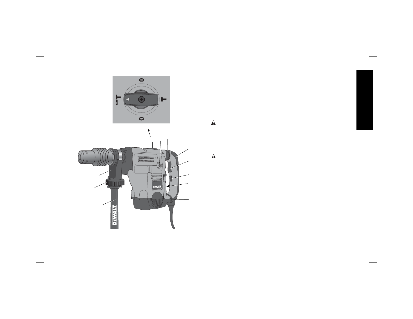
FIG. 1
HAMMERDRILLING
MODE
J
H
C
CHISEL BIT ADJUSTMENT MODE
CHISEL BIT ADJUSTMENT MODE
I
F
D25602
CHIPPING
MODE
E
INTENDED USE
These heavy-duty rotary hammers have been designed for
professional hammerdrilling, and chipping at various work sites
(i.e., construction sites). DO NOT use under wet conditions or in
English
presence of flammable liquids or gases.
This heavy-duty rotary hammer is a professional power tool. DO
NOT let children come into contact with the tool. Supervision is
required when inexperienced operators use this tool.
ASSEMBLY AND ADJUSTMENTS
WARNING: To reduce the risk of injury, turn unit off and
disconnect machine from power source before installing and
removing accessories, before adjusting or changing set-ups or
when making repairs. Be sure the trigger switch is in the OFF
D
A
B
G
E
position. An accidental start-up can cause injury.
Side Handle (Fig. 1)
WARNING: To reduce the risk of personal injury, ALWAYS
operate the tool with the side handle properly installed and securely
tightened. Failure to do so may result in the side handle slipping
during tool operation and subsequent loss of control. Hold tool with
both hands to maximize control.
The side handle clamps to the front barrel (collar) and may be rotated
360° to permit right or left-hand use. For operating convenience, the
side handle can be installed in front or rear positions.
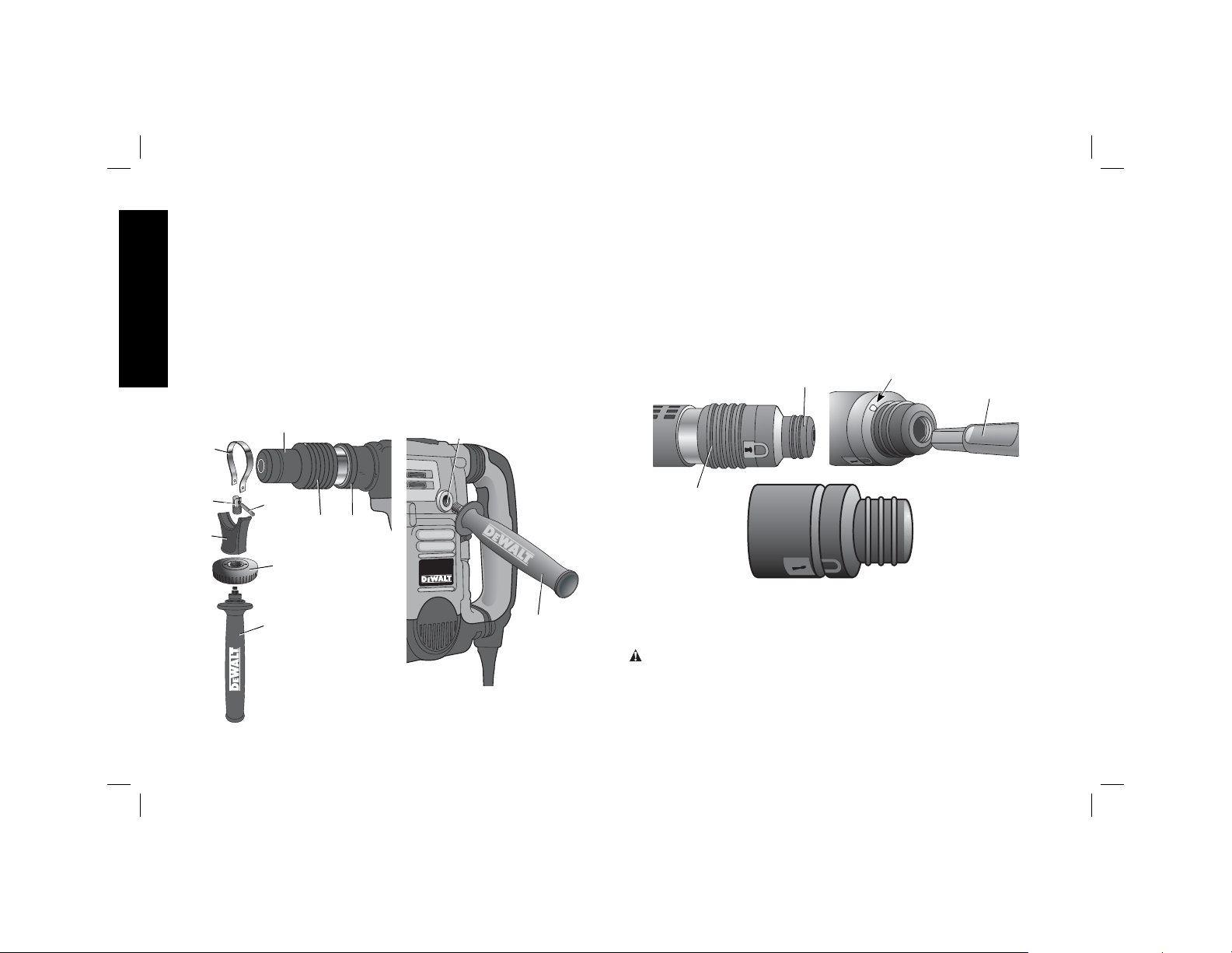
TO MOUNT IN FRONT POSITION (FIG. 2)
1. Unscrew the side handle (C) and disassemble the side handle
clamp (J).
2. Snap the steel ring (K) over the collar (L) behind the tool holder
(M). Squeeze both ends of the steel ring together. Mount the
bushing (N) and insert the pin (O).
3. Slide the side handle clamp (J) over the bushing and screw on
the clamp knob (H) –do not tighten.
4. Screw the side handle (C) into the clamp knob (H) and tighten.
5
Page 7
5. Rotate the side handle mounting assembly to the desired
position. For hammerdrilling horizontally with a heavy drill bit,
place the side handle assembly at an angle of approximately
20° to the tool for optimum control.
6. Lock the side handle mounting assembly in place by tightening
the clamp knob (H).
TO MOUNT IN REAR POSITION (FIG. 3)
English
1. Unscrew the side handle (C) and remove it from the side handle
mounting assembly. Leave the side handle mounting assembly
in the front position.
2. Screw the side handle directly into one of the rear side handle
positions (I) on either side of the tool.
FIG. 2
K
M
FIG. 3
I
Active Vibration Control (Fig. 1)
D25602, D25831, D25851
For best vibration control, hold the tool with one hand on the main
handle (D) and the other hand on the side handle (C). Apply just
enough pressure so the damping device on the main handle is
approximately midstroke. The hammer only needs enough pressure
to engage the active vibraton control. Applying too much pressure
will not make the tool drill or chip faster and active vibration control
will not engage.
FIG. 4
M
R
Q
N
J
O
P
L
H
P
Inserting and Removing Spline Drive
C
C
Accessories (Fig. 4)
D25851
WARNING: To reduce the risk of serious personal injury,
turn tool off and disconnect tool from power source before
making any adjustments or removing/installing attachments
or accessories.
1. Insert the bit shank into the tool holder (M) as far as it will go.
The groove on the chisel shank (Q) must be aligned with the
6
Page 8
symbol (R) on the toolholder. If inserted correctly,the locking
sleeve (P) moves back to the end position and shows a closed
lock symbol.
2. Pull on the bit to be sure that it is properly locked.
3. If the chisel groove is not aligned with the symbol, or is not
inserted to the complete depth the lock symbol remains open.
To remove the bit, pull back the locking sleeve and pull the bit out.
Inserting and Removing SDS Max®
Accessories
D25501, D25602, D25831
WARNING: To reduce the risk of serious personal injury,
turn tool off and disconnect tool from power source before
making any adjustments or removing/installing attachments
or accessories.
1. Pull back the locking sleeve (P) and insert the bit shank. The bit
shank must be clean.
2. Turn the bit slightly until the sleeve snaps back into position.
3. Ensure the bit is properly engaged.
NOTE: The bit needs to move several centimeters in and out of
the tool holder (M) when properly engaged.
4. To remove the bit, pull back the locking sleeve and pull the bit
out.
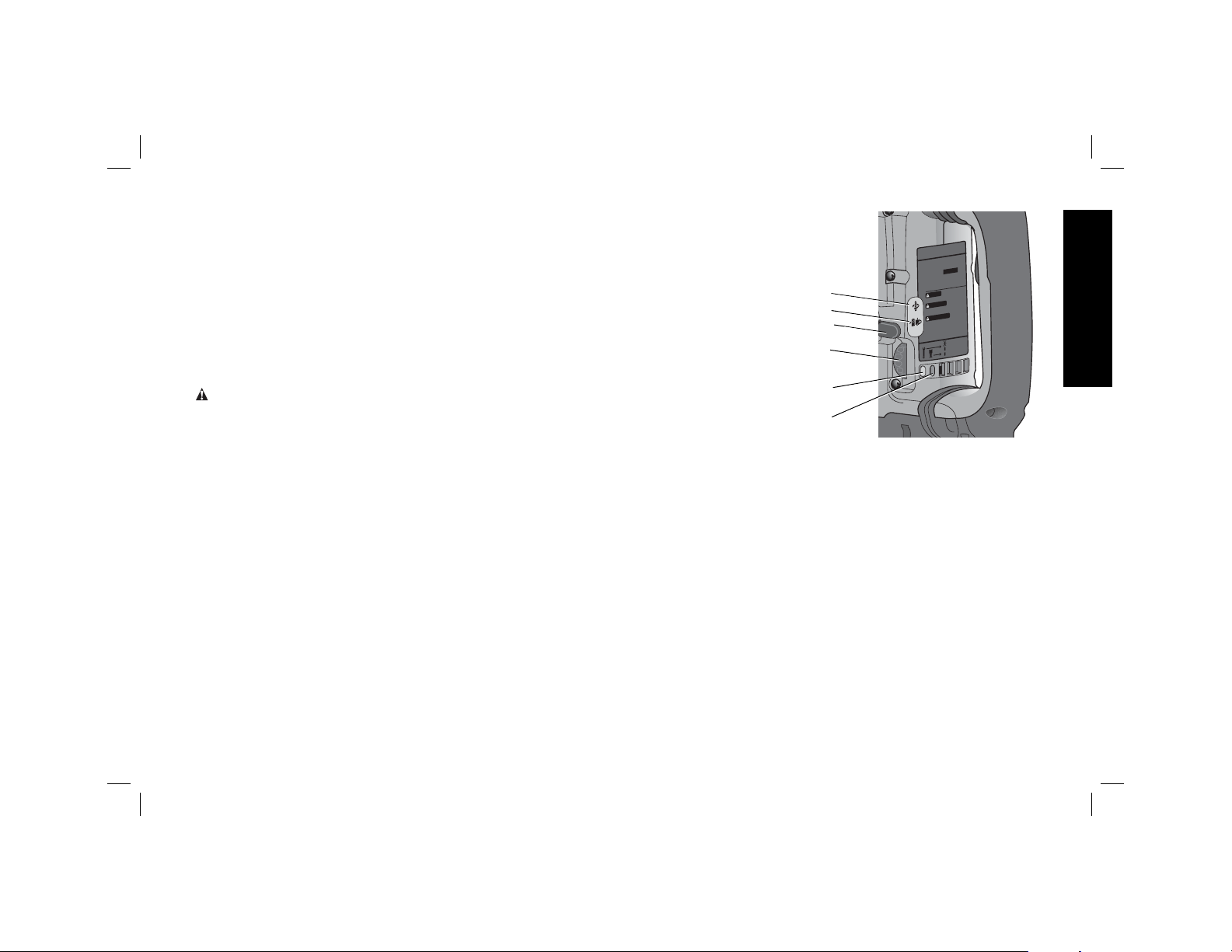
Complete Torque Control (Fig. 5)
D25602
NOTICE: Always turn the tool off before changing torque control
settings or damage to tool may result.
The Complete Torque Control (CTC) feature of this tool is designed
to provide additional control with a two-stage clutch mechanism.
Clutch Setting 1 (S) is designed for most hammerdrilling applications
and is designed to easily clutch out when the drill bit encounters
re-bar or other foreign substances.
Clutch Setting 2 (T) is
FIG. 5
designed for higher torque
applications such as corebits and deep hole
hammerdrilling and is
designed to clutch out at a
higher torque threshold.
Move the torque control
lever (U) to setting 1 or 2
as needed for application.
NOTE: Allow the motor
housing to rotate a little
S
T
U
G
V
COMPLETE TORQUE CONTROL
CTC
1 3/4" (44mm) SDS MAX
ROTARY HAMMER
D25XXX
SER.
TO REDUCE THE RISK OF INJUR
WARNING
USER MUST READ INSTRUCTION
YS USE PROPER EYE, EAR AND
LWA
LW
MANUAL. A
RY PROTECTION. A
ATO
RESPIR
LEA EL MANUAL DE
ADVERTENCIA
INSTRUCCIONES PARA
PARA LOS OJOS, OÍDOS Y VÍAS
UN FUNCIONAMIENTO SEGURO. SIEMPRE UTILICE
PROTECCIÓN ADECUADA
TORIAS. SIEMPRE UTILICE EL MANGO LATERAL.
A
RESPIR
1
AFIN DE MINIMISER
AVERTISSEMENT
TEUR DOIT LIRE LE GUIDE
LES RISQUES DE
A
’UTILIS
L
BLESSURES,
TION.TOUJOURS UTILISER UNE PROTECTION
A
D’UTILIS
AUDITIVE ET RESPIR
TÉRALE.
A
OCULAIRE,
2
UTILISER LA POIGNÉE L
T INDUSTRIAL TOOL CO., BA
L
A
W
E
TION, CALL 1-800-4-D
D
FOR SERVICE INFORMA
.com
T
L
A
W
E
.D
w
ww
YS USE SIDE HANDLE.
A
TOIRE ADÉQU
A
TIMORE, MD 21286 USA
L
T
L
A
W
E
Service
Lock-On
rvice
ush Se
r
B
Y,
TE.
A
while changing torque.
Each time the tool
W
is plugged in, it will
automatically default to
clutch setting 1, the most
sensitive setting.
Electronic Speed and Impact Control
(Fig. 5)
D25602, D25831, D25851
The electronic speed and impact control allows the use of smaller
drill bits without the risk of bit breakage, hammerdrilling into light
and brittle materials without shattering and optimal tool control for
precise chipping.
To set the control dial, turn the dial (G) to the desired level. The
higher the number, the greater the speed and impact energy. Dial
settings make the tool extremely adaptable for many different
appli cations. The required setting depends on the bit size and
hardness of material being drilled.
English
7
Page 9

Mode Selector (Fig. 1)
CAUTION: Never change the mode while the unit is running.
CAUTION: Do not change to hammerdrill mode with chisel bit in
tool holder. Personal injury and damage to tool may result.
The D25501, D25553, D25601, D25602 uses two operating modes.
To select the required operating mode, rotate the mode selector (F)
until the arrow points to the hammerdrilling or the chipping icon. The
English
D25831 uses only the chipping mode.
HAMMERDRILLING MODE (
The tool simultaneously rotates and impacts the work. This mode is
appropriate for all concrete and masonry operations.
CHIPPING MODE (
The spindle lock is engaged during chipping mode so the tool
impacts the work without rotating. This mode is appropriate for
light chipping, chiseling and demolition applications.
NOTE: In chipping mode, the hammerdrill can also be used as a
lever to free a jammed drill bit.
CHISEL BIT ADJUSTMENT (
Turn the mode selector to one of the chisel bit adjustment icons
to adjust the chisel to the desired position. There are 18 possible
positions to set the angle of the chisel. After finding the desired
position, slightly maneuver the chisel bit back and forth to ensure
the chisel is properly engaged.
)
)
)
Power Indicator Lights (Fig. 5)
The yellow brushwear indicator LED (V) lights up when the carbon
brushes are nearly worn out indicating that the tool needs servicing
within the next 8 hours of use.
The red indicator LED (W) lights up if the lock-on slider (B) is used
in any mode except the chipping mode.
The red indicator LED (W) flashes if there is a fault with the tool
or if the brushes are completely worn (refer to Brushes under
Maintenance).
OPERATION
WARNING: Always observe the safety instructions and applicable
regulations.
WARNING: To reduce the risk of serious personal injury,
turn tool off and disconnect tool from power source before
making any adjustments or removing/installing attachments
or accessories.
WARNING: To reduce the risk of personal injury, ALWAYS
ensure workpiece is anchored or clamped firmly. If drilling thin
material, use a wood “back-up” block to prevent damage to the
material.
WARNING: To reduce the risk of personal injury, ALWAYS
operate the tool with the side handle properly installed and
securely tightened. Failure to do so may result in the side handle
slipping during tool operation and subsequent loss of control. Hold
tool with both hands to maximize control.
Proper Hand Position (Fig. 1)
WARNING: To reduce the risk of serious personal injury,
ALWAYS use proper hand position as shown.
WARNING: To reduce therisk of serious personal injury, ALWAYS
hold securely in anticipation of a sudden reaction.
Proper hand position requires one hand on the side handle (C), with
the other hand on the main handle (D).
NOTE: Operating temperature of this tool is 19˚ to 104˚ F (-7
to +40˚ C). Using the tool outside of this temperature range will
decrease the life of the tool.
Trigger Switch (Fig. 1)
To turn the tool on, depress the trigger switch (A). To stop the tool,
release the trigger switch.
8
Page 10

D25602
In chipping mode only, lock the trigger switch on, push the lock-on
slider (B) upwards while depressing the trigger switch.
To deactivate the lock-on slider, depress the trigger switch once
then release.
The lock-on slider may only be activated in chipping mode. The
machine will stop running when trying to engage the lock-on slider
in hammerdrilling mode. The motor will stop if the lock-on slider is
activated when changing from chisel mode into hammerdrilling
mode.
D25831, D25851
For continuous operation, move the toggle switch to the on position.
To stop continuous operation, move the toggle switch to the off
position.
SOFT START FEATURE
The soft start feature allows you to build up speed slowly, thus
preventing the drill bit from walking off the intended hole position
when starting. The soft start feature also reduces the immediate
torque reaction transmitted to the gearing and the operator if the
hammer is started with the drill bit in an existing hole.
Hammerdrilling with a Solid Bit
D25501, D25601, D25602
NOTE: The D25831, D25851 has only chipping modes with no
hammerdrilling capability.
1. Set the mode selector (F) to hammerdrilling mode.
2. For D25602 only, move the torque control lever (U) to Setting 1
(S).
3. Set the speed and impact control dial (G).
4. Insert the appropriate drill bit.
5. Adjust the side handle (front or rear position) (C).
6. Mark the spot where the hole is to be drilled.
7. Place the drill bit on that mark and depress the trigger switch
(A).
8. Apply only enough pressure to engage active vibration control
(refer to Active Vibration Control).
9. To stop the tool, release the trigger switch. Always turn the tool
off when work is finished and before unplugging.
Hammerdrilling with a Core Bit
D25501, D25601, D25602
CAUTION: Do not use a core bit for hammerdrilling wood.
Personal injury and damage to tool may result.
NOTE: The D25831, D25851 has only chipping modes with no
hammerdrilling capability.
1. Set the mode selector (F) to hammerdrilling mode.
2. For D25602 only, move the torque control lever (U) to Setting 2
(T).
3. Turn the speed and impact control dial (G) to the maximum
speed (level 7).
4. Adjust the side handle (front or rear position) (C).
5. Assemble the centering bit and adapter shank into core bit.
6. Mark the spot where the hole is to be drilled.
7. Place the centering bit on that mark and depress the trigger
switch (A).
NOTE: Some core drills require the removal of centering bit
after about 1 cm of penetration. If so, remove and continue
hammerdrilling.
8. When hammerdrilling through a structure thicker than the
depth of the core bit, break away the round cylinder of
concrete or core inside the bit at regular intervals. To avoid
unwanted breaking away of concrete around the hole, first drill
English
9
Page 11

a hole the diameter of the centering bit completely through the
structure. Then drill the cored hole halfway from each side of
the structure.
9. To stop the tool, release the trigger switch. Always turn the tool
off when work is finished and before unplugging.
Chipping
D25831, D25851
English
1. Set the mode selector (F) to chipping mode.
2. Set the impact control dial (G) to desired setting (refer to
Electronic Speed and Impact Control).
3. Insert the appropriate chisel and rotate it by hand to lock it into
the desired position.
NOTE: For SDS Max
4. Adjust the side handle (front or rear position) (C).
5. Depress the trigger switch (A).
6. Apply only enough pressure to engage active vibration control
(refer to Active Vibration Control).
7. To stop the tool, release the trigger switch. Always turn the tool
off when work is finished and before unplugging.
®
models, only use SDS Max® bits.
MAINTENANCE
Your DEWALT power tool has been designed to operate over a
long period of time with a minimum of maintenance. Continuous
satisfactory operation depends upon proper tool care and regular
cleaning.
WARNING: To reduce the risk of injury, turn unit off and
disconnect tool from power source before installing and removing
accessories, before making any adjustments or removing/installing
attachments or accessories.
Cleaning
WARNING: Blow dirt and dust out of all air vents with dry air at
least once a week. Wear proper ANSI Z87.1 (CAN/CSA Z94.3) eye
protection and proper NIOSH/OSHA/MSHA respiratory protection
when performing this.
WARNING: Never use solvents or other harsh chemicals for
cleaning the non-metallic parts of the tool. These chemicals may
weaken the plastic materials used in these parts. Use a cloth
dampened only with water and mild soap. Never let any liquid get
inside the tool; never immerse any part of the tool into a liquid.
Lubrication
Your tool was properly lubricated before leaving the factory. In from
two to six months, depending upon use, take or send your tool to
an authorized service center for a complete cleaning, inspection
and lubrication. Tools used constantly on production jobs will need
relubrication more often. Also, tools “out of service” for long periods
should be relubricated before being put back to work.
Accessories
WARNING: Since accessories, other than those offered by
D
EWALT, have not been tested with this product, use of such
accessories with this tool could be hazardous. To reduce the risk of
injury, only D
with this product.
Recommended accessories for use with your tool are available at
extra cost from your local dealer or authorized service center.
D25501 D25601 D25602 D25831
Concrete 1-9/16" 1-9/16" 1-3/4" –
(40 mm) (40 mm) (45 mm) –
RPM 490 490 210–415 –
No load BPM 3300 3300 1430–2840 1430–2840
EWALT, recommended accessories should be used
MAXIMUM CAPACITY
10
Page 12

Repairs
To assure product SAFETY and RELIABILITY, repairs, maintenance
and adjustment (including brush inspection and replacement)
should be performed by authorized service centers or other
qualified service personnel, always using identical replacement
parts.
English
D25501 D25601 D25602 D25831
Voltage: 120 V AC
Current 12 A 12 A 13.5 A 13.5 A
Frequency: 50–60 Hz 50–60 Hz 50–60 Hz 50–60 Hz
Watts 1100 W 1200 W 1200 W 1200 W
RPM: 490/min 210–415/min 210–415/min –
Beats per
minute (BPM) 3300 1430–2840 1430–2840 1430–2840 bpm
SPECIFICATIONS
120 V AC 120 V AC 120 V AC
11
Page 13

Definiciones: Normas
de seguridad
Las siguientes definiciones describen el nivel de gravedad de
cada advertencia. Lea el manual y preste atención a estos
símbolos.
PELIGRO:
no se evita,
ADVERTENCIA:
que, si no se evita,
graves
ATENCIÓN:
no se evita,
AVISO: Se refiere a una práctica
corporales
propiedad.
Español
ADVERTENCIA: para reducir el riesgo de lesiones, lea el
manual de instrucciones.
indica una situación de peligro inminente que, si
provocará
puede
que de no evitarse
la
muerte o lesiones graves.
Indica una situación de peligro potencial
podría
Indica una situación de peligro potencial que, si
provocar
provocar la
lesiones leves o moderadas.
puede resultar
muerte o lesiones
no relacionada a lesiones
en
daños a la
Advertencias generales de seguridad
para las herramientas eléctricas
ADVERTENCIA: Lea todas las advertencias de seguridad e
instrucciones.
instrucciones puede provocar descargas eléctricas, incendios o
lesiones graves.
GUARDE LAS ADVERTENCIAS E
INSTRUCCIONES PARA PODER
CONSULTARLAS EN EL FUTURO
El término “herramienta eléctrica” incluido en todas las advertencias
se refiere a su herramienta eléctrica conectada a la red (cable
eléctrico) o a su herramienta eléctrica accionada con baterías
(inalámbrica).
El incumplimiento de las advertencias o
1) SEGURIDAD DEL ÁREA DE TRABAJO
a) Mantenga el área de trabajo limpia y bien iluminada. Las
áreas abarrotadas u oscuras propician accidentes.
b) No haga funcionar las herramientas eléctricas en
atmósferas explosivas, como ambientes donde haya
polvo, gases o líquidos inflamables. Las herramientas
eléctricas originan chispas que pueden encender el polvo o
producir humo.
c) Mantenga alejados a los niños y a los espectadores de la
herramienta eléctrica en funcionamiento. Las distracciones
pueden provocar la pérdida de control.
2) SEGURIDAD ELÉCTRICA
a) Los enchufes de la herramienta eléctrica deben adaptarse
a la toma de corriente. Nunca modifique el enchufe de
ninguna manera. No utilice ningún enchufe adaptador
con herramientas eléctricas con conexión a tierra. Los
enchufes no modificados y que se adaptan a las tomas de
corrientes reducirán el riesgo de descarga eléctrica.
b) Evite el contacto corporal con superficies con toma de
tierra como, por ejemplo, tuberías, radiadores, cocinas y
refrigeradores. Existe mayor riesgo de descarga eléctrica si
su cuerpo está puesto a tierra.
c) No exponga las herramientas eléctricas a la lluvia ni a
condiciones de humedad. Si entra agua en una herramienta
eléctrica, aumentará el riesgo de descarga eléctrica.
d) No use el cable indebidamente. Nunca utilice el cable para
transportar, tirar o desenchufar la herramienta eléctrica.
Mantenga el cable alejado del calor, el aceite, los bordes
afilados o las piezas móviles. Los cables dañados o
enredados aumentan el riesgo de descarga eléctrica.
e) Al operar una herramienta eléctrica en el exterior, utilice
un cable prolongador adecuado para tal uso. Utilice un
cable adecuado para uso en exteriores a fin de reducir el
riesgo de descarga eléctrica.
12
Page 14

f) Si no se puede evitar el uso de una herramienta eléctrica
en una zona húmeda, utilice un dispositivo de corriente
residual (residual current device, RCD) de seguridad.
El uso de un RCD reduce el riesgo de sufrir una descarga
eléctrica.
3) SEGURIDAD PERSONAL
a) Permanezca alerta, controle lo que está haciendo y utilice el
sentido común cuando emplee una herramienta eléctrica.
No utilice una herramienta eléctrica si está cansado o
bajo el efecto de drogas, alcohol o medicamentos. Un
momento de descuido mientras se opera una herramienta
eléctrica puede provocar lesiones personales graves.
b) Utilice equipo de seguridad personal. Utilice siempre
protección ocular. El uso de equipo de seguridad, como
mascarillas para polvo, calzado de seguridad antideslizante,
cascos o protección auditiva en las condiciones adecuadas
reducirá las lesiones personales.
c) Evite poner en marcha la herramienta involuntariamente.
Asegúrese de que el interruptor está apagado antes de
conectar la fuente de alimentación y/o la batería, coger
o transportar la herramienta. Transportar herramientas
eléctricas con su dedo apoyado sobre el interruptor o
enchufar herramientas eléctricas con el interruptor en la
posición de encendido puede propiciar accidentes.
d) Retire la clavija de ajuste o la llave de tuercas antes de
encender la herramienta eléctrica. Una llave de tuercas
o una clavija de ajuste que quede conectada a una pieza
giratoria de la herramienta eléctrica puede provocar lesiones
personales.
e) No se estire demasiado. Conserve el equilibrio y
posiciónese adecuadamente en todo momento. Esto
permite un mejor control de la herramienta eléctrica en
situaciones inesperadas.
f) Use la vestimenta adecuada. No use ropas holgadas ni
joyas. Mantenga el cabello, la ropa y los guantes alejados
de las piezas en movimiento. Las ropas holgadas, las joyas
o el cabello largo pueden quedar atrapados en las piezas
en movimiento.
g) Si se suministran dispositivos para la conexión de
accesorios con fines de recolección y extracción de
polvo, asegúrese de que estén conectados y que se
utilicen correctamente. El uso del extractor de polvo puede
reducir los riesgos relacionados con el polvo.
4) USO Y MANTENIMIENTO DE LA HERRAMIENTA
ELÉCTRICA
a) No fuerce la herramienta eléctrica. Utilice la herramienta
eléctrica correcta para el trabajo que realizará. La
herramienta eléctrica correcta hará el trabajo mejor, y de un
modo más seguro, a la velocidad para la que fue diseñada.
b) No utilice la herramienta eléctrica si no puede encenderla
o apagarla con el interruptor. Las herramientas que no
puedan ser controladas con el interruptor constituyen un
peligro y deben repararse.
c) Desconecte el enchufe de la fuente de alimentación o
la batería de la herramienta eléctrica antes de realizar
cualquier ajuste, cambio de accesorios o almacenar
las herramientas eléctricas. Estas medidas de seguridad
preventivas reducen el riesgo de encender la herramienta
eléctrica de forma accidental.
d) Guarde la herramienta eléctrica que no esté en uso fuera
del alcance de los niños y no permita que otras personas
no familiarizadas con ella o con estas instrucciones
operen la herramienta. Las herramientas eléctricas son
peligrosas si son operadas por usuarios que no tienen
formación.
Español
13
Page 15

e) Mantenimiento de las herramientas eléctricas. Revise que
no haya piezas en movimiento mal alineadas o trabadas,
piezas rotas o cualquier otra situación que pueda afectar
el funcionamiento de las herramientas eléctricas. Si
encuentra daños, haga reparar la herramienta eléctrica
antes de utilizarla. Se producen muchos accidentes a
causa de las herramientas eléctricas que carecen de un
mantenimiento adecuado.
f) Mantenga las herramientas de corte afiladas y limpias.
Las herramientas de corte con mantenimiento adecuado y
con los bordes de corte afilados son menos propensas a
trabarse y son más fáciles de controlar.
g) Utilice las herramientas eléctricas, sus accesorios y
piezas, etc. de acuerdo con las presentes instrucciones,
teniendo siempre en cuenta las condiciones de trabajo y
el trabajo que deba llevar a cabo. El uso de la herramienta
eléctrica para operaciones diferentes de aquellas para las que
fue diseñada podría originar una situación peligrosa.
5) MANTENIMIENTO
Español
a) Solicite a una persona cualificada en reparaciones que
realice el mantenimiento de su herramienta eléctrica
y que solo utilice piezas de repuesto idénticas. Esto
garantizará la seguridad de la herramienta eléctrica.
Instrucciones de seguridad adicionales
para los rotomartillos
• Utilice protectores auditivos. La exposición a ruidos puede
causar pérdida auditiva.
• Utilice los mangos auxiliares que vienen con la herramienta.
Perder el control de la herramienta podría causar lesiones
corporales.
• Sostenga la herramienta eléctrica por sus superficies de
empuñadura aisladas cuando realice una operación en la
cual la herramienta para cortar pudiera entrar en contacto
con instalaciones eléctricas ocultas o con su propio
cable. El contacto con un conductor “activo” hará que las
piezas metálicas de la herramienta que estén expuestas a él
conduzcan electricidad y que el operador reciba una descarga
eléctrica.
• Use abrazaderas u otra manera práctica de fijar y sujetar la
pieza de trabajo a una plataforma estable. Sujetar la pieza
con la mano o contra el cuerpo es inestable y resultará en que
pierda el control.
• Lleve lentes de seguridad u otra protección ocular. Las
operaciones de martilleo provocan la expulsión de virutas. Las
partículas despedidas pueden provocar lesiones irreversibles en
los ojos. Lleve una mascarilla antipolvo o un respirador cuando
realice aplicaciones que generen polvo. En la mayoría de las
aplicaciones puede ser necesaria una protección auditiva.
• Mantenga siempre la herramienta bien sujeta. No opere la
herramienta si no puede sujetarla con ambas manos. Es
recomendable usar siempre el mango lateral. Si opera esta
herramienta con una sola mano, perderá el control de la misma.
Atravesar o topar con materiales duros, tales como un refuerzo
posterior, también podría resultar peligroso. Ajuste bien el
mango lateral antes de usar la herramienta.
• No opere esta herramienta durante períodos largos de
tiempo. La vibración provocada por la acción de percusión
puede ser peligrosa para sus manos y brazos. Utilice guantes
para mayor amortiguación y descanse con frecuencia para
limitar el riesgo de exposición.
• No renueve las brocas usted mismo. La renovación de las
brocas debe realizarla un especialista autorizado. Una broca
mal renovada puede provocar lesiones.
• Lleve guantes al operar la herramienta y al cambiar las
brocas. Las piezas metálicas de la herramienta y las brocas
14
Page 16

pueden calentarse mucho durante la operación. Los pequeños
trozos de material roto pueden dañar las manos desprotegidas.
• Nunca suelte la herramienta hasta que la broca haya
dejado de girar totalmente. Las brocas en movimiento pueden
provocar lesiones.
• Si una broca se atasca, no la golpee con un martillo para
desbloquearla. Podrían saltar fragmentos de metal o virutas de
material y provocar lesiones.
• Las brocas ligeramente desgastadas pueden afilarse de
nuevo.
NOTA: No sobrecaliente la broca (decoloración) mientras la afila
de nuevo. Las brocas muy gastadas precisan un reforjado. No
reendurezca ni temple la broca.
• Mantenga el cable alejado de la broca en movimiento. No
enrolle el cable alrededor de ninguna parte de su cuerpo.
Un cable eléctrico enrollado alrededor de una broca que gira
puede provocar lesiones y pérdida de control.
• Los orificios de ventilación suelen cubrir piezas en
movimiento, por lo que también se deben evitar. Las partes
móviles pueden atrapar las prendas de vestir sueltas, las joyas
y el cabello.
• Los hilos del alargador deben ser de un calibre apropiado
para su seguridad. Un cable de un calibre insuficiente causará
una caída en la tensión de la línea dando por resultado una
pérdida de energía y sobrecalentamiento. Cuando se utilice más
de un alargador para completar el largo total, asegúrese que
los hilos de cada alargador tengan el calibre mínimo. La tabla
siguiente muestra el tamaño correcto a utilizar, dependiendo
de la longitud del cable y del amperaje nominal de la placa de
identificación. Si tiene dudas sobre cuál calibre usar, use un
calibre mayor.
Ténsion (Volts) Longitud del cable en metros (m)
120 - 127V 0 - 7 7 - 15 15 - 30 30 - 50
220 - 240V 0 - 15 15 - 30 30 - 60 60 - 100
Corriente
nominal
(Ampéres)
0 - 6A 1,0 1,5 1,5 2,5
6 - 10A 1,0 1,5 2,5 4,0
10 - 12A 1,5 1,5 2,5 4,0
12 - 16A 2,5 4,0 No recomendado
ADVERTENCIA: Siempre use protección ocular. Todos los
usuarios y personas circunstantes deben llevar protección ocular
en conformidad con ANSI Z87.1.
ADVERTENCIA: Siempre lleve la debida protección auditiva
personal en conformidad con ANSI S12.6 (S3.19) durante el
uso de esta herramienta. Bajo algunas condiciones y duraciones
de uso, el ruido producido por este producto puede contribuir a la
pérdida auditiva.
ADVERTENCIA: Use SIEMPRE lentes de seguridad. Los
anteojos de uso diario NO son lentes de seguridad. Utilice también
máscaras faciales o para polvo si los cortes producen polvillo.
UTILICE SIEMPRE EQUIPOS DE SEGURIDAD CERTIFICADOS:
• Protección para los ojos ANSI Z87.1 (CAN/CSA Z94.3),
• Protección auditiva ANSI S12.6 (S3.19),
• Protección respiratoria según las normas NIOSH/OSHA/
MSHA.
ADVERTENCIA: Parte del polvo creado al lijar, aserruchar,
moler o perforar con máquina, así como al realizar otras actividades
de la construcción, contiene substancias químicas que se sabe
producen cáncer, defectos congénitos u otras afecciones
reproductivas. Algunos ejemplos de esas substancias químicas
son:
• plomo de pinturas a base de plomo,
Sección nominal mínima del cable en
milímetros cuadrados (mm2 )
Español
15
Page 17

• sílice cristalizado de ladrillos y cemento y otros productos de
albañilería, y
• arsénico y cromo de la madera químicamente tratada (CCA).
El riesgo al contacto con estas substancias varía, según la
frecuencia en que se haga este tipo de trabajo. Para reducir la
exposición a esas substancias químicas: trabaje en un área bien
ventilada, y trabaje con equipos de seguridad aprobados, tales
como máscaras contra el polvo especialmente diseñadas para filtrar
las partículas microscópicas.
• Evite el contacto prolongado con polvos originados por lijar,
aserrar, esmerilar, taladrar y otras actividades constructivas.
Vista ropas protectoras y lave las áreas expuestas con agua
y jabón. Permitir que el polvo se introduzca en su boca, ojos,
o dejarlo sobre la piel promueve la absorción de químicos
dañinos.
ADVERTENCIA: La utilización de esta herramienta puede
originar polvo o dispersarlo, lo que podría causar daños graves y
permanentes al sistema respiratorio, así como otras lesiones.
Siempre use protección respiratoria aprobada por NIOSH/OSHA,
Español
apropiada para su uso en condiciones de exposición al polvo.
Procure que las partículas no se proyecten directamente sobre su
rostro o su cuerpo.
• La etiqueta de la herramienta puede incluir los siguientes
símbolos. A continuación se indican los símbolos y sus
definiciones:
V ......... voltios A ...........amperios
Hz ....... hertz W ..........vatios
min ...... minutos
... corriente directa .........corriente alterna o
........ Construcción Clase I .............. directa
........... (con conexión a tierra) no ..........velocidad sin carga
......... corriente alterna
........ Construcción Clase II ..........terminal a tierra
............ (con aislamiento doble) ..........símbolo de alerta de
…/min . por minuto
IPM .....impactos por minutos GPM .....golpes por minuto
RPM .... revoluciones o
reciprocidad por
minuto
.............. seguridad
Motor
Esta herramienta DEWALT está impulsada por un motor fabricado
por D
EWALT. Compruebe que el suministro eléctrico concuerde
con el indicado en la placa de características. Una reducción
del voltaje superior al 10% provocará pérdida de potencia y
sobrecalentamiento. Todas las herramientas D
de fábrica.
EWALT se prueban
DESCRIPCIÓN (Fig. 1)
ADVERTENCIA: Nunca modifique la herramienta eléctrica ni
ninguna pieza de esta. Puede producir daños o lesiones corporales.
A. Interruptor de gatillo G. Selector de control
B. Pieza deslizante de bloqueo electrónico de la velocidad
C. Agarradera lateral y el impacto
D. Agarradera principal H. Perilla de soporte
E. Control de vibración activa I. Posición trasera de la
agarradera lateral
F. Selector de modalidad
USO DEBIDO
Estos rotomartillos para trabajos pesados han sido diseñados
para el taladrado con percusión y corte por capas realizado a
nivel profesional en diversos sitios de trabajo (por ejemplo, sitios
de construcción). NO utilice la herramienta en condiciones de
humedad o en la presencia de líquidos o gases inflamables.
16
Page 18

Este rotomartillo es una herramienta eléctrica profesional. NO
permita que los niños toquen la herramienta. Si el operador no
tiene experiencia operando esta herramienta, su uso deberá ser
supervisado.
FIG. 1
MODO TALADRO
PERCUTOR
MODO DE AJUSTE DE LA BROCA DE CINCEL
MODO DE AJUSTE DE LA BROCA DE CINCEL
F
J
H
C
MODO
CINCEL
E
I
D
A
B
G
E
D25602
MONTAJE Y AJUSTES
ADVERTENCIA: Para reducir el riesgo de lesiones, apague y
desconecte la máquina de la fuente de energía antes de
instalar y de retirar los accesorios, antes de regular o cambiar
los ajustes o cuando se realicen reparaciones. Compruebe que
el interruptor esté en la posición OFF. Un encendido accidental
puede causar lesiones.
Mango lateral (Fig. 1)
ADVERTENCIA: Para reducir el riesgo de lesiones corporales,
SIEMPRE opere la herramienta con el mango lateral debidamente
instalado y ajustado. El incumplimiento con lo anterior podría
resultar en que el mango lateral se suelte durante la operación
de la herramienta y que el operador pierda el control como
consecuencia. Sostenga la herramienta con ambas manos para
maximizar control.
La agarradera lateral se sujeta al cilindro frontal (collarín) y se
puede girar 360° para permitir su uso con la mano derecha o
izquierda. Para mayor comodidad, la agarradera lateral puede
montarse en las posiciones delantera o trasera.
MONTAJE EN LA POSICIÓN DELANTERA (FIG. 2)
1. Desatornille la agarradera lateral (C) y desmonte el soporte de
la agarradera lateral (J).
2. Cierre el anillo de acero (K) sobre el collarín (L) situado detrás
del portaherramientas (M). Apriete ambos extremos del anillo
de acero uno contra el otro. Monte el casquillo (N) e inserte la
clavija (O).
3. Deslice la abrazadera de la agarradera lateral (J) sobre el
casquillo y atornille sobre la perilla de soporte (H); no apriete.
4. Atornille la agarradera lateral (C) en la perilla de soporte (H) y
apriete.
Español
17
Page 19

5. Haga girar el conjunto de montaje de la agarradera lateral
hasta la posición deseada. Si debe taladrar con percusión
horizontalmente con una broca para trabajos pesados, para
lograr un control óptimo coloque el conjunto de la agarradera
con un ángulo de unos 20° respecto a la herramienta.
6. Fije en su sitio el conjunto de montaje de la agarradera lateral
apretando la perilla de soporte (H).
FIG. 2
K
N
J
M
O
P
H
FIG. 3
L
I
Español
C
MONTAJE EN LA POSICIÓN TRASERA (FIG. 3)
1. Desatornille la agarradera lateral (C) y retírela del conjunto de
montaje de la agarradera lateral. Deje el conjunto de montaje
de la agarradera lateral en la posición frontal.
2. Atornille la agarradera lateral directamente en una de las
posiciones traseras (I) situadas a uno y otro lado de la
herramienta.
Control de vibración activa (Fig. 1)
D25602, D25831, D25851
Para un mejor control de la vibración, sostenga la herramienta
con una mano en la agarradera principal (D) y la otra en la
agarradera lateral (C). Aplique solamente suficiente presión para
que el dispositivo amortiguador sobre la agarradera principal
quede aproximadamente a la mitad de su recorrido. El martillo sólo
requiere una cantidad suficiente de presión para activar el control
de vibración activa. La herramienta no taladrará ni cortará con
mayor rapidez, ni se activará el control de vibración activa si se
aplica más presión de la necesaria.
FIG. 4
C
P
M
R
Q
Inserción y desmontaje de accesorios
estriados (Fig. 4)
D25851
ADVERTENCIA: Para reducir el riesgo de lesiones corporales
graves, apague la herramienta y desconéctela de la fuente
de alimentación antes de realizar ajustes o de quitar o poner
accesorios.
18
Page 20

1. Inserte el vástago de la broca en el portaherramientas (M) tanto
como pueda. El surco sobre el vástago del cincel (Q) debe estar
alineado con el símbolo (R) sobre el portaherramientas. Si está
insertado correctamente, el manguito de bloqueo (P) retrocede
a la posición extrema y muestra un símbolo de candado
cerrado.
2. Tire de la broca para comprobar que esté bien sujeta.
3. Si el surco del cincel no está alineado con el símbolo, o no está
completamente insertado, el símbolo de candado permanece
abierto.
Para retirar la broca, tire del manguito de bloqueo y extraiga la
broca.
Inserción y desmontaje de accesorios
SDS Max
D25501, D25602, D25831
ADVERTENCIA: Para reducir el riesgo de lesiones corporales
graves, apague la herramienta y desconéctela de la fuente de
alimentación antes de realizar ajustes o de quitar o poner
accesorios.
1. Tire hacia atrás del manguito de bloqueo (P) e inserte el
vástago de la broca. El vástago de la broca debe estar limpio.
2. Gire ligeramente la broca hasta que el manguito vuelva a su
posición.
3. Cerciórese que la broca esté engranada en forma apropiada.
NOTA: La broca necesita moverse varios centímetros adentro
y afuera del portaherramientas (M) cuando está engranado en
forma apropiada.
4. Para retirar la broca, tire del manguito de bloqueo y extraiga la
broca.
®
Control completo del par de torsión
(Fig. 5)
D25602
AVISO: Siempre apague la herramienta antes de cambiar los
ajustes de control del par de torsión o podría dañar la herramienta.
La función de Control completo del par de torsión (CTC) de esta
herramienta está diseñada para proporcionar control adicional
con un mecanismo de embrague en dos etapas.
La configuración de embrague 1 (S) está orientada a la mayoría
de aplicaciones de taladrado de percusión y está diseñada para
desembragar fácilmente cuando la broca encuentre varillas de
refuerzo u otras sustancias extrañas.
La configuración de
embrague 2 (T) está
orientada a aplicaciones
con mayor par de
torsión, tales como
barrenas huecas y
taladrado de percusión
de orificios profundos, y
está diseñada para
FIG. 5
S
T
U
G
COMPLETE TORQUE CONTROL
CTC
1 3/4" (44mm) SDS MAX
TARY HAMMER
RO
D25XXX
SER.
TO REDUCE THE RISK OF INJUR
WARNING
USER MUST READ INSTRUCTION
YS USE PROPER EYE, EAR AND
LWA
LW
MANUAL. A
RY PROTECTION. A
ATO
RESPIR
LEA EL MANUAL DE
ADVERTENCIA
INSTRUCCIONES PARA
PARA LOS OJOS, OÍDOS Y VÍAS
UN FUNCIONAMIENTO SEGURO. SIEMPRE UTILICE
PROTECCIÓN ADECUADA
TORIAS. SIEMPRE UTILICE EL MANGO LATERAL.
A
RESPIR
1
AFIN DE MINIMISER
AVERTISSEMENT
TEUR DOIT LIRE LE GUIDE
LES RISQUES DE
A
’UTILIS
L
BLESSURES,
TOUJOURS UTILISER UNE PROTECTION
TION.
A
D’UTILIS
AUDITIVE ET RESPIR
TÉRALE.
A
OCULAIRE,
2
UTILISER LA POIGNÉE L
T INDUSTRIAL TOOL CO., BA
L
A
W
E
TION, CALL 1-800-4-D
D
FOR SERVICE INFORMA
.com
T
L
A
W
E
.D
w
ww
YS USE SIDE HANDLE.
A
TOIRE ADÉQU
A
TIMORE, MD 21286 USA
L
T
L
A
W
E
Service
Lock-On
rvice
ush Se
r
B
Y,
TE.
A
desembragar al pasar
un mayor umbral de par
de torsión.
Desplace la palanca de
control del par de torsión
V
W
(U) a la configuración 1 ó 2 según lo requiera la aplicación.
NOTA: Permita que la carcasa del motor gire un poco al cambiar
el par de torsión.
Cada vez que se enchufa la herramienta se pondrá
automáticamente en la configuración de embrague 1, la
configuración más sensible.
Español
19
Page 21

Control electrónico de la velocidad y el
impacto (Fig. 5)
D25602, D25831, D25851
El control electrónico de la velocidad y el impacto permite usar
brocas más pequeñas sin riesgo de romperlas; taladrar con
percusión en materiales ligeros y frágiles sin astillarlos, y tener un
control óptimo para un burilado preciso.
Para fijar el selector de control, gire el selector (G) al nivel
deseado. Cuanto más alto sea el número, mayores serán la
velocidad y la energía de impacto. Los valores del selector
permiten que la herramienta resulte extremadamente adaptable
para muchas aplicaciones diversas. El valor adecuado depende
del tamaño de la broca y la dureza del material taladrado.
Selector de modo (Fig. 1)
ATENCIÓN: Nunca cambie el modo mientras que la unidad esté
funcionando.
Español
ATENCIÓN: No cambie a la modalidad de taladro percutor con la
broca para cincelado en el portaherramientas. Podrían presentarse
lesiones corporales y daños a la herramienta.
Los D25501, D25553, D25601, D25602 utilizan dos modos
operativos. Para seleccionar el modo operativo requerido, gire el
selector de modalidad (F) hasta que la flecha apunte al ícono de
taladrado de percusión o de burilado. El D25831 solamente utiliza
el modo de burilado.
MODO DE TALADRADO DE PERCUSIÓN (
La herramienta gira e impacta el trabajo simultáneamente. Este
modo es adecuado para todas las operaciones sobre hormigón y
mampostería.
MODO DE BURILADO (
El seguro del eje está engranado durante el modo de burilado de
tal modo que la herramienta impacta el trabajo sin rotación. Este
)
)
modo es adecuado para trabajos livianos de burilado, cincelado
y demolición.
NOTA: En modo de burilado, el taladro percutor también puede
usarse como palanca para liberar una broca atascada.
AJUSTE DE LA BROCA PARA CINCELADO ( )
Gire el selector de modalidad hasta uno de los íconos de ajuste
de la broca para cincelado para ajustar el cincel a la posición
deseada. Existen 18 posiciones posibles para ajustar el ángulo
del cincel. Después de encontrar la posición deseada, maniobre
suavemente la broca para cincelado hacia atrás y hacia adelante
para cerciorarse de que el cincel esté engranado en forma
apropiada.
Luces indicadoras de energía (Fig. 5)
El indicador LED amarillo del desgaste de escobillas (V) se
enciende cuando las escobillas de carbón estén casi desgastadas,
indicando que la herramienta necesita servicio dentro de las
próximas 8 horas de uso.
El indicador LED rojo (W) se enciende si la pieza deslizante de
bloqueo (B) es utilizada en cualquier modo distinto al modo de
burilado.
El indicador LED rojo (W) destella si se presenta una avería en la
herramienta, o si las escobillas están completamente desgastadas
(refiérase a Escobillas bajo Mantenimiento).
FUNCIONAMIENTO
ADVERTENCIA: Respete siempre las instrucciones de seguridad
y la reglamentación aplicable.
ADVERTENCIA: Para reducir el riesgo de lesiones corporales
graves, apague la herramienta y desconéctela de la fuente de
alimentación antes de realizar ajustes o de quitar o poner
accesorios.
20
Page 22

ADVERTENCIA: Para reducir el riesgo de lesiones
corporales, SIEMPRE asegúrese de que la pieza de trabajo
esté debidamente sujeta. Si va a perforar un material delgado,
utilice un bloque de madera como “respaldo” para evitar dañarlo.
ADVERTENCIA: Para reducir el riesgo de lesiones
corporales, SIEMPRE opere la herramienta con el mango
lateral debidamente instalado y ajustado. El incumplimiento con
lo anterior podría resultar en que el mango lateral se suelte durante
la operación de la herramienta y que el operador pierda el control
como consecuencia. Sostenga la herramienta con ambas manos
para maximizar control.
Bien colocar las manos (Fig. 1)
ADVERTENCIA: Para reducir el riesgo de lesiones personales,
SIEMPRE coloque bien las manos, tal como se muestra.
ADVERTENCIA: Para reducir el riesgo de lesiones personales,
SIEMPRE debe de sujetar la herramienta correctamente para
anticipar reacciones súbitas.
Mantenga una mano sobre el mango lateral (C) y la otra sobre el
mango principal (D) para sujetar la máquina correctamente.
NOTA: La temperatura de operación de esta herramienta es -7 a
+40 ˚C (19˚ a 104 ˚F). El utilizar la herramienta por fuera de este
rango de temperatura disminuirá la vida útil de la herramienta.
Interruptor de gatillo (Fig. 1)
Para encender la herramienta, apriete el interruptor de gatillo (A).
Para detener la herramienta, suelte el interruptor de gatillo.
D25602
Sólo en el modo de burilado, bloquee el interruptor de gatillo,
empuje la pieza deslizante de bloqueo (B) hacia arriba mientras
presiona el interruptor de gatillo.
Para desactivar la pieza deslizante de bloqueo, presione una vez
el interruptor de gatillo y suelte a continuación.
La pieza deslizante de bloqueo solamente puede ser activada
en el modo de burilado. La máquina dejará de operar cuando se
intente engranar la pieza deslizante de bloqueo en el modo de
taladrado de percusión. El motor se detendrá si la pieza deslizante
para bloqueo en encendido es activada al cambiar del modo de
cincelado al modo de taladrado de percusión.
D25831, D25851
Para operación continua, desplace el conmutador basculante a
la posición de encendido. Para detener la operación continua,
desplace el conmutador basculante a la posición de apagado.
FUNCIÓN DE ARRANQUE PROGRESIVO
La función de arranque progresivo permite aumentar la velocidad
lentamente, de modo que la broca no se mueva de la posición de
taladrado al arrancar. La función de arranque progresivo también
reduce la reacción de par inmediata transmitida al engranaje y al
operador si el martillo arranca con la broca en un agujero que ya
exista.
Taladrado con brocas sólidas
D25501, D25601, D25602
NOTA: Los D25831, D25851 solamente tienen modos de burilado,
sin capacidad para taladrado de percusión.
1. Coloque el selector de modalidad (F) en el modo de taladrado
de percusión.
2. Únicamente para D25602, mueva la palanca de control del par
de torsión (U) a la configuración 1 (S).
3. Fije el selector de control de la velocidad y el impacto (G).
4. Inserte la broca adecuada.
5. Ajuste la agarradera lateral (posición frontal o trasera) (C).
6. Marque el punto donde debe taladrarse el agujero.
7. Coloque la broca sobre esa marca y presione el interruptor de
gatillo (A).
Español
21
Page 23

8. Aplique solamente suficiente presión para engranar el control
de vibración activa (Refiérase a Control de vibración activa).
9. Para detener la herramienta, suelte el interruptor de gatillo.
Siempre apague la herramienta al terminar el trabajo y antes
de desenchufar.
Taladrado con barrenas huecas
D25501, D25601, D25602
ATENCIÓN: No utilice una barrena hueca para taladrado de
percusión en madera. Podrían presentarse lesiones corporales y
daños a la herramienta.
NOTA: Los D25831, D25851 solamente tienen modos de burilado,
sin capacidad para taladrado de percusión.
1. Coloque el selector de modalidad (F) en el modo de taladrado
de percusión.
2. Únicamente para D25602, mueva la palanca de control del par
de torsión (U) a la configuración 2 (T).
3. Gire el selector de control de impacto (G) a la velocidad
Español
máxima (nivel 7).
4. Ajuste la agarradera lateral (posición frontal o trasera) (C).
5. Monte la broca de centrado y el adaptador en la barrena hueca.
6. Marque el punto donde debe taladrarse el agujero.
7. Coloque la broca de centrado sobre esa marca y presione el
interruptor de gatillo (A).
NOTA: Algunas barrenas huecas precisan que se quite la broca de
centrado después de una penetración de aproximadamente 1 cm.
Si es así, retire y continúe con el taladrado de percusión.
8. Al efectuar taladrado de percusión a través de una estructura
más gruesa que la profundidad de la barrena hueca, quite
periódicamente el cilindro de hormigón o el núcleo del interior
de la barrena. Para evitar la rotura del hormigón alrededor del
orificio, taladre antes un agujero del diámetro de la broca de
centrado a lo largo de toda la estructura. Luego barrene el
agujero, la mitad desde cada lado de la estructura.
9. Para detener la herramienta, suelte el interruptor de gatillo.
Siempre apague la herramienta al terminar el trabajo y antes
de desenchufar.
Burilado
D25831, D25851
1. Coloque el selector de modalidad (F) en el modo de burilado.
2. Coloque el selector de control de impacto (G) en la configuración
deseada (refiérase a Control electrónico de la velocidad y el
impacto).
3. Inserte el cincel adecuado y gírelo a mano para fijarlo en la
posición deseada.
NOTA: Utilice solamente brocas SDS Max® para los modelos
SDS Max®.
4. Ajuste la agarradera lateral (posición frontal o trasera) (C).
5. Presione el interruptor de gatillo (A).
6. Aplique solamente suficiente presión para engranar el control
de vibración activa (Refiérase a Control de vibración activa).
7. Para detener la herramienta, suelte el interruptor de gatillo.
Siempre apague la herramienta al terminar el trabajo y antes
de desenchufar.
MANTENIMIENTO
Su herramienta DEWALT ha sido diseñada para funcionar
durante un largo período con un mínimo de mantenimiento.
Un funcionamiento continuo satisfactorio depende del cuidado
adecuado de la herramienta y de una limpieza periódica.
ADVERTENCIA: Para minimizar el riesgo de graves lesiones
personales, apague la herramienta y desconecte la batería
antes de realizar ajustes o quitar/instalar los acoples o accesorios.
Un encendido accidental puede causar lesiones.
22
Page 24

Limpieza
ADVERTENCIA: Limpie la suciedad y el polvo de las rejillas
de ventilación con aire seco al menos una vez por semana.
Lleve protección ocular ANSI Z87.1 (CAN/CSA Z94.3) debida y
protección respiratoria NIOSH/OSHA/MSHA debida cuando haga
esto.
ADVERTENCIA: Nunca utilice solventes u otros químicos fuertes
cuando limpie las piezas no metálicas de la herramienta. Estos
químicos pueden debilitar los materiales de plástico utilizados en
estas piezas. Use un paño humedecido con agua y jabón suave.
Jamás permita que le entre líquido a la herramienta; nunca sumerja
ninguna parte de la herramienta.
Lubricación
Su herramienta fue debidamente lubricada antes de dejar la
fábrica. Lleve o envíe la herramienta a un centro de servicio
certificado en dos a seis meses, dependiendo del nivel de uso
para que se le haga una limpieza e inspección minuciosa. Las
herramientas utilizadas constantemente en tareas de producción
pueden requerir una lubricación más frecuente. Las herramientas
que no son utilizadas por períodos largos de tiempo deberían
volverse a lubricar antes de usarse nuevamente.
Accesorios
ADVERTENCIA: Dado que algunos accesorios, diferentes de los
ofrecidos por D
empleo de tales accesorios podría constituir un riesgo. Para reducir
el riesgo de lesiones, sólo deben usarse con el producto los
accesorios recomendados D
Si desea más información sobre los accesorios adecuados,
consulte a su distribuidor.
EWALT, no se han probado con este producto, el
EWALT.
CAPACIDADES MÁXIMAS RECOMENDADAS
D25501 D25601 D25602 D25831
Hormigón 40 mm 40 mm 45 mm –
(1-9/16") (1-9/16") (1-3/4") –
RPM 490 490 210–415 –
BPM
sin carga 3 300 3 300 1 430–2 840 1 430–2 840
Reparaciones
Para garantizar la SEGURIDAD y la CONFIABILIDAD, deberán
hacerse reparaciones, mantenimiento y ajustes de esta
herramienta en los centros autorizados de servicio D
organizaciones autorizadas. Estas organizaciones prestan servicio
a las herramientas D
legitimas D
EWALT.
EWALT y emplean siempre refacciones
EWALT u otras
Español
23
Page 25

D25501-AR D25501-B2 D25601-B3 D25601-B2 D25602-AR D25602-B2
Voltagem 220V~ 220V~ 120V~ 220V~ 220V~ 220V~
Frequencia 50 Hz 50–60 Hz 50–60 Hz 50–60 Hz 50 Hz 50–60 Hz
Watts 1 100W 1 100W 1 200 W 1 200 W 1 200 W 1 200 W
RPM 490/min 490/min 210–415/min 210–415/min 210–415/min 210–415/min
Impactos por min (imp) 3 300 3 300 3 300 3 300 1 430–2 830 1 430–2 830
D25831-AR D25831-B2
Voltagem 220V~ 220V~
Frequencia 50 Hz 50–60 Hz
Watts 1 200 W 1 200W
RPM – –
Impactos por min (imp) 1 430–2 840 1 430–2 840
ESPECIFICACIONES
Español
24
Page 26

Definições: Diretrizes de
Segurança
As definições abaixo apresentadas descrevem o grau de
gravidade correspondente a cada palavra de advertência.
Leia cuidadosamente o manual e preste atenção a estes
símbolos.
PERIGO: Indica uma situação de risco iminente que, se
não for evitada, resultará em morte ou ferimentos graves.
AVISO: Indica uma situação de risco potencial que,
se não evitada, poderá resultar em morte ou ferimentos
graves.
CUIDADO: Indica uma situação de risco potencial que,
se não evitada, poderá resultar em ferimentos leves ou
moderados.
AVISO: Se refiere a una práctica no relacionada a
lesiones corporales que de no evitarse puede resultar en
daños a la propiedad.
AVISO: para reduzir o risco de ferimentos, leia o manual de
instruções.
Regras Gerais de Segurança
AVISO! Leia todas as instruções. Falha no seguir de todas as
instruções listadas abaixo pode resultar em choque elétrico,
fogo e/ou em ferimento sério. O termo "ferramenta" em todos os
avisos listados abaixo referem-se a ferramenta alimentada através
de seu cordão ou a ferramenta operada a bateria (sem cordão).
GUARDE ESTAS INSTRUÇÕES
1) ÁREA DE TRABALHO
a) Mantenha a área de trabalho limpa e iluminada. As áreas
desorganizadas e escuras são um convite aos acidentes.
b) Não opere ferramentas em atmosferas explosivas, como
na presença de líquidos inflamáveis, gases ou poeira. As
ferramentas criam faíscas que podem inflamar a poeira ou os
vapores.
c) Mantenha crianças e visitantes afastados ao operar
uma ferramenta. As distrações podem fazer você perder o
controle.
2) SEGURANÇA ELÉTRICA
a) Os plugues da ferramenta devem ser compatíveis com
as tomadas. Nunca modifique o plugue. Não use nenhum
plugue adaptador com as ferramentas aterradas. Os
plugues sem modificações aliados a utilização de tomadas
compatíveis reduzirão o risco de choque elétrico
b) Evite o contato do corpo com superfícies ligadas ao terra
ou aterradas tais como as tubulações, radiadores, escalas
e refrigeradores. Há um aumento no risco de choque elétrico
se seu corpo for ligado ao terra ou aterramento.
c) Não exponha a ferramentas à chuva ou às condições
úmidas. A água entrando na ferramenta aumentará o risco
de choque elétrico.
d) Não force o cabo elétrico. Nunca use o cabo elétrico para
carregar, puxar ou o para desconectar a ferramenta da
tomada. Mantenha o cabo elétrico longe do calor, óleo,
bordas afiadas ou das partes em movimentos
danificados ou emaranhados aumentam o risco de choque
elétrico.
e) Ao operar uma ferramenta ao ar livre, use um cabo de
extensão apropriado para o uso ao ar livre. O uso de um
cabo apropriado ao ar livre reduz o risco de choque elétrico.
3) SEGURANÇA PESSOAL
a) Fique atento, olhe o que você está fazendo e use o bom
senso ao operar uma ferramenta. Não use a ferramenta
. Os cabos
Português
25
Page 27

b) Use equipamento de segurança. Sempre use óculos de
c) Evite acidente inicial. Assegure que o interruptor está na
d) Remova qualquer chave de ajuste antes de ligar a
e) Não force além do limite. Mantenha o apoio e o equilíbrio
f) Vista-se apropriadamente. Não use roupas
g) Se os dispositivos são fornecidos com conexão para
Português
quando você estiver cansado ou sob a influência de
drogas, álcool ou de medicamentos. Um momento de
desatenção enquanto opera uma ferramenta pode resultar
em grave ferimento pessoal.
segurança. O equipamento de segurança tais como a máscara
contra a poeira, sapatos de segurança antiderrapantes,
capacete de segurança, ou protetor auricular usados em
condições apropriadas reduzirão os ferimentos pessoais.
posição desligada antes de conectar o plugue na tomada.
Carregar a ferramentas com seu dedo no interruptor ou
conectar a ferramenta que apresenta o interruptor na posição
“ ligado” são um convite à acidentes.
ferramenta. Uma chave de boca ou de ajuste unida a uma
parte rotativa da ferramenta pode resultar em ferimento
pessoal.
adequado todas as vezes que utilizar a ferramenta.
Isto permite melhor controle da ferramenta em situações
inesperadas.
demasiadamente largas ou jóias. Mantenha seus cabelos,
roupas e luvas longe das peças móveis. A roupa folgada,
jóias ou cabelos longos podem ser presos pelas partes em
movimento.
extração e coleta de pó, assegure que estes estão
conectados e usados corretamente. O uso destes
dispositivos pode reduzir riscos relacionados a poeira.
4) USO E CUIDADOS DA FERRAMENTA
a) Não force a ferramenta. Use a ferramenta correta para
sua aplicação. A ferramenta correta fará o trabalho melhor
e mais seguro se utilizada dentro daquilo para a qual foi
projetada.
b) Não use a ferramenta se o interruptor não ligar e desligar.
Qualquer ferramenta que não pode ser controlada com o
interruptor é perigosa e deve ser reparada.
c) Desconecte o plugue da tomada antes de fazer qualquer
tipo de ajuste, mudança de acessórios ou armazenamento
de ferramentas. Tais medidas de segurança preventivas
reduzem o risco de se ligar a ferramenta acidentalmente.
d) Guarde as ferramentas fora do alcance das crianças e
não permitam que pessoas não familiarizadas com a
ferramenta ou com estas instruções operem a ferramenta.
As ferramentas são perigosas nas mãos de usuários não
treinados.
e) Manutenção das ferramentas. Cheque o desalinhamento
ou coesão das partes móveis, rachaduras e qualquer outra
condição que possa afetar a operação da ferramenta. Se
danificada, a ferramenta deve ser reparada antes do uso.
Muitos acidentes são causados pela pobre manutenção das
ferramentas.
f) Mantenha ferramentas de corte afiadas e limpas. A
manutenção apropriada das ferramentas de corte com lâminas
afiadas, tornam estas menos prováveis ao emperramento e
são mais fáceis de controlar.
g) Use a ferramenta, acessórios, suas partes etc., de acordo
com as instruções e na maneira designada para o tipo
particular da ferramenta, levando em consideração as
condições e o trabalho a ser desempenhado. O uso da
ferramenta em operações diferentes das designadas podem
resultar em situações de risco.
26
Page 28

5) REPAROS
a) Tenha sua ferramenta reparada por um agente de reparos
qualificado e que somente use peças originais. Isto irá
assegurar que a segurança da ferramenta seja mantida.
Instruções de segurança adicionais
para marteletes rotativos
• Use sempre protetores auriculares. A exposição a ruídos
pode causar perda de audição.
• Use as empunhaduras auxiliares fornecidas com a
ferramenta. A perda do controle da ferramenta pode causar
lesões corporais.
• Segure sempre uma ferramenta elétrica usando as
empunhaduras isoladas ao fazer um trabalho onde a
ferramenta de corte possa entrar em contato com uma
fiação oculta ou com o cabo elétrico da própria ferramenta.
O contato com um fio “vivo” carregará as partes metálicas
expostas da ferramenta e causará um choque elétrico no
operador.
• Use morsas, braçadeiras ou qualquer maneira prática para
prender e apoiar a peça a ser trabalhada numa bancada
estável. Segurar a peça com as mãos ou contra seu corpo faz
com que a peça fique instável e pode fazer com que você perca
o controle dela.
• Use sempre óculos de segurança ou outro tipo de proteção
para os olhos. O uso de um martelo ou uma furadeira pode
projetar lascas ou estilhaços no ar. Ao serem projetadas no ar,
estas partículas podem causar lesões permanentes aos olhos.
Ao fazer trabalhos que produzam pó, use uma máscara contra
pó ou um respirador. Quase todos os tipos de trabalho exigem a
utilização de proteção para os ouvidos.
• Sempre segure firmemente a ferramenta. Nunca tente
operar a ferramenta sem segurá-la com as duas mãos.
Recomendamos que você use sempre a empunhadura lateral
fornecida com a ferramenta. Operar a ferramenta com apenas
uma mão levará à perda de controle da ferramenta. Também
pode ser perigoso perfurar completamente o material ou
encontrar materiais duros como, por exemplo, uma barra de
reforço. Aperte firmemente a empunhadura lateral antes de usar
a ferramenta.
• Não trabalhe com esta ferramenta durante períodos muito
longos. A vibração criada pelo martelamento pode ser prejudicial
para suas mãos e seus braços. Sempre use luvas para ajudar a
amortizar as vibrações e descanse com freqüência para limitar
sua exposição.
• Nunca faça você mesmo o recondicionamento de brocas.
O recondicionamento de buris deve sempre ser feito por um
especialista autorizado. Os buris recondicionados incorretamente
podem causar lesões.
• Sempre use luvas ao operar a ferramenta ou trocar uma
broca. As partes metálicas da ferramenta e as brocas podem
esquentar muito quando a ferramenta é usada. As partículas
pequenas de material quebrado podem causar danos às mãos
descobertas.
• Nunca deite a ferramenta antes que ela tenha parado
completamente de funcionar. As brocas em movimento
podem causar lesões.
• Nunca tente soltar uma broca emperrada golpeando-a
com um martelo. Fragmentos de metal ou outros materiais
poderiam ser projetados e causar lesões.
• É possível esmerilhar os buris que apresentam pouco
desgaste para afiá-los.
NOTA: Não aqueça demasiadamente a broca (descoloração)
ao esmerilhar uma nova ponta. Os buris muito gastos precisam
ser forjados novamente. Nunca reendureça e tempere o buril.
Português
27
Page 29

• Mantenha o cabo elétrico da ferramenta longe da broca
quando ela estiver em rotação. Não enrole o fio da
ferramenta ao redor de nenhuma parte de seu corpo. Um
fio elétrico enrolado ao redor de uma broca em rotação pode
causar danos físicos e perda de controle da ferramenta.
• Muitas vezes, os orifícios de ventilação cobrem peças
móveis e, por isso, devem ser evitados. As roupas folgadas,
adereços ou cabelos compridos podem ficar presos às partes
móveis.
• Para sua segurança, os cabos de extensão devem ter um
calibre adequado. Uma extensão de menor calibre causará
uma queda de voltagem o que resultará em perda de potência
e superaquecimento da ferramenta. Ao usar mais de uma
extensão para completar o comprimento total, tenha certeza de
que os fios de cada extensão têm pelo menos o calibre mínimo.
A tabela a seguir indica o tamanho que deve ser usado em
função do comprimento do cabo e da amperagem nominal. Em
caso de dúvida, use um fio de maior capacidade. Quanto menor
o número do calibre, maior será a capacidade do cabo.
Tensão
(Volts)
Comprimento do cabo de extensão
em metros (m)
120 - 127V 0 - 7 7 - 15 15 - 30 30 - 50
220 - 240V 0 - 15 15 - 30 30 - 60 60 - 100
Faixa de Corrente
nominal
Secção minima do cabo de extensão
em milimetros quadrados (mm
(Ampéres)
0 - 6A 1.0 1.5 1.5 2.5
6 - 10A 1.0 1.5 2.5 4.0
10 - 12A 1.5 1.5 2.5 4.0
12 - 16A 2.5 4.0 Não Recomendado
Português
ATENÇÃO: Use sempre uma proteção para os olhos. Todos
os usuários e outras pessoas presentes devem usar uma proteção
para os olhos em conformidade com a norma ANSI Z87.1.
ATENÇÃO: Ao trabalhar com esta ferramenta, use sempre
uma proteção adequada para seus ouvidos em conformidade
com a norma ANSI S12.6 (S3.19). Sob algumas condições e
dependendo do tempo de uso contínuo, o ruído produzido pela
ferramenta pode contribuir para a perda da audição.
ATENÇÃO: Use SEMPRE óculos de segurança. Seus óculos
de uso diário NÃO são óculos de segurança. Além disso, caso o
trabalho de corte possa criar muito pó, use sempre uma máscara
facial ou máscara contra pó. USE SEMPRE EQUIPAMENTOS DE
SEGURANÇA CERTIFICADOS:
• Proteção para os olhos ANSIZ87.1(CAN/CSA Z94.3),
• Proteção para os ouvidos ANSI S12.6 (S3.19),
• Proteção respiratória NIOSH/OSHA/MSHA.
ATENÇÃO: É possível que uma parte da poeira criada
por algumas ferramentas elétricas de lixamento, serragem,
esmerilhagem, perfuração e outras atividades de construção
contenha substâncias químicas que comprovadamente causam
câncer, defeitos congênitos ou problemas reprodutivos. Os
seguintes são alguns exemplos desses produtos químicos:
• chumbo nas tintas à base de chumbo,
• sílica cristalina em tijolos, cimento e outros produtos de
alvenaria, e
• arsênio e cromo em madeiras tratadas quimicamente com
2
)
CCA (arseniato de cobre cromatado).
O risco de exposição a esses produtos varia dependendo da
freqüência de execução desse tipo de trabalho. A fim de reduzir sua
exposição a essas substâncias químicas: trabalhe em áreas bem
ventiladas e usando equipamentos de segurança aprovados como,
por exemplo, máscaras contra pó fabricadas especialmente para
impedir a passagem de partículas microscópicas.
• Evite o contato prolongado com o pó produzido por
lixamento, serragem, esmerilhagem, perfuração e outras
atividades de construção. Vista roupas protetoras e lave
28
Page 30

com água e sabão as partes do corpo expostas. Permitir
que o pó entre em contato com a boca, os olhos ou a pele pode
provocar a absorção de produtos químicos nocivos pelo corpo.
ATENÇÃO: O uso desta ferramenta pode criar e/ou espalhar
pó que pode causar lesões respiratórias e de outros tipos sérias e
permanentes. Use sempre equipamentos adequados de proteção
respiratória contra pó aprovados pelo NIOSH ou pela OSHA.
Direcione as partículas para longe do rosto e do corpo.
• A etiqueta de sua ferramenta pode incluir os símbolos abaixo.
As definições de cada um deles são as seguintes:
V ........... volts A .........ampères
Hz ......... hertz W ........watts
min ........ minutos
....... corrente alternada
...... corrente contínua ....... corrente alternada ou
.......... Construção de ............ contínua
.............. Classe I (aterrado)
n
o ........ rotações sem carga
.......... terminal de aterramento ....... Construção de Classe
.......... símbolo de alerta de ............ II (isolamento duplo)
.............. segurança BPM ....batidas por minuto
…/min ... por minuto RPM ...revoluções por minuto
IPM.......impacto por minuto
FIG. 1
PERFURAÇÃO POR
PERCUSSÃO
MODO DE AJUSTE DA BROCA DE CINZELAGEM
MODO DE
MODO DE AJUSTE DA BROCA DE CINZELAGEM
J
H
MODO DE
RASPAGEM
E
I
F
D
A
B
G
Motor
Sua ferramenta DEWALT utiliza um motor fabricado pela DEWALT.
Certifique-se de que o tipo de energia elétrica fornecido por sua
rede corresponde ao tipo indicado na placa do aparelho. Uma
queda de voltagem de mais de 10% causará perda potência e
superaquecimento da ferramenta. Todas as ferramentas fabricadas
pela D
EWALT são testadas na fábrica.
29
E
C
Português
D25602
Page 31

Componentes (Fig. 1)
ATENÇÃO: Nunca tente fazer nenhuma modificação a uma
ferramenta elétrica nem a nenhuma parte dela. Isto poderia causar
ferimentos e danos materiais.
A. Gatilho interruptor G. Controle eletrônico de
B. Comutador de trava velocidade e impacto
C. Empunhadura lateral H. Rosca do suporte
D. Empunhadura principal I. Posição traseira da
E. Controle de vibração ativa empunhadura lateral
F. Seletor de modo
USO DEVIDO DA FERRAMENTA
Estes marteletes rotativos foram projetados para trabalhos
profissionais de perfuração por percussão e cinzelagem em
locais diferentes (ex.: canteiros de construção). NUNCA use a
ferramenta na presença de umidade nem de líquidos ou gases
inflamáveis.
Estes marteletes rotativos são ferramentas elétricas de uso
profissional fabricadas para trabalhos pesados. NUNCA deixe
que nenhuma criança se aproxime da ferramenta. Os usuários
que não tenham experiência com esta ferramenta devem sempre
ser supervisados.
MONTAGEM E AJUSTES
ATENÇÃO: A fim de reduzir o risco de lesões corporais,
sempre desligue o aparelho e retire-o da alimentação elétrica
antes de instalar ou remover acessórios, fazer um ajuste,
mudar o modo de operação ou fazer um conserto. Assegure-se
de que o gatilho esteja na posição “OFF” (desligado). O acionamento
acidental da ferramenta pode causar ferimentos.
Empunhadura lateral (Fig. 1)
Português
ATENÇÃO: Para reduzir o risco de lesões corporais, SEMPRE
opere a ferramenta com a empunhadura lateral devidamente
instalada. Caso contrário, a empunhadura lateral pode se soltar
durante a operação da ferramenta e o operador pode perder o
controle. Segure a ferramenta com as duas mãos a fim de ter um
controle máximo.
A empunhadura lateral pode ser montada no cano dianteiro (anel) e
girada de 360° para que a ferramenta seja usada com a mão direita
ou com a mão esquerda. Para sua conveniência, a empunhadura
lateral pode ser instalada em posição frontal ou traseira.
COMO INSTALAR NA POSIÇÃO FRONTAL (FIG. 2)
1. Desparafuse a empunhadura lateral (C) e desmonte o suporte
da empunhadura lateral (J).
2. Prenda a presilha de aço (K) por cima do anel (L) atrás do
suporte da ferramenta (M). Aperte e junte as duas pontas do
anel de aço. Monte a bucha (N) e instale o pino (O).
3. Passe a empunhadura lateral (J) por cima da bucha e
aparafuse a rosca do suporte (H) –não aperte.
4. Aparafuse a empunhadura lateral (C) na rosca do suporte (H)
e aperte.
5. Gire a armação da empunhadura lateral para a posição
desejada. Ao fazer uma perfuração por percussão em posição
horizontal com uma broca para trabalhos pesados, posicione
a armação da empunhadura lateral num ângulo de cerca de
20° em relação à ferramenta para obter o máximo controle.
6. Trave a armação da empunhadura lateral no lugar apertando
a rosca do suporte (H).
COMO INSTALAR NA POSIÇÃO TRASEIRA (FIG. 3)
1. Desparafuse a empunhadura lateral (C) e retire-a da armação.
Deixe a armação da empunhadura lateral na posição frontal.
2. Aparafuse a empunhadura lateral diretamente uma das
posições traseiras da empunhadura lateral (I), num ou no
outro lado da ferramenta.
30
Page 32

FIG. 2
K
M
FIG. 3
I
FIG. 4
M
R
Q
N
J
O
P
L
H
C
C
Controle de vibração ativa (Fig. 1)
D25602, D25831, D25851
Para obter o melhor controle de vibração, use uma mão para
segurar a ferramenta na empunhadura principal (D) e a outra
mão para segurar a empunhadura lateral (C). Aplique somente
uma pressão suficiente para que o amortecedor na empunhadura
principal fique numa posição intermediária. A ferramenta precisa
somente de uma pressão suficiente para ativar o controle de
vibração ativa. Uma pressão excessiva não fará com que a
ferramenta funcione mais rapidamente. Além disso, a pressão
excessiva não ativará o controle de vibração ativa.
P
Como instalar e retirar acessórios para
ranhuras (Fig. 4)
D25851
ADVERTÊNCIA: Para reduzir o risco de lesões corporais
graves, sempre desligue a ferramenta e retire-a da corrente
elétrica antes de fazer ajustes ou de retirar ou colocar
acessórios.
1. Insira a haste da broca na ferramenta (M) até onde for
possível. O sulco da broca haste (Q) deve ficar alinhado com o
símbolo (R) na ferramenta. Caso a broca tenha sido instalada
corretamente, a manga de trava (P) passa à posição da
extremidade e o símbolo de “travado” aparece.
2. Puxe um pouco a broca para fora para se assegurar que ela
está bem presa.
3. Caso o sulco da broca não esteja alinhado com o símbolo,
ou caso não tenha sido inserido até o máximo, o símbolo de
“aberto” continua a ser mostrado.
Para retirar a broca, puxe a manga para trás e puxe a broca para
fora.
31
Português
Page 33

Como instalar e retirar acessórios
SDS Max
D25501, D25602, D25831
ADVERTÊNCIA: Para reduzir o risco de lesões corporais
graves, sempre desligue a ferramenta e retire-a da corrente
elétrica antes de fazer ajustes ou de retirar ou colocar
acessórios.
1. Puxe a manga de trava (P) para trás e instale a broca. A haste
da broca deve estar limpa.
2. Gire levemente a broca até que a manga clique de volta na
posição.
3. Verifique se a broca está engatada corretamente.
NOTA: Quando engatada corretamente, a broca deve poder
se mover de vários centímetros para dentro e para fora do
corpo da ferramenta (M).
4. Para retirar a broca, puxe a manga para trás e puxe a broca
para fora.
®
Controle de torque completo (Fig. 5)
D25602
AVISO: Para evitar danos à ferramenta, sempre desligue a
ferramenta antes de mudar o controle de torque.
A função controle de torque completo (CTC) oferece um nível
adicional de controle para uma ferramenta equipada com uma
embreagem de duas fases.
A posição de embreagem 1 (S) é recomendada para a maioria
dos trabalhos de perfuração por percussão. Quando o comutador
está nesta posição, a embreagem se solta quando a ferramenta
encontra uma barra de reforço ou materiais estranhos.
Português
A posição de embreagem
2 (T) é recomendada
para trabalhos que
exigem um maior torque
como, por exemplo, o uso
de brocas-coroas e a
perfuração por percussão
de orifícios profundos.
Quando o comutador
está nesta posição, a
FIG. 5
S
T
U
G
COMPLETE TORQUE CONTROL
CTC
1 3/4" (44mm) SDS MAX
TAR
RO
D25XXX
SER.
TO REDUCE THE RISK OF INJUR
WARNING
USER MUST READ INSTRUCTION
YS USE PROPER EYE, EAR AND
LWA
LW
MANUAL. A
RY PROTECTION. A
ATO
RESPIR
LEA EL MANUAL DE
ADVERTENCIA
INSTRUCCIONES PARA
PARA LOS OJOS, OÍDOS Y VÍAS
UN FUNCIONAMIENTO SEGURO. SIEMPRE UTILICE
PROTECCIÓN ADECUADA
TORIAS. SIEMPRE UTILICE EL MANGO L
A
RESPIR
1
AFIN DE MINIMISER
AVERTISSEMENT
TEUR DOIT LIRE LE GUIDE
LES RISQUES DE
A
’UTILIS
L
BLESSURES,
TION.TOUJOURS UTILISER UNE PROTECTION
A
D’UTILIS
AUDITIVE ET RESPIR
TÉRALE.
A
OCULAIRE,
2
UTILISER LA POIGNÉE L
T INDUSTRIAL TOOL CO., BA
L
A
W
E
TION, CALL 1-800-4-D
D
FOR SERVICE INFORMA
.com
T
L
A
W
E
.D
w
ww
Y HAMMER
YS USE SIDE HANDLE.
A
TOIRE ADÉQU
A
TIMORE, MD 21286 USA
L
T
L
A
W
E
Service
Lock-On
rvice
ush Se
r
B
Y,
ATERAL.
TE.
A
ferramenta solta da
embreagem quando o
V
torque atinge um valor
muito mais alto.
W
Coloque o comutador de
controle de torque (U) na posição 1 ou 2, de acordo com o tipo de
trabalho a ser realizado.
NOTA: Ao mudar o torque, deixe que a caixa do motor gire um
pouco.
Sempre que a ferramenta for ligada, a embreagem estará
automaticamente na posição 1 que é a mais sensível.
Controle eletrônico de velocidade e
impacto (Fig. 5)
D25602, D25831, D25851
O controle eletrônico de velocidade e impacto permite que o
usuário utilize brocas menores sem risco de que a broca quebre.
Ele permite também a perfuração por percussão em materiais
mais leves ou quebradiços sem estilhaçamento. Além disso,
ele oferece um nível de controle ideal para uma raspagem de
precisão.
32
Page 34

Para escolher o nível desejado, gire o controle (G). Os números
aumentam proporcionalmente ao impacto e à velocidade. O
controle variável torna a ferramenta extremamente adaptável
para muitos trabalhos diferentes. O nível adequado depende do
tamanho da broca no grau de dureza do material a ser perfurado.
Seletor de Modo (Fig. 1)
ATENÇÃO: Nunca mude o modo de operação com a ferramenta
em funcionamento.
ATENÇÃO: A fim de evitar ferimentos e danos à ferramenta,
nunca mude o modo de funcionamento da ferramenta para
perfuração por percussão com uma broca instalada.
Os modelos D25501, D25553, D25601 e D25602 têm dois modos
de funcionamento. Para selecionar o modo desejado, gire o
seletor de modo (F) até que a flecha coincida com o símbolo de
perfuração por percussão ou raspagem. O modelo D25831 usa
somente o modo de raspagem.
MODO DE PERFURAÇÃO POR PERCUSSÃO (
A ferramenta gira e golpeia simultaneamente o material. Este
modo é recomendado para todas as operações em concreto e
alvenaria.
MODO DE RASPAGEM (
A trava de ranhura fica engatada no modo de raspagem para que
a ferramenta golpeie a peça sendo trabalhada, mas sem girar.
Este modo é recomendado para trabalhos leves de raspagem,
cinzelamento e demolição.
NOTA: Em modo de raspagem, a ferramenta pode também ser
usada como uma alavanca para retirar uma broca emperrada.
COMO AJUSTAR A BROCA (
Para colocar o buril na posição desejada, gire o seletor de
modo até o símbolo da broca de cinzelagem correspondente.
)
)
)
O ângulo do buril pode ser ajustado em 18 posições diferentes.
Após escolher a posição desejada, mova a broca levemente para
frente e para trás para se assegurar que o buril está instalado
corretamente.
Indicadores luminosos de alimentação
elétrica (Fig. 5)
O indicador LED amarelo do estado da escova LED (V) se acende
quando as escovas estão quase gastas para indicar que o usuário
precisa fazer a manutenção da ferramenta dentro das próximas 8
horas de utilização.
O indicador LED vermelho (W) se acende quando a trava (B) é
usada num modo diferente de raspagem.
O indicador LED vermelho (W) pisca quando existe um problema
com a ferramenta e quando as escovas estão completamente
gastas (consulte o parágrafo Escovas na seção Manutenção).
COMO OPERAR A FERRAMENTA
ATENÇÃO: Siga sempre as instruções de segurança e os
regulamentos aplicáveis.
ATENÇÃO: Para reduzir o risco de lesões corporais graves,
sempre desligue a ferramenta e retire-a da corrente elétrica
antes de fazer ajustes ou de retirar ou colocar acessórios.
ATENÇÃO: Para reduzir o risco de lesões corporais, verifique
SEMPRE se a peça a ser trabalhada está bem ancorada ou
apertada firmemente. Ao furar um material fino, use um bloco de
madeira para suportar e prevenir danos ao material.
ATENÇÃO: Para reduzir o risco de lesões corporais, SEMPRE
opere a ferramenta com a empunhadura lateral devidamente
instalada e apertada. Caso contrário, a empunhadura lateral pode
se soltar durante a operação da ferramenta e o operador pode
perder o controle. Segure a ferramenta com as duas mãos a fim de
ter um controle máximo.
Português
33
Page 35

Como segurar corretamente a
ferramenta (Fig. 1)
ATENÇÃO: Para reduzir o risco de lesões graves, SEMPRE
posicione corretamente a mão tal como mostra a ilustração.
ATENÇÃO: Para reduzir o risco de lesões graves, SEMPRE
segure firmemente a ferramenta para estar preparado em caso de
uma reação súbita da ferramenta.
Para usar corretamente a ferramenta segure a empunhadura
lateral (D) com uma mão e segure a empunhadura principal (B)
com a outra mão.
NOTA: A faixa de temperatura de funcionamento desta ferramenta
é entre -7˚C +40˚C (19˚F e 104˚F). A utilização da ferramenta em
temperaturas fora desta faixa diminuirá a vida útil da ferramenta.
Gatilho interruptor (Fig. 1)
Para ligar a ferramenta, aperte o gatilho (A). Para parar a
ferramenta, solte o gatilho.
D25602
Somente em modo de raspagem, trave o gatilho na posição de
funcionamento, empurre o comutador de trava (B) para cima e, ao
mesmo tempo, aperte o gatilho.
Para desativar o comutador de trava, aperte o gatilho uma vez e
solte.
Só é possível ativar o comutador em modo de raspagem. A
ferramenta parará de funcionar se o usuário tentar engatar a trava
com a ferramenta em modo de perfuração por percussão. O motor
parará de funcionar caso a trava tiver sido ativada ao mudar do
modo de cinzelamento ao modo de perfuração por percussão.
D25831, D25851
Para fazer a ferramenta funcionar de modo contínuo, coloque
Português
o comutador na posição “ON” (ligado). Para interromper o
funcionamento contínuo da ferramenta, coloque o comutador na
posição “OFF” (desligado).
FUNÇÃO DE PARTIDA SUAVE
A função de partida suave permite que o usuário aumente
lentamente a velocidade da ferramenta a fim de impedir que
a broca pule para fora do orifício a ser perfurado ao iniciar a
perfuração. Além disto, esta função reduz a reação de torque
imediata transmitida ao motor, caso a ferramenta seja poste em
funcionamento com uma broca dentro de um orifício já perfurado.
Martelamento com uma broca sólida
D25501, D25601, D25602
NOTA: Os modelos D25831 e D25851 têm somente modos de
raspagem. Eles não têm nenhuma função de perfuração por
percussão.
1. Coloque o seletor de modo (F) na posição de perfuração por
percussão.
2. Somente para o modelo D25602, mova a alavanca de controle
de torque (U) para a posição 1 (S).
3. Ajuste o mecanismo de controle de velocidade e impacto (G).
4. Instale a broca adequada.
5. Ajuste a empunhadura lateral (posição frontal ou traseira) (C).
6. Marque o ponto onde o orifício deve ser perfurado.
7. Coloque a broca na marca e aperte o gatilho interruptor (A).
8. Aplique somente uma pressão suficiente para ativar o controle
de vibração ativa (consulte a seção Controle de Vibração
Ativa).
9. Para parar a ferramenta, solte o gatilho interruptor. Sempre
desligue o interruptor da ferramenta ao terminar o trabalho e
antes de desconectá-la da corrente elétrica.
34
Page 36

Perfuração por percussão com uma
broca-coroa
D25501, D25601, D25602
ATENÇÃO: A fim de evitar ferimentos e danos à ferramenta,
nunca use uma broca-coroa para trabalhos de perfuração de
madeira por percussão.
NOTA: Os modelos D25831 e D25851 têm somente modos de
raspagem. Eles não têm nenhuma função de perfuração por
percussão.
1. Coloque o seletor de modo (F) na posição de perfuração por
percussão.
2. Somente para o modelo D25602, mova a alavanca de controle
de torque (U) para a posição 2 (T).
3. Coloque o mecanismo de controle de impacto e velocidade
(G) na velocidade máxima (nível 7).
4. Ajuste a empunhadura lateral (posição frontal ou traseira) (C).
5. Monte a broca de centragem e o adaptador da haste na
broca-coroa.
6. Marque o ponto onde o orifício deve ser perfurado.
7. Coloque a broca de centragem na marca e aperte o gatilho
(A).
NOTA: Para algumas brocas-coroa é necessário que a broca de
centragem seja retirada após uma penetração de cerca de 1 cm.
Se for o caso, retire a broca e continue o trabalho de perfuração
por percussão.
8. Ao fazer um trabalho de perfuração por percussão numa
estrutura mais profunda que a espessura da broca-coroa,
quebre e retire o cilindro de concreto que se forma dentro da
broca em intervalos regulares. Para evitar quebrar o concreto
ao redor do orifício, faça em primeiro lugar um orifício com
o mesmo diâmetro da broca centralizadora completamente
atravessando a estrutura. Em seguida, perfure o orifício do
tamanho desejado perfurando a metade de cada lado da
estrutura.
9. Para parar a ferramenta, solte o gatilho interruptor. Sempre
desligue o interruptor da ferramenta ao terminar o trabalho e
antes de desconectá-la da corrente elétrica.
Raspagem
D25831, D25851
1. Coloque o seletor de modo (F) na posição de raspagem.
2. Coloque o controlador de impacto (G) na posição desejada
(consulte a seção Controle Eletrônico de Velocidade e
Impacto).
3. Instale o buril e gire-o com a mão para travá-lo na posição
desejada.
NOTA: Para os modelos SDS Max
4. Ajuste a empunhadura lateral (posição frontal ou traseira) (C).
5. Aperte o gatilho interruptor (A).
6. Aplique somente uma pressão suficiente para ativar o controle
7. Para parar a ferramenta, solte o gatilho interruptor. Sempre
®
Max
.
de vibração ativa (consulte a seção Controle de Vibração
Ativa).
desligue o interruptor da ferramenta ao terminar o trabalho e
antes de desconectá-la da corrente elétrica.
®
, use somente brocas SDS
MANUTENÇÃO
Sua ferramenta elétrica DEWALT foi projetada para funcionar
durante um período de tempo muito longo com um mínimo de
manutenção. O funcionamento contínuo satisfatório depende da
manutenção cuidadosa e da limpeza periódica da ferramenta.
ATENÇÃO: Para reduzir o risco de lesões corporais, sempre
desligue a ferramenta e retire-a da corrente elétrica antes de
instalar ou retirar acessórios, e antes de fazer ajustes.
Português
35
Page 37

Limpeza
ATENÇÃO: Pelo menos uma vez por semana, use jatos de ar
seco para remover as impurezas e o pó de todas as aberturas de
ventilação da ferramenta. Use sempre uma proteção para os olhos
adequada Z87.1 (CAN/CSA Z94.3) e uma proteção respiratória
adequada NIOSH/OSHA/MSHA ao fazer este trabalho.
ATENÇÃO: Nunca use solventes ou outros produtos químicos
abrasivos para limpar as peças não metálicas da ferramenta. Estes
produtos químicos podem enfraquecer os materiais plásticos
utilizados nestas peças. Use um pano umedecido somente com
água e sabão neutro. Nunca deixe que um líquido caia dentro da
ferramenta. Nunca coloque as peças da ferramenta em um líquido.
Lubrificação
Sua ferramenta recebeu uma lubrificação adequada antes de
deixar a fábrica. Dentro de dois a seis meses, dependendo da
intensidade de utilização, leve ou envie a ferramenta a um centro
de assistência técnica autorizado para que ela seja completamente
limpa, inspecionada e lubrificada. As ferramentas usadas de modo
constante em trabalhos de produção precisam ser lubrificadas
mais freqüentemente. Além disso, as ferramentas que estiveram
fora de serviço durante um período longo também precisam ser
lubrificadas novamente antes de voltarem a ser usadas.
Acessórios
ATENÇÃO: Como os acessórios fabricados por outros fabricantes
não foram testados para serem usados com esta ferramenta, seu
uso com esta ferramenta pode ser perigoso. Para reduzir o risco de
lesões, utilize somente os acessórios recomendados pela D
para esta ferramenta.
Os acessórios recomendados para uso com sua ferramenta estão
disponíveis a custo adicional no seu revendedor local ou no centro
Português
de assistência técnica autorizado.
EWALT
CAPACIDADES MÁXIMAS RECOMENDADAS
D25501 D25601 D25602 D25831
Concreto 1-9/16" 1-9/16" 1-3/4" –
(40 mm) (40 mm) (45 mm) –
RPM 490 490 210–415 –
BPM sem
carga 3 300 3 300 1 430–2 840 1430–2840
Reparos
Para assegurar a SEGURANÇA e a CONFIABILIDADE da
ferramenta, os reparos, a manutenção e os ajustes (incluindo
inspeção e substituição da escova) devem ser realizados por
um centro de serviços autorizados da D
técnico qualificado. Use sempre peças de reposição idênticas.
A D
EWALT possui uma das maiores Redes de Serviços do País,
Ligue: 0800-7034644 ou consulte nosso site: www.dewalt.com.br,
para saber qual é a mais próxima de sua localidade.
EWALT ou outro pessoal
36
Page 38

D25501-B2 D25601-B2 D25602-B2 D25831-B2
ESPECIFICAÇÕES
Voltagem 220 V ~ 220 V ~ 220 V ~ 220 V ~
Frequencia 50–60 Hz 50–60 Hz 50–60 Hz 50–60 Hz
Watts 1 100W 1 200 W 1 200 W 1 200 W
RPM 490/min 210–415/min 210–415/min –
Impactos por min (imp) 3 300 1 430–2 830 1 430–2 830 1 430–2 840
Português
37
Page 39

SOLAMENTE PARA PROPÓSITO DE ARGENTINA:
IMPORTADO POR: BLACK & DECKER ARGENTINA S.A.
PACHECO TRADE CENTER
COLECTORA ESTE DE RUTA PANAMERICANA
KM. 32.0 EL TALAR DE PACHECO
PARTIDO DE TIGRE
BUENOS AIRES (B1618FBQ)
REPÚBLICA DE ARGENTINA
NO. DE IMPORTADOR: 1146/66
TEL. (011) 4726-4400
SOLAMENTE PARA PROPÓSITO DE MÉXICO:
IMPORTADO POR: BLACK & DECKER S.A. DE C.V.
BOSQUES DE CIDROS, ACCESO RADIATAS NO. 42
3A. SECCIÓN DE BOSQUES DE LAS LOMAS
DELEGACIÓN CUAJIMALPA,
05120, MÉXICO, D.F.
TEL. (52) 555-326-7100
R.F.C.: BDE810626-1W7
IMPORTED BY/IMPORTADO POR:
BLACK & DECKER DO BRASIL LTDA.
ROD. BR 050, S/N° - KM 167
DIST. INDUSTRIAL II
UBERABA – MG – CEP: 38064-750
CNPJ: 53.296.273/0001-91
INSC. EST.: 701.948.711.00-98
S.A.C.: 0800-703-4644
MAQUINAS Y HERRAMIENTAS BLACK & DECKER CHILE S.A.
AVDA. EDUARDO FREI M. #6001 EDIFICIO 67
CONCHALI-SANTIAGO
CHILE
MADE IN CZECH REPUBLIC
HECHO EN REP. CHECA
FABRICADO NA REP. TCHECA
(JUN10) Part No. N081357 D25501, D25601, D25602, D25851, D25831 Copyright @ 2010 D
The following are trademarks for one or more D
EWALT power tools: the yellow and black color scheme; the “D” shaped air intake grill;
EWALT
the array of pyramids on the handgrip; the kit box configuration; and the array of lozenge-shaped humps on the surface of the tool.
DEWALT Industrial Tool Co., 701 East Joppa Road, Baltimore, MD 21286
 Loading...