

Page 1

Final Page size: A5 (148mm x 210mm)
D25413
D25414
D25415
D25430
Page 2

DeWALT
English (original instructions) 3
Copyright
B
Page 3

Fig. A
Fig. B
5
12
4
8
1
11
10
2
15
6
3
Fig. C
4
9
Fig. D
D25414
D25415
5
D25430D25413
7
14
11
10
6
1
Page 4
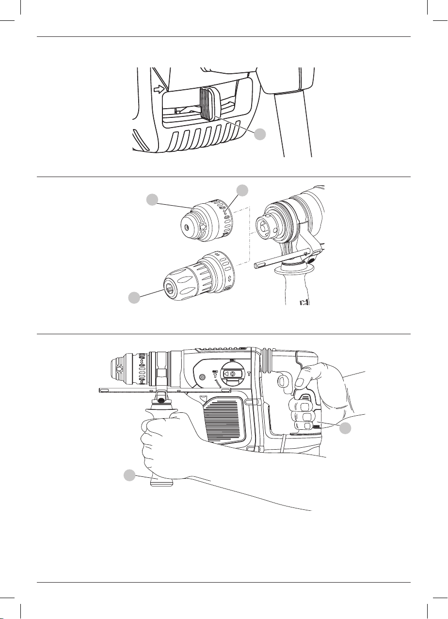
Fig. E
3
Fig. F
Fig. G
7
12
13
2
6
2
Page 5

HEAVY-DUTY ROTARY HAMMER
DeWALT
DeWALT
D25413, D25414, D25415, D25430
Congratulations!
You have chosen a
most reliable partners for professional power toolusers.
Technical Data
Voltage V
(U.K. & Ireland only) V
Type 1 1 1 1
Power Input W 1000 1000 1000 1000
Frequency Hz 50 50 50 50
No load speed min
No load beat per minutes bpm 0 – 4700 0 – 4700 0 – 4700 0 – 4700
Single impact energy (EPTA 05/2009)
Hammerdrilling J 4.2 4.2 4.2 –
Chiselling J 4.2 4.2 4.2 4.2
Maximum drilling range in steel/wood/concrete mm 13 / 32 / 32 13 / 32 / 32 13 / 32 / 32 –
Chisel positions 12 12 12 12
Core drilling capacity in soft brick mm 100 100 100 –
Tool holder SDS Plus SDS Plus SDS Plus SDS Plus
Collar diameter mm 60 60 60 60
Weight kg 4.2 4.3 4.3 4.0
tool. Years of experience, thorough product development and innovation make
D25413 D25414 D25415 D25430
AC
AC
-1
230 230 230 230
230/115 230/115 230/115 230/115
0 – 820 0 – 820 0 – 820 –
one of the
ENGLISH
Noise values and vibration values (triax vector sum) according to EN60745-2-6:
(emission sound pressure level) dB(A) 86 86 86 86
L
PA
(sound power level) dB(A) 3 3 3 3
L
WA
K (uncertainty for the given sound level) dB(A) 97 97 97 97
Drilling into metal
Vibration emission value a
= m/s
h
Uncertainty K = m/s
2
<2.5 <2.5 <2.5 –
2
1.5 1.5 1.5 –
Drilling into concrete
Vibration emission value a
= m/s
h, HD
Uncertainty K = m/s
2
2
8.2 8.2 8.2 –
1.5 1.5 1.5 –
Chiseling
Vibration emission value a
= m/s
h, Cheq
Uncertainty K = m/s
2
2
7.1 7.1 7.1 7.1
1.5 1.5 1.5 1.5
Screwdriving without impact
Vibration emission value a
= m/s
h
Uncertainty K = m/s
2
<2.5 <2.5 <2.5 –
2
1.5 1.5 1.5 –
3
Page 6

ENGLISH
DeWALT
DeWALT
DeWALT
DeWALT
DeWALT
The vibration emission level given in this information sheet has
been measured in accordance with a standardised test given in
EN60745 and may be used to compare one tool with another. It
may be used for a preliminary assessment ofexposure.
WARNING: The declared vibration emission level
represents the main applications of the tool. However if
the tool is used for different applications, with different
accessories or poorly maintained, the vibration emission
may differ. This may significantly increase the exposure
level over the total workingperiod.
An estimation of the level of exposure to vibration should
also take into account the times when the tool is switched
off or when it is running but not actually doing the job.
This may significantly reduce the exposure level over the
total workingperiod.
Identify additional safety measures to protect the operator
from the effects of vibration such as: maintain the tool
and the accessories, keep the hands warm, organisation
of workpatterns.
Fuses:
Europe 230V tools 10 Amperes. mains
U.K. & Ireland 230V tools 13 Amperes. in plugs
EC-Declaration of Conformity
Machinery Directive
Heavy-Duty Rotary Hammer
D25413, D25414, D25415
declares that these products described under
Technical Data are in compliance with:
2006/42/EC, EN60745-1:2009+A11:2010, EN60745-2-6:2010.
These products also comply with Directive 2014/30/EU and
2011/65/EU. For more information, please contact
the following address or refer to the back of themanual.
D25430
declares that these products described under
Technical Data are in compliance with:
2000/14/EC Electrical concrete breaker (hand held)
m</= 15kg, Annex VIII, TÜV Rheinland LGA Products GmbH
(0197), D-90431 Nürnberg, Germany, Notified Body ID No.: 0197
Level of acoustic power according to 2000/14/EC
(Article 12, Annex III, No. 10; m</= 15 kg)
L
(measured sound power level) dB 99
WA
L
(guaranteed sound power level) dB 105
WA
The undersigned is responsible for compilation of the technical
file and makes this declaration on behalf of
Markus Rompel
Director Engineering
, Richard-Klinger-Straße 11,
D-65510, Idstein, Germany
12.08.16
WARNING: To reduce the risk of injury, read the
instruction manual.
Definitions: Safety Guidelines
The definitions below describe the level of severity for each
signal word. Please read the manual and pay attention to
thesesymbols.
DANGER: Indicates an imminently hazardous
situation which, if not avoided, will result in death or
seriousinjury.
WARNING: Indicates a potentially hazardous situation
which, if not avoided, could result in death or
seriousinjury.
CAUTION: Indicates a potentially hazardous situation
which, if not avoided, may result in minor or
moderateinjury.
NOTICE: Indicates a practice not related to
personal injury which, if not avoided, may result in
propertydamage.
Denotes risk of electricshock.
Denotes risk offire.
General Power Tool Safety Warnings
at
.
WARNING: Read all safety warnings and all
instructions. Failure to follow the warnings and
instructions may result in electric shock, fire and/or
seriousinjury.
SAVE ALL WARNINGS AND INSTRUCTIONS
FOR FUTURE REFERENCE
The term “power tool” in the warnings refers to your mainsoperated (corded) power tool or battery-operated (cordless)
powertool.
1) Work area safety
a ) Keep work area clean and well lit. Cluttered or dark
areas inviteaccidents.
b ) Do not operate power tools in explosive
atmospheres, such as in the presence of flammable
liquids, gases or dust. Power tools create sparks which
may ignite the dust orfumes.
c ) Keep children and bystanders away while operating
a power tool. Distractions can cause you to losecontrol.
4
Page 7

2) Electrical safety
a ) Power tool plugs must match the outlet. Never
modify the plug in any way. Do not use any adapter
plugs with earthed (grounded) power tools.
Unmodified plugs and matching outlets will reduce risk of
electricshock.
b ) Avoid body contact with earthed or grounded
surfaces such as pipes, radiators, ranges and
refrigerators. There is an increased risk of electric shock if
your body is earthed orgrounded.
c ) Do not expose power tools to rain or wet conditions.
Water entering a power tool will increase the risk of
electricshock.
d ) Do not abuse the cord. Never use the cord for
carrying, pulling or unplugging the power tool. Keep
cord away from heat, oil, sharp edges or moving
parts. Damaged or entangled cords increase the risk of
electricshock.
e ) When operating a power tool outdoors, use an
extension cord suitable for outdoor use. Use of a cord
suitable for outdoor use reduces the risk of electricshock.
f ) If operating a power tool in a damp location is
unavoidable, use a residual current device (RCD)
protected supply. Use of an RCD reduces the risk of
electricshock.
3) Personal safety
a ) Stay alert, watch what you are doing and use
common sense when operating a power tool. Do not
use a power tool while you are tired or under the
influence of drugs, alcohol or medication. A moment
of inattention while operating power tools may result in
serious personalinjury.
b ) Use personal protective equipment. Always wear
eye protection. Protective equipment such as dust mask,
non-skid safety shoes, hard hat, or hearing protection used
for appropriate conditions will reduce personalinjuries.
c ) Prevent unintentional starting. Ensure the switch
is in the off position before connecting to power
source and/or battery pack, picking up or carrying
the tool. Carrying power tools with your finger on the
switch or energising power tools that have the switch on
invitesaccidents.
d ) Remove any adjusting key or wrench before turning
the power tool on. A wrench or a key left attached
to a rotating part of the power tool may result in
personalinjury.
e ) Do not overreach. Keep proper footing and balance
at all times. This enables better control of the power tool
in unexpectedsituations.
f ) Dress properly. Do not wear loose clothing or
jewellery. Keep your hair, clothing and gloves away
from moving parts. Loose clothes, jewellery or long hair
can be caught in movingparts.
g ) If devices are provided for the connection of dust
extraction and collection facilities, ensure these are
ENGLISH
connected and properly used. Use of dust collection
can reduce dust-relatedhazards.
4) Power tool use and care
a ) Do not force the power tool. Use the correct power
tool for your application. The correct power tool
will do the job better and safer at the rate for which it
wasdesigned.
b ) Do not use the power tool if the switch does not turn
it on and off. Any power tool that cannot be controlled
with the switch is dangerous and must berepaired.
c ) Disconnect the plug from the power source and/or
the battery pack from the power tool before making
any adjustments, changing accessories, or storing
power tools. Such preventive safety measures reduce the
risk of starting the power toolaccidentally.
d ) Store idle power tools out of the reach of children
and do not allow persons unfamiliar with the power
tool or these instructions to operate the power tool.
Power tools are dangerous in the hands of untrainedusers.
e ) Maintain power tools. Check for misalignment or
binding of moving parts, breakage of parts and any
other condition that may affect the power tool’s
operation. If damaged, have the power tool repaired
before use. Many accidents are caused by poorly
maintained powertools.
f ) Keep cutting tools sharp and clean. Properly
maintained cutting tools with sharp cutting edges are less
likely to bind and are easier tocontrol.
g ) Use the power tool, accessories and tool bits etc.,
in accordance with these instructions taking into
account the working conditions and the work to be
performed. Use of the power tool for operations different
from those intended could result in a hazardoussituation.
5) Service
a ) Have your power tool serviced by a qualified repair
person using only identical replacement parts. This
will ensure that the safety of the power tool ismaintained.
Additional Specific Safety Rules for Rotary
Hammers
• Wear ear protectors. Exposure to noise can cause
hearingloss.
• Use auxiliary handles supplied with the tool. Loss of
control can cause personal injury.
• Hold power tool by insulated gripping surfaces, when
performing an operation where the cutting accessory or
the fastener may contact hidden wiring or its own cord.
Cutting accessory contacting a “live” wire may make exposed
metal parts of the power tool “live” and could give the operator
an electric shock.
• Use clamps or other practical way to secure and support
the workpiece to a stable platform. Holding the work by
hand or against your body is unstable and may lead to loss
of control.
5
Page 8

ENGLISH
DeWALT
DeWALT
• Wear safety goggles or other eye protection. Hammering
operations cause chips to fly. Flying particles can cause
permanent eye damage. Wear a dust mask or respirator
for applications that generate dust. Ear protection may be
required for most applications.
• Keep a firm grip on the tool at all times. Do not attempt
to operate this tool without holding it with both hands.
It is recommended that the side handle be used at all times.
Operating this tool with one hand will result in loss of control.
Breaking through or encountering hard materials such as
re-bar may be hazardous as well. Tighten the side handle
securely before use.
• Do not operate this tool for long periods of time.
Vibration caused by hammer action may be harmful to your
hands and arms. Use gloves to provide extra cushion and limit
exposure by taking frequent rest periods.
• Do not recondition bits yourself. Chisel reconditioning
should be done by an authorized specialist. Improperly
reconditioned chisels could cause injury.
• Wear gloves when operating tool or changing bits.
Accessible metal parts on the tool and bits may get extremely
hot during operation. Small bits of broken material may
damage bare hands.
• Never lay the tool down until the bit has come to a
complete stop. Moving bits could cause injury.
• Do not strike jammed bits with a hammer to dislodge
them. Fragments of metal or material chips could dislodge
and cause injury.
• Slightly worn chisels can be resharpened by grinding.
• Keep the power cord away from the rotating bit. Do not
wrap the cord around any part of your body. An electric
cord wrapped around a spinning bit may cause personal
injury and loss of control.
WARNING: We recommend the use of a residual current
device with a residual current rating of 30mA or less.
Residual Risks
The following risks are inherent to the use of rotary hammers:
• injuries caused by touching the rotating parts or hot parts of
the tool.
In spite of the application of the relevant safety regulations
and the implementation of safety devices, certain residual risks
cannot be avoided. These are:
• Impairment of hearing.
• Risk of squeezing fingers when changing the accessory.
• Health hazards caused by breathing dust developed when
working in concrete and/or masonry.
Electrical Safety
The electric motor has been designed for one voltage only.
Always check that the power supply corresponds to the voltage
on the rating plate.
Your
with EN60745; therefore no earth wire is required.
6
tool is double insulated in accordance
WARNING: 115 V units have to be operated via a fail-safe
isolating transformer with an earth screen between the
primary and secondary winding.
If the supply cord is damaged, it must be replaced by a
specially prepared cord available through the
serviceorganisation.
Mains Plug Replacement
(U.K. & Ireland Only)
If a new mains plug needs to be fitted:
• Safely dispose of the oldplug.
• Connect the brown lead to the live terminal in theplug.
• Connect the blue lead to the neutralterminal.
WARNING: No connection is to be made to the
earthterminal.
Follow the fitting instructions supplied with good quality plugs.
Recommended fuse: 13A.
Using an Extension Cable
An extension cord should not be used unless absolutely
necessary. Use an approved extension cable suitable for
the power input of your charger (see Technical Data). The
minimum conductor size is 1.5 mm2; the maximum length
is30m.
When using a cable reel, always unwind the cablecompletely.
Package Contents
The package contains:
1 Heavy-duty rotary hammerdrill
1 Side handle
1 Depth adjustment rod (D25413, D25414, D25415 only)
1 Kitbox
1 Keyless chuck (D25414 and D25415 only)
1 Instruction manual
• Check for damage to the tool, parts or accessories which may
have occurred duringtransport.
• Take the time to thoroughly read and understand this manual
prior tooperation.
Markings on Tool
The following pictograms are shown on the tool:
Read instruction manual before use.
Wear ear protection.
Wear eye protection.
Date Code Position
The date code which also includes the year of manufacture, is
printed into thehousing.
Example:
2016 XX XX
Year of Manufacture
Page 9

Description (Fig.A–D,F)
WARNING: Never modify the power tool or any part of it.
Damage or personal injury couldresult.
1
Variable speed switch
2
Main handle
3
Forward / reverse slider
4
Mode selector
5
Safety lock
6
Side handle
7
Tool holder / locking sleeve
8
Shocks
9
LED Indicator (D25415 only)
10
Depth adjustment rod (D25413, D25414, D25415 only)
11
Depth stop clamp
12
Locking collar
13
Chuck (D25414 and D25415 only)
14
Dust cover
15
Lock on button (D25430 only)
Intended Use
D25413, D25414, D25415
These heavy-duty rotary hammers have been designed for
professional drilling and hammerdrilling, screwdriving and
lightchipping.
D25430
This chipping hammer has been designed for professional
chipping, chiselling and demolition applications.
DO NOT use under wet conditions or in the presence of
flammable liquids orgases.
These hammerdrills are professional power tools.
DO NOT let children come into contact with the tool.
Supervision is required when inexperienced operators use
thistool.
• Young children and the infirm. This appliance is not
intended for use by young children or infirm persons
without supervision.
• This product is not intended for use by persons (including
children) suffering from diminished physical, sensory or
mental abilities; lack of experience, knowledge or skills
unless they are supervised by a person responsible for their
safety. Children should never be left alone with thisproduct.
Active Vibration Control (Fig. A)
The active vibration control neutralises rebound vibration from
the hammer mechanism. Lowering hand and arm vibration
allows for more comfortable use for longer periods of time and
extends the life of the unit.
For best vibration control, hold the tool with one hand on the
main handle
Apply just enough pressure so the hammer is approximately
mid-stroke.
The hammer only needs enough pressure to engage the active
vibraton control. Applying too much pressure will not make
2
and the other hand on the side handle
6
.
ENGLISH
the tool drill or chip faster and active vibration control will
notengage.
Torque Limiting Clutch
WARNING: The user must always maintain a firm grip on
the tool when in operation.
The torque limiting clutch reduces the maximum torque
reaction transmitted to the operator in case of jamming of a drill
bit. This feature also prevents the gearing and electric motor
from stalling.
NOTICE: Always turn the tool off before changing torque
control settings or damage to tool may result.
Anti Rotation System D25415 (Fig. B)
The anti rotation system offers increased user comfort and
safety through an on-board, anti-rotation technology capable
of detecting if the user loses control of the hammer. When a
jam is detected, the torque and speed are reduced instantly.
This feature prevents self rotation of the tool reducing the
occurrence of wrist injuries. The red LED indicator
the anti-rotational device is activated.
9
lights up if
ASSEMBLY AND ADJUSTMENTS
WARNING: To reduce the risk of serious personal
injury, turn tool off and disconnect tool from power
source before making any adjustments or removing/
installing attachments or accessories. Be sure the
trigger switch is in the OFF position. An accidental start-up
can cause injury.
Selecting the Operating Mode (Fig. C)
D25413, D25414, D25415
The tool can be used in the following operating modes:
Rotary drilling: for screwdriving and for drilling into
steel, wood and plastics.
Hammerdrilling: for concrete and masonry drilling
operations.
Hammering only: for light chipping, chiselling and
demolition applications. In this mode the tool can
also be used as a lever to free a jammed drill bit
D25430
The tool can be used in the following operating modes:
Hammering only: for light chipping, chiselling and
demolition applications. In this mode the tool can
also be used as a lever to free a jammed drill bit.
1. To select the operating mode, press the safety lock
rotate the mode selector switch
symbol of the required mode.
2. Release the safety lock and check that the mode selector
switch is locked in place.
WARNING: Do not select the operating mode when the
tool is running.
4
until it points to the
5
and
7
Page 10

ENGLISH
Indexing the Chisel Position (Fig.C)
The chisel can be indexed and locked into 12 different positions.
1. Rotate the mode selector switch
the hammerdrill mode symbol. Refer to Selecting the
Operating Mode in Assembly and Adjustments.
2. Rotate the chisel in the desired position.
3. Set the mode selector switch
onlyposition.
4. Twist the chisel until it locks in position.
4
until it points to
4
to the hammering
Inserting and Removing SDS Plus Accessories
(Fig. D)
This tool uses SDS Plus accessories (refer to the inset in FigureD
for a cross-section of an SDS Plus bit shank). We recommend
using professional accessories only.
1. Clean and grease the bit shank.
2. Insert the bit shank into the tool holder/locking sleeve
3. Push the bit down and turn it slightly until it fits into
theslots.
4. Pull on the bit to check if it is properly locked. The
hammering function requires the bit to be able to move
axially several centimetres when locked in the tool holder.
5. To remove a bit, pull back the tool holder/locking sleeve
and pull out the bit.
WARNING: Always wear gloves when you change
accessories. The exposed metal parts on the tool and
accessory may become extremly hot during operation.
7
.
7
Fitting the Side Handle (Fig. A)
The side handle
1. Loosen the side handle.
2. For RH-users: slide the side handle clamp over the collar
behind the tool holder, handle at the left.
For LH-users: slide the side handle clamp over the collar
behind the tool holder, handle at the right.
3. Rotate the side handle to the desired position and tighten
the handle.
6
can be fitted to suit both RH- and LH-users.
WARNING: Do not use the tool without the side handle
properly assembled.
Setting the Drilling Depth (Fig. D)
D25413, D25414, D25415 only
1. Insert the required drill bit as described above.
2. Press the depth stop clamp
3. Fit the depth adjustment rod
depth stop clamp.
4. Adjust the drilling depth as shown.
5. Release the depth stop clamp.
11
and keep it depressed.
10
through the hole in the
Forward/reverse Slider (Fig. E)
1. Push the forward/reverse slider
(RH) rotation. See arrows on tool.
3
to the LH-side for forward
2. Push the forward/reverse slider
(LH) rotation.
WARNING: Always wait until the motor has come to
a complete standstill before changing the direction
ofrotation.
3
to the RH-side for reverse
Fitting a Chuck Adapter and Chuck
(Sold Separately)
1. Screw a chuck onto the threaded end of the chuck adapter.
2. Insert the connected chuck and adapter in the tool as
though it were a standard SDS Plus bit.
3. To remove the chuck, proceed as for removing a standard
SDS Plus bit.
WARNING: Never use standard chucks in the
hammerdrilling mode.
Consult your dealer for further information on the
appropriateaccessories.
Replacing the Tool Holder with the Chuck
(Fig. F)
D25414 and D25415 only
1. Turn the locking collar
pull the tool holder/locking sleeve
2. Push the chuck
collar into the locking position.
3. To replace the chuck with the tool holder, first remove the
chuck the same way as the tool holder was removed. Then
place the tool holder the same way as the chuck was placed.
WARNING: Never use standard chucks in the
hammerdrilling mode.
12
into the unlocking position and
7
off.
13
onto the spindle and turn the locking
Replacing the Dust Cover (Fig. A, D)
The dust cover
Replace a worn dust cover immediately.
1. Pull back the tool holder locking sleeve
cover
2. Fit the new dust cover.
3. Release the tool holder locking sleeve.
14
prevents dust ingress into the mechanism.
14
off.
7
and pull the dust
OPERATION
Instructions for Use
WARNING: Always observe the safety instructions and
applicableregulations.
WARNING: To reduce the risk of serious personal
injury, turn tool off and disconnect tool from power
source before making any adjustments or removing/
installing attachments or accessories. Be sure the
trigger switch is in the OFF position. An accidental start-up
can cause injury.
WARNING:
• Be aware of the location of pipework and wiring.
8
Page 11

• Apply only a gentle pressure to the tool (approx.
5kg). Excessive force does not speed up drilling but
decreases tool performance and may shorten tool life.
• Do not drill or drive too deep to prevent damage to the
dust cover.
• Always hold the tool firmly with both hands and
ensure a secure stance (Fig. G). Always operate the
tool with the side handle properly mounted.
Proper Hand Position (Fig.G)
WARNING: To reduce the risk of serious personal injury,
ALWAYS use proper hand position as shown.
WARNING: To reduce the risk of serious personal
injury, ALWAYS hold securely in anticipation of a
suddenreaction.
Proper hand position requires one hand on the side handle
with the other hand on the main handle
2
.
6
Overload Clutch
If the drill bit becomes jammed or caught, the drive to the drill
spindle is interrupted by the overload clutch. Because of the
forces that occur as a result, always hold the machine securely
with both hands and take a firm stance.
Switching On and Off (Fig. A)
1. To run the tool, press the variable speed switch
pressure exerted on the variable speed switch determines
the tool speed.
2. To stop the tool, release the switch.
3. To lock the tool in the off position, move the forward/
reverse slider
3
to the central position.
1
. The
Hammerdrilling (Fig. A)
Drilling with a Solid Bit
1. Set the mode selector switch
position. Refer to Selecting the Operating Mode in
Assembly and Adjustments.
2. Insert the appropriate drill bit.
NOTE: For best results use high quality carbide-tipped bits.
3. Adjust the side handle
4. If necessary, set the drilling depth.
5. Mark the spot where the hole is to be drilled.
6. Place the drill bit on the spot and switch on the tool.
7. Always switch off the tool when work is finished and
beforeunplugging.
4
to the hammerdrilling
6
as required.
Drilling with a Core Bit (Fig. A, C)
1. Set the mode selector
Refer to Selecting the Operating Mode in Assembly
andAdjustments.
2. Adjust the side handle
3. Insert the appropriate core bit.
4. Assemble the centredrill into the core bit.
4
to the hammerdrilling position.
6
as required.
5. Place the centredrill on the spot and press the variable
speed switch
concrete approx. 1 cm.
6. Stop drilling and remove the centredrill. Place the core bit
back into the hole and continue drilling.
7. When drilling through a structure thicker than the depth of
the core bit, break away the round cylinder of concrete or
core inside the bit at regular intervals. To avoid unwanted
breaking away of concrete around the hole, first drill a hole
the diameter of the center drill completely through the
structure. Then drill the cored hole halfway from each side.
8. Always switch off the tool when work is finished and
beforeunplugging.
1
. Drill until the core penetrates into the
Rotary Drilling (Fig. C)
,
D25413, D25414, D25415 only
1. Set the mode selector switch
position. Refer to Selecting the Operating Mode in
Assembly and Adjustments.
2. Fit the chuck adapter/chuck assembly.
3. Proceed as described for hammerdrilling.
WARNING: Never use standard chucks in the
hammerdrilling mode.
4
to the rotary drilling
Screwdriving (Fig. A, C)
D25413, D25414, D25415 only
1. Set the mode selector switch
position. Refer to Selecting the Operating Mode in
Assembly and Adjustments.
2. Select the direction of rotation.
3. Insert the special SDS Plus screwdriving adaptor for use with
hexagonal screwdriver bits.
4. Insert the appropriate screwdriver bit. When driving slotted
head screws always use bits with a finder sleeve.
5. Gently press the variable speed switch
damage to the screw head. In reverse (LH) rotation the tool
speed is automatically reduced for easy screw removal.
6. When the screw is flush with the workpiece, release the
variable speed switch to prevent the screw head from
penetrating into the workpiece.
4
to the rotary drilling
1
to prevent
Chipping and Chiselling (Fig. A, C)
1. Set the mode selector switch
position. Refer to Selecting the Operating Mode in
Assembly and Adjustments.
2. Insert the appropriate chisel and rotate it by hand to lock it
into one of 12 positions.
3. Adjust the side handle
4. Switch on the tool and start working.
5. Always switch off the tool when work is finished and
beforeunplugging.
WARNING:
• Do not use this tool to mix or pump easily combustible
or explosive fluids (benzine, alcohol, etc.).
4
to the hammering only
6
as required.
ENGLISH
9
Page 12

ENGLISH
DeWALT
DeWALT
DeWALT
DeWALT
DeWALT
• Do not mix or stir flammable liquids labelled
accordingly.
MAINTENANCE
Your
over a long period of time with a minimum of maintenance.
Continuous satisfactory operation depends upon proper tool
care and regularcleaning.
power tool has been designed to operate
WARNING: To reduce the risk of serious personal
injury, turn tool off and disconnect tool from power
source before making any adjustments or removing/
installing attachments or accessories. Be sure the
trigger switch is in the OFF position. An accidental start-up
can cause injury.
Motor Brushes
uses an advanced brush system which automatically
stops the drill when the brushes wear out. This prevents serious
damage to the motor. New brush assemblies are available
at authorised
replacement parts.
service centers. Always use identical
Lubrication
Your power tool requires no additionallubrication.
Cleaning
WARNING: Blow dirt and dust out of the main housing
with dry air as often as dirt is seen collecting in and around
the air vents. Wear approved eye protection and approved
dust mask when performing thisprocedure.
WARNING: Never use solvents or other harsh chemicals
for cleaning the non-metallic parts of the tool. These
chemicals may weaken the materials used in these parts.
Use a cloth dampened only with water and mild soap.
Never let any liquid get inside the tool; never immerse any
part of the tool into aliquid.
Protecting the Environment
Separate collection. Products and batteries marked
with this symbol must not be disposed of with normal
household waste.
Products and batteries contain materials that can
be recovered or recycled reducing the demand for raw
materials. Please recycle electrical products and batteries
according to local provisions. Further information is available at
www.2helpU.com.
Optional Accessories
WARNING: Since accessories, other than those offered
by
of such accessories with this tool could be hazardous.
To reduce the risk of injury, only
accessories should be used with thisproduct.
Consult your dealer for further information on the
appropriateaccessories.
10
, have not been tested with this product, use
recommended
Page 13

111213
Page 14

Page 15

Page 16

Belgique et
Luxembourg België
en Luxemburg
D
eWALT - Belgium BVBA
Egide Walschaertsstraat 16
2800 Mechelen
Tel: NL 32 15 47 37 63
Tel: FR 32 15 47 37 64
Fax: 32 15 47 37 99
www.dewalt.be
enduser.BE@SBDinc.com
Danmark D
eWALT
Roskildevej 22
2620 Albertslund
Tel: 70 20 15 10
Fax: 70 22 49 10
www.dewalt.dk
kundeservice.dk@sbdinc.com
Deutschland D
eWALT
Richard Klinger Str. 11
65510 Idstein
Tel: 06126-21-1
Fax: 06126-21-2770
www.dewalt.de
infodwge@sbdinc.com
Ελλάς D
eWALT (Ελλάς) Α.Ε.
EΔΡΑ-ΓΡΑΦΕΙΑ : Στράβωνος 7
& Λ. Βουλιαγμένης, Γλυφάδα 166 74, Αθήνα
SERVICE : Ημερος Τόπος 2 (Χάνι Αδάμ) – 193 00 Ασπρόπυργος
Τηλ: 00302108981616
Φαξ: 00302108983570
www.dewalt.gr
Greece.Service@sbdinc.com
España D
eWALT Ibérica, S.C.A.
Parc de Negocios “Mas Blau”
Edificio Muntadas, c/Bergadá, 1, Of. A6
08820 El Prat de Llobregat (Barcelona)
Tel: 934 797 400
Fax: 934 797 419
www.dewalt.es
respuesta.postventa@sbdinc.com
France D
eWALT
5, allée des Hêtres
BP 30084, 69579 Limonest Cedex
Tel: 04 72 20 39 20
Fax: 04 72 20 39 00
www.dewalt.fr
scufr@sbdinc.com
Schweiz
Suisse
Svizzera
D
eWALT
In der Luberzen 42
8902 Urdorf
Tel: 044 - 755 60 70
Fax: 044 - 730 70 67
www.dewalt.ch
service@rofoag.ch
Ireland D
eWALT
Calpe House Rock Hill
Black Rock, Co. Dublin
Tel: 00353-2781800
Fax: 00353-2781811
www.dewalt.ie
Italia D
eWALT
via Energypark
20871 Vimercate (MB), IT
Tel: 800-014353
39 039 9590200
Fax: 39 039 9590313
www.dewalt.it
Nederlands D
eWALT Netherlands BV
Holtum Noordweg 35
6121 RE BORN, Postbus 83, 6120 AB BORN
Tel: 31 164 283 063
Fax: 31 164 283 200
www.dewalt.nl
Norge D
eWALT
Postboks 4613, Nydalen
0405 Oslo
Tel: 45 25 13 00
Fax: 45 25 08 00
www.dewalt.no
kundeservice.no@sbdinc.com
Österreich D
eWALT
Werkzeug Vertriebsges m.b.H
Oberlaaerstrasse 248, A-1230 Wien
Tel: 01 - 66116 - 0
Fax: 01 - 66116 - 614
www.dewalt.at
service.austria@sbdinc.com
Portugal D
eWALT Limited, SARL
Centro de Escritórios de Sintra Avenida
Almirante Gago Coutinho, 132/134, Edifício 14
2710-418 Sintra
Tel: 214 66 75 00
Fax: 214 66 75 80
www.dewalt.pt
resposta.posvenda@sbdinc.com
Suomi D
eWALT
PL 47
00521 Helsinki
Puh: 010 400 4333
Faksi: 0800 411 340
www.dewalt.fi
asiakaspalvelu.fi@sbdinc.com
Sverige D
eWALT
Box 94
431 22 Mölndal
Tel: 031 68 61 60
Fax: 031 68 60 08
www.dewalt.se
kundservice.se@sbdinc.com
Türkiye KALE Hırdavat ve Makina A.Ş.
Defterdar Mah. Savaklar Cad. No:15
Edirnekapı / Eyüp / İSTANBUL 34050 TÜRKİYE
Tel: 0212 533 52 55
Faks: 0212 533 10 05
www.dewalt.com.tr
United
Kingdom
D
eWALT, 210 Bath Road;
Slough, Berks SL1 3YD
Tel: 01753-567055
Fax: 01753-572112
www.dewalt.co.uk
emeaservice@sbdinc.com
Australia D
eWALT
810 Whitehorse Road Box Hill
VIC 3103 Australia
Tel: Aust 1800 338 002
Tel: NZ 0800 339 258
www.dewalt.com.au
www.dewalt.co.nz
Middle East Africa D
eWALT
P.O. Box - 17164,
Jebel Ali Free Zone (South), Dubai, UAE
Tel: 971 4 812 7400
Fax: 971 4 2822765
www.dewalt.ae
Service.MEA@sbdinc.com
N492413
14
08/16
 Loading...