

Page 1
INS-2049F April 20, 2007
BLK COM
RED OPEN
WHT CLOSED
WHT
RED
BLK
Detex Corporation, 302 Detex Drive, New Braunfels, Texas 78130 (830)629-2900 1-800-729-3839 FAX (830)620-6711
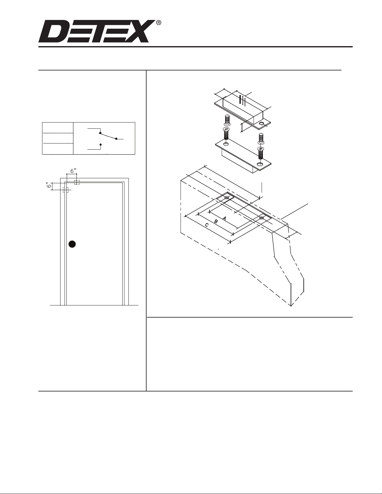
INSTALLATION INSTRUCTIONS FOR MAGNETIC SWITCH MS-2049F
ELECTRICAL
SPECIFICATIONS
SWITCH (SPDT)
MAXIMUM CONTACT RATING;
500 mA at 24V
SHOWN DOOR SECURE
E-Mail: [email protected] Internet: www.detex.com
1 - 1/16”
1 - 1/2”
6” TO CENTER OF MAGNET
3 - 1/2” CENTERED ON PLATE
SWITCH MS-2058
SWITCH - PLATE
1.25X4.875X.075
HOLE CENTERS SAME
AS MAGNET PLATE
SCREWS FOR SWITCH
AND MAGNET ARE
#8-32
P/N MS-2053
MAGNET MS-2057
MAGNET PLATE
1.25X4.875X.075
DOOR
MS-2049F POSITION
The preferred position of the magnetic switch is the top of the door,
centered approximately 6” from the
edge of the door, as shown.
Contacts should be installed so that
the door cannot be opened more than
2 inches without causing an alarm
condition.
1-1/4” MIN
NOTE: DOOR AND FRAME PREPARATION
PER ANSI A115.2
DIMENSIONS:
A = 3-1/2” MIN B = 4-1/8” C = 4-15/16” MIN
NOTE: The dimensions given in the illustration apply to the door and
frame preparation for top of door or latch side installation.
Special screws, #8-32 x 1/4” at head are provided.
Special attention must be given to the alignment of the switch and
magnet, especially longitudinal. The maximum allowable misalignment in any direction is 1/8”.
DETEX INS2049F
 Loading...