

Page 1
103104 January 20, 2009
Detex Corporation, 302 Detex Drive, New Braunfels, Texas 78130-3045
(830)629-2900 / 1-800-729-3839 / Fax (830)620-6711
E-MAIL: [email protected] INTERNET: www.detex.com
INSTALLATION INSTRUCTIONS FOR ARCHITECTURAL VALUE SERIES®
ELECTRIC DOGGING / ELECTRIC LATCH RETRACTION AND "H" MODELS (HURRICANE)
U.S. PATENT NUMBERS:
V40
ED Electric Dogging
ER ELECTRIC LATCH RETRACTION
RIM
INTERNATIONAL PATENT NUMBER:
6205825B1
6532777B2
PCT6009732
6009732
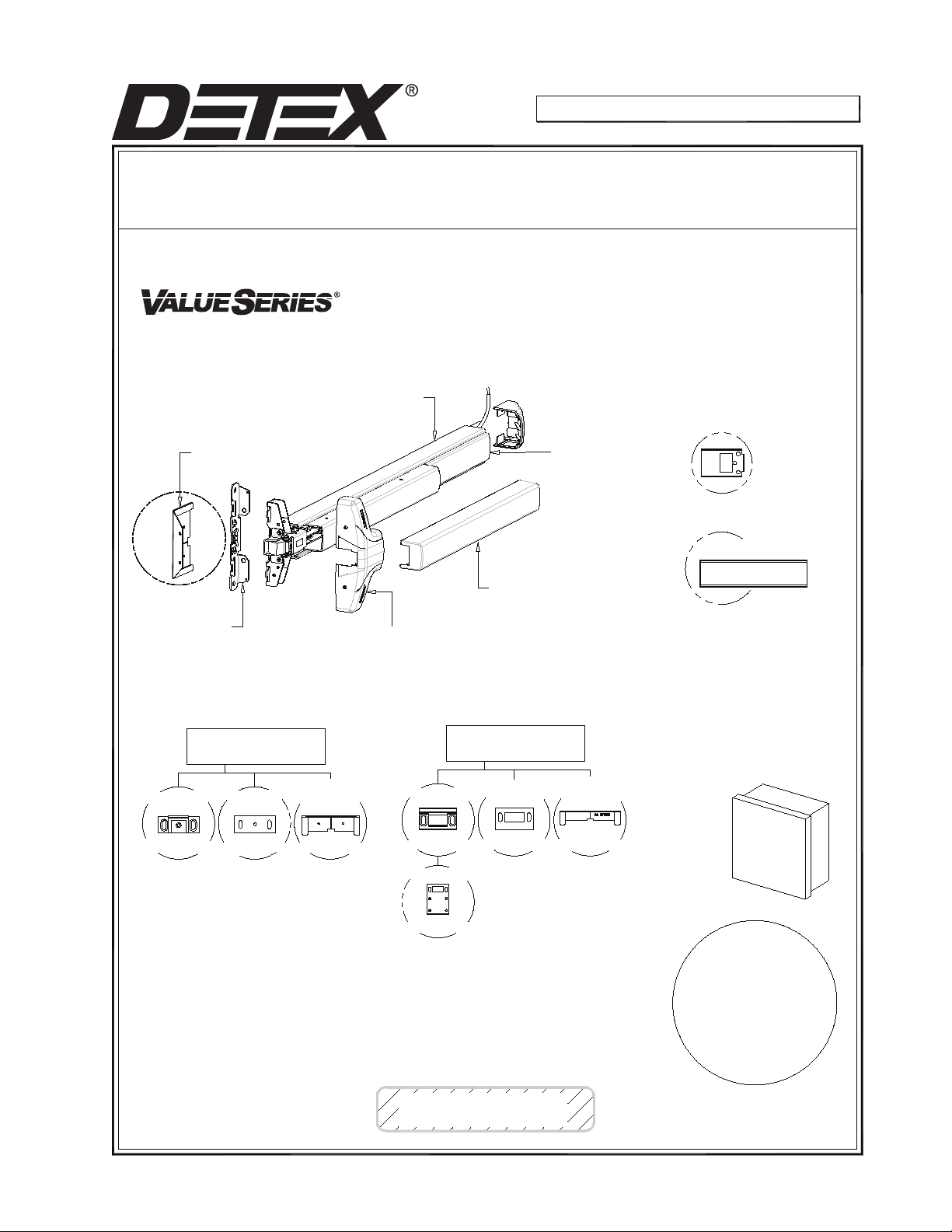
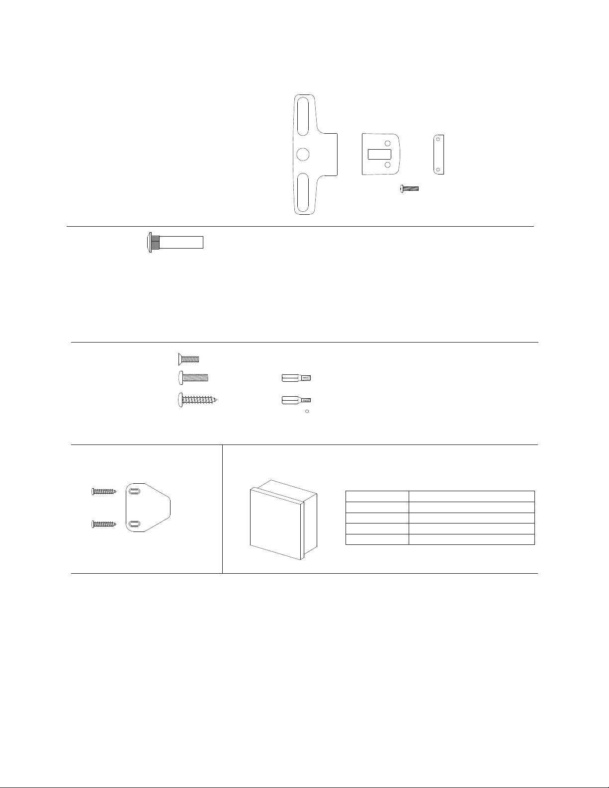
Parts Check List
Centercase/Pushpad/Module SubAssembly
P/N: ED 102457-X
ER 102458-X
Plastic Template
Use for ease of installation
Mounting plate
Subassembly
P/N: 100696-1
V40
99 Strike *, P/N: 100855-2
Non-Roller Strike Strike Shim
Standard
Plastic Template
Centercase Cover
P/N: 101805-1
Mortise Strike
Endcap
P/N: 101822
Fillerplate SubAssembly
Pushpad Wrap
P/N: 101810-2 (3-0)
P/N: 101815-2 (4-0)
V40NS
98 Strike *, P/N: 100855-1
Mortise
Strike Shim
2" Narrow Stile
Plastic Template
Endcap Bracket
P/N: 101821
Fillerplate (ER/ED)
P/N: 100408-11 (3-0)
P/N: 100518-11 (3-0 EXT)
P/N: 100417-11 (4-0)
P/N: 100554-11 (4-0 EXT)
Power Supply
See Accessories
on Page 13
DETEX
P/N: 100234-1 P/N: 100088
P/N: 100212
* Note:
Parts listed above will vary
according to product
configuration.
*Narrow Stile "NS" option
Mortise cylinder not included with device.
Standard Yale type cam required.
Owner's Copy
P/N: 100480 P/N: 100482
Strike Shield
P/N: 100481
103104 PAGE 1
P/N: 101899
See
Optional Accessories
- Glass Bead Kit
- Sex Nuts
- Tamper Kit
- Double Door Strike Kit
- Key Stop Kit
- Narrow Stile Kit
For:
Page 2
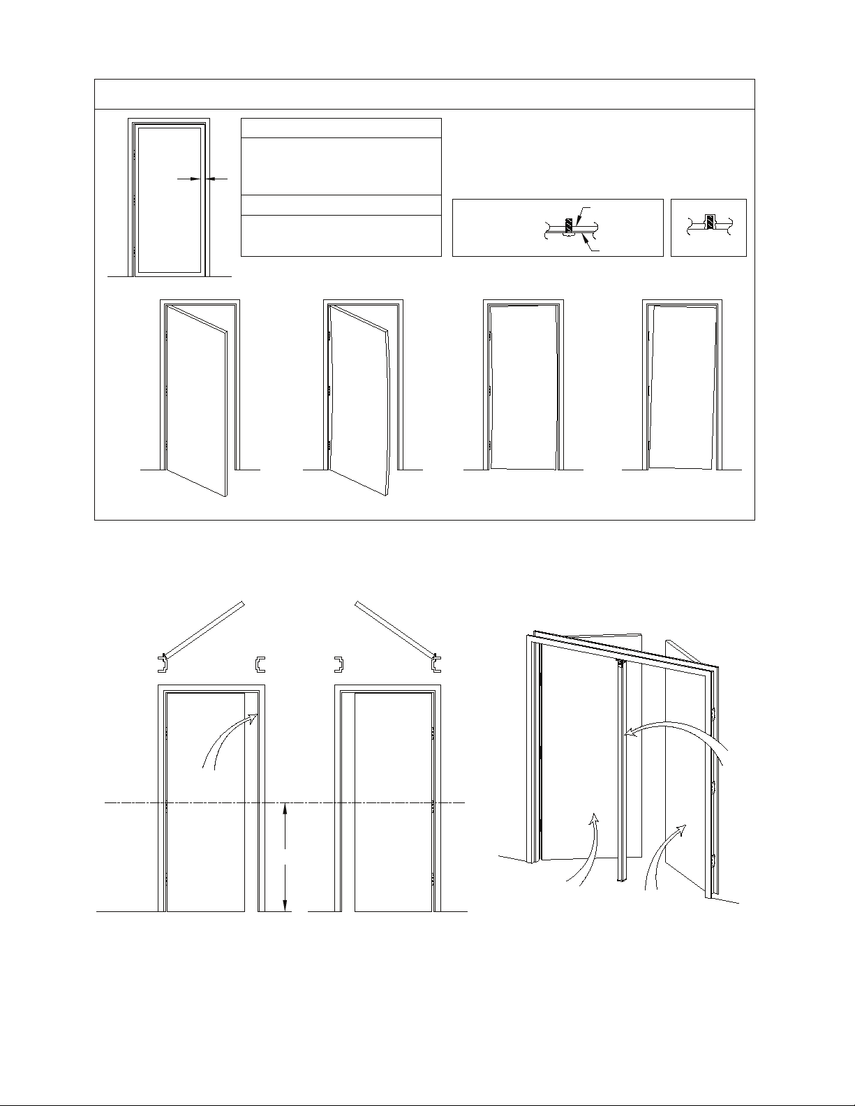
!!!CHECK BEFORE STARTING!!!
Door Must Swing Freely
Wide Stile (Surface Strike)
Minimum door stile 4-1/2" (114 mm)
Template drawings provide door and frame
structural and dimensional specifications for
door and frame preparation.
Narrow Stile
Minimum door stile 2" (51mm)
Surface strike possible
Mortise strike recommended
X
Door Must Not be Warped
Doors and frames with walls having a structural thickness (metal skin
plus reinforcement, or solid wood) to engage less than (3) full
screw threads, are considered unreinforced for hardware.
Unreinforced Doors: Use Sex Nuts and Bolts
Unreinforced Frames: Use Blind Rivet Nuts (see sketch)
Fasteners for unreinforced openings are not supplied by Detex.
Reinforced door or
frame engages at
least (3) screw
threads.
Reinforcement
Door Skin
Blind Rivet Nut
X
X
X
Door Must Not Bind
Door Must Not Sag
NOTE: 750mm MAXIMUM DOOR WIDTH OPENING FOR EUROPE FOR 36" DEVICE
(1000mm MAXIMUM DOOR WIDTH OPENING FOR EUROPE FOR 48" DEVICE)
THE SAFETY FEATURES OF THIS PRODUCT ARE ESSENTIAL TO ITS COMPLIANCE WITH EN 1125.
NO MODIFICATION OF ANY KIND, OTHER THAN THOSE DESCRIBED IN THESE INSTRUCTIONS ARE PERMITTED.
LHR Door
RHR Door
Inside Face
LHR Door
Inside Face
Horizontal
Reference
Finished
Floor
RHR Door
Stop Face
40"
C
L
Mullion
Face
103104 Page 2
Page 3
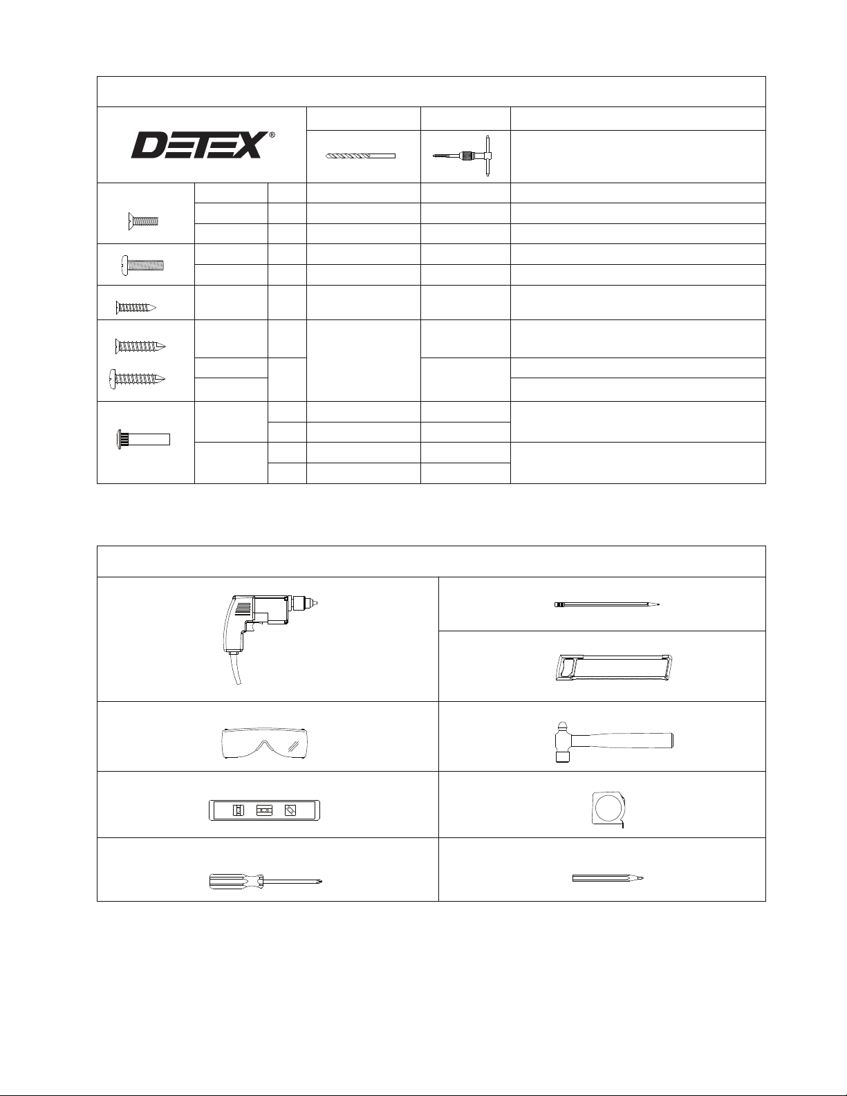
Fastener Table
Tap Wrench
#6-32 Tap
#10-24 Tap
#1/4-20 Tap
Machine Screws
Sheetmetal Screws
Self-drilling Screws
Sex Nut
#6-32 x 5/8"
#6-32 x 3/8"
#10-24 x 5/8"
#1/4-20 x 1/4"
#1/4-20 x 1"
#6 x 1"
#10 x 1"
#14 x 1"
#14 x 1-1/2"
#1/4-20
#10-32
PPH
PPH
PPH
PPH
PPH
PFH
PFH
PPH
----
----
----
----
#36 or 7/64
#25 or 9/64"
#7 or 13/64"
No pilot hole necessary for
self-drilling screws
9/32" Interior Door Face
3/8" Exterior Door Face
13/64" Interior Door Face
5/16" Exterior Door Face
Drill Bit
-----
-----
9/64"
Note: (1) Fastener selection will vary per catalog configuration and kits ordered.
(2) Mortise cylinder NOT provided.
(3) For wood applications use Wood Door Kit, p/n 103991(supplied separately).
-----
-----
-----
-----
-----
-----
-----
-----
-----
Comments
Use Either Machine Screws, Sheetmetal Screws,
Used on 98 Strike Shield Mounting Holes
Used to Mount Centercase Cover and Endcap
Used on 99 Strike Center Mounting Hole
Used to Fasten Centercase Unit onto Mounting plate
Used on Strike, Mounting plate, and Endcap Mounting Holes
Used on 98 Strike Shield Mounting Holes
Used on 99 Strike Center Mounting Hole
Used on Mounting plate and Endcap Mounting Holes
Recommended on Fire Rated Wood and
Used on Mounting plate and Endcap Mounting Holes
Recommended on Fire Rated Wood and
Used on Strike Hook Mounting Holes
or Sex Nuts
Used on Strike
Metal Applications
Unreinforced Hollow Metal Doors
Unreinforced Hollow Metal Doors
Power Drill
Safety Glasses
Level
Screw Driver
Tools Required
Pencil
Hack Saw
Hammer
Tape Measure
Center Punch
103104 Page 3
Page 4
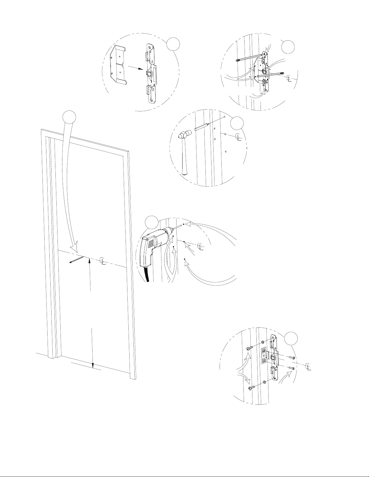
Mounting plate
2
Strike holes
hole
3
If necessary, remove
label temporarily
to mark trim hole
Slide 99 strike locator
into mounting plate.
1
(if using a 98 strike, see
98 STRIKE INSTALLATION page)
Mounting plate Hole
4
Punch marked
holes
Mark mounting plate
and strike holes
5
Mounting plate holes (2)
Trim input hole
if necessary.
(see outside
trim instructions)
For 1/4-20 machine screws drill #7 holes.
For #14 self-drilling screws no pilot holes
necessary.
For sex nuts drill 3/8" holes.
(see fastener table)
RECOMMENDED
Mark centerline
for unit
40 inches above
finished floor
Strike holes (2)
For 1/4-20 machine screws
drill #7 holes
No pilot hole necessary
for #14 self-drilling screws
(see fastener table)
Fasten tightly with
lockwashers and
1/4-20x1" machine
screws or #14
self-drilling screws
103104 Page 4
6
Fasten loosely with
two 1/4-20x1" machine
screws or #14
self-drilling screws
Page 5
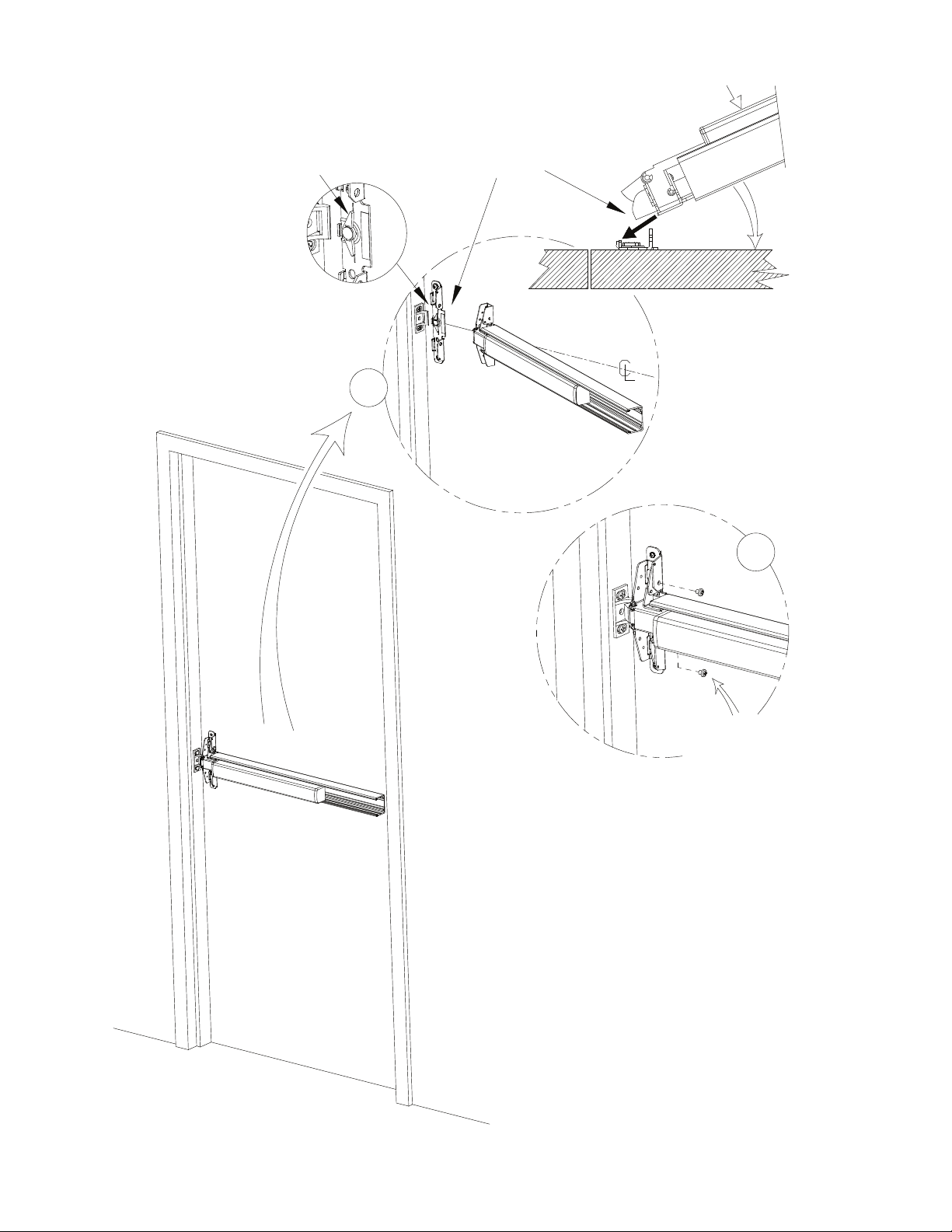
Position cam as shown
1
Insert centercase into slots
of centercase mounting plate,
depress pushpad, rotate
toward door.
DOOR
2
103104 Page 5
Fasten rim device
to mounting plate
with 1/4-20 x 1/4" PPH
MUST BE INSTALLED!
Page 6
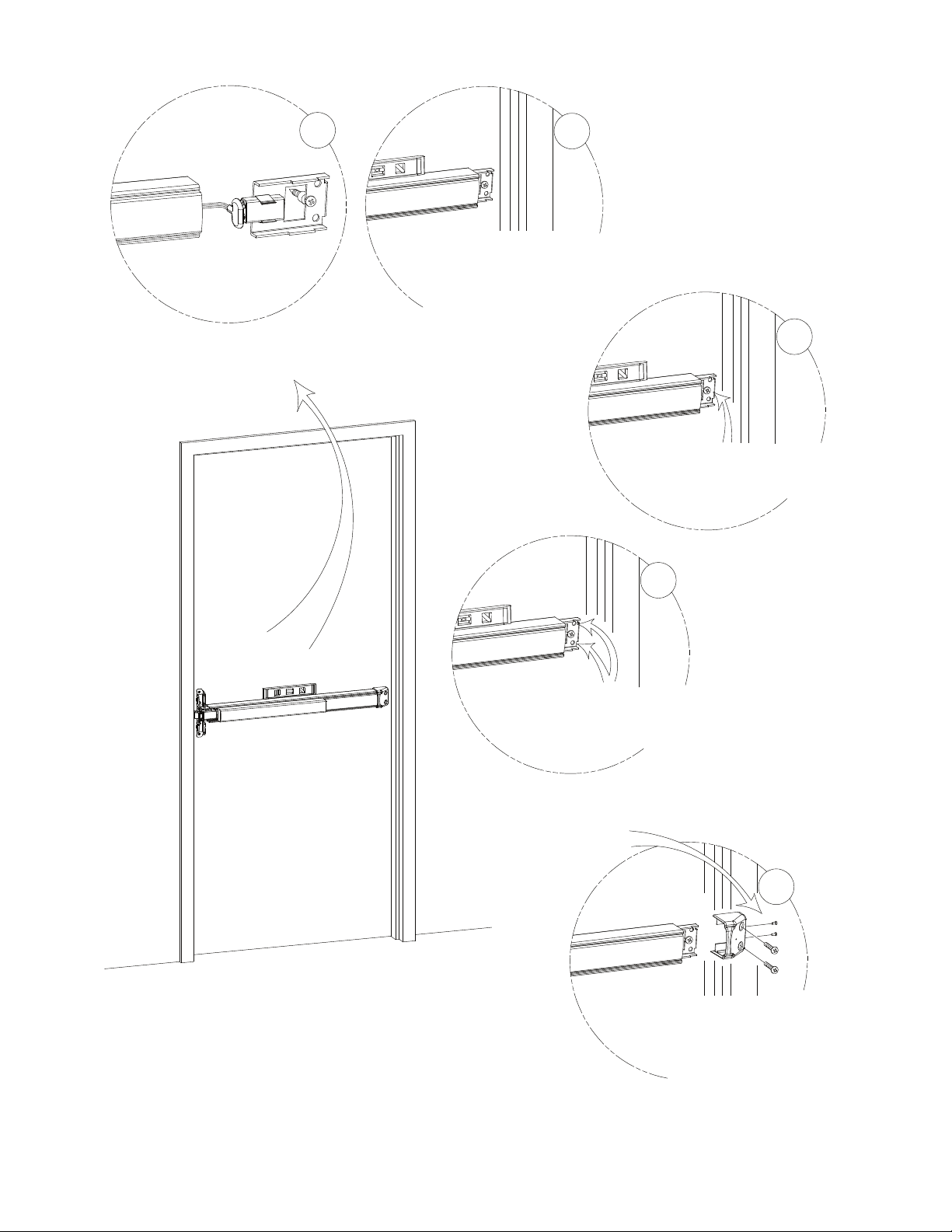
1
Slide fillerplate & endcap bracket into
extrusion & level pushpad assembly.
Note: Endcap Bracket must bottom-out
on extrusion. DO NOT REMOVE
NYLON SPACER ON BACK OF
BRACKET!
2
3
With pushpad assembly level,
secure the endcap bracket to door
by tightening the factory installed
self-drilling screw.
4
For 1/4-20 machine screws drill #7 holes.
For #14 self-drilling screws no pilot holes
necessary.
For sex nuts drill 3/8" holes.
see HARDWIRE TRANSFER OPTIONS page
IMPORTANT:
Install (2) 6-32 FH Screws
for added security
5
Slide and mount endcap
to endcap bracket with two
1/4-20x1" PPH machine screws
or #14 self-drilling screws.
DO NOT OVERTIGHTEN
103104 Page 6
Page 7
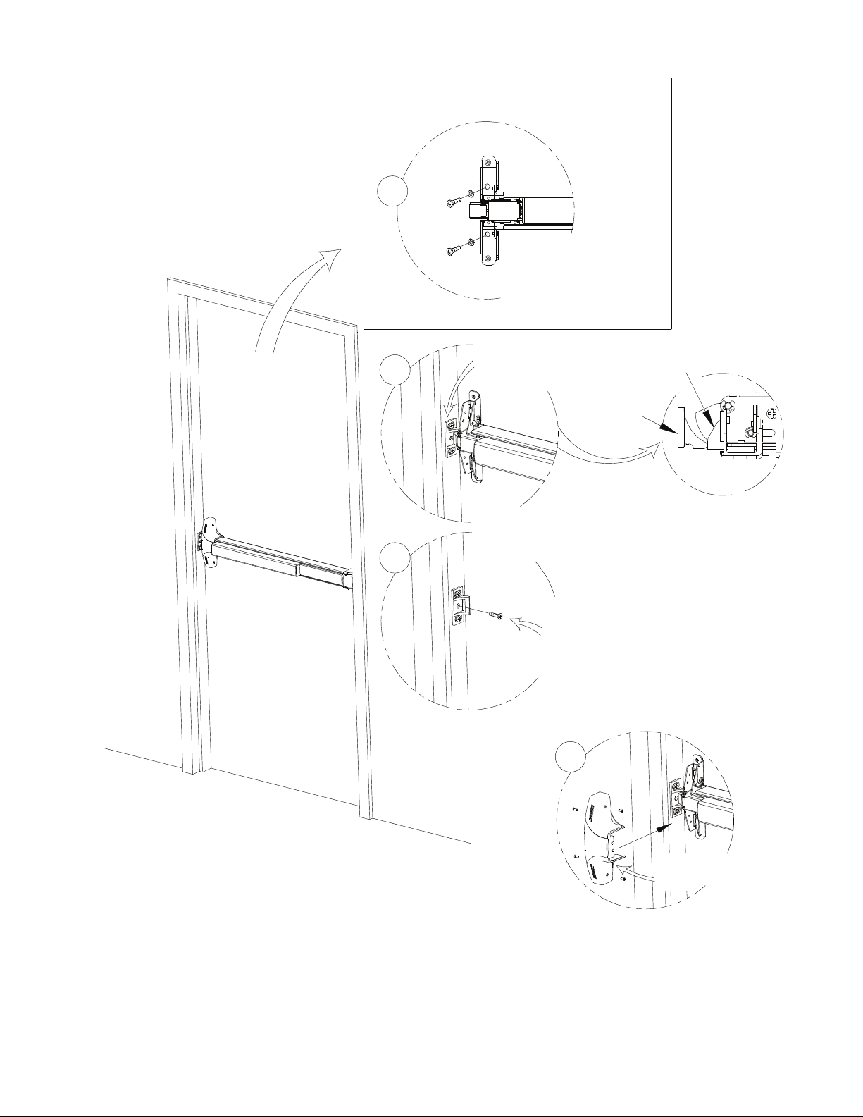
For Hurricane Models
(see Hurricane kit)
1
2
3
Fasten rim device to mounting
plate and door with 1/4-20x1"
machine screws(drill #7 holes)
or #14 self-drilling screws
Align the 99 strike with
the latchbolt.
Firmly tighten screws
(use shim if necessary)
99 strike
Note:
Check device function and
strike engagement BEFORE
marking and drilling for
center screw.
Deadlatch
Care and Maintenance:
The Detex Value Series® devices are designed to provide many years of maintenance
free service under normal usage. Periodically inspect and lubricate the unit to
extend its life.
Mark and drill center hole.
9/64" for 10-24 machine
screws.
No pilot hole necessary
for #10 self-drilling screws.
(see fastener table)
Secure the 99 strike.
4
Install cover with 6-32
machine screws. Tighten
with hand tools only.
103104 Page 7
Page 8
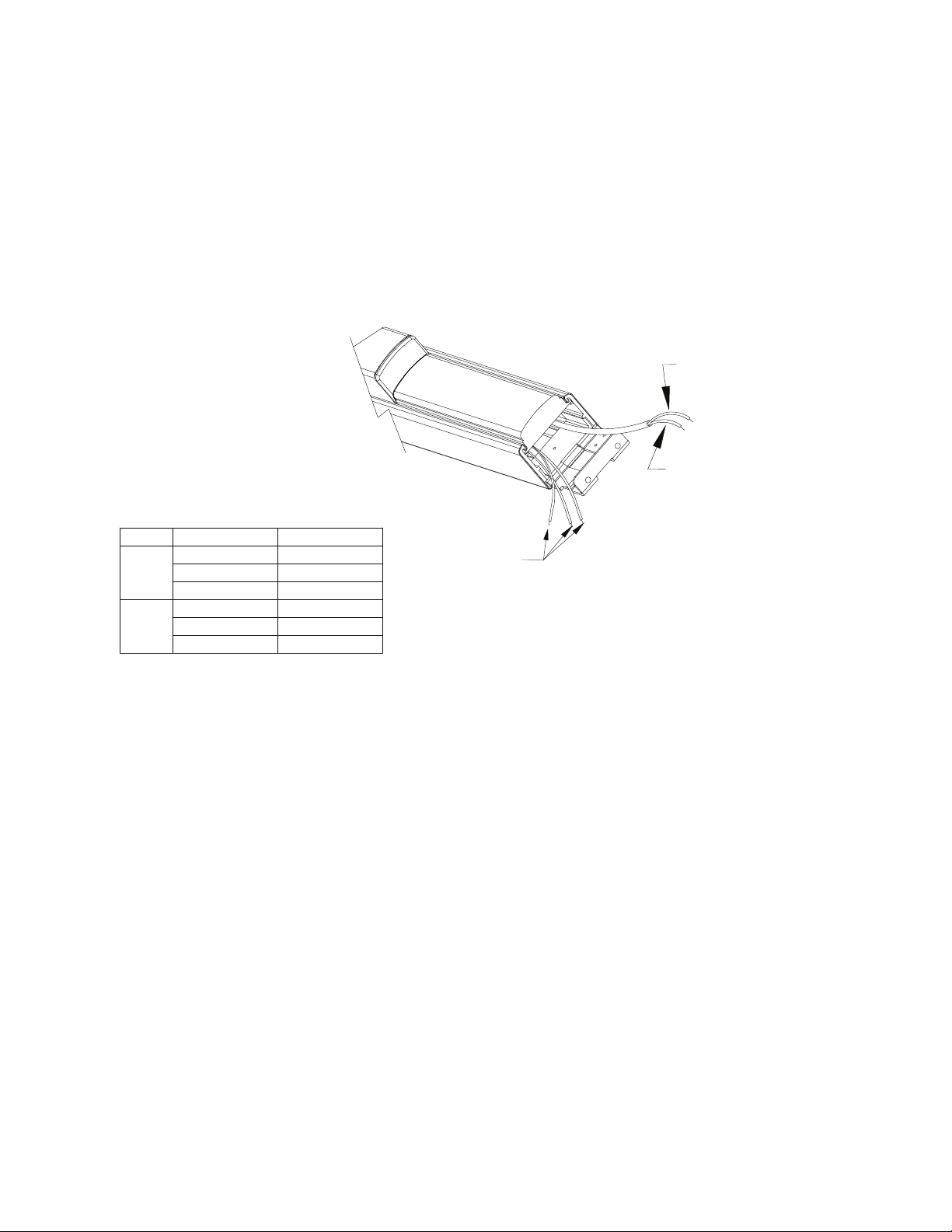
DETEX ER UNITS REQUIRE A DETEX POWER
SUPPLY/CONTROLLER; DETEX P/N 81-800-X, 82-800-X, OR 83-800-X
SEE POWER SUPPLY INSTALLATION INSTRUCTIONS(PACKAGED
WITH POWER SUPPLY) FOR COMPLETE INSTALLATION
WIRES FROM EX OR EXV SWITCH
Amperage Wire Color Switch Position
50mA
max.
3A
max.
Grey
Brown
Yellow
Grey/Red
Brown/Red
Yellow/Red Open
Closed
Common
Open
Closed
Common
ER CONFIGURATION
PROCEDURE.
POWER CABLE FROM ER MODULE
(CONNECT TO POWER SUPPLY)
(Optional)
See
Chart
BLACK(-)
RED (+)
NOTE: POLARITY
SENSITIVE
CONNECTIONS FOR THE ER MODEL
The red and black wires should be connected to the power supply control board (81-800, 82-800, or 83-800,
depending on the door configuration). See power supply instructions 101339 or 101340 as appropriate for typical
connections.
RETRACTING THE LATCH
The ER device must be connected to a Detex power supply/controller, 81-800, 82-800 or 83-800. With all the
conn
ections made according to the power supply instructions, closing the contact will retract the latch. The
pushpad will be pulled down as the latch and deadbolt are retracted. The latch is held by an internal dogging
assembly until the contact is released/opened.
HOLDING THE LATCH RETRACTED
ER model holds the latch retracted as long as the control switch is maintained(closed).
RELEASING THE LATCH
ER is an
electronically dogged latch. Opening the control switch (or contacts) causes the latching mechanism to
release. If an 8X-800 series Detex power supply is used, there is a slight delay from the opening of the switch
contacts to the release of the latch. This delay is intended for external signaling and is described in the power
supply instructions.
103104 Page 8
Page 9
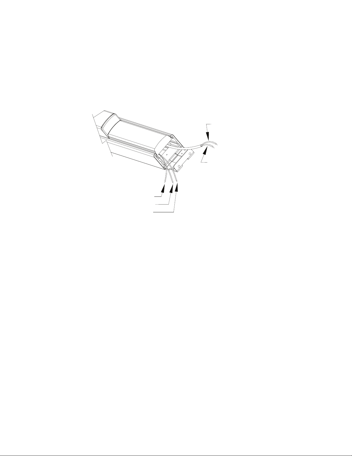
ED CONFIGURATION
DETEX ED UNITS MAY BE OPERATED FROM A 24 V AC OR DC
SOURCE OR WITH A DETEX POWER SUPPLY
(NOTE: FIRE RATED DEVICES MUST USE 80-800-X POWER SUPPLY)
POWER CABLE FROM ED MODULE
(CONNECT TO POWER SUPPLY)
BLACK(-)
RED (+)
WIRES FROM EX SWITCH
(Optional)
GREY (CLOSED)
BROWN (COMMON)
YELLOW (OPEN)
CONNECTIONS FOR THE ED MODEL
For transformer operation, the ED device can use a transformer or power supply. Use Detex part number
PP-5152-2 transformer or approved 24 volt Class 2 equivalent rated at 40 VA or higher. An appropriate switch
must be used to control the power to the device. See Figure 1 on page 10 for a typical installation. Detex power
supply 80-800 may also be used. See
80-800 power supply. This is because transformers cannot be controlled by the building's fire system. Connections
to the building's fire system are described in the power supply instructions.
RETRACTING THE LATCH
The ED model is electrically dogged, but has no mechanism to retract the latch. Once the switch is
activated/clos
reaches the proper amount of travel, it will automatically latch into place. The pushpad will be held in this position
as long as the control switch is maintained(closed).
HOLDING THE LATCH RETRACTED
ED model holds the latch retracted as long as the control switch is maintained(closed).
RELEASING THE LATCH
ED is a
release the lock.
ed and power is supplied to the device, press the pushpad to open the door. As the pushpad
n electronically dogged latch. Opening the control switch (or contacts) causes the latching mechanism to
Figure 2 on page 10 for a typical installation. Fire rated doors must use the
103104 Page 9
Page 10
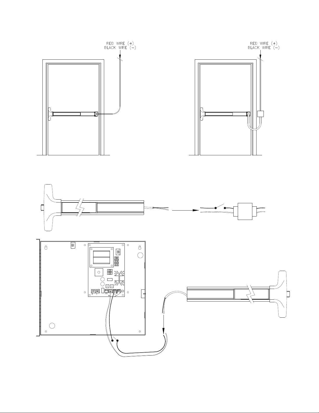
SEE POWER SUPPLY
INSTRUCTIONS FOR
TERMINATION
RISER DIAGRAM
2 Wires
SEE POWER SUPPLY
INSTRUCTIONS FOR
TERMINATION
FOR LONG WIRE RUNS,
SEE RECOMMENDED WIRE
GAUGE IN POWER SUPPLY
INSTRUCTIONS
ELECTRIFIED HINGE INSTALLATION
(MIN 22 GA WIRE)
See 80-800-X instructions
for fire loop connections &
voltage selection
OPTIONAL JB-1 JUNCTION BOX INSTALLATION
WITH 10' FLEX CONDUIT TO DETEX POWER SUPPLY
Typical ED Connection Diagrams
Maintain switch
120VAC 1 Amp
(call Detex for model numbers)
24VAC output
Fig. 1
ED with transformer
24VAC output transformer
Detex p/n PP-5152-2
or approved equivalent
120VAC
input
Fig. 2
ED with power supply
Maintain switch
120VAC 1 Amp
(call Detex for
model numbers)
Black to Negative
103104 Page 10
Red to Positive
Page 11
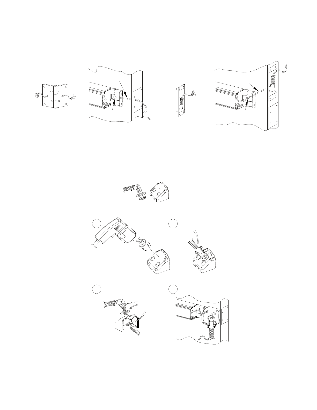
HARDWIRE TRANSFER OPTIONS
(Requirements: Minimum 6 Conductor Wires, Maximum 12 Conductor Wires)
Electric Hinge
p/n: EWH8-X
Note: For high traffic areas an electric through-wire hinge or power transfer is recommended.
Electric Hinge Endcap Prep
Wire chase through door
1/2" Hole through the
inside door face
Value Series Flex Conduit/End Cap Kit
p/n: FCV
Power Transfer
p/n: PT-5
Power Transfer Endcap Prep
Wire chase through door
1/2" Hole through the
inside door face
VALUE SERIES FLEX CONDUIT INSTALLATION
1
2
Drill 7/8" hole
through center guide
3
Fasten until
hand-tight
4
Adjust for handing
(LHR shown)
103104 Page 11
Page 12
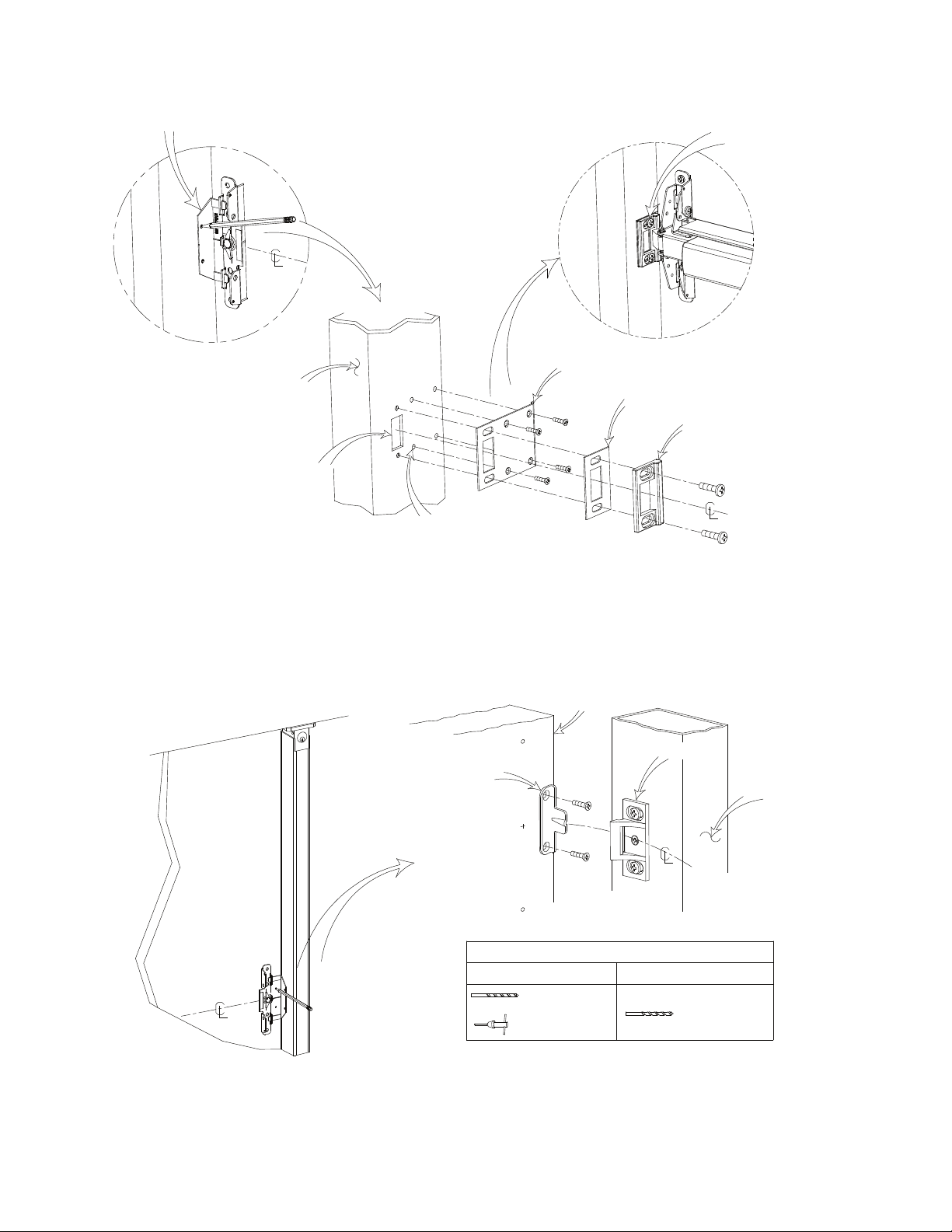
98 Strike locator
Door frame
Cutout per
98 Strike
98 STRIKE INSTALLATION
(when required)
Shield (if necessary)
Mark and drill holes as necessary.
#7 for 1/4-20 machine screws,
For #14 self-drilling screws, no pilot
hole necessary.
7/64" for 6-32 machine screws,
9/64" for #6 sheetemtal screws
(see fastener table)
Align the strike with
the latchbolt.
Firmly tighten screws
Shim (if necessary)
98 Strike
STRIKE HOOK INSTALLATION
(Caution: This installation is required on fire rated door openings with removable mullion.)
Door
Door
Door
Strike hook
For mounting hole locations use Strike Locator (Template) provided.
DRILL CHART
10-24 Machine screw
#25 or 9/64"
tap 10-24
99 strike
Mullion post
#10 Sheetmetal screw
#22 or 5/32"
pilot hole
103104 Page 12
Page 13
Glass Bead Kit
Catalog No: GB2 - Glass Bead Kit, 40 series
p/n: 101644
Sex Nut
Optional Accessories
#1/4-20 X 1-1/2" Screw
(4) Included
The #10-32 kit is available in (4) finishes:
Catalog No: SN2 Brushed Brass BHMA 606 Finish
Catalog No: SN2 Oil Rubbed Bronze BHMA 613 Finish
Catalog No: SN2 Brushed Chrome BHMA 626 Finish
Catalog No: SN2 Stainless Steel BHMA 630 Finish
p/n: 101617-X
Tamper Kit
(Security Kit)
Catalog No: SSK3
p/n: 101233
Security Screws
Security Pin TORX Bits provided
Double Door Strike Kit
Catalog No: 94
p/n: 102212-1
Power Supply
DETEX
The #1/4-20 kit is available in (4) finishes:
Catalog No: SN1 Brushed Brass BHMA 606 Finish
Catalog No: SN1 Oil Rubbed Bronze BHMA 613 Finish
Catalog No: SN1 Brushed Chrome BHMA 626 Finish
Catalog No: SN1 Stainless Steel BHMA 630 Finish
p/n: 101616-X
R
Power Supply Product
80-800-X
81-800-X
82-800-X ER Dual Door
83-800-X ER Dual Door w/ Independent Operator
ED Single Door
ER SIngle Door
The following Models in the series were evaluated by UL: Controlled Exit Panic Devices; Model V40. These devices may
be suffixed with 01, 02, 03, 08, 09, or 14 followed by A, AN, BN, CN, DN, DNT, DNU, MN, P, PN, or WS followed by BP2
or BP8 followed by 605, 606, 611, 612, 613, 625, 626, 628, 629, 630, or 711 followed by the RHR or LHR, followed by ED
or ER, which may be followed by LD or CD, followed
by 628 or 711, followed by 98 or 99, followed by 36 or 48.
103104 Page 13
 Loading...